EP3422689A1 - Image reading apparatus, binding member detecting apparatus, and image reading system - Google Patents
Image reading apparatus, binding member detecting apparatus, and image reading system Download PDFInfo
- Publication number
- EP3422689A1 EP3422689A1 EP18180193.7A EP18180193A EP3422689A1 EP 3422689 A1 EP3422689 A1 EP 3422689A1 EP 18180193 A EP18180193 A EP 18180193A EP 3422689 A1 EP3422689 A1 EP 3422689A1
- Authority
- EP
- European Patent Office
- Prior art keywords
- document
- binding member
- detector
- image reading
- unit
- Prior art date
- Legal status (The legal status is an assumption and is not a legal conclusion. Google has not performed a legal analysis and makes no representation as to the accuracy of the status listed.)
- Granted
Links
Images







Classifications
-
- H—ELECTRICITY
- H04—ELECTRIC COMMUNICATION TECHNIQUE
- H04N—PICTORIAL COMMUNICATION, e.g. TELEVISION
- H04N1/00—Scanning, transmission or reproduction of documents or the like, e.g. facsimile transmission; Details thereof
- H04N1/00002—Diagnosis, testing or measuring; Detecting, analysing or monitoring not otherwise provided for
- H04N1/00007—Diagnosis, testing or measuring; Detecting, analysing or monitoring not otherwise provided for relating to particular apparatus or devices
- H04N1/00013—Reading apparatus
-
- B—PERFORMING OPERATIONS; TRANSPORTING
- B65—CONVEYING; PACKING; STORING; HANDLING THIN OR FILAMENTARY MATERIAL
- B65H—HANDLING THIN OR FILAMENTARY MATERIAL, e.g. SHEETS, WEBS, CABLES
- B65H31/00—Pile receivers
- B65H31/34—Apparatus for squaring-up piled articles
- B65H31/36—Auxiliary devices for contacting each article with a front stop as it is piled
-
- B—PERFORMING OPERATIONS; TRANSPORTING
- B65—CONVEYING; PACKING; STORING; HANDLING THIN OR FILAMENTARY MATERIAL
- B65H—HANDLING THIN OR FILAMENTARY MATERIAL, e.g. SHEETS, WEBS, CABLES
- B65H31/00—Pile receivers
- B65H31/30—Arrangements for removing completed piles
- B65H31/3027—Arrangements for removing completed piles by the nip between moving belts or rollers
-
- G—PHYSICS
- G03—PHOTOGRAPHY; CINEMATOGRAPHY; ANALOGOUS TECHNIQUES USING WAVES OTHER THAN OPTICAL WAVES; ELECTROGRAPHY; HOLOGRAPHY
- G03G—ELECTROGRAPHY; ELECTROPHOTOGRAPHY; MAGNETOGRAPHY
- G03G15/00—Apparatus for electrographic processes using a charge pattern
- G03G15/65—Apparatus which relate to the handling of copy material
- G03G15/6538—Devices for collating sheet copy material, e.g. sorters, control, copies in staples form
- G03G15/6541—Binding sets of sheets, e.g. by stapling, glueing
-
- H—ELECTRICITY
- H04—ELECTRIC COMMUNICATION TECHNIQUE
- H04N—PICTORIAL COMMUNICATION, e.g. TELEVISION
- H04N1/00—Scanning, transmission or reproduction of documents or the like, e.g. facsimile transmission; Details thereof
- H04N1/00127—Connection or combination of a still picture apparatus with another apparatus, e.g. for storage, processing or transmission of still picture signals or of information associated with a still picture
- H04N1/00204—Connection or combination of a still picture apparatus with another apparatus, e.g. for storage, processing or transmission of still picture signals or of information associated with a still picture with a digital computer or a digital computer system, e.g. an internet server
- H04N1/00236—Connection or combination of a still picture apparatus with another apparatus, e.g. for storage, processing or transmission of still picture signals or of information associated with a still picture with a digital computer or a digital computer system, e.g. an internet server using an image reading or reproducing device, e.g. a facsimile reader or printer, as a local input to or local output from a computer
-
- H—ELECTRICITY
- H04—ELECTRIC COMMUNICATION TECHNIQUE
- H04N—PICTORIAL COMMUNICATION, e.g. TELEVISION
- H04N1/00—Scanning, transmission or reproduction of documents or the like, e.g. facsimile transmission; Details thereof
- H04N1/00567—Handling of original or reproduction media, e.g. cutting, separating, stacking
- H04N1/00639—Binding, stapling, folding or perforating, e.g. punching
-
- H—ELECTRICITY
- H04—ELECTRIC COMMUNICATION TECHNIQUE
- H04N—PICTORIAL COMMUNICATION, e.g. TELEVISION
- H04N1/00—Scanning, transmission or reproduction of documents or the like, e.g. facsimile transmission; Details thereof
- H04N1/00567—Handling of original or reproduction media, e.g. cutting, separating, stacking
- H04N1/00663—Indicating relating to handling of media
-
- H—ELECTRICITY
- H04—ELECTRIC COMMUNICATION TECHNIQUE
- H04N—PICTORIAL COMMUNICATION, e.g. TELEVISION
- H04N1/00—Scanning, transmission or reproduction of documents or the like, e.g. facsimile transmission; Details thereof
- H04N1/00681—Detecting the presence, position or size of a sheet or correcting its position before scanning
- H04N1/00742—Detection methods
- H04N1/00748—Detecting edges, e.g. of a stationary sheet
-
- H—ELECTRICITY
- H04—ELECTRIC COMMUNICATION TECHNIQUE
- H04N—PICTORIAL COMMUNICATION, e.g. TELEVISION
- H04N1/00—Scanning, transmission or reproduction of documents or the like, e.g. facsimile transmission; Details thereof
- H04N1/00795—Reading arrangements
-
- H—ELECTRICITY
- H04—ELECTRIC COMMUNICATION TECHNIQUE
- H04N—PICTORIAL COMMUNICATION, e.g. TELEVISION
- H04N1/00—Scanning, transmission or reproduction of documents or the like, e.g. facsimile transmission; Details thereof
- H04N1/32—Circuits or arrangements for control or supervision between transmitter and receiver or between image input and image output device, e.g. between a still-image camera and its memory or between a still-image camera and a printer device
- H04N1/32609—Fault detection or counter-measures, e.g. original mis-positioned, shortage of paper
- H04N1/32625—Fault detection
- H04N1/3263—Fault detection of reading apparatus or transmitter, e.g. original jam
-
- H—ELECTRICITY
- H04—ELECTRIC COMMUNICATION TECHNIQUE
- H04N—PICTORIAL COMMUNICATION, e.g. TELEVISION
- H04N1/00—Scanning, transmission or reproduction of documents or the like, e.g. facsimile transmission; Details thereof
- H04N1/32—Circuits or arrangements for control or supervision between transmitter and receiver or between image input and image output device, e.g. between a still-image camera and its memory or between a still-image camera and a printer device
- H04N1/32609—Fault detection or counter-measures, e.g. original mis-positioned, shortage of paper
- H04N1/32646—Counter-measures
- H04N1/32651—Indicating or reporting
- H04N1/32657—Indicating or reporting locally
-
- B—PERFORMING OPERATIONS; TRANSPORTING
- B65—CONVEYING; PACKING; STORING; HANDLING THIN OR FILAMENTARY MATERIAL
- B65H—HANDLING THIN OR FILAMENTARY MATERIAL, e.g. SHEETS, WEBS, CABLES
- B65H2801/00—Application field
- B65H2801/03—Image reproduction devices
- B65H2801/06—Office-type machines, e.g. photocopiers
Definitions
- the present invention relates to an image reading apparatus which reads a document.
- the invention further relates to a binding member detecting apparatus which detects a binding member binding the document and an image reading system which includes the binding member detecting apparatus.
- JP-A-9-077282 discloses a document feeding apparatus including a non-contact metal detector for detecting a binding needle (such as a staple) in an upstream portion in a document transport direction rather than a transport roller for separating the documents one by one and transporting the documents.
- a binding needle such as a staple
- the metal detector is provided in each of a cover to which the transport roller is attached and a cursor for aligning the document in a width direction orthogonal to a moving direction of the document.
- the metal detector detects the binding needle after rotation of the transport roller, that is, a document feeding operation is started, the document feeding apparatus stops to drive the transport roller or the like.
- An advantage of some aspects of the invention is to reliably prevent a document from being damaged when a feeding operation is performed on a document bundle bound by a binding member.
- an image reading apparatus including: a reading unit that reads a document; a document setting unit that sets the document to be fed toward the reading unit; and a binding member detector that detects a binding member binding the document and is provided in an outside of an installation region of the document setting unit.
- the image reading apparatus includes the reading unit that reads the document, the document setting unit that sets the document to be fed toward the reading unit, and the binding member detector that detects the binding member binding the document and is provided in an outside of an installation region of the document setting unit. That is, since the binding member detector is provided at a position at which the document is detected before the document is set to the document setting unit and the binding member is detected before the document feeding operation from the document setting unit is started, it is possible to more reliably prevent the document from being damaged.
- the binding member detector be provided on a side surface of a housing constituting an outside of the image reading apparatus.
- the binding member detector is provided on the side surface of the housing constituting the outside of the image reading apparatus, it is possible to more reliably prevent the document from being damaged.
- the image reading apparatus further include: a document receiving unit that receives the document read and discharged, and in which the binding member detector is provided on a lower side of the document receiving unit.
- the binding member detector is provided on the lower side of the document receiving unit, it is possible to more reliably prevent the document from being damaged.
- the binding member detector include a first portion and a second portion disposed to face the first portion and detect the binding member by passing the document through between the first portion and the second portion.
- the binding member detector includes the first portion and the second portion disposed to face the first portion and is configured to detect the binding member by passing the document through between the first portion and the second portion, it is possible to prevent the document from largely deviating from a detectable region of the binding member and to more reliably detect the binding member.
- an interval between the first portion and the second portion correspond to a maximum loading height of the document settable to the document setting unit.
- the interval between the first portion and the second portion corresponds to the maximum loading height of the document settable to the document setting unit, it is possible to perform both of the detecting operation of the binding member by using the binding member detector and the operation of determining whether or not the document can be loaded in the document setting unit and to improve availability of a user.
- an interval between the first portion and the second portion be configured to be adjustable.
- the binding member detector since the binding member detector includes the adjustable interval between the first portion and the second portion, by adjusting the interval, it is possible to adjust an output (for example, magnetic field formed by oscillation coil) so as to detect the binding member. As a result, for example, by decreasing the interval, it is possible to weaken the magnetic field and to suppress that the magnetic field has a bad influence on the image reading apparatus or the periphery of the image reading apparatus.
- an output for example, magnetic field formed by oscillation coil
- an image reading apparatus including: a reading unit that reads a document; a document setting unit that sets the document to be fed toward the reading unit; and a binding member detector that detects a binding member binding the document, in which the binding member detector is provided to be movable along a document feeding direction from and to the document setting unit.
- the image reading apparatus includes the reading unit that reads the document, the document setting unit that sets the document to be fed toward the reading unit, and the binding member detector that detects the binding member binding the document. Since the binding member detector is provided to be movable along the document feeding direction from and to the document setting unit, it is possible to detect the binding member before the feeding operation is started by moving the binding member detector along the document feeding direction. As a result, it is possible to more reliably prevent the document from being damaged.
- the image reading apparatus further include: a notification unit that performs notification of detection of the binding member by the binding member detector.
- the image reading apparatus since the image reading apparatus includes the notification unit that performs notification of the detection of the binding member by the binding member detector, it is possible to promptly and reliably notify the user of the presence of the binding member and to improve the availability of the user.
- the image reading apparatus further include: a feeding unit that transports the document from the document setting unit; and a document detector that detects passage of the document when the document passes through the binding member detector, in which a controller that controls the feeding unit causes the feeding unit to perform a document feeding operation after the document detector detects the passage of the document.
- the controller that controls the feeding unit causes the feeding unit to perform the document feeding operation after the document detector detects the passage of the document, the detecting operation using the binding member detector is obligatorily performed before the document is fed by the feeding unit and it is possible to more reliably prevent the document P being damaged.
- document passes through binding member detector does not mean only a form in which the document passes through the binding member detector fixedly provided, but also a form in which the document passes through the binding member detector by moving the binding member detector from and to the document.
- the binding member detector detect a change in a magnetic field to detect the binding member
- the apparatus further includes: a document detector that detects passage of the document through the binding member detector; and a controller that receives information on the document detected by the document detector and information on the change in the magnetic field detected by the binding member detector, and in which in a case where the binding member detector detects the change in the magnetic field in a document undetected state in which the document detector does not detect the passage of the document, the controller executes a predetermined process.
- the controller 40 performs the predetermined process, so that it is possible to more accurately detect the binding member.
- Predetermined process is not limited to control of components of the image reading apparatus by the controller, but also includes a process such as calculation inside the controller, that is, an invisible process other than a process of which a processing result is visible from an outside.
- the binding member detector be detachably provided with respect to a main body of the image reading apparatus.
- the main body of the image reading apparatus is provided with the detachable binding member detector, by removing out the binding member detector from the main body, depending on a form of the document, the operation of detecting the binding member by the binding member detector becomes easier.
- a binding member detecting apparatus that detects a binding member binding a document, the apparatus including: a first portion and a second portion disposed to face the first portion, and in which the binding member is detected by passing the document through between the first portion and the second portion.
- the binding member detecting apparatus since the binding member detecting apparatus includes the first portion and the second portion disposed to face the first portion and is configured to detect the binding member by passing the document through between the first portion and the second portion, it is possible to prevent the document from largely deviating from a detectable region of the binding member and to more reliably detect the binding member.
- the first portion and the second portion be provided with an interval in a horizontal direction and a contact portion that comes into contact with an end of the document be provided on a lower side between the first portion and the second portion.
- first portion and the second portion are provided with the interval in the horizontal direction and the contact portion that comes into contact with an end of the document is provided on the lower side between the first portion and the second portion, it is possible to simultaneously align the end of the document and detect the binding member and it is possible to improve the availability of the user.
- an image reading system including: an image reading apparatus that includes a reading unit which reads a document and a document setting unit which sets the document to be fed toward the reading unit; and the binding member detecting apparatus according to the aspect.
- the binding member detecting apparatus obtain a power from the image reading apparatus.
- the binding member detecting apparatus obtains the power from the image reading apparatus, it is unnecessary to prepare the power supply dedicated to the binding member detecting apparatus and it is possible to improve the availability of the user.
- an interval between the first portion and the second portion correspond to a maximum loading height of the document settable to the document setting unit.
- the interval between the first portion and the second portion corresponds to the maximum loading height of the document settable to the document setting unit, it is possible to perform both of the detecting operation of the binding member by using the binding member detecting apparatus and the operation of determining whether or not the document can be loaded in the document setting unit and to improve the availability of the user.
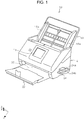
- Fig. 1 is an external perspective view of a scanner according to the invention
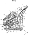
- Fig. 2 is a side sectional view illustrating a document transport path of the scanner according to the invention
- Fig. 3 is a block diagram of the scanner according to the invention
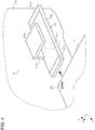
- Fig. 4 is a perspective view illustrating a binding member detector
- Fig. 5 is a side view illustrating a state in which the binding member detector does not detect a binding member and a state in which the binding member detector detects the binding member.
- Fig. 6 is a schematic diagram illustrating a flow of a line of magnetic force in the binding member detector
- Fig. 7 is a side view illustrating a state in which an interval between a first portion and a second portion in the binding member detector is adjusted
- Fig. 8 is a perspective view illustrating a modification example of a binding member detector according to a first embodiment
- Fig. 9 is an external perspective view of an image reading system according to a second embodiment
- Fig. 10 is an external perspective view of a binding member detecting apparatus according to the second embodiment.
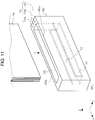
- Fig. 11 is an external perspective view of a modification example of a scanner according to the second embodiment
- Fig. 12 is an external perspective view of a scanner according to a third embodiment
- Fig. 13 is a perspective view illustrating a state in which a document is set to the scanner according to the third embodiment
- Fig. 14 a perspective view illustrating a state in which a binding member detector is moved in a feeding direction of the document in the scanner according to the third embodiment
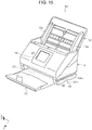
- Fig. 15 is a diagram illustrating another modification example of the binding member detector according to the first embodiment.
- Fig. 16 is a flowchart illustrating a flow of control performed by a controller
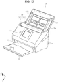
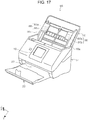
- Fig. 17 is an external perspective view of a scanner according to another embodiment
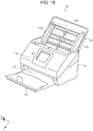
- Fig. 18 is an external perspective view of a scanner according to still another embodiment
- Fig. 19 is a flowchart illustrating a flow of control performed by a controller according to still another embodiment.
- the X direction is an apparatus width direction and a medium width direction
- the Y direction is a medium transport direction in an image reading apparatus
- the Z direction is a direction orthogonal to the Y direction and a direction roughly orthogonal to a surface of the medium transported.
- the +Y direction side is defined as a front surface side of the apparatus and the -Y direction side is defined as a rear surface side of the apparatus.
- a scanner 10 will be described as an example of the image reading apparatus.
- the scanner 10 includes a main body portion 12 (see Fig. 2 ) and a housing 14 which covers the main body portion 12 and constitutes an external surface of the scanner 10.
- a document setting unit 16 which sets the document is provided at an end of the main body portion 12 on a rear surface side of the apparatus.
- the document setting unit 16 is configured to be able to support the document in an inclined posture.
- a plurality of sheets of documents can be set in the document setting unit 16.
- the document setting unit 16 is provided with a pair of edge guides 16a which can be moved in directions to approach each other or in directions to depart from each other and is configured to guide a side portion of the document mounted in the document setting unit 16.
- a user interface unit 18 is provided on a front surface side of the housing 14 of the scanner 10 as "notification unit".
- the user interface unit 18 is configured to include a touch panel and functions as a display unit and an operating unit. By operating the user interface unit 18, it is possible to execute a reading operation of the medium of the scanner 10.
- a discharge unit 20 is provided below the user interface unit 18 on a front surface side of the scanner 10.
- a document receiving unit 22 is provided below the discharge unit 20.
- the document receiving unit 22 is configured to switch between a state in which the document receiving unit 22 is in a lower part of the main body portion 12 and is stored inside the main body portion 12 (see Fig. 2 ) and a state in which the document receiving unit 22 is pulled out from the main body portion 12 to a front surface side (see Fig. 1 ).
- a binding member detector 24 described below is provided on a side surface of the housing 14 which is an outside of an installation region of the document setting unit 16.
- a document transport path 26 in the scanner 10 will be described.
- a bold solid line denoted by reference symbol P indicates a guide path of the document transported along the document transport path 26 in the scanner 10.
- the main body portion 12 is provided with a document setting detection sensor 27 which detects setting of the document to the document setting unit 16, a feeding roller 28 as “feeding unit”, a separating roller 30, a pair of transport rollers 32, an image reading unit 34 as “reading unit”, and a pair of discharge rollers 36 from an upstream side (-Y direction side) to a downstream side (+Y direction side) in the transport direction of the document on a path of the document transport path 26 in the main body portion 12.
- the feeding roller 28 is driven to rotate by a driving source (not illustrated) provided in the main body portion 12 as an example.
- the separating roller 30 is provided to face the feeding roller 28.
- the separating roller 30 is provided in a state of being urged against the feeding roller 28 by an urging unit (not illustrated).
- the separating roller 30 is configured to separate the plurality of sheets of documents so as to transport only the lowest document to be fed to the downstream side in the transport direction when the plurality of sheets of documents is inserted between the feeding roller 28 and the separating roller 30.
- the document supported by the document setting unit 16 in an inclined posture is nipped between the feeding roller 28 and the separating roller 30 and is transported to the pair of transport rollers 32 disposed on the downstream side in the transport direction. Next, the pair of transport rollers 32 transports the document sent from the feeding roller 28 toward the image reading unit 34.
- the image reading unit 34 includes a first reading unit 38A provided to face a lower surface of the document transported along the document transport path 26, that is, a first surface and a second reading unit 38B provided to face an upper surface of the document transported along the document transport path 26, that is, a second surface.
- the first reading unit 38A and the second reading unit 38B are configured as reading units and are configured as CISMs (contact type image sensor modules) as an example.
- the image reading unit 34 reads an image in at least one of the first surface and the second surface of a document P sent to the image reading unit 34 by the pair of transport rollers 32, and then the document P is nipped by the pair of discharge rollers 36 positioned on the downstream side of the image reading unit 34 in the transport direction and is discharged from the discharge unit 20 to the document receiving unit 22.
- a controller 40 will be described with reference to Figs. 2 and 3 .
- the controller 40 is provided in the main body portion 12 illustrated Fig. 2 .
- the controller 40 is configured to include a plurality of electronic components as electric circuits. As illustrated in Fig. 3 , the controller 40 controls reading operations of the first reading unit 38A and the second reading unit 38B, rotation driving of the feeding roller 28, the pair of transport rollers 32, and the pair of discharge rollers 36, and the binding member detector 24 described below.
- controller 40 is configured to control transport of the document P, image reading operation, and binding member detecting operation in the scanner 10 as an example.
- controller 40 may control operation required for executing document reading operation in the scanner 10 according to an instruction from the outside (such as a PC).
- the binding member detector 24 includes a first portion 24a and a second portion 24b.
- the first portion 24a and the second portion 24b face each other and are disposed to be spaced apart in an apparatus height direction of the scanner 10.
- a cavity 42 for passing the document is formed between the first portion 24a and the second portion 24b.
- the binding member detector 24 detects a binding member 44 (see Fig. 5 ) which binds the document bundle.
- the binding member 44 is a binding needle for a stapler (such as a staple) and is formed from a metal member (for example, magnetic substance such as iron or the like).
- a distance of the cavity 42 between the first portion 24a and the second portion 24b is set to a distance L1 (see Fig. 5 ).
- the distance L1 corresponds to a maximum loading height of the document settable in the document setting unit 16.
- a fact that the distance L1 corresponds to the maximum loading height of the document settable in the document setting unit 16 is not limited to a fact that the distance L1 is exactly the same as the maximum loading height of the document settable in the document setting unit 16 and also means a fact that the distance L1 and the maximum loading height include some errors or variation.
- a guide surface 24d which guides a document bundle toward the cavity 42 is formed at each of both ends of an upper surface 24c of the second portion 24b in front/rear directions of the apparatus.
- a magnetic field generator 46 is provided in the first portion 24a.
- the magnetic field generator 46 includes an oscillation coil 46a and an oscillation circuit 46b.
- the oscillation circuit 46b is electrically connected to the controller 40 and is controlled by the controller 40.
- the oscillation coil 46a generates a magnetic field toward a magnetic field detector 48 provided on a side of the second portion 24b.
- the magnetic field generated by the oscillation coil 46a is controlled by the controller 40 via the oscillation circuit 46b and the oscillation frequency and oscillation strength can be changed.
- the magnetic field detector 48 includes a detecting coil 48a and a galvanoscope 48b connected to both ends of the detecting coil 48a.
- the galvanoscope 48b is electrically connected to the controller 40.
- the galvanoscope 48b is configured to transmit a detecting signal to the controller 40 when detecting a change in a magnetic field B.
- the present embodiment may include the galvanoscope, but the present embodiment may include a voltage detector.
- the magnetic field B (a plurality of arrows extended in a lower side direction in Fig. 5 ) generated from the oscillation coil 46a of the magnetic field generator 46 penetrates in a direction orthogonal to the detecting coil 48a. Since a magnetic flux ⁇ obtained by magnetic field B passing through the detecting coil 48a is changed, an electromagnetic induction phenomenon occurs and induced electromotive force is generated at both ends of the detecting coil 48a. In the present embodiment, a change in an induced current flowing by the induced electromotive force is detected by the galvanoscope 48b. In a case of the voltage detector, the voltage detector detects a change of the induced electromotive force.
- the first portion 24a and the second portion 24b are connected with a connecting portion 24e.
- a frame member 25 which corresponds a cross sectional shape of the binding member detector 24 is provided inside the first portion 24a, the second portion 24b, and the connecting portion 24e.
- the frame member 25 is made of a metallic member through which it is easy to pass a line of magnetic force.
- the frame member 25 includes a first portion 25a, a second portion 25b, and a connecting portion 25c.
- the oscillation coil 46a is disposed on a side of the first portion 25a of the frame member 25 and the detecting coil 48a is disposed on a side of the second portion 25b of the frame member 25.
- the magnetic field B oscillated and formed by the oscillation coil 46a is directed toward the detecting coil 48a.
- the line of magnetic force of the magnetic field B passed through the detecting coil 48a passes through the frame member 25 in order of the second portion 25b, the connecting portion 25c, and the first portion 25a of the frame member 25 and returns to a side of the oscillation coil 46a.
- a bold line in Fig. 6 schematically illustrates a flow of the line of magnetic force in the frame member 25.
- the line of magnetic force passes through the frame member 25 to return from the detecting coil 48a to the oscillation coil 46a, it is possible to simultaneously suppress influence of a disturbance by the binding member detector 24, to reduce a leak of the line of magnetic force from the binding member detector 24 to an outside, and to suppress that the magnetic field has a bad influence on the outside of the binding member detector 24.
- Figs. 4 and 5 an operation of detecting the binding member will be described.
- an end of the document bundle P1 which is a plurality of documents P bound by the binding member 44 passes from a front surface side of the apparatus to a rear surface side of the apparatus via the cavity 42 of the binding member detector 24.
- the binding member 44 in a case where the binding member 44 exists in the end of the document bundle P1, when the document bundle P1 crosses the magnetic field B, the binding member 44 also crosses the magnetic field B.
- the magnetic flux ⁇ of the magnetic field B is changed by the binding member 44, so that the induced current is changed.
- the galvanoscope 48b detects the change in the induced current.
- the end of the document bundle P1 passes through the cavity 42 from the front surface side of the apparatus, but the end of the document bundle P1 may be passed through the cavity 42 from the rear surface side of the apparatus.
- the galvanoscope 48b transmits a detecting signal to the controller 40 when detecting the change in the magnetic field B.
- the controller 40 displays a warning message that the binding member detector 24 detects the binding member 44, that is, an example of notification to the user interface unit 18 as a notification unit.
- the user can avoid that the document bundle P1 bound by the binding member 44 is erroneously set as it is and feeding is started, so the document is torn.
- the binding member detector 24 includes at least a document detector 50.
- the document detector 50 is disposed in each of an upstream side and a downstream side of the magnetic field B in a transport direction of the document bundle P1 between the first portion 24a and the second portion 24b.
- the document detector 50 is configured to include an optical sensor, for example, is configured to include a transmissive sensor.
- the document detector 50 includes a light emitting unit 50a provided at the first portion 24a and a light receiving unit 50b provided at the second portion 24b.
- the document detector 50 is electrically connected with the controller 40 and is configured to transmit the detecting signals to the controller 40.
- the document bundle P1 when the document bundle P1 passes from the front surface side of the apparatus to the rear surface side of the apparatus via the cavity 42, the document bundle P1 crosses an optical axis R (fine line denoted by reference symbol R in Fig. 5 ) between the light emitting unit 50a and the light receiving unit 50b in the document detector 50. Accordingly, the document detector 50 detects that the document bundle P1 is inserted in the cavity 42 and transmits the detecting signal to the controller 40.
- R optical axis
- the controller is set to receive the detecting signal from the document detector 50 in a case where the user inputs an instruction to operate the document feeding operation to the user interface unit 18. Then, the controller 40 is set to start the document feeding operation in a case where the binding member detector 24 does not detect the binding member 44.
- the binding member 44 crosses the magnetic field B and a binding member detecting signal is transmitted to the controller 40. Further, when the document bundle P1 is moved to the downstream side in the document moving direction, the document bundle P1 crosses the optical axis R of the document detector 50 on the downstream side (rear surface side of apparatus) and the document detector 50 on the downstream side detects the document bundle P1.
- a timing when the magnetic field detector 48 detects the binding member 44 and a timing when the document detector 50 on the downstream side detects the document bundle P1 may sometimes be reversed.
- Fig. 5 illustrates a state in which the binding member 44 is on a tip side of the document in the document moving direction.
- the binding member 44 is on a rear end side of the document in the document moving direction, after the document detector 50 on the downstream side detects the document bundle P1, the binding member 44 is detected.
- the controller 40 receives both of the detecting signal from the document detector 50 on the upstream side and the detecting signal from the document detector 50 on the downstream side and determines whether or not the document bundle P1 passes through the binding member detector 24.
- the controller 40 writes information on a time of the detecting operation and a detecting result (whether or not document is normally passed through binding member detector 24 and binding member is detected) in a storage unit (not illustrated).
- the fact that the document is normally passed through the binding member detector 24 means a state in which both of the document detectors 50 on the upstream side and the downstream side detect the document when the document passes through the cavity 42.
- the binding member detector 24 After then, for example, it is determined whether or not the binding member detector 24 performs the detecting operation within a predetermined time period (for example, within one minute) from a case where the instruction to start the feeding operation is input.
- the controller 40 reads the information on the time of the detecting operation and the detecting result (whether or not document is normally passed through binding member detector 24 and binding member is detected) stored in the storage unit (not illustrated).
- the controller 40 displays the warning message (for example, "Perform operation of detecting binding member, please") or the like to the user interface unit 18.
- the binding member detector 24 obligatorily performs the operation of detecting the binding member 44 before the document P is fed from the document setting unit 16, it is possible to prevent the document bundle P1 bound by the binding member 44 from being fed from the document setting unit 16 and to reliably suppress damage to the document.
- the controller 40 displays the warning message (for example, "Binding member is detected. Check, please") or the like to the user interface unit 18.
- the feeding operation is not started, and the controller 40 displays the warning message (for example, "Perform operation of detecting binding member again, please") or the like to the user interface unit 18.
- the flowchart in Fig. 16 illustrates the flow of the control described above.
- the controller 40 determines whether or not the upstream and downstream document detectors 50 included in the binding member detector 24 detect the document within the predetermined time period after the instruction is received (step S102).
- the document is detected (Yes in step S102)
- a reading job that is, the feeding operation is started (step S104).
- the controller 40 displays an alert message to the user interface unit 18 and performs an error end.
- the controller 40 may perform the following processes based on receiving of the detecting signal (of detecting a state in which document is set to the document setting unit 16) from the document setting detection sensor 27 (see Figs. 2 and 3 ). For example, in a case where the controller 40 determines that the document is set to the document setting unit 16 based on the detecting signal from the document setting detection sensor 27, the controller 40 determines whether or not both of the document detector 50 on the upstream side and the document detector 50 on the downstream side have detected the document and the binding member detector 24 has detected the binding member 44 within a predetermined time period immediately before the detecting signal is received.
- the controller 40 displays the warning message (for example, "Perform operation of detecting binding member, please") or the like to the user interface unit 18. Alternately, even if both of the document detector 50 on the upstream side and the document detector 50 on the downstream side do not detect the document, in a case where the binding member 44 is detected, the controller 40 displays the warning message (for example, "Binding member is detected. Check, please”) or the like to the user interface unit 18.
- the controller 40 accepts the following processes, specifically the reading job.
- the controller 40 determines that the document is normally passed through the binding member detector 24. Further, in a case where the magnetic field detector 48 detects the change in the magnetic field B when the document bundle P1 crosses the magnetic field B, information (binding member detecting signal) on detection of the change in the magnetic field B is transmitted to the controller 40. As a result, the controller 40 determines that the binding member 44 is detected in a state in which the document is normally passed through the binding member detector 24.
- the magnetic field detector 48 detects the change in the magnetic field B and the information on the detection of the change in the magnetic field B is transmitted to the controller 40.
- the disturbance factor includes, for example, a case where an electromagnetic wave emitted from an electronic apparatus is detected, a case where an object having a magnetic force approaches the binding member detector 24, and the like.
- the controller 40 in case of receiving the information on the change in the magnetic field B, the controller 40 is configured to execute a predetermined process. Specifically, as an example of the predetermined process, the controller 40 displays the warning message to the user interface unit 18 as the notification unit. By displaying the warning message, it is possible to urge the user to retry the operation of detecting the binding member and to appropriately detect the binding member 44.
- the magnetic field detector 48 detects the change in the magnetic field. Based on the detecting result, the controller 40 can detect the change in the magnetic field in a non-oscillation state of the magnetic field generator 46. In the present embodiment, for example, by comparing information on the detection of the change in the magnetic field B in an oscillation state of the magnetic field generator 46 with information on the detection of a change in time in the non-oscillation state, the controller 40 can increase detection accuracy of the change in the magnetic field B in the oscillation state of the magnetic field generator 46, that is, accuracy of detecting the binding member 44.
- an image reading system 54 includes a scanner 56 and a binding member detecting apparatus 58 which is a separate apparatus from the scanner 56.
- the scanner 56 has the same configuration as the scanner 10 except that the binding member detector 24 is provided on a side surface of the housing 14.
- the scanner 56 and the binding member detecting apparatus 58 are connected with each other via a cable 59.
- the cable 59 includes both a signal line and a power line as an example, but the signal line and the power line may be configured as separate cables.
- the binding member detecting apparatus 58 includes a first portion 58a and a second portion 58b disposed to face the first portion 58a.
- the first portion 58a and the second portion 58b are connected with a connecting portion 58e.
- a cavity 60 for passing the document bundle P1 is provided between the first portion 58a and the second portion 58b facing each other.
- a distance L3 of the cavity 60 between the first portion 58a and the second portion 58b corresponds to the maximum loading height of the document settable in the document setting unit 16.
- the frame member 25 (not illustrated) is provided inside the first portion 58a, the second portion 58b, and the connecting portion 58e of the binding member detecting apparatus 58.
- a guide surface 58d which guides a document bundle toward the cavity 60 is formed at each of both ends of an upper surface 58c of the second portion 58b in front/rear directions of the apparatus.
- the magnetic field generator 46 (not illustrated) is provided in the first portion 58a as an example.
- the magnetic field detector 48 is provided in the second portion 58b.
- a transceiver 62 (two-dot chain line denoted by reference symbol 58 in Fig. 10 ) is provided inside the second portion 58b.
- the transceiver 62 is configured to include a plurality of electronic components as electric circuits.
- the transceiver 62 is configured to transmit the detecting signal of the binding member 44 by the binding member detecting apparatus 58 to the controller 40 (see Fig. 2 ) of the scanner 56.
- a notification unit 64 is provided in the first portion 58a.
- the notification unit 64 includes a plurality of indicator lamps 64A, 64B, and 64C.
- the indicator lamp 64A functions as a lamp indicating whether the binding member detecting apparatus 58 is on or off.
- the binding member detecting apparatus 58 is provided with the document detector 50 (not illustrated) on each of the upstream side and the downstream side of the magnetic field generator 46 and the magnetic field detector 48 along the document moving direction.
- the indicator lamp 64B is lit in blue or green. Therefore, the user can visually check that the binding member 44 is not detected.
- the indicator lamp 64C is lit in red or yellow as warning color. Therefore, the user can visually check that the binding member 44 is detected.
- the controller is set to receive the detecting signal from the document detector 50 in a case where the user inputs the instruction to operate the document feeding operation to the user interface unit 18. Then, the controller 40 is set to start the document feeding operation in a case where the binding member detecting apparatus 58 does not detect the binding member 44.
- the controller 40 determines that the document bundle P1 is normally passed through the binding member detecting apparatus 58 and writes information on a time of the detecting operation by the binding member detecting apparatus 58 and a detecting result (whether or not document is normally passed through binding member detecting apparatus 58 and binding member is detected) in the storage unit (not illustrated).
- the binding member detecting apparatus 58 After then, for example, it is determined whether or not the binding member detecting apparatus 58 performs the detecting operation within a predetermined time period (for example, within one minute) from a case where the instruction to start the feeding operation is input.
- the controller 40 reads the information on the time of the detecting operation and the detecting result (whether or not document is normally passed through binding member detecting apparatus 58 and binding member is detected) stored in the storage unit (not illustrated).
- the controller 40 displays the warning message (for example, "Perform operation of detecting binding member, please") or the like to the user interface unit 18.
- the binding member detecting apparatus 58 obligatorily performs the operation of detecting the binding member 44 before the document P is fed from the document setting unit 16, it is possible to prevent the document bundle P1 bound by the binding member 44 as it is being fed from the document setting unit 16 and to reliably suppress damage to the document.
- the controller 40 displays the warning message (for example, "Binding member is detected. Check, please") or the like to the user interface unit 18.
- the feeding operation is not started, and the controller 40 displays the warning message (for example, "Perform operation of detecting binding member again, please") or the like to the user interface unit 18.
- a notification unit 74 is provided on an upper surface of the binding member detecting apparatus 66.
- the notification unit 74 includes a plurality of indicator lamps 74A, 74B, and 74C.
- the indicator lamps 74A, 74B, and 74C have the same configuration as the configuration of the indicator lamps 64A, 64B, and 64C, so that the description will be omitted.
- the binding member detecting apparatus 66 since the document bundle P4 is inserted from an upper side in the apparatus height direction to the cavity 68 and an end portion of the document bundle P4 comes into contact with the contact portion 66c, it is possible to align the document bundle P4. In addition, while preparing the document bundle P4, the binding member detecting apparatus 66 can detect whether or not the binding member 44 exists at the lower end portion of the document bundle P4. As a result, since it is possible to simultaneously perform the operation of preparing the document and the operation of detecting the binding member 44, it is possible to improve workability.
- the binding member detecting apparatus 66 may be automatically moved up and down to scan an entire region in the height direction of the document bundle P4 by using a power of a motor or the like.
- the magnetic field generator 70 and the magnetic field detector 72 are extended over the entire region in the width direction, but instead of this configuration, for example, the magnetic field generator 70 and the magnetic field detector 72 may be configured to have a short length in the width direction of the document and may be movable along the document width direction by a moving unit. Further, the magnetic field generator 70 and the magnetic field detector 72 are moved in the width direction of the document to scan the document bundle, so that it is possible to detect the binding member 44 in the lower end portion of the document bundle P4.
- lengths of the second portions 24b and 58b in a passing direction of the document are longer than lengths of the first portions 24a and 58a, but the embodiment is not limited thereto.
- the lengths of the second portions 24b and 58b in a passing direction of the document may be set to be equal to the lengths of the first portions 24a and 58a.
- a scanner 76 includes a binding member detector 78.
- the binding member detector 78 includes a first portion 78a and a second portion 78b.
- the document setting unit 16 is configured to function as the first portion 78a as an example.
- the first portion 78a is provided inside the document setting unit 16.
- a magnetic field generator (not illustrated) is provided in the first portion 78a.
- the second portion 78b is disposed on a front surface side of the main body portion 12 and to face the document setting unit 16. More specifically, as illustrated in Fig. 13 , in a state in which a document P5 is set to the document setting unit 16, the second portion 78b is disposed to face an end tip in a feeding direction of the document P5. In the present embodiment, the second portion 78b is configured to have a predetermined interval from the document setting unit 16 in an opened state and to be changeable along the document feeding direction.
- a pair of arm portions 80 are provided with an interval in the X axis direction in a lower part of the second portion 78b.
- the arm portion 80 is configured to be able to be switched between a state ( Figs. 12 and 13 ) in which the arm portion 80 is stored in the main body portion 12 and a state ( Fig. 14 ) in which the arm portion 80 is pulled out from the main body portion 12 by a driving source (not illustrated).
- a driving source not illustrated.
- the document setting detection sensor 27 detects the document.
- the controller 40 switches from the state in which the arm portion 80 is stored to the state in which the arm portion 80 is pulled out and causes the second portion 78b to scan the document set to the document setting unit 16.
- the second portion 78b is moved in the document feeding direction and detects the binding member 44 only by setting the document to the document setting unit 16, it is possible to improve workability of the scanner 76.
- the flowchart in Fig. 19 illustrates the flow of the control described above.
- the controller 40 determines whether or not the document exists on the document setting unit 16 based on the detecting signal from the document setting detection sensor 27 (step S201).
- the operation of checking whether the binding member exists that is, the operation of displacing the second portion 78b (step S202) is carried out.
- the controller 40 displays the alert message to the user interface unit 18 and performs the error end.
- step S204 the controller 40 starts the reading job, that is, the feeding operation (step S205).
- the second portion 78b is automatically displaced in the document feeding direction.
- the arm portion 80 may be manually or automatically pulled out or stored, so that the second portion 78b may be displaced. Without the arm portion 80, the user holds the second portion 78b over the document P5, and then the operation of detecting the binding member 44 may be performed.
- the scanner 10 includes the image reading unit 34 which reads the document P, the document setting unit 16 to which the document P to be fed toward the image reading unit 34 is set, and the binding member detectors 24, 52, 78, and 84 which detect the binding member 44 binding the document P and provided outside the installation region of the document setting unit 16. According to this configuration, by detecting the binding member 44 before the feeding operation of the document P from the document setting unit 16 is started, it is possible to more reliably prevent the document P from being damaged.
- the binding member detectors 24 and 84 are provided on the side surface of the housing 14 constituting an outside surface of the scanner 10.
- the document receiving unit 22 which receives the document P discharged after the document P is read.
- the binding member detector 52 is provided on a lower side of the document receiving unit 22.
- the binding member detectors 24, 52, 78, and 84 includes the first portions 24a, 78a, and 84a and the second portions 24b, 78b, and 84b disposed to face the first portions 24a, 78a, and 84a.
- the binding member detectors 24, 52, 78, and 84 detect the binding member 44. According to this configuration, it is possible to prevent the document from largely deviating from a detectable region of the binding member 44 and to more reliably detect the binding member 44.
- the intervals between the first portions 24a, 78a, and 84a and the second portions 24b, 78b, and 84b correspond to the maximum loading height of the document settable in the document setting unit 16. According to this configuration, since the intervals between the first portions 24a, 78a, and 84a and the second portions 24b, 78b, and 84b correspond to the maximum loading height of the document settable in the document setting unit 16, it is possible to perform both of the detecting operation of the binding member 44 by using the binding member detectors 24, 52, 78, and 84 and the operation of determining whether or not the document can be loaded in the document setting unit 16 and to improve availability of the user.
- the interval (cavity 42) between the first portion 24a and the second portion 24b is configured to be adjustable. According to this configuration, by adjusting the interval (cavity 42), it is possible to adjust an output (for example, magnetic field B formed by oscillation coil 46a) so as to detect the binding member 44. As a result, for example, by decrease of the interval (cavity 42), it is possible to weaken the magnetic field and to suppress that the magnetic field has a bad influence on the scanner 10 or the periphery of the scanner 10.
- the scanner 76 includes the image reading unit 34 which reads the document P, the document setting unit 16 to which the document P to be fed toward the image reading unit 34 is set, and the binding member detector 78 which detects the binding member 44 binding the document P.
- the binding member detector 78 is provided to be movable along the document feeding direction from and to the document setting unit 16. According to this configuration, by moving the binding member detector 78 along the document feeding direction, it is possible to detect the binding member 44 before the feeding operation of the document P is started and to more reliably prevent the document P from being damaged.
- the user interface unit 18 as the notification unit which performs notification of the detection of the binding member 44 by the binding member detectors 24, 52, and 78. According to this configuration, it is possible to promptly and reliably notify the user of the presence of the binding member 44 and to improve the availability of the user.
- the scanner 10 includes the feeding roller 28 which transports the document from the document setting unit 16 and the document detector 50 on the upstream side and the document detector 50 on the downstream side which detect the passage of the document P when the document passes through the binding member detectors 24 and 52.
- the controller 40 which controls the feeding roller 28 causes the feeding roller 28 to perform the feeding operation of the document P after both of the document detector 50 on the upstream side and the document detector 50 on the downstream side detect the passage of the document P. According to this configuration, the detecting operation using the binding member detectors 24 and 52 is obligatorily performed before the document is fed by the feeding roller 28 and it is possible to more reliably prevent the document P being damaged.
- the binding member detectors 24 and 52 detect the change in the magnetic field B to detect the binding member 44.
- the document detector 50 which detects that the document P passes through the binding member detectors 24 and 52
- the controller 40 which receives information on the document P detected by the document detector 50 and information on the change in the magnetic field B detected by the binding member detectors 24 and 52.
- the controller 40 executes the predetermined process.
- the binding member detectors 24 and 52 detect the change in the magnetic field B in the document undetected state in which the document detector 50 does not detect the passage of the document P (case where both of document detector 50 on the upstream side and the document detector 50 on the downstream side do not detect the document bundle P1, or case where one of the document detector 50 on the upstream side and the document detector 50 on the downstream side does not detect the document bundle P1), that is, a case where a disturbance noise is detected, since the controller 40 executes the predetermined process, for example, displays the warning message or the like to the user interface unit 18 as the notification unit, it is possible to more accurately detect the binding member 44.
- the binding member detectors 24 and 52 are provided to be detachable from the main body portion 12 of the scanner 10. According to this configuration, by removing the binding member detectors 24 and 52 from the main body portion 12, depending on a form of the document P, the operation of detecting the binding member 44 by the binding member detectors 24 and 52 becomes easier.
- the binding member detecting apparatuses 58 and 66 are the binding member detecting apparatuses which detect the binding member 44 binding the document P and include the first portions 58a and 66a and the second portions 58b and 66b disposed to face to the first portions 58a and 66a. By passing the document P through between the first portions 58a and 66a and the second portions 58b and 66b, the binding member 44 is detected. According to this configuration, it is possible to prevent the document from largely deviating from a detectable region of the binding member 44 and to more reliably detect the binding member 44.
- the first portion 66a and the second portion 66b include the interval in the horizontal direction and the contact portion 66c which comes into contact with the end of the document P is provided on a lower side between the first portion 66a and the second portion 66b. According to this configuration, it is possible to simultaneously align the end of the document P and detect the binding member 44 and it is possible to improve the availability of the user.
- the image reading system 54 includes the scanner 56 which includes the image reading unit 34 which reads the document P and the document setting unit 16 to which the document P to be fed toward the image reading unit 34 is set and the binding member detecting apparatus 58.
- the binding member detecting apparatus 58 obtains a power from the scanner 56. According to this configuration, since it is unnecessary to prepare a power supply dedicated to the binding member detecting apparatus 58, it is possible to improve the availability of the user.
- the distance L3 of the interval between the first portion 58a and the second portion 58b corresponds to the maximum loading height of the document settable in the document setting unit 16. According to this configuration, since it is possible to perform both of the detecting operation of the binding member 44 by using the binding member detecting apparatus 58 and the operation of determining whether or not the document P can be loaded in the document setting unit 16, it is possible to improve the availability of the user.
Landscapes
- Engineering & Computer Science (AREA)
- Multimedia (AREA)
- Signal Processing (AREA)
- Mechanical Engineering (AREA)
- General Engineering & Computer Science (AREA)
- General Physics & Mathematics (AREA)
- Physics & Mathematics (AREA)
- Computing Systems (AREA)
- Health & Medical Sciences (AREA)
- Biomedical Technology (AREA)
- General Health & Medical Sciences (AREA)
- Facsimile Scanning Arrangements (AREA)
- Facsimiles In General (AREA)
- Controlling Sheets Or Webs (AREA)
Abstract
Description
- The present invention relates to an image reading apparatus which reads a document. The invention further relates to a binding member detecting apparatus which detects a binding member binding the document and an image reading system which includes the binding member detecting apparatus.
- In an image reading apparatus represented by a scanner, in some case, a user mistakenly sets a document bundle stapled as it is and a feeding job is started. In this case, it is concerned that there is a problem that stapled portions of transported documents are torn.
- In view of the problem,
JP-A-9-077282 - In the document feeding apparatus in
JP-A-9-077282 - However, when a feeding operation is performed on the bound document, in many cases, immediately after the feeding operation is started, the document is torn. That is, an operation of detecting the binding needle after starting the feeding operation, and then stopping the feeding operation is not sufficient to securely protect the document.
- An advantage of some aspects of the invention is to reliably prevent a document from being damaged when a feeding operation is performed on a document bundle bound by a binding member.
- According to an aspect of the invention, there is provided an image reading apparatus including: a reading unit that reads a document; a document setting unit that sets the document to be fed toward the reading unit; and a binding member detector that detects a binding member binding the document and is provided in an outside of an installation region of the document setting unit.
- In this case, the image reading apparatus includes the reading unit that reads the document, the document setting unit that sets the document to be fed toward the reading unit, and the binding member detector that detects the binding member binding the document and is provided in an outside of an installation region of the document setting unit. That is, since the binding member detector is provided at a position at which the document is detected before the document is set to the document setting unit and the binding member is detected before the document feeding operation from the document setting unit is started, it is possible to more reliably prevent the document from being damaged.
- In the image reading apparatus, it is preferable that the binding member detector be provided on a side surface of a housing constituting an outside of the image reading apparatus.
- In this case, since the binding member detector is provided on the side surface of the housing constituting the outside of the image reading apparatus, it is possible to more reliably prevent the document from being damaged.
- In the image reading apparatus, it is preferable that the image reading apparatus further include: a document receiving unit that receives the document read and discharged, and in which the binding member detector is provided on a lower side of the document receiving unit.
- In this case, since the binding member detector is provided on the lower side of the document receiving unit, it is possible to more reliably prevent the document from being damaged.
- In the image reading apparatus, it is preferable that the binding member detector include a first portion and a second portion disposed to face the first portion and detect the binding member by passing the document through between the first portion and the second portion.
- In this case, since the binding member detector includes the first portion and the second portion disposed to face the first portion and is configured to detect the binding member by passing the document through between the first portion and the second portion, it is possible to prevent the document from largely deviating from a detectable region of the binding member and to more reliably detect the binding member.
- In the image reading apparatus, it is preferable that an interval between the first portion and the second portion correspond to a maximum loading height of the document settable to the document setting unit.
- In this case, since the interval between the first portion and the second portion corresponds to the maximum loading height of the document settable to the document setting unit, it is possible to perform both of the detecting operation of the binding member by using the binding member detector and the operation of determining whether or not the document can be loaded in the document setting unit and to improve availability of a user.
- In the image reading apparatus, it is preferable that an interval between the first portion and the second portion be configured to be adjustable.
- In this case, since the binding member detector includes the adjustable interval between the first portion and the second portion, by adjusting the interval, it is possible to adjust an output (for example, magnetic field formed by oscillation coil) so as to detect the binding member. As a result, for example, by decreasing the interval, it is possible to weaken the magnetic field and to suppress that the magnetic field has a bad influence on the image reading apparatus or the periphery of the image reading apparatus.
- According to another aspect of the invention, there is provided an image reading apparatus including: a reading unit that reads a document; a document setting unit that sets the document to be fed toward the reading unit; and a binding member detector that detects a binding member binding the document, in which the binding member detector is provided to be movable along a document feeding direction from and to the document setting unit.
- In this case, the image reading apparatus includes the reading unit that reads the document, the document setting unit that sets the document to be fed toward the reading unit, and the binding member detector that detects the binding member binding the document. Since the binding member detector is provided to be movable along the document feeding direction from and to the document setting unit, it is possible to detect the binding member before the feeding operation is started by moving the binding member detector along the document feeding direction. As a result, it is possible to more reliably prevent the document from being damaged.
- In the image reading apparatus, it is preferable that the image reading apparatus further include: a notification unit that performs notification of detection of the binding member by the binding member detector.
- In this case, since the image reading apparatus includes the notification unit that performs notification of the detection of the binding member by the binding member detector, it is possible to promptly and reliably notify the user of the presence of the binding member and to improve the availability of the user.
- In the image reading apparatus, it is preferable that the image reading apparatus further include: a feeding unit that transports the document from the document setting unit; and a document detector that detects passage of the document when the document passes through the binding member detector, in which a controller that controls the feeding unit causes the feeding unit to perform a document feeding operation after the document detector detects the passage of the document.
- In this case, since the controller that controls the feeding unit causes the feeding unit to perform the document feeding operation after the document detector detects the passage of the document, the detecting operation using the binding member detector is obligatorily performed before the document is fed by the feeding unit and it is possible to more reliably prevent the document P being damaged.
- In addition, "document passes through binding member detector" does not mean only a form in which the document passes through the binding member detector fixedly provided, but also a form in which the document passes through the binding member detector by moving the binding member detector from and to the document.
- In the image reading apparatus, it is preferable that the binding member detector detect a change in a magnetic field to detect the binding member, the apparatus further includes: a document detector that detects passage of the document through the binding member detector; and a controller that receives information on the document detected by the document detector and information on the change in the magnetic field detected by the binding member detector, and in which in a case where the binding member detector detects the change in the magnetic field in a document undetected state in which the document detector does not detect the passage of the document, the controller executes a predetermined process.
- In this case, in the document undetected state in which the document detector does not detect the passage of the document, in a case where the binding member detector detects the change in the magnetic field, that is, a case where the disturbance noise is detected, the
controller 40 performs the predetermined process, so that it is possible to more accurately detect the binding member. - "Predetermined process" is not limited to control of components of the image reading apparatus by the controller, but also includes a process such as calculation inside the controller, that is, an invisible process other than a process of which a processing result is visible from an outside.
- In the image reading apparatus, it is preferable that the binding member detector be detachably provided with respect to a main body of the image reading apparatus.
- In this case, since the main body of the image reading apparatus is provided with the detachable binding member detector, by removing out the binding member detector from the main body, depending on a form of the document, the operation of detecting the binding member by the binding member detector becomes easier.
- According to still another aspect of the invention, there is provided a binding member detecting apparatus that detects a binding member binding a document, the apparatus including: a first portion and a second portion disposed to face the first portion, and in which the binding member is detected by passing the document through between the first portion and the second portion.
- In this case, since the binding member detecting apparatus includes the first portion and the second portion disposed to face the first portion and is configured to detect the binding member by passing the document through between the first portion and the second portion, it is possible to prevent the document from largely deviating from a detectable region of the binding member and to more reliably detect the binding member.
- In the image reading apparatus, it is preferable that the first portion and the second portion be provided with an interval in a horizontal direction and a contact portion that comes into contact with an end of the document be provided on a lower side between the first portion and the second portion.
- In this case, since the first portion and the second portion are provided with the interval in the horizontal direction and the contact portion that comes into contact with an end of the document is provided on the lower side between the first portion and the second portion, it is possible to simultaneously align the end of the document and detect the binding member and it is possible to improve the availability of the user.
- According to still another aspect of the invention, there is provided an image reading system including: an image reading apparatus that includes a reading unit which reads a document and a document setting unit which sets the document to be fed toward the reading unit; and the binding member detecting apparatus according to the aspect.
- In this case, it is possible to prevent the document from largely deviating from a detectable region of the binding member and to more reliably detect the binding member and it is possible to simultaneously align the end of the document and detect the binding member and it is possible to improve the availability of the user.
- In the image reading system, it is preferable that the binding member detecting apparatus obtain a power from the image reading apparatus.
- In this case, since the binding member detecting apparatus obtains the power from the image reading apparatus, it is unnecessary to prepare the power supply dedicated to the binding member detecting apparatus and it is possible to improve the availability of the user.
- In the image reading system, it is preferable that an interval between the first portion and the second portion correspond to a maximum loading height of the document settable to the document setting unit.
- In this case, since the interval between the first portion and the second portion corresponds to the maximum loading height of the document settable to the document setting unit, it is possible to perform both of the detecting operation of the binding member by using the binding member detecting apparatus and the operation of determining whether or not the document can be loaded in the document setting unit and to improve the availability of the user.
- Embodiments of the invention will now be described by way of example only with reference to the accompanying drawings, wherein like numbers reference like elements.
-
Fig. 1 is an external perspective view of a scanner according to the invention. -
Fig. 2 is a side sectional view illustrating a document transport path of the scanner according to the invention. -
Fig. 3 is a block diagram of the scanner according to the invention. -
Fig. 4 is a perspective view illustrating a binding member detector. -
Fig. 5 is a side sectional view illustrating a state in which the binding member detector does not detect a binding member and a state in which the binding member detector detects the binding member. -
Fig. 6 is a schematic diagram illustrating a flow of a line of magnetic force in the binding member detector. -
Fig. 7 is a side view illustrating a state in which an interval between a first portion and a second portion in the binding member detector is adjusted. -
Fig. 8 is a perspective view illustrating a modification example of a binding member detector according to a first embodiment. -
Fig. 9 is an external perspective view of an image reading system according to a second embodiment. -
Fig. 10 is an external perspective view of a binding member detecting apparatus according to the second embodiment. -
Fig. 11 is an external perspective view of a modification example of a scanner according to the second embodiment. -
Fig. 12 is an external perspective view of a scanner according to a third embodiment. -
Fig. 13 is a perspective view illustrating a state in which a document is set to the scanner according to the third embodiment. -
Fig. 14 a perspective view illustrating a state in which a binding member detector is moved in a feeding direction of the document in the scanner according to the third embodiment. -
Fig. 15 is a diagram illustrating a modification example of the binding member detector according to the first embodiment. -
Fig. 16 is a flowchart illustrating a flow of control performed by a controller. -
Fig. 17 is an external perspective view of a scanner according to another embodiment. -
Fig. 18 is an external perspective view of a scanner according to still another embodiment. -
Fig. 19 is a flowchart illustrating a flow of control performed by a controller according to still another embodiment. - Hereinafter, embodiments of the invention will be described based on drawings. In each of the embodiments, the same components are denoted by the same reference numerals, a configuration of only the first embodiment will be described, and descriptions of configurations of the same components in the following embodiments will be omitted.
-
Fig. 1 is an external perspective view of a scanner according to the invention,Fig. 2 is a side sectional view illustrating a document transport path of the scanner according to the invention,Fig. 3 is a block diagram of the scanner according to the invention,Fig. 4 is a perspective view illustrating a binding member detector, andFig. 5 is a side view illustrating a state in which the binding member detector does not detect a binding member and a state in which the binding member detector detects the binding member. -
Fig. 6 is a schematic diagram illustrating a flow of a line of magnetic force in the binding member detector,Fig. 7 is a side view illustrating a state in which an interval between a first portion and a second portion in the binding member detector is adjusted,Fig. 8 is a perspective view illustrating a modification example of a binding member detector according to a first embodiment,Fig. 9 is an external perspective view of an image reading system according to a second embodiment, andFig. 10 is an external perspective view of a binding member detecting apparatus according to the second embodiment. -
Fig. 11 is an external perspective view of a modification example of a scanner according to the second embodiment,Fig. 12 is an external perspective view of a scanner according to a third embodiment,Fig. 13 is a perspective view illustrating a state in which a document is set to the scanner according to the third embodiment,Fig. 14 a perspective view illustrating a state in which a binding member detector is moved in a feeding direction of the document in the scanner according to the third embodiment, andFig. 15 is a diagram illustrating another modification example of the binding member detector according to the first embodiment. -
Fig. 16 is a flowchart illustrating a flow of control performed by a controller,Fig. 17 is an external perspective view of a scanner according to another embodiment,Fig. 18 is an external perspective view of a scanner according to still another embodiment, andFig. 19 is a flowchart illustrating a flow of control performed by a controller according to still another embodiment. - In addition, in the X-Y-Z coordinate system illustrated in each of
Figs. 1 to 18 , the X direction is an apparatus width direction and a medium width direction, the Y direction is a medium transport direction in an image reading apparatus, and the Z direction is a direction orthogonal to the Y direction and a direction roughly orthogonal to a surface of the medium transported. Further, in each ofFigs. 1 to 18 , the +Y direction side is defined as a front surface side of the apparatus and the -Y direction side is defined as a rear surface side of the apparatus. - In
Fig. 1 , ascanner 10 will be described as an example of the image reading apparatus. Thescanner 10 includes a main body portion 12 (seeFig. 2 ) and ahousing 14 which covers themain body portion 12 and constitutes an external surface of thescanner 10. - A
document setting unit 16 which sets the document is provided at an end of themain body portion 12 on a rear surface side of the apparatus. Thedocument setting unit 16 is configured to be able to support the document in an inclined posture. A plurality of sheets of documents can be set in thedocument setting unit 16. Thedocument setting unit 16 is provided with a pair of edge guides 16a which can be moved in directions to approach each other or in directions to depart from each other and is configured to guide a side portion of the document mounted in thedocument setting unit 16. - A
user interface unit 18 is provided on a front surface side of thehousing 14 of thescanner 10 as "notification unit". For example, theuser interface unit 18 is configured to include a touch panel and functions as a display unit and an operating unit. By operating theuser interface unit 18, it is possible to execute a reading operation of the medium of thescanner 10. - A
discharge unit 20 is provided below theuser interface unit 18 on a front surface side of thescanner 10. Adocument receiving unit 22 is provided below thedischarge unit 20. In the present embodiment, thedocument receiving unit 22 is configured to switch between a state in which thedocument receiving unit 22 is in a lower part of themain body portion 12 and is stored inside the main body portion 12 (seeFig. 2 ) and a state in which thedocument receiving unit 22 is pulled out from themain body portion 12 to a front surface side (seeFig. 1 ). For example, a bindingmember detector 24 described below is provided on a side surface of thehousing 14 which is an outside of an installation region of thedocument setting unit 16. Document Transport Path - In
Fig. 2 , adocument transport path 26 in thescanner 10 will be described. InFig. 2 , a bold solid line denoted by reference symbol P indicates a guide path of the document transported along thedocument transport path 26 in thescanner 10. - The
main body portion 12 is provided with a document settingdetection sensor 27 which detects setting of the document to thedocument setting unit 16, a feedingroller 28 as "feeding unit", a separatingroller 30, a pair oftransport rollers 32, animage reading unit 34 as "reading unit", and a pair ofdischarge rollers 36 from an upstream side (-Y direction side) to a downstream side (+Y direction side) in the transport direction of the document on a path of thedocument transport path 26 in themain body portion 12. In the present embodiment, the feedingroller 28 is driven to rotate by a driving source (not illustrated) provided in themain body portion 12 as an example. - The separating
roller 30 is provided to face the feedingroller 28. The separatingroller 30 is provided in a state of being urged against the feedingroller 28 by an urging unit (not illustrated). The separatingroller 30 is configured to separate the plurality of sheets of documents so as to transport only the lowest document to be fed to the downstream side in the transport direction when the plurality of sheets of documents is inserted between the feedingroller 28 and the separatingroller 30. The document supported by thedocument setting unit 16 in an inclined posture is nipped between the feedingroller 28 and the separatingroller 30 and is transported to the pair oftransport rollers 32 disposed on the downstream side in the transport direction. Next, the pair oftransport rollers 32 transports the document sent from the feedingroller 28 toward theimage reading unit 34. - The
image reading unit 34 includes afirst reading unit 38A provided to face a lower surface of the document transported along thedocument transport path 26, that is, a first surface and asecond reading unit 38B provided to face an upper surface of the document transported along thedocument transport path 26, that is, a second surface. In the present embodiment, thefirst reading unit 38A and thesecond reading unit 38B are configured as reading units and are configured as CISMs (contact type image sensor modules) as an example. - The
image reading unit 34 reads an image in at least one of the first surface and the second surface of a document P sent to theimage reading unit 34 by the pair oftransport rollers 32, and then the document P is nipped by the pair ofdischarge rollers 36 positioned on the downstream side of theimage reading unit 34 in the transport direction and is discharged from thedischarge unit 20 to thedocument receiving unit 22. - A
controller 40 will be described with reference toFigs. 2 and3 . In present embodiment, thecontroller 40 is provided in themain body portion 12 illustratedFig. 2 . In present embodiment, thecontroller 40 is configured to include a plurality of electronic components as electric circuits. As illustrated inFig. 3 , thecontroller 40 controls reading operations of thefirst reading unit 38A and thesecond reading unit 38B, rotation driving of the feedingroller 28, the pair oftransport rollers 32, and the pair ofdischarge rollers 36, and the bindingmember detector 24 described below. - Further, the
controller 40 is configured to control transport of the document P, image reading operation, and binding member detecting operation in thescanner 10 as an example. In addition, thecontroller 40 may control operation required for executing document reading operation in thescanner 10 according to an instruction from the outside (such as a PC). Binding Member Detector - In
Figs. 4 and5 , a configuration of the bindingmember detector 24 according to the present embodiment will be described. InFig. 4 , the bindingmember detector 24 includes afirst portion 24a and asecond portion 24b. Thefirst portion 24a and thesecond portion 24b face each other and are disposed to be spaced apart in an apparatus height direction of thescanner 10. Acavity 42 for passing the document is formed between thefirst portion 24a and thesecond portion 24b. - In the present embodiment, by passing the document bundle through the
cavity 42, the bindingmember detector 24 detects a binding member 44 (seeFig. 5 ) which binds the document bundle. - In addition, in the present embodiment, it is assumed the binding
member 44 is a binding needle for a stapler (such as a staple) and is formed from a metal member (for example, magnetic substance such as iron or the like). - In the present embodiment, a distance of the
cavity 42 between thefirst portion 24a and thesecond portion 24b is set to a distance L1 (seeFig. 5 ). In the present embodiment, the distance L1 corresponds to a maximum loading height of the document settable in thedocument setting unit 16. Here, a fact that the distance L1 corresponds to the maximum loading height of the document settable in thedocument setting unit 16 is not limited to a fact that the distance L1 is exactly the same as the maximum loading height of the document settable in thedocument setting unit 16 and also means a fact that the distance L1 and the maximum loading height include some errors or variation. Specifically, it is preferable to set the distance L1 to be slightly smaller than the maximum loading height of the document settable in thedocument setting unit 16. Accordingly, it is possible to more reliably prevent thedocument setting unit 16 from being set to the document having a height equal to or more than the maximum loading height. - In
Fig. 4 , aguide surface 24d which guides a document bundle toward thecavity 42 is formed at each of both ends of anupper surface 24c of thesecond portion 24b in front/rear directions of the apparatus. - In
Fig. 5 , detection of the bindingmember 44 by the bindingmember detector 24 will be described. In the present embodiment, amagnetic field generator 46 is provided in thefirst portion 24a. Themagnetic field generator 46 includes anoscillation coil 46a and anoscillation circuit 46b. Theoscillation circuit 46b is electrically connected to thecontroller 40 and is controlled by thecontroller 40. For example, theoscillation coil 46a generates a magnetic field toward amagnetic field detector 48 provided on a side of thesecond portion 24b. The magnetic field generated by theoscillation coil 46a is controlled by thecontroller 40 via theoscillation circuit 46b and the oscillation frequency and oscillation strength can be changed. - For example, the
magnetic field detector 48 includes a detectingcoil 48a and agalvanoscope 48b connected to both ends of the detectingcoil 48a. In the present embodiment, thegalvanoscope 48b is electrically connected to thecontroller 40. Thegalvanoscope 48b is configured to transmit a detecting signal to thecontroller 40 when detecting a change in a magnetic field B. The present embodiment may include the galvanoscope, but the present embodiment may include a voltage detector. - The magnetic field B (a plurality of arrows extended in a lower side direction in
Fig. 5 ) generated from theoscillation coil 46a of themagnetic field generator 46 penetrates in a direction orthogonal to the detectingcoil 48a. Since a magnetic flux Φ obtained by magnetic field B passing through the detectingcoil 48a is changed, an electromagnetic induction phenomenon occurs and induced electromotive force is generated at both ends of the detectingcoil 48a. In the present embodiment, a change in an induced current flowing by the induced electromotive force is detected by thegalvanoscope 48b. In a case of the voltage detector, the voltage detector detects a change of the induced electromotive force. - As illustrated in
Figs. 4 and6 , thefirst portion 24a and thesecond portion 24b are connected with a connectingportion 24e. As illustrated inFig. 6 , aframe member 25 which corresponds a cross sectional shape of the bindingmember detector 24 is provided inside thefirst portion 24a, thesecond portion 24b, and the connectingportion 24e. In the present embodiment, theframe member 25 is made of a metallic member through which it is easy to pass a line of magnetic force. In the present embodiment, theframe member 25 includes afirst portion 25a, asecond portion 25b, and a connectingportion 25c. Theoscillation coil 46a is disposed on a side of thefirst portion 25a of theframe member 25 and the detectingcoil 48a is disposed on a side of thesecond portion 25b of theframe member 25. - The magnetic field B oscillated and formed by the
oscillation coil 46a is directed toward the detectingcoil 48a. In the present embodiment, the line of magnetic force of the magnetic field B passed through the detectingcoil 48a passes through theframe member 25 in order of thesecond portion 25b, the connectingportion 25c, and thefirst portion 25a of theframe member 25 and returns to a side of theoscillation coil 46a. A bold line inFig. 6 schematically illustrates a flow of the line of magnetic force in theframe member 25. - In the present embodiment, since the line of magnetic force passes through the
frame member 25 to return from the detectingcoil 48a to theoscillation coil 46a, it is possible to simultaneously suppress influence of a disturbance by the bindingmember detector 24, to reduce a leak of the line of magnetic force from the bindingmember detector 24 to an outside, and to suppress that the magnetic field has a bad influence on the outside of the bindingmember detector 24. - In
Figs. 4 and5 , an operation of detecting the binding member will be described. In the present embodiment, as illustrated inFig. 4 and the upper diagram ofFig. 5 , as a procedure of detecting the bindingmember 44 by a user, an end of the document bundle P1 which is a plurality of documents P bound by the bindingmember 44 passes from a front surface side of the apparatus to a rear surface side of the apparatus via thecavity 42 of the bindingmember detector 24. At this time, as illustrated in the lower diagram ofFig. 5 , in a case where the bindingmember 44 exists in the end of the document bundle P1, when the document bundle P1 crosses the magnetic field B, the bindingmember 44 also crosses the magnetic field B. As a result, the magnetic flux Φ of the magnetic field B is changed by the bindingmember 44, so that the induced current is changed. Then, thegalvanoscope 48b detects the change in the induced current. In the present embodiment, the end of the document bundle P1 passes through thecavity 42 from the front surface side of the apparatus, but the end of the document bundle P1 may be passed through thecavity 42 from the rear surface side of the apparatus. - The
galvanoscope 48b transmits a detecting signal to thecontroller 40 when detecting the change in the magnetic field B. When receiving the detecting signal, thecontroller 40 displays a warning message that the bindingmember detector 24 detects the bindingmember 44, that is, an example of notification to theuser interface unit 18 as a notification unit. - Then, the user can avoid that the document bundle P1 bound by the binding
member 44 is erroneously set as it is and feeding is started, so the document is torn. - In addition, in the present embodiment, the binding
member detector 24 includes at least adocument detector 50. In the present embodiment, as illustrated in the upper diagram ofFig. 5 , thedocument detector 50 is disposed in each of an upstream side and a downstream side of the magnetic field B in a transport direction of the document bundle P1 between thefirst portion 24a and thesecond portion 24b. In the present embodiment, thedocument detector 50 is configured to include an optical sensor, for example, is configured to include a transmissive sensor. For example, thedocument detector 50 includes alight emitting unit 50a provided at thefirst portion 24a and alight receiving unit 50b provided at thesecond portion 24b. Thedocument detector 50 is electrically connected with thecontroller 40 and is configured to transmit the detecting signals to thecontroller 40. - For example, as illustrated in the upper diagram of
Fig. 5 , when the document bundle P1 passes from the front surface side of the apparatus to the rear surface side of the apparatus via thecavity 42, the document bundle P1 crosses an optical axis R (fine line denoted by reference symbol R inFig. 5 ) between thelight emitting unit 50a and thelight receiving unit 50b in thedocument detector 50. Accordingly, thedocument detector 50 detects that the document bundle P1 is inserted in thecavity 42 and transmits the detecting signal to thecontroller 40. - In the present embodiment, for example, the controller is set to receive the detecting signal from the
document detector 50 in a case where the user inputs an instruction to operate the document feeding operation to theuser interface unit 18. Then, thecontroller 40 is set to start the document feeding operation in a case where the bindingmember detector 24 does not detect the bindingmember 44. - Hereinafter, the operation will be described in detail. As illustrated in the upper diagram of
Fig. 5 , when the document bundle P1 passes from the front surface side of the apparatus via thecavity 42, the document bundle P1 crosses the optical axis R of thedocument detector 50 disposed on the front surface side of the apparatus (hereinafter, referred to as "upstream side in document moving direction") at first and is detected by thedocument detector 50 on the upstream side. - Next, when the document bundle P1 is moved to the downstream side in the document moving direction, depending on a position at which the binding
member 44 binds the document bundle P1 in the document moving direction, but in the case illustrated inFig. 5 , after detection by thedocument detector 50 on the upstream side, the bindingmember 44 crosses the magnetic field B and a binding member detecting signal is transmitted to thecontroller 40. Further, when the document bundle P1 is moved to the downstream side in the document moving direction, the document bundle P1 crosses the optical axis R of thedocument detector 50 on the downstream side (rear surface side of apparatus) and thedocument detector 50 on the downstream side detects the document bundle P1. - According to the position at which the binding
member 44 binds the document in the document moving direction, a timing when themagnetic field detector 48 detects the bindingmember 44 and a timing when thedocument detector 50 on the downstream side detects the document bundle P1 may sometimes be reversed. For example,Fig. 5 illustrates a state in which the bindingmember 44 is on a tip side of the document in the document moving direction. On the other hand, in a case where the bindingmember 44 is on a rear end side of the document in the document moving direction, after thedocument detector 50 on the downstream side detects the document bundle P1, the bindingmember 44 is detected. - The
controller 40 receives both of the detecting signal from thedocument detector 50 on the upstream side and the detecting signal from thedocument detector 50 on the downstream side and determines whether or not the document bundle P1 passes through the bindingmember detector 24. When the bindingmember detector 24 performs the detecting operation, thecontroller 40 writes information on a time of the detecting operation and a detecting result (whether or not document is normally passed through bindingmember detector 24 and binding member is detected) in a storage unit (not illustrated). The fact that the document is normally passed through the bindingmember detector 24 means a state in which both of thedocument detectors 50 on the upstream side and the downstream side detect the document when the document passes through thecavity 42. - After then, for example, it is determined whether or not the binding
member detector 24 performs the detecting operation within a predetermined time period (for example, within one minute) from a case where the instruction to start the feeding operation is input. Thecontroller 40 reads the information on the time of the detecting operation and the detecting result (whether or not document is normally passed through bindingmember detector 24 and binding member is detected) stored in the storage unit (not illustrated). - When the binding
member detector 24 does not perform the detecting operation within the predetermined time period after the instruction to start the feeding operation is input, the feeding operation is not started and thecontroller 40 displays the warning message (for example, "Perform operation of detecting binding member, please") or the like to theuser interface unit 18. - Accordingly, since the binding
member detector 24 obligatorily performs the operation of detecting the bindingmember 44 before the document P is fed from thedocument setting unit 16, it is possible to prevent the document bundle P1 bound by the bindingmember 44 from being fed from thedocument setting unit 16 and to reliably suppress damage to the document. - At this time, in a case where the detection result indicates that the binding
member 44 is detected, the feeding operation is not started and thecontroller 40 displays the warning message (for example, "Binding member is detected. Check, please") or the like to theuser interface unit 18. - For example, even if the detecting operation is started, in a case where both of the
document detector 50 on the upstream side and thedocument detector 50 on the downstream side do not detect the document bundle P1, or a case where one of thedocument detector 50 on the upstream side and thedocument detector 50 on the downstream side does not detect the document bundle P1 it is considered the detecting operation is not normally ended, the feeding operation is not started, and thecontroller 40 displays the warning message (for example, "Perform operation of detecting binding member again, please") or the like to theuser interface unit 18. - The flowchart in
Fig. 16 illustrates the flow of the control described above. When receiving an instruction to start a scanning job, that is, the instruction to start the feeding operation (Yes in step S101), thecontroller 40 determines whether or not the upstream anddownstream document detectors 50 included in the bindingmember detector 24 detect the document within the predetermined time period after the instruction is received (step S102). When the document is detected (Yes in step S102), it is determined whether or not the bindingmember 44 is detected (step S103) and when the bindingmember 44 is not detected (No in step S103), a reading job, that is, the feeding operation is started (step S104). - On the other hand, in a case where the upstream and
downstream document detectors 50 included in the bindingmember detector 24 do not detect the document within the predetermined time period after the instruction to start the scanning job, that is, the instruction to start the feeding operation is received (No in step 102), or a case where the bindingmember detector 24 does detect the binding member 44 (Yes in step S103), thecontroller 40 displays an alert message to theuser interface unit 18 and performs an error end. - As another example of binding member detecting control by the
controller 40, thecontroller 40 may perform the following processes based on receiving of the detecting signal (of detecting a state in which document is set to the document setting unit 16) from the document setting detection sensor 27 (seeFigs. 2 and3 ). For example, in a case where thecontroller 40 determines that the document is set to thedocument setting unit 16 based on the detecting signal from the document settingdetection sensor 27, thecontroller 40 determines whether or not both of thedocument detector 50 on the upstream side and thedocument detector 50 on the downstream side have detected the document and the bindingmember detector 24 has detected the bindingmember 44 within a predetermined time period immediately before the detecting signal is received. - In a case where one of the
document detector 50 on the upstream side and/or thedocument detector 50 on the downstream side does not detect the document, thecontroller 40 displays the warning message (for example, "Perform operation of detecting binding member, please") or the like to theuser interface unit 18. Alternately, even if both of thedocument detector 50 on the upstream side and thedocument detector 50 on the downstream side do not detect the document, in a case where the bindingmember 44 is detected, thecontroller 40 displays the warning message (for example, "Binding member is detected. Check, please") or the like to theuser interface unit 18. - In a case where both of the
document detector 50 on the upstream side and thedocument detector 50 on the downstream side detect the document and the binding member is not detected, thecontroller 40 accepts the following processes, specifically the reading job. - In the present embodiment, as illustrated in
Fig. 5 , in a case where both of thedocument detector 50 on the upstream side and thedocument detector 50 on the downstream side detect the document, thecontroller 40 determines that the document is normally passed through the bindingmember detector 24. Further, in a case where themagnetic field detector 48 detects the change in the magnetic field B when the document bundle P1 crosses the magnetic field B, information (binding member detecting signal) on detection of the change in the magnetic field B is transmitted to thecontroller 40. As a result, thecontroller 40 determines that the bindingmember 44 is detected in a state in which the document is normally passed through the bindingmember detector 24. - On the other hand, in a state in which the
controller 40 does not receive the information on the detection transmitted from thedocument detector 50, for example, even in a case where both of thedocument detector 50 on the upstream side and thedocument detector 50 on the downstream side do not detect the document bundle P1 or a case where one of thedocument detector 50 on the upstream side and thedocument detector 50 on the downstream side does not detect the document bundle P1, themagnetic field detector 48 detects the change in the magnetic field B and the information on the detection of the change in the magnetic field B is transmitted to thecontroller 40. In this case, it is considered that the magnetic field B is changed due to a disturbance factor. The disturbance factor includes, for example, a case where an electromagnetic wave emitted from an electronic apparatus is detected, a case where an object having a magnetic force approaches the bindingmember detector 24, and the like. - In the present embodiment, in case of receiving the information on the change in the magnetic field B, the
controller 40 is configured to execute a predetermined process. Specifically, as an example of the predetermined process, thecontroller 40 displays the warning message to theuser interface unit 18 as the notification unit. By displaying the warning message, it is possible to urge the user to retry the operation of detecting the binding member and to appropriately detect the bindingmember 44. - As an example of another process, in a state in which the
magnetic field generator 46 stops generating the magnetic field B, themagnetic field detector 48 detects the change in the magnetic field. Based on the detecting result, thecontroller 40 can detect the change in the magnetic field in a non-oscillation state of themagnetic field generator 46. In the present embodiment, for example, by comparing information on the detection of the change in the magnetic field B in an oscillation state of themagnetic field generator 46 with information on the detection of a change in time in the non-oscillation state, thecontroller 40 can increase detection accuracy of the change in the magnetic field B in the oscillation state of themagnetic field generator 46, that is, accuracy of detecting the bindingmember 44. -
- (1) In the present embodiment, the distance L1 between the
first portion 24a and thesecond portion 24b is fixed, but instead of this configuration, the interval between thefirst portion 24a and thesecond portion 24b may be changeable. More specifically, as illustrated inFig. 7 , a first portionposition adjusting unit 24f is provided in the connectingportion 24e. In the present embodiment, for example, the first portionposition adjusting unit 24f is configured to include a guide mechanism, a link mechanism, and the like. Thefirst portion 24a is displaceable in a direction to separate from and move towards thesecond portion 24b. By thefirst portion 24a approaching or separating from thesecond portion 24b, it is possible to change the interval between thefirst portion 24a and thesecond portion 24b from the distance L1 to the distance L2. Here, the distance L2 is set to be smaller than the distance L1.
In the present embodiment, as illustrated in the upper diagram ofFig. 7 , in a case where a document bundle P2 corresponding to the maximum loading height of the document settable to thedocument setting unit 16 passes through the bindingmember detector 24, the first portionposition adjusting unit 24f is used to adjust a position of thefirst portion 24a relative to thesecond portion 24b so that the interval between thefirst portion 24a and thesecond portion 24b becomes the distance L1.
On the other hand, as illustrated in the lower diagram ofFig. 7 , in a case where a document bundle P3 having the number of sheets equal to or smaller than the maximum loading height of the document settable to thedocument setting unit 16 passes through the bindingmember detector 24, the first portionposition adjusting unit 24f is used to adjust the position of thefirst portion 24a relative to thesecond portion 24b so that the interval between thefirst portion 24a and thesecond portion 24b becomes the distance L2 smaller that the distance L1 from the distance L1.
In the present embodiment, since the interval (cavity 42) between thefirst portion 24a and thesecond portion 24b is changeable according to a thickness of the document bundle passed between thefirst portion 24a and thesecond portion 24b, it is possible to adjust an output for detecting the bindingmember 44, for example, an intensity of the magnetic field formed by theoscillation coil 46a of themagnetic field generator 46. As a result, for example, by decreasing the interval (cavity 42) between thefirst portion 24a and thesecond portion 24b, it is possible to weaken the magnetic field and to suppress that the magnetic field has a bad influence on thescanner 10 or a peripheral of thescanner 10. In the present modification example, the position of thefirst portion 24a relative to thesecond portion 24b is changed, but instead of this configuration, the position of thesecond portion 24b relative to thefirst portion 24a may be changed.
In addition, by adjusting the interval between thefirst portion 24a and thesecond portion 24b in this way, one type of the bindingmember detector 24 can correspond to a plurality of different models of image reading apparatuses. That is, it is possible to facilitate variation development of thescanner 10 by sharing parts. This also applies to the second embodiment to be described below. - (2) In the present embodiment, the binding
member detector 24 is configured to include themagnetic field generator 46 as a oscillation coil and themagnetic field detector 48 as a detecting coil, but instead of this configuration, themagnetic field generator 46 may be configured by a permanent magnet or an electromagnet and themagnetic field detector 48 may be a magnetic force detection sensor such as a Hall element. Alternately, the bindingmember detector 24 may be configured to include only a coil on a side of themagnetic field generator 46 as a single coil resonance type not requiring a coil on a side of themagnetic field detector 48. This also applies to the second embodiment and the third embodiment to be described below. - (3) In the present embodiment, the
document detector 50 is a transmissive optical sensor, thelight emitting unit 50a is provided in thefirst portion 24a, and thelight receiving unit 50b is provided in thesecond portion 24b, but instead of this configuration, thelight receiving unit 50b may be provided in thefirst portion 24a and thelight emitting unit 50a may be provided in thesecond portion 24b or thedocument detector 50 may be provided as a reflective type of optical sensor and a sensor may be disposed in one of thefirst portion 24a and thesecond portion 24b. This also applies to the second embodiment to be described below. - (4) In the present embodiment, the binding
member detector 24 is provided on the side surface of thehousing 14 which is the outside of the installation region of thedocument setting unit 16, but instead of this configuration, a bindingmember detector 52 may be provided on a lower side of a tip of thedocument receiving unit 22 as illustrated inFig. 8 . The bindingmember detector 52 includes the same configuration as the bindingmember detector 24. Alternately, the bindingmember detector 24 may be provided above thedischarge unit 20 on a front surface side of thehousing 14. That is, if thehousing 14 is the outside of the installation region of thedocument setting unit 16, it is possible to provide the bindingmember detector 24 in a position at which there is no influence on document feeding operation, discharge operation, and user operation in thehousing 14. - (5) In the present embodiment, the
first portion 24a are thesecond portion 24b in the bindingmember detector 24 protrude from a side surface of thehousing 14. Instead of this configuration, as illustrated inFig. 15 , ascanner 82 is configured to include afirst portion 84a and asecond portion 84b in a bindingmember detector 84 disposed inside themain body portion 12 and agroove 96, disposed on the side surface of thehousing 14 between thefirst portion 84a and thesecond portion 84b, which face each other, and extended from the front surface side of the apparatus to the rear surface side of the apparatus, for passing the document. According to this configuration, a side surface of the apparatus need not be a protruding shape and it is possible to provide an aesthetically excellent configuration. The configuration (principle) of the bindingmember detector 84 itself is the same as the configuration of the bindingmember detector 24 described above. The bindingmember detector 84 can also be provided at other locations. - In (6) or a
scanner 85 illustrated inFig. 17 , a bindingmember detector 86 may be provided in theedge guide 16a. InFig. 17 , areference symbol 86a is the same oscillation coil as theoscillation coil 46a described above and areference symbol 86b is the same detecting coil as the detectingcoil 48a described above.
Further, in ascanner 88 illustrated inFig. 18 , a bindingmember detector 89 may be provided in thedocument setting unit 16. - (7) In the present embodiment, the binding
member detector 24 is formed integrally on the side surface of thehousing 14, but instead of this configuration, the bindingmember detector 24 may be configured to be attachable to thescanner 10. - (8) In the present embodiment, the distance L1 of the
cavity 42 between thefirst portion 24a and thesecond portion 24b corresponds to the maximum loading height of the document settable to thedocument setting unit 16, but the embodiment is not limited thereto. The distance L1 may be shorter than the maximum loading height or longer than the maximum loading height. This also applies to the second embodiment to be described below. - (9) In the present embodiment, in a case where a target to be detected by the binding
member detector 24 is limited to the binding member 44 (magnetic substance such as iron), the magnetic field generated in the bindingmember detector 24 may be a direct current (DC) magnetic field or an alternating current (AC). However, in a case where the bindingmember detector 24 also detects a conductor such as aluminum other than the binding member 44 (magnetic substance such as iron), in the DC magnetic field, there is almost no change when the conductor is a metal such as aluminum and it is difficult to detect the conductor. Then, it is necessary to generate the AC magnetic field in which changes in detection of the conductor and detection of the binding member 44 (magnetic substance such as iron) are different. - In
Fig. 9 , the second embodiment will be described. InFig. 9 , animage reading system 54 includes ascanner 56 and a bindingmember detecting apparatus 58 which is a separate apparatus from thescanner 56. In the present embodiment, thescanner 56 has the same configuration as thescanner 10 except that the bindingmember detector 24 is provided on a side surface of thehousing 14. In the present embodiment, thescanner 56 and the bindingmember detecting apparatus 58 are connected with each other via acable 59. In the present embodiment, thecable 59 includes both a signal line and a power line as an example, but the signal line and the power line may be configured as separate cables. - In
Fig. 10 , the bindingmember detecting apparatus 58 includes afirst portion 58a and asecond portion 58b disposed to face thefirst portion 58a. Thefirst portion 58a and thesecond portion 58b are connected with a connectingportion 58e. Acavity 60 for passing the document bundle P1 is provided between thefirst portion 58a and thesecond portion 58b facing each other. A distance L3 of thecavity 60 between thefirst portion 58a and thesecond portion 58b corresponds to the maximum loading height of the document settable in thedocument setting unit 16. The frame member 25 (not illustrated) is provided inside thefirst portion 58a, thesecond portion 58b, and the connectingportion 58e of the bindingmember detecting apparatus 58. - As illustrated in
Fig. 10 , aguide surface 58d which guides a document bundle toward thecavity 60 is formed at each of both ends of anupper surface 58c of thesecond portion 58b in front/rear directions of the apparatus. In the present embodiment, the magnetic field generator 46 (not illustrated) is provided in thefirst portion 58a as an example. Themagnetic field detector 48 is provided in thesecond portion 58b. - In the present embodiment, for example, a transceiver 62 (two-dot chain line denoted by
reference symbol 58 inFig. 10 ) is provided inside thesecond portion 58b. Thetransceiver 62 is configured to include a plurality of electronic components as electric circuits. Thetransceiver 62 is configured to transmit the detecting signal of the bindingmember 44 by the bindingmember detecting apparatus 58 to the controller 40 (seeFig. 2 ) of thescanner 56. - A
notification unit 64 is provided in thefirst portion 58a. In the present embodiment, for example, thenotification unit 64 includes a plurality ofindicator lamps indicator lamp 64A functions as a lamp indicating whether the bindingmember detecting apparatus 58 is on or off. - In the present embodiment, the binding
member detecting apparatus 58 is provided with the document detector 50 (not illustrated) on each of the upstream side and the downstream side of themagnetic field generator 46 and themagnetic field detector 48 along the document moving direction. Here, when the document bundle P1 passes through thecavity 60, in a case where thedocument detector 50 on the upstream side and thedocument detector 50 on the downstream side detect the document and themagnetic field detector 48 does not detect the bindingmember 44, for example, theindicator lamp 64B is lit in blue or green. Therefore, the user can visually check that the bindingmember 44 is not detected. - On the other hand, when the document bundle P1 passes through the
cavity 60, in a case where thedocument detector 50 on the upstream side and thedocument detector 50 on the downstream side detect the document and themagnetic field detector 48 detects the bindingmember 44, theindicator lamp 64C is lit in red or yellow as warning color. Therefore, the user can visually check that the bindingmember 44 is detected. - Also in the present embodiment, the controller is set to receive the detecting signal from the
document detector 50 in a case where the user inputs the instruction to operate the document feeding operation to theuser interface unit 18. Then, thecontroller 40 is set to start the document feeding operation in a case where the bindingmember detecting apparatus 58 does not detect the bindingmember 44. - More specifically, when receiving both of the detecting signals from the
document detector 50 on the upstream side and thedocument detector 50 on the downstream side, thecontroller 40 determines that the document bundle P1 is normally passed through the bindingmember detecting apparatus 58 and writes information on a time of the detecting operation by the bindingmember detecting apparatus 58 and a detecting result (whether or not document is normally passed through bindingmember detecting apparatus 58 and binding member is detected) in the storage unit (not illustrated). - After then, for example, it is determined whether or not the binding
member detecting apparatus 58 performs the detecting operation within a predetermined time period (for example, within one minute) from a case where the instruction to start the feeding operation is input. Thecontroller 40 reads the information on the time of the detecting operation and the detecting result (whether or not document is normally passed through bindingmember detecting apparatus 58 and binding member is detected) stored in the storage unit (not illustrated). - When the binding
member detecting apparatus 58 does not perform the detecting operation within the predetermined time period after the instruction to start the feeding operation is input, the feeding operation is not started and thecontroller 40 displays the warning message (for example, "Perform operation of detecting binding member, please") or the like to theuser interface unit 18. - Accordingly, since the binding
member detecting apparatus 58 obligatorily performs the operation of detecting the bindingmember 44 before the document P is fed from thedocument setting unit 16, it is possible to prevent the document bundle P1 bound by the bindingmember 44 as it is being fed from thedocument setting unit 16 and to reliably suppress damage to the document. - At this time, in a case where the detection result indicates that the binding
member 44 is detected again, the feeding operation is not started and thecontroller 40 displays the warning message (for example, "Binding member is detected. Check, please") or the like to theuser interface unit 18. - For example, even if the detecting operation is started, in a case where both of the
document detector 50 on the upstream side and thedocument detector 50 on the downstream side do not detect the document bundle P1, or a case where one of thedocument detector 50 on the upstream side and thedocument detector 50 on the downstream side does not detect the document bundle P1 it is considered the detecting operation is not normally ended, the feeding operation is not started, and thecontroller 40 displays the warning message (for example, "Perform operation of detecting binding member again, please") or the like to theuser interface unit 18. -
- (1) In the present embodiment, the binding
member detecting apparatus 58 is connected to thescanner 56 via thecable 59, but instead of this configuration, a battery unit may be provided inside the bindingmember detecting apparatus 58, and power may be obtained by the battery unit or power may be obtained by contactless power supply from thescanner 56 via thetransceiver 62. In a case of performing the contactless power supply, one of a radio wave receiving method, an electromagnetic induction method, and a resonance method may be used. - (2) In the present embodiment, the distance L3 between the
first portion 58a and thesecond portion 58b is fixed, but the distance L3 may be changeable. Specifically, a position adjusting unit may be provided in thefirst portion 58a or thesecond portion 58b and one or both of thefirst portion 58a and thesecond portion 58b may be displaceable in a direction to approach to or separate from the other of thefirst portion 58a and thesecond portion 58b. As an example, by thefirst portion 58a approaching thesecond portion 58b, it is possible to adjust the interval between thefirst portion 58a and thesecond portion 58b. The position adjusting unit is configured of, for example, a guide mechanism, a link mechanism, or the like. - (3) In the present embodiment, as illustrated in
Figs. 9 and10 , thesecond portion 58b forms a bottom portion of the bindingmember detecting apparatus 58 and the binding member is detected by passing the document bundle through between thefirst portion 58a and thesecond portion 58b in a posture approximately parallel to a horizontal direction, the embodiment is not limited thereto. Thefirst portion 58a and thesecond portion 58b may be set to stand in an apparatus height direction and the binding member may be detected by passing the document bundle through between thefirst portion 58a and thesecond portion 58b in a posture approximately perpendicular to the horizontal direction. - (4) In
Fig. 11 , a box-shaped binding member detecting apparatus 66 opening to an upper side in the apparatus height direction is illustrated as an example of the binding member detecting apparatus. The binding member detecting apparatus 66 includes afirst portion 66a, asecond portion 66b disposed to have an interval from thefirst portion 66a in the horizontal direction, and acontact portion 66c disposed on a lower side between thefirst portion 66a and thesecond portion 66b. Thecavity 68 is formed between thefirst portion 66a and thesecond portion 66b. Thecontact portion 66c is disposed at a lower end of thecavity 68. Amagnetic field generator 70 is provided to be extended along a width direction (X axis direction inFig. 10 ) of the document inserted to thecavity 68 in thefirst portion 66a and amagnetic field detector 72 is provided to be extended along the width direction of the document in thesecond portion 66b. - Further, a
notification unit 74 is provided on an upper surface of the binding member detecting apparatus 66. In the present embodiment, for example, thenotification unit 74 includes a plurality ofindicator lamps indicator lamps indicator lamps - In the binding member detecting apparatus 66, since the document bundle P4 is inserted from an upper side in the apparatus height direction to the
cavity 68 and an end portion of the document bundle P4 comes into contact with thecontact portion 66c, it is possible to align the document bundle P4. In addition, while preparing the document bundle P4, the binding member detecting apparatus 66 can detect whether or not the bindingmember 44 exists at the lower end portion of the document bundle P4. As a result, since it is possible to simultaneously perform the operation of preparing the document and the operation of detecting the bindingmember 44, it is possible to improve workability. - The binding member detecting apparatus 66 may be automatically moved up and down to scan an entire region in the height direction of the document bundle P4 by using a power of a motor or the like.
- In the present modification example, the
magnetic field generator 70 and themagnetic field detector 72 are extended over the entire region in the width direction, but instead of this configuration, for example, themagnetic field generator 70 and themagnetic field detector 72 may be configured to have a short length in the width direction of the document and may be movable along the document width direction by a moving unit. Further, themagnetic field generator 70 and themagnetic field detector 72 are moved in the width direction of the document to scan the document bundle, so that it is possible to detect the bindingmember 44 in the lower end portion of the document bundle P4. - In the binding
member detector 24 and the bindingmember detecting apparatus 58, lengths of thesecond portions first portions second portions first portions - Next, the third embodiment will be described with reference to
Figs. 12 to 14 andFig. 19 . Ascanner 76 according to the third embodiment includes a bindingmember detector 78. The bindingmember detector 78 includes afirst portion 78a and asecond portion 78b. In the present embodiment, thedocument setting unit 16 is configured to function as thefirst portion 78a as an example. Specifically, thefirst portion 78a is provided inside thedocument setting unit 16. A magnetic field generator (not illustrated) is provided in thefirst portion 78a. - The
second portion 78b is disposed on a front surface side of themain body portion 12 and to face thedocument setting unit 16. More specifically, as illustrated inFig. 13 , in a state in which a document P5 is set to thedocument setting unit 16, thesecond portion 78b is disposed to face an end tip in a feeding direction of the document P5. In the present embodiment, thesecond portion 78b is configured to have a predetermined interval from thedocument setting unit 16 in an opened state and to be changeable along the document feeding direction. - Specifically, a pair of arm portions 80 (see
Fig. 14 ) are provided with an interval in the X axis direction in a lower part of thesecond portion 78b. Thearm portion 80 is configured to be able to be switched between a state (Figs. 12 and13 ) in which thearm portion 80 is stored in themain body portion 12 and a state (Fig. 14 ) in which thearm portion 80 is pulled out from themain body portion 12 by a driving source (not illustrated). By displacing thearm portion 80 in or outside themain body portion 12, thesecond portion 78b is displaced from the downstream side to the upstream side in the document feeding direction at a position facing the document P5 set to thedocument setting unit 16 and detects whether the bindingmember 44 is attached to the document P5. - In the present embodiment, when the document is set to the
document setting unit 16, the document setting detection sensor 27 (Figs. 2 and3 ) detects the document. By the detecting signal, thecontroller 40 switches from the state in which thearm portion 80 is stored to the state in which thearm portion 80 is pulled out and causes thesecond portion 78b to scan the document set to thedocument setting unit 16. In the present embodiment, since thesecond portion 78b is moved in the document feeding direction and detects the bindingmember 44 only by setting the document to thedocument setting unit 16, it is possible to improve workability of thescanner 76. - The flowchart in
Fig. 19 illustrates the flow of the control described above. Thecontroller 40 determines whether or not the document exists on thedocument setting unit 16 based on the detecting signal from the document setting detection sensor 27 (step S201). When the document is detected (Yes in step S201), the operation of checking whether the binding member exists, that is, the operation of displacing thesecond portion 78b (step S202) is carried out. As a result, in a case where the binding member is detected (Yes in step S203), thecontroller 40 displays the alert message to theuser interface unit 18 and performs the error end. - On the other hand, when the binding
member 44 is not detected (No in S203), thecontroller 40 waits until an instruction to start the reading job (step S204). When receiving the instruction to start the reading job (Yes in step S204), thecontroller 40 starts the reading job, that is, the feeding operation (step S205). - In the present embodiment, by the
arm portion 80, thesecond portion 78b is automatically displaced in the document feeding direction. Thearm portion 80 may be manually or automatically pulled out or stored, so that thesecond portion 78b may be displaced. Without thearm portion 80, the user holds thesecond portion 78b over the document P5, and then the operation of detecting the bindingmember 44 may be performed. - To summarize the description, the
scanner 10 includes theimage reading unit 34 which reads the document P, thedocument setting unit 16 to which the document P to be fed toward theimage reading unit 34 is set, and the bindingmember detectors member 44 binding the document P and provided outside the installation region of thedocument setting unit 16. According to this configuration, by detecting the bindingmember 44 before the feeding operation of the document P from thedocument setting unit 16 is started, it is possible to more reliably prevent the document P from being damaged. - The binding
member detectors housing 14 constituting an outside surface of thescanner 10. - There is provided the
document receiving unit 22 which receives the document P discharged after the document P is read. The bindingmember detector 52 is provided on a lower side of thedocument receiving unit 22. - The binding
member detectors first portions second portions first portions first portions second portions cavity 42 and groove 96), the bindingmember detectors member 44. According to this configuration, it is possible to prevent the document from largely deviating from a detectable region of the bindingmember 44 and to more reliably detect the bindingmember 44. - The intervals between the
first portions second portions document setting unit 16. According to this configuration, since the intervals between thefirst portions second portions document setting unit 16, it is possible to perform both of the detecting operation of the bindingmember 44 by using the bindingmember detectors document setting unit 16 and to improve availability of the user. - The interval (cavity 42) between the
first portion 24a and thesecond portion 24b is configured to be adjustable. According to this configuration, by adjusting the interval (cavity 42), it is possible to adjust an output (for example, magnetic field B formed byoscillation coil 46a) so as to detect the bindingmember 44. As a result, for example, by decrease of the interval (cavity 42), it is possible to weaken the magnetic field and to suppress that the magnetic field has a bad influence on thescanner 10 or the periphery of thescanner 10. - The
scanner 76 includes theimage reading unit 34 which reads the document P, thedocument setting unit 16 to which the document P to be fed toward theimage reading unit 34 is set, and the bindingmember detector 78 which detects the bindingmember 44 binding the document P. The bindingmember detector 78 is provided to be movable along the document feeding direction from and to thedocument setting unit 16. According to this configuration, by moving the bindingmember detector 78 along the document feeding direction, it is possible to detect the bindingmember 44 before the feeding operation of the document P is started and to more reliably prevent the document P from being damaged. - There is provided the
user interface unit 18 as the notification unit which performs notification of the detection of the bindingmember 44 by the bindingmember detectors member 44 and to improve the availability of the user. - The
scanner 10 includes the feedingroller 28 which transports the document from thedocument setting unit 16 and thedocument detector 50 on the upstream side and thedocument detector 50 on the downstream side which detect the passage of the document P when the document passes through the bindingmember detectors controller 40 which controls the feedingroller 28 causes the feedingroller 28 to perform the feeding operation of the document P after both of thedocument detector 50 on the upstream side and thedocument detector 50 on the downstream side detect the passage of the document P. According to this configuration, the detecting operation using the bindingmember detectors roller 28 and it is possible to more reliably prevent the document P being damaged. - The binding
member detectors member 44. There are provided thedocument detector 50 which detects that the document P passes through the bindingmember detectors controller 40 which receives information on the document P detected by thedocument detector 50 and information on the change in the magnetic field B detected by the bindingmember detectors member detectors document detector 50 does not detect the passage of the document P, thecontroller 40 executes the predetermined process. - According to this configuration, in a case where the binding
member detectors document detector 50 does not detect the passage of the document P (case where both ofdocument detector 50 on the upstream side and thedocument detector 50 on the downstream side do not detect the document bundle P1, or case where one of thedocument detector 50 on the upstream side and thedocument detector 50 on the downstream side does not detect the document bundle P1), that is, a case where a disturbance noise is detected, since thecontroller 40 executes the predetermined process, for example, displays the warning message or the like to theuser interface unit 18 as the notification unit, it is possible to more accurately detect the bindingmember 44. - The binding
member detectors main body portion 12 of thescanner 10. According to this configuration, by removing the bindingmember detectors main body portion 12, depending on a form of the document P, the operation of detecting the bindingmember 44 by the bindingmember detectors - The binding
member detecting apparatuses 58 and 66 are the binding member detecting apparatuses which detect the bindingmember 44 binding the document P and include thefirst portions second portions first portions first portions second portions member 44 is detected. According to this configuration, it is possible to prevent the document from largely deviating from a detectable region of the bindingmember 44 and to more reliably detect the bindingmember 44. - The
first portion 66a and thesecond portion 66b include the interval in the horizontal direction and thecontact portion 66c which comes into contact with the end of the document P is provided on a lower side between thefirst portion 66a and thesecond portion 66b. According to this configuration, it is possible to simultaneously align the end of the document P and detect the bindingmember 44 and it is possible to improve the availability of the user. - The
image reading system 54 includes thescanner 56 which includes theimage reading unit 34 which reads the document P and thedocument setting unit 16 to which the document P to be fed toward theimage reading unit 34 is set and the bindingmember detecting apparatus 58. - The binding
member detecting apparatus 58 obtains a power from thescanner 56. According to this configuration, since it is unnecessary to prepare a power supply dedicated to the bindingmember detecting apparatus 58, it is possible to improve the availability of the user. - The distance L3 of the interval between the
first portion 58a and thesecond portion 58b corresponds to the maximum loading height of the document settable in thedocument setting unit 16. According to this configuration, since it is possible to perform both of the detecting operation of the bindingmember 44 by using the bindingmember detecting apparatus 58 and the operation of determining whether or not the document P can be loaded in thedocument setting unit 16, it is possible to improve the availability of the user. - The invention is not limited the embodiments described above. Various modifications are possible within the scope of the invention and the various modifications are also included in the scope of the invention.
- The entire disclosure of Japanese Patent Application No.
2017-127568, filed June 29, 2017 2018-029881, filed February 22,2018
Claims (16)
- An image reading apparatus (10) comprising:a reading unit (34) configured to read a document (P);a document setting unit (16) configured to set the document to be fed toward the reading unit; anda binding member detector (24, 52, 78, 84) that is configured to detect a binding member (44) binding the document and is provided in an outside of an installation region of the document setting unit.
- The image reading apparatus according to Claim 1,
wherein the binding member detector (24, 84) is provided on a side surface of a housing (14) constituting an outside of the image reading apparatus. - The image reading apparatus according to Claim 1, further comprising:a document receiving unit (22) configured to receive the document read and discharged, andwherein the binding member detector (52) is provided on a lower side of the document receiving unit.
- The image reading apparatus according to any one of the preceding claims,
wherein the binding member detector (24, 52, 78, 84) includes
a first portion (24a, 78a, 84a) and a second portion (24b, 78b, 84b) disposed to face the first portion, and
is configured to detect the binding member by passing the document through between the first portion and the second portion. - The image reading apparatus according to Claim 4,
wherein an interval (L1) between the first portion and the second portion corresponds to a maximum loading height of the document settable to the document setting unit. - The image reading apparatus according to Claim 4 or Claim 5,
wherein an interval (L1, L2) between the first portion and the second portion is configured to be adjustable. - An image reading apparatus (76) comprising:a reading unit (34) configured to read a document;a document setting unit (16) configured to set the document to be fed toward the reading unit; anda binding member detector (78) configured to detect a binding member (44) binding the document,wherein the binding member detector is provided to be movable along a document feeding direction from and to the document setting unit.
- The image reading apparatus according to any one of the preceding claims, further comprising:
a notification unit (18) configured to perform notification of detection of the binding member by the binding member detector. - The image reading apparatus according to any one of the preceding claims, further comprising:a feeding unit (28) configured to transport the document from the document setting unit; anda document detector (50) configured to detect passage of the document when the document passes through the binding member detector,wherein a controller (40) is configured to cause the feeding unit to perform a document feeding operation after the document detector detects the passage of the document.
- The image reading apparatus according to any one of the preceding claims,
wherein the binding member detector is configured to detect a change in a magnetic field (B) to detect the binding member, and
the apparatus further comprises:a document detector (50) configured to detect passage of the document through the binding member detector; anda controller (40) configured to receive information on the document detected by the document detector and information on the change in the magnetic field detected by the binding member detector,wherein in a case where the binding member detector detects the change in the magnetic field in a document undetected state in which the document detector does not detect the passage of the document, the controller is configured to execute a predetermined process. - The image reading apparatus according to any one of the preceding,
wherein the binding member detector is detachably provided with respect to a main body of the image reading apparatus. - A binding member detecting apparatus (58, 66) configured to detect a binding member (44) binding a document (P), the apparatus comprising:a first portion (58a, 66a) and a second portion (58b, 66b) disposed to face the first portion, andwherein the binding member is detected by passing the document between the first portion and the second portion.
- The binding member detecting apparatus according to Claim 12,
wherein the first portion and the second portion are provided with an interval in a horizontal direction and a contact portion (66c) for coming into contact with an end of the document is provided on a lower side between the first portion and the second portion. - An image reading system (54) comprising:an image reading apparatus (56) that includes a reading unit (34) configured to read a document (P) and a document setting unit (16) configured to set the document to be fed toward the reading unit; andthe binding member detecting apparatus according to Claim 12 or Claim 13.
- The image reading system according to Claim 14,
wherein the binding member detecting apparatus is configured to obtain power from the image reading apparatus. - The image reading system according to Claim 14 or claim 15,
wherein an interval between the first portion and the second portion corresponds to a maximum loading height of the document settable to the document setting unit.
Applications Claiming Priority (2)
| Application Number | Priority Date | Filing Date | Title |
|---|---|---|---|
| JP2017127568 | 2017-06-29 | ||
| JP2018029881A JP7000911B2 (en) | 2017-06-29 | 2018-02-22 | Image reader, binding member detection device, image reading system |
Publications (2)
| Publication Number | Publication Date |
|---|---|
| EP3422689A1 true EP3422689A1 (en) | 2019-01-02 |
| EP3422689B1 EP3422689B1 (en) | 2021-12-29 |
Family
ID=62916414
Family Applications (1)
| Application Number | Title | Priority Date | Filing Date |
|---|---|---|---|
| EP18180193.7A Active EP3422689B1 (en) | 2017-06-29 | 2018-06-27 | Image reading apparatus, binding member detecting apparatus, and image reading system |
Country Status (3)
| Country | Link |
|---|---|
| US (1) | US10640319B2 (en) |
| EP (1) | EP3422689B1 (en) |
| CN (1) | CN109218551B (en) |
Families Citing this family (3)
| Publication number | Priority date | Publication date | Assignee | Title |
|---|---|---|---|---|
| WO2018116353A1 (en) * | 2016-12-19 | 2018-06-28 | 株式会社Pfu | Binding member removal device |
| JP6915407B2 (en) | 2017-06-29 | 2021-08-04 | セイコーエプソン株式会社 | Image reader |
| JP7695615B2 (en) * | 2021-09-30 | 2025-06-19 | セイコーエプソン株式会社 | Image reader |
Citations (8)
| Publication number | Priority date | Publication date | Assignee | Title |
|---|---|---|---|---|
| US5087027A (en) * | 1990-07-03 | 1992-02-11 | Xerox Corporation | Document handler staple detector |
| JPH0977282A (en) | 1995-09-19 | 1997-03-25 | Mita Ind Co Ltd | Document feeder |
| JP2002221880A (en) * | 2001-01-29 | 2002-08-09 | Kyocera Mita Corp | Image forming device |
| US6764068B1 (en) * | 2003-06-06 | 2004-07-20 | Hewlett-Packard Development Company, L.P. | Document processing apparatus and method |
| JP2006189376A (en) * | 2005-01-07 | 2006-07-20 | Kanazawa Inst Of Technology | Staple detection device |
| US7556265B1 (en) * | 2006-05-12 | 2009-07-07 | Unisys Corporation | Document processing system with mechanism for detecting staples, paper clips, and like foreign items |
| JP2012012169A (en) * | 2010-06-30 | 2012-01-19 | Canon Inc | Document feeder and image reader |
| US20160304305A1 (en) * | 2014-12-30 | 2016-10-20 | Kodak Alaris Inc. | System and method for metallic object detection in a media transport system |
Family Cites Families (9)
| Publication number | Priority date | Publication date | Assignee | Title |
|---|---|---|---|---|
| US4518919A (en) * | 1981-01-16 | 1985-05-21 | Tokyo Shibaura Denki Kabushiki Kaisha | Detecting device for detecting a magnetic strip embedded in a sheet |
| US5646794A (en) | 1995-09-27 | 1997-07-08 | Eastman Kodak Company | Metal detection apparatus for detecting metal objects in a web of photographic material |
| DE10105082A1 (en) | 2001-02-05 | 2002-08-14 | Wincor Nixdorf Gmbh & Co Kg | Device for receiving banknotes |
| JP2006311052A (en) * | 2005-04-27 | 2006-11-09 | Canon Inc | Automatic document feeder |
| JP5785418B2 (en) * | 2011-03-30 | 2015-09-30 | 株式会社東芝 | Supply device, supply method, and image forming apparatus |
| CN204134726U (en) * | 2014-09-02 | 2015-02-04 | 国家电网公司 | A kind of shredder safety guard |
| US9617097B2 (en) | 2014-12-30 | 2017-04-11 | Kodak Alaris Inc. | System and method for metallic object detection in a media transport system |
| JP6572735B2 (en) | 2015-10-30 | 2019-09-11 | セイコーエプソン株式会社 | Image reading device |
| JP6915407B2 (en) | 2017-06-29 | 2021-08-04 | セイコーエプソン株式会社 | Image reader |
-
2018
- 2018-06-27 US US16/020,533 patent/US10640319B2/en active Active
- 2018-06-27 CN CN201810685002.7A patent/CN109218551B/en active Active
- 2018-06-27 EP EP18180193.7A patent/EP3422689B1/en active Active
Patent Citations (8)
| Publication number | Priority date | Publication date | Assignee | Title |
|---|---|---|---|---|
| US5087027A (en) * | 1990-07-03 | 1992-02-11 | Xerox Corporation | Document handler staple detector |
| JPH0977282A (en) | 1995-09-19 | 1997-03-25 | Mita Ind Co Ltd | Document feeder |
| JP2002221880A (en) * | 2001-01-29 | 2002-08-09 | Kyocera Mita Corp | Image forming device |
| US6764068B1 (en) * | 2003-06-06 | 2004-07-20 | Hewlett-Packard Development Company, L.P. | Document processing apparatus and method |
| JP2006189376A (en) * | 2005-01-07 | 2006-07-20 | Kanazawa Inst Of Technology | Staple detection device |
| US7556265B1 (en) * | 2006-05-12 | 2009-07-07 | Unisys Corporation | Document processing system with mechanism for detecting staples, paper clips, and like foreign items |
| JP2012012169A (en) * | 2010-06-30 | 2012-01-19 | Canon Inc | Document feeder and image reader |
| US20160304305A1 (en) * | 2014-12-30 | 2016-10-20 | Kodak Alaris Inc. | System and method for metallic object detection in a media transport system |
Also Published As
| Publication number | Publication date |
|---|---|
| EP3422689B1 (en) | 2021-12-29 |
| CN109218551A (en) | 2019-01-15 |
| US10640319B2 (en) | 2020-05-05 |
| CN109218551B (en) | 2021-01-15 |
| US20190002230A1 (en) | 2019-01-03 |
Similar Documents
| Publication | Publication Date | Title |
|---|---|---|
| EP3422689B1 (en) | Image reading apparatus, binding member detecting apparatus, and image reading system | |
| JP2017092560A (en) | Image reading apparatus and image reading method | |
| US20150307308A1 (en) | Sheet stacking apparatus having tray that is lifted and lowered and image forming apparatus | |
| CN109218549B (en) | Image reading apparatus | |
| US20110292434A1 (en) | Multiple sheet media pick detection | |
| JP7000911B2 (en) | Image reader, binding member detection device, image reading system | |
| JP2017167238A (en) | Image forming apparatus | |
| CN105376441A (en) | Image forming apparatus, image forming system, and image formation control method | |
| US20210309476A1 (en) | Image reading device and method for determining accompaniment by metal object | |
| US20240025681A1 (en) | Medium conveying apparatus to detect predetermined medium based on lift of medium | |
| JP4507585B2 (en) | Drive circuit for paper sheet identification sensor and paper sheet identification device | |
| US10939009B2 (en) | Image forming apparatus | |
| JP2005225673A (en) | Image forming device | |
| US20180021968A1 (en) | Punching device, sheet processing device, image forming system | |
| JP4648849B2 (en) | Electrophotographic printing apparatus and abnormality recognition method thereof | |
| US20140211278A1 (en) | Image reading device and image forming apparatus | |
| JP2010164674A (en) | Image forming apparatus | |
| JP2020187208A (en) | Image forming apparatus, control method of image forming apparatus, and program | |
| JP2007326650A (en) | Document processing device | |
| JP2025017978A (en) | Image reader | |
| JP2025103635A (en) | MEDIUM CONVEYING DEVICE, IMAGE READING DEVICE, RECORDING DEVICE, AND METHOD FOR CONTROLLING MEDIUM CONVEYING DEVICE | |
| JP2016159568A (en) | Liquid ejection device, wrinkle detection method, and wrinkle detection program | |
| JPH05328796A (en) | Stepping motor controller | |
| US20160009513A1 (en) | Sheet handling apparatus | |
| JP2008087908A (en) | Signal output circuit and image forming apparatus |
Legal Events
| Date | Code | Title | Description |
|---|---|---|---|
| PUAI | Public reference made under article 153(3) epc to a published international application that has entered the european phase |
Free format text: ORIGINAL CODE: 0009012 |
|
| STAA | Information on the status of an ep patent application or granted ep patent |
Free format text: STATUS: THE APPLICATION HAS BEEN PUBLISHED |
|
| AK | Designated contracting states |
Kind code of ref document: A1 Designated state(s): AL AT BE BG CH CY CZ DE DK EE ES FI FR GB GR HR HU IE IS IT LI LT LU LV MC MK MT NL NO PL PT RO RS SE SI SK SM TR |
|
| AX | Request for extension of the european patent |
Extension state: BA ME |
|
| STAA | Information on the status of an ep patent application or granted ep patent |
Free format text: STATUS: REQUEST FOR EXAMINATION WAS MADE |
|
| 17P | Request for examination filed |
Effective date: 20190412 |
|
| RBV | Designated contracting states (corrected) |
Designated state(s): AL AT BE BG CH CY CZ DE DK EE ES FI FR GB GR HR HU IE IS IT LI LT LU LV MC MK MT NL NO PL PT RO RS SE SI SK SM TR |
|
| GRAP | Despatch of communication of intention to grant a patent |
Free format text: ORIGINAL CODE: EPIDOSNIGR1 |
|
| STAA | Information on the status of an ep patent application or granted ep patent |
Free format text: STATUS: GRANT OF PATENT IS INTENDED |
|
| INTG | Intention to grant announced |
Effective date: 20210426 |
|
| GRAJ | Information related to disapproval of communication of intention to grant by the applicant or resumption of examination proceedings by the epo deleted |
Free format text: ORIGINAL CODE: EPIDOSDIGR1 |
|
| STAA | Information on the status of an ep patent application or granted ep patent |
Free format text: STATUS: REQUEST FOR EXAMINATION WAS MADE |
|
| INTC | Intention to grant announced (deleted) | ||
| GRAP | Despatch of communication of intention to grant a patent |
Free format text: ORIGINAL CODE: EPIDOSNIGR1 |
|
| STAA | Information on the status of an ep patent application or granted ep patent |
Free format text: STATUS: GRANT OF PATENT IS INTENDED |
|
| INTG | Intention to grant announced |
Effective date: 20211008 |
|
| GRAS | Grant fee paid |
Free format text: ORIGINAL CODE: EPIDOSNIGR3 |
|
| GRAA | (expected) grant |
Free format text: ORIGINAL CODE: 0009210 |
|
| STAA | Information on the status of an ep patent application or granted ep patent |
Free format text: STATUS: THE PATENT HAS BEEN GRANTED |
|
| AK | Designated contracting states |
Kind code of ref document: B1 Designated state(s): AL AT BE BG CH CY CZ DE DK EE ES FI FR GB GR HR HU IE IS IT LI LT LU LV MC MK MT NL NO PL PT RO RS SE SI SK SM TR |
|
| REG | Reference to a national code |
Ref country code: GB Ref legal event code: FG4D |
|
| REG | Reference to a national code |
Ref country code: CH Ref legal event code: EP |
|
| REG | Reference to a national code |
Ref country code: AT Ref legal event code: REF Ref document number: 1459539 Country of ref document: AT Kind code of ref document: T Effective date: 20220115 |
|
| REG | Reference to a national code |
Ref country code: IE Ref legal event code: FG4D |
|
| REG | Reference to a national code |
Ref country code: DE Ref legal event code: R096 Ref document number: 602018028705 Country of ref document: DE |
|
| REG | Reference to a national code |
Ref country code: LT Ref legal event code: MG9D |
|
| PG25 | Lapsed in a contracting state [announced via postgrant information from national office to epo] |
Ref country code: RS Free format text: LAPSE BECAUSE OF FAILURE TO SUBMIT A TRANSLATION OF THE DESCRIPTION OR TO PAY THE FEE WITHIN THE PRESCRIBED TIME-LIMIT Effective date: 20211229 Ref country code: LT Free format text: LAPSE BECAUSE OF FAILURE TO SUBMIT A TRANSLATION OF THE DESCRIPTION OR TO PAY THE FEE WITHIN THE PRESCRIBED TIME-LIMIT Effective date: 20211229 Ref country code: FI Free format text: LAPSE BECAUSE OF FAILURE TO SUBMIT A TRANSLATION OF THE DESCRIPTION OR TO PAY THE FEE WITHIN THE PRESCRIBED TIME-LIMIT Effective date: 20211229 Ref country code: BG Free format text: LAPSE BECAUSE OF FAILURE TO SUBMIT A TRANSLATION OF THE DESCRIPTION OR TO PAY THE FEE WITHIN THE PRESCRIBED TIME-LIMIT Effective date: 20220329 |
|
| REG | Reference to a national code |
Ref country code: NL Ref legal event code: MP Effective date: 20211229 |
|
| REG | Reference to a national code |
Ref country code: AT Ref legal event code: MK05 Ref document number: 1459539 Country of ref document: AT Kind code of ref document: T Effective date: 20211229 |
|
| PG25 | Lapsed in a contracting state [announced via postgrant information from national office to epo] |
Ref country code: SE Free format text: LAPSE BECAUSE OF FAILURE TO SUBMIT A TRANSLATION OF THE DESCRIPTION OR TO PAY THE FEE WITHIN THE PRESCRIBED TIME-LIMIT Effective date: 20211229 Ref country code: NO Free format text: LAPSE BECAUSE OF FAILURE TO SUBMIT A TRANSLATION OF THE DESCRIPTION OR TO PAY THE FEE WITHIN THE PRESCRIBED TIME-LIMIT Effective date: 20220329 Ref country code: LV Free format text: LAPSE BECAUSE OF FAILURE TO SUBMIT A TRANSLATION OF THE DESCRIPTION OR TO PAY THE FEE WITHIN THE PRESCRIBED TIME-LIMIT Effective date: 20211229 Ref country code: HR Free format text: LAPSE BECAUSE OF FAILURE TO SUBMIT A TRANSLATION OF THE DESCRIPTION OR TO PAY THE FEE WITHIN THE PRESCRIBED TIME-LIMIT Effective date: 20211229 Ref country code: GR Free format text: LAPSE BECAUSE OF FAILURE TO SUBMIT A TRANSLATION OF THE DESCRIPTION OR TO PAY THE FEE WITHIN THE PRESCRIBED TIME-LIMIT Effective date: 20220330 |
|
| PG25 | Lapsed in a contracting state [announced via postgrant information from national office to epo] |
Ref country code: NL Free format text: LAPSE BECAUSE OF FAILURE TO SUBMIT A TRANSLATION OF THE DESCRIPTION OR TO PAY THE FEE WITHIN THE PRESCRIBED TIME-LIMIT Effective date: 20211229 |
|
| PG25 | Lapsed in a contracting state [announced via postgrant information from national office to epo] |
Ref country code: SM Free format text: LAPSE BECAUSE OF FAILURE TO SUBMIT A TRANSLATION OF THE DESCRIPTION OR TO PAY THE FEE WITHIN THE PRESCRIBED TIME-LIMIT Effective date: 20211229 Ref country code: SK Free format text: LAPSE BECAUSE OF FAILURE TO SUBMIT A TRANSLATION OF THE DESCRIPTION OR TO PAY THE FEE WITHIN THE PRESCRIBED TIME-LIMIT Effective date: 20211229 Ref country code: RO Free format text: LAPSE BECAUSE OF FAILURE TO SUBMIT A TRANSLATION OF THE DESCRIPTION OR TO PAY THE FEE WITHIN THE PRESCRIBED TIME-LIMIT Effective date: 20211229 Ref country code: PT Free format text: LAPSE BECAUSE OF FAILURE TO SUBMIT A TRANSLATION OF THE DESCRIPTION OR TO PAY THE FEE WITHIN THE PRESCRIBED TIME-LIMIT Effective date: 20220429 Ref country code: ES Free format text: LAPSE BECAUSE OF FAILURE TO SUBMIT A TRANSLATION OF THE DESCRIPTION OR TO PAY THE FEE WITHIN THE PRESCRIBED TIME-LIMIT Effective date: 20211229 Ref country code: EE Free format text: LAPSE BECAUSE OF FAILURE TO SUBMIT A TRANSLATION OF THE DESCRIPTION OR TO PAY THE FEE WITHIN THE PRESCRIBED TIME-LIMIT Effective date: 20211229 Ref country code: CZ Free format text: LAPSE BECAUSE OF FAILURE TO SUBMIT A TRANSLATION OF THE DESCRIPTION OR TO PAY THE FEE WITHIN THE PRESCRIBED TIME-LIMIT Effective date: 20211229 |
|
| PG25 | Lapsed in a contracting state [announced via postgrant information from national office to epo] |
Ref country code: PL Free format text: LAPSE BECAUSE OF FAILURE TO SUBMIT A TRANSLATION OF THE DESCRIPTION OR TO PAY THE FEE WITHIN THE PRESCRIBED TIME-LIMIT Effective date: 20211229 Ref country code: AT Free format text: LAPSE BECAUSE OF FAILURE TO SUBMIT A TRANSLATION OF THE DESCRIPTION OR TO PAY THE FEE WITHIN THE PRESCRIBED TIME-LIMIT Effective date: 20211229 |
|
| PG25 | Lapsed in a contracting state [announced via postgrant information from national office to epo] |
Ref country code: IS Free format text: LAPSE BECAUSE OF FAILURE TO SUBMIT A TRANSLATION OF THE DESCRIPTION OR TO PAY THE FEE WITHIN THE PRESCRIBED TIME-LIMIT Effective date: 20220429 |
|
| REG | Reference to a national code |
Ref country code: DE Ref legal event code: R097 Ref document number: 602018028705 Country of ref document: DE |
|
| PG25 | Lapsed in a contracting state [announced via postgrant information from national office to epo] |
Ref country code: DK Free format text: LAPSE BECAUSE OF FAILURE TO SUBMIT A TRANSLATION OF THE DESCRIPTION OR TO PAY THE FEE WITHIN THE PRESCRIBED TIME-LIMIT Effective date: 20211229 Ref country code: AL Free format text: LAPSE BECAUSE OF FAILURE TO SUBMIT A TRANSLATION OF THE DESCRIPTION OR TO PAY THE FEE WITHIN THE PRESCRIBED TIME-LIMIT Effective date: 20211229 |
|
| PLBE | No opposition filed within time limit |
Free format text: ORIGINAL CODE: 0009261 |
|
| STAA | Information on the status of an ep patent application or granted ep patent |
Free format text: STATUS: NO OPPOSITION FILED WITHIN TIME LIMIT |
|
| 26N | No opposition filed |
Effective date: 20220930 |
|
| PG25 | Lapsed in a contracting state [announced via postgrant information from national office to epo] |
Ref country code: MC Free format text: LAPSE BECAUSE OF FAILURE TO SUBMIT A TRANSLATION OF THE DESCRIPTION OR TO PAY THE FEE WITHIN THE PRESCRIBED TIME-LIMIT Effective date: 20211229 |
|
| REG | Reference to a national code |
Ref country code: CH Ref legal event code: PL |
|
| REG | Reference to a national code |
Ref country code: BE Ref legal event code: MM Effective date: 20220630 |
|
| PG25 | Lapsed in a contracting state [announced via postgrant information from national office to epo] |
Ref country code: SI Free format text: LAPSE BECAUSE OF FAILURE TO SUBMIT A TRANSLATION OF THE DESCRIPTION OR TO PAY THE FEE WITHIN THE PRESCRIBED TIME-LIMIT Effective date: 20211229 |
|
| PG25 | Lapsed in a contracting state [announced via postgrant information from national office to epo] |
Ref country code: LU Free format text: LAPSE BECAUSE OF NON-PAYMENT OF DUE FEES Effective date: 20220627 Ref country code: LI Free format text: LAPSE BECAUSE OF NON-PAYMENT OF DUE FEES Effective date: 20220630 Ref country code: IE Free format text: LAPSE BECAUSE OF NON-PAYMENT OF DUE FEES Effective date: 20220627 Ref country code: CH Free format text: LAPSE BECAUSE OF NON-PAYMENT OF DUE FEES Effective date: 20220630 |
|
| PG25 | Lapsed in a contracting state [announced via postgrant information from national office to epo] |
Ref country code: IT Free format text: LAPSE BECAUSE OF FAILURE TO SUBMIT A TRANSLATION OF THE DESCRIPTION OR TO PAY THE FEE WITHIN THE PRESCRIBED TIME-LIMIT Effective date: 20211229 Ref country code: BE Free format text: LAPSE BECAUSE OF NON-PAYMENT OF DUE FEES Effective date: 20220630 |
|
| PG25 | Lapsed in a contracting state [announced via postgrant information from national office to epo] |
Ref country code: HU Free format text: LAPSE BECAUSE OF FAILURE TO SUBMIT A TRANSLATION OF THE DESCRIPTION OR TO PAY THE FEE WITHIN THE PRESCRIBED TIME-LIMIT; INVALID AB INITIO Effective date: 20180627 |
|
| PG25 | Lapsed in a contracting state [announced via postgrant information from national office to epo] |
Ref country code: MK Free format text: LAPSE BECAUSE OF FAILURE TO SUBMIT A TRANSLATION OF THE DESCRIPTION OR TO PAY THE FEE WITHIN THE PRESCRIBED TIME-LIMIT Effective date: 20211229 Ref country code: CY Free format text: LAPSE BECAUSE OF FAILURE TO SUBMIT A TRANSLATION OF THE DESCRIPTION OR TO PAY THE FEE WITHIN THE PRESCRIBED TIME-LIMIT Effective date: 20211229 |
|
| PG25 | Lapsed in a contracting state [announced via postgrant information from national office to epo] |
Ref country code: TR Free format text: LAPSE BECAUSE OF FAILURE TO SUBMIT A TRANSLATION OF THE DESCRIPTION OR TO PAY THE FEE WITHIN THE PRESCRIBED TIME-LIMIT Effective date: 20211229 |
|
| PG25 | Lapsed in a contracting state [announced via postgrant information from national office to epo] |
Ref country code: MT Free format text: LAPSE BECAUSE OF FAILURE TO SUBMIT A TRANSLATION OF THE DESCRIPTION OR TO PAY THE FEE WITHIN THE PRESCRIBED TIME-LIMIT Effective date: 20211229 |
|
| PGFP | Annual fee paid to national office [announced via postgrant information from national office to epo] |
Ref country code: DE Payment date: 20250429 Year of fee payment: 8 |
|
| PGFP | Annual fee paid to national office [announced via postgrant information from national office to epo] |
Ref country code: GB Payment date: 20250508 Year of fee payment: 8 |
|
| PGFP | Annual fee paid to national office [announced via postgrant information from national office to epo] |
Ref country code: FR Payment date: 20250508 Year of fee payment: 8 |