EP3422509A1 - Cable-assembly for robotic installation - Google Patents
Cable-assembly for robotic installation Download PDFInfo
- Publication number
- EP3422509A1 EP3422509A1 EP18177626.1A EP18177626A EP3422509A1 EP 3422509 A1 EP3422509 A1 EP 3422509A1 EP 18177626 A EP18177626 A EP 18177626A EP 3422509 A1 EP3422509 A1 EP 3422509A1
- Authority
- EP
- European Patent Office
- Prior art keywords
- cable
- retaining
- shell
- accordance
- passage
- Prior art date
- Legal status (The legal status is an assumption and is not a legal conclusion. Google has not performed a legal analysis and makes no representation as to the accuracy of the status listed.)
- Granted
Links
Images


Classifications
-
- H—ELECTRICITY
- H02—GENERATION; CONVERSION OR DISTRIBUTION OF ELECTRIC POWER
- H02G—INSTALLATION OF ELECTRIC CABLES OR LINES, OR OF COMBINED OPTICAL AND ELECTRIC CABLES OR LINES
- H02G3/00—Installations of electric cables or lines or protective tubing therefor in or on buildings, equivalent structures or vehicles
- H02G3/02—Details
- H02G3/04—Protective tubing or conduits, e.g. cable ladders or cable troughs
- H02G3/0456—Ladders or other supports
-
- H—ELECTRICITY
- H02—GENERATION; CONVERSION OR DISTRIBUTION OF ELECTRIC POWER
- H02G—INSTALLATION OF ELECTRIC CABLES OR LINES, OR OF COMBINED OPTICAL AND ELECTRIC CABLES OR LINES
- H02G3/00—Installations of electric cables or lines or protective tubing therefor in or on buildings, equivalent structures or vehicles
- H02G3/30—Installations of cables or lines on walls, floors or ceilings
- H02G3/32—Installations of cables or lines on walls, floors or ceilings using mounting clamps
Definitions
- This disclosure generally relates to a cable-retaining-device, and more particularly relates to a cable-retaining-device configured to use with a robotic actuator.
- the clip may be attached to a fastener, or the clip may have an integral fastening-device, such as a "fir tree" or a "rose bud", for example.
- the known retaining devices require a particular orientation about a longitudinal-axis of the electrical wiring to affix the clip to the substrate, making these devices challenging for an automated assembly process. Installing a wiring-harness into a vehicle is typically a labor intensive process.
- the typical mounting features attached to the wiring-harness benefit from the dexterity of a human hand, especially where a rotational alignment with a mounting hole or a mounting stud is required. These alignments are challenging for a robot to perform in the same amount of time as a human.
- a cable-retaining-device configured to use with a robotic actuator.
- the cable-retaining-device includes a generally cylindrically shaped body defining a longitudinal-axis.
- a mesial-portion of the body defines a passage configured to receive a cable extending longitudinally along an entire length of the body.
- a distal-portion of the body defines a slot extending radially about the longitudinal-axis.
- the cable-retaining-device also includes a cable-retaining-band disposed within the slot configured to radially encircle the cable-retaining-device.
- the cable-retaining-band may be a cable-tie having a head and an elongate tail extending therefrom.
- the head is configured to receive a portion of the tail.
- the head may be integral to the body.
- the slot may extend from an exterior-surface of the body to the passage.
- the body may include a plurality of ridges extending generally parallel to the longitudinal-axis along an exterior-surface of the body.
- the plurality of ridges may extend beyond the exterior-surface for a distance of at least 0.5 millimeters.
- the body may include a plurality of rectangular facets on an exterior-surface. A major axis of each rectangular facet is generally parallel to the longitudinal-axis.
- the passage may be characterized as a U-shaped channel extending from the exterior-surface.
- the body may have a lower-shell, a first-upper-shell attached to the lower-shell by a first-hinge, and a second-upper-shell attached to the lower-shell by a second-hinge.
- the lower-shell defines a first-portion of the passage and both the first-upper-shell and the second-upper-shell define a second-portion of the passage.
- Both the first-upper-shell and the second-upper-shell may include locking-tabs that engage corresponding locking-ramps located on the lower-shell opposite both the first-hinge and the second-hinge.
- the body may include a first-flange radially extending from a first-end of the body and a second-flange radially extending from a second-end of the body.
- the first-flange and the second-flange may extend beyond an exterior-surface of the body by a distance of at least 1.0 millimeter.
- a cable-assembly in another embodiment, includes a cable and a cable-retaining-device.
- the cable-retaining-device includes a generally cylindrically shaped body defining a longitudinal-axis.
- a mesial-portion of the body defines a passage configured to receive a cable extending longitudinally along an entire length of the body.
- a distal-portion of the body defines a slot extending radially about the longitudinal-axis.
- the cable-retaining-device also includes a cable-retaining-band disposed within the slot configured to radially encircle the cable-retaining-device. The cable is received within the passage.
- Described herein is a cable-retaining-device for use with a robotic installation process that does not require a unique rotational alignment.
- the cable-retaining-device may be readily targeted by a vision system that may accompany the robotic installation process, further improving the recognition of a particular branch of a wiring-harness for robotic installation.
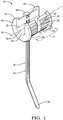
- Fig. 1 illustrates a non-limiting example of a cable-retaining-device 10, hereafter referred to as a device 10, configured to use with a robotic actuator.
- the device 10 is an improvement over other cable-retaining-devices because it does not require a robotic actuator to orient the device 10 with a unique rotation about a cable 12 (see Fig. 3 ) to install a wire-harness (not shown) onto a vehicle (not shown).
- the device 10 includes a generally cylindrically shaped body 14 defining a longitudinal-axis 16.
- the body 14 may be composed of a polymeric material, such as a polyamide.
- a mesial-portion 18 (i.e. central-portion, medial-portion, etc.) of the body 14 defines a passage 20 configured to receive the cable 12 extending longitudinally along an entire length of the body 14.
- the passage 20 may be characterized as a U-shaped 22 channel extending inwardly from the exterior-surface 42 to the mesial-portion 18.
- Other shapes of the channel are contemplated, but not shown, and include square, rectangular, and V-shaped.
- a radius (not shown) of the U-shaped 22 portion of the channel is 3.5 mm. The radius may be any radius required to receive the cable 12.
- a distal-portion 24 of the body 14 defines a slot 26 extending radially about the longitudinal-axis 16 of the body 14.
- the slot 26 may preferably be centrally located between a first-end 28 of the body 14 and a second-end 30 of the body 14, or may be offset from the central location.
- the slot 26 is preferably open to the channel and terminates at a cable-retaining-band 32, as will be explained below.
- the device 10 also includes the cable-retaining-band 32 disposed within the slot 26.
- the cable-retaining-band 32 is configured to radially encircle the device 10 to retain the cable 12.
- the cable-retaining-band 32 may be composed of a polymeric material similar to that of the body 14, and may be a cable-tie 34 having a head 36 and an elongate tail 38 extending from the head 36.
- the head 36 may be integral to the body 14 and is configured to receive a portion of the tail 38, wherein the tail 38 may be pulled through the head 36 such that the tail 38 is in forcible contact with the cable 12.
- the body 14 may include a plurality of ridges 40 extending generally parallel to the longitudinal-axis 16 along an exterior-surface 42 of the body 14.
- the plurality of ridges 40 may preferably extend beyond the exterior-surface 42 for a distance of at least 0.5 millimeters (0.5 mm).
- the plurality of ridges 40 extend for a distance of 1.0 mm beyond the exterior-surface 42 and have a peak-to-peak spacing of 2.1 mm.
- the distance that the plurality of ridges 40 extend beyond the exterior-surface 42, and the spacing of the plurality of ridges 40, may be adjusted based on an attachment-mechanism 44A-44C (see Figs. 5A-5C ) used to retain the device 10.
- the body 14 may include a first-flange 46 radially extending from the first-end 28 of the body 14 and a second-flange 48 radially extending from the second-end 30 of the body 14. Both the first-flange 46 and the second-flange 48 may extend beyond the exterior-surface 42 of the body 14 by a distance of at least 1.0 mm.
- the first-flange 46 and the second-flange 48 may have a generally disc-shaped profile or may have an angulated profile as illustrated in Fig. 1 .
- the profile may be configured to assist in a targeting of a vision-system incorporated with the robotic actuator (not shown).
- both the first-flange 46 and the second-flange 48 extend beyond the plurality of ridges 40 by a distance of approximately 1.3 mm.
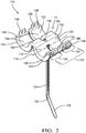
- Fig. 2 illustrates a non-limiting example of another embodiment of a cable-retaining-device 110, hereafter referred to as the device 110.
- the device 110 includes a generally cylindrically shaped body 114 defining a longitudinal-axis 116.
- the body 114 may be composed of a polymeric material, such as a polyamide.
- the body 114 has a lower-shell 152, a first-upper-shell 154 attached to the lower-shell 152 by a first-hinge 156, and a second-upper-shell 158 attached to the lower-shell 152 by a second-hinge 160.
- the lower-shell 152 defines a first-portion 162 of a passage 120, and both the first-upper-shell 154 and the second-upper-shell 158 define a second-portion 164 of the passage 120.
- Both the first-upper-shell 154 and the second-upper-shell 158 include locking-tabs 166 that engage corresponding locking-ramps 168 located on the lower-shell 152 opposite both the first-hinge 156 and opposite the second-hinge 160.
- the device 110 is configured to encase a cable 112 when the locking-tabs 166 are locked to their corresponding locking-ramps 168, as illustrated in Fig. 4 .
- a mesial-portion 118 (i.e. central-portion, medial-portion, etc.) of the body 114 defines a passage 120 configured to receive the cable 112 extending longitudinally along an entire length of the body 114.
- the passage 120 may be characterized as a cylindrical-shaped channel. Other shapes of the channel are contemplated, but not shown, and include square, rectangular, and triangular shapes. In the non-limiting example illustrated in Fig. 2 , a radius of the channel is 3.5 mm. The radius may be any radius required to receive the cable 112.
- a distal-portion 124 of the body 114 defines a slot 126 extending radially about the longitudinal-axis 116 of the body 114.
- the slot 126 extends from an exterior-surface 142 (see Fig. 4 ) of the body 114 to the passage 120.
- the slot 126 may preferably be centrally located between a first-end 128 of the body 114 and a second-end 130 of the body 114, or may be offset from the central location.
- the slot 126 is preferably open to the channel and terminates at a cable-retaining-band 132, as will be explained below.
- the body 114 may include a plurality of rectangular facets 170 on the exterior-surface 142 (see Fig. 4 ).
- a major-axis (not specifically shown) of each rectangular facet 170 is generally parallel to the longitudinal-axis 116.
- the plurality of rectangular facets 170 each have a minor-axis (not specifically shown) dimension of 2.1 mm.
- the device 110 also includes the cable-retaining-band 132 disposed within the slot 126.
- the cable-retaining-band 132 is configured to radially encircle the device 110 to retain the cable 112.
- the cable-retaining-band 132 may be composed of a polymeric material similar to that of the body 114, and may be a cable-tie 134 having a head 136 and an elongate tail 138 extending from the head 136.
- the head 136 may be integral to the body 114 and is configured to receive a portion of the tail 138, wherein the tail 138 may be pulled through the head 136 such that the tail 138 is in forcible contact with the cable 112.
- Fig. 3 illustrates a non-limiting example of a cable-assembly 50, that includes the cable 12, and the device 10 described above.
- the cable 12 may be a solid wire, a multi-strand wire, or may be a multi-wire bundled cable 12.
- the cable 12 may include an insulation layer on an outer-surface (not specifically shown).
- the cable 12 may be any diameter that may be received within the passage 20.
- the cable-assembly 50 may accept the diameter of the cable 12 in a range from about 2.0 mm to about 7.0 mm.
- the cable 12 is received within the passage 20 and the cable-retaining-band 32 encircles the device 10 to retain the cable 12 when the tail 38 is pulled through the head 36 such that the tail 38 is in forcible contact with the cable 12.
- the cable-assembly 50 may be part of a larger wiring-harness that is installed in the vehicle, which may include a plurality of the devices 10 located at various points along the wiring-harness.
- a robotic actuator may handle the cable-assembly 50 and install the wiring-harness in the vehicle using attachment-mechanisms 44A-44C illustrated in Figs. 5A-5C , respectively.
- Fig. 4A illustrates a non-limiting example of another cable-assembly 150, that includes the cable 112, and the device 110 described above.
- the cable 112 may be a solid wire, a multi-strand wire, or may be a multi-wire bundled cable 112.
- the cable 112 may include an insulation layer on an outer-surface (not specifically shown).
- the cable 112 may be any diameter that may be received within the passage 120.
- the cable-assembly 150 may accept the diameter of the cable 112 in a range from about 2.0 mm to about 7.0 mm.
- the cable 112 is received within the passage 120 and the cable-retaining-band 132 encircles the device 110 to retain the cable 112 when the tail 138 (see Fig. 4B front-view) is pulled through the head 136 (see Fig. 4C rear-view) such that the tail 138 is in forcible contact with the cable 112.
- the cable-assembly 150 may be part of a larger wiring-harness that is installed in the vehicle, which may include a plurality of the devices 110 located at various points along the wiring-harness.
- a robotic actuator may handle the cable-assembly 150 and install the wiring-harness in the vehicle using attachment-mechanisms 44A-44C illustrated in Figs. 5A-5C , respectively.
- Fig. 5A-5C illustrate attachment-mechanisms 44A-44C, respectively.
- Attachment-mechanism 44A illustrates a threaded-post attachment that engages the plurality of ridges 40 of the device 10.
- Attachment-mechanism 44B illustrates a clip attachment that engages the plurality of rectangular facets 170 of the device 110.
- Attachment-mechanism 44C illustrates an adhesive attachment that engages a portion of the plurality of rectangular facets 170 of the device 110.
- Each of the attachment-mechanisms 44A-44C may be used with each of the cable-assemblies 50-150.
- a cable-retaining-device 10 configured to use with a robotic actuator, and cable-assembly 50 is provided.
- the cable-retaining-device 10 is an improvement over other cable-retaining-devices because it does not require a robotic actuator to orient the device 10 with an unique rotation about the cable 12 to install the wire-harness onto the vehicle.
Landscapes
- Engineering & Computer Science (AREA)
- Architecture (AREA)
- Civil Engineering (AREA)
- Structural Engineering (AREA)
- Installation Of Indoor Wiring (AREA)
- Manipulator (AREA)
- Clamps And Clips (AREA)
- Insertion, Bundling And Securing Of Wires For Electric Apparatuses (AREA)
- Supports For Pipes And Cables (AREA)
- Electric Cable Arrangement Between Relatively Moving Parts (AREA)
Abstract
Description
- This disclosure generally relates to a cable-retaining-device, and more particularly relates to a cable-retaining-device configured to use with a robotic actuator.
- It is known to retain electrical wiring using a clip that is attached to a substrate. The clip may be attached to a fastener, or the clip may have an integral fastening-device, such as a "fir tree" or a "rose bud", for example. The known retaining devices require a particular orientation about a longitudinal-axis of the electrical wiring to affix the clip to the substrate, making these devices challenging for an automated assembly process. Installing a wiring-harness into a vehicle is typically a labor intensive process. The typical mounting features attached to the wiring-harness benefit from the dexterity of a human hand, especially where a rotational alignment with a mounting hole or a mounting stud is required. These alignments are challenging for a robot to perform in the same amount of time as a human.
- The subject matter discussed in the background section should not be assumed to be prior art merely as a result of its mention in the background section. Similarly, a problem mentioned in the background section or associated with the subject matter of the background section should not be assumed to have been previously recognized in the prior art. The subject matter in the background section merely represents different approaches, which in and of themselves may also be inventions.
- In accordance with one embodiment, a cable-retaining-device, configured to use with a robotic actuator, is provided. The cable-retaining-device includes a generally cylindrically shaped body defining a longitudinal-axis. A mesial-portion of the body defines a passage configured to receive a cable extending longitudinally along an entire length of the body. A distal-portion of the body defines a slot extending radially about the longitudinal-axis. The cable-retaining-device also includes a cable-retaining-band disposed within the slot configured to radially encircle the cable-retaining-device.
- The cable-retaining-band may be a cable-tie having a head and an elongate tail extending therefrom. The head is configured to receive a portion of the tail. The head may be integral to the body. The slot may extend from an exterior-surface of the body to the passage.
- The body may include a plurality of ridges extending generally parallel to the longitudinal-axis along an exterior-surface of the body. The plurality of ridges may extend beyond the exterior-surface for a distance of at least 0.5 millimeters. Alternatively or additionally, the body may include a plurality of rectangular facets on an exterior-surface. A major axis of each rectangular facet is generally parallel to the longitudinal-axis.
- The passage may be characterized as a U-shaped channel extending from the exterior-surface. Alternatively, the body may have a lower-shell, a first-upper-shell attached to the lower-shell by a first-hinge, and a second-upper-shell attached to the lower-shell by a second-hinge. The lower-shell defines a first-portion of the passage and both the first-upper-shell and the second-upper-shell define a second-portion of the passage. Both the first-upper-shell and the second-upper-shell may include locking-tabs that engage corresponding locking-ramps located on the lower-shell opposite both the first-hinge and the second-hinge.
- The body may include a first-flange radially extending from a first-end of the body and a second-flange radially extending from a second-end of the body. The first-flange and the second-flange may extend beyond an exterior-surface of the body by a distance of at least 1.0 millimeter.
- In another embodiment, a cable-assembly is provided. The cable-assembly includes a cable and a cable-retaining-device. The cable-retaining-device includes a generally cylindrically shaped body defining a longitudinal-axis. A mesial-portion of the body defines a passage configured to receive a cable extending longitudinally along an entire length of the body. A distal-portion of the body defines a slot extending radially about the longitudinal-axis. The cable-retaining-device also includes a cable-retaining-band disposed within the slot configured to radially encircle the cable-retaining-device. The cable is received within the passage.
- Further features and advantages will appear more clearly on a reading of the following detailed description of the preferred embodiment, which is given by way of non-limiting example only and with reference to the accompanying drawings.
- The present invention will now be described, by way of example with reference to the accompanying drawings, in which:
-
Fig. 1 is an illustration of a cable-retaining-device in accordance with one embodiment; -
Fig. 2 is an illustration of a cable-retaining-device in accordance with another embodiment; -
Fig. 3 is a perspective-view of an illustration of a cable-assembly with the cable-retaining-device ofFig. 1 in accordance with yet another embodiment; -
Fig. 4A is a perspective-view of an illustration of another cable-assembly with the cable-retaining-device ofFig. 2 in accordance with yet another embodiment; -
Fig. 4B is a front-view of an illustration of the cable-assembly ofFig. 4A in accordance with yet another embodiment; -
Fig. 4C is a rear-view of an illustration of the cable-assembly ofFig. 4A in accordance with yet another embodiment; -
Fig. 5A is an illustration of an attachment-mechanism that retains the cable-assembly ofFig. 3 in accordance with one embodiment; -
Fig. 5B is an illustration of another attachment-mechanism that retains the cable-assembly ofFig. 4A in accordance with another embodiment; and -
Fig. 5C is an illustration of yet another attachment-mechanism that retains the cable-assembly ofFig. 4A in accordance with yet another embodiment. - The reference numbers of similar elements in the embodiments shown in the various figures share the last two digits.
- Described herein is a cable-retaining-device for use with a robotic installation process that does not require a unique rotational alignment. In addition, the cable-retaining-device may be readily targeted by a vision system that may accompany the robotic installation process, further improving the recognition of a particular branch of a wiring-harness for robotic installation.
-
Fig. 1 illustrates a non-limiting example of a cable-retaining-device 10, hereafter referred to as adevice 10, configured to use with a robotic actuator. As will be described in more detail below, thedevice 10 is an improvement over other cable-retaining-devices because it does not require a robotic actuator to orient thedevice 10 with a unique rotation about a cable 12 (seeFig. 3 ) to install a wire-harness (not shown) onto a vehicle (not shown). Thedevice 10 includes a generally cylindrically shapedbody 14 defining a longitudinal-axis 16. Thebody 14 may be composed of a polymeric material, such as a polyamide. - A mesial-portion 18 (i.e. central-portion, medial-portion, etc.) of the
body 14 defines apassage 20 configured to receive thecable 12 extending longitudinally along an entire length of thebody 14. Thepassage 20 may be characterized as a U-shaped 22 channel extending inwardly from the exterior-surface 42 to the mesial-portion 18. Other shapes of the channel are contemplated, but not shown, and include square, rectangular, and V-shaped. In the non-limiting example illustrated inFig. 1 , a radius (not shown) of the U-shaped 22 portion of the channel is 3.5 mm. The radius may be any radius required to receive thecable 12. - A distal-
portion 24 of thebody 14 defines aslot 26 extending radially about the longitudinal-axis 16 of thebody 14. Theslot 26 may preferably be centrally located between a first-end 28 of thebody 14 and a second-end 30 of thebody 14, or may be offset from the central location. Theslot 26 is preferably open to the channel and terminates at a cable-retaining-band 32, as will be explained below. - The
device 10 also includes the cable-retaining-band 32 disposed within theslot 26. The cable-retaining-band 32 is configured to radially encircle thedevice 10 to retain thecable 12. The cable-retaining-band 32 may be composed of a polymeric material similar to that of thebody 14, and may be a cable-tie 34 having ahead 36 and anelongate tail 38 extending from thehead 36. Thehead 36 may be integral to thebody 14 and is configured to receive a portion of thetail 38, wherein thetail 38 may be pulled through thehead 36 such that thetail 38 is in forcible contact with thecable 12. - The
body 14 may include a plurality ofridges 40 extending generally parallel to the longitudinal-axis 16 along an exterior-surface 42 of thebody 14. The plurality ofridges 40 may preferably extend beyond the exterior-surface 42 for a distance of at least 0.5 millimeters (0.5 mm). In the non-limiting example illustrated inFig. 1 , the plurality ofridges 40 extend for a distance of 1.0 mm beyond the exterior-surface 42 and have a peak-to-peak spacing of 2.1 mm. The distance that the plurality ofridges 40 extend beyond the exterior-surface 42, and the spacing of the plurality ofridges 40, may be adjusted based on an attachment-mechanism 44A-44C (seeFigs. 5A-5C ) used to retain thedevice 10. - The
body 14 may include a first-flange 46 radially extending from the first-end 28 of thebody 14 and a second-flange 48 radially extending from the second-end 30 of thebody 14. Both the first-flange 46 and the second-flange 48 may extend beyond the exterior-surface 42 of thebody 14 by a distance of at least 1.0 mm. The first-flange 46 and the second-flange 48 may have a generally disc-shaped profile or may have an angulated profile as illustrated inFig. 1 . The profile may be configured to assist in a targeting of a vision-system incorporated with the robotic actuator (not shown). In the non-limiting example illustrated inFig. 1 , both the first-flange 46 and the second-flange 48 extend beyond the plurality ofridges 40 by a distance of approximately 1.3 mm. -
Fig. 2 illustrates a non-limiting example of another embodiment of a cable-retaining-device 110, hereafter referred to as thedevice 110. Thedevice 110 includes a generally cylindrically shapedbody 114 defining a longitudinal-axis 116. Thebody 114 may be composed of a polymeric material, such as a polyamide. Thebody 114 has a lower-shell 152, a first-upper-shell 154 attached to the lower-shell 152 by a first-hinge 156, and a second-upper-shell 158 attached to the lower-shell 152 by a second-hinge 160. The lower-shell 152 defines a first-portion 162 of apassage 120, and both the first-upper-shell 154 and the second-upper-shell 158 define a second-portion 164 of thepassage 120. Both the first-upper-shell 154 and the second-upper-shell 158 include locking-tabs 166 that engage corresponding locking-ramps 168 located on the lower-shell 152 opposite both the first-hinge 156 and opposite the second-hinge 160. Thedevice 110 is configured to encase acable 112 when the locking-tabs 166 are locked to their corresponding locking-ramps 168, as illustrated inFig. 4 . - Returning to
Fig. 2 , a mesial-portion 118 (i.e. central-portion, medial-portion, etc.) of thebody 114 defines apassage 120 configured to receive thecable 112 extending longitudinally along an entire length of thebody 114. Thepassage 120 may be characterized as a cylindrical-shaped channel. Other shapes of the channel are contemplated, but not shown, and include square, rectangular, and triangular shapes. In the non-limiting example illustrated inFig. 2 , a radius of the channel is 3.5 mm. The radius may be any radius required to receive thecable 112. - A distal-
portion 124 of thebody 114 defines aslot 126 extending radially about the longitudinal-axis 116 of thebody 114. Theslot 126 extends from an exterior-surface 142 (seeFig. 4 ) of thebody 114 to thepassage 120. Theslot 126 may preferably be centrally located between a first-end 128 of thebody 114 and a second-end 130 of thebody 114, or may be offset from the central location. Theslot 126 is preferably open to the channel and terminates at a cable-retaining-band 132, as will be explained below. - The
body 114 may include a plurality ofrectangular facets 170 on the exterior-surface 142 (seeFig. 4 ). A major-axis (not specifically shown) of eachrectangular facet 170 is generally parallel to the longitudinal-axis 116. In the non-limiting example illustrated inFig. 4 , the plurality ofrectangular facets 170 each have a minor-axis (not specifically shown) dimension of 2.1 mm. - The
device 110 also includes the cable-retaining-band 132 disposed within theslot 126. The cable-retaining-band 132 is configured to radially encircle thedevice 110 to retain thecable 112. The cable-retaining-band 132 may be composed of a polymeric material similar to that of thebody 114, and may be a cable-tie 134 having ahead 136 and anelongate tail 138 extending from thehead 136. Thehead 136 may be integral to thebody 114 and is configured to receive a portion of thetail 138, wherein thetail 138 may be pulled through thehead 136 such that thetail 138 is in forcible contact with thecable 112. -
Fig. 3 illustrates a non-limiting example of a cable-assembly 50, that includes thecable 12, and thedevice 10 described above. Thecable 12 may be a solid wire, a multi-strand wire, or may be a multi-wire bundledcable 12. Thecable 12 may include an insulation layer on an outer-surface (not specifically shown). Thecable 12 may be any diameter that may be received within thepassage 20. In the non-limiting example illustrated inFig. 3 , the cable-assembly 50 may accept the diameter of thecable 12 in a range from about 2.0 mm to about 7.0 mm. Thecable 12 is received within thepassage 20 and the cable-retaining-band 32 encircles thedevice 10 to retain thecable 12 when thetail 38 is pulled through thehead 36 such that thetail 38 is in forcible contact with thecable 12. The cable-assembly 50 may be part of a larger wiring-harness that is installed in the vehicle, which may include a plurality of thedevices 10 located at various points along the wiring-harness. A robotic actuator may handle the cable-assembly 50 and install the wiring-harness in the vehicle using attachment-mechanisms 44A-44C illustrated inFigs. 5A-5C , respectively. -
Fig. 4A illustrates a non-limiting example of another cable-assembly 150, that includes thecable 112, and thedevice 110 described above. Thecable 112 may be a solid wire, a multi-strand wire, or may be a multi-wire bundledcable 112. Thecable 112 may include an insulation layer on an outer-surface (not specifically shown). Thecable 112 may be any diameter that may be received within thepassage 120. In the non-limiting example illustrated inFig. 4A , the cable-assembly 150 may accept the diameter of thecable 112 in a range from about 2.0 mm to about 7.0 mm. Thecable 112 is received within thepassage 120 and the cable-retaining-band 132 encircles thedevice 110 to retain thecable 112 when the tail 138 (seeFig. 4B front-view) is pulled through the head 136 (seeFig. 4C rear-view) such that thetail 138 is in forcible contact with thecable 112. The cable-assembly 150 may be part of a larger wiring-harness that is installed in the vehicle, which may include a plurality of thedevices 110 located at various points along the wiring-harness. A robotic actuator may handle the cable-assembly 150 and install the wiring-harness in the vehicle using attachment-mechanisms 44A-44C illustrated inFigs. 5A-5C , respectively. -
Fig. 5A-5C illustrate attachment-mechanisms 44A-44C, respectively. Attachment-mechanism 44A illustrates a threaded-post attachment that engages the plurality ofridges 40 of thedevice 10. Attachment-mechanism 44B illustrates a clip attachment that engages the plurality ofrectangular facets 170 of thedevice 110. Attachment-mechanism 44C illustrates an adhesive attachment that engages a portion of the plurality ofrectangular facets 170 of thedevice 110. Each of the attachment-mechanisms 44A-44C may be used with each of the cable-assemblies 50-150. - The examples presented herein are directed to electrical-cables. However, other embodiments of the cable-retaining-
device 10 may be envisioned that are adapted for use with optical-cables or hybrid-cables including both electrical and optical-cables. Yet other embodiments of the cable-retaining-device 10, may be envisioned that are configured for installing pneumatic or hydraulic lines, or jacketed control-cables. - Accordingly, a cable-retaining-
device 10 configured to use with a robotic actuator, and cable-assembly 50 is provided. The cable-retaining-device 10 is an improvement over other cable-retaining-devices because it does not require a robotic actuator to orient thedevice 10 with an unique rotation about thecable 12 to install the wire-harness onto the vehicle. - While this invention has been described in terms of the preferred embodiments thereof, it is not intended to be so limited, but rather only to the extent set forth in the claims that follow. Moreover, the use of the terms first, second, etc. does not denote any order of importance, but rather the terms first, second, etc. are used to distinguish one element from another. Furthermore, the use of the terms a, an, etc. do not denote a limitation of quantity, but rather denote the presence of at least one of the referenced items. Additionally, directional terms such as upper, lower, etc. do not denote any particular orientation, but rather the terms upper, lower, etc. are used to distinguish one element from another and locational establish a relationship between the various elements.
Claims (11)
- A cable-retaining-device (10) configured to use with a robotic actuator, comprising:a generally cylindrically shaped body (114) defining a longitudinal-axis (116), wherein a mesial-portion (118) of the body (114) defines a passage (120) configured to receive a cable (112) extending longitudinally along an entire length of the body (114), wherein a distal-portion (124) of the body (114) defines a slot (126) extending radially about the longitudinal-axis (116); anda cable-retaining-band (132) disposed within the slot (126) configured to radially encircle the cable-retaining-device (10).
- The cable-retaining-device (10) in accordance with claim 1, wherein the cable-retaining-band (132) is a cable-tie (134) having a head (136) and an elongate tail (138) extending therefrom, said head (136) configured to receive a portion of the tail (138), wherein the head (136) is integral to the body (114).
- The cable-retaining-device (10) in accordance with any preceding claim, wherein the body (114) includes a plurality of ridges (40) extending generally parallel to the longitudinal-axis (116) along an exterior-surface (142) of the body (114).
- The cable-retaining-device (10) in accordance with claim 3, wherein the plurality of ridges (40) extend beyond the exterior-surface (142) for a distance of at least 0.5 millimeters.
- The cable-retaining-device (10) in accordance with any preceding claim, wherein the passage (120) is characterized as a u-shaped (22) channel extending from the exterior-surface (142).
- The cable-retaining-device (10) in accordance with any preceding claim, wherein the body (114) includes a first-flange (46) radially extending from a first-end (128) of the body (114) and a second-flange (48) radially extending from a second-end (130) of the body (114), wherein said first-flange (46) and said second-flange (48) extend beyond an exterior-surface (142) of the body (114) by a distance of at least 1.0 millimeters.
- The cable-retaining-device (10) in accordance with any preceding claim, wherein the body (114) has a lower-shell (152), a first-upper-shell (154) attached to the lower-shell (152) by a first-hinge (156), and a second-upper-shell (158) attached to the lower-shell (152) by a second-hinge (160), wherein the lower-shell (152) defines a first-portion (162) of the passage (120) and both the first-upper-shell (154) and the second-upper-shell (158) define a second-portion (164) of the passage (120).
- The cable-retaining-device (10) in accordance with any preceding claim, wherein the slot (126) extends from an exterior-surface (142) of the body (114) to the passage (120).
- The cable-retaining-device (10) in accordance with claim 7, wherein both the first-upper-shell (154) and the second-upper-shell (158) include locking-tabs (166) that engage corresponding locking-ramps (168) located on the lower-shell (152) opposite both the first-hinge (156) and the second-hinge (160).
- The cable-retaining-device (10) in accordance with any preceding claim, wherein the body (114) includes a plurality of rectangular facets (170) on an exterior-surface (142) and wherein a major axis of each rectangular facet (170) is generally parallel to the longitudinal-axis (116).
- A cable-assembly (150), comprising:a cable (112); andthe cable-retaining-device (10) in accordance with any preceding claim, wherein the cable (112) is received within the passage (120) and wherein the cable-retaining-band (132) encircles the cable-retaining-device (10).
Applications Claiming Priority (1)
| Application Number | Priority Date | Filing Date | Title |
|---|---|---|---|
| US15/634,291 US10186851B2 (en) | 2017-06-27 | 2017-06-27 | Cable-assembly for robotic installation |
Publications (2)
| Publication Number | Publication Date |
|---|---|
| EP3422509A1 true EP3422509A1 (en) | 2019-01-02 |
| EP3422509B1 EP3422509B1 (en) | 2021-03-24 |
Family
ID=62791502
Family Applications (1)
| Application Number | Title | Priority Date | Filing Date |
|---|---|---|---|
| EP18177626.1A Active EP3422509B1 (en) | 2017-06-27 | 2018-06-13 | Cable-assembly for robotic installation |
Country Status (5)
| Country | Link |
|---|---|
| US (1) | US10186851B2 (en) |
| EP (1) | EP3422509B1 (en) |
| JP (1) | JP6603368B2 (en) |
| KR (1) | KR102055063B1 (en) |
| CN (1) | CN109149469B (en) |
Families Citing this family (7)
| Publication number | Priority date | Publication date | Assignee | Title |
|---|---|---|---|---|
| EP3398003A1 (en) * | 2015-12-31 | 2018-11-07 | CommScope Connectivity Belgium BVBA | Cable fixation devices and methods |
| JP6626070B2 (en) * | 2017-11-10 | 2019-12-25 | 矢崎総業株式会社 | Wire harness |
| JP7461767B2 (en) * | 2020-03-25 | 2024-04-04 | 古河電気工業株式会社 | Mounting part, electric wire bundle with mounting part, wire harness, exterior wire harness, and manufacturing method of wire harness |
| JP2023071363A (en) * | 2021-11-11 | 2023-05-23 | 株式会社東芝 | Conductor connection device |
| JP7643309B2 (en) * | 2021-11-26 | 2025-03-11 | 住友電装株式会社 | Wire Harness |
| US12300407B2 (en) * | 2022-12-22 | 2025-05-13 | The Boeing Company | Connector to attach wiring to a housing |
| US20240360922A1 (en) * | 2023-04-28 | 2024-10-31 | Hellermanntyton Corporation | Cable Tie Cradle Mount Fixings |
Citations (4)
| Publication number | Priority date | Publication date | Assignee | Title |
|---|---|---|---|---|
| JP2009055679A (en) * | 2007-08-24 | 2009-03-12 | Yazaki Corp | Wire harness fixing device |
| WO2010084343A2 (en) * | 2009-01-21 | 2010-07-29 | Farrel Roy Brenner | Improvements in and relating to electrical connector housings |
| US20140069691A1 (en) * | 2012-09-12 | 2014-03-13 | Unison Industries, Llc | Mounting device and method of assembling the same |
| WO2016190581A1 (en) * | 2015-05-28 | 2016-12-01 | 석재혁 | Cable tie |
Family Cites Families (15)
| Publication number | Priority date | Publication date | Assignee | Title |
|---|---|---|---|---|
| US3889909A (en) | 1974-06-12 | 1975-06-17 | Illinois Tool Works | Wire bundle centering grommet |
| DE4204187C2 (en) * | 1992-02-13 | 1993-12-02 | Raymond A Gmbh & Co Kg | Cable duct for receiving cable bundles |
| US5354021A (en) * | 1994-01-04 | 1994-10-11 | Farrell Darvel B | An adjustable clamp |
| US5700156A (en) | 1996-07-31 | 1997-12-23 | The Whitaker Corporation | Electrical connector with wire restraint |
| JP2000152469A (en) | 1998-11-17 | 2000-05-30 | Sumitomo Wiring Syst Ltd | Protector |
| US6079673A (en) * | 1999-04-01 | 2000-06-27 | Andrew Corporation | Transmission line hanger |
| US6818830B2 (en) * | 2002-09-26 | 2004-11-16 | Panduit Corp. | H-tap compression connector |
| US6878883B1 (en) * | 2003-09-17 | 2005-04-12 | James Rauckman | Wildlife guard for electrical power distribution and substation facilities |
| JP2005263004A (en) * | 2004-03-18 | 2005-09-29 | Furukawa Electric Co Ltd:The | Flat harness fixture |
| GB0416248D0 (en) | 2004-07-20 | 2004-08-25 | Unilever Plc | Attachment means for a cosmetic dispenser |
| JP4268120B2 (en) | 2004-12-24 | 2009-05-27 | 古河電気工業株式会社 | Wire harness clamp |
| JP5729225B2 (en) * | 2011-09-08 | 2015-06-03 | 住友電装株式会社 | Clamp |
| US8991774B2 (en) * | 2011-12-22 | 2015-03-31 | Panduit Corp. | Cable tie mount |
| GB201220289D0 (en) * | 2012-11-12 | 2012-12-26 | Airbus Operations Ltd | A mount for a cable harness |
| JP6060886B2 (en) * | 2013-12-12 | 2017-01-18 | 住友電装株式会社 | Wire harness with fixing member |
-
2017
- 2017-06-27 US US15/634,291 patent/US10186851B2/en active Active
-
2018
- 2018-06-13 EP EP18177626.1A patent/EP3422509B1/en active Active
- 2018-06-22 KR KR1020180071801A patent/KR102055063B1/en active Active
- 2018-06-25 JP JP2018119770A patent/JP6603368B2/en active Active
- 2018-06-26 CN CN201810672136.5A patent/CN109149469B/en active Active
Patent Citations (4)
| Publication number | Priority date | Publication date | Assignee | Title |
|---|---|---|---|---|
| JP2009055679A (en) * | 2007-08-24 | 2009-03-12 | Yazaki Corp | Wire harness fixing device |
| WO2010084343A2 (en) * | 2009-01-21 | 2010-07-29 | Farrel Roy Brenner | Improvements in and relating to electrical connector housings |
| US20140069691A1 (en) * | 2012-09-12 | 2014-03-13 | Unison Industries, Llc | Mounting device and method of assembling the same |
| WO2016190581A1 (en) * | 2015-05-28 | 2016-12-01 | 석재혁 | Cable tie |
Also Published As
| Publication number | Publication date |
|---|---|
| US20180375306A1 (en) | 2018-12-27 |
| KR102055063B1 (en) | 2019-12-11 |
| CN109149469B (en) | 2020-08-21 |
| US10186851B2 (en) | 2019-01-22 |
| JP6603368B2 (en) | 2019-11-06 |
| KR20190001540A (en) | 2019-01-04 |
| JP2019007620A (en) | 2019-01-17 |
| CN109149469A (en) | 2019-01-04 |
| EP3422509B1 (en) | 2021-03-24 |
Similar Documents
| Publication | Publication Date | Title |
|---|---|---|
| US10186851B2 (en) | Cable-assembly for robotic installation | |
| WO2019027682A1 (en) | Cable assembly with strain relief | |
| AU2013206689B2 (en) | Electrical crimp contact device | |
| US10205266B1 (en) | Connector wire dress cover for robotic installation | |
| AU2012241568B2 (en) | Ground stabilising device | |
| US20170218593A1 (en) | Securing device | |
| US10490932B1 (en) | Connector-assembly with cavity-plug-retainer | |
| US9557509B2 (en) | Fiber optic cable external shield connector | |
| US9643544B2 (en) | Automatic transmission holding plate and wiring unit provided with same | |
| EP2787586B1 (en) | Installation assembly for bridging a cable harness or the like between two aircraft structure elements | |
| US20070066125A1 (en) | Flat flexible cable clip with locating feature | |
| EP3649702B1 (en) | Covering element for an alternator pole | |
| US6300568B1 (en) | Grommet strip bendable along orthogonally related directions | |
| KR100820765B1 (en) | Wire support member of wiring duct | |
| JP2020205733A (en) | Wiring harness | |
| KR200458499Y1 (en) | Terminal for compressing cable | |
| KR200446819Y1 (en) | A blank clip | |
| WO2025049373A3 (en) | Positioning tool for separating entwined strands | |
| JP2013158332A (en) | Bird damage preventing tool for electric wire | |
| WO2019078981A1 (en) | Wiring-harness control for robotic installation | |
| KR101881401B1 (en) | Cable Tray Fixing Device for Power Distribution | |
| NZ754495B2 (en) | Wire terminator device | |
| WO2016145474A1 (en) | Curtain systems | |
| JP2016167401A (en) | Metallic binding band, and ground connection structure employing metallic binding band |
Legal Events
| Date | Code | Title | Description |
|---|---|---|---|
| PUAI | Public reference made under article 153(3) epc to a published international application that has entered the european phase |
Free format text: ORIGINAL CODE: 0009012 |
|
| STAA | Information on the status of an ep patent application or granted ep patent |
Free format text: STATUS: THE APPLICATION HAS BEEN PUBLISHED |
|
| AK | Designated contracting states |
Kind code of ref document: A1 Designated state(s): AL AT BE BG CH CY CZ DE DK EE ES FI FR GB GR HR HU IE IS IT LI LT LU LV MC MK MT NL NO PL PT RO RS SE SI SK SM TR |
|
| AX | Request for extension of the european patent |
Extension state: BA ME |
|
| STAA | Information on the status of an ep patent application or granted ep patent |
Free format text: STATUS: REQUEST FOR EXAMINATION WAS MADE |
|
| 17P | Request for examination filed |
Effective date: 20190702 |
|
| RBV | Designated contracting states (corrected) |
Designated state(s): AL AT BE BG CH CY CZ DE DK EE ES FI FR GB GR HR HU IE IS IT LI LT LU LV MC MK MT NL NO PL PT RO RS SE SI SK SM TR |
|
| GRAP | Despatch of communication of intention to grant a patent |
Free format text: ORIGINAL CODE: EPIDOSNIGR1 |
|
| STAA | Information on the status of an ep patent application or granted ep patent |
Free format text: STATUS: GRANT OF PATENT IS INTENDED |
|
| INTG | Intention to grant announced |
Effective date: 20200619 |
|
| GRAJ | Information related to disapproval of communication of intention to grant by the applicant or resumption of examination proceedings by the epo deleted |
Free format text: ORIGINAL CODE: EPIDOSDIGR1 |
|
| STAA | Information on the status of an ep patent application or granted ep patent |
Free format text: STATUS: REQUEST FOR EXAMINATION WAS MADE |
|
| GRAS | Grant fee paid |
Free format text: ORIGINAL CODE: EPIDOSNIGR3 |
|
| STAA | Information on the status of an ep patent application or granted ep patent |
Free format text: STATUS: GRANT OF PATENT IS INTENDED |
|
| GRAP | Despatch of communication of intention to grant a patent |
Free format text: ORIGINAL CODE: EPIDOSNIGR1 |
|
| INTG | Intention to grant announced |
Effective date: 20201013 |
|
| GRAA | (expected) grant |
Free format text: ORIGINAL CODE: 0009210 |
|
| STAA | Information on the status of an ep patent application or granted ep patent |
Free format text: STATUS: THE PATENT HAS BEEN GRANTED |
|
| AK | Designated contracting states |
Kind code of ref document: B1 Designated state(s): AL AT BE BG CH CY CZ DE DK EE ES FI FR GB GR HR HU IE IS IT LI LT LU LV MC MK MT NL NO PL PT RO RS SE SI SK SM TR |
|
| REG | Reference to a national code |
Ref country code: GB Ref legal event code: FG4D |
|
| REG | Reference to a national code |
Ref country code: CH Ref legal event code: EP |
|
| REG | Reference to a national code |
Ref country code: DE Ref legal event code: R096 Ref document number: 602018014246 Country of ref document: DE |
|
| REG | Reference to a national code |
Ref country code: IE Ref legal event code: FG4D |
|
| REG | Reference to a national code |
Ref country code: AT Ref legal event code: REF Ref document number: 1375473 Country of ref document: AT Kind code of ref document: T Effective date: 20210415 |
|
| REG | Reference to a national code |
Ref country code: LT Ref legal event code: MG9D |
|
| PG25 | Lapsed in a contracting state [announced via postgrant information from national office to epo] |
Ref country code: NO Free format text: LAPSE BECAUSE OF FAILURE TO SUBMIT A TRANSLATION OF THE DESCRIPTION OR TO PAY THE FEE WITHIN THE PRESCRIBED TIME-LIMIT Effective date: 20210624 Ref country code: BG Free format text: LAPSE BECAUSE OF FAILURE TO SUBMIT A TRANSLATION OF THE DESCRIPTION OR TO PAY THE FEE WITHIN THE PRESCRIBED TIME-LIMIT Effective date: 20210624 Ref country code: FI Free format text: LAPSE BECAUSE OF FAILURE TO SUBMIT A TRANSLATION OF THE DESCRIPTION OR TO PAY THE FEE WITHIN THE PRESCRIBED TIME-LIMIT Effective date: 20210324 Ref country code: HR Free format text: LAPSE BECAUSE OF FAILURE TO SUBMIT A TRANSLATION OF THE DESCRIPTION OR TO PAY THE FEE WITHIN THE PRESCRIBED TIME-LIMIT Effective date: 20210324 Ref country code: GR Free format text: LAPSE BECAUSE OF FAILURE TO SUBMIT A TRANSLATION OF THE DESCRIPTION OR TO PAY THE FEE WITHIN THE PRESCRIBED TIME-LIMIT Effective date: 20210625 |
|
| PG25 | Lapsed in a contracting state [announced via postgrant information from national office to epo] |
Ref country code: SE Free format text: LAPSE BECAUSE OF FAILURE TO SUBMIT A TRANSLATION OF THE DESCRIPTION OR TO PAY THE FEE WITHIN THE PRESCRIBED TIME-LIMIT Effective date: 20210324 Ref country code: RS Free format text: LAPSE BECAUSE OF FAILURE TO SUBMIT A TRANSLATION OF THE DESCRIPTION OR TO PAY THE FEE WITHIN THE PRESCRIBED TIME-LIMIT Effective date: 20210324 Ref country code: LV Free format text: LAPSE BECAUSE OF FAILURE TO SUBMIT A TRANSLATION OF THE DESCRIPTION OR TO PAY THE FEE WITHIN THE PRESCRIBED TIME-LIMIT Effective date: 20210324 |
|
| REG | Reference to a national code |
Ref country code: NL Ref legal event code: MP Effective date: 20210324 |
|
| REG | Reference to a national code |
Ref country code: AT Ref legal event code: MK05 Ref document number: 1375473 Country of ref document: AT Kind code of ref document: T Effective date: 20210324 |
|
| PG25 | Lapsed in a contracting state [announced via postgrant information from national office to epo] |
Ref country code: NL Free format text: LAPSE BECAUSE OF FAILURE TO SUBMIT A TRANSLATION OF THE DESCRIPTION OR TO PAY THE FEE WITHIN THE PRESCRIBED TIME-LIMIT Effective date: 20210324 |
|
| PG25 | Lapsed in a contracting state [announced via postgrant information from national office to epo] |
Ref country code: LT Free format text: LAPSE BECAUSE OF FAILURE TO SUBMIT A TRANSLATION OF THE DESCRIPTION OR TO PAY THE FEE WITHIN THE PRESCRIBED TIME-LIMIT Effective date: 20210324 Ref country code: EE Free format text: LAPSE BECAUSE OF FAILURE TO SUBMIT A TRANSLATION OF THE DESCRIPTION OR TO PAY THE FEE WITHIN THE PRESCRIBED TIME-LIMIT Effective date: 20210324 Ref country code: CZ Free format text: LAPSE BECAUSE OF FAILURE TO SUBMIT A TRANSLATION OF THE DESCRIPTION OR TO PAY THE FEE WITHIN THE PRESCRIBED TIME-LIMIT Effective date: 20210324 Ref country code: AT Free format text: LAPSE BECAUSE OF FAILURE TO SUBMIT A TRANSLATION OF THE DESCRIPTION OR TO PAY THE FEE WITHIN THE PRESCRIBED TIME-LIMIT Effective date: 20210324 Ref country code: SM Free format text: LAPSE BECAUSE OF FAILURE TO SUBMIT A TRANSLATION OF THE DESCRIPTION OR TO PAY THE FEE WITHIN THE PRESCRIBED TIME-LIMIT Effective date: 20210324 |
|
| PG25 | Lapsed in a contracting state [announced via postgrant information from national office to epo] |
Ref country code: IS Free format text: LAPSE BECAUSE OF FAILURE TO SUBMIT A TRANSLATION OF THE DESCRIPTION OR TO PAY THE FEE WITHIN THE PRESCRIBED TIME-LIMIT Effective date: 20210724 Ref country code: PL Free format text: LAPSE BECAUSE OF FAILURE TO SUBMIT A TRANSLATION OF THE DESCRIPTION OR TO PAY THE FEE WITHIN THE PRESCRIBED TIME-LIMIT Effective date: 20210324 Ref country code: PT Free format text: LAPSE BECAUSE OF FAILURE TO SUBMIT A TRANSLATION OF THE DESCRIPTION OR TO PAY THE FEE WITHIN THE PRESCRIBED TIME-LIMIT Effective date: 20210726 Ref country code: SK Free format text: LAPSE BECAUSE OF FAILURE TO SUBMIT A TRANSLATION OF THE DESCRIPTION OR TO PAY THE FEE WITHIN THE PRESCRIBED TIME-LIMIT Effective date: 20210324 Ref country code: RO Free format text: LAPSE BECAUSE OF FAILURE TO SUBMIT A TRANSLATION OF THE DESCRIPTION OR TO PAY THE FEE WITHIN THE PRESCRIBED TIME-LIMIT Effective date: 20210324 |
|
| REG | Reference to a national code |
Ref country code: DE Ref legal event code: R097 Ref document number: 602018014246 Country of ref document: DE |
|
| PG25 | Lapsed in a contracting state [announced via postgrant information from national office to epo] |
Ref country code: MC Free format text: LAPSE BECAUSE OF FAILURE TO SUBMIT A TRANSLATION OF THE DESCRIPTION OR TO PAY THE FEE WITHIN THE PRESCRIBED TIME-LIMIT Effective date: 20210324 Ref country code: DK Free format text: LAPSE BECAUSE OF FAILURE TO SUBMIT A TRANSLATION OF THE DESCRIPTION OR TO PAY THE FEE WITHIN THE PRESCRIBED TIME-LIMIT Effective date: 20210324 Ref country code: AL Free format text: LAPSE BECAUSE OF FAILURE TO SUBMIT A TRANSLATION OF THE DESCRIPTION OR TO PAY THE FEE WITHIN THE PRESCRIBED TIME-LIMIT Effective date: 20210324 Ref country code: ES Free format text: LAPSE BECAUSE OF FAILURE TO SUBMIT A TRANSLATION OF THE DESCRIPTION OR TO PAY THE FEE WITHIN THE PRESCRIBED TIME-LIMIT Effective date: 20210324 |
|
| REG | Reference to a national code |
Ref country code: CH Ref legal event code: PL |
|
| PLBE | No opposition filed within time limit |
Free format text: ORIGINAL CODE: 0009261 |
|
| STAA | Information on the status of an ep patent application or granted ep patent |
Free format text: STATUS: NO OPPOSITION FILED WITHIN TIME LIMIT |
|
| PG25 | Lapsed in a contracting state [announced via postgrant information from national office to epo] |
Ref country code: SI Free format text: LAPSE BECAUSE OF FAILURE TO SUBMIT A TRANSLATION OF THE DESCRIPTION OR TO PAY THE FEE WITHIN THE PRESCRIBED TIME-LIMIT Effective date: 20210324 |
|
| 26N | No opposition filed |
Effective date: 20220104 |
|
| REG | Reference to a national code |
Ref country code: BE Ref legal event code: MM Effective date: 20210630 |
|
| PG25 | Lapsed in a contracting state [announced via postgrant information from national office to epo] |
Ref country code: LU Free format text: LAPSE BECAUSE OF NON-PAYMENT OF DUE FEES Effective date: 20210613 |
|
| PG25 | Lapsed in a contracting state [announced via postgrant information from national office to epo] |
Ref country code: LI Free format text: LAPSE BECAUSE OF NON-PAYMENT OF DUE FEES Effective date: 20210630 Ref country code: IE Free format text: LAPSE BECAUSE OF NON-PAYMENT OF DUE FEES Effective date: 20210613 Ref country code: CH Free format text: LAPSE BECAUSE OF NON-PAYMENT OF DUE FEES Effective date: 20210630 |
|
| PG25 | Lapsed in a contracting state [announced via postgrant information from national office to epo] |
Ref country code: IS Free format text: LAPSE BECAUSE OF FAILURE TO SUBMIT A TRANSLATION OF THE DESCRIPTION OR TO PAY THE FEE WITHIN THE PRESCRIBED TIME-LIMIT Effective date: 20210724 |
|
| PG25 | Lapsed in a contracting state [announced via postgrant information from national office to epo] |
Ref country code: BE Free format text: LAPSE BECAUSE OF NON-PAYMENT OF DUE FEES Effective date: 20210630 |
|
| PG25 | Lapsed in a contracting state [announced via postgrant information from national office to epo] |
Ref country code: IT Free format text: LAPSE BECAUSE OF FAILURE TO SUBMIT A TRANSLATION OF THE DESCRIPTION OR TO PAY THE FEE WITHIN THE PRESCRIBED TIME-LIMIT Effective date: 20210324 |
|
| P01 | Opt-out of the competence of the unified patent court (upc) registered |
Effective date: 20230424 |
|
| PG25 | Lapsed in a contracting state [announced via postgrant information from national office to epo] |
Ref country code: CY Free format text: LAPSE BECAUSE OF FAILURE TO SUBMIT A TRANSLATION OF THE DESCRIPTION OR TO PAY THE FEE WITHIN THE PRESCRIBED TIME-LIMIT Effective date: 20210324 |
|
| PG25 | Lapsed in a contracting state [announced via postgrant information from national office to epo] |
Ref country code: HU Free format text: LAPSE BECAUSE OF FAILURE TO SUBMIT A TRANSLATION OF THE DESCRIPTION OR TO PAY THE FEE WITHIN THE PRESCRIBED TIME-LIMIT; INVALID AB INITIO Effective date: 20180613 |
|
| PG25 | Lapsed in a contracting state [announced via postgrant information from national office to epo] |
Ref country code: MK Free format text: LAPSE BECAUSE OF FAILURE TO SUBMIT A TRANSLATION OF THE DESCRIPTION OR TO PAY THE FEE WITHIN THE PRESCRIBED TIME-LIMIT Effective date: 20210324 |
|
| PG25 | Lapsed in a contracting state [announced via postgrant information from national office to epo] |
Ref country code: TR Free format text: LAPSE BECAUSE OF FAILURE TO SUBMIT A TRANSLATION OF THE DESCRIPTION OR TO PAY THE FEE WITHIN THE PRESCRIBED TIME-LIMIT Effective date: 20210324 |
|
| PG25 | Lapsed in a contracting state [announced via postgrant information from national office to epo] |
Ref country code: MT Free format text: LAPSE BECAUSE OF FAILURE TO SUBMIT A TRANSLATION OF THE DESCRIPTION OR TO PAY THE FEE WITHIN THE PRESCRIBED TIME-LIMIT Effective date: 20210324 |
|
| REG | Reference to a national code |
Ref country code: DE Ref legal event code: R081 Ref document number: 602018014246 Country of ref document: DE Owner name: APTIV TECHNOLOGIES AG, CH Free format text: FORMER OWNER: APTIV TECHNOLOGIES LIMITED, ST. MICHAEL, BB |
|
| PGFP | Annual fee paid to national office [announced via postgrant information from national office to epo] |
Ref country code: DE Payment date: 20250519 Year of fee payment: 8 |
|
| PGFP | Annual fee paid to national office [announced via postgrant information from national office to epo] |
Ref country code: GB Payment date: 20250512 Year of fee payment: 8 |
|
| PGFP | Annual fee paid to national office [announced via postgrant information from national office to epo] |
Ref country code: FR Payment date: 20250513 Year of fee payment: 8 |