EP3422504A1 - Monitoring system and monitoring method - Google Patents
Monitoring system and monitoring method Download PDFInfo
- Publication number
- EP3422504A1 EP3422504A1 EP16891439.8A EP16891439A EP3422504A1 EP 3422504 A1 EP3422504 A1 EP 3422504A1 EP 16891439 A EP16891439 A EP 16891439A EP 3422504 A1 EP3422504 A1 EP 3422504A1
- Authority
- EP
- European Patent Office
- Prior art keywords
- gas
- lightning
- insulated
- lightning arrester
- arrester
- Prior art date
- Legal status (The legal status is an assumption and is not a legal conclusion. Google has not performed a legal analysis and makes no representation as to the accuracy of the status listed.)
- Granted
Links
Images





Classifications
-
- H—ELECTRICITY
- H02—GENERATION; CONVERSION OR DISTRIBUTION OF ELECTRIC POWER
- H02H—EMERGENCY PROTECTIVE CIRCUIT ARRANGEMENTS
- H02H9/00—Emergency protective circuit arrangements for limiting excess current or voltage without disconnection
- H02H9/04—Emergency protective circuit arrangements for limiting excess current or voltage without disconnection responsive to excess voltage
- H02H9/042—Emergency protective circuit arrangements for limiting excess current or voltage without disconnection responsive to excess voltage comprising means to limit the absorbed power or indicate damaged over-voltage protection device
-
- G—PHYSICS
- G01—MEASURING; TESTING
- G01R—MEASURING ELECTRIC VARIABLES; MEASURING MAGNETIC VARIABLES
- G01R31/00—Arrangements for testing electric properties; Arrangements for locating electric faults; Arrangements for electrical testing characterised by what is being tested not provided for elsewhere
- G01R31/12—Testing dielectric strength or breakdown voltage ; Testing or monitoring effectiveness or level of insulation, e.g. of a cable or of an apparatus, for example using partial discharge measurements; Electrostatic testing
- G01R31/1227—Testing dielectric strength or breakdown voltage ; Testing or monitoring effectiveness or level of insulation, e.g. of a cable or of an apparatus, for example using partial discharge measurements; Electrostatic testing of components, parts or materials
- G01R31/1236—Testing dielectric strength or breakdown voltage ; Testing or monitoring effectiveness or level of insulation, e.g. of a cable or of an apparatus, for example using partial discharge measurements; Electrostatic testing of components, parts or materials of surge arresters
-
- H—ELECTRICITY
- H01—ELECTRIC ELEMENTS
- H01T—SPARK GAPS; OVERVOLTAGE ARRESTERS USING SPARK GAPS; SPARKING PLUGS; CORONA DEVICES; GENERATING IONS TO BE INTRODUCED INTO NON-ENCLOSED GASES
- H01T1/00—Details of spark gaps
- H01T1/12—Means structurally associated with spark gap for recording operation thereof
-
- H—ELECTRICITY
- H02—GENERATION; CONVERSION OR DISTRIBUTION OF ELECTRIC POWER
- H02H—EMERGENCY PROTECTIVE CIRCUIT ARRANGEMENTS
- H02H3/00—Emergency protective circuit arrangements for automatic disconnection directly responsive to an undesired change from normal electric working condition with or without subsequent reconnection ; integrated protection
- H02H3/02—Details
- H02H3/04—Details with warning or supervision in addition to disconnection, e.g. for indicating that protective apparatus has functioned
- H02H3/048—Checking overvoltage diverters
-
- H—ELECTRICITY
- H01—ELECTRIC ELEMENTS
- H01C—RESISTORS
- H01C7/00—Non-adjustable resistors formed as one or more layers or coatings; Non-adjustable resistors made from powdered conducting material or powdered semi-conducting material with or without insulating material
- H01C7/10—Non-adjustable resistors formed as one or more layers or coatings; Non-adjustable resistors made from powdered conducting material or powdered semi-conducting material with or without insulating material voltage responsive, i.e. varistors
- H01C7/12—Overvoltage protection resistors; Arresters
-
- H—ELECTRICITY
- H01—ELECTRIC ELEMENTS
- H01T—SPARK GAPS; OVERVOLTAGE ARRESTERS USING SPARK GAPS; SPARKING PLUGS; CORONA DEVICES; GENERATING IONS TO BE INTRODUCED INTO NON-ENCLOSED GASES
- H01T1/00—Details of spark gaps
- H01T1/14—Means structurally associated with spark gap for protecting it against overload or for disconnecting it in case of failure
-
- H—ELECTRICITY
- H02—GENERATION; CONVERSION OR DISTRIBUTION OF ELECTRIC POWER
- H02B—BOARDS, SUBSTATIONS OR SWITCHING ARRANGEMENTS FOR THE SUPPLY OR DISTRIBUTION OF ELECTRIC POWER
- H02B13/00—Arrangement of switchgear in which switches are enclosed in, or structurally associated with, a casing, e.g. cubicle
- H02B13/02—Arrangement of switchgear in which switches are enclosed in, or structurally associated with, a casing, e.g. cubicle with metal casing
- H02B13/035—Gas-insulated switchgear
- H02B13/065—Means for detecting or reacting to mechanical or electrical defects
Definitions
- the present invention relates to a monitoring system and a monitoring method for monitoring degradation or breakage of a lightning arrester having been struck by lightning.
- the effective-value conversion unit 43 converts the peak value Psp of the effective gas-pressure increase value to a temperature increase value within the tank 11, 21, 31 based on heat-transfer properties and the like of the tank 11, 21, 31.
- the energy calculation unit 44 calculates the amount of lightning strike energy based on the converted temperature increase value. The calculated amount of lightning strike energy is stored in the storage unit 47.
- a degradation signal or a breakage signal is input to a display device (not illustrated).
- the display device displays information indicating degradation of the LA element 12, 22, 32 or information indicating breakage of the LA element 12, 22, 32.
- the LA elements 12, 22, and 32 are guaranteed to withstand an amount of lightning strike energy as prescribed in their applicable standards. This prescribed withstand amount of lightning strike energy is stored in the storage unit 47 as a threshold.
- Each of the LA elements 12, 22, and 32 is configured by a plurality of elements connected in series. Upon occurrence of a lightning strike, the lightning strike energy is absorbed by the elements that constitute the LA element 12, 22, 32 corresponding to the phase of the gas-insulated lightning arrester having been struck by lightning.
- the breakage determination performed by the monitoring system 100 indicates the possibility of breakage, but cannot certainly determine that the LA element 12, 22, 32 is broken. However, the breakage determination is performed with improved accuracy by eliminating the influence of change of outside-air temperature and calculating the amount of lightning strike energy.
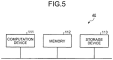
- FIG. 5 is a diagram illustrating a hardware configuration of the detection device 40 according to the first embodiment.
- the detection device 40 includes a computation device 111 that performs computation processing such as a Central Processing Unit (CPU), a volatile memory 112 that is used as a work area by the computation device 111, and a nonvolatile storage device 113 that stores therein programs, a gas pressure, a threshold, and the like.
- CPU Central Processing Unit
- volatile memory 112 that is used as a work area by the computation device 111
- nonvolatile storage device 113 that stores therein programs, a gas pressure, a threshold, and the like.
- Step S4 the gas-pressure increase value is converted to a temperature increase value (Step S4).
- the amount of lightning strike energy is calculated from the temperature increase value (Step S5).
- a breakage signal is transmitted (Step S7).
- Step S9 When the amount of lightning strike energy does not exceed the threshold used for determining breakage of the LA element 12, 22, 32 (NO at Step S6), and when a cumulative amount of lightning strike energy exceeds a threshold used for determining degradation of the LA element 12, 22, 32 (YES at Step S8), then a degradation signal is transmitted (Step S9).
- the process flow returns to Step S1 to continue monitoring of a lightning strike.
- the monitoring system detects an increase in the gas pressure within the tank 11, 21, 31 by using the sensor 15, 25, 35.
- the monitoring system calculates a temperature increase value within the tank 11, 21, 31 based on the detected gas-pressure increase value.
- the temperature within the tank 11, 21, 31 may be directly measured by the sensor 15, 25, 35.
- the sensor 15, 25, 35 detects the temperature as an internal value.
- the effective-value conversion unit 43 calculates an effective temperature increase value as an effective internal value.
- the monitoring system 100 performs both of the determination of degradation and breakage of the LA element 12, 22, 32. However, it is permissible that the monitoring system 100 is configured to perform either one of the determinations.
- the lightning-arrester operation counter 17, 27, 37 determines whether a lightning strike has occurred based on an actual magnitude of a current that flows through the ground wire 16, 26, 36.
- the monitoring system can more accurately determine the time when the gas-insulated lightning arrester has been struck by lightning. Therefore, the amount of lightning strike energy can be calculated more accurately.
- each of gas-insulated lightning arresters 301 and 302 is configured by three LA elements 12, 22, and 32 located in each of the three-phase integrated tanks 51 and 61.
- a monitoring system 300 monitors the two gas-insulated lightning arresters 301 and 302.
- a sensor 55 that detects a gas pressure in the tank 51 is provided.
- a signal output from the sensor 55 is input to a detection device 70.
- a power system has two system lines.
- three LA elements 12, 22, and 32 are also respectively arranged in the three-phase integrated tank 61.
- a sensor 65 that detects a gas pressure in the tank 61 is provided.
- a signal output from the sensor 65 is input to the detection device 70.
- Lightning-arrester operation counters 56, 57, and 58 are provided respectively on the ground wires 16, 26, and 36 extending individually from the LA elements 12, 22, and 32 arranged in the tank 51.
- Lightning-arrester operation counters 66, 67, and 68 are provided respectively on the ground wires 16, 26, and 36 extending individually from the LA elements 12, 22, and 32 arranged in the tank 61.
- the detection device 70 has the same functional configuration as the detection device 140 illustrated in FIG. 8 .
- the lightning-strike detection unit 141 Upon receiving a signal output from the lightning-arrester operation counter 56, 57, 58, 66, 67, 68, the lightning-strike detection unit 141 outputs a signal to the effective-value calculation unit 42, and stores a gas pressure in the storage unit 47.
- the gas-pressure increase value of the gas-insulated lightning arrester 301, 302 having been struck by lightning is corrected even in a case where the three-phase integrated tanks 51 and 61 are used, and thereby an actual amount of lightning strike energy can still be calculated in which the influence of outside-air temperature has been eliminated.
- the monitoring system can improve the accuracy in determining degradation or breakage of the LA element 12, 22, 32.
- the improved accuracy in determining degradation or breakage of the LA element 12, 22, 32 can suppress unnecessary replacement and maintenance of the LA elements 12, 22, and 32.
- the maintenance cost for the gas-insulated lightning arresters 301 and 302 can be reduced.
- the monitoring system may be configured to detect the temperature in the tank 51, 61 as an internal value by the sensor 55, 65.
- FIG. 10 is a configuration diagram of the monitoring system 300 according to a modification of the third embodiment.
- the ground wires 16, 26, and 36 are combined into a single ground wire 106.
- a lightning-arrester operation counter 59 is provided on the ground wire 106 connecting to the tank 51.
- a lightning-arrester operation counter 60 is provided on the ground wire 106 connecting to the tank 61.
- the lightning-arrester operation counter 59, 60 detects the operation of the LA element 12, 22, 32, and outputs a signal to the detection device 70.
- the lightning-strike detection unit 141 Upon receiving a signal output from the lightning-arrester operation counter 59, 60, the lightning-strike detection unit 141 outputs a signal to the effective-value calculation unit 42, and stores a gas pressure in the storage unit 47. Similarly to the first and second embodiments described above, after the gas-insulated lightning arrester is determined to have been struck by lightning, the lightning-strike detection unit 141 calculates the amount of lightning strike energy from which the influence of outside-air temperature has been eliminated, by subtracting the gas-pressure increase value of the tank 51, 61 not having been struck by lightning from the gas-pressure increase value of the tank 51, 61 having been struck by lightning.
- the monitoring system cannot determine exactly which of the LA elements 12, 22, and 32 is broken, but can determine in which tank 51 or 61, the LA element 12, 22, 32 is broken.
Landscapes
- Physics & Mathematics (AREA)
- General Physics & Mathematics (AREA)
- Gas-Insulated Switchgears (AREA)
Abstract
Description
- The present invention relates to a monitoring system and a monitoring method for monitoring degradation or breakage of a lightning arrester having been struck by lightning.
- A conventional monitoring system that monitors degradation or breakage of a lightning arrester calculates the amount of lightning strike energy received by a gas-insulated lightning arrester having been struck by lightning based on the temperature or pressure within a tank filled with insulating gas. The monitoring system determines the degree of degradation or breakage of the lightning arrester based on the calculated amount of lightning strike energy.
- Patent Literature 1: Japanese Patent Application Laid-open No.
2015-158455 - The conventional monitoring system described above takes into account the temperature or pressure within the tank upon occurrence of a lightning strike, but does not take into account the influence of change of outside-air temperature on the calculation. Thus, there is a problem in that the calculated amount of lightning strike energy may be different from the actual amount of lightning strike energy.
- The present invention has been achieved to solve the above problems, and an object of the present invention is to provide a monitoring system that can monitor a gas-insulated lightning arrester based on the amount of lightning strike energy which is calculated more accurately.
- In order to solve the above problems and achieve the object, a monitoring system according to the present invention monitors a plurality of gas-insulated lightning arresters, each of which is provided with a lightning arrester element within a tank filled with insulating gas, and comprises an internal-value detection unit to detect an internal value that indicates a temperature or a pressure inside the tank. The monitoring system further comprises: a lightning-strike detection unit to detect that the gas-insulated lightning arrester has been struck by lightning based on the detected internal value; an effective-value calculation unit to calculate an effective internal value by subtracting an internal value within a tank of a gas-insulated lightning arrester, determined not to have been struck by lightning, among the gas-insulated lightning arresters from an internal value within a tank of a gas-insulated lightning arrester, determined to have been struck by lightning, among the gas-insulated lightning arresters; and an energy calculation unit to calculate an amount of lightning strike energy the gas-insulated lightning arrester incurred based on the effective internal value.
- According to the monitoring system of the present invention, there is an effect where it is possible to monitor a gas-insulated lightning arrester based on the amount of lightning strike energy which is calculated more accurately.
-
-
FIG. 1 is a configuration diagram of a monitoring system according to a first embodiment of the present invention. -
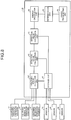
FIG. 2 is a diagram illustrating a functional configuration of a detection device according to the first embodiment. -
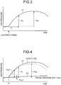
FIG. 3 is a diagram illustrating a change of gas pressure in a tank of a gas-insulated lightning arrester which has been struck by lightning according to the first embodiment. -
FIG. 4 is a diagram illustrating a change of gas pressure in the tank of the gas-insulated lightning arrester which has been struck by lightning, and a change of gas pressure in a tank of a gas-insulated lightning arrester which has not been struck by lightning according to the first embodiment. -
FIG. 5 is a diagram illustrating a hardware configuration of the detection device according to the first embodiment. -
FIG. 6 is a flowchart illustrating a procedure for determining whether a lightning arrester element is degraded or broken in the monitoring system according to the first embodiment. -
FIG. 7 is a configuration diagram of a monitoring system according to a second embodiment of the present invention. -
FIG. 8 is a diagram illustrating a functional configuration of a detection device according to the second embodiment. -
FIG. 9 is a configuration diagram of a monitoring system according to a third embodiment of the present invention. -
FIG. 10 is a configuration diagram of a monitoring system according to a modification of the third embodiment. - A monitoring system and a monitoring method according to embodiments of the present invention will be described in detail below with reference to the accompanying drawings. The present invention is not limited to the embodiments.
-
FIG. 1 is a configuration diagram of a monitoring system according to a first embodiment of the present invention. Amonitoring system 100 includes: gas-insulatedlightning arresters sensors detection device 40. The gas-insulatedlightning arresters tanks elements tanks tanks - The LA
elements tanks LA elements voltage conductors LA elements ground wires - As described above, in a three-phase power system, it is common that a gas-insulated lightning arrester is provided for each of the three phases. The
sensors lightning arresters sensors respective tanks sensors detection device 40. In the following descriptions, the pressure within thetanks -
FIG. 2 is a diagram illustrating a functional configuration of thedetection device 40 according to the first embodiment. Thedetection device 40 includes a lightning-strike detection unit 41, an effective-value calculation unit 42, an effective-value conversion unit 43, anenergy calculation unit 44, adetermination unit 45, asignal transmitting unit 46, and astorage unit 47. - The lightning-
strike detection unit 41 detects that a lightning strike has occurred on the high-voltage conductor tank sensor voltage conductors corresponding LA element lightning arrester voltage conductor LA element tank tank tank voltage conductor lightning arrester voltage conductor voltage conductor lightning arrester -
FIG. 3 is a diagram illustrating a change of gas pressure in thetank lightning arrester strike detection unit 41 calculates a difference Tp of gas pressures input from thesensor strike detection unit 41 determines that a lightning strike has occurred on the gas-insulatedlightning arrester sensor storage unit 47. The lightning-strike detection unit 41 inputs a signal indicating the gas-insulatedlightning arrester value calculation unit 42. -
FIG. 4 is a diagram illustrating a change of gas pressure in thetank lightning arrester tank lightning arrester storage unit 47 stores therein gas pressures measured in a given time period including before and after a time point at which a gas-insulated lightning arrester is determined to have been struck by lightning. The gas pressures stored in thestorage unit 47 refer to gas pressures of all the gas-insulatedlightning arresters lightning arrester storage unit 47 stores therein a gas-pressure change curve C1 of the gas-insulatedlightning arrester lightning arrester lightning arrester - Referring to the gas-pressure change curve C2 of the gas-insulated
lightning arrester lightning arrester lightning arrester lightning arrester - Thus, the effective-
value calculation unit 42 calculates a change of gas pressure of the gas-insulatedlightning arrester tank value calculation unit 42 calculates an effective increase value Pr that is an effective internal value by subtracting a gas-pressure increase value Pup2 that increases from an initial pressure P02 in the gas-insulatedlightning arrester lightning arrester
The effective increase value Pr is calculated for the entire range of gas pressure stored in thestorage unit 47. Thus, an effective change curve C10 is obtained, which is a difference between the gas-pressure change curve C1 of the gas-insulatedlightning arrester lightning arrester FIG. 3 . - The effective-
value conversion unit 43 converts the peak value Psp of the effective gas-pressure increase value to a temperature increase value within thetank tank energy calculation unit 44 calculates the amount of lightning strike energy based on the converted temperature increase value. The calculated amount of lightning strike energy is stored in thestorage unit 47. - The
determination unit 45 accumulates the previous amounts of lightning strike energy having been so far stored in thestorage unit 47, and the present amount of lightning strike energy. When the cumulative amount of lightning strike energy exceeds a predetermined threshold, thedetermination unit 45 determines that theLA element lightning arrester storage unit 47, and is derived from the capacity of theLA elements - When the amount of currently calculated lightning strike energy exceeds a predetermined threshold, the
determination unit 45 determines that theLA element lightning arrester storage unit 47. The threshold to be used for the breakage determination is smaller than the threshold to be used for the degradation determination. - The
signal transmitting unit 46 functions as a degradation-signal transmitting unit that transmits a degradation signal when theLA element LA element signal transmitting unit 46 also functions as a breakage-signal transmitting unit that transmits a breakage signal when theLA element LA element - For example, a degradation signal or a breakage signal is input to a display device (not illustrated). The display device displays information indicating degradation of the
LA element LA element - Breakage of the
LA element LA elements storage unit 47 as a threshold. Each of theLA elements LA element - When the lightning strike energy exceeds the threshold, while a part of the elements may be broken, the
LA element LA elements monitoring system 100 can still determine and detect the breakage of the any one of theLA elements - The breakage determination performed by the
monitoring system 100 indicates the possibility of breakage, but cannot certainly determine that theLA element - As described in the first embodiment, breakage determination may be performed by comparing a calculated amount of lightning strike energy with a prescribed withstand amount of lightning strike energy. The breakage determination may also be performed by calculating a pressure increase value inversely from a prescribed withstand amount of lightning strike energy, and then comparing the pressure increase values with each other. Further, the breakage determination is performed by inversely calculating a temperature increase value at the time of a lightning strike with the prescribed withstand amount of lightning strike energy, then storing the calculated temperature increase value in the
storage unit 47, and comparing the temperature increase values with each other. The same applies to degradation determination. -
FIG. 5 is a diagram illustrating a hardware configuration of thedetection device 40 according to the first embodiment. Thedetection device 40 includes acomputation device 111 that performs computation processing such as a Central Processing Unit (CPU), avolatile memory 112 that is used as a work area by thecomputation device 111, and anonvolatile storage device 113 that stores therein programs, a gas pressure, a threshold, and the like. - Individual functions of the lightning-
strike detection unit 41, the effective-value calculation unit 42, the effective-value conversion unit 43, theenergy calculation unit 44, thedetermination unit 45, and thesignal transmitting unit 46, all of which are illustrated inFIG. 2 , are implemented by thecomputation device 111 that executes programs stored in thestorage device 113. The function of thestorage unit 47 illustrated inFIG. 2 is implemented by thestorage device 113. - Next, a procedure for determining whether the
LA element monitoring system 100 according to the first embodiment is described with reference to a flowchart.FIG. 6 is a flowchart illustrating the procedure for determining whether theLA element monitoring system 100 according to the first embodiment. - In the
monitoring system 100, an increase in the gas pressure is detected (Step S1). When the gas-insulated lightning arrester101, 102, 103 is determined to have been struck by lightning based on the detected gas-pressure increase value (YES at Step S2), a gas-pressure increase value of the gas-insulatedlightning arrester lightning arrester - Next, the gas-pressure increase value is converted to a temperature increase value (Step S4). The amount of lightning strike energy is calculated from the temperature increase value (Step S5). When the amount of lightning strike energy exceeds a threshold used for determining breakage of the
LA element - When the amount of lightning strike energy does not exceed the threshold used for determining breakage of the
LA element LA element LA element - As described above, the monitoring system according to the first embodiment uses a gas-pressure increase value of the gas-insulated
lightning arrester lightning arrester LA element LA element LA elements lightning arresters - In the first embodiment, the monitoring system detects an increase in the gas pressure within the
tank sensor tank tank sensor sensor value conversion unit 43 calculates an effective temperature increase value as an effective internal value. - In the first embodiment, the
monitoring system 100 performs both of the determination of degradation and breakage of theLA element monitoring system 100 is configured to perform either one of the determinations. -
FIG. 7 is a configuration diagram of a monitoring system according to a second embodiment of the present invention. Constituent elements identical to those of the first embodiment described above are denoted by like reference signs and detailed descriptions thereof will be omitted. In amonitoring system 200 according to the second embodiment, whether a lightning strike has occurred is determined by lightning-arrester operation counters 17, 27, and 37 provided respectively on theground wires ground wire arrester operation counter LA element -
FIG. 8 is a diagram illustrating a functional configuration of adetection device 140 according to the second embodiment. In the second embodiment, the gas-insulated lightning arrester can be determined to have been struck by lightning based on a signal output from the lightning-arrester operation counter arrester operation counter strike detection unit 141 outputs a signal to the effective-value calculation unit 42, and stores a gas pressure in thestorage unit 47. After the gas-insulated lightning arrester is determined to have been struck by lightning, the effective-value calculation unit 42 and other units operate in the same manner as in the first embodiment. Thus, detailed descriptions thereof will be omitted. The hardware configuration of thedetection device 140 is identical to that of the first embodiment and thus illustrations thereof will be omitted. - In the second embodiment, the lightning-
arrester operation counter ground wire - It is permissible that the monitoring system is configured to detect the temperature in the
tank sensor -
FIG. 9 is a configuration diagram of a monitoring system according to a third embodiment of the present invention. Constituent elements identical to those of the first and second embodiments described above are denoted by like reference signs and detailed descriptions thereof will be omitted. In the first and second embodiments, the monitoring system is configured to monitor the gas-insulated lightning arresters for three phases, each of which includes a separate tank. In a lower voltage class, three-phaseintegrated tanks FIG. 9 . - In
FIG. 9 , each of gas-insulatedlightning arresters 301 and 302 is configured by threeLA elements integrated tanks monitoring system 300 monitors the two gas-insulatedlightning arresters 301 and 302. Asensor 55 that detects a gas pressure in thetank 51 is provided. A signal output from thesensor 55 is input to adetection device 70. - In general, a power system has two system lines. Thus, three
LA elements integrated tank 61. Asensor 65 that detects a gas pressure in thetank 61 is provided. A signal output from thesensor 65 is input to thedetection device 70. - Lightning-arrester operation counters 56, 57, and 58 are provided respectively on the
ground wires LA elements tank 51. Lightning-arrester operation counters 66, 67, and 68 are provided respectively on theground wires LA elements tank 61. - The
detection device 70 has the same functional configuration as thedetection device 140 illustrated inFIG. 8 . Upon receiving a signal output from the lightning-arrester operation counter strike detection unit 141 outputs a signal to the effective-value calculation unit 42, and stores a gas pressure in thestorage unit 47. Similarly to the first and second embodiments described above, after the gas-insulated lightning arrester is determined to have been struck by lightning, the lightning-strike detection unit 141 calculates the amount of lightning strike energy from which the influence of outside-air temperature has been eliminated, by subtracting a gas-pressure increase value of thetank tank - In this manner, the gas-pressure increase value of the gas-insulated
lightning arrester 301, 302 having been struck by lightning is corrected even in a case where the three-phaseintegrated tanks LA element LA element LA elements lightning arresters 301 and 302 can be reduced. - As described above in the third embodiment, even in a case where the three-phase
integrated tanks - The monitoring system may be configured to detect the temperature in the
tank sensor -
FIG. 10 is a configuration diagram of themonitoring system 300 according to a modification of the third embodiment. In the present modification, theground wires single ground wire 106. A lightning-arrester operation counter 59 is provided on theground wire 106 connecting to thetank 51. A lightning-arrester operation counter 60 is provided on theground wire 106 connecting to thetank 61. When a lightning-strike current greater than a preset magnitude flows through theground wire 106, the lightning-arrester operation counter LA element detection device 70. - Upon receiving a signal output from the lightning-
arrester operation counter strike detection unit 141 outputs a signal to the effective-value calculation unit 42, and stores a gas pressure in thestorage unit 47. Similarly to the first and second embodiments described above, after the gas-insulated lightning arrester is determined to have been struck by lightning, the lightning-strike detection unit 141 calculates the amount of lightning strike energy from which the influence of outside-air temperature has been eliminated, by subtracting the gas-pressure increase value of thetank tank - In the present modification, only a single lightning-
arrester operation counter LA elements LA elements tank LA element - In
FIG. 3 , a change of gas pressure has been described using an example in which an outside-air temperature increases after occurrence of a lightning strike. However, it is apparent that the influence of outside-air temperature can still be eliminated even when the outside-air temperature decreases. - The gas-insulated lightning arrester has been described as an example of the intended use of the present invention. However, the present invention can also be utilized for diagnosis of degradation or breakage of other elements having degradation characteristics due to the withstand energy amount.
- The configurations described in the above embodiments are only examples of the content of the present invention. The configurations can be combined with other well-known techniques, and a part of each configuration can be omitted or modified without departing from the scope of the present invention.
- 10, 20, 30 high-voltage conductor, 11, 21, 31, 51, 61 tank, 12, 22, 32 lightning arrester element, 15, 25, 35, 55, 65 sensor (internal-value detection unit), 16, 26, 36, 106 ground wire, 17, 27, 37, 56, 57, 58, 59, 60, 66, 67, 68 lightning-arrester operation counter, 40, 70, 140 detection device, 41, 141 lightning-strike detection unit, 42 effective-value calculation unit, 43 effective-value conversion unit, 44 energy calculation unit, 45 determination unit, 46 signal transmitting unit, 47 storage unit, 100, 200, 300 monitoring system, 101, 102, 103, 301, 302 gas-insulated lightning arrester, 111 computation device, 112 memory, 113 storage device.
Claims (6)
- A monitoring system to monitor a plurality of gas-insulated lightning arresters, each of which is provided with a lightning arrester element within a tank filled with insulating gas, the monitoring system comprising:an internal-value detection unit to detect an internal value that indicates a temperature or a pressure inside the tank;a lightning-strike detection unit to detect that the gas-insulated lightning arrester has been struck by lightning based on the detected internal value;an effective-value calculation unit to calculate an effective internal value by subtracting an internal value within a tank of a gas-insulated lightning arrester determined not to have been struck by lightning, among the gas-insulated lightning arresters, from an internal value within a tank of a gas-insulated lightning arrester determined to have been struck by lightning, among the gas-insulated lightning arresters; andan energy calculation unit to calculate an amount of lightning strike energy received by the gas-insulated lightning arrester from the effective internal value.
- The monitoring system according to claim 1, further comprising:a degradation determination unit to determine that the gas-insulated lightning arrester is degraded when a cumulative amount of energy obtained by accumulating a calculated amount of lightning strike energy exceeds a threshold; anda degradation signal transmitting unit to transmit a degradation signal indicating the gas-insulated lightning arrester is degraded when the gas-insulated lightning arrester is determined to be degraded.
- The monitoring system according to claim 1, further comprising:a breakage determination unit to determine that the gas-insulated lightning arrester is broken when a calculated amount of lightning strike energy exceeds a threshold; anda breakage signal transmitting unit to transmit a breakage signal indicating that the gas-insulated lightning arrester is broken when the gas-insulated lightning arrester is determined to be broken.
- A monitoring method for monitoring a plurality of gas-insulated lightning arresters, each of which is provided with a lightning arrester element within a tank filled with insulating gas, the monitoring method comprising:a step of detecting an internal value that indicates a temperature or a pressure inside the tank;a step of detecting that the gas-insulated lightning arrester has been struck by lightning based on the detected internal value;a step of calculating an effective internal value by subtracting an internal value within a tank of a gas-insulated lightning arrester determined not to have been struck by lightning, among the gas-insulated lightning arresters, from an internal value within a tank of a gas-insulated lightning arrester determined to have been struck by lightning, among the gas-insulated lightning arresters; anda step of calculating an amount of lightning strike energy received by the gas-insulated lightning arrester from the effective internal value.
- The monitoring method according to claim 4, further comprising:a step of determining that the gas-insulated lightning arrester is degraded when a cumulative amount of energy obtained by accumulating a calculated amount of lightning strike energy exceeds a threshold; anda step of transmitting a degradation signal indicating that the gas-insulated lightning arrester is degraded when the gas-insulated lightning arrester is determined to be degraded.
- The monitoring method according to claim 4, further comprising:a step of determining that the gas-insulated lightning arrester is broken when a calculated amount of lightning strike energy exceeds a threshold; anda step of transmitting a breakage signal indicating that the gas-insulated lightning arrester is broken when the gas-insulated lightning arrester is determined to be broken.
Applications Claiming Priority (1)
| Application Number | Priority Date | Filing Date | Title |
|---|---|---|---|
| PCT/JP2016/055386 WO2017145282A1 (en) | 2016-02-24 | 2016-02-24 | Monitoring system and monitoring method |
Publications (3)
| Publication Number | Publication Date |
|---|---|
| EP3422504A1 true EP3422504A1 (en) | 2019-01-02 |
| EP3422504A4 EP3422504A4 (en) | 2019-03-27 |
| EP3422504B1 EP3422504B1 (en) | 2020-02-12 |
Family
ID=59273046
Family Applications (1)
| Application Number | Title | Priority Date | Filing Date |
|---|---|---|---|
| EP16891439.8A Active EP3422504B1 (en) | 2016-02-24 | 2016-02-24 | Monitoring system and monitoring method |
Country Status (3)
| Country | Link |
|---|---|
| EP (1) | EP3422504B1 (en) |
| JP (1) | JP6157753B1 (en) |
| WO (1) | WO2017145282A1 (en) |
Cited By (3)
| Publication number | Priority date | Publication date | Assignee | Title |
|---|---|---|---|---|
| GR1009755B (en) * | 2019-10-14 | 2020-05-29 | Παναγιωτης Βασιλειου Πιττας | A multi tester for the control of multiple operational indications in lighting rods |
| CN114113835A (en) * | 2021-11-10 | 2022-03-01 | 西南交通大学 | Method for evaluating energy absorption performance of porcelain-sheathed lightning arrester under multiple lightning strike discharge |
| US12451275B2 (en) | 2020-08-25 | 2025-10-21 | Hitachi Energy Ltd | Gas insulated surge arrester and a gas insulated surge arrester monitoring system |
Family Cites Families (9)
| Publication number | Priority date | Publication date | Assignee | Title |
|---|---|---|---|---|
| JPH0246129A (en) * | 1988-08-08 | 1990-02-15 | Fuji Electric Co Ltd | System of judging abnormal temperature for electric machinery and apparatus |
| JPH042077A (en) * | 1990-04-19 | 1992-01-07 | Mitsubishi Electric Corp | Deterioration monitoring system for lightning arrester of zno type |
| JPH04206375A (en) * | 1990-11-30 | 1992-07-28 | Hitachi Ltd | Arrester degradation detector |
| JPH06201752A (en) * | 1993-01-07 | 1994-07-22 | Toshiba Corp | Gas pressure monitoring device with accident point locating function |
| JP3321480B2 (en) * | 1993-08-23 | 2002-09-03 | 株式会社東芝 | Fault location system |
| JP2000125461A (en) * | 1998-08-11 | 2000-04-28 | Hitachi Ltd | Substation system and control method thereof |
| KR100755043B1 (en) * | 2006-01-09 | 2007-09-06 | 길경석 | Arrestor diagnosis method and device by temperature measurement |
| JP2014176240A (en) * | 2013-03-11 | 2014-09-22 | Toshiba Corp | Arrestor monitoring system |
| JP6173238B2 (en) * | 2014-02-25 | 2017-08-02 | 三菱電機株式会社 | Damage detection device, damage detection system, and damage detection method |
-
2016
- 2016-02-24 WO PCT/JP2016/055386 patent/WO2017145282A1/en not_active Ceased
- 2016-02-24 EP EP16891439.8A patent/EP3422504B1/en active Active
- 2016-02-24 JP JP2016548744A patent/JP6157753B1/en active Active
Cited By (4)
| Publication number | Priority date | Publication date | Assignee | Title |
|---|---|---|---|---|
| GR1009755B (en) * | 2019-10-14 | 2020-05-29 | Παναγιωτης Βασιλειου Πιττας | A multi tester for the control of multiple operational indications in lighting rods |
| US12451275B2 (en) | 2020-08-25 | 2025-10-21 | Hitachi Energy Ltd | Gas insulated surge arrester and a gas insulated surge arrester monitoring system |
| CN114113835A (en) * | 2021-11-10 | 2022-03-01 | 西南交通大学 | Method for evaluating energy absorption performance of porcelain-sheathed lightning arrester under multiple lightning strike discharge |
| CN114113835B (en) * | 2021-11-10 | 2022-08-26 | 西南交通大学 | Method for evaluating energy absorption performance of porcelain-sheathed lightning arrester under multiple lightning strike discharge |
Also Published As
| Publication number | Publication date |
|---|---|
| WO2017145282A1 (en) | 2017-08-31 |
| EP3422504A4 (en) | 2019-03-27 |
| JPWO2017145282A1 (en) | 2018-03-01 |
| EP3422504B1 (en) | 2020-02-12 |
| JP6157753B1 (en) | 2017-07-05 |
Similar Documents
| Publication | Publication Date | Title |
|---|---|---|
| KR101946743B1 (en) | Electric motor diagnosis device | |
| KR102448292B1 (en) | battery pack diagnostic device | |
| CN106908656B (en) | Current transformer with enhanced temperature measurement | |
| EP3138171B1 (en) | Transient protection for multi-terminal hvdc grid | |
| US10295608B2 (en) | Non-intrusive correlating battery monitoring system and method | |
| EP3422504B1 (en) | Monitoring system and monitoring method | |
| CN207662966U (en) | Battery pack insulating resistor detecting circuit, battery management system and electric vehicle | |
| JP2017026559A (en) | Gas leak detection device and gas leak detection method | |
| WO2016038908A1 (en) | Gas leak detection device and gas leak inspection method | |
| CN103869179A (en) | Insulation monitoring method for direct current system | |
| US10073141B2 (en) | Detecting method and apparatus for abnormal electrical connection in main circuit of switchgear | |
| KR101151977B1 (en) | Apparatus and method for monitoring status of lightning arrester | |
| US20080157783A1 (en) | Apparatus and method for monitoring high voltage capacitors | |
| EP3830920B1 (en) | A method and a device for supervision of a voltage transformer | |
| KR101213163B1 (en) | Method and system for a analyzing failure of power line using protective relay | |
| AU2018313864B2 (en) | Rank network assets based on downstream events and measurements | |
| CN112683335A (en) | Method and device for detecting faults of transformer equipment casing | |
| JP5142783B2 (en) | Gas pressure detector for gas insulated switchgear | |
| WO2020140250A1 (en) | Apparatus and method for monitoring capacitor bank | |
| CN105937876A (en) | Transformer winding deformation detection system and method | |
| JP2024012989A (en) | Gas pressure monitoring device for gas insulated switchgear, its gas pressure monitoring method, and method for identifying gas leak location | |
| CN204758760U (en) | Current monitoring device that capacitor element punctures | |
| KR101456339B1 (en) | Relay for Detecting Under-Voltage | |
| KR101598535B1 (en) | Apparatus and method for analyzing electric power equipment | |
| KR101027816B1 (en) | Electronic electricity meter for distribution with overcurrent observing unit for detecting overcurrent in distribution system |
Legal Events
| Date | Code | Title | Description |
|---|---|---|---|
| STAA | Information on the status of an ep patent application or granted ep patent |
Free format text: STATUS: THE INTERNATIONAL PUBLICATION HAS BEEN MADE |
|
| PUAI | Public reference made under article 153(3) epc to a published international application that has entered the european phase |
Free format text: ORIGINAL CODE: 0009012 |
|
| STAA | Information on the status of an ep patent application or granted ep patent |
Free format text: STATUS: REQUEST FOR EXAMINATION WAS MADE |
|
| 17P | Request for examination filed |
Effective date: 20180814 |
|
| AK | Designated contracting states |
Kind code of ref document: A1 Designated state(s): AL AT BE BG CH CY CZ DE DK EE ES FI FR GB GR HR HU IE IS IT LI LT LU LV MC MK MT NL NO PL PT RO RS SE SI SK SM TR |
|
| AX | Request for extension of the european patent |
Extension state: BA ME |
|
| A4 | Supplementary search report drawn up and despatched |
Effective date: 20190226 |
|
| RIC1 | Information provided on ipc code assigned before grant |
Ipc: H02B 13/065 20060101AFI20190220BHEP Ipc: H02H 9/04 20060101ALI20190220BHEP Ipc: H02H 3/04 20060101ALI20190220BHEP Ipc: G01R 31/12 20060101ALI20190220BHEP Ipc: H01C 7/12 20060101ALI20190220BHEP |
|
| DAV | Request for validation of the european patent (deleted) | ||
| DAX | Request for extension of the european patent (deleted) | ||
| GRAP | Despatch of communication of intention to grant a patent |
Free format text: ORIGINAL CODE: EPIDOSNIGR1 |
|
| STAA | Information on the status of an ep patent application or granted ep patent |
Free format text: STATUS: GRANT OF PATENT IS INTENDED |
|
| INTG | Intention to grant announced |
Effective date: 20190812 |
|
| GRAS | Grant fee paid |
Free format text: ORIGINAL CODE: EPIDOSNIGR3 |
|
| GRAA | (expected) grant |
Free format text: ORIGINAL CODE: 0009210 |
|
| STAA | Information on the status of an ep patent application or granted ep patent |
Free format text: STATUS: THE PATENT HAS BEEN GRANTED |
|
| AK | Designated contracting states |
Kind code of ref document: B1 Designated state(s): AL AT BE BG CH CY CZ DE DK EE ES FI FR GB GR HR HU IE IS IT LI LT LU LV MC MK MT NL NO PL PT RO RS SE SI SK SM TR |
|
| REG | Reference to a national code |
Ref country code: GB Ref legal event code: FG4D |
|
| REG | Reference to a national code |
Ref country code: CH Ref legal event code: EP |
|
| REG | Reference to a national code |
Ref country code: AT Ref legal event code: REF Ref document number: 1233354 Country of ref document: AT Kind code of ref document: T Effective date: 20200215 |
|
| REG | Reference to a national code |
Ref country code: CH Ref legal event code: NV Representative=s name: VALIPAT S.A. C/O BOVARD SA NEUCHATEL, CH |
|
| REG | Reference to a national code |
Ref country code: IE Ref legal event code: FG4D |
|
| REG | Reference to a national code |
Ref country code: DE Ref legal event code: R096 Ref document number: 602016029855 Country of ref document: DE |
|
| PG25 | Lapsed in a contracting state [announced via postgrant information from national office to epo] |
Ref country code: FI Free format text: LAPSE BECAUSE OF FAILURE TO SUBMIT A TRANSLATION OF THE DESCRIPTION OR TO PAY THE FEE WITHIN THE PRESCRIBED TIME-LIMIT Effective date: 20200212 Ref country code: NO Free format text: LAPSE BECAUSE OF FAILURE TO SUBMIT A TRANSLATION OF THE DESCRIPTION OR TO PAY THE FEE WITHIN THE PRESCRIBED TIME-LIMIT Effective date: 20200512 Ref country code: RS Free format text: LAPSE BECAUSE OF FAILURE TO SUBMIT A TRANSLATION OF THE DESCRIPTION OR TO PAY THE FEE WITHIN THE PRESCRIBED TIME-LIMIT Effective date: 20200212 |
|
| REG | Reference to a national code |
Ref country code: LT Ref legal event code: MG4D |
|
| REG | Reference to a national code |
Ref country code: NL Ref legal event code: MP Effective date: 20200212 |
|
| PG25 | Lapsed in a contracting state [announced via postgrant information from national office to epo] |
Ref country code: GR Free format text: LAPSE BECAUSE OF FAILURE TO SUBMIT A TRANSLATION OF THE DESCRIPTION OR TO PAY THE FEE WITHIN THE PRESCRIBED TIME-LIMIT Effective date: 20200513 Ref country code: HR Free format text: LAPSE BECAUSE OF FAILURE TO SUBMIT A TRANSLATION OF THE DESCRIPTION OR TO PAY THE FEE WITHIN THE PRESCRIBED TIME-LIMIT Effective date: 20200212 Ref country code: BG Free format text: LAPSE BECAUSE OF FAILURE TO SUBMIT A TRANSLATION OF THE DESCRIPTION OR TO PAY THE FEE WITHIN THE PRESCRIBED TIME-LIMIT Effective date: 20200512 Ref country code: LV Free format text: LAPSE BECAUSE OF FAILURE TO SUBMIT A TRANSLATION OF THE DESCRIPTION OR TO PAY THE FEE WITHIN THE PRESCRIBED TIME-LIMIT Effective date: 20200212 Ref country code: SE Free format text: LAPSE BECAUSE OF FAILURE TO SUBMIT A TRANSLATION OF THE DESCRIPTION OR TO PAY THE FEE WITHIN THE PRESCRIBED TIME-LIMIT Effective date: 20200212 Ref country code: IS Free format text: LAPSE BECAUSE OF FAILURE TO SUBMIT A TRANSLATION OF THE DESCRIPTION OR TO PAY THE FEE WITHIN THE PRESCRIBED TIME-LIMIT Effective date: 20200612 |
|
| PG25 | Lapsed in a contracting state [announced via postgrant information from national office to epo] |
Ref country code: NL Free format text: LAPSE BECAUSE OF FAILURE TO SUBMIT A TRANSLATION OF THE DESCRIPTION OR TO PAY THE FEE WITHIN THE PRESCRIBED TIME-LIMIT Effective date: 20200212 |
|
| REG | Reference to a national code |
Ref country code: BE Ref legal event code: MM Effective date: 20200229 |
|
| PG25 | Lapsed in a contracting state [announced via postgrant information from national office to epo] |
Ref country code: RO Free format text: LAPSE BECAUSE OF FAILURE TO SUBMIT A TRANSLATION OF THE DESCRIPTION OR TO PAY THE FEE WITHIN THE PRESCRIBED TIME-LIMIT Effective date: 20200212 Ref country code: CZ Free format text: LAPSE BECAUSE OF FAILURE TO SUBMIT A TRANSLATION OF THE DESCRIPTION OR TO PAY THE FEE WITHIN THE PRESCRIBED TIME-LIMIT Effective date: 20200212 Ref country code: ES Free format text: LAPSE BECAUSE OF FAILURE TO SUBMIT A TRANSLATION OF THE DESCRIPTION OR TO PAY THE FEE WITHIN THE PRESCRIBED TIME-LIMIT Effective date: 20200212 Ref country code: LU Free format text: LAPSE BECAUSE OF NON-PAYMENT OF DUE FEES Effective date: 20200224 Ref country code: SK Free format text: LAPSE BECAUSE OF FAILURE TO SUBMIT A TRANSLATION OF THE DESCRIPTION OR TO PAY THE FEE WITHIN THE PRESCRIBED TIME-LIMIT Effective date: 20200212 Ref country code: PT Free format text: LAPSE BECAUSE OF FAILURE TO SUBMIT A TRANSLATION OF THE DESCRIPTION OR TO PAY THE FEE WITHIN THE PRESCRIBED TIME-LIMIT Effective date: 20200705 Ref country code: LT Free format text: LAPSE BECAUSE OF FAILURE TO SUBMIT A TRANSLATION OF THE DESCRIPTION OR TO PAY THE FEE WITHIN THE PRESCRIBED TIME-LIMIT Effective date: 20200212 Ref country code: DK Free format text: LAPSE BECAUSE OF FAILURE TO SUBMIT A TRANSLATION OF THE DESCRIPTION OR TO PAY THE FEE WITHIN THE PRESCRIBED TIME-LIMIT Effective date: 20200212 Ref country code: SM Free format text: LAPSE BECAUSE OF FAILURE TO SUBMIT A TRANSLATION OF THE DESCRIPTION OR TO PAY THE FEE WITHIN THE PRESCRIBED TIME-LIMIT Effective date: 20200212 Ref country code: EE Free format text: LAPSE BECAUSE OF FAILURE TO SUBMIT A TRANSLATION OF THE DESCRIPTION OR TO PAY THE FEE WITHIN THE PRESCRIBED TIME-LIMIT Effective date: 20200212 |
|
| REG | Reference to a national code |
Ref country code: DE Ref legal event code: R097 Ref document number: 602016029855 Country of ref document: DE |
|
| REG | Reference to a national code |
Ref country code: AT Ref legal event code: MK05 Ref document number: 1233354 Country of ref document: AT Kind code of ref document: T Effective date: 20200212 |
|
| PG25 | Lapsed in a contracting state [announced via postgrant information from national office to epo] |
Ref country code: MC Free format text: LAPSE BECAUSE OF FAILURE TO SUBMIT A TRANSLATION OF THE DESCRIPTION OR TO PAY THE FEE WITHIN THE PRESCRIBED TIME-LIMIT Effective date: 20200212 |
|
| PLBE | No opposition filed within time limit |
Free format text: ORIGINAL CODE: 0009261 |
|
| STAA | Information on the status of an ep patent application or granted ep patent |
Free format text: STATUS: NO OPPOSITION FILED WITHIN TIME LIMIT |
|
| 26N | No opposition filed |
Effective date: 20201113 |
|
| PG25 | Lapsed in a contracting state [announced via postgrant information from national office to epo] |
Ref country code: FR Free format text: LAPSE BECAUSE OF NON-PAYMENT OF DUE FEES Effective date: 20200412 Ref country code: IT Free format text: LAPSE BECAUSE OF FAILURE TO SUBMIT A TRANSLATION OF THE DESCRIPTION OR TO PAY THE FEE WITHIN THE PRESCRIBED TIME-LIMIT Effective date: 20200212 Ref country code: IE Free format text: LAPSE BECAUSE OF NON-PAYMENT OF DUE FEES Effective date: 20200224 Ref country code: AT Free format text: LAPSE BECAUSE OF FAILURE TO SUBMIT A TRANSLATION OF THE DESCRIPTION OR TO PAY THE FEE WITHIN THE PRESCRIBED TIME-LIMIT Effective date: 20200212 |
|
| PG25 | Lapsed in a contracting state [announced via postgrant information from national office to epo] |
Ref country code: PL Free format text: LAPSE BECAUSE OF FAILURE TO SUBMIT A TRANSLATION OF THE DESCRIPTION OR TO PAY THE FEE WITHIN THE PRESCRIBED TIME-LIMIT Effective date: 20200212 Ref country code: BE Free format text: LAPSE BECAUSE OF NON-PAYMENT OF DUE FEES Effective date: 20200229 Ref country code: SI Free format text: LAPSE BECAUSE OF FAILURE TO SUBMIT A TRANSLATION OF THE DESCRIPTION OR TO PAY THE FEE WITHIN THE PRESCRIBED TIME-LIMIT Effective date: 20200212 |
|
| GBPC | Gb: european patent ceased through non-payment of renewal fee |
Effective date: 20200512 |
|
| PG25 | Lapsed in a contracting state [announced via postgrant information from national office to epo] |
Ref country code: GB Free format text: LAPSE BECAUSE OF NON-PAYMENT OF DUE FEES Effective date: 20200512 |
|
| PG25 | Lapsed in a contracting state [announced via postgrant information from national office to epo] |
Ref country code: TR Free format text: LAPSE BECAUSE OF FAILURE TO SUBMIT A TRANSLATION OF THE DESCRIPTION OR TO PAY THE FEE WITHIN THE PRESCRIBED TIME-LIMIT Effective date: 20200212 Ref country code: MT Free format text: LAPSE BECAUSE OF FAILURE TO SUBMIT A TRANSLATION OF THE DESCRIPTION OR TO PAY THE FEE WITHIN THE PRESCRIBED TIME-LIMIT Effective date: 20200212 Ref country code: CY Free format text: LAPSE BECAUSE OF FAILURE TO SUBMIT A TRANSLATION OF THE DESCRIPTION OR TO PAY THE FEE WITHIN THE PRESCRIBED TIME-LIMIT Effective date: 20200212 |
|
| PG25 | Lapsed in a contracting state [announced via postgrant information from national office to epo] |
Ref country code: MK Free format text: LAPSE BECAUSE OF FAILURE TO SUBMIT A TRANSLATION OF THE DESCRIPTION OR TO PAY THE FEE WITHIN THE PRESCRIBED TIME-LIMIT Effective date: 20200212 Ref country code: AL Free format text: LAPSE BECAUSE OF FAILURE TO SUBMIT A TRANSLATION OF THE DESCRIPTION OR TO PAY THE FEE WITHIN THE PRESCRIBED TIME-LIMIT Effective date: 20200212 |
|
| REG | Reference to a national code |
Ref country code: DE Ref legal event code: R084 Ref document number: 602016029855 Country of ref document: DE |
|
| P01 | Opt-out of the competence of the unified patent court (upc) registered |
Effective date: 20230512 |
|
| REG | Reference to a national code |
Ref country code: CH Ref legal event code: U11 Free format text: ST27 STATUS EVENT CODE: U-0-0-U10-U11 (AS PROVIDED BY THE NATIONAL OFFICE) Effective date: 20260301 |
|
| PGFP | Annual fee paid to national office [announced via postgrant information from national office to epo] |
Ref country code: DE Payment date: 20260102 Year of fee payment: 11 |
|
| PGFP | Annual fee paid to national office [announced via postgrant information from national office to epo] |
Ref country code: CH Payment date: 20260301 Year of fee payment: 11 |