EP3422487A1 - Wiring-harness with connector staging device - Google Patents
Wiring-harness with connector staging device Download PDFInfo
- Publication number
- EP3422487A1 EP3422487A1 EP18178605.4A EP18178605A EP3422487A1 EP 3422487 A1 EP3422487 A1 EP 3422487A1 EP 18178605 A EP18178605 A EP 18178605A EP 3422487 A1 EP3422487 A1 EP 3422487A1
- Authority
- EP
- European Patent Office
- Prior art keywords
- electrical
- connector
- harness
- wiring
- flexible
- Prior art date
- Legal status (The legal status is an assumption and is not a legal conclusion. Google has not performed a legal analysis and makes no representation as to the accuracy of the status listed.)
- Granted
Links
Images


Classifications
-
- H—ELECTRICITY
- H01—ELECTRIC ELEMENTS
- H01R—ELECTRICALLY-CONDUCTIVE CONNECTIONS; STRUCTURAL ASSOCIATIONS OF A PLURALITY OF MUTUALLY-INSULATED ELECTRICAL CONNECTING ELEMENTS; COUPLING DEVICES; CURRENT COLLECTORS
- H01R13/00—Details of coupling devices of the kinds covered by groups H01R12/70 or H01R24/00 - H01R33/00
- H01R13/62—Means for facilitating engagement or disengagement of coupling parts or for holding them in engagement
- H01R13/629—Additional means for facilitating engagement or disengagement of coupling parts, e.g. aligning or guiding means, levers, gas pressure electrical locking indicators, manufacturing tolerances
-
- H—ELECTRICITY
- H01—ELECTRIC ELEMENTS
- H01R—ELECTRICALLY-CONDUCTIVE CONNECTIONS; STRUCTURAL ASSOCIATIONS OF A PLURALITY OF MUTUALLY-INSULATED ELECTRICAL CONNECTING ELEMENTS; COUPLING DEVICES; CURRENT COLLECTORS
- H01R13/00—Details of coupling devices of the kinds covered by groups H01R12/70 or H01R24/00 - H01R33/00
- H01R13/46—Bases; Cases
- H01R13/502—Bases; Cases composed of different pieces
-
- H—ELECTRICITY
- H01—ELECTRIC ELEMENTS
- H01R—ELECTRICALLY-CONDUCTIVE CONNECTIONS; STRUCTURAL ASSOCIATIONS OF A PLURALITY OF MUTUALLY-INSULATED ELECTRICAL CONNECTING ELEMENTS; COUPLING DEVICES; CURRENT COLLECTORS
- H01R13/00—Details of coupling devices of the kinds covered by groups H01R12/70 or H01R24/00 - H01R33/00
- H01R13/62—Means for facilitating engagement or disengagement of coupling parts or for holding them in engagement
- H01R13/629—Additional means for facilitating engagement or disengagement of coupling parts, e.g. aligning or guiding means, levers, gas pressure electrical locking indicators, manufacturing tolerances
- H01R13/631—Additional means for facilitating engagement or disengagement of coupling parts, e.g. aligning or guiding means, levers, gas pressure electrical locking indicators, manufacturing tolerances for engagement only
-
- B—PERFORMING OPERATIONS; TRANSPORTING
- B60—VEHICLES IN GENERAL
- B60R—VEHICLES, VEHICLE FITTINGS, OR VEHICLE PARTS, NOT OTHERWISE PROVIDED FOR
- B60R16/00—Electric or fluid circuits specially adapted for vehicles and not otherwise provided for; Arrangement of elements of electric or fluid circuits specially adapted for vehicles and not otherwise provided for
- B60R16/02—Electric or fluid circuits specially adapted for vehicles and not otherwise provided for; Arrangement of elements of electric or fluid circuits specially adapted for vehicles and not otherwise provided for electric constitutive elements
- B60R16/0207—Wire harnesses
- B60R16/0215—Protecting, fastening and routing means therefor
-
- H—ELECTRICITY
- H01—ELECTRIC ELEMENTS
- H01R—ELECTRICALLY-CONDUCTIVE CONNECTIONS; STRUCTURAL ASSOCIATIONS OF A PLURALITY OF MUTUALLY-INSULATED ELECTRICAL CONNECTING ELEMENTS; COUPLING DEVICES; CURRENT COLLECTORS
- H01R13/00—Details of coupling devices of the kinds covered by groups H01R12/70 or H01R24/00 - H01R33/00
- H01R13/60—Means for supporting coupling part when not engaged
-
- H—ELECTRICITY
- H01—ELECTRIC ELEMENTS
- H01R—ELECTRICALLY-CONDUCTIVE CONNECTIONS; STRUCTURAL ASSOCIATIONS OF A PLURALITY OF MUTUALLY-INSULATED ELECTRICAL CONNECTING ELEMENTS; COUPLING DEVICES; CURRENT COLLECTORS
- H01R13/00—Details of coupling devices of the kinds covered by groups H01R12/70 or H01R24/00 - H01R33/00
- H01R13/62—Means for facilitating engagement or disengagement of coupling parts or for holding them in engagement
- H01R13/639—Additional means for holding or locking coupling parts together, after engagement, e.g. separate keylock, retainer strap
-
- H—ELECTRICITY
- H01—ELECTRIC ELEMENTS
- H01R—ELECTRICALLY-CONDUCTIVE CONNECTIONS; STRUCTURAL ASSOCIATIONS OF A PLURALITY OF MUTUALLY-INSULATED ELECTRICAL CONNECTING ELEMENTS; COUPLING DEVICES; CURRENT COLLECTORS
- H01R43/00—Apparatus or processes specially adapted for manufacturing, assembling, maintaining, or repairing of line connectors or current collectors or for joining electric conductors
- H01R43/20—Apparatus or processes specially adapted for manufacturing, assembling, maintaining, or repairing of line connectors or current collectors or for joining electric conductors for assembling or disassembling contact members with insulating base, case or sleeve
-
- H—ELECTRICITY
- H01—ELECTRIC ELEMENTS
- H01R—ELECTRICALLY-CONDUCTIVE CONNECTIONS; STRUCTURAL ASSOCIATIONS OF A PLURALITY OF MUTUALLY-INSULATED ELECTRICAL CONNECTING ELEMENTS; COUPLING DEVICES; CURRENT COLLECTORS
- H01R2201/00—Connectors or connections adapted for particular applications
- H01R2201/26—Connectors or connections adapted for particular applications for vehicles
Definitions
- This disclosure generally relates to a wiring-harness, and more particularly relates to a wiring-harness having an electrical-connector staging-device.
- the typical vehicle wiring-harness may be several meters in length and may contain multiple branches that interconnect electrical components to electrical power and/or computer controllers.
- the multiple wiring-harness branches typically terminate with electrical-connectors that may be temporarily attached to the wiring-harness with adhesive tape, or other temporary attachment methods, to protect the electrical-connectors during unpacking and handling. Removal of the adhesive tape in a vehicle assembly plant is required before the wiring-harness is installed into the vehicle, and may typically be performed by a human during the installation process.
- a wiring-harness includes a wire-cable having an electrical-connector and a staging-device.
- the staging-device has a cavity defining a flexible-member in compressive contact with the electrical-connector.
- the flexible-member is configured to removably retain the electrical-connector within the cavity.
- the cavity locates the electrical-connector in a predetermined-position within the staging-device, such that the electrical-connector is presented to an assembler, e.g. a robot, in the predetermined-position.
- the flexible-member may be a arcuate flexible-beam that is integrally formed with the staging-device.
- the flexible-member may be a quarter-round ribbed-spacer that is formed of a complaint material different from a material forming the staging-device, and is disposed within a corner of the cavity.
- the flexible-member may be secured to the staging-device by a T-shaped rail defined by the flexible-member that is disposed within a corresponding T-shaped-cavity defined by the staging-device.
- At least thirty percent of a surface-area of the electrical-connector may be disposed within the cavity.
- the electrical-connector may be located with a true-position of less than 2.0 millimeters relative to the predetermined-position, and preferably with the true-position of less than 0.5 millimeter relative to the predetermined-position.
- Each cavity may include at least four datum-surfaces.
- the four datum-surfaces are configured to contact the electrical-connector disposed within the cavity on at least four corresponding datum-points.
- the at least four corresponding datum-points on the electrical-connector may include a first-side, a second-side, a third-side, and a mating-side.
- the at least four corresponding datum-points on the electrical-connector may include a first-side, a second-side, a mating-side, and a corner.
- the flexible-member may apply a retention-force to the electrical-connector within the cavity in a range from about 40 Newtons to about 60 Newtons.
- a staging-device configured to retain an electrical-connector of a wiring harness.
- the staging-device includes a staging-device-body and a flexible-member.
- the staging-device-body defines a cavity.
- the flexible-member is configured to be in compressive contact with the electrical-connector when inserted within the cavity.
- the flexible-member is configured to removably retain the electrical-connector within the cavity.
- the cavity locates the electrical-connector in a predetermined-position within the staging-device such that the electrical-connector is presented to an assembler in the predetermined-position.
- the flexible-member may be a arcuate flexible-beam that is integrally formed with the staging-device.
- the flexible-member may be a quarter-round ribbed-spacer.
- At least thirty percent of a surface-area of the electrical-connector may be disposed within the cavity.
- the electrical-connector may be located with a true-position of less than 2.0 millimeters relative to the predetermined-position.
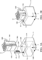
- Fig. 1 illustrates a non-limiting example of a wiring-harness 10, suitable for use in a vehicle (not shown).
- the wiring-harness 10 is an improvement over prior wiring harnesses because the wiring-harness 10 is configured to present the wiring-harness 10 to an assembler (e.g. a robot or other automated assembly process) in a repeatable and reproducible manner.
- the wiring-harness 10 includes a wire-cable 11 having an electrical-connector 12 configured to mate with a corresponding electrical-connector (not shown) that may be attached to an electrical-component on the vehicle.
- the wiring-harness 10 may have a plurality of wire-cables 11 containing a plurality of electrical-connectors 12, as will be evident to those skilled in the art.
- the plurality of electrical-connectors 12 may be of a same design, or may be of a differing designs with different dimensions.
- the wiring-harness 10 includes a staging-device 14 having a staging-device-body 15 that defines a cavity 16.
- the cavity 16 defines a flexible-member 18 in compressive contact with the electrical-connector 12 (see Figs. 2A-2B ).
- the staging-device 14 may include a single cavity 16, or may include a plurality of cavities 16 to retain the plurality of electrical-connectors 12, as illustrated in Fig 1 .
- the staging-device 14 may be attached to the wiring-harness 10, or may be attached to a wiring-conduit (not shown) in which the wiring-harness 10 may be disposed, or may be a stand-alone device.
- the flexible-member 18 is configured to removably retain the electrical-connector 12 within the cavity 16 while the wiring-harness 10 is removed from a shipping container and staged for installation onto the vehicle.
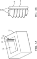
- Figs 2A-2B illustrate a top-view and a front-view, respectively, of the staging-device 14.
- the wiring-harness 10 is removed from Figs. 2A-2B for purposes of clarity.
- the flexible-member 18 may be a arcuate flexible-beam 20 that is integrally formed with the staging-device 14.
- the arcuate flexible-beam 20 may have an upper-portion and a lower-portion that may be separated by a gap.
- the arcuate flexible-beam 20 may be integrally formed with the staging-device 14, or may be removable and replaceable.
- Figs. 3A-3B illustrate another embodiment of a cavity 116 and a flexible-member 118 that is a quarter-round ribbed-spacer 22.
- a "ribbed-spacer” is commonly referred to as a "fir-tree”, “pine-tree”, and/or a "Christmas-tree” type of fastener, all of which may be included as the flexible-member 118.
- the individual ribs of the quarter-round ribbed-spacer 22 may be perpendicular to the shank or may be angled to the shank to provide an insertion lead-in for the electrical-connector 12.
- the flexible-member 118 i.e.
- the quarter-round ribbed-spacer 22 may be formed of a complaint material different from a material forming the staging-device 14.
- the quarter-round ribbed-spacer 22 may be disposed within a corner 24 of the cavity 116.
- the quarter-round ribbed-spacer 22 may be secured to the staging-device 14 by a T-shaped rail 26, defined by the flexible-member 118, that is disposed within a corresponding T-shaped-cavity 28 defined by the staging-device 14, as illustrated in Figs. 4A-4B .
- a radius of the flexible-member 118 may be varied to accommodate the electrical-connectors 12 with various dimensions without changing a dimension of the cavity 116. While the flexible-member 118 illustrated in Figs.
- 3A-4B is described as having a "quarter-round" shape, other shapes are envisioned, but not shown, that may accommodate a contour of the electrical-connector 12. This feature is beneficial because the cavity 116 may be of a standard dimension, whereas the flexible-member 118 may be fabricated to differing shapes and dimensions to retain electrical-connectors 12 of varying dimensions.
- the cavity 16 locates 30 the electrical-connector 12 in a predetermined-position 32 within the staging-device 14, such that the electrical-connector 12 is presented to the assembler in the predetermined-position 32.
- the location 30 of the electrical-connector 12, relative to an X-axis, a Y-axis, and a Z-axis of the staging-device 14 may be presented to the assembler in advance of the assembly process (i.e. downloaded into a computer memory - not shown), or may be encoded on the staging-device 14 in the form of a radiofrequency transmitter, or a bar code or other indicia (not shown) to be read by a vision system (not shown) included in the assembler.
- At least thirty percent (30%) of a surface-area of the electrical-connector 12 is disposed within the cavity 16 to maintain an alignment of the electrical-connector 12.
- the electrical-connector 12 is preferably located 30 with a true-position of less than 2.0 millimeters (2.0 mm) relative to the predetermined-position 32, and more preferably located 30 with the true-position of less than 0.5 mm.
- the true-position is an allowable tolerance window surrounding the predetermined-position 32 in which the location 30 of the electrical-connector 12 may exist.
- Each cavity 16 of the staging-device 14 may include at least four datum-surfaces 34, illustrated in Figs. 2A-2B as datum-surfaces 34A-34D, that are configured to contact the electrical-connector 12 disposed within the cavity 16 on at least four corresponding datum-points 36, illustrated in Figs. 2A-2B as corresponding datum-points 36A-36D.
- the four corresponding datum-points 36 on the electrical-connector 12 include a first-side 36A, a second-side 36B adjacent to the first-side 36A, a third-side 36C opposite the first-side 36A, and a mating-side 36D or terminal-end of the electrical-connector 12 that lies in a plane perpendicular to the Z-axis of the staging-device 14.
- the corresponding datum-points 36 may contact the datum-surfaces 34 anywhere on the datum-surface 34, and may vary due to part-to-part dimensional variation. In other words, the exact point of contact between the corresponding datum-point 36 and the datum-surface 34 may vary.
- the cavity 116 also includes at least four datum-surfaces 134, illustrated as datum-surfaces 134A-134B and 134D-134E, and at least four corresponding datum-points 136 on the electrical-connector 12 illustrated as datum-points 136A-136B and 136D-136E.
- the at least four corresponding datum-points 136 include a first-side 136A, a second-side 136B adjacent to the first-side 136A, a mating-side 136D or terminal-end that lies in a plane perpendicular the Z-axis of the staging-device 14, and an edge 136E opposite an intersection of the first-side 136A with the second-side 136B.
- the flexible-member 18 applies a retention-force (not shown) to the electrical-connector 12 within the cavity 16 in a range from about 40 Newtons (40 N) to about 60 N.
- This retention-force is sufficient to retain the electrical-connector 12 within the cavity 16 during shipping and handling and ensures the electrical-connector 12 is located 30 at the predetermined-position 32 until the assembler removes the electrical-connector 12 from the staging-device 14.
- staging-device 14 may be envisioned that are adapted for use with optical-cables or hybrid-cables including both electrical and optical-cables. Yet other embodiments of the staging-device 14, may be envisioned that are configured for installing pneumatic or hydraulic lines.
- a wiring-harness 10 and a staging-device 14 for the wiring-harness 10 is provided.
- the wiring-harness 10 is beneficial because it is configured to present the electrical-connector 12 to the assembler (e.g. a robot or other automated assembly process) in the predetermined-position 32, which reduces an installation time required to install the wiring-harness 10 onto the vehicle and allowing easier automation of the installation process since removal of adhesive tape is no longer required to secure the connectors.
Landscapes
- Engineering & Computer Science (AREA)
- Manufacturing & Machinery (AREA)
- Mechanical Engineering (AREA)
- Details Of Connecting Devices For Male And Female Coupling (AREA)
- Insulated Conductors (AREA)
- Electric Cable Arrangement Between Relatively Moving Parts (AREA)
- Installation Of Indoor Wiring (AREA)
Abstract
Description
- This disclosure generally relates to a wiring-harness, and more particularly relates to a wiring-harness having an electrical-connector staging-device.
- The typical vehicle wiring-harness may be several meters in length and may contain multiple branches that interconnect electrical components to electrical power and/or computer controllers. The multiple wiring-harness branches typically terminate with electrical-connectors that may be temporarily attached to the wiring-harness with adhesive tape, or other temporary attachment methods, to protect the electrical-connectors during unpacking and handling. Removal of the adhesive tape in a vehicle assembly plant is required before the wiring-harness is installed into the vehicle, and may typically be performed by a human during the installation process.
- As assembly vehicle processes are increasingly automated, there may be a desire to use a robotic installer for installing a wire harness within the vehicle. However, in order to do this, a robotic assembler must be able to consistently located the multiple connectors on the harness and remove the adhesive tape. These are both fairly complex operations for a robot.
- Therefore, a vehicle wiring-harness that is configured to be more easily handled by a robotic installer remains desired.
- The subject matter discussed in the background section should not be assumed to be prior art merely as a result of its mention in the background section. Similarly, a problem mentioned in the background section or associated with the subject matter of the background section should not be assumed to have been previously recognized in the prior art. The subject matter in the background section merely represents different approaches, which in and of themselves may also be inventions.
- In accordance with one embodiment, a wiring-harness is provided. The wiring-harness includes a wire-cable having an electrical-connector and a staging-device. The staging-device has a cavity defining a flexible-member in compressive contact with the electrical-connector. The flexible-member is configured to removably retain the electrical-connector within the cavity. The cavity locates the electrical-connector in a predetermined-position within the staging-device, such that the electrical-connector is presented to an assembler, e.g. a robot, in the predetermined-position.
- The flexible-member may be a arcuate flexible-beam that is integrally formed with the staging-device.
- The flexible-member may be a quarter-round ribbed-spacer that is formed of a complaint material different from a material forming the staging-device, and is disposed within a corner of the cavity. The flexible-member may be secured to the staging-device by a T-shaped rail defined by the flexible-member that is disposed within a corresponding T-shaped-cavity defined by the staging-device.
- At least thirty percent of a surface-area of the electrical-connector may be disposed within the cavity.
- The electrical-connector may be located with a true-position of less than 2.0 millimeters relative to the predetermined-position, and preferably with the true-position of less than 0.5 millimeter relative to the predetermined-position.
- Each cavity may include at least four datum-surfaces. The four datum-surfaces are configured to contact the electrical-connector disposed within the cavity on at least four corresponding datum-points. The at least four corresponding datum-points on the electrical-connector may include a first-side, a second-side, a third-side, and a mating-side. Alternatively, the at least four corresponding datum-points on the electrical-connector may include a first-side, a second-side, a mating-side, and a corner.
- The flexible-member may apply a retention-force to the electrical-connector within the cavity in a range from about 40 Newtons to about 60 Newtons.
- In another embodiment, a staging-device configured to retain an electrical-connector of a wiring harness is provided. The staging-device includes a staging-device-body and a flexible-member. The staging-device-body defines a cavity. The flexible-member is configured to be in compressive contact with the electrical-connector when inserted within the cavity. The flexible-member is configured to removably retain the electrical-connector within the cavity. The cavity locates the electrical-connector in a predetermined-position within the staging-device such that the electrical-connector is presented to an assembler in the predetermined-position.
- The flexible-member may be a arcuate flexible-beam that is integrally formed with the staging-device.
- The flexible-member may be a quarter-round ribbed-spacer.
- At least thirty percent of a surface-area of the electrical-connector may be disposed within the cavity.
- The electrical-connector may be located with a true-position of less than 2.0 millimeters relative to the predetermined-position.
- Further features and advantages will appear more clearly on a reading of the following detailed description of the preferred embodiment, which is given by way of non-limiting example only and with reference to the accompanying drawings.
- The present invention will now be described, by way of example with reference to the accompanying drawings, in which:
-
Fig. 1 is an illustration of a wiring-harness with a staging-device in accordance with an embodiment of the invention; -
Fig. 2A is an illustration of a top-view of the staging-device ofFig. 1 in accordance with an embodiment of the invention; -
Fig. 2B is an illustration of a front-view of the staging-device ofFig. 1 in accordance with an embodiment of the invention; -
Fig. 3A is an illustration of an exploded-view of a cavity, a flexible-member, and an electrical-connector in accordance with an embodiment of the invention; -
Fig. 3B is an illustration of a perspective-view of the cavity, the flexible-member, and the electrical-connector ofFig. 3A in accordance with an embodiment of the invention; -
Fig. 4A is an illustration of the cavity ofFig. 3A in accordance with an embodiment of the invention; and -
Fig. 4B is an illustration of the flexible-member ofFigs. 3A-3B in accordance with an embodiment of the invention. - The reference numbers of similar elements in the various embodiments shown in the figures share the last two digits.
-
Fig. 1 illustrates a non-limiting example of a wiring-harness 10, suitable for use in a vehicle (not shown). As will be described in more detail below, the wiring-harness 10 is an improvement over prior wiring harnesses because the wiring-harness 10 is configured to present the wiring-harness 10 to an assembler (e.g. a robot or other automated assembly process) in a repeatable and reproducible manner. The wiring-harness 10 includes a wire-cable 11 having an electrical-connector 12 configured to mate with a corresponding electrical-connector (not shown) that may be attached to an electrical-component on the vehicle. The wiring-harness 10 may have a plurality of wire-cables 11 containing a plurality of electrical-connectors 12, as will be evident to those skilled in the art. The plurality of electrical-connectors 12 may be of a same design, or may be of a differing designs with different dimensions. - The wiring-
harness 10 includes a staging-device 14 having a staging-device-body 15 that defines acavity 16. Thecavity 16 defines a flexible-member 18 in compressive contact with the electrical-connector 12 (seeFigs. 2A-2B ). The staging-device 14 may include asingle cavity 16, or may include a plurality ofcavities 16 to retain the plurality of electrical-connectors 12, as illustrated inFig 1 . The staging-device 14 may be attached to the wiring-harness 10, or may be attached to a wiring-conduit (not shown) in which the wiring-harness 10 may be disposed, or may be a stand-alone device. The flexible-member 18 is configured to removably retain the electrical-connector 12 within thecavity 16 while the wiring-harness 10 is removed from a shipping container and staged for installation onto the vehicle. -
Figs 2A-2B illustrate a top-view and a front-view, respectively, of the staging-device 14. The wiring-harness 10 is removed fromFigs. 2A-2B for purposes of clarity. The flexible-member 18 may be a arcuate flexible-beam 20 that is integrally formed with the staging-device 14. The arcuate flexible-beam 20 may have an upper-portion and a lower-portion that may be separated by a gap. The arcuate flexible-beam 20 may be integrally formed with the staging-device 14, or may be removable and replaceable. -
Figs. 3A-3B illustrate another embodiment of acavity 116 and a flexible-member 118 that is a quarter-round ribbed-spacer 22. A "ribbed-spacer" is commonly referred to as a "fir-tree", "pine-tree", and/or a "Christmas-tree" type of fastener, all of which may be included as the flexible-member 118. The individual ribs of the quarter-round ribbed-spacer 22 may be perpendicular to the shank or may be angled to the shank to provide an insertion lead-in for the electrical-connector 12. The flexible-member 118 (i.e. the quarter-round ribbed-spacer 22) may be formed of a complaint material different from a material forming the staging-device 14. The quarter-round ribbed-spacer 22 may be disposed within acorner 24 of thecavity 116. The quarter-round ribbed-spacer 22 may be secured to the staging-device 14 by a T-shapedrail 26, defined by the flexible-member 118, that is disposed within a corresponding T-shaped-cavity 28 defined by the staging-device 14, as illustrated inFigs. 4A-4B . A radius of the flexible-member 118 may be varied to accommodate the electrical-connectors 12 with various dimensions without changing a dimension of thecavity 116. While the flexible-member 118 illustrated inFigs. 3A-4B is described as having a "quarter-round" shape, other shapes are envisioned, but not shown, that may accommodate a contour of the electrical-connector 12. This feature is beneficial because thecavity 116 may be of a standard dimension, whereas the flexible-member 118 may be fabricated to differing shapes and dimensions to retain electrical-connectors 12 of varying dimensions. - Returning now to
Figs. 2A-2B , thecavity 16 locates 30 the electrical-connector 12 in a predetermined-position 32 within the staging-device 14, such that the electrical-connector 12 is presented to the assembler in the predetermined-position 32. Thelocation 30 of the electrical-connector 12, relative to an X-axis, a Y-axis, and a Z-axis of the staging-device 14 may be presented to the assembler in advance of the assembly process (i.e. downloaded into a computer memory - not shown), or may be encoded on the staging-device 14 in the form of a radiofrequency transmitter, or a bar code or other indicia (not shown) to be read by a vision system (not shown) included in the assembler. - Preferably, at least thirty percent (30%) of a surface-area of the electrical-
connector 12 is disposed within thecavity 16 to maintain an alignment of the electrical-connector 12. The electrical-connector 12 is preferably located 30 with a true-position of less than 2.0 millimeters (2.0 mm) relative to the predetermined-position 32, and more preferably located 30 with the true-position of less than 0.5 mm. As used herein, the true-position is an allowable tolerance window surrounding the predetermined-position 32 in which thelocation 30 of the electrical-connector 12 may exist. - Each
cavity 16 of the staging-device 14 may include at least four datum-surfaces 34, illustrated inFigs. 2A-2B as datum-surfaces 34A-34D, that are configured to contact the electrical-connector 12 disposed within thecavity 16 on at least four corresponding datum-points 36, illustrated inFigs. 2A-2B as corresponding datum-points 36A-36D. The four corresponding datum-points 36 on the electrical-connector 12 include a first-side 36A, a second-side 36B adjacent to the first-side 36A, a third-side 36C opposite the first-side 36A, and a mating-side 36D or terminal-end of the electrical-connector 12 that lies in a plane perpendicular to the Z-axis of the staging-device 14. One skilled in the art of will recognize that the corresponding datum-points 36 may contact the datum-surfaces 34 anywhere on the datum-surface 34, and may vary due to part-to-part dimensional variation. In other words, the exact point of contact between the corresponding datum-point 36 and the datum-surface 34 may vary. - For the specific example of the
cavity 116 with the quarter-round ribbed-spacer 22 illustrated inFigs. 3A-3B , thecavity 116 also includes at least four datum-surfaces 134, illustrated as datum-surfaces 134A-134B and 134D-134E, and at least four corresponding datum-points 136 on the electrical-connector 12 illustrated as datum-points 136A-136B and 136D-136E. The at least four corresponding datum-points 136 include a first-side 136A, a second-side 136B adjacent to the first-side 136A, a mating-side 136D or terminal-end that lies in a plane perpendicular the Z-axis of the staging-device 14, and anedge 136E opposite an intersection of the first-side 136A with the second-side 136B. - Returning again to
Figs. 2A-2B , the flexible-member 18 applies a retention-force (not shown) to the electrical-connector 12 within thecavity 16 in a range from about 40 Newtons (40 N) to about 60 N. This retention-force is sufficient to retain the electrical-connector 12 within thecavity 16 during shipping and handling and ensures the electrical-connector 12 is located 30 at the predetermined-position 32 until the assembler removes the electrical-connector 12 from the staging-device 14. - The examples presented herein are directed to electrical-cables. However, other embodiments of the staging-
device 14 may be envisioned that are adapted for use with optical-cables or hybrid-cables including both electrical and optical-cables. Yet other embodiments of the staging-device 14, may be envisioned that are configured for installing pneumatic or hydraulic lines. - Accordingly, a wiring-
harness 10 and a staging-device 14 for the wiring-harness 10 is provided. The wiring-harness 10 is beneficial because it is configured to present the electrical-connector 12 to the assembler (e.g. a robot or other automated assembly process) in the predetermined-position 32, which reduces an installation time required to install the wiring-harness 10 onto the vehicle and allowing easier automation of the installation process since removal of adhesive tape is no longer required to secure the connectors. - While this invention has been described in terms of the preferred embodiments thereof, it is not intended to be so limited, but rather only to the extent set forth in the claims that follow. Moreover, the use of the terms first, second, upper, lower, etc. does not denote any order of importance, location, or orientation, but rather the terms first, second, etc. are used to distinguish one element from another. Furthermore, the use of the terms a, an, etc. do not denote a limitation of quantity, but rather denote the presence of at least one of the referenced items.
Claims (15)
- A wiring-harness (10), comprising:a wire-cable (11) having an electrical-connector (12); anda staging-device (14) having a cavity (16) defining a flexible-member (18) in compressive contact with the electrical-connector (12), said flexible-member (18) configured to removably retain the electrical-connector (12) within the cavity (16), wherein the cavity (16) locates the electrical-connector (12) in a predetermined-position (32) within the staging-device (14), such that the electrical-connector (12) is presented to an assembler in the predetermined-position (32).
- The wiring-harness (10) in accordance with claim 1, wherein the flexible-member (18) is a arcuate flexible-beam (20).
- The wiring-harness (10) in accordance with claim 2, wherein the arcuate flexible-beam (20) is integrally formed with the staging-device (14).
- The wiring-harness (10) in accordance with claim 1, wherein the flexible-member (18) is a quarter-round ribbed-spacer (22).
- The wiring-harness (10) in accordance with claim 4, wherein the flexible-member (18) is formed of a complaint material different from a material forming the staging-device (14).
- The wiring-harness (10) in accordance with any preceding claim, wherein the flexible-member (18) is disposed within a corner (24) of the cavity (16).
- The wiring-harness (10) in accordance with any preceding claim, wherein the flexible-member (18) is secured to the staging-device (14) by a t-shaped rail (26) defined by the flexible-member (18) that is disposed within a corresponding t-shaped-cavity (28) defined by the staging-device (14).
- The wiring-harness (10) in accordance with any preceding claim, wherein at least thirty percent of a surface-area of the electrical-connector (12) is disposed within the cavity (16).
- The wiring-harness (10) in accordance with any preceding claim, wherein the electrical-connector (12) is located with a true-position of less than 2.0 millimeters relative to the predetermined-position (32).
- The wiring-harness (10) in accordance with claim 9, wherein the electrical-connector (12) is located with the true-position of less than 0.5 millimeter relative to the predetermined-position (32).
- The wiring-harness (10) in accordance with any preceding claim, wherein each cavity (16) includes at least four datum-surfaces (34), said four datum-surfaces (34) configured to contact the electrical-connector (12) disposed within the cavity (16) on at least four corresponding datum-points (36).
- The wiring-harness (10) in accordance with claim 11, wherein the at least four corresponding datum-points (36) on the electrical-connector (12) include a first-side (36A), a second-side (36B), a third-side (36C), and a mating-side (36D).
- The wiring-harness (10) in accordance with claim 11, wherein the at least four corresponding datum-points (36) on the electrical-connector (12) include a first-side (36A), a second-side (36B), a mating-side (36D), and a corner (24).
- The wiring-harness (10) in accordance with any preceding claim, wherein the flexible-member (18) applies a retention-force to the electrical-connector (12) within the cavity (16) in a range from about 40 newtons to about 60 newtons.
- The wiring-harness (10) in accordance with any preceding claim, wherein the assembler is a robot.
Applications Claiming Priority (1)
| Application Number | Priority Date | Filing Date | Title |
|---|---|---|---|
| US15/634,268 US10355409B2 (en) | 2017-06-27 | 2017-06-27 | Wiring-harness with connector staging device |
Publications (2)
| Publication Number | Publication Date |
|---|---|
| EP3422487A1 true EP3422487A1 (en) | 2019-01-02 |
| EP3422487B1 EP3422487B1 (en) | 2021-06-09 |
Family
ID=62712904
Family Applications (1)
| Application Number | Title | Priority Date | Filing Date |
|---|---|---|---|
| EP18178605.4A Active EP3422487B1 (en) | 2017-06-27 | 2018-06-19 | Wiring-harness with connector staging device |
Country Status (5)
| Country | Link |
|---|---|
| US (2) | US10355409B2 (en) |
| EP (1) | EP3422487B1 (en) |
| JP (1) | JP6873945B2 (en) |
| KR (1) | KR102032058B1 (en) |
| CN (1) | CN109149222B (en) |
Cited By (1)
| Publication number | Priority date | Publication date | Assignee | Title |
|---|---|---|---|---|
| EP3846292A1 (en) * | 2020-01-03 | 2021-07-07 | Aptiv Technologies Limited | Staging system for robotic installation of connectors and method for robotic installation of a conductor assembly including connectors |
Families Citing this family (8)
| Publication number | Priority date | Publication date | Assignee | Title |
|---|---|---|---|---|
| JP6838711B2 (en) * | 2017-10-16 | 2021-03-03 | 住友電装株式会社 | Wire harness connection structure to two circuits |
| JP6936970B2 (en) * | 2017-10-16 | 2021-09-22 | 住友電装株式会社 | Wire harness connection structure to the circuit inside the housing |
| JP2020150774A (en) * | 2019-03-15 | 2020-09-17 | 株式会社オートネットワーク技術研究所 | Vehicle wire harness |
| US10550541B1 (en) * | 2019-04-25 | 2020-02-04 | Deere & Company | Connection system for connecting an implement to a work vehicle |
| US11888262B2 (en) | 2020-01-03 | 2024-01-30 | Aptiv Technologies Limited | Automotive electrical connector features for robotic installation |
| DE102023000161B3 (en) | 2023-01-19 | 2024-03-28 | Mercedes-Benz Group AG | Device and method for assembling several cable harness components at a remote point |
| US20240291199A1 (en) * | 2023-02-23 | 2024-08-29 | Aptiv Technologies AG | Self-aligning modular electrical connection system with a common carrier |
| US20250357708A1 (en) * | 2024-05-14 | 2025-11-20 | Aptiv Technologies AG | Connector Staging System and Method |
Citations (4)
| Publication number | Priority date | Publication date | Assignee | Title |
|---|---|---|---|---|
| AU8399175A (en) * | 1974-08-16 | 1977-02-17 | Australian Power And Distribut | Distribution termination panel |
| JPH07130449A (en) * | 1993-11-02 | 1995-05-19 | Yazaki Corp | Connector receiving jig |
| JPH08298024A (en) * | 1995-04-26 | 1996-11-12 | Sumitomo Wiring Syst Ltd | Flat harness |
| US5964617A (en) * | 1998-03-06 | 1999-10-12 | Whirlpool Corporation | Access panel with blind connector |
Family Cites Families (64)
| Publication number | Priority date | Publication date | Assignee | Title |
|---|---|---|---|---|
| US2110959A (en) * | 1937-01-14 | 1938-03-15 | Albert H Tinnerman | Fastener |
| US3651446A (en) * | 1969-11-12 | 1972-03-21 | Guardian Electric Mfg Co | Panel mounting apparatus |
| US3917202A (en) * | 1974-06-24 | 1975-11-04 | Illinois Tool Works | Terminal block mounting bracket |
| US4124267A (en) * | 1977-08-08 | 1978-11-07 | Trw Inc. | Mounting clip for a connector |
| GB2027479B (en) * | 1978-05-30 | 1982-03-24 | Ford Motor Co | Holders for cables and conduits |
| US4679880A (en) * | 1985-12-16 | 1987-07-14 | Adc Telecommunications, Inc. | Strain relief attachment for wire connector assembly |
| US4861943A (en) * | 1987-11-12 | 1989-08-29 | Triboro Electric Corporation | Enclosure for thermal protector and method of assembly |
| US4939847A (en) * | 1989-02-09 | 1990-07-10 | Gte Products Corporation | True position gauge |
| JP2904878B2 (en) * | 1990-06-29 | 1999-06-14 | 株式会社大一商会 | Gaming machine |
| KR930002630Y1 (en) * | 1990-07-11 | 1993-05-17 | 삼성전자 주식회사 | Fixed Structure of Computer Peripherals |
| JPH0461873U (en) | 1990-10-05 | 1992-05-27 | ||
| US5151052A (en) * | 1991-03-15 | 1992-09-29 | Cardell Corporation | Micropin connector system |
| US5100346A (en) * | 1991-03-15 | 1992-03-31 | Cardell Corporation | Micropin connector system |
| US5308253A (en) * | 1992-10-27 | 1994-05-03 | Maki Philip J | Plug holder |
| JP2970399B2 (en) | 1994-05-31 | 1999-11-02 | 住友電装株式会社 | Wire harness connector holder |
| JPH0830449A (en) * | 1994-07-19 | 1996-02-02 | Minolta Co Ltd | Machine controller |
| JP3216779B2 (en) * | 1995-02-23 | 2001-10-09 | 矢崎総業株式会社 | Method for correcting incomplete insertion of terminal fitting in connector and correction jig |
| US5885113A (en) * | 1995-05-11 | 1999-03-23 | Itt Manufacturing Enterprises, Inc. | Connector with retained contacts |
| US5730522A (en) * | 1996-02-02 | 1998-03-24 | Leviton Manufacturing Co., Inc. | Lampholder mounting system |
| US5731546A (en) * | 1996-03-15 | 1998-03-24 | Molex Incorporated | Telecommunications cable management tray with a row of arcuate cable guide walls |
| JP3547034B2 (en) * | 1997-07-10 | 2004-07-28 | 矢崎総業株式会社 | Connector fitting method and connector used therefor |
| JPH1148880A (en) * | 1997-07-31 | 1999-02-23 | Yazaki Corp | Wire harness device for instrument panel |
| US5907891A (en) * | 1998-02-24 | 1999-06-01 | Illinois Tool Works Inc. | Tree fastener with split wings |
| JPH11273787A (en) * | 1998-03-20 | 1999-10-08 | Yazaki Corp | connector |
| JP2000018433A (en) * | 1998-07-03 | 2000-01-18 | Pop Rivet Fastener Kk | Holder of pipe or the like |
| TW390518U (en) * | 1998-12-28 | 2000-05-11 | Hon Hai Prec Ind Co Ltd | Structure of electric connector assembly |
| US6290536B1 (en) * | 1999-04-21 | 2001-09-18 | Hon Hai Precision Ind. Co., Ltd. | Blind-mate snap-in cable connector assembly |
| JP2001016326A (en) * | 1999-06-28 | 2001-01-19 | Fujitsu Ltd | D-channel backup method for digital private branch exchange |
| TW421307U (en) * | 1999-08-06 | 2001-02-01 | Hon Hai Prec Ind Co Ltd | Cable connector |
| JP3619083B2 (en) * | 1999-10-21 | 2005-02-09 | 株式会社オートネットワーク技術研究所 | Electrical connection structure and method for seat and body |
| JP2001126821A (en) * | 1999-10-27 | 2001-05-11 | Sumitomo Wiring Syst Ltd | Connector attaching structure |
| JP2001163126A (en) * | 1999-12-09 | 2001-06-19 | Central Motor Co Ltd | Connecter holder for wire harness |
| US6231385B1 (en) * | 1999-12-29 | 2001-05-15 | Hon Hai Precision Ind. Co., Ltd. | Panel mounted electrical connector |
| DE10017335B4 (en) * | 2000-04-07 | 2011-03-10 | Conti Temic Microelectronic Gmbh | Electronic module |
| JP3705130B2 (en) | 2000-12-25 | 2005-10-12 | 住友電装株式会社 | Wire harness laminated connector processing apparatus, housing holder unit, and wire harness supply method |
| DE10156220C1 (en) * | 2001-11-15 | 2003-05-08 | Domo Architektursysteme Logist | Profile support system, especially for trade fair and exhibition construction |
| US6508667B1 (en) * | 2002-02-12 | 2003-01-21 | Chou Chin Industrial Co., Ltd. | Back plate with a grounding member for an electric apparatus |
| US6669426B1 (en) * | 2002-06-13 | 2003-12-30 | Delphi Technologies, Inc. | Tree fastener |
| JP4002812B2 (en) * | 2002-10-08 | 2007-11-07 | 株式会社ニフコ | Clamp |
| JP4501381B2 (en) * | 2003-09-10 | 2010-07-14 | アイシン精機株式会社 | Connector holding structure |
| JP4161873B2 (en) * | 2003-10-28 | 2008-10-08 | 沖電気工業株式会社 | Capacitance type distance sensor |
| JP2005133825A (en) * | 2003-10-30 | 2005-05-26 | Nippon Pop Rivets & Fasteners Ltd | Holder for tube or the like |
| US7621488B2 (en) * | 2005-12-23 | 2009-11-24 | Eugene Miller | Rotating cushion for a tubing clamp |
| JP4703429B2 (en) * | 2006-02-17 | 2011-06-15 | モレックス インコーポレイテド | Connector holder |
| JP4509054B2 (en) * | 2006-03-20 | 2010-07-21 | 日本圧着端子製造株式会社 | Composite connector, holder used for composite connector, connection structure of fluorescent tube terminal to circuit board, and connection method of fluorescent tube terminal to circuit board |
| US7332674B2 (en) * | 2006-04-19 | 2008-02-19 | Delphi Technologies, Inc. | Electrical splice assembly |
| US7338314B2 (en) * | 2006-07-27 | 2008-03-04 | Ford Global Technologies, Llc | Electrical wire routing connector presenter bracket |
| US7351117B1 (en) * | 2006-11-06 | 2008-04-01 | Tyco Electronics Corporation | Electrical connector assembly having pre-staging and final staging contact configurations |
| GB0624617D0 (en) * | 2006-12-11 | 2007-01-17 | Tyco Electronics Raychem Nv | Cable Retention Clip |
| US7479028B1 (en) * | 2007-12-18 | 2009-01-20 | Pottorff Lawrence P | Charger connector apparatus |
| US7614897B2 (en) * | 2008-02-15 | 2009-11-10 | Lear Corporation | Electrical connector system and method of assembly |
| US7963782B2 (en) * | 2008-02-25 | 2011-06-21 | Cooper Technologies Company | Separable connector system with a position indicator |
| MY151553A (en) * | 2009-08-18 | 2014-06-13 | Multitest Elektronische Syst | Two abutting sections of an align fixture together floatingly engaging an electronic component |
| US8998151B2 (en) * | 2009-12-07 | 2015-04-07 | Ross Matthew Hoek | Cable organizer |
| CN201584576U (en) * | 2009-12-16 | 2010-09-15 | 良维科技股份有限公司 | Power Connector Structure |
| JP5614220B2 (en) * | 2010-10-08 | 2014-10-29 | 住友電装株式会社 | Wire harness wiring structure with connector holder |
| US8257111B1 (en) * | 2011-03-03 | 2012-09-04 | Delphi Technologies, Inc. | Sealed electrical splice assembly |
| US8662455B2 (en) * | 2011-07-14 | 2014-03-04 | Raytheon Company | Spring clip retention systems suitable for usage within vehicles and guided munitions |
| JP2013218822A (en) * | 2012-04-05 | 2013-10-24 | Yazaki Corp | Connector attachment structure and connector attaching method |
| CN103682880A (en) * | 2012-09-20 | 2014-03-26 | 鸿富锦精密工业(深圳)有限公司 | Connector combination |
| GB201220289D0 (en) * | 2012-11-12 | 2012-12-26 | Airbus Operations Ltd | A mount for a cable harness |
| US9541223B2 (en) * | 2014-06-30 | 2017-01-10 | Newfrey Llc | Two-shot tube retention pocket tube clamp, mold and process |
| JP2016072170A (en) * | 2014-10-01 | 2016-05-09 | 住友電装株式会社 | Connector holder |
| US9903510B2 (en) * | 2015-11-03 | 2018-02-27 | Commscope Technologies Llc | Hanger for mounting cables |
-
2017
- 2017-06-27 US US15/634,268 patent/US10355409B2/en active Active
-
2018
- 2018-06-13 JP JP2018112484A patent/JP6873945B2/en active Active
- 2018-06-19 EP EP18178605.4A patent/EP3422487B1/en active Active
- 2018-06-22 KR KR1020180071803A patent/KR102032058B1/en active Active
- 2018-06-27 CN CN201810681816.3A patent/CN109149222B/en active Active
-
2019
- 2019-05-31 US US16/427,450 patent/US10547143B2/en active Active
Patent Citations (4)
| Publication number | Priority date | Publication date | Assignee | Title |
|---|---|---|---|---|
| AU8399175A (en) * | 1974-08-16 | 1977-02-17 | Australian Power And Distribut | Distribution termination panel |
| JPH07130449A (en) * | 1993-11-02 | 1995-05-19 | Yazaki Corp | Connector receiving jig |
| JPH08298024A (en) * | 1995-04-26 | 1996-11-12 | Sumitomo Wiring Syst Ltd | Flat harness |
| US5964617A (en) * | 1998-03-06 | 1999-10-12 | Whirlpool Corporation | Access panel with blind connector |
Cited By (2)
| Publication number | Priority date | Publication date | Assignee | Title |
|---|---|---|---|---|
| EP3846292A1 (en) * | 2020-01-03 | 2021-07-07 | Aptiv Technologies Limited | Staging system for robotic installation of connectors and method for robotic installation of a conductor assembly including connectors |
| US11545806B2 (en) | 2020-01-03 | 2023-01-03 | Aptiv Technologies Limited | Conductor assembly staging for robotic installation |
Also Published As
| Publication number | Publication date |
|---|---|
| JP2019061947A (en) | 2019-04-18 |
| US20190288451A1 (en) | 2019-09-19 |
| JP6873945B2 (en) | 2021-05-19 |
| KR20190001541A (en) | 2019-01-04 |
| EP3422487B1 (en) | 2021-06-09 |
| US20180375256A1 (en) | 2018-12-27 |
| CN109149222B (en) | 2021-07-06 |
| US10355409B2 (en) | 2019-07-16 |
| KR102032058B1 (en) | 2019-10-14 |
| US10547143B2 (en) | 2020-01-28 |
| CN109149222A (en) | 2019-01-04 |
Similar Documents
| Publication | Publication Date | Title |
|---|---|---|
| US10547143B2 (en) | Wiring-harness with connector staging device | |
| US5662496A (en) | Fuse junction box | |
| US10205266B1 (en) | Connector wire dress cover for robotic installation | |
| US9502814B2 (en) | Connector cover and connector connecting apparatus | |
| US10538197B2 (en) | Electronic control module for a vehicle lighting and/or signaling device and method of replacing a module of this kind | |
| EP3050410B1 (en) | Rail-mounted control system | |
| KR20190132935A (en) | Electrical multi-connector feedthrough panel and method therefor | |
| EP3968469B1 (en) | Protective cover devices for protecting electrical connectors in industrial equipment | |
| US20170105307A1 (en) | System, apparatus, and method for providing a programmable logic controller | |
| JP6605192B2 (en) | connector | |
| US20120067622A1 (en) | Protective Cover For A Flexible Printed Circuit Board | |
| JPH07335367A (en) | Method for preventing wrong insertion of terminal, and stopper used therefor | |
| CN107112094B (en) | Wire harness assembly method and wire harness module | |
| KR101989513B1 (en) | A tool for attaching ring gasket | |
| CN209993400U (en) | Buckle positioning tool | |
| US20190115733A1 (en) | Wiring-harness control for robotic installation | |
| KR102029375B1 (en) | Junction block | |
| EP2892110B1 (en) | Field-replaceable terminal block divider | |
| KR101561263B1 (en) | Apparatus for fixing motor of electric parking brake | |
| EP2863484B1 (en) | Wire organizer | |
| EP4629452A1 (en) | Connector assembly | |
| US11543612B2 (en) | Connector plug, connector insertion method, and a connector removal method | |
| US20050135073A1 (en) | Electronic assembly and method of disassembly | |
| US20250239813A1 (en) | Robotic manipulator alignment system for connector assembly | |
| EP4391250A1 (en) | Terminal release tool |
Legal Events
| Date | Code | Title | Description |
|---|---|---|---|
| PUAI | Public reference made under article 153(3) epc to a published international application that has entered the european phase |
Free format text: ORIGINAL CODE: 0009012 |
|
| STAA | Information on the status of an ep patent application or granted ep patent |
Free format text: STATUS: THE APPLICATION HAS BEEN PUBLISHED |
|
| AK | Designated contracting states |
Kind code of ref document: A1 Designated state(s): AL AT BE BG CH CY CZ DE DK EE ES FI FR GB GR HR HU IE IS IT LI LT LU LV MC MK MT NL NO PL PT RO RS SE SI SK SM TR |
|
| AX | Request for extension of the european patent |
Extension state: BA ME |
|
| STAA | Information on the status of an ep patent application or granted ep patent |
Free format text: STATUS: REQUEST FOR EXAMINATION WAS MADE |
|
| 17P | Request for examination filed |
Effective date: 20190701 |
|
| RBV | Designated contracting states (corrected) |
Designated state(s): AL AT BE BG CH CY CZ DE DK EE ES FI FR GB GR HR HU IE IS IT LI LT LU LV MC MK MT NL NO PL PT RO RS SE SI SK SM TR |
|
| STAA | Information on the status of an ep patent application or granted ep patent |
Free format text: STATUS: EXAMINATION IS IN PROGRESS |
|
| 17Q | First examination report despatched |
Effective date: 20200309 |
|
| GRAP | Despatch of communication of intention to grant a patent |
Free format text: ORIGINAL CODE: EPIDOSNIGR1 |
|
| STAA | Information on the status of an ep patent application or granted ep patent |
Free format text: STATUS: GRANT OF PATENT IS INTENDED |
|
| INTG | Intention to grant announced |
Effective date: 20201221 |
|
| GRAJ | Information related to disapproval of communication of intention to grant by the applicant or resumption of examination proceedings by the epo deleted |
Free format text: ORIGINAL CODE: EPIDOSDIGR1 |
|
| STAA | Information on the status of an ep patent application or granted ep patent |
Free format text: STATUS: EXAMINATION IS IN PROGRESS |
|
| GRAS | Grant fee paid |
Free format text: ORIGINAL CODE: EPIDOSNIGR3 |
|
| STAA | Information on the status of an ep patent application or granted ep patent |
Free format text: STATUS: GRANT OF PATENT IS INTENDED |
|
| GRAP | Despatch of communication of intention to grant a patent |
Free format text: ORIGINAL CODE: EPIDOSNIGR1 |
|
| INTC | Intention to grant announced (deleted) | ||
| INTG | Intention to grant announced |
Effective date: 20210222 |
|
| GRAA | (expected) grant |
Free format text: ORIGINAL CODE: 0009210 |
|
| STAA | Information on the status of an ep patent application or granted ep patent |
Free format text: STATUS: THE PATENT HAS BEEN GRANTED |
|
| AK | Designated contracting states |
Kind code of ref document: B1 Designated state(s): AL AT BE BG CH CY CZ DE DK EE ES FI FR GB GR HR HU IE IS IT LI LT LU LV MC MK MT NL NO PL PT RO RS SE SI SK SM TR |
|
| REG | Reference to a national code |
Ref country code: GB Ref legal event code: FG4D |
|
| REG | Reference to a national code |
Ref country code: CH Ref legal event code: EP Ref country code: AT Ref legal event code: REF Ref document number: 1401252 Country of ref document: AT Kind code of ref document: T Effective date: 20210615 |
|
| REG | Reference to a national code |
Ref country code: DE Ref legal event code: R096 Ref document number: 602018018260 Country of ref document: DE |
|
| REG | Reference to a national code |
Ref country code: IE Ref legal event code: FG4D |
|
| REG | Reference to a national code |
Ref country code: LT Ref legal event code: MG9D |
|
| PG25 | Lapsed in a contracting state [announced via postgrant information from national office to epo] |
Ref country code: BG Free format text: LAPSE BECAUSE OF FAILURE TO SUBMIT A TRANSLATION OF THE DESCRIPTION OR TO PAY THE FEE WITHIN THE PRESCRIBED TIME-LIMIT Effective date: 20210909 Ref country code: FI Free format text: LAPSE BECAUSE OF FAILURE TO SUBMIT A TRANSLATION OF THE DESCRIPTION OR TO PAY THE FEE WITHIN THE PRESCRIBED TIME-LIMIT Effective date: 20210609 Ref country code: LT Free format text: LAPSE BECAUSE OF FAILURE TO SUBMIT A TRANSLATION OF THE DESCRIPTION OR TO PAY THE FEE WITHIN THE PRESCRIBED TIME-LIMIT Effective date: 20210609 Ref country code: HR Free format text: LAPSE BECAUSE OF FAILURE TO SUBMIT A TRANSLATION OF THE DESCRIPTION OR TO PAY THE FEE WITHIN THE PRESCRIBED TIME-LIMIT Effective date: 20210609 |
|
| REG | Reference to a national code |
Ref country code: AT Ref legal event code: MK05 Ref document number: 1401252 Country of ref document: AT Kind code of ref document: T Effective date: 20210609 |
|
| REG | Reference to a national code |
Ref country code: NL Ref legal event code: MP Effective date: 20210609 |
|
| PG25 | Lapsed in a contracting state [announced via postgrant information from national office to epo] |
Ref country code: NO Free format text: LAPSE BECAUSE OF FAILURE TO SUBMIT A TRANSLATION OF THE DESCRIPTION OR TO PAY THE FEE WITHIN THE PRESCRIBED TIME-LIMIT Effective date: 20210909 Ref country code: LV Free format text: LAPSE BECAUSE OF FAILURE TO SUBMIT A TRANSLATION OF THE DESCRIPTION OR TO PAY THE FEE WITHIN THE PRESCRIBED TIME-LIMIT Effective date: 20210609 Ref country code: SE Free format text: LAPSE BECAUSE OF FAILURE TO SUBMIT A TRANSLATION OF THE DESCRIPTION OR TO PAY THE FEE WITHIN THE PRESCRIBED TIME-LIMIT Effective date: 20210609 Ref country code: RS Free format text: LAPSE BECAUSE OF FAILURE TO SUBMIT A TRANSLATION OF THE DESCRIPTION OR TO PAY THE FEE WITHIN THE PRESCRIBED TIME-LIMIT Effective date: 20210609 Ref country code: GR Free format text: LAPSE BECAUSE OF FAILURE TO SUBMIT A TRANSLATION OF THE DESCRIPTION OR TO PAY THE FEE WITHIN THE PRESCRIBED TIME-LIMIT Effective date: 20210910 |
|
| PG25 | Lapsed in a contracting state [announced via postgrant information from national office to epo] |
Ref country code: ES Free format text: LAPSE BECAUSE OF FAILURE TO SUBMIT A TRANSLATION OF THE DESCRIPTION OR TO PAY THE FEE WITHIN THE PRESCRIBED TIME-LIMIT Effective date: 20210609 Ref country code: EE Free format text: LAPSE BECAUSE OF FAILURE TO SUBMIT A TRANSLATION OF THE DESCRIPTION OR TO PAY THE FEE WITHIN THE PRESCRIBED TIME-LIMIT Effective date: 20210609 Ref country code: SM Free format text: LAPSE BECAUSE OF FAILURE TO SUBMIT A TRANSLATION OF THE DESCRIPTION OR TO PAY THE FEE WITHIN THE PRESCRIBED TIME-LIMIT Effective date: 20210609 Ref country code: SK Free format text: LAPSE BECAUSE OF FAILURE TO SUBMIT A TRANSLATION OF THE DESCRIPTION OR TO PAY THE FEE WITHIN THE PRESCRIBED TIME-LIMIT Effective date: 20210609 Ref country code: RO Free format text: LAPSE BECAUSE OF FAILURE TO SUBMIT A TRANSLATION OF THE DESCRIPTION OR TO PAY THE FEE WITHIN THE PRESCRIBED TIME-LIMIT Effective date: 20210609 Ref country code: NL Free format text: LAPSE BECAUSE OF FAILURE TO SUBMIT A TRANSLATION OF THE DESCRIPTION OR TO PAY THE FEE WITHIN THE PRESCRIBED TIME-LIMIT Effective date: 20210609 Ref country code: PT Free format text: LAPSE BECAUSE OF FAILURE TO SUBMIT A TRANSLATION OF THE DESCRIPTION OR TO PAY THE FEE WITHIN THE PRESCRIBED TIME-LIMIT Effective date: 20211011 Ref country code: CZ Free format text: LAPSE BECAUSE OF FAILURE TO SUBMIT A TRANSLATION OF THE DESCRIPTION OR TO PAY THE FEE WITHIN THE PRESCRIBED TIME-LIMIT Effective date: 20210609 Ref country code: AT Free format text: LAPSE BECAUSE OF FAILURE TO SUBMIT A TRANSLATION OF THE DESCRIPTION OR TO PAY THE FEE WITHIN THE PRESCRIBED TIME-LIMIT Effective date: 20210609 |
|
| REG | Reference to a national code |
Ref country code: CH Ref legal event code: PL |
|
| PG25 | Lapsed in a contracting state [announced via postgrant information from national office to epo] |
Ref country code: PL Free format text: LAPSE BECAUSE OF FAILURE TO SUBMIT A TRANSLATION OF THE DESCRIPTION OR TO PAY THE FEE WITHIN THE PRESCRIBED TIME-LIMIT Effective date: 20210609 |
|
| REG | Reference to a national code |
Ref country code: BE Ref legal event code: MM Effective date: 20210630 |
|
| REG | Reference to a national code |
Ref country code: DE Ref legal event code: R097 Ref document number: 602018018260 Country of ref document: DE |
|
| PG25 | Lapsed in a contracting state [announced via postgrant information from national office to epo] |
Ref country code: MC Free format text: LAPSE BECAUSE OF FAILURE TO SUBMIT A TRANSLATION OF THE DESCRIPTION OR TO PAY THE FEE WITHIN THE PRESCRIBED TIME-LIMIT Effective date: 20210609 Ref country code: LU Free format text: LAPSE BECAUSE OF NON-PAYMENT OF DUE FEES Effective date: 20210619 |
|
| PLBE | No opposition filed within time limit |
Free format text: ORIGINAL CODE: 0009261 |
|
| STAA | Information on the status of an ep patent application or granted ep patent |
Free format text: STATUS: NO OPPOSITION FILED WITHIN TIME LIMIT |
|
| PG25 | Lapsed in a contracting state [announced via postgrant information from national office to epo] |
Ref country code: LI Free format text: LAPSE BECAUSE OF NON-PAYMENT OF DUE FEES Effective date: 20210630 Ref country code: IE Free format text: LAPSE BECAUSE OF NON-PAYMENT OF DUE FEES Effective date: 20210619 Ref country code: DK Free format text: LAPSE BECAUSE OF FAILURE TO SUBMIT A TRANSLATION OF THE DESCRIPTION OR TO PAY THE FEE WITHIN THE PRESCRIBED TIME-LIMIT Effective date: 20210609 Ref country code: CH Free format text: LAPSE BECAUSE OF NON-PAYMENT OF DUE FEES Effective date: 20210630 |
|
| 26N | No opposition filed |
Effective date: 20220310 |
|
| PG25 | Lapsed in a contracting state [announced via postgrant information from national office to epo] |
Ref country code: AL Free format text: LAPSE BECAUSE OF FAILURE TO SUBMIT A TRANSLATION OF THE DESCRIPTION OR TO PAY THE FEE WITHIN THE PRESCRIBED TIME-LIMIT Effective date: 20210609 |
|
| PG25 | Lapsed in a contracting state [announced via postgrant information from national office to epo] |
Ref country code: IT Free format text: LAPSE BECAUSE OF FAILURE TO SUBMIT A TRANSLATION OF THE DESCRIPTION OR TO PAY THE FEE WITHIN THE PRESCRIBED TIME-LIMIT Effective date: 20210609 Ref country code: BE Free format text: LAPSE BECAUSE OF NON-PAYMENT OF DUE FEES Effective date: 20210630 |
|
| P01 | Opt-out of the competence of the unified patent court (upc) registered |
Effective date: 20230424 |
|
| PG25 | Lapsed in a contracting state [announced via postgrant information from national office to epo] |
Ref country code: CY Free format text: LAPSE BECAUSE OF FAILURE TO SUBMIT A TRANSLATION OF THE DESCRIPTION OR TO PAY THE FEE WITHIN THE PRESCRIBED TIME-LIMIT Effective date: 20210609 |
|
| PG25 | Lapsed in a contracting state [announced via postgrant information from national office to epo] |
Ref country code: HU Free format text: LAPSE BECAUSE OF FAILURE TO SUBMIT A TRANSLATION OF THE DESCRIPTION OR TO PAY THE FEE WITHIN THE PRESCRIBED TIME-LIMIT; INVALID AB INITIO Effective date: 20180619 |
|
| PG25 | Lapsed in a contracting state [announced via postgrant information from national office to epo] |
Ref country code: MK Free format text: LAPSE BECAUSE OF FAILURE TO SUBMIT A TRANSLATION OF THE DESCRIPTION OR TO PAY THE FEE WITHIN THE PRESCRIBED TIME-LIMIT Effective date: 20210609 |
|
| PG25 | Lapsed in a contracting state [announced via postgrant information from national office to epo] |
Ref country code: MT Free format text: LAPSE BECAUSE OF FAILURE TO SUBMIT A TRANSLATION OF THE DESCRIPTION OR TO PAY THE FEE WITHIN THE PRESCRIBED TIME-LIMIT Effective date: 20210609 |
|
| REG | Reference to a national code |
Ref country code: DE Ref legal event code: R081 Ref document number: 602018018260 Country of ref document: DE Owner name: APTIV TECHNOLOGIES AG, CH Free format text: FORMER OWNER: APTIV TECHNOLOGIES LIMITED, ST. MICHAEL, BB |
|
| PGFP | Annual fee paid to national office [announced via postgrant information from national office to epo] |
Ref country code: DE Payment date: 20250519 Year of fee payment: 8 |
|
| PGFP | Annual fee paid to national office [announced via postgrant information from national office to epo] |
Ref country code: GB Payment date: 20250602 Year of fee payment: 8 |
|
| PGFP | Annual fee paid to national office [announced via postgrant information from national office to epo] |
Ref country code: FR Payment date: 20250611 Year of fee payment: 8 |
|
| PG25 | Lapsed in a contracting state [announced via postgrant information from national office to epo] |
Ref country code: TR Free format text: LAPSE BECAUSE OF FAILURE TO SUBMIT A TRANSLATION OF THE DESCRIPTION OR TO PAY THE FEE WITHIN THE PRESCRIBED TIME-LIMIT Effective date: 20210609 |