EP3422477A1 - Liquid-crystal antenna apparatus and method for tracking wireless apparatus using the same - Google Patents
Liquid-crystal antenna apparatus and method for tracking wireless apparatus using the same Download PDFInfo
- Publication number
- EP3422477A1 EP3422477A1 EP18180350.3A EP18180350A EP3422477A1 EP 3422477 A1 EP3422477 A1 EP 3422477A1 EP 18180350 A EP18180350 A EP 18180350A EP 3422477 A1 EP3422477 A1 EP 3422477A1
- Authority
- EP
- European Patent Office
- Prior art keywords
- liquid
- crystal antenna
- wireless signal
- microwave elements
- antenna unit
- Prior art date
- Legal status (The legal status is an assumption and is not a legal conclusion. Google has not performed a legal analysis and makes no representation as to the accuracy of the status listed.)
- Granted
Links
Images




Classifications
-
- H—ELECTRICITY
- H01—ELECTRIC ELEMENTS
- H01Q—ANTENNAS, i.e. RADIO AERIALS
- H01Q3/00—Arrangements for changing or varying the orientation or the shape of the directional pattern of the waves radiated from an antenna or antenna system
- H01Q3/26—Arrangements for changing or varying the orientation or the shape of the directional pattern of the waves radiated from an antenna or antenna system varying the relative phase or relative amplitude of energisation between two or more active radiating elements; varying the distribution of energy across a radiating aperture
- H01Q3/2605—Array of radiating elements provided with a feedback control over the element weights, e.g. adaptive arrays
-
- H—ELECTRICITY
- H01—ELECTRIC ELEMENTS
- H01Q—ANTENNAS, i.e. RADIO AERIALS
- H01Q3/00—Arrangements for changing or varying the orientation or the shape of the directional pattern of the waves radiated from an antenna or antenna system
- H01Q3/24—Arrangements for changing or varying the orientation or the shape of the directional pattern of the waves radiated from an antenna or antenna system varying the orientation by switching energy from one active radiating element to another, e.g. for beam switching
- H01Q3/247—Arrangements for changing or varying the orientation or the shape of the directional pattern of the waves radiated from an antenna or antenna system varying the orientation by switching energy from one active radiating element to another, e.g. for beam switching by switching different parts of a primary active element
-
- G—PHYSICS
- G01—MEASURING; TESTING
- G01S—RADIO DIRECTION-FINDING; RADIO NAVIGATION; DETERMINING DISTANCE OR VELOCITY BY USE OF RADIO WAVES; LOCATING OR PRESENCE-DETECTING BY USE OF THE REFLECTION OR RERADIATION OF RADIO WAVES; ANALOGOUS ARRANGEMENTS USING OTHER WAVES
- G01S3/00—Direction-finders for determining the direction from which infrasonic, sonic, ultrasonic or electromagnetic waves, or particle emission, not having a directional significance, are being received
- G01S3/02—Direction-finders for determining the direction from which infrasonic, sonic, ultrasonic or electromagnetic waves, or particle emission, not having a directional significance, are being received using radio waves
- G01S3/14—Systems for determining direction or deviation from predetermined direction
- G01S3/38—Systems for determining direction or deviation from predetermined direction using adjustment of real or effective orientation of directivity characteristic of an antenna or an antenna system to give a desired condition of signal derived from that antenna or antenna system, e.g. to give a maximum or minimum signal
-
- G—PHYSICS
- G01—MEASURING; TESTING
- G01S—RADIO DIRECTION-FINDING; RADIO NAVIGATION; DETERMINING DISTANCE OR VELOCITY BY USE OF RADIO WAVES; LOCATING OR PRESENCE-DETECTING BY USE OF THE REFLECTION OR RERADIATION OF RADIO WAVES; ANALOGOUS ARRANGEMENTS USING OTHER WAVES
- G01S3/00—Direction-finders for determining the direction from which infrasonic, sonic, ultrasonic or electromagnetic waves, or particle emission, not having a directional significance, are being received
- G01S3/02—Direction-finders for determining the direction from which infrasonic, sonic, ultrasonic or electromagnetic waves, or particle emission, not having a directional significance, are being received using radio waves
- G01S3/14—Systems for determining direction or deviation from predetermined direction
- G01S3/38—Systems for determining direction or deviation from predetermined direction using adjustment of real or effective orientation of directivity characteristic of an antenna or an antenna system to give a desired condition of signal derived from that antenna or antenna system, e.g. to give a maximum or minimum signal
- G01S3/42—Systems for determining direction or deviation from predetermined direction using adjustment of real or effective orientation of directivity characteristic of an antenna or an antenna system to give a desired condition of signal derived from that antenna or antenna system, e.g. to give a maximum or minimum signal the desired condition being maintained automatically
-
- H—ELECTRICITY
- H01—ELECTRIC ELEMENTS
- H01Q—ANTENNAS, i.e. RADIO AERIALS
- H01Q21/00—Antenna arrays or systems
- H01Q21/06—Arrays of individually energised antenna units similarly polarised and spaced apart
- H01Q21/061—Two dimensional planar arrays
Definitions
- all the microwave elements 111 in the liquid-crystal antenna unit 1110 can be divided into one or more tracking sections 1110, as illustrated in FIG. 2B and FIG. 2C .
- the control unit 120 may activate or deactivate the tracking sections 1110 using time-division multiplexing.
- control unit 120 may drive each of the tracking sections 1110 to alternate its directivity toward different directions, and each of the tracking sections 1110 may receive wireless signals from different angles.
- the divisions of the microwave elements 111 into one or more tracking sections 1110 are not limited to the divisions shown in FIG. 3A and FIG. 3B .
- the divisions of the tracking sections 1110 may be in different shapes such as a cone, a triangle, a rectangular, a polygon, a non-regular shape, or a ring shape, but the disclosure is not limited thereto.
Landscapes
- Physics & Mathematics (AREA)
- Engineering & Computer Science (AREA)
- General Physics & Mathematics (AREA)
- Radar, Positioning & Navigation (AREA)
- Remote Sensing (AREA)
- Variable-Direction Aerials And Aerial Arrays (AREA)
- Radio Transmission System (AREA)
- Mobile Radio Communication Systems (AREA)
Abstract
Description
- This application claims the benefit of
U.S. Provisional Application No. 62/527,192 filed June 30, 2017 201810380006.4, filed on April 25, 2018 - The present disclosure relates to an antenna apparatus, and, in particular, to a liquid-crystal (LC) antenna apparatus and a method for tracking a wireless apparatus using the same.
- In the age of 5th-generation (5G) wireless communication, directional antennas are required, and the energy of the wireless signal can be concentrated in a particular orientation. Thus, the interference to the other wireless apparatuses can be reduced, and waste of the signal energy is also reduced, thereby improving the quality of communication. In addition to directivity, the antenna should also be capable of quickly tracking wireless apparatuses to fit the requirements of signal quality in 5G communication.
- A detailed description is given in the following embodiments with reference to the accompanying drawings.
- In an exemplary embodiment, a liquid-crystal antenna apparatus is provided. The liquid-crystal antenna apparatus includes: a liquid-crystal antenna unit and a control unit. The liquid-crystal antenna unit is configured to receive a wireless signal. The liquid-crystal antenna unit includes a plurality of microwave elements, and each of the microwave elements includes a first electrode, a second electrode opposite to the first electrode, and a liquid-crystal cell disposed between the first electrode and the second electrode. The control unit is electrically connected to the liquid-crystal antenna unit, and is configured to control the liquid-crystal antenna unit to form a first beam having a first direction. The control unit determines the source orientation of the wireless signal according to the wireless signal received by the liquid-crystal antenna unit, and controls the first direction of the first beam to direct toward the source orientation.
- In another exemplary embodiment, a liquid-crystal antenna apparatus is provided. The liquid-crystal antenna apparatus includes: a liquid-crystal antenna unit and a control unit. The liquid-crystal antenna unit is configured to receive a wireless signal. The liquid-crystal antenna unit includes a plurality of microwave elements, and each of the microwave elements includes a first electrode, a second electrode opposite to the first electrode, and a liquid-crystal cell disposed between the first electrode and the second electrode. The control unit is electrically connected to the liquid-crystal antenna unit, and is configured to control the liquid-crystal antenna unit to form a first beam having a first direction. The control unit controls the liquid-crystal antenna unit to alternate the first direction of the first beam in a first time interval, and determines the source orientation of the wireless signal according to the wireless signal received by the liquid-crystal antenna unit. The control unit controls the liquid-crystal antenna unit to direct the first direction of the first beam toward the source orientation in a second time interval later than the first time interval.
- In yet another exemplary embodiment, a method for tracking a wireless apparatus using a liquid-crystal antenna apparatus is provided. The liquid-crystal antenna apparatus includes a liquid-crystal antenna unit having a plurality of microwave elements. The method includes the steps of: receiving a wireless signal via at least a part of the microwave elements; determining a source orientation of the wireless signal according to the wireless signal received by the microwave elements; and controlling a direction of a first beam formed by at least a part of the microwave elements to substantially direct toward the source orientation of the wireless signal.
- The present disclosure can be more fully understood by reading the subsequent detailed description and examples with references made to the accompanying drawings, wherein:
-
FIG. 1A is a diagram of a liquid-crystal antenna apparatus in accordance with an embodiment of the disclosure; -
FIG. 1B is a diagram of the microwave element in accordance with an embodiment of the disclosure; -
FIGs. 2A∼2C are diagrams of activating tracking sections in the liquid-crystal antenna unit using time-division multiplexing in accordance with an embodiment of the disclosure; -
FIGs. 3A∼3B are diagrams of different divisions of the tracking sections in accordance with another embodiment of the disclosure; -
FIGs. 4A∼4C are diagrams of different divisions of the tracking sections in accordance with yet another embodiment of the disclosure; -
FIGs. 5A∼5D are diagrams of activating tracking sections in the liquid-crystal antenna unit using time-division multiplexing in accordance with an embodiment of the disclosure; -
FIGs. 6A∼6B are diagrams of the arrangement of the tracking sections in accordance with another embodiment of the disclosure; -
FIG. 7 is a flow chart of a method of tracking a wireless apparatus using the liquid-crystal antenna apparatus in accordance with an embodiment of the disclosure; -
FIG. 8 is a flow chart of a method for determining the source orientation of the wireless signal using an active scan in accordance with another embodiment of the disclosure; -
FIG. 9A is a diagram of a predetermined space for operation by the liquid-crystal antenna unit in accordance with an embodiment of the disclosure; -
FIG. 9B is a top view of the liquid-crystal antenna unit in accordance with the embodiment ofFIG. 9A ; and -
FIG. 9C is a side view of the liquid-crystal antenna unit in accordance with the embodiment ofFIG. 9A . - The following description is made for the purpose of illustrating the general principles of the disclosure and should not be taken in a limiting sense. The scope of the disclosure is determined by reference to the appended claims.
-
FIG. 1A is a diagram of a liquid-crystal antenna apparatus 100 in accordance with an embodiment of the disclosure. As illustrated inFIG. 1A , the liquid-crystal antenna apparatus 100 includes a plurality ofmicrowave elements 111 and acontrol unit 120. In an embodiment, themicrowave elements 111 are configured to receive or transmit wireless signals. Thecontrol unit 120 is configured to control themicrowave elements 111 to transmit a beam and receive wireless signals. For example, thecontrol unit 120 may be a general-purpose processor, a digital signal processor (DSP), or a micro-controller, but the disclosure is not limited thereto. In an embodiment, themicrowave elements 111 may be divided into one or more liquid-crystal antenna units 110. For purposes of description, one liquid-crystal antenna unit 110 is illustrated inFIG. 1A . -
FIG. 1B is a diagram of themicrowave element 111 in accordance with an embodiment of the disclosure. For example, each of themicrowave elements 111 includes afirst substrate 134, afirst electrode 131 disposed on thefirst substrate 134, asecond substrate 135, and asecond electrode 132 disposed on thesecond substrate 135, and a liquid-crystal cell 133. Thefirst electrode 131 and thesecond electrode 132 are disposed on opposite sides of the liquid-crystal cell 133, as illustrated inFIG. 1B . Thecontrol unit 120 may send a control signal (e.g., a bias voltage signal) to thefirst electrode 131 and/or thesecond electrode 132 of each of themicrowave elements 111 to adjust the orientation of the liquid-crystal molecules of the liquid-crystal cell 133. Specifically, thecontrol unit 120 may steer the beam formed by each of themicrowave elements 111. Alternatively, themicrowave elements 111 are divided into a plurality of regions, and thecontrol unit 120 may steer the beam formed by themicrowave elements 111 in each region. -
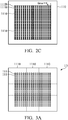
FIGs. 2A∼2C are diagrams of activating tracking sections in the liquid-crystal antenna unit 110 using time-division multiplexing in accordance with an embodiment of the disclosure. - In an embodiment, all the
microwave elements 111 in the liquid-crystal antenna unit 1110 can be divided into one ormore tracking sections 1110, as illustrated inFIG. 2B andFIG. 2C . Thecontrol unit 120 may activate or deactivate thetracking sections 1110 using time-division multiplexing. - For example, as illustrated in
FIG. 2A , at time tn, thecontrol unit 120 deactivates thetracking sections 1110, and thecontrol unit 120 determines the source orientation of the wireless signal received by themicrowave elements 111. - As illustrated in
FIG. 2B , at time tn+1, thecontrol unit 120 activates thetracking sections 1110, and themicrowave elements 111 in each of thetracking sections 1110 can be regarded as trackingmicrowave elements 111B. -
FIG. 2C shows another example of dividing themicrowave elements 111 into thetracking sections 1110. The number of trackingmicrowave elements 111B in each of thetracking sections 1110 inFIG. 2C is greater than that inFIG. 2B . That is, at time tn+1, thecontrol unit 120 may use another division methodology to activate thetracking sections 1110. - Referring to
FIG. 2B andFIG. 2C , thecontrol unit 120 may drive each of thetracking sections 1110 to alternate its directivity toward different directions, and each of thetracking sections 1110 may receive wireless signals from different angles. - For example, when a wireless apparatus steers a wireless signal from a certain orientation, the wireless signal received by each of the
tracking sections 1110 may have different signal characteristics since the directivities of thetracking sections 1110 are different from each other. Accordingly, thecontrol unit 120 may calculate the source orientation of the wireless signal transmitted by the wireless apparatus according to the characteristics of the wireless signal received by each of thetracking sections 1110. The wireless apparatus may be a mobile communication apparatus, a base station, or a communications satellite, but the disclosure is not limited thereto. - Then, the
control unit 120 may drive a portion of or all of themicrowave elements 111 in the liquid-crystal antenna unit 110, so that the beam formed by the drivenmicrowave elements 111 to direct toward the source orientation of the wireless signal. As the location of the wireless apparatus changes, the characteristics of the wireless signal received by each of thetracking sections 1110 may vary accordingly. Thus, thecontrol unit 120 may further calculate the new source orientation of the wireless signal transmitted by the wireless apparatus after movement according to the characteristics of the wireless signals received by each of thetracking sections 1110, thereby achieving the function of tracking the wireless apparatus. - In some embodiments, in the initial state, the
control unit 120 may activate a portion of or all of thetracking sections 1110, and themicrowave elements 111 in the remainingtracking sections 1110 are not activated. Responsive to the determination of the source orientation of the wireless signal by thecontrol unit 120, thecontrol unit 120 may activate all of or some selected microwave elements to form a beam to direct toward the source orientation of the wireless signal. -
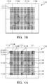
FIGs. 3A∼3B are diagrams of different divisions of the tracking sections in accordance with another embodiment of the disclosure. All of themicrowave elements 111 in the liquid-crystal antenna unit 110 can be divided into one ormore tracking sections 1110 using different ways. In an embodiment, as illustrated inFIG. 3A , thecontrol unit 120 may divide all of themicrowave elements 111 into a plurality of trackingsections 1110 that forms a 3x3 grid. - In another embodiment, as illustrated in
FIG. 3B , thecontrol unit 120 may symmetrically divide all of themicrowave elements 111 into a plurality of trackingsections 1110 relative to the center of the two-dimensional array of themicrowave elements 111. - It should be noted that the divisions of the
microwave elements 111 into one ormore tracking sections 1110 are not limited to the divisions shown inFIG. 3A andFIG. 3B . For example, the divisions of thetracking sections 1110 may be in different shapes such as a cone, a triangle, a rectangular, a polygon, a non-regular shape, or a ring shape, but the disclosure is not limited thereto. -
FIGs. 4A∼4C are diagrams of different divisions of the tracking sections in accordance with yet another embodiment of the disclosure. In yet another embodiment, as illustrated inFIG. 4A , thecontrol unit 120 may divide themicrowave elements 111 of the liquid-crystal antenna unit 110 into a plurality ofregions 1111 that forms a 3x3 grid, and themicrowave elements 111 in each of theregions 1111 are classified into a first portion and a second portion. The first portion of the microwave elements indicates the one or moretracking microwave elements 111B used as thetracking section 1110 in each of theregions 1111, and the second portions of the microwave elements indicates the remainingmicrowave elements 111A in each of theregions 1111. - That is, the
control unit 120 may select the first portion of the microwave elements 111 (e.g., trackingmicrowave elements 111B) in each of theregions 1111 as thetracking section 1110, and each of thetracking sections 1110 has a directivity for receiving wireless signals, and the directivities of thetracking sections 1110 may be different. Thecontrol unit 120 may determine the source orientation of the wireless signal according to the wireless signal received by each of thetracking sections 1110. Thecontrol unit 120 may designate themicrowave elements 111A in one or more regions to form a beam to direct toward the source orientation of the wireless signal. - Similarly, in
FIG. 4B , thecontrol unit 120 may use another symmetrical division to divide themicrowave elements 111 of the liquid-crystal antenna unit 110 into a plurality ofregions 1111. InFIG. 4A andFIG. 4B , thecontrol unit 120 may select fixed trackingmicrowave elements 111B as thetracking sections 1110, and the arrangement of the trackingmicrowave elements 111B in each of thetracking sections 1110 may be identical to each other. - As illustrated in
FIG. 4C , thecontrol unit 120 uses yet another symmetrical division to divide themicrowave elements 111 of the liquid-crystal antenna unit 110 into a plurality ofregions 1111, and the arrangement of the trackingmicrowave elements 111B in each of thetracking sections 1110 may be different. - In view of the embodiments in
FIGs. 4A∼4C , it will be appreciated that there are one or more arrangements of the trackingmicrowave elements 111B of thetracking section 1110 in each of theregions 1111. -
FIGs. 5A∼5D are diagrams of activatingtracking sections 1110 in the liquid-crystal antenna unit 110 using time-division multiplexing in accordance with an embodiment of the disclosure. In an embodiment, thecontrol unit 120 may activate thetracking section 1110 in each of theregions 1111 in the liquid-crystal antenna unit 110 using time-division multiplexing. For example, as illustrated inFIG. 5A , at time tn, thecontrol unit 120 does not activate any of thetracking sections 1110 in each of theregions 1111 in the liquid-crystal antenna unit 110. As illustrated inFIG. 5B , at time tn+1, thecontrol unit 120 activates a portion of the microwave elements 111 (e.g., trackingmicrowave elements 111B) in each of theregions 1111 in the liquid-crystal antenna unit 110 as thetracking sections 1110, and each of thetracking sections 1110 has a different directivity for receiving wireless signals. - In another embodiment, as illustrated in
FIG. 5C and FIG. 5D , thecontrol unit 120 may alternate the positions or the arrangement of thetracking sections 1110 in each of theregions 1111 in the liquid-crystal antenna unit 110 using time-division multiplexing. For example, at time tn, thecontrol unit 120 activates thetracking section 1110 in each of theregions 1111 in the liquid-crystal antenna unit 110 using the arrangement shown inFIG. 5C . At time tn+1, thecontrol unit 120 activates thetracking section 1110 in each of theregions 1111 in the liquid-crystal antenna unit 110 using the arrangement shown inFIG. 5D . However, the positions of thetracking sections 1110 inFIG. 5D are slightly different from those inFIG. 5C . -
FIGs. 6A∼6B are diagrams of the arrangement of thetracking sections 1110 in accordance with another embodiment of the disclosure. In another embodiment, thecontrol unit 120 may divide all of themicrowave elements 111 into a plurality ofregions 1111 using the arrangement shown inFIG. 4A orFIG. 4B , and themicrowave elements 111 in each of theregions 1111 can be classified into a plurality of first microwave elements 11 1B and a plurality ofsecond microwave elements 111A. Thesecond microwave elements 111A are arranged into a two-dimensional array, and thefirst microwave elements 111B are disposed around the two-dimensional array to form one ormore tracking sections 1110, as illustrated inFIG. 6A and FIG. 6B . -
FIG. 7 is a flow chart of a method of tracking a wireless apparatus using the liquid-crystal antenna apparatus 110 in accordance with an embodiment of the disclosure. - In step S710, a wireless signal is received by the
microwave elements 111. - In step S720, the source orientation of the wireless signal is determined according to the wireless signal received by the
microwave elements 111. For example, themicrowave elements 111 may receive the wireless signal using an active scan or a passive reception, wherein the passive reception can be referred to in the embodiments ofFIGs. 2∼6 , and thus the details of the passive reception will be omitted here. The details of the active scan can be found in the embodiment ofFIG. 8 . - In step S730, the direction of a beam formed by the
microwave elements 111 is controlled within a predetermined space. For example, the direction of the beam formed by the liquid-crystal antenna unit 110 can be operated within a three-dimensional space, as illustrated inFIG. 9A which is a diagram of apredetermined space 900 for operation by the liquid-crystal antenna unit 110 in accordance with an embodiment of the disclosure.FIG. 9B is a top view of the liquid-crystal antenna unit 110 in accordance with the embodiment ofFIG. 9A . The direction of the beam of the liquid-crystal antenna unit 110 can be operated within a respective range of an angle α exterior to the left side and the right side of the liquid-crystal antenna unit 110, as illustrated inFIG. 9B. FIG. 9C is a side view of the liquid-crystal antenna unit 110 in accordance with the embodiment ofFIG. 9A . The direction of the beam of the liquid-crystal antenna unit 110 can be operated within a respective range of an angle β exterior to the top side and the bottom side of the liquid-crystal antenna unit 110. The angles α and β may be the same in some embodiments, or different in other embodiments. - In step S740, the direction of the beam of the liquid-
crystal antenna unit 110 is controlled to substantially direct toward the source orientation of the wireless signal. If the wireless apparatus is moving, the source of the wireless signal may be shifted a distance from the original source location due to motion after the beam is controlled to direct toward the calculated source orientation. Since the liquid-crystal antenna unit 110 is capable of tracking the wireless apparatus, the direction of the beam form by the liquid-crystal antenna unit 110 can be repeatedly calibrated to substantially direct toward the source orientation of the wireless signal. -
FIG. 8 is a flow chart of a method for determining the source orientation of the wireless signal using an active scan in accordance with another embodiment of the disclosure. In another embodiment, in step S810, thecontrol unit 120 controls the directivity of thetracking sections 1110 in the liquid-crystal antenna unit 110 to scan within a predetermined space, wherein the above-mentioned scan is regarded as an active scan. It indicates that the directivity of thetracking sections 1110 may have an angle change at every time point such as time points from to to tn. However, the angle change is not limited to the change toward the upper direction/bottom directions, or left/right directions of the liquid-crystal antenna unit 110. At last, the directivity of thetracking sections 1110 may sweep the whole predetermined space. In addition, the division of thetracking sections 1110 can be referred to in the aforementioned embodiments. - In step S820, when the characteristics of the wireless signal received by the
tracking sections 1110 at a specific time point reaches a predetermined condition (e.g., having the relatively maximum signal strength) in comparison with that in other time points, thecontrol unit 120 may determine that the directivity of thetracking sections 1110 at the specific time point directs toward the source orientation of the wireless signal, and steer the beam of the liquid-crystal antenna unit 110 to direct toward the source orientation of the wireless signal. - The direction of the beam formed by the liquid-
crystal antenna unit 110 can be operated within a three-dimensional space. As illustrated inFIG. 9A ,FIG.9B, and FIG. 9C , the scan range of the directivity of thetracking sections 1110 of the liquid-crystal antenna unit 110 can be within thepredetermined space 900 which includes a range of angle α exterior to the lines extended from the left side or the right side of the liquid-crystal antenna unit 110, and a range of angle β exterior to the lines extended from the upper side or the bottom side of the liquid-crystal antenna unit 110. The angles α and β may be the same in some embodiments, or different in other embodiments. That is, the direction of the beam (e.g., a first direction) formed by the liquid-crystal antenna unit 110 can be alternated within thepredetermined space 900. - For example, in a first time interval (e.g., between time points t0∼tn), since the liquid-
crystal antenna unit 110 performs the active scan to detect the source orientation of the wireless signal, a larger range is used for the active scan within thepredetermined space 900. For example, the liquid-crystal antenna unit 110 may perform the active scan within the ranges of angles α and β as described above. When thecontrol unit 120 determines the source orientation of the wireless signal using the tracking sections 1110 (e.g., determining the directivity of thetracking sections 1110 at the time point tm, where 0<m<n), thecontrol unit 120 controls the liquid-crystal antenna unit 110 at the second time interval (e.g. from time point tn+1 to tn+x, where x > 1), so that the direction of the beam of the liquid-crystal antenna unit 110 may direct toward the source orientation of the wireless signal. Since the source of the wireless signal may move, thetracking sections 1110 of the liquid-crystal antenna unit 110 may scan the wireless signal with a shrunk range in the third time interval (e.g., from time point tn+x+1 to tn+x+y, where y>1). That is, the space for scanning the wireless signal is shrunk to a smaller space around the source orientation of the wireless signal, and the smaller space around the source orientation of the wireless signal is still within thepredetermined space 900. For example, the smaller space may indicate a first range that has an angle exterior to a normal of a surface of the liquid-crystal antenna unit 110. Accordingly, the speed for tracking the source orientation of the wireless signal can be improved. - In view of the above, a liquid-crystal antenna apparatus and a method for tracking a wireless signal thereof are provided. The liquid-crystal antenna apparatus and the method is capable of quickly positioning and tracking the wireless apparatus and providing a better signal quality of signal transmission with the wireless apparatus using the adjustability of the directivity of the microwave elements in the liquid-crystal antenna apparatus. In addition, a portion of the microwave elements can be used as the tracking sections, and the stress time of the microwave elements can be reduced using the time-division multiplexing, beam management, and/or alternating arrangements of the microwave elements, thereby increasing the life time of the microwave elements.
- While the disclosure has been described by way of example and in terms of the preferred embodiments, it should be understood that the disclosure is not limited to the disclosed embodiments. On the contrary, it is intended to cover various modifications and similar arrangements (as would be apparent to those skilled in the art). Therefore, the scope of the appended claims should be accorded the broadest interpretation so as to encompass all such modifications and similar arrangements.
Claims (15)
- A liquid-crystal antenna apparatus (100), comprising:a liquid-crystal antenna unit (110), configured to receive a wireless signal, wherein the liquid-crystal antenna unit (110) comprises a plurality of microwave elements (111), and each of the microwave elements (111) comprises a first electrode (131), a second electrode (132) opposite to the first electrode (131), and a liquid-crystal cell (133) disposed between the first electrode (131) and the second electrode (132); anda control unit (120), electrically connected to the liquid-crystal antenna unit (110), configured to control the liquid-crystal antenna unit (110) to form a first beam having a first direction,wherein the control unit (120) determines a source orientation of the wireless signal according to the wireless signal received by the liquid-crystal antenna unit (110), and controls the first direction of the first beam to direct toward the source orientation.
- The liquid-crystal antenna as claimed in claim 1, wherein the plurality of microwave elements are divided into a first portion and a second portion, and the plurality of microwave elements in the first portion are configured to receive the wireless signal.
- The liquid-crystal antenna as claimed in claim 2, wherein the plurality of microwave elements in the first portion are divided into a plurality of regions, and each of the regions has a directivity.
- The liquid-crystal antenna as claimed in claim 2 or 3, wherein the plurality of microwave elements in the second portion are configured to form the first beam.
- The liquid-crystal antenna as claimed in any of the claims 1 to 4, wherein the liquid-crystal antenna unit simultaneously receives the wireless signal and forms the first beam.
- The liquid-crystal antenna as claimed in any of the claims 2 to 4, wherein the plurality of microwave elements in the first portion receive the wireless signal at a time interval and forms the first beam at another time interval.
- The liquid-crystal antenna apparatus as claimed in any of the claims 2 to 6, wherein the control unit changes position or arrangement of the first portion of the microwave elements in different time intervals.
- The liquid-crystal antenna apparatus as claimed in claim 1, wherein the control unit further controls the liquid-crystal antenna unit to alternate the first direction of the first beam and determines the source orientation of the wireless signal according to the wireless signal received by the liquid-crystal antenna unit in a first time interval,
wherein the control unit further controls the liquid-crystal antenna unit to direct the first direction of the first beam toward the determined source orientation in a second time interval later than the first time interval. - The liquid-crystal antenna apparatus as claimed in claim 8, wherein the first direction of the first beam is changed within a first range that has an angle exterior to a normal of a surface of the liquid-crystal antenna unit.
- The liquid-crystal antenna apparatus as claimed in claim 9, wherein the first direction of the first beam is changed within a second range inside the first range in a third time interval later than the second time interval.
- A method for tracking a wireless apparatus using a liquid-crystal antenna apparatus (100), wherein the liquid-crystal antenna apparatus (100) comprises a liquid-crystal antenna unit (110) having a plurality of microwave elements (111), the method comprising:receiving a wireless signal via the liquid-crystal antenna unit (110);determining a source orientation of the wireless signal according to the wireless signal received by the microwave elements (111); andcontrolling a first direction of a first beam formed by the liquid-crystal antenna unit (110) to direct toward the source orientation of the wireless signal.
- The method as claimed in claim 11, wherein the microwave elements are divided into a first portion and a second portion, and the microwave elements in the first portion are configured to receive the wireless signal.
- The method as claimed in claim 12, wherein the first portion of the microwave elements is divided into a plurality of regions, and each of the regions has a directivity.
- The method as claimed in claim 12 or 13, wherein the second portion of the microwave elements is configured to form the first beam.
- The method as claimed in any of the claims 12 to 14, further comprising:
controlling the first portion of the microwave elements to receive the wireless signal at a first time interval and form the first beam at a second time interval later than the first time interval.
Applications Claiming Priority (2)
| Application Number | Priority Date | Filing Date | Title |
|---|---|---|---|
| US201762527192P | 2017-06-30 | 2017-06-30 | |
| CN201810380006.4A CN109216887A (en) | 2017-06-30 | 2018-04-25 | Liquid crystal antenna device |
Publications (2)
| Publication Number | Publication Date |
|---|---|
| EP3422477A1 true EP3422477A1 (en) | 2019-01-02 |
| EP3422477B1 EP3422477B1 (en) | 2021-08-11 |
Family
ID=62816345
Family Applications (1)
| Application Number | Title | Priority Date | Filing Date |
|---|---|---|---|
| EP18180350.3A Active EP3422477B1 (en) | 2017-06-30 | 2018-06-28 | Liquid-crystal antenna apparatus and method for tracking wireless apparatus using the same |
Country Status (2)
| Country | Link |
|---|---|
| US (1) | US10811769B2 (en) |
| EP (1) | EP3422477B1 (en) |
Cited By (2)
| Publication number | Priority date | Publication date | Assignee | Title |
|---|---|---|---|---|
| WO2022032889A1 (en) * | 2020-08-13 | 2022-02-17 | 上海天马微电子有限公司 | Liquid crystal antenna |
| EP4044370B1 (en) * | 2019-11-18 | 2025-10-22 | Huawei Technologies Co., Ltd. | Beam direction adjustment method and apparatus, and antenna system |
Families Citing this family (2)
| Publication number | Priority date | Publication date | Assignee | Title |
|---|---|---|---|---|
| US10581160B2 (en) | 2016-12-16 | 2020-03-03 | Gopro, Inc. | Rotational wireless communication system |
| WO2023231702A1 (en) * | 2022-05-31 | 2023-12-07 | 京东方科技集团股份有限公司 | Liquid crystal antenna array and electronic device |
Citations (1)
| Publication number | Priority date | Publication date | Assignee | Title |
|---|---|---|---|---|
| WO2015126550A1 (en) * | 2014-02-19 | 2015-08-27 | Kymeta Corporation | Dynamic polarization and coupling control for a steerable cylindrically fed holographic antenna |
Family Cites Families (4)
| Publication number | Priority date | Publication date | Assignee | Title |
|---|---|---|---|---|
| CN103198284B (en) | 2012-04-09 | 2016-03-30 | 公安部第三研究所 | A kind of active RFID locating card reader based on microstrip array directional antenna battle array location |
| CN103297104B (en) | 2013-06-09 | 2015-10-28 | 清华大学 | Antenna array configuration method and aerial array |
| US10446939B2 (en) * | 2017-01-16 | 2019-10-15 | Innolux Corporation | Liquid-crystal antenna apparatus and electronic communication device |
| JP2019125908A (en) * | 2018-01-16 | 2019-07-25 | シャープ株式会社 | Liquid crystal cell, and sweep antenna |
-
2018
- 2018-06-05 US US16/000,242 patent/US10811769B2/en active Active
- 2018-06-28 EP EP18180350.3A patent/EP3422477B1/en active Active
Patent Citations (1)
| Publication number | Priority date | Publication date | Assignee | Title |
|---|---|---|---|---|
| WO2015126550A1 (en) * | 2014-02-19 | 2015-08-27 | Kymeta Corporation | Dynamic polarization and coupling control for a steerable cylindrically fed holographic antenna |
Non-Patent Citations (2)
| Title |
|---|
| HU W ET AL: "Liquid-crystal-based reflectarray antenna with electronically switchable monopulse patterns", ELECTRONICS LET, IEE STEVENAGE, GB, vol. 43, no. 14, 5 July 2007 (2007-07-05), pages 744 - 745, XP006029170, ISSN: 0013-5194, DOI: 10.1049/EL:20071098 * |
| PEREZ-PALOMINO GERARDO ET AL: "Design and Demonstration of an Electronically Scanned Reflectarray Antenna at 100 GHz Using Multiresonant Cells Based on Liquid Crystals", IEEE TRANSACTIONS ON ANTENNAS AND PROPAGATION, IEEE SERVICE CENTER, PISCATAWAY, NJ, US, vol. 63, no. 8, 1 August 2015 (2015-08-01), pages 3722 - 3727, XP011664788, ISSN: 0018-926X, [retrieved on 20150731], DOI: 10.1109/TAP.2015.2434421 * |
Cited By (3)
| Publication number | Priority date | Publication date | Assignee | Title |
|---|---|---|---|---|
| EP4044370B1 (en) * | 2019-11-18 | 2025-10-22 | Huawei Technologies Co., Ltd. | Beam direction adjustment method and apparatus, and antenna system |
| WO2022032889A1 (en) * | 2020-08-13 | 2022-02-17 | 上海天马微电子有限公司 | Liquid crystal antenna |
| US12160051B2 (en) | 2020-08-13 | 2024-12-03 | Shanghai Tianma Micro-electronics Co., Ltd. | Liquid crystal antenna |
Also Published As
| Publication number | Publication date |
|---|---|
| US10811769B2 (en) | 2020-10-20 |
| EP3422477B1 (en) | 2021-08-11 |
| US20190006752A1 (en) | 2019-01-03 |
Similar Documents
| Publication | Publication Date | Title |
|---|---|---|
| US12199347B2 (en) | Null steering antenna techniques for advanced communication systems | |
| US11239572B2 (en) | Beam-steering reconfigurable antenna arrays | |
| US10811769B2 (en) | Liquid-crystal antenna apparatus and method for tracking wireless apparatus using the same | |
| US9147935B2 (en) | Maintenance of mobile device RF beam | |
| KR20210154182A (en) | Low Complexity Beam Steering of Array Aperture | |
| US8963774B1 (en) | Adaptive nulling for parasitic array antennas | |
| EP3231037B1 (en) | High coverage antenna array and method using grating lobe layers | |
| US8648768B2 (en) | Conical switched beam antenna method and apparatus | |
| KR101803208B1 (en) | Beamfoaming anttena using single radiator multi port | |
| JP4724862B2 (en) | Array antenna | |
| CN105186137A (en) | Multi-resonant structure based single-feed anti-multipath adaptive antenna | |
| JP3822607B2 (en) | Array antenna | |
| CN109216887A (en) | Liquid crystal antenna device | |
| KR101271356B1 (en) | Circular polarized antenna system | |
| EP4358296B1 (en) | Antenna and antenna system | |
| KR102209380B1 (en) | Rf lens apparatus for improving directivity of antenna array and transmitting-receiving antenna system including the same | |
| EP4178039B1 (en) | Electronically steered beam antenna of espar type | |
| CN103943961A (en) | Electric scanning antenna based on space phase shift surface | |
| KR102003935B1 (en) | Apparatus and method for array antenna beamforming | |
| EP3130039B1 (en) | A wireless communication system node arranged for determining pointing deviation | |
| JP2008053950A (en) | Array antenna and base station | |
| JP4342542B2 (en) | Array antenna and base station | |
| JP2007049223A (en) | Directional variable antenna | |
| JP2019041256A (en) | Antenna and radio wave direction changing method | |
| Hara et al. | A calculation technique of multi-beam directions for emitter detection |
Legal Events
| Date | Code | Title | Description |
|---|---|---|---|
| PUAI | Public reference made under article 153(3) epc to a published international application that has entered the european phase |
Free format text: ORIGINAL CODE: 0009012 |
|
| STAA | Information on the status of an ep patent application or granted ep patent |
Free format text: STATUS: THE APPLICATION HAS BEEN PUBLISHED |
|
| AK | Designated contracting states |
Kind code of ref document: A1 Designated state(s): AL AT BE BG CH CY CZ DE DK EE ES FI FR GB GR HR HU IE IS IT LI LT LU LV MC MK MT NL NO PL PT RO RS SE SI SK SM TR |
|
| AX | Request for extension of the european patent |
Extension state: BA ME |
|
| STAA | Information on the status of an ep patent application or granted ep patent |
Free format text: STATUS: REQUEST FOR EXAMINATION WAS MADE |
|
| 17P | Request for examination filed |
Effective date: 20190313 |
|
| RBV | Designated contracting states (corrected) |
Designated state(s): AL AT BE BG CH CY CZ DE DK EE ES FI FR GB GR HR HU IE IS IT LI LT LU LV MC MK MT NL NO PL PT RO RS SE SI SK SM TR |
|
| RIC1 | Information provided on ipc code assigned before grant |
Ipc: G01S 3/38 20060101ALI20201215BHEP Ipc: H01Q 3/24 20060101AFI20201215BHEP |
|
| GRAP | Despatch of communication of intention to grant a patent |
Free format text: ORIGINAL CODE: EPIDOSNIGR1 |
|
| STAA | Information on the status of an ep patent application or granted ep patent |
Free format text: STATUS: GRANT OF PATENT IS INTENDED |
|
| INTG | Intention to grant announced |
Effective date: 20210127 |
|
| RAP1 | Party data changed (applicant data changed or rights of an application transferred) |
Owner name: INNOLUX CORPORATION |
|
| GRAS | Grant fee paid |
Free format text: ORIGINAL CODE: EPIDOSNIGR3 |
|
| GRAA | (expected) grant |
Free format text: ORIGINAL CODE: 0009210 |
|
| STAA | Information on the status of an ep patent application or granted ep patent |
Free format text: STATUS: THE PATENT HAS BEEN GRANTED |
|
| AK | Designated contracting states |
Kind code of ref document: B1 Designated state(s): AL AT BE BG CH CY CZ DE DK EE ES FI FR GB GR HR HU IE IS IT LI LT LU LV MC MK MT NL NO PL PT RO RS SE SI SK SM TR |
|
| REG | Reference to a national code |
Ref country code: CH Ref legal event code: EP |
|
| REG | Reference to a national code |
Ref country code: DE Ref legal event code: R096 Ref document number: 602018021511 Country of ref document: DE |
|
| REG | Reference to a national code |
Ref country code: IE Ref legal event code: FG4D Ref country code: AT Ref legal event code: REF Ref document number: 1420341 Country of ref document: AT Kind code of ref document: T Effective date: 20210915 |
|
| REG | Reference to a national code |
Ref country code: LT Ref legal event code: MG9D |
|
| REG | Reference to a national code |
Ref country code: NL Ref legal event code: MP Effective date: 20210811 |
|
| REG | Reference to a national code |
Ref country code: AT Ref legal event code: MK05 Ref document number: 1420341 Country of ref document: AT Kind code of ref document: T Effective date: 20210811 |
|
| PG25 | Lapsed in a contracting state [announced via postgrant information from national office to epo] |
Ref country code: LT Free format text: LAPSE BECAUSE OF FAILURE TO SUBMIT A TRANSLATION OF THE DESCRIPTION OR TO PAY THE FEE WITHIN THE PRESCRIBED TIME-LIMIT Effective date: 20210811 Ref country code: BG Free format text: LAPSE BECAUSE OF FAILURE TO SUBMIT A TRANSLATION OF THE DESCRIPTION OR TO PAY THE FEE WITHIN THE PRESCRIBED TIME-LIMIT Effective date: 20211111 Ref country code: AT Free format text: LAPSE BECAUSE OF FAILURE TO SUBMIT A TRANSLATION OF THE DESCRIPTION OR TO PAY THE FEE WITHIN THE PRESCRIBED TIME-LIMIT Effective date: 20210811 Ref country code: PT Free format text: LAPSE BECAUSE OF FAILURE TO SUBMIT A TRANSLATION OF THE DESCRIPTION OR TO PAY THE FEE WITHIN THE PRESCRIBED TIME-LIMIT Effective date: 20211213 Ref country code: NO Free format text: LAPSE BECAUSE OF FAILURE TO SUBMIT A TRANSLATION OF THE DESCRIPTION OR TO PAY THE FEE WITHIN THE PRESCRIBED TIME-LIMIT Effective date: 20211111 Ref country code: HR Free format text: LAPSE BECAUSE OF FAILURE TO SUBMIT A TRANSLATION OF THE DESCRIPTION OR TO PAY THE FEE WITHIN THE PRESCRIBED TIME-LIMIT Effective date: 20210811 Ref country code: ES Free format text: LAPSE BECAUSE OF FAILURE TO SUBMIT A TRANSLATION OF THE DESCRIPTION OR TO PAY THE FEE WITHIN THE PRESCRIBED TIME-LIMIT Effective date: 20210811 Ref country code: FI Free format text: LAPSE BECAUSE OF FAILURE TO SUBMIT A TRANSLATION OF THE DESCRIPTION OR TO PAY THE FEE WITHIN THE PRESCRIBED TIME-LIMIT Effective date: 20210811 Ref country code: RS Free format text: LAPSE BECAUSE OF FAILURE TO SUBMIT A TRANSLATION OF THE DESCRIPTION OR TO PAY THE FEE WITHIN THE PRESCRIBED TIME-LIMIT Effective date: 20210811 Ref country code: SE Free format text: LAPSE BECAUSE OF FAILURE TO SUBMIT A TRANSLATION OF THE DESCRIPTION OR TO PAY THE FEE WITHIN THE PRESCRIBED TIME-LIMIT Effective date: 20210811 |
|
| PG25 | Lapsed in a contracting state [announced via postgrant information from national office to epo] |
Ref country code: PL Free format text: LAPSE BECAUSE OF FAILURE TO SUBMIT A TRANSLATION OF THE DESCRIPTION OR TO PAY THE FEE WITHIN THE PRESCRIBED TIME-LIMIT Effective date: 20210811 Ref country code: LV Free format text: LAPSE BECAUSE OF FAILURE TO SUBMIT A TRANSLATION OF THE DESCRIPTION OR TO PAY THE FEE WITHIN THE PRESCRIBED TIME-LIMIT Effective date: 20210811 Ref country code: GR Free format text: LAPSE BECAUSE OF FAILURE TO SUBMIT A TRANSLATION OF THE DESCRIPTION OR TO PAY THE FEE WITHIN THE PRESCRIBED TIME-LIMIT Effective date: 20211112 |
|
| PG25 | Lapsed in a contracting state [announced via postgrant information from national office to epo] |
Ref country code: NL Free format text: LAPSE BECAUSE OF FAILURE TO SUBMIT A TRANSLATION OF THE DESCRIPTION OR TO PAY THE FEE WITHIN THE PRESCRIBED TIME-LIMIT Effective date: 20210811 |
|
| PG25 | Lapsed in a contracting state [announced via postgrant information from national office to epo] |
Ref country code: DK Free format text: LAPSE BECAUSE OF FAILURE TO SUBMIT A TRANSLATION OF THE DESCRIPTION OR TO PAY THE FEE WITHIN THE PRESCRIBED TIME-LIMIT Effective date: 20210811 |
|
| REG | Reference to a national code |
Ref country code: DE Ref legal event code: R097 Ref document number: 602018021511 Country of ref document: DE |
|
| PG25 | Lapsed in a contracting state [announced via postgrant information from national office to epo] |
Ref country code: SM Free format text: LAPSE BECAUSE OF FAILURE TO SUBMIT A TRANSLATION OF THE DESCRIPTION OR TO PAY THE FEE WITHIN THE PRESCRIBED TIME-LIMIT Effective date: 20210811 Ref country code: SK Free format text: LAPSE BECAUSE OF FAILURE TO SUBMIT A TRANSLATION OF THE DESCRIPTION OR TO PAY THE FEE WITHIN THE PRESCRIBED TIME-LIMIT Effective date: 20210811 Ref country code: RO Free format text: LAPSE BECAUSE OF FAILURE TO SUBMIT A TRANSLATION OF THE DESCRIPTION OR TO PAY THE FEE WITHIN THE PRESCRIBED TIME-LIMIT Effective date: 20210811 Ref country code: EE Free format text: LAPSE BECAUSE OF FAILURE TO SUBMIT A TRANSLATION OF THE DESCRIPTION OR TO PAY THE FEE WITHIN THE PRESCRIBED TIME-LIMIT Effective date: 20210811 Ref country code: CZ Free format text: LAPSE BECAUSE OF FAILURE TO SUBMIT A TRANSLATION OF THE DESCRIPTION OR TO PAY THE FEE WITHIN THE PRESCRIBED TIME-LIMIT Effective date: 20210811 Ref country code: AL Free format text: LAPSE BECAUSE OF FAILURE TO SUBMIT A TRANSLATION OF THE DESCRIPTION OR TO PAY THE FEE WITHIN THE PRESCRIBED TIME-LIMIT Effective date: 20210811 |
|
| PLBE | No opposition filed within time limit |
Free format text: ORIGINAL CODE: 0009261 |
|
| STAA | Information on the status of an ep patent application or granted ep patent |
Free format text: STATUS: NO OPPOSITION FILED WITHIN TIME LIMIT |
|
| 26N | No opposition filed |
Effective date: 20220512 |
|
| PG25 | Lapsed in a contracting state [announced via postgrant information from national office to epo] |
Ref country code: IT Free format text: LAPSE BECAUSE OF FAILURE TO SUBMIT A TRANSLATION OF THE DESCRIPTION OR TO PAY THE FEE WITHIN THE PRESCRIBED TIME-LIMIT Effective date: 20210811 |
|
| PG25 | Lapsed in a contracting state [announced via postgrant information from national office to epo] |
Ref country code: SI Free format text: LAPSE BECAUSE OF FAILURE TO SUBMIT A TRANSLATION OF THE DESCRIPTION OR TO PAY THE FEE WITHIN THE PRESCRIBED TIME-LIMIT Effective date: 20210811 |
|
| PG25 | Lapsed in a contracting state [announced via postgrant information from national office to epo] |
Ref country code: MC Free format text: LAPSE BECAUSE OF FAILURE TO SUBMIT A TRANSLATION OF THE DESCRIPTION OR TO PAY THE FEE WITHIN THE PRESCRIBED TIME-LIMIT Effective date: 20210811 |
|
| REG | Reference to a national code |
Ref country code: CH Ref legal event code: PL |
|
| REG | Reference to a national code |
Ref country code: BE Ref legal event code: MM Effective date: 20220630 |
|
| PG25 | Lapsed in a contracting state [announced via postgrant information from national office to epo] |
Ref country code: LU Free format text: LAPSE BECAUSE OF NON-PAYMENT OF DUE FEES Effective date: 20220628 Ref country code: LI Free format text: LAPSE BECAUSE OF NON-PAYMENT OF DUE FEES Effective date: 20220630 Ref country code: IE Free format text: LAPSE BECAUSE OF NON-PAYMENT OF DUE FEES Effective date: 20220628 Ref country code: CH Free format text: LAPSE BECAUSE OF NON-PAYMENT OF DUE FEES Effective date: 20220630 |
|
| PG25 | Lapsed in a contracting state [announced via postgrant information from national office to epo] |
Ref country code: BE Free format text: LAPSE BECAUSE OF NON-PAYMENT OF DUE FEES Effective date: 20220630 |
|
| PG25 | Lapsed in a contracting state [announced via postgrant information from national office to epo] |
Ref country code: HU Free format text: LAPSE BECAUSE OF FAILURE TO SUBMIT A TRANSLATION OF THE DESCRIPTION OR TO PAY THE FEE WITHIN THE PRESCRIBED TIME-LIMIT; INVALID AB INITIO Effective date: 20180628 |
|
| PG25 | Lapsed in a contracting state [announced via postgrant information from national office to epo] |
Ref country code: MK Free format text: LAPSE BECAUSE OF FAILURE TO SUBMIT A TRANSLATION OF THE DESCRIPTION OR TO PAY THE FEE WITHIN THE PRESCRIBED TIME-LIMIT Effective date: 20210811 Ref country code: CY Free format text: LAPSE BECAUSE OF FAILURE TO SUBMIT A TRANSLATION OF THE DESCRIPTION OR TO PAY THE FEE WITHIN THE PRESCRIBED TIME-LIMIT Effective date: 20210811 |
|
| PG25 | Lapsed in a contracting state [announced via postgrant information from national office to epo] |
Ref country code: TR Free format text: LAPSE BECAUSE OF FAILURE TO SUBMIT A TRANSLATION OF THE DESCRIPTION OR TO PAY THE FEE WITHIN THE PRESCRIBED TIME-LIMIT Effective date: 20210811 |
|
| PG25 | Lapsed in a contracting state [announced via postgrant information from national office to epo] |
Ref country code: MT Free format text: LAPSE BECAUSE OF FAILURE TO SUBMIT A TRANSLATION OF THE DESCRIPTION OR TO PAY THE FEE WITHIN THE PRESCRIBED TIME-LIMIT Effective date: 20210811 |
|
| PGFP | Annual fee paid to national office [announced via postgrant information from national office to epo] |
Ref country code: DE Payment date: 20250528 Year of fee payment: 8 |
|
| PGFP | Annual fee paid to national office [announced via postgrant information from national office to epo] |
Ref country code: GB Payment date: 20250522 Year of fee payment: 8 |
|
| PGFP | Annual fee paid to national office [announced via postgrant information from national office to epo] |
Ref country code: FR Payment date: 20250523 Year of fee payment: 8 |