EP3422390A1 - Method for producing ni-based intermetallic contact on inxga1-xas - Google Patents
Method for producing ni-based intermetallic contact on inxga1-xas Download PDFInfo
- Publication number
- EP3422390A1 EP3422390A1 EP18180973.2A EP18180973A EP3422390A1 EP 3422390 A1 EP3422390 A1 EP 3422390A1 EP 18180973 A EP18180973 A EP 18180973A EP 3422390 A1 EP3422390 A1 EP 3422390A1
- Authority
- EP
- European Patent Office
- Prior art keywords
- temperature
- annealing
- intermetallic
- texture
- thickness
- Prior art date
- Legal status (The legal status is an assumption and is not a legal conclusion. Google has not performed a legal analysis and makes no representation as to the accuracy of the status listed.)
- Granted
Links
- 238000004519 manufacturing process Methods 0.000 title claims abstract description 28
- 238000000137 annealing Methods 0.000 claims abstract description 90
- 229910000765 intermetallic Inorganic materials 0.000 claims abstract description 38
- 239000000758 substrate Substances 0.000 claims abstract description 31
- 238000000034 method Methods 0.000 claims abstract description 24
- 230000006911 nucleation Effects 0.000 claims abstract description 19
- 238000010899 nucleation Methods 0.000 claims abstract description 19
- 239000000463 material Substances 0.000 claims abstract description 12
- 150000001875 compounds Chemical class 0.000 claims abstract description 8
- 229910000530 Gallium indium arsenide Inorganic materials 0.000 claims description 26
- 239000010410 layer Substances 0.000 claims description 22
- 238000000151 deposition Methods 0.000 claims description 9
- 238000006243 chemical reaction Methods 0.000 claims description 8
- 238000005259 measurement Methods 0.000 claims description 7
- 230000008021 deposition Effects 0.000 claims description 6
- 239000007787 solid Substances 0.000 claims description 6
- 239000000203 mixture Substances 0.000 claims description 4
- 238000011161 development Methods 0.000 claims description 3
- 238000000572 ellipsometry Methods 0.000 claims description 3
- 239000011241 protective layer Substances 0.000 claims description 3
- 230000001419 dependent effect Effects 0.000 claims 1
- PXHVJJICTQNCMI-UHFFFAOYSA-N nickel Substances [Ni] PXHVJJICTQNCMI-UHFFFAOYSA-N 0.000 description 115
- 239000012071 phase Substances 0.000 description 29
- APFVFJFRJDLVQX-UHFFFAOYSA-N indium atom Chemical compound [In] APFVFJFRJDLVQX-UHFFFAOYSA-N 0.000 description 22
- 229910052738 indium Inorganic materials 0.000 description 17
- 230000015572 biosynthetic process Effects 0.000 description 14
- 229910001218 Gallium arsenide Inorganic materials 0.000 description 8
- 239000002184 metal Substances 0.000 description 8
- 229910052751 metal Inorganic materials 0.000 description 8
- 229910052759 nickel Inorganic materials 0.000 description 8
- 239000004065 semiconductor Substances 0.000 description 6
- 238000000560 X-ray reflectometry Methods 0.000 description 4
- 230000002349 favourable effect Effects 0.000 description 4
- 238000001465 metallisation Methods 0.000 description 4
- 238000004151 rapid thermal annealing Methods 0.000 description 4
- 238000004140 cleaning Methods 0.000 description 3
- 238000009792 diffusion process Methods 0.000 description 3
- 238000003746 solid phase reaction Methods 0.000 description 3
- 238000010671 solid-state reaction Methods 0.000 description 3
- 230000004888 barrier function Effects 0.000 description 2
- 238000004320 controlled atmosphere Methods 0.000 description 2
- RPQDHPTXJYYUPQ-UHFFFAOYSA-N indium arsenide Chemical compound [In]#[As] RPQDHPTXJYYUPQ-UHFFFAOYSA-N 0.000 description 2
- 240000000966 Allium tricoccum Species 0.000 description 1
- 229910005191 Ga 2 O 3 Inorganic materials 0.000 description 1
- -1 GaAs compound Chemical class 0.000 description 1
- 229910000673 Indium arsenide Inorganic materials 0.000 description 1
- ZSBXGIUJOOQZMP-JLNYLFASSA-N Matrine Chemical compound C1CC[C@H]2CN3C(=O)CCC[C@@H]3[C@@H]3[C@H]2N1CCC3 ZSBXGIUJOOQZMP-JLNYLFASSA-N 0.000 description 1
- XUIMIQQOPSSXEZ-UHFFFAOYSA-N Silicon Chemical compound [Si] XUIMIQQOPSSXEZ-UHFFFAOYSA-N 0.000 description 1
- 241000897276 Termes Species 0.000 description 1
- ATJFFYVFTNAWJD-UHFFFAOYSA-N Tin Chemical compound [Sn] ATJFFYVFTNAWJD-UHFFFAOYSA-N 0.000 description 1
- 238000004458 analytical method Methods 0.000 description 1
- 238000012512 characterization method Methods 0.000 description 1
- 239000011247 coating layer Substances 0.000 description 1
- 238000001816 cooling Methods 0.000 description 1
- 230000007547 defect Effects 0.000 description 1
- 238000005516 engineering process Methods 0.000 description 1
- 238000002474 experimental method Methods 0.000 description 1
- 229910052733 gallium Inorganic materials 0.000 description 1
- 238000011065 in-situ storage Methods 0.000 description 1
- 239000007791 liquid phase Substances 0.000 description 1
- 238000012423 maintenance Methods 0.000 description 1
- 229910001092 metal group alloy Inorganic materials 0.000 description 1
- 238000000386 microscopy Methods 0.000 description 1
- 230000000877 morphologic effect Effects 0.000 description 1
- 230000003647 oxidation Effects 0.000 description 1
- 238000007254 oxidation reaction Methods 0.000 description 1
- 238000000819 phase cycle Methods 0.000 description 1
- 238000005086 pumping Methods 0.000 description 1
- 229910052710 silicon Inorganic materials 0.000 description 1
- 239000010703 silicon Substances 0.000 description 1
- 230000036962 time dependent Effects 0.000 description 1
Images


Classifications
-
- H—ELECTRICITY
- H01—ELECTRIC ELEMENTS
- H01L—SEMICONDUCTOR DEVICES NOT COVERED BY CLASS H10
- H01L21/00—Processes or apparatus adapted for the manufacture or treatment of semiconductor or solid state devices or of parts thereof
- H01L21/02—Manufacture or treatment of semiconductor devices or of parts thereof
- H01L21/04—Manufacture or treatment of semiconductor devices or of parts thereof the devices having potential barriers, e.g. a PN junction, depletion layer or carrier concentration layer
- H01L21/18—Manufacture or treatment of semiconductor devices or of parts thereof the devices having potential barriers, e.g. a PN junction, depletion layer or carrier concentration layer the devices having semiconductor bodies comprising elements of Group IV of the Periodic Table or AIIIBV compounds with or without impurities, e.g. doping materials
- H01L21/28—Manufacture of electrodes on semiconductor bodies using processes or apparatus not provided for in groups H01L21/20 - H01L21/268
- H01L21/283—Deposition of conductive or insulating materials for electrodes conducting electric current
- H01L21/285—Deposition of conductive or insulating materials for electrodes conducting electric current from a gas or vapour, e.g. condensation
- H01L21/28506—Deposition of conductive or insulating materials for electrodes conducting electric current from a gas or vapour, e.g. condensation of conductive layers
- H01L21/28575—Deposition of conductive or insulating materials for electrodes conducting electric current from a gas or vapour, e.g. condensation of conductive layers on semiconductor bodies comprising AIIIBV compounds
-
- H—ELECTRICITY
- H01—ELECTRIC ELEMENTS
- H01L—SEMICONDUCTOR DEVICES NOT COVERED BY CLASS H10
- H01L29/00—Semiconductor devices specially adapted for rectifying, amplifying, oscillating or switching and having potential barriers; Capacitors or resistors having potential barriers, e.g. a PN-junction depletion layer or carrier concentration layer; Details of semiconductor bodies or of electrodes thereof ; Multistep manufacturing processes therefor
- H01L29/40—Electrodes ; Multistep manufacturing processes therefor
- H01L29/401—Multistep manufacturing processes
-
- H—ELECTRICITY
- H01—ELECTRIC ELEMENTS
- H01L—SEMICONDUCTOR DEVICES NOT COVERED BY CLASS H10
- H01L29/00—Semiconductor devices specially adapted for rectifying, amplifying, oscillating or switching and having potential barriers; Capacitors or resistors having potential barriers, e.g. a PN-junction depletion layer or carrier concentration layer; Details of semiconductor bodies or of electrodes thereof ; Multistep manufacturing processes therefor
- H01L29/40—Electrodes ; Multistep manufacturing processes therefor
- H01L29/41—Electrodes ; Multistep manufacturing processes therefor characterised by their shape, relative sizes or dispositions
- H01L29/417—Electrodes ; Multistep manufacturing processes therefor characterised by their shape, relative sizes or dispositions carrying the current to be rectified, amplified or switched
- H01L29/41725—Source or drain electrodes for field effect devices
-
- H—ELECTRICITY
- H01—ELECTRIC ELEMENTS
- H01L—SEMICONDUCTOR DEVICES NOT COVERED BY CLASS H10
- H01L29/00—Semiconductor devices specially adapted for rectifying, amplifying, oscillating or switching and having potential barriers; Capacitors or resistors having potential barriers, e.g. a PN-junction depletion layer or carrier concentration layer; Details of semiconductor bodies or of electrodes thereof ; Multistep manufacturing processes therefor
- H01L29/40—Electrodes ; Multistep manufacturing processes therefor
- H01L29/43—Electrodes ; Multistep manufacturing processes therefor characterised by the materials of which they are formed
- H01L29/45—Ohmic electrodes
- H01L29/452—Ohmic electrodes on AIII-BV compounds
Definitions
- the field of the invention is that of the components in materials III-V and more precisely that of the components In x Ga 1-x As with 0 ⁇ x ⁇ 1, comprising the realization of intermetallic contacts.
- the figure 1 illustrates an example of a transistor comprising an In x Ga 1-x As channel highlighting the source, the gate and the drain, requiring the resumption of contacts.
- the figure 2 illustrates another type of configuration for photonic applications also requiring the resumption of contacts and wherein the present invention may be of particular interest.
- the contacts on In x Ga 1-x As with 0 ⁇ x ⁇ 1 compatible with Si-CMOS technology are generally made by reaction in the solid state between a metal (Ni) or a metal alloy Ni y M 1 -y and the semiconductor (InGaAs) as described in the publication of SH Kim et al., MEI 2010, 26.6 .
- the present invention relates to an optimized intermetallic contact manufacturing method.
- the advantage of the present invention lies in the fact of producing a process for obtaining an intermetallic compound which makes it possible to remain below the nucleation barrier of the unfavorable texture until all the Ni has been consumed.
- the present invention provides a solution for reproducibly mastering the morphology of the contacts through the control of texture and phase and thus to promote a lower resistivity.
- the present invention relates to a method allowing by a thermal annealing operation calibrated according to the deposited nickel thickness, to form only one type of desired first texture while avoiding forming a second undesirable texture as it will be explained and developed in the detailed description of this application.
- the rate of rise in temperature is determined lower than a maximum speed V max , said maximum speed depending on the kinetics of the texture that is formed.
- the mole fraction x of the substrate is between 0.25 and 0.80.
- the method comprises a first annealing at a first temperature during a first duration to form a first intermetallic compound of first texture and having a first phase and a second annealing at a temperature higher than said first temperature for forming a second intermetallic compound of first texture and having a second phase.
- the Ni-InGaAs intermetallic compound may typically be a Ni 2 InGaAs compound or a Ni 3 InGaAs compound.
- the process comprises an annealing carried out at a temperature of between 200 ° C. and 320 ° C., to form the first texture A, with a preference for the range 240 ° C. and 290 ° C. for a time dependent period. of the deposited Ni thickness, to form an intermetallic compound of Ni 3 InGaAs.
- the annealing time can vary between a few minutes and a few tens of minutes.
- said annealing carried out at a temperature of between 200 ° C. and 320 ° C., with a preference for the range 240 ° C. and 290 ° C. is followed by an annealing carried out at a temperature of between 250 ° C. and 250 ° C. ° C and 550 ° C to change the resistivity of said formed intermetallic contact.
- said annealing carried out at a temperature of between 200 ° C. and 320 ° C., with a preference for the range 240 ° C. and 290 ° C. is followed by annealing carried out at a temperature of between 300 ° C. ° C and 500 ° C to consolidate the Ni 3 InGaAs phase (in the low range) or form the Ni 2 InGaAs phase (in the high range).
- Ni 3 InGaAs and Ni 2 InGaAs phases have the same structure with compositions that vary according to the occupancy rate of the interstitial sites, the Ni 2 InGaAs phase being the most stable phase at high temperature (350.degree. 500 ° C).
- the charts are produced by measuring the thicknesses of intermetallic compound formed as a function of time.
- the thickness measurements are carried out by X-ray reflectivity.
- the thickness measurements are made by ellipsometry.
- the method comprises depositing a protective layer on the surface of the localized deposit of Ni, prior to (the) operation (s) of annealing.
- the invention also relates to the intermetallic contact obtained according to the method of the invention.
- the invention further relates to a method for manufacturing a transistor comprising the intermetallic contact manufacturing method of the invention.
- the invention also relates to a method of manufacturing a photonic component comprising the intermetallic contact manufacturing method of the invention.
- the plans ( 10 1 0 ) of the intermetallic are parallel to the surface (when the latter is oriented in the planes (100)) of the layer or substrate of In x Ga 1-x As while for the texture B are the planes ( 0001 ) which are parallel to the planes (111) of said surface.
- the Applicant has carried out experiments making it possible to demonstrate that the texture of the intermetallic compound can be controlled by the heat budget or the metal thickness (if it is necessary to fix the thermal budget) implemented during the reaction to the reaction.
- This temperature is between 200 ° C and 320 ° C, with a preference for the range 240 ° C and 290 ° C depending on the content of In in In x Ga 1-x As.
- the Applicant has demonstrated the influence of the annealing operation on the formation of the desired texture, without forming the undesirable texture, and this by controlling the rate of rise in temperature to reach the desired annealing temperature called final temperature of annealing, and the maintenance of this temperature during a tray and this depending on the thickness of nickel.
- the temperature range of lower contact resistance is between 300 ° C and 350 ° C.
- One overall method is to measure the thickness of formed intermetallic compound (or consumed Ni) as a function of time for different annealing temperatures. This measurement of thickness can be carried out by different methods of characterization: by an X-ray reflectivity analysis (commonly called XRR, for X-Ray Reflectivity), ellipsometry, microscopy, etc ... or any methods to extract the thickness of the intermetallic compound and that of Ni.
- the Applicant has carried out various studies to determine the parameters making it possible to optimize the annealing operation while forming only the first texture A, avoiding forming the second texture B.
- FIGS. 5a-5c , 6a-6c , 7a-7c illustrate the appearance of the second texture beyond the nucleation temperature of the second texture, as a function of the annealing speed and as a function of the thickness of Ni deposited.
- the Figures 8a-8c illustrate in a generic way the preceding figures, by materializing by zones shaded, the zones to exclude (zone where the texture B is likely to form if nickel is present). More precisely, the curves E NI are relative to the thickness of Ni as a function of time, the straight lines R are relative to the temperature ramps.
- the horizontal gray hatched band corresponds to the nucleation temperature T nucl of type B of the second texture.
- the shaded area corresponds to the potential area where the type of second texture B can grow if it intercepts the Ni Ni curve Ni before complete consumption.
- the curve representing the ramp R must cut the nucleation zone (shaded area) once all the Ni is consumed (E Ni curve) to promote only the formation of the first texture type A.
- the figure 8a corresponds to a case 1: with a slow ramp and the formation only of the first texture
- La figure 8b corresponds to a case 2: with a limit ramp and again the formation only of the first texture.
- the figure 8c corresponds to a case 3: with a ramp too fast and the formation of the first texture A and the second texture B.
- the figure 9 illustrates the relation that the Applicant has established providing this maximum speed V max (in ° C / min) as a function of the thickness of Ni (in nm).
- the Applicant provides ranges of durations, (it is indicated that the total times: ramp + plateau, do not integrate the times of cooling, the shelf life being 60 s).
- the minimum time typically corresponds to the slope V max of the limit case.
- Ni For a thickness of 20 nm Ni :
- the advantage of a double ramp lies in reducing the total time of the minimal case (for a given thickness).
- Ni For a thickness of 20 nm Ni :
- Table 1 below lists the set of results for different initial thicknesses of Ni.
- Table 1 Initial Ni Thickness Annealing temperature 5 nm 10 nm 50 nm 150 ° C 2.8 min 11.2 min 277.4 min 200 ° C 1.4 min 5.8 min 140.4 min 250 ° C 0.8 min 3.2 min 75.6 min 300 ° C 0.6 min 1.8 min 43.2 min
- abacuses defining for a given thickness of Ni, the pair of parameters: annealing temperature / annealing time to completely consume a given thickness of Ni and to apply these pairs of parameters. to result in the formation of an intermetallic compound of good texture, i.e., the first texture A having optimum surface area properties.
- the texture it is thus possible to control the texture to ensure the best contact, the contact resistance metal / semiconductor (In x Ga 1-x As in this case) depending on the height of Schottky barrier and therefore the phase, therefore the stoichiometry, in contact with the semiconductor.
- Ni 3 InGaAs Ni 2 InGaAs
- NiAs NiAs
- the Applicant is interested in the first phase and the texture A.
- the texture A is obtained with a low thermal budget and the Ni 3 InGaAs phase requires annealing whose temperature is below 350 ° C.
- the figure 10 illustrates for this purpose, the evolution of the formation of the different phases that can be obtained during solid reactions in the presence of Ni and In 0.53 Ga 0.47 As, also called phase sequence.
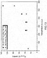
- the Applicant has also analyzed the evolution of the mesh parameter of the In x Ga 1-x As substrate as a function of the indium (x) content reported in figure 11 to estimate a range of preferred mole fractions at the substrate composition for which the present invention is particularly suitable.
- texture B which is the least favorable.
- This figure is constructed from an approximation: it is the reference intermetallic Ni 3 In 0.53 Ga 0.47 As which is used to evaluate the mesh mismatch whatever the indium content.
- the stoichiometry of the intermetallic changes as a function of the indium content of the substrate (for example, the intermetallic Ni 3 In 0.7 Ga 0.3 As is formed on a substrate containing 70% indium).
- two other points were added to the figure 12 these are the mesh mismatch values for the Ni 3 GaAs intermetallic on GaAs.
- Example of a process of the invention comprising the production of an intermetallic contact formed from Ni on a substrate of In 0.53 Ga 0.47 As :
- a substrate surface of In 0.53 Ga 0.47 As is treated with a solution of HCl: H 2 O (1:10 to 1: 2, preferably 1:10) for 45 to 60 seconds in order to remove the native oxides (In 2 O 3 , Ga 2 O 3 , As 2 O 3 , As 2 O 5 ).
- the semiconductor layer of In 0.53 Ga 0.47 As is then treated in an in-situ cleaning chamber (commonly called "preclean") by an Ar or He plasma in order to remove any oxides that would have recreated between the liquid phase treatment ( commonly referred to as "WET”) and the evacuation of samples prior to metal deposition.
- preclean in-situ cleaning chamber
- a Ni deposition (7 to 80 nm) is carried out on the In 0.53 Ga 0.47 As layer. It is advantageous to deposit a protective layer that may be TiN (7 nm or more ) in order to preserve the sample of any oxidation on the surface of the metal or at the metal / semiconductor interface.
- the metal layer / semiconductor substrate assembly is treated during an annealing step under a controlled atmosphere. It is the progress of this annealing step that is essential to control the texture and phase of the intermetallic that will be formed.
- intermetallic compound having the best performance can be obtained by a one-step or two-step process (with or without complete consumption of Ni).
- a selective removal step is essential.
- the first step (low temperature annealing) makes it possible to control the texture of the intermetallic and thus the morphology of the interface.
- a second high-temperature annealing step makes it possible to change the phase formed during the first step to the least resistive phase without modifying its texture (and thus the interface morphology).
- the Applicant has shown that to promote the texture that will grow the intermetallic compound parallel to the substrate (in opposition to the texture that leads to obtaining a pyramidal material) it was necessary to heat the sample at low temperature. (200 ° C and 320 ° C, with a preference for the range 240 ° C and 290 ° C) for a time long enough to allow the diffusion and total consumption of Ni (this time depends on the thickness of the coating layer). Neither initial, it can vary from a few minutes for a layer of 7 nm to a few tens of minutes for a layer of 80 nm). The Ni 3 InGaAs phase is obtained during this annealing.
- a second RTA (Rapid Thermal Annealing) annealing can be performed to control the phase of the intermetallic compound: 250 ⁇ RTA ⁇ 350 ° C to obtain the Ni 3 phase In 0.53 Ga 0.47 As or 350 ⁇ RTA ⁇ 500 ° C to obtain the Ni 2 In 0.53 Ga 0.47 As phase. From a point of view of contact resistivity, the phase Ni 3 In 0.53 Ga 0.47 As nevertheless seems the more favorable. Above 500 ° C, there is a rejection of the Ga and In atoms which leads to obtaining InAs clusters clearly unfavorable in terms of contact resistivity.
- the figure 14 shows the results obtained for the contact resistivity in the framework of Ni (20 nm) on stacking In 0.53 Ga 0.47 As / InP. It also appears that the contact resistivity is sufficiently low with compounds obtained with annealing temperatures of less than 500 ° C., advantageously less than 450 ° C.
Landscapes
- Engineering & Computer Science (AREA)
- Microelectronics & Electronic Packaging (AREA)
- Power Engineering (AREA)
- Physics & Mathematics (AREA)
- Condensed Matter Physics & Semiconductors (AREA)
- General Physics & Mathematics (AREA)
- Computer Hardware Design (AREA)
- Ceramic Engineering (AREA)
- Manufacturing & Machinery (AREA)
- Electrodes Of Semiconductors (AREA)
- Testing Or Measuring Of Semiconductors Or The Like (AREA)
- Manufacture Of Switches (AREA)
Abstract
L'invention a pour objet un procédé de fabrication de contact intermétallique à la surface d'une couche ou d'un substrat de matériau InxGa1-xAs orientée (100, ledit contact comprenant un composé intermétallique de Ni-lnGaAs ledit composé intermétallique ayant une structure cristallographique hexagonale pouvant présenter :
- une première texture ou
- une seconde texture formée à une seconde température de nucléation supérieure à ladite première température de nucléation ;
ledit procédé comprenant les étapes suivantes :
- l'élaboration d'abaques définissant pour une épaisseur de Ni déposé, le temps pour consommer totalement l'épaisseur initiale de Ni en fonction de la température de recuit, ladite température de recuit étant inférieure à ladite température de nucléation de ladite seconde texture ;
- le dépôt localisé de Ni à la surface dudit matériau InxGa1-xAs ;
- une étape de recuit appliquant le couple de paramètres : temps nécessaire/ température de recuit, déduit desdites abaques, comprenant au moins une étape de montée en température et au moins un plateau de maintien en température de ladite température finale de recuit.

- a first texture or
a second texture formed at a second nucleation temperature greater than said first nucleation temperature;
said method comprising the following steps:
the production of abacuses defining, for a thickness of Ni deposited, the time to completely consume the initial thickness of Ni as a function of the annealing temperature, said annealing temperature being lower than said nucleation temperature of said second texture;
the localized deposit of Ni on the surface of said In x Ga 1-x As material;
an annealing step applying the pair of parameters: time required / annealing temperature, deduced from said charts, comprising at least one temperature rise step and at least one temperature holding plate of said final annealing temperature.
Description
Le domaine de l'invention est celui des composants en matériaux III-V et plus précisément celui des composants InxGa1-xAs avec 0 ≤ x ≤ 1, comprenant la réalisation de contacts intermétalliques.The field of the invention is that of the components in materials III-V and more precisely that of the components In x Ga 1-x As with 0 ≤ x ≤ 1, comprising the realization of intermetallic contacts.
La
Les contacts sur InxGa1-xAs avec 0 ≤ x ≤ 1 compatibles avec une technologie Si-CMOS sont généralement réalisés par réaction à l'état solide entre un métal (Ni) ou un alliage métallique NiyM1-y et le semi-conducteur (InGaAs) comme décrit dans la publication de
Cette réaction réalisée entre 200 et 500 °C par un recuit rapide sous atmosphère contrôlée conduit à l'obtention d'un composé intermétallique Ni-InGaAs, comme décrit dans la publication de
Jusqu'à ce jour, la nature des phases et des textures obtenues lors de la réaction à l'état solide entre le Ni et InGaAs était mal connue comme décrit dans la publication de
Or une maitrise de ces dernières peut conduire à l'obtention d'un composé intermétallique optimisé, notamment en termes de stabilité morphologique, d'épaisseur et de résistivité de contact permettant une maitrise de l'élaboration des contacts.However, a mastery of these can lead to obtaining an optimized intermetallic compound, particularly in terms of morphological stability, thickness and contact resistivity allowing control of the development of contacts.
C'est pourquoi dans ce contexte, la présente invention a pour objet un procédé de fabrication de contact intermétallique optimisé.Therefore, in this context, the present invention relates to an optimized intermetallic contact manufacturing method.
Le Demandeur propose un procédé permettant de contrôler les phases et les textures du composé intermétallique Ni-InGaAs , basé sur une étude approfondie de la réaction à l'état solide entre le métal Ni et le composé InxGa1-xAs avec 0 ≤ x ≤ 1 et ce afin de favoriser :
- une texture conduisant à une interface de contact et une morphologie optimisées ;
- une phase hexagonale à stoechiométrie bien définie favorable en termes de résistivité de contact.
- a texture leading to an optimized contact interface and morphology;
- a hexagonal phase with a well-defined stoichiometry favorable in terms of contact resistivity.
L'intérêt de la présente invention réside dans le fait de réaliser un procédé d'obtention de composé intermétallique qui permette de rester en dessous de la barrière de nucléation de la texture non favorable tant que tout le Ni n'a pas été consommé.The advantage of the present invention lies in the fact of producing a process for obtaining an intermetallic compound which makes it possible to remain below the nucleation barrier of the unfavorable texture until all the Ni has been consumed.
Par rapport à l'état de l'art, la présente invention apporte une solution permettant de maitriser de façon reproductible la morphologie des contacts au travers du contrôle de la texture et de la phase et donc de favoriser une plus faible résistivité.Compared to the state of the art, the present invention provides a solution for reproducibly mastering the morphology of the contacts through the control of texture and phase and thus to promote a lower resistivity.
La présente invention concerne un procédé permettant par une opération de recuit thermique calibré en fonction de l'épaisseur de nickel déposée, de ne former qu'un type de première texture souhaitée tout en évitant de former une seconde texture indésirable comme il sera explicité et développé dans la description détaillée de la présent demande.The present invention relates to a method allowing by a thermal annealing operation calibrated according to the deposited nickel thickness, to form only one type of desired first texture while avoiding forming a second undesirable texture as it will be explained and developed in the detailed description of this application.
Plus précisément l'invention a pour objet un procédé de fabrication de contact intermétallique à la surface d'une couche ou d'un substrat de matériau InxGa1-xAs orientée (100) avec 0 ≤ x ≤ 1, ledit contact comprenant un composé intermétallique de Ni-InGaAs ledit composé intermétallique ayant une structure cristallographique hexagonale pouvant présenter :
- une première texture dont des plans (10
1 0) du composé intermétallique sont parallèles à la surface de ladite couche ou dudit substrat et formée à une première température de nucléation ou - une seconde texture dont les plans (0001) du composé intermétallique sont parallèles aux plans (111) de ladite couche ou dudit substrat et formée à une seconde température de nucléation supérieure à ladite première température de nucléation ;
- l'élaboration d'abaques définissant pour une épaisseur de Ni déposé sur ledit matériau InxGa1-xAs, le temps nécessaire pour consommer totalement l'épaisseur initiale de Ni déposé sur ledit matériau InxGa1-xAs en fonction de la température de recuit, ladite température de recuit étant inférieure à ladite température de nucléation de ladite seconde texture ;
- le dépôt localisé de Ni à la surface dudit matériau InxGa1-xAs pour former une couche de Ni présentant une épaisseur de contact ;
- une étape de recuit appliquant le couple de paramètres : temps nécessaire/ température de recuit, déduit desdites abaques en corrélation avec ladite épaisseur de contact de manière à former par réaction à l'état solide une couche de composé intermétallique de première texture, ladite étape de recuit comprenant :
- ∘ au moins une étape de montée en température avec une vitesse de montée en température déterminée permettant d'atteindre une température finale de recuit Tp et
- ∘ au moins un plateau de maintien en température de ladite température finale de recuit Tp, pendant une durée de plateau Δtp.
- a first texture including plans ( 10
1 0 ) of the intermetallic compound are parallel to the surface of said layer or substrate and formed at a first nucleation temperature or - a second texture whose planes ( 0001 ) of the intermetallic compound are parallel to the planes (111) of said layer or said substrate and formed at a second nucleation temperature higher than said first nucleation temperature;
- the development of abacuses defining for a thickness of Ni deposited on said In x Ga 1-x As material, the time necessary to consume completely the initial thickness of Ni deposited on said In x Ga 1-x As material as a function of the annealing temperature, said annealing temperature being lower than said nucleation temperature of said second texture;
- localized deposition of Ni on the surface of said In x Ga 1-x As material to form a Ni layer having a contact thickness;
- an annealing step applying the pair of parameters: time required / annealing temperature, deduced from said graphs in correlation with said contact thickness so as to form, by reaction in the solid state, a layer of intermetallic compound of first texture, said step of annealing comprising:
- At least one step of raising the temperature with a determined rate of rise in temperature making it possible to reach a final annealing temperature T p and
- ∘ at least one plateau for maintaining the temperature of said final annealing temperature T p during a plateau duration Δt p .
Avantageusement, la vitesse de montée en température est déterminée inférieure à une vitesse maximale Vmax, ladite vitesse maximale dépendant de la cinétique de la texture qui se forme.Advantageously, the rate of rise in temperature is determined lower than a maximum speed V max , said maximum speed depending on the kinetics of the texture that is formed.
Avantageusement, la vitesse maximale de recuit (en °C / min) répond à l'équation suivante en fonction de l'épaisseur de Ni déposée (en nm) : ![]()
![]()
Avantageusement, le procédé de l'invention peut comprendre concernant l'étape de recuit :
- une première étape de montée en température avec une première vitesse de montée en température permettant d'atteindre une première température de recuit T1r ;
- une deuxième étape de montée en température avec une deuxième vitesse de montée en température permettant d'atteindre depuis ladite première température de recuit, une température finale de recuit Tp ;
- au moins un plateau de maintien en température de ladite température finale de recuit Tp pendant une durée de plateau Δtp.
- a first step of raising temperature with a first rate of rise in temperature making it possible to reach a first annealing temperature T 1r ;
- a second step of raising temperature with a second rate of rise in temperature making it possible to reach, from said first annealing temperature, a final annealing temperature T p ;
- at least one plateau for maintaining the temperature of said final annealing temperature T p during a plateau duration Δt p .
Avantageusement la fraction molaire x du substrat est comprise entre 0,25 et 0,80.Advantageously, the mole fraction x of the substrate is between 0.25 and 0.80.
Selon des variantes de l'invention, le procédé comprend un premier recuit à une première température durant une première durée pour former un premier composé intermétallique de première texture et présentant une première phase et un second recuit à une température plus élevée que ladite première température pour former un second composé intermétallique de première texture et présentant une seconde phase.According to variants of the invention, the method comprises a first annealing at a first temperature during a first duration to form a first intermetallic compound of first texture and having a first phase and a second annealing at a temperature higher than said first temperature for forming a second intermetallic compound of first texture and having a second phase.
Le composé intermétallique Ni-InGaAs peut typiquement être un composé Ni2InGaAs ou un composé Ni3InGaAs.The Ni-InGaAs intermetallic compound may typically be a Ni 2 InGaAs compound or a Ni 3 InGaAs compound.
Selon des variantes de l'invention le procédé comprend un recuit effectué à une température comprise entre 200°C et 320°C, pour former la première texture A, avec une préférence pour la gamme 240°C et 290°C pendant une durée dépendante de l'épaisseur de Ni déposée, pour former un composé intermétallique de Ni3InGaAs.According to variants of the invention, the process comprises an annealing carried out at a temperature of between 200 ° C. and 320 ° C., to form the first texture A, with a preference for the range 240 ° C. and 290 ° C. for a time dependent period. of the deposited Ni thickness, to form an intermetallic compound of Ni 3 InGaAs.
Typiquement pour une épaisseur initiale de Ni comprise entre quelques nanomètres et quelques dizaines de nanomètres, la durée de recuit peut varier entre quelques minutes et quelques dizaines de minutes.Typically for an initial thickness of Ni between a few nanometers and a few tens of nanometers, the annealing time can vary between a few minutes and a few tens of minutes.
Selon des variantes de l'invention, ledit recuit effectué à une température comprise entre 200°C et 320°C, avec une préférence pour la gamme 240°C et 290°C est suivi d'un recuit effectué à une température comprise entre 250 °C et 550 °C pour modifier la résistivité dudit contact intermétallique formé.According to variants of the invention, said annealing carried out at a temperature of between 200 ° C. and 320 ° C., with a preference for the range 240 ° C. and 290 ° C., is followed by an annealing carried out at a temperature of between 250 ° C. and 250 ° C. ° C and 550 ° C to change the resistivity of said formed intermetallic contact.
Selon des variantes de l'invention, ledit recuit effectué à une température comprise entre 200°C et 320°C, avec une préférence pour la gamme 240°C et 290°C est suivi d'un recuit effectué à une température comprise entre 300 °C et 500 °C pour consolider la phase Ni3InGaAs (dans la fourchette basse) ou former la phase Ni2InGaAs (dans la fourchette haute).According to variants of the invention, said annealing carried out at a temperature of between 200 ° C. and 320 ° C., with a preference for the range 240 ° C. and 290 ° C., is followed by annealing carried out at a temperature of between 300 ° C. ° C and 500 ° C to consolidate the Ni 3 InGaAs phase (in the low range) or form the Ni 2 InGaAs phase (in the high range).
Il est à noter que les 2 phases Ni3InGaAs et Ni2InGaAs présentent la même structure avec des compositions variables selon le taux d'occupation des sites interstitiels, la phase Ni2InGaAs étant la phase la plus stable à haute température (350 - 500 °C).It should be noted that the two Ni 3 InGaAs and Ni 2 InGaAs phases have the same structure with compositions that vary according to the occupancy rate of the interstitial sites, the Ni 2 InGaAs phase being the most stable phase at high temperature (350.degree. 500 ° C).
Selon des variantes de l'invention, les abaques sont élaborés en mesurant les épaisseurs de composé intermétallique formées en fonction du temps.According to variants of the invention, the charts are produced by measuring the thicknesses of intermetallic compound formed as a function of time.
Selon des variantes de l'invention, les mesures d'épaisseur sont réalisées par réflectivité de rayons X.According to variants of the invention, the thickness measurements are carried out by X-ray reflectivity.
Selon des variantes de l'invention, les mesures d'épaisseur sont réalisées par ellipsométrie.According to variants of the invention, the thickness measurements are made by ellipsometry.
Selon des variantes de l'invention, le procédé comprend le dépôt d'une couche protectrice à la surface du dépôt localisé de Ni, préalablement à(aux) l'opération(s) de recuit.According to variants of the invention, the method comprises depositing a protective layer on the surface of the localized deposit of Ni, prior to (the) operation (s) of annealing.
L'invention a aussi pour objet le contact intermétallique obtenu selon le procédé de l'invention.The invention also relates to the intermetallic contact obtained according to the method of the invention.
L'invention a encore pour objet un procédé de fabrication d'un transistor comprenant le procédé de fabrication de contact intermétallique de l'invention.The invention further relates to a method for manufacturing a transistor comprising the intermetallic contact manufacturing method of the invention.
L'invention a aussi pour objet un procédé de fabrication d'un composant photonique comprenant le procédé de fabrication de contact intermétallique de l'invention.The invention also relates to a method of manufacturing a photonic component comprising the intermetallic contact manufacturing method of the invention.
L'invention sera mieux comprise et d'autres avantages apparaîtront à la lecture de la description qui va suivre donnée à titre non limitatif et grâce aux figures parmi lesquelles :
- La
figure 1 illustre un exemple de structure de transistor selon l'art connu pouvant comprendre des contacts intermétalliques ; - La
figure 2 illustre un exemple de structure photonique selon l'art connu pouvant comprendre des contacts intermétalliques ; - la
figure 3 schématise les deux textures du composé intermétallique Ni-InGaAs pouvant être obtenues lors d'une opération de recuit ; - les
figures 4a et 4b illustrent deux options de l'invention avec une rampe ou deux rampes de recuit, dans le cas d'un dépôt de Ni de 10 nm ; - les
figures 5a-5c illustrent l'apparition de la seconde texture au-delà de la température de nucléation de la seconde texture, en fonction de la vitesse de recuit pour une épaisseur de Ni de 7nm ; - les
figures 6a-6c illustrent l'apparition de la seconde texture au-delà de la température de nucléation de la seconde texture, en fonction de la vitesse de recuit pour une épaisseur de Ni de 10nm ; - les
figures 7a-7c illustrent l'apparition de la seconde texture au-delà de la température de nucléation de la seconde texture, en fonction de la vitesse de recuit pour une épaisseur de Ni de 20 nm ; - les
figures 8a-8c illustrent de manière générique les précédentes figures, en matérialisant par des zones hachurées, les zones à exclure (zone où la texture B est susceptible de se former) ; - la
figure 9 illustre la fonction que le Demandeur a établi fournissant cette vitesse maximale de recuit Vmax (en °C/min) en fonction de l'épaisseur de Ni (en nm); - la
figure 10 illustre les différentes phases de composés intermétalliques formés en fonction de la température dans le cas d'une réaction solide entre Ni et InxGa1-xAs ; - la
figure 11 illustre l'évolution du paramètre de maille du substrat InxGa1-xAs en fonction de la teneur en indium (x) ; - la
figure 12 illustre l'évolution du désaccord de maille pour les 2 textures de l'intermétallique Ni3In0.53Ga0.47As en fonction de la teneur en indium du substrat ; - la
figure 13 illustre l'évolution de la résistance carrée de contact d'un exemple de couche formée de Ni-In0.53Ga0.47As en fonction de la température de recuit ; - la
figure 14 illustre l'évolution de la résistivité de contact d'un exemple de couche formée de Ni-In0.53Ga0.47As en fonction de la température de recuit.
- The
figure 1 illustrates an example of a transistor structure according to the prior art which may comprise intermetallic contacts; - The
figure 2 illustrates an example of a photonic structure according to the known art that may comprise intermetallic contacts; - the
figure 3 schematizes the two textures of the intermetallic compound Ni-InGaAs obtainable during an annealing operation; - the
Figures 4a and 4b illustrate two options of the invention with a ramp or two annealing ramps, in the case of a deposition of 10 nm Ni; - the
Figures 5a-5c illustrate the appearance of the second texture beyond the nucleation temperature of the second texture, in annealing speed function for a Ni thickness of 7 nm; - the
Figures 6a-6c illustrate the appearance of the second texture beyond the nucleation temperature of the second texture, as a function of the annealing speed for a Ni thickness of 10 nm; - the
Figures 7a-7c illustrate the appearance of the second texture beyond the nucleation temperature of the second texture, as a function of the annealing rate for a Ni thickness of 20 nm; - the
Figures 8a-8c illustrate in a generic way the preceding figures, by materializing by hatched zones, the areas to be excluded (zone where the texture B is likely to form); - the
figure 9 illustrates the function that the Applicant has established providing this maximum annealing speed V max (in ° C / min) as a function of the thickness of Ni (in nm); - the
figure 10 illustrates the different phases of intermetallic compounds formed as a function of temperature in the case of a solid reaction between Ni and In x Ga 1-x As; - the
figure 11 illustrates the evolution of the mesh parameter of the In x Ga 1-x As substrate as a function of the indium (x) content; - the
figure 12 illustrates the evolution of the mesh mismatch for the 2 textures of the intermetallic Ni 3 In 0.53 Ga 0.47 As as a function of the indium content of the substrate; - the
figure 13 illustrates the evolution of the square contact resistance of an example of a layer formed of Ni-In 0.53 Ga 0.47 As as a function of the annealing temperature; - the
figure 14 illustrates the evolution of the contact resistivity of an example of a layer formed of Ni-In 0.53 Ga 0.47 As as a function of the annealing temperature.
De manière générale, lorsque l'on réalise un contact intermétallique à partir du dépôt de Ni à la surface d'une couche ou d'un substrat de InxGa1-xAs, la réaction à l'état solide entre Ni et InxGa1-xAs conduit à l'obtention de plusieurs composés intermétalliques Ni-InGaAs présentant une structure cristallographique : hexagonale type B8. Comme certains composés intermétalliques, cette phase hexagonale présente 2 textures (A et B) qui se caractérisent par leurs orientations par rapport au substrat.In general, when an intermetallic contact is made from the deposition of Ni on the surface of a layer or substrate of In x Ga 1 -x As, the solid state reaction between Ni and In x Ga 1-x As leads to the production of several Ni-InGaAs intermetallic compounds having a crystallographic structure: hexagonal type B8. Like some intermetallic compounds, this hexagonal phase has 2 textures (A and B) which are characterized by their orientations relative to the substrate.
Pour la texture A, les plans (10
Cela conduit dans le premier cas à l'obtention d'un hexagone dont l'axe c est parfaitement parallèle à la surface de la couche ou du substrat (texture A) et donc une interface Ni-InGaAs / InxGa1-xAs parfaitement plane, et dans l'autre cas à un hexagone qui est orienté selon les plans (111) de la couche ou du substrat donnant une interface très rugueuse et pouvant entrainer des défauts électriques (percement de jonction, augmentation de résistivité de contact). Ceci est schématisé sur la
Le Demandeur a mené des expériences permettant de démontrer que la texture du composé intermétallique peut être contrôlée par le budget thermique ou l'épaisseur de métal (si l'on est amené à fixer le budget thermique) mis en oeuvre lors de la réaction à l'état solide entre le Ni et InxGa1-xAs et a conclu qu'il convient de consommer la totalité du Ni avant de dépasser la température de nucléation de la texture B. Cette température est comprise entre 200°C et 320°C, avec une préférence pour la gamme 240°C et 290°C selon la teneur en In dans InxGa1-xAs.The Applicant has carried out experiments making it possible to demonstrate that the texture of the intermetallic compound can be controlled by the heat budget or the metal thickness (if it is necessary to fix the thermal budget) implemented during the reaction to the reaction. solid state between the Ni and In x Ga 1-x As and concluded that it is necessary to consume all of the Ni before exceeding the nucleation temperature of the texture B. This temperature is between 200 ° C and 320 ° C, with a preference for the range 240 ° C and 290 ° C depending on the content of In in In x Ga 1-x As.
La durée du recuit à appliquer pour consommer totalement le Ni dépend de la température du recuit et de l'épaisseur initiale de Ni déposé.The duration of the annealing to be applied to consume the Ni completely depends on the annealing temperature and the initial thickness of Ni deposited.
Selon la présente invention, il est proposé d'élaborer des abaques qui permettent de déterminer en fonction de l'épaisseur initiale de Ni et de la température du recuit, le temps nécessaire pour consommer tout le Ni.According to the present invention, it is proposed to develop abacuses that make it possible to determine, as a function of the initial thickness of Ni and the annealing temperature, the time required to consume all the Ni.
Plus précisément, le Demandeur a mis en évidence l'influence de l'opération de recuit sur la formation de la texture souhaitée, sans former la texture indésirable, et ce en contrôlant la vitesse de montée en température pour atteindre la température désirée de recuit appelée température finale de recuit, et le maintien de cette température au cours d'un plateau et ce en fonction de l'épaisseur de nickel.More specifically, the Applicant has demonstrated the influence of the annealing operation on the formation of the desired texture, without forming the undesirable texture, and this by controlling the rate of rise in temperature to reach the desired annealing temperature called final temperature of annealing, and the maintenance of this temperature during a tray and this depending on the thickness of nickel.
Le Demandeur a étudié deux options de recuit possibles, respectivement relatives à :
- une étape de recuit présentant une rampe 1 en température et un plateau, correspondant à l'option la plus simple ;
- une étape de recuit présentant une rampe 1, suivie d'une rampe 2 et d'un plateau, correspondant à une option plus industrialisable.
- an annealing step having a
ramp 1 in temperature and a plateau, corresponding to the simplest option; - an annealing step having a
ramp 1, followed by aramp 2 and a tray, corresponding to a more industrializable option.
Les
La plage de température de plus basse résistance de contact est située entre 300°C et 350°C.The temperature range of lower contact resistance is between 300 ° C and 350 ° C.
Il est nécessaire d'avoir obtenu une consommation totale de Ni dans la plage 200°C et 320°C, avec une préférence pour la gamme 240°C et 290°C pour éviter de former la seconde texture dite B.It is necessary to have obtained a total consumption of Ni in the
Une méthode globale consiste à mesurer l'épaisseur de composé intermétallique formé (ou du Ni consommé) en fonction du temps pour différentes températures de recuit. Cette mesure d'épaisseur peut être réalisée par différentes méthodes de caractérisation : par une analyse par réflectivité de rayons X (couramment dénommée XRR, pour X-Ray Reflectivity), par ellipsométrie, microscopie, etc... ou toutes méthodes permettant d'extraire l'épaisseur du composé intermétallique et celle du Ni. L'épaisseur L de composé intermétallique formé est généralement proportionnelle au taux de formation D multiplié par le temps t, le tout à un facteur puissance n (n étant compris entre ½ et 4) comme défini ci-après : ![]()
![]()
Suivant la méthode décrite précédemment, on peut donc aisément déterminer des taux de formation pour différentes températures et par modélisation obtenir le temps nécessaire pour consommer totalement le nickel pour une épaisseur initiale et une température de recuit données.According to the method described above, it is therefore easy to determine formation rates for different temperatures and by modeling to obtain the time necessary to consume the nickel completely for an initial thickness and a given annealing temperature.
Ainsi, suivant cette méthodologie et à partir de données recueillies dans la littérature, telles que décrites dans les publications de
Plus précisément, Chuang et al. mesurent des épaisseurs de GaAs consommé pour une température et différents temps, Solomon et Smith mesurent des gradients de concentration de Ni en fonction de la température pour un temps donné. Les deux en déduisent des coefficients de diffusion du Ni dans GaAs (ou taux de formation).Specifically, Chuang et al. measure thicknesses of GaAs consumed for a temperature and different times, Solomon and Smith measure Ni concentration gradients as a function of the temperature for a given time. Both deduce Ni diffusion coefficients in GaAs (or formation rate).
Le Demandeur a réalisé différentes études pour déterminer les paramètres permettant d'optimiser l'opération de recuit tout en ne formant que la première texture A, en évitant de former la seconde texture B.The Applicant has carried out various studies to determine the parameters making it possible to optimize the annealing operation while forming only the first texture A, avoiding forming the second texture B.
Les
Plus précisément :
- les
figures 5a-5c sont relatives à une épaisseur de Ni de 7nm ; - les
figures 6a-6c sont relatives à une épaisseur de Ni de 10nm ; - les
figures 7a-7c sont relatives à une épaisseur de Ni de 20 nm.
- the
Figures 5a-5c are relative to a thickness of Ni of 7nm; - the
Figures 6a-6c are relative to a Ni thickness of 10 nm; - the
Figures 7a-7c are relative to a Ni thickness of 20 nm.
Les
La bande hachurée grise horizontale correspond à la température de nucléation Tnucl du type B de la seconde texture.The horizontal gray hatched band corresponds to the nucleation temperature T nucl of type B of the second texture.
La zone hachurée correspond à la zone potentielle où le type de seconde texture B peut croitre si elle intercepte la courbe ENi du Ni avant consommation complète.The shaded area corresponds to the potential area where the type of second texture B can grow if it intercepts the Ni Ni curve Ni before complete consumption.
La courbe représentant la rampe R doit couper la zone de nucléation (zone hachurée) une fois que tout le Ni est consommé (courbe ENi) afin de favoriser uniquement la formation de la première texture de type A.The curve representing the ramp R must cut the nucleation zone (shaded area) once all the Ni is consumed (E Ni curve) to promote only the formation of the first texture type A.
La
La
Le Demandeur a ainsi pu établir le Tableau ci-dessous liant les rampes limites (correspondant à une vitesse maximale de montée en température) en fonction de l'épaisseur.
Plus l'épaisseur est grande plus la rampe doit être faible et donc plus un temps de recuit long est nécessaire.The greater the thickness, the slower the ramp must be, and therefore a longer annealing time is required.
La fonction qui lie la rampe maximale (en °C/min) utilisable avec l'épaisseur de Ni déposée (en nm) est une fonction puissance : ![]()
![]()
Les coefficients de cette fonction dépendent de la cinétique de la phase qui se forme.The coefficients of this function depend on the kinetics of the phase that is formed.
La
Le Demandeur fournit des plages de durées, (il est indiqué que les temps totaux : rampe + plateau, n'intègrent pas les temps de refroidissement, la durée du plateau étant de 60 s). Le temps minimal correspond typiquement à la pente Vmax du cas limite .The Applicant provides ranges of durations, (it is indicated that the total times: ramp + plateau, do not integrate the times of cooling, the shelf life being 60 s). The minimum time typically corresponds to the slope V max of the limit case.
- Temps minimal : 70 sMinimum time: 70 s
- Vitesse de Rampe : 300°C/minRamp Speed: 300 ° C / min
- Temps total : 130 sTotal time: 130 s
- Temps minimal : 140 sMinimum time: 140 s
- Vitesse de Rampe : 150°C/minRamp Speed: 150 ° C / min
- Temps total : 200 sTotal time: 200 s
- Temps minimal : 600 sMinimum time: 600 s
- Vitesse de Rampe : 35°C/minRamp Speed: 35 ° C / min
- Temps total : 660 sTotal time: 660 s
L'intérêt d'une double rampe réside dans le fait de réduire le temps total du cas minimal (pour une épaisseur donnée).The advantage of a double ramp lies in reducing the total time of the minimal case (for a given thickness).
- Temps minimal : 56 sMinimum time: 56 s
- Vitesse de Rampe R1 : 300°C/minRamp Speed R1: 300 ° C / min
- Durée de Rampe R2 : 10 sRamp duration R2: 10 s
- Temps total : 126 sTotal time: 126 s
- Temps minimal : 112 sMinimum time: 112 s
- Vitesse de Rampe R1 : 150°C/minRamp Speed R1: 150 ° C / min
- Durée de Rampe R2 : 10 sRamp duration R2: 10 s
- Temps total : 182 sTotal time: 182 s
- Temps minimal : 480 s
- Vitesse de Rampe R1 : 35°C/min
- Durée de Rampe R2 : 10 s
- Temps total : 550 s
- Minimum time: 480 sec
- Ramp Speed R1: 35 ° C / min
- Ramp duration R2: 10 s
- Total time: 550 s
Le Tableau 1 ci-dessous répertorie l'ensemble des résultats pour différentes épaisseurs initiales de Ni.
Il est à noter que l'on trouve des taux de formation différents selon les publications qui peuvent s'expliquer par l'incertitude sur la mesure de l'épaisseur et l'incertitude sur la température de recuit.It should be noted that there are different formation rates according to the publications that can be explained by the uncertainty in the measurement of the thickness and the uncertainty on the annealing temperature.
Il donc nécessaire de réaliser ces abaques en tenant compte des équipements utilisés.It is therefore necessary to make these charts taking into account the equipment used.
Il a par ailleurs, était reporté que la diffusion du Ni dans le composé GaAs ou celle du Ni dans le composé In0.53Ga0.47As étaient très similaires dans l'article de
Selon la présente invention, il est donc proposé d'établir des abaques définissant pour une épaisseur donnée de Ni, le couple de paramètres : température de recuit/temps de recuit pour consommer complètement une épaisseur donnée de Ni et d'appliquer ces couples de paramètres pour conduire à la formation d'un composé intermétallique de bonne texture, c'est-à-dire la première texture A présentant des propriétés optimales de surface de contact.According to the present invention, it is therefore proposed to establish abacuses defining for a given thickness of Ni, the pair of parameters: annealing temperature / annealing time to completely consume a given thickness of Ni and to apply these pairs of parameters. to result in the formation of an intermetallic compound of good texture, i.e., the first texture A having optimum surface area properties.
Selon le procédé de la présente invention, il est ainsi possible de contrôler la texture permettant de garantir le meilleur contact, la résistance de contact métal/semi-conducteur (InxGa1-xAs dans le cas présent) dépendant de la hauteur de barrière de Schottky et donc de la phase, donc de la stoechiométrie, en contact avec le semi-conducteur.According to the method of the present invention, it is thus possible to control the texture to ensure the best contact, the contact resistance metal / semiconductor (In x Ga 1-x As in this case) depending on the height of Schottky barrier and therefore the phase, therefore the stoichiometry, in contact with the semiconductor.
Le Demandeur a montré que dans le système considéré plusieurs phases peuvent se former : Ni3InGaAs, Ni2InGaAs, NiAs.The Applicant has shown that in the considered system several phases can be formed: Ni 3 InGaAs, Ni 2 InGaAs, NiAs.
Le Demandeur s'est intéressé à la première phase et la texture A. L'obtention de la texture A se fait avec un faible budget thermique et la phase Ni3InGaAs nécessite un recuit dont la température est inférieure à 350 °C. La
Le Demandeur a également analysé l'évolution du paramètre de maille du substrat InxGa1-xAs en fonction de la teneur en indium (x) reportée en
Cette évolution est basée sur l'application de la loi de Vegard entre les 2 cas extrêmes GaAs et InAs ainsi que la composition intermédiaire In0.53Ga0.47As.This evolution is based on the application of the Vegard law between the 2 extreme GaAs and InAs cases as well as the intermediate composition In 0.53 Ga 0.47 As.
A l'aide de l'équation de droite extraite de la figure A, le paramètre de maille du substrat InxGa1-xAs a pu être calculé pour x variant de 0 à 100 puis la distance interréticulaire entre les plans (110) et (111) a été calculée selon la formule usuelle pour une maille cubique : 
Les résultats sont reportés dans le tableau A qui fournit la valeur des distances interréticulaires pour les plans (110) et (111) du substrat InxGa1-xAs en fonction de la teneur en indium (x).

L'intermétallique de référence Ni3In0.53Ga0.47As / In0.53Ga0.47As présente les paramètres de maille (maille hexagonale) suivants : a = 3.87 et c = 5.03. A partir de ces paramètres, on peut calculer les distances interréticulaires pour les plans (10
Pour cet intermétallique de référence, on peut calculer le désaccord de maille pour chacune des deux textures en fonction de la teneur en indium du substrat. Ceci est illustré par la
Le procédé comprend les étapes suivantes :
- Une étape de nettoyage du substrat ;
- Une étape de dépôt métallique de Ni ;
- Une ou plusieurs étape(s) de recuit permettant la formation de composé intermétallique avec la texture A à basse température et en consommant tout le Ni présent.
- A step of cleaning the substrate;
- A step of depositing Ni metal;
- One or more annealing step (s) allowing the formation of intermetallic compound with the texture A at low temperature and consuming all the Ni present.
Une surface de substrat de In0.53Ga0.47As est traitée par une solution d'HCl:H2O (1:10 à 1:2, préférentiellement 1:10) pendant 45 à 60 s afin de retirer les oxydes natifs (In2O3, Ga2O3, As2O3, As2O5...). La couche semi-conductrice de In0.53Ga0.47As est ensuite traitée dans une chambre de nettoyage in situ (dénommé couramment « preclean ») par un plasma Ar ou He afin de retirer les éventuels oxydes qui auraient recrû entre le traitement en phase liquide (dénommé couramment « WET ») et la mise sous vide des échantillons avant dépôt du métal.A substrate surface of In 0.53 Ga 0.47 As is treated with a solution of HCl: H 2 O (1:10 to 1: 2, preferably 1:10) for 45 to 60 seconds in order to remove the native oxides (In 2 O 3 , Ga 2 O 3 , As 2 O 3 , As 2 O 5 ...). The semiconductor layer of In 0.53 Ga 0.47 As is then treated in an in-situ cleaning chamber (commonly called "preclean") by an Ar or He plasma in order to remove any oxides that would have recreated between the liquid phase treatment ( commonly referred to as "WET") and the evacuation of samples prior to metal deposition.
Sans remise à l'air de l'échantillon, un dépôt de Ni (7 à 80 nm) est réalisé sur la couche d'In0.53Ga0.47As. On peut avantageusement déposer une couche protectrice pouvant être de TiN (7 nm ou plus) afin de préserver l'échantillon d'une éventuelle oxydation à la surface du métal ou à l'interface métal / semi-conducteur.Without re-airing the sample, a Ni deposition (7 to 80 nm) is carried out on the In 0.53 Ga 0.47 As layer. It is advantageous to deposit a protective layer that may be TiN (7 nm or more ) in order to preserve the sample of any oxidation on the surface of the metal or at the metal / semiconductor interface.
L'ensemble couche métallique/substrat semi-conducteur est traité lors d'une étape de recuit sous atmosphère contrôlée. C'est le déroulement de cette étape de recuit qui est primordial pour contrôler la texture et la phase de l'intermétallique qui sera formé.The metal layer / semiconductor substrate assembly is treated during an annealing step under a controlled atmosphere. It is the progress of this annealing step that is essential to control the texture and phase of the intermetallic that will be formed.
Le demandeur a montré que le composé intermétallique présentant les meilleures performances (rugosité d'interface et résistivité de contact) peut être obtenu grâce à un procédé en une étape ou en deux étapes (avec ou sans consommation complète du Ni). Dans le cas de 2 étapes sans consommation complète du Ni : une étape de retrait sélectif est indispensable.Applicant has shown that the intermetallic compound having the best performance (interface roughness and contact resistivity) can be obtained by a one-step or two-step process (with or without complete consumption of Ni). In the case of 2 stages without complete Ni consumption: a selective removal step is essential.
La première étape (recuit basse température) permet de contrôler la texture de l'intermétallique et donc la morphologie de l'interface.The first step (low temperature annealing) makes it possible to control the texture of the intermetallic and thus the morphology of the interface.
Une seconde étape de recuit haute température permet de faire éventuellement évoluer la phase formée lors de la première étape vers la phase la moins résistive sans modifier sa texture (et donc la morphologie d'interface).A second high-temperature annealing step makes it possible to change the phase formed during the first step to the least resistive phase without modifying its texture (and thus the interface morphology).
Plus précisément, le Demandeur a montré que pour favoriser la texture qui fera croitre le composé intermétallique de façon parallèle au substrat (en opposition avec la texture qui conduit à l'obtention d'un matériau pyramidal) il fallait chauffer l'échantillon à basse température (200°C et 320°C, avec une préférence pour la gamme 240°C et 290°C) pendant un temps suffisamment long pour permettre la diffusion et la consommation totale du Ni (ce temps dépend de l'épaisseur de la couche de Ni initiale, il peut varier de quelques minutes pour une couche de 7 nm à quelques dizaines de minutes pour une couche de 80 nm). La phase Ni3InGaAs est obtenue lors de ce recuit.Specifically, the Applicant has shown that to promote the texture that will grow the intermetallic compound parallel to the substrate (in opposition to the texture that leads to obtaining a pyramidal material) it was necessary to heat the sample at low temperature. (200 ° C and 320 ° C, with a preference for the range 240 ° C and 290 ° C) for a time long enough to allow the diffusion and total consumption of Ni (this time depends on the thickness of the coating layer). Neither initial, it can vary from a few minutes for a layer of 7 nm to a few tens of minutes for a layer of 80 nm). The Ni 3 InGaAs phase is obtained during this annealing.
Une fois que le film de Ni est totalement consommé, un second recuit de type RTA (Rapid Thermal Annealing) peut être opéré afin de contrôler la phase du composé intermétallique : 250 ≤ RTA < 350 °C pour l'obtention de la phase Ni3In0.53Ga0.47As ou 350 ≤ RTA < 500 °C pour l'obtention de la phase Ni2In0.53Ga0.47As. D'un point de vue résistivité de contact, la phase Ni3In0.53Ga0.47As semble néanmoins la plus favorable. Au-delà de 500 °C, on observe un rejet des atomes de Ga et d'In qui conduit à l'obtention de clusters d'InAs clairement non favorables en termes de résistivité de contact.Once the Ni film is completely consumed, a second RTA (Rapid Thermal Annealing) annealing can be performed to control the phase of the intermetallic compound: 250 ≤ RTA <350 ° C to obtain the Ni 3 phase In 0.53 Ga 0.47 As or 350 ≤ RTA <500 ° C to obtain the Ni 2 In 0.53 Ga 0.47 As phase. From a point of view of contact resistivity, the phase Ni 3 In 0.53 Ga 0.47 As nevertheless seems the more favorable. Above 500 ° C, there is a rejection of the Ga and In atoms which leads to obtaining InAs clusters clearly unfavorable in terms of contact resistivity.
La
- un dépôt métallique de Ni d'épaisseur initiale de 10 nm sur un empilement In0.53Ga0.47As sur Si ;
- un dépôt métallique de Ni d'épaisseur initiale de 7 nm sur un empilement de In0.53Ga0.47As sur InP.
- a metal deposition of Ni of initial thickness of 10 nm on a stack In 0.53 Ga 0.47 As on Si;
- a metal deposition of Ni of initial thickness of 7 nm on a stack of In 0.53 Ga 0.47 As on InP.
Il apparaît que les résistances carrées obtenues sont effectivement plus faibles jusqu'à des températures de recuit inférieures à 500 °C, avantageusement inférieures à 450°C.It appears that the square resistances obtained are actually lower up to annealing temperatures below 500 ° C, preferably below 450 ° C.
La
Claims (16)
Applications Claiming Priority (1)
| Application Number | Priority Date | Filing Date | Title |
|---|---|---|---|
| FR1756022A FR3068511B1 (en) | 2017-06-29 | 2017-06-29 | METHOD OF MAKING NI-BASED INTERMETALLIC CONTACT ON INXGA1-XAS |
Publications (2)
| Publication Number | Publication Date |
|---|---|
| EP3422390A1 true EP3422390A1 (en) | 2019-01-02 |
| EP3422390B1 EP3422390B1 (en) | 2020-08-26 |
Family
ID=60627697
Family Applications (1)
| Application Number | Title | Priority Date | Filing Date |
|---|---|---|---|
| EP18180973.2A Active EP3422390B1 (en) | 2017-06-29 | 2018-06-29 | Method for producing ni-based intermetallic contact on inxga1-xas |
Country Status (3)
| Country | Link |
|---|---|
| US (1) | US10361087B2 (en) |
| EP (1) | EP3422390B1 (en) |
| FR (1) | FR3068511B1 (en) |
Family Cites Families (2)
| Publication number | Priority date | Publication date | Assignee | Title |
|---|---|---|---|---|
| KR101669470B1 (en) * | 2009-10-14 | 2016-10-26 | 삼성전자주식회사 | Semiconductor device including metal silicide layer |
| FR2979481B1 (en) * | 2011-08-25 | 2016-07-01 | Commissariat Energie Atomique | METHOD FOR MAKING A THREE DIMENSIONAL INTEGRATED CIRCUIT |
-
2017
- 2017-06-29 FR FR1756022A patent/FR3068511B1/en not_active Expired - Fee Related
-
2018
- 2018-06-29 EP EP18180973.2A patent/EP3422390B1/en active Active
- 2018-06-29 US US16/024,008 patent/US10361087B2/en active Active
Non-Patent Citations (4)
| Title |
|---|
| IVANA ET AL: "Crystal structure and epitaxial relationship of Ni4InGaAs2 films formed on InGaAs by annealing", JOURNAL OF VACUUM SCIENCE & TECHNOLOGY B: MICROELECTRONICS AND NANOMETER STRUCTURES, AMERICAN INSTITUTE OF PHYSICS, 2 HUNTINGTON QUADRANGLE, MELVILLE, NY 11747, vol. 31, no. 1, 1 January 2013 (2013-01-01), pages 12202 - 12202, XP012172447, ISSN: 2166-2746, [retrieved on 20121203], DOI: 10.1116/1.4769266 * |
| PERRIN C ET AL: "Formation of Ni3InGaAs phase in Ni/InGaAs contact at low temperature", APPLIED PHYSICS LETTERS, A I P PUBLISHING LLC, US, vol. 109, no. 13, 26 September 2016 (2016-09-26), XP012212253, ISSN: 0003-6951, [retrieved on 20160926], DOI: 10.1063/1.4963132 * |
| RABHI S ET AL: "Phase formation between Ni thin films and GaAs substrate", SCRIPTA MATERIALIA, ELSEVIER, AMSTERDAM, NL, vol. 141, 22 July 2017 (2017-07-22), pages 28 - 31, XP085197586, ISSN: 1359-6462, DOI: 10.1016/J.SCRIPTAMAT.2017.07.011 * |
| ZHIOU SEIFEDDINE ET AL: "Reaction of Ni film with In0.53Ga0.47As: Phase formation and texture", JOURNAL OF APPLIED PHYSICS, AMERICAN INSTITUTE OF PHYSICS, US, vol. 120, no. 13, 4 October 2016 (2016-10-04), XP012212419, ISSN: 0021-8979, [retrieved on 20161004], DOI: 10.1063/1.4963716 * |
Also Published As
| Publication number | Publication date |
|---|---|
| US20190006182A1 (en) | 2019-01-03 |
| US10361087B2 (en) | 2019-07-23 |
| EP3422390B1 (en) | 2020-08-26 |
| FR3068511B1 (en) | 2020-03-13 |
| FR3068511A1 (en) | 2019-01-04 |
Similar Documents
| Publication | Publication Date | Title |
|---|---|---|
| Liu et al. | Synthesis and phase evolutions in layered structure of Ga2S3 semiconductor thin films on epiready GaAs (111) substrates | |
| FR2952471A1 (en) | GRAPHIC EPITAXIE ON SIC, HAVING OPENED GAP AND MOBILITY COMPARABLE TO THAT OF STANDARD GRAPHENE IN GAP NUL | |
| Salihoglu et al. | A comparative passivation study for InAs/GaSb pin superlattice photodetectors | |
| EP3127142B1 (en) | Method for manufacture of a semiconductor wafer suitable for the manufacture of an soi substrate, and soi substrate wafer thus obtained | |
| Khan et al. | Residual strain and electrical resistivity dependence of molybdenum films on DC plasma magnetron sputtering conditions | |
| Wang et al. | GeSn on insulators (GeSnOI) toward mid-infrared integrated photonics | |
| Ghosh et al. | Photoluminescence signature of resonant energy transfer in ZnO coated Si nanocrystals decorated on vertical Si nanowires array | |
| Alharthi et al. | Low temperature epitaxy of high-quality Ge buffer using plasma enhancement via UHV-CVD system for photonic device applications | |
| EP3422390B1 (en) | Method for producing ni-based intermetallic contact on inxga1-xas | |
| FR3090013A1 (en) | PROCESS FOR THE MANUFACTURE OF A SINGLE CRYSTAL STRUCTURE | |
| EP2849208A1 (en) | Optimised method for manufacturing patterns of III-V semiconductor material on a semiconductor substrate | |
| EP3018697B1 (en) | Method for determining preferential deposition parameters for a thin film of iii-v material | |
| Voitsekhovskii et al. | Total Conductance of MIS Structures Based on Graded-Gap p-Hg 1–х Cd х Te (x= 0.22–0.23) Grown by Molecular Beam Epitaxy | |
| EP3945545B1 (en) | Method for forming ohmic contacts, in particular ni(gesn) type, using laser annealing | |
| FR3074956A1 (en) | METHOD FOR MAKING CORE WAVEGUIDES BASED ON GE | |
| EP2721634B1 (en) | Method for chemically passivating a surface of a product made of a iii-v semiconductor, and the product obtained using such a method | |
| Rodriguez et al. | Process for producing an intermetallic contact based on Ni on In x Ga 1-x As | |
| Johanson et al. | 1/f noise in hydrogenated amorphous silicon–germanium alloys | |
| Ahmad | A Study of GaAs 1-x Sb x Axial Nanowires and PIN Junctions by Self Catalyzed Molecular Beam Epitaxy | |
| Schwarz et al. | Determination of the indirect bandgap of lattice-matched SiGeSn on Ge | |
| Simpkins et al. | Potential of TiN/GaN Heterostructures for Hot Carrier Generation and Collection. Nanomaterials 2022, 12, 837 | |
| FR3130295A1 (en) | METHOD FOR DEPOSITING A THIN FILM OF TUNGSTEN SULPHIDE AND/OR MOLYBDENUM BY CHEMICAL WAY UNDER VACUUM | |
| Ursachi | A comparative study of plasmonic effects in electrochemically nanostructured cuins2 and cugas2 crystals | |
| EP2801104B1 (en) | Improved interface between a i/iii/vi2 layer and a back contact layer in a photovoltaic cell | |
| EP3023386B1 (en) | Method of fabricating a network of nanostructures comprising a step of deoxidation and a step of reinforcing the connection between the nanostructures. |
Legal Events
| Date | Code | Title | Description |
|---|---|---|---|
| PUAI | Public reference made under article 153(3) epc to a published international application that has entered the european phase |
Free format text: ORIGINAL CODE: 0009012 |
|
| STAA | Information on the status of an ep patent application or granted ep patent |
Free format text: STATUS: REQUEST FOR EXAMINATION WAS MADE |
|
| 17P | Request for examination filed |
Effective date: 20180629 |
|
| AK | Designated contracting states |
Kind code of ref document: A1 Designated state(s): AL AT BE BG CH CY CZ DE DK EE ES FI FR GB GR HR HU IE IS IT LI LT LU LV MC MK MT NL NO PL PT RO RS SE SI SK SM TR |
|
| AX | Request for extension of the european patent |
Extension state: BA ME |
|
| RIC1 | Information provided on ipc code assigned before grant |
Ipc: H01L 29/45 20060101ALI20200203BHEP Ipc: H01L 21/285 20060101AFI20200203BHEP Ipc: H01L 29/417 20060101ALI20200203BHEP |
|
| GRAP | Despatch of communication of intention to grant a patent |
Free format text: ORIGINAL CODE: EPIDOSNIGR1 |
|
| STAA | Information on the status of an ep patent application or granted ep patent |
Free format text: STATUS: GRANT OF PATENT IS INTENDED |
|
| INTG | Intention to grant announced |
Effective date: 20200612 |
|
| GRAS | Grant fee paid |
Free format text: ORIGINAL CODE: EPIDOSNIGR3 |
|
| GRAA | (expected) grant |
Free format text: ORIGINAL CODE: 0009210 |
|
| STAA | Information on the status of an ep patent application or granted ep patent |
Free format text: STATUS: THE PATENT HAS BEEN GRANTED |
|
| AK | Designated contracting states |
Kind code of ref document: B1 Designated state(s): AL AT BE BG CH CY CZ DE DK EE ES FI FR GB GR HR HU IE IS IT LI LT LU LV MC MK MT NL NO PL PT RO RS SE SI SK SM TR |
|
| REG | Reference to a national code |
Ref country code: GB Ref legal event code: FG4D Free format text: NOT ENGLISH |
|
| REG | Reference to a national code |
Ref country code: CH Ref legal event code: EP |
|
| REG | Reference to a national code |
Ref country code: AT Ref legal event code: REF Ref document number: 1307190 Country of ref document: AT Kind code of ref document: T Effective date: 20200915 |
|
| REG | Reference to a national code |
Ref country code: IE Ref legal event code: FG4D Free format text: LANGUAGE OF EP DOCUMENT: FRENCH |
|
| REG | Reference to a national code |
Ref country code: DE Ref legal event code: R096 Ref document number: 602018007230 Country of ref document: DE |
|
| REG | Reference to a national code |
Ref country code: LT Ref legal event code: MG4D |
|
| PG25 | Lapsed in a contracting state [announced via postgrant information from national office to epo] |
Ref country code: LT Free format text: LAPSE BECAUSE OF FAILURE TO SUBMIT A TRANSLATION OF THE DESCRIPTION OR TO PAY THE FEE WITHIN THE PRESCRIBED TIME-LIMIT Effective date: 20200826 Ref country code: NO Free format text: LAPSE BECAUSE OF FAILURE TO SUBMIT A TRANSLATION OF THE DESCRIPTION OR TO PAY THE FEE WITHIN THE PRESCRIBED TIME-LIMIT Effective date: 20201126 Ref country code: GR Free format text: LAPSE BECAUSE OF FAILURE TO SUBMIT A TRANSLATION OF THE DESCRIPTION OR TO PAY THE FEE WITHIN THE PRESCRIBED TIME-LIMIT Effective date: 20201127 Ref country code: SE Free format text: LAPSE BECAUSE OF FAILURE TO SUBMIT A TRANSLATION OF THE DESCRIPTION OR TO PAY THE FEE WITHIN THE PRESCRIBED TIME-LIMIT Effective date: 20200826 Ref country code: BG Free format text: LAPSE BECAUSE OF FAILURE TO SUBMIT A TRANSLATION OF THE DESCRIPTION OR TO PAY THE FEE WITHIN THE PRESCRIBED TIME-LIMIT Effective date: 20201126 Ref country code: PT Free format text: LAPSE BECAUSE OF FAILURE TO SUBMIT A TRANSLATION OF THE DESCRIPTION OR TO PAY THE FEE WITHIN THE PRESCRIBED TIME-LIMIT Effective date: 20201228 Ref country code: HR Free format text: LAPSE BECAUSE OF FAILURE TO SUBMIT A TRANSLATION OF THE DESCRIPTION OR TO PAY THE FEE WITHIN THE PRESCRIBED TIME-LIMIT Effective date: 20200826 Ref country code: FI Free format text: LAPSE BECAUSE OF FAILURE TO SUBMIT A TRANSLATION OF THE DESCRIPTION OR TO PAY THE FEE WITHIN THE PRESCRIBED TIME-LIMIT Effective date: 20200826 |
|
| REG | Reference to a national code |
Ref country code: NL Ref legal event code: MP Effective date: 20200826 |
|
| REG | Reference to a national code |
Ref country code: AT Ref legal event code: MK05 Ref document number: 1307190 Country of ref document: AT Kind code of ref document: T Effective date: 20200826 |
|
| PG25 | Lapsed in a contracting state [announced via postgrant information from national office to epo] |
Ref country code: RS Free format text: LAPSE BECAUSE OF FAILURE TO SUBMIT A TRANSLATION OF THE DESCRIPTION OR TO PAY THE FEE WITHIN THE PRESCRIBED TIME-LIMIT Effective date: 20200826 Ref country code: LV Free format text: LAPSE BECAUSE OF FAILURE TO SUBMIT A TRANSLATION OF THE DESCRIPTION OR TO PAY THE FEE WITHIN THE PRESCRIBED TIME-LIMIT Effective date: 20200826 Ref country code: PL Free format text: LAPSE BECAUSE OF FAILURE TO SUBMIT A TRANSLATION OF THE DESCRIPTION OR TO PAY THE FEE WITHIN THE PRESCRIBED TIME-LIMIT Effective date: 20200826 Ref country code: NL Free format text: LAPSE BECAUSE OF FAILURE TO SUBMIT A TRANSLATION OF THE DESCRIPTION OR TO PAY THE FEE WITHIN THE PRESCRIBED TIME-LIMIT Effective date: 20200826 Ref country code: IS Free format text: LAPSE BECAUSE OF FAILURE TO SUBMIT A TRANSLATION OF THE DESCRIPTION OR TO PAY THE FEE WITHIN THE PRESCRIBED TIME-LIMIT Effective date: 20201226 |
|
| PG25 | Lapsed in a contracting state [announced via postgrant information from national office to epo] |
Ref country code: SM Free format text: LAPSE BECAUSE OF FAILURE TO SUBMIT A TRANSLATION OF THE DESCRIPTION OR TO PAY THE FEE WITHIN THE PRESCRIBED TIME-LIMIT Effective date: 20200826 Ref country code: EE Free format text: LAPSE BECAUSE OF FAILURE TO SUBMIT A TRANSLATION OF THE DESCRIPTION OR TO PAY THE FEE WITHIN THE PRESCRIBED TIME-LIMIT Effective date: 20200826 Ref country code: RO Free format text: LAPSE BECAUSE OF FAILURE TO SUBMIT A TRANSLATION OF THE DESCRIPTION OR TO PAY THE FEE WITHIN THE PRESCRIBED TIME-LIMIT Effective date: 20200826 Ref country code: DK Free format text: LAPSE BECAUSE OF FAILURE TO SUBMIT A TRANSLATION OF THE DESCRIPTION OR TO PAY THE FEE WITHIN THE PRESCRIBED TIME-LIMIT Effective date: 20200826 Ref country code: CZ Free format text: LAPSE BECAUSE OF FAILURE TO SUBMIT A TRANSLATION OF THE DESCRIPTION OR TO PAY THE FEE WITHIN THE PRESCRIBED TIME-LIMIT Effective date: 20200826 |
|
| REG | Reference to a national code |
Ref country code: DE Ref legal event code: R097 Ref document number: 602018007230 Country of ref document: DE |
|
| PG25 | Lapsed in a contracting state [announced via postgrant information from national office to epo] |
Ref country code: ES Free format text: LAPSE BECAUSE OF FAILURE TO SUBMIT A TRANSLATION OF THE DESCRIPTION OR TO PAY THE FEE WITHIN THE PRESCRIBED TIME-LIMIT Effective date: 20200826 Ref country code: AL Free format text: LAPSE BECAUSE OF FAILURE TO SUBMIT A TRANSLATION OF THE DESCRIPTION OR TO PAY THE FEE WITHIN THE PRESCRIBED TIME-LIMIT Effective date: 20200826 Ref country code: AT Free format text: LAPSE BECAUSE OF FAILURE TO SUBMIT A TRANSLATION OF THE DESCRIPTION OR TO PAY THE FEE WITHIN THE PRESCRIBED TIME-LIMIT Effective date: 20200826 |
|
| PG25 | Lapsed in a contracting state [announced via postgrant information from national office to epo] |
Ref country code: SK Free format text: LAPSE BECAUSE OF FAILURE TO SUBMIT A TRANSLATION OF THE DESCRIPTION OR TO PAY THE FEE WITHIN THE PRESCRIBED TIME-LIMIT Effective date: 20200826 |
|
| PLBE | No opposition filed within time limit |
Free format text: ORIGINAL CODE: 0009261 |
|
| STAA | Information on the status of an ep patent application or granted ep patent |
Free format text: STATUS: NO OPPOSITION FILED WITHIN TIME LIMIT |
|
| PG25 | Lapsed in a contracting state [announced via postgrant information from national office to epo] |
Ref country code: IT Free format text: LAPSE BECAUSE OF FAILURE TO SUBMIT A TRANSLATION OF THE DESCRIPTION OR TO PAY THE FEE WITHIN THE PRESCRIBED TIME-LIMIT Effective date: 20200826 |
|
| 26N | No opposition filed |
Effective date: 20210527 |
|
| PG25 | Lapsed in a contracting state [announced via postgrant information from national office to epo] |
Ref country code: SI Free format text: LAPSE BECAUSE OF FAILURE TO SUBMIT A TRANSLATION OF THE DESCRIPTION OR TO PAY THE FEE WITHIN THE PRESCRIBED TIME-LIMIT Effective date: 20200826 |
|
| PG25 | Lapsed in a contracting state [announced via postgrant information from national office to epo] |
Ref country code: MC Free format text: LAPSE BECAUSE OF FAILURE TO SUBMIT A TRANSLATION OF THE DESCRIPTION OR TO PAY THE FEE WITHIN THE PRESCRIBED TIME-LIMIT Effective date: 20200826 |
|
| REG | Reference to a national code |
Ref country code: CH Ref legal event code: PL |
|
| REG | Reference to a national code |
Ref country code: BE Ref legal event code: MM Effective date: 20210630 |
|
| PG25 | Lapsed in a contracting state [announced via postgrant information from national office to epo] |
Ref country code: LU Free format text: LAPSE BECAUSE OF NON-PAYMENT OF DUE FEES Effective date: 20210629 |
|
| PG25 | Lapsed in a contracting state [announced via postgrant information from national office to epo] |
Ref country code: LI Free format text: LAPSE BECAUSE OF NON-PAYMENT OF DUE FEES Effective date: 20210630 Ref country code: IE Free format text: LAPSE BECAUSE OF NON-PAYMENT OF DUE FEES Effective date: 20210629 Ref country code: CH Free format text: LAPSE BECAUSE OF NON-PAYMENT OF DUE FEES Effective date: 20210630 |
|
| PG25 | Lapsed in a contracting state [announced via postgrant information from national office to epo] |
Ref country code: BE Free format text: LAPSE BECAUSE OF NON-PAYMENT OF DUE FEES Effective date: 20210630 |
|
| PG25 | Lapsed in a contracting state [announced via postgrant information from national office to epo] |
Ref country code: CY Free format text: LAPSE BECAUSE OF FAILURE TO SUBMIT A TRANSLATION OF THE DESCRIPTION OR TO PAY THE FEE WITHIN THE PRESCRIBED TIME-LIMIT Effective date: 20200826 |
|
| PG25 | Lapsed in a contracting state [announced via postgrant information from national office to epo] |
Ref country code: HU Free format text: LAPSE BECAUSE OF FAILURE TO SUBMIT A TRANSLATION OF THE DESCRIPTION OR TO PAY THE FEE WITHIN THE PRESCRIBED TIME-LIMIT; INVALID AB INITIO Effective date: 20180629 |
|
| PGFP | Annual fee paid to national office [announced via postgrant information from national office to epo] |
Ref country code: FR Payment date: 20230626 Year of fee payment: 6 Ref country code: DE Payment date: 20230620 Year of fee payment: 6 |
|
| PGFP | Annual fee paid to national office [announced via postgrant information from national office to epo] |
Ref country code: GB Payment date: 20230622 Year of fee payment: 6 |
|
| PG25 | Lapsed in a contracting state [announced via postgrant information from national office to epo] |
Ref country code: MK Free format text: LAPSE BECAUSE OF FAILURE TO SUBMIT A TRANSLATION OF THE DESCRIPTION OR TO PAY THE FEE WITHIN THE PRESCRIBED TIME-LIMIT Effective date: 20200826 |