EP3422314B1 - Fire sensing system for railway carriage - Google Patents
Fire sensing system for railway carriage Download PDFInfo
- Publication number
- EP3422314B1 EP3422314B1 EP16891531.2A EP16891531A EP3422314B1 EP 3422314 B1 EP3422314 B1 EP 3422314B1 EP 16891531 A EP16891531 A EP 16891531A EP 3422314 B1 EP3422314 B1 EP 3422314B1
- Authority
- EP
- European Patent Office
- Prior art keywords
- fire
- circuit
- feeder circuit
- auxiliary
- primary
- Prior art date
- Legal status (The legal status is an assumption and is not a legal conclusion. Google has not performed a legal analysis and makes no representation as to the accuracy of the status listed.)
- Active
Links
Images



Classifications
-
- B—PERFORMING OPERATIONS; TRANSPORTING
- B61—RAILWAYS
- B61D—BODY DETAILS OR KINDS OF RAILWAY VEHICLES
- B61D37/00—Other furniture or furnishings
-
- H—ELECTRICITY
- H01—ELECTRIC ELEMENTS
- H01M—PROCESSES OR MEANS, e.g. BATTERIES, FOR THE DIRECT CONVERSION OF CHEMICAL ENERGY INTO ELECTRICAL ENERGY
- H01M10/00—Secondary cells; Manufacture thereof
- H01M10/42—Methods or arrangements for servicing or maintenance of secondary cells or secondary half-cells
- H01M10/48—Accumulators combined with arrangements for measuring, testing or indicating the condition of cells, e.g. the level or density of the electrolyte
-
- B—PERFORMING OPERATIONS; TRANSPORTING
- B61—RAILWAYS
- B61L—GUIDING RAILWAY TRAFFIC; ENSURING THE SAFETY OF RAILWAY TRAFFIC
- B61L15/00—Indicators provided on the vehicle or train for signalling purposes
- B61L15/0081—On-board diagnosis or maintenance
-
- G—PHYSICS
- G08—SIGNALLING
- G08B—SIGNALLING SYSTEMS, e.g. PERSONAL CALLING SYSTEMS; ORDER TELEGRAPHS; ALARM SYSTEMS
- G08B17/00—Fire alarms; Alarms responsive to explosion
- G08B17/06—Electric actuation of the alarm, e.g. using a thermally-operated switch
-
- H—ELECTRICITY
- H01—ELECTRIC ELEMENTS
- H01M—PROCESSES OR MEANS, e.g. BATTERIES, FOR THE DIRECT CONVERSION OF CHEMICAL ENERGY INTO ELECTRICAL ENERGY
- H01M10/00—Secondary cells; Manufacture thereof
- H01M10/42—Methods or arrangements for servicing or maintenance of secondary cells or secondary half-cells
-
- Y—GENERAL TAGGING OF NEW TECHNOLOGICAL DEVELOPMENTS; GENERAL TAGGING OF CROSS-SECTIONAL TECHNOLOGIES SPANNING OVER SEVERAL SECTIONS OF THE IPC; TECHNICAL SUBJECTS COVERED BY FORMER USPC CROSS-REFERENCE ART COLLECTIONS [XRACs] AND DIGESTS
- Y02—TECHNOLOGIES OR APPLICATIONS FOR MITIGATION OR ADAPTATION AGAINST CLIMATE CHANGE
- Y02E—REDUCTION OF GREENHOUSE GAS [GHG] EMISSIONS, RELATED TO ENERGY GENERATION, TRANSMISSION OR DISTRIBUTION
- Y02E60/00—Enabling technologies; Technologies with a potential or indirect contribution to GHG emissions mitigation
- Y02E60/10—Energy storage using batteries
Definitions
- the present invention relates to a fire sensing system for a railway carriage, especially it relates to a fire sensing system for a railway carriage that senses a fire caused by heat-generating devices installed in a box body mounted on the railway carriage.
- a railway carriage carries a storage battery for the purpose of securing emergency power supply, etc.
- the storage battery is normally stored in a storage battery case placed under the floor of the railway carriage, so that the storage battery may generate heat and produce gas while the railway carriage is running.
- a fire sensing device is adopted for the railway carriage (for example, see Patent Literature 1).
- a fire sensing system such as a heat detector, a smoke detector and a flame detector is arranged in an appropriate position in a storage battery case 100.
- a fire location F is away from the sensor
- the fire sensing sensor 102 should sense the fire after the temperature in the storage battery case 100 has risen due to fire spreading to other storage batteries. Accordingly, there is the problem that a time lag enlarges between when the fire starts and when the fire is sensed.
- the present invention which is defined by the features of claim 1 has been achieved in view of the above problems, and the aim of the present invention is to improve sensing accuracy in a fire sensing system for a railway carriage that senses a fire caused by heat-generating devices installed in a box body mounted on the railway carriage.
- a fire sensing system for a railway carriage that senses a fire caused by a heat-generating device installed in a box body mounted on the railway carriage, the fire sensing system comprising: a fire sensing portion that senses a fire in the heat-generating device; and a fire alarm portion to be activated when the fire sensing portion senses the fire, wherein the fire sensing portion includes: a primary feeder circuit to be electrified in a normal state; an auxiliary feeder circuit that is arranged parallel to the primary feeder circuit and that is electrified due to the fire in the heat-generating device; and a switch part that turns off the primary feeder circuit and the auxiliary feeder circuit upon the electrification of the auxiliary feeder circuit, the primary feeder circuit and the switch part are arranged in a place not directly affected by heat of the heat-generating device, and the fire alarm portion is provided with a fire alarm circuit that is turned off in a normal state and is electrified upon deactivation of the primary feeder circuit as a trigger (Claim 1).
- the primary feeder circuit of the fire sensing portion in a normal state, that is, in a condition that the heat-generating device does not cause a fire (or in a condition that the effect of heat caused by the fire in the heat-generating device does not affect the interior of the box body), the primary feeder circuit of the fire sensing portion is being electrified. During this period, the fire alarm circuit of the fire alarm portion has been turned off so that the fire alarm portion is in a non-operative condition.
- the auxiliary feeder circuit arranged parallel to the primary feeder circuit will be electrified.
- the switch part Upon the electrification of the auxiliary feeder circuit, the switch part will turn off the primary feeder circuit and the auxiliary feeder circuit. Then, upon the deactivation of the primary feeder circuit as a trigger, the fire alarm circuit of the fire alarm portion is electrified so as to activate the fire alarm portion.
- the fire alarm portion Upon the electrification of the auxiliary feeder circuit as the initiator, the fire alarm portion will be activated while the switch part is turning off the primary feeder circuit and the auxiliary feeder circuit. Accordingly, even if the primary feeder circuit or the auxiliary feeder circuit is burnt out (lost), the fire alarm circuit is still electrified while the primary feeder circuit and the auxiliary feeder circuit are turned off due to the loss. This structure of the circuits thus allows the fire alarm portion to be activated without interruption. Further, since the primary feeder circuit and the switch part are arranged in a place not directly affected by the heat of the heat-generating device, there is no danger that the primary feeder circuit and the switch part will be burnt out before the switch part turns off the primary feeder circuit and the auxiliary feeder circuit upon the electrification of the auxiliary feeder circuit.
- the fire sensing system for the railway carriage according to claim 1 wherein the auxiliary feeder circuit is provided with a short-circuit induction wiring, the short-circuit induction wiring being structured in: a pair of parallel lead wires in which to be insulated from each other with a coating layer; being wired in the box body; and making the pair of parallel lead wires short-circuited by melting the coating layer as temperature in the box body rises (Claim 2).
- the auxiliary feeder circuit is provided with the short-circuit induction wiring. Since this short-circuit induction wiring will be short-circuited due to the temperature increase in the box body by the fire in the heat-generating device, the auxiliary feeder circuit will be electrified as the same with claim 1.
- the short-circuit induction wiring may be installed in such a manner as to cover the whole inner surface of the box body. By installing the short-circuit induction wiring in this manner, it would be possible for the short-circuit induction wiring to be placed nearby a fire location regardless where the fire location is. The coating layer of the short-circuit induction wiring placed close to the fire location will be melted due to the temperature increase and be short-circuited. That is, with the short-circuit induction wiring, it would be possible to make the whole inner surface of the box body to be, namely the fire sensing portion.
- the switch part includes: a primary normally opened contact arranged in series with the primary feeder circuit; an auxiliary normally opened contact arranged in series with the auxiliary feeder circuit; and a first circuit breaker that is arranged in series with the auxiliary feeder circuit and that switches the primary normally opened contact and the auxiliary normally opened contact to a circuit break position upon the electrification of the auxiliary feeder circuit (Claim 3).
- the system is normally in the condition that the primary feeder circuit is electrified while the auxiliary feeder circuit is not electrified.
- the first circuit breaker will not switch the primary normally opened contact arranged in series with the primary feeder circuit and the auxiliary normally opened contact arranged in in series with the auxiliary feeder circuit, to a circuit break position. Accordingly, both the primary normally opened contact and the auxiliary normally opened contact will be kept in a conduction position. As explained, in a normal state the primary feeder circuit will not be turned off in the switch part and will be kept in a conduction state.
- the auxiliary feeder circuit arranged parallel to the primary feeder circuit will be electrified, so that the primary normally opened contact and the auxiliary normally opened contact are switched to a circuit break position by the first circuit breaker arranged in series with the auxiliary feeder circuit.
- the primary feeder circuit and the auxiliary feeder circuit are both turned off, so that as the same with claim 1, upon the deactivation of the primary feeder circuit as a trigger, the fire alarm circuit of the fire alarm portion is electrified so as to activate the fire alarm portion.
- the fire sensing system for the railway carriage according to any one of claims 1 to 3 wherein the fire alarm circuit includes a normally closed contact to activate the fire alarm portion, and the primary feeder circuit is provided with a secondary circuit breaker that switches the normally closed contact to a connecting position when turned off (Claim 4).
- the second circuit breaker provided in the primary feeder circuit will switch the normally closed contact of the fire alarm circuit to the connecting position.
- the fire alarm circuit is electrified so as to activate the fire alarm portion.
- the fire sensing system for the railway carriage according to any one of claims 1 to 4 wherein the heat-generating device, which is ignitable, is a storage battery, and the box body is a storage battery case (Claim 5).
- the ignitable heat-generating device is the storage battery, and a fire caused by the storage battery installed in the storage battery case of the box body will be sensed through the constitution recited in claims 1 to 4 of the above.
- the storage battery case is provided with: a first compartment in which the storage battery is placed and the auxiliary feeder circuit is wired; a secondary compartment in which the switch part is arranged; and a partition that insulates an interval between the first compartment and the secondary compartment (Claim 6).
- the auxiliary feeder circuit wired in the first compartment will be electrified.
- the switch part is arranged in the secondary compartment insulated from the first compartment with the partition, there is no danger that the switch part itself is burnt out before the primary feeder circuit and the auxiliary feeder circuit are turned off upon the electrification of the auxiliary feeder circuit.
- the present invention Since the present invention is structured as explained hereinabove, it enables to improve the sensing accuracy of a fire sensing system for a railway carriage in which to sense a fire caused by heat-generating devices installed in a box body mounted on the railway carriage.
- FIG. 1 schematically illustrates the circuit structure regarding the whole organization of a railway carriage to which a fire sensing system for a railway carriage 10 according to the embodiments of the present invention is adopted.
- the railway carriage is three-car trains containing electrically controlled carriages Mc1, Mc2 and a trailer carriage T.
- Each of the electrically controlled carriages Mc1 and Mc2 has a storage battery case 12 mounted thereon, and a storage battery 14 is stored in the storage battery case 12.
- the fire sensing system for the railway carriage 10 is each provided in the electrically controlled carriages Mc1 and Mc2 together with the storage battery case 12.
- each of the fire sensing systems for the railway carriage 10 in the electrically controlled carriages Mc1 and Mc2 has an identical structure.
- the fire sensing system for the railway carriage 10 will be also provided on the trailer carriage T.
- the fire sensing system for the railway carriage 10 is provided with a fire sensing portion 16 that senses a fire caused by the storage battery 14 and a fire alarm portion 18 to be activated when the fire sensing portion 16 senses the fire caused by the storage battery 14.
- the fire sensing portion 16 includes a primary feeder circuit 20 to be electrified in a normal state, an auxiliary feeder circuit 22 arranged parallel to the primary feeder circuit 20 and electrified when a heat-generating device causes a fire, and a switch part 24.
- the storage battery case 12 is divided into a first compartment 12a in which the storage battery 14 is mounted and the auxiliary feeder circuit 22 is wired, and a secondary compartment 12b in which the switch part 24 is arranged.
- An interval between the first compartment 12a and the secondary compartment 12b is insulated with a partition 12c such as a fire-protection wall that has heat-resistant properties and low thermal conductivity.
- the side walls, the bottom wall and the ceiling, except the partition 12c of the storage battery case 12, also have heat-resistant properties.
- the primary feeder circuit 20 is not wired in the first compartment 12a. Accordingly, the primary feeder circuit 20 and the switch part 24 are arranged in a place not directly affected by the heat generated from the fire in the storage battery 14. As explained hereinafter, the switch part 24 works to turn off the primary feeder circuit 20 and the auxiliary feeder circuit 22 upon the electrification of the auxiliary feeder circuit 22.
- the auxiliary feeder circuit 22 is provided with a short-circuit induction wiring 26.
- This short-circuit induction wiring 26 is configured in such a manner that a pair of parallel wires 26a, 26b are spirally twisted, these wires 26a, 26b being insulated from each other with a coating layer and being wired within the storage battery case 12.
- the interior temperature of the storage battery case 12 rises, thereby melting the coating layer that insulates the pair of parallel wires 26a, 26b.
- the pair of parallel wires 26a, 26b are then short-circuited so as to place both end portions of the short-circuit induction wiring 26 in a conductive condition. This will eventually make the auxiliary feeder circuit 22 conductive.
- the short-circuit induction wiring 26 it would be preferable for the short-circuit induction wiring 26 to be installed in a wave formation to cover the whole inner surface of the storage battery case 12. If this is not possible, at least the short-circuit induction wiring 26 should be installed at places that could be mostly affected by temperature rises of a fire caused by the storage battery 14, for example, a ceiling surface corresponding to the area where the storage battery 14 is installed.
- the switch part 24 includes a primary normally opened contact 28 arranged in series with the primary feeder circuit 20, an auxiliary normally opened contact 30 arranged in series with the auxiliary feeder circuit 22, and a first circuit breaker 32 arranged in series with the auxiliary feeder circuit 22.
- This first circuit breaker 32 works to switch the primary normally opened contact 28 and the auxiliary normally opened contact 30 to a circuit break position upon the electrification of the auxiliary feeder circuit 22.
- an electromagnetic contact is used for the primary normally opened contact 28 and the auxiliary normally opened contact 30 while an electromagnetic switch provided with a trip coil is used for the first circuit breaker 32.
- the fire alarm portion 18 is provided with a fire alarm circuit 34 being turned off in a normal state and electrified upon the deactivation of the primary feeder circuit 20 as a trigger.
- the fire alarm circuit 34 includes a normally closed contact 36 that activates the fire alarm portion 18. Further, the fire alarm circuit 34 includes a fire alarm buzzer 38 installed on a driver stand, etc. as a means of a fire alarm.
- the primary feeder circuit 20 is provided with a secondary circuit breaker 40 that turns off the electrification of the normally closed contact 36 while the primary feeder circuit 20 is turned off.
- a secondary circuit breaker 40 that turns off the electrification of the normally closed contact 36 while the primary feeder circuit 20 is turned off.
- an electromagnetic contact is used for the normally closed contact 36 while an electromagnetic switch provided with a trip coil is used for the secondary circuit breaker 40.
- each position between the first compartment 12a in which the storage battery 14 is placed and the auxiliary feeder circuit 22 is wired and the second compartment 12b in which the switch part 24 is arranged may be vertically replaced.
- each position between the primary normally opened contact 28 in the switch part 24 as well as the auxiliary feeder circuit 22 and the first circuit breaker 32 may be also vertically replaced.
- the primary feeder circuit 20 is provided with a normally opened contact 42.
- a TEMS communication circuit 44 is provided so that the train control system (TEMS) of the railway carriages will be informed of the state that the primary feeder circuit 20 is conductive, that is, in a normal state, through the normally opened contact 42.
- a TEMS communication circuit 46 is provided so that the TEMS is informed of an emergency, that is, a fire outbreak through the normally closed contact 36 of the fire alarm circuit 34.
- a fire-alarm forced stoppage switch 48 which manually and forcibly stops the fire alarm circuit 34, and a TEMS communication circuit 50 which informs the TEMS of the state that the fire-alarm forced stoppage switch 48 has been activated.
- Referential numerals 52 and 54 in FIG. 1 are a circuit breaker and an earthing switch, respectively.
- the primary feeder circuit 20 and the auxiliary feeder circuit 22 of the above are both connected to a power source through lines 56, 58 in each of the electrically controlled carriages Mc1 and Mc2.
- a referential numeral 60 is a line that comprises a part of the fire alarm circuit 34.
- FIGS. 2 to 4 Note that specific values in FIGS. 2 to 4 are just examples, so that the present invention should not be limited thereby.
- the primary feeder circuit 20 of the fire alarm portion 16 is electrified (indicated with a bold line).
- the auxiliary feeder circuit 22 arranged parallel to the primary feeder circuit 20 is electrified (indicated with a bold line). Specifically, the coating layer of the short-circuit induction wiring 26 in the auxiliary feeder circuit 22 will be melted by heat, so that the pair of parallel wires 26a, 26b are short-circuited so as to electrify the auxiliary feeder circuit 22.
- the primary normally opened contact 28 and the auxiliary normally opened contact 30 will be switched to a circuit break position by means of the first circuit breaker 32 arranged in series with the auxiliary feeder circuit 22.
- the primary feeder circuit 20 and the auxiliary feeder circuit 22 are both turned off.
- the fire alarm circuit 34 of the fire alarm portion 18 is electrified so as to activate the fire alarm portion 18.
- the current I which is applied from the secondary circuit breaker 40 arranged in the primary feeder circuit 20 to the normally closed contact 36 in the fire alarm circuit 34, will be turned off. Accordingly, the normally closed contact 36 in the fire alarm circuit 34 is switched to a connecting position, thereby electrifying the fire alarm circuit 34 (indicated with a bold line) so as to activate the fire alarm buzzer 38.
- the TEMS communication circuit 46 is electrified through the normally closed contact 36 in the fire alarm circuit 34.
- the fire alarm portion 18 will be activated while the primary feeder circuit 20 and the auxiliary feeder circuit 22 are turned off with the switch part 24. Consequently, even if the primary feeder circuit 20 and the auxiliary feeder circuit 22 are burnt out and thus turned off, the fire alarm circuit 34 can be still electrified. This structure of the circuits will thus allow the fire alarm portion 18 to be activated without interruption.
- the short-circuit induction wiring 26 due to the fire caused by the storage battery 14 arranged in the first compartment 12a, the short-circuit induction wiring 26 also wired in the first compartment 12a will be short-circuited so as to electrify the auxiliary feeder circuit 22.
- the short-circuit induction wiring 26 can be placed nearby a fire location F regardless of where the fire location is.
- the coating layer of the short-circuit induction wiring 26 where placed nearby the fire location will be melted upon temperature increase and be short-circuited.
- the short-circuit induction wiring 26 By applying the short-circuit induction wiring 26 in this manner, the whole inner surface of the storage battery case 12 can be, in a sense, a fire sensing portion. This will enable to sense a fire at an early stage after the storage battery 14 causes the fire. Note that, since the short-circuit induction wiring 26 will not be in a conductive condition unless short-circuited, it will not cause any misdetection, for example, detecting temperature variations caused by the sunlight, etc.
- the switch part 24 is arranged in the secondary compartment 12b insulated from the first compartment 12a with a partition. That is, the switch part 24 is arranged in a place not directly affected by the heat of a fire in the storage battery 14. Accordingly, in the switch part 24, upon the electrification of the auxiliary feeder circuit 22, there is no danger that the switch part 24 itself will be burnt out before the primary feeder circuit 20 and the auxiliary feeder circuit 22 are turned off. Further, the secondary circuit breaker 40 of the primary feeder circuit 20 is also arranged in a place not directly affected by the heat of a fire in the storage battery 14. Accordingly, there is no danger that the secondary circuit breaker 40 will be burnt out before the fire alarm buzzer 38 is activated while turning off the electrification of the normally closed contact 36 of the fire alarm circuit 34.
- the embodiments of the present invention have been exemplified with storage batteries installed in a storage battery case as heat-generating devices; however, it should be recognized that the present invention should be applicable for any fire sensing systems of the heat-generating devices mounted on a box body and difficult to immediately confirm a fire visibly.
- 10 Fire sensing system for railway carriage
- 12 Storage battery case
- 12a First compartment
- 12b Second compartment
- 12c Partition
- 14 Storage battery
- 16 Fire sensing portion
- 18 Fire alarm portion
- 20 Primary feeder circuit
- 22 Auxiliary feeder circuit
- 24 Switch part
- 26 Short-circuit induction wiring
- 26a, 26b Parallel wires
- 28 primary normally opened contact
- 30 Auxiliary normally opened contact
- 34 Fire alarm circuit
- 36 Normally closed contact
- 38 Fire alarm buzzer
- 40 Second circuit breaker
- 42 Normally opened contact
- Mc1, Mc2 Electrically controlled carriages
Landscapes
- Engineering & Computer Science (AREA)
- Manufacturing & Machinery (AREA)
- Chemical & Material Sciences (AREA)
- Chemical Kinetics & Catalysis (AREA)
- Electrochemistry (AREA)
- General Chemical & Material Sciences (AREA)
- Mechanical Engineering (AREA)
- Emergency Management (AREA)
- Business, Economics & Management (AREA)
- Physics & Mathematics (AREA)
- General Physics & Mathematics (AREA)
- Health & Medical Sciences (AREA)
- Biomedical Technology (AREA)
- General Health & Medical Sciences (AREA)
- Fire Alarms (AREA)
- Battery Mounting, Suspending (AREA)
- Fire-Detection Mechanisms (AREA)
Description
- The present invention relates to a fire sensing system for a railway carriage, especially it relates to a fire sensing system for a railway carriage that senses a fire caused by heat-generating devices installed in a box body mounted on the railway carriage.
- A railway carriage carries a storage battery for the purpose of securing emergency power supply, etc. The storage battery is normally stored in a storage battery case placed under the floor of the railway carriage, so that the storage battery may generate heat and produce gas while the railway carriage is running. Thus, if the storage battery causes a fire, in order that the train crew can immediately recognize the fire, a fire sensing device is adopted for the railway carriage (for example, see Patent Literature 1).
-
- Patent Literature 1:
Japanese Patent Application Laid-Open No. 2015-37015 - Patent document
KR 101 253 308 B1 - Now, regarding the method for sensing a fire caused by a storage battery stored within a storage battery case, thinking a case that a fire sensing system is adopted in the engine room of conventional diesel railcars, as shown in
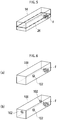
FIG. 6(a) , it would have an embodiment where a singlefire sensing sensor 102 such as a heat detector, a smoke detector and a flame detector is arranged in an appropriate position in astorage battery case 100. In this case, when a fire location F is away from the sensor, thefire sensing sensor 102 should sense the fire after the temperature in thestorage battery case 100 has risen due to fire spreading to other storage batteries. Accordingly, there is the problem that a time lag enlarges between when the fire starts and when the fire is sensed. - Thus, as shown in
FIG. 6(b) , suppose thefire sensing sensor 102 is placed at plural positions in thestorage battery case 100, regardless of the positions where a fire starts, thefire sensing sensor 102 close to the positions of the fire can sense the fire at an early stage. On the other hand, when the number offire sensing sensors 102 increases, misdetection, such as detecting temperature variations caused by the sunshine would become more possible. - The present invention which is defined by the features of claim 1 has been achieved in view of the above problems, and the aim of the present invention is to improve sensing accuracy in a fire sensing system for a railway carriage that senses a fire caused by heat-generating devices installed in a box body mounted on the railway carriage.
- Each following aspect of the present invention exemplifies the constitution of the present invention and is explained with an item separately for making the various constitutions of the present invention easily understood. The item should not limit the technical scope of the present invention, and even if any part recited in the constituent elements of each item is changed, deleted or further added with other constituent elements with reference to the best mode for carrying out the invention, those should be included in the technical scope of the present invention.
- There is provided a fire sensing system for a railway carriage that senses a fire caused by a heat-generating device installed in a box body mounted on the railway carriage, the fire sensing system comprising: a fire sensing portion that senses a fire in the heat-generating device; and a fire alarm portion to be activated when the fire sensing portion senses the fire, wherein the fire sensing portion includes: a primary feeder circuit to be electrified in a normal state; an auxiliary feeder circuit that is arranged parallel to the primary feeder circuit and that is electrified due to the fire in the heat-generating device; and a switch part that turns off the primary feeder circuit and the auxiliary feeder circuit upon the electrification of the auxiliary feeder circuit, the primary feeder circuit and the switch part are arranged in a place not directly affected by heat of the heat-generating device, and the fire alarm portion is provided with a fire alarm circuit that is turned off in a normal state and is electrified upon deactivation of the primary feeder circuit as a trigger (Claim 1).
- In the fire sensing system for the railway carriage according to claim 1, in a normal state, that is, in a condition that the heat-generating device does not cause a fire (or in a condition that the effect of heat caused by the fire in the heat-generating device does not affect the interior of the box body), the primary feeder circuit of the fire sensing portion is being electrified. During this period, the fire alarm circuit of the fire alarm portion has been turned off so that the fire alarm portion is in a non-operative condition. On the other hand, in an emergency, that is, in a condition that the heat-generating device causes a fire (or in a condition that the effect of heat caused by the fire in the heat-generating device affects the interior of the box body), the auxiliary feeder circuit arranged parallel to the primary feeder circuit will be electrified. Upon the electrification of the auxiliary feeder circuit, the switch part will turn off the primary feeder circuit and the auxiliary feeder circuit. Then, upon the deactivation of the primary feeder circuit as a trigger, the fire alarm circuit of the fire alarm portion is electrified so as to activate the fire alarm portion.
- Upon the electrification of the auxiliary feeder circuit as the initiator, the fire alarm portion will be activated while the switch part is turning off the primary feeder circuit and the auxiliary feeder circuit. Accordingly, even if the primary feeder circuit or the auxiliary feeder circuit is burnt out (lost), the fire alarm circuit is still electrified while the primary feeder circuit and the auxiliary feeder circuit are turned off due to the loss. This structure of the circuits thus allows the fire alarm portion to be activated without interruption. Further, since the primary feeder circuit and the switch part are arranged in a place not directly affected by the heat of the heat-generating device, there is no danger that the primary feeder circuit and the switch part will be burnt out before the switch part turns off the primary feeder circuit and the auxiliary feeder circuit upon the electrification of the auxiliary feeder circuit.
- There is provided the fire sensing system for the railway carriage according to claim 1 wherein the auxiliary feeder circuit is provided with a short-circuit induction wiring, the short-circuit induction wiring being structured in: a pair of parallel lead wires in which to be insulated from each other with a coating layer; being wired in the box body; and making the pair of parallel lead wires short-circuited by melting the coating layer as temperature in the box body rises (Claim 2).
- In the fire sensing system for the railway carriage according to claim 2, the auxiliary feeder circuit is provided with the short-circuit induction wiring. Since this short-circuit induction wiring will be short-circuited due to the temperature increase in the box body by the fire in the heat-generating device, the auxiliary feeder circuit will be electrified as the same with claim 1. Here, the short-circuit induction wiring may be installed in such a manner as to cover the whole inner surface of the box body. By installing the short-circuit induction wiring in this manner, it would be possible for the short-circuit induction wiring to be placed nearby a fire location regardless where the fire location is. The coating layer of the short-circuit induction wiring placed close to the fire location will be melted due to the temperature increase and be short-circuited. That is, with the short-circuit induction wiring, it would be possible to make the whole inner surface of the box body to be, namely the fire sensing portion.
- There is provided the fire sensing system for the railway carriage according to claim 1 or claim 2 wherein the switch part includes: a primary normally opened contact arranged in series with the primary feeder circuit; an auxiliary normally opened contact arranged in series with the auxiliary feeder circuit; and a first circuit breaker that is arranged in series with the auxiliary feeder circuit and that switches the primary normally opened contact and the auxiliary normally opened contact to a circuit break position upon the electrification of the auxiliary feeder circuit (Claim 3).
- In the fire sensing system for the railway carriage according to claim 3, the system is normally in the condition that the primary feeder circuit is electrified while the auxiliary feeder circuit is not electrified. Thus, in the switch part, the first circuit breaker will not switch the primary normally opened contact arranged in series with the primary feeder circuit and the auxiliary normally opened contact arranged in in series with the auxiliary feeder circuit, to a circuit break position. Accordingly, both the primary normally opened contact and the auxiliary normally opened contact will be kept in a conduction position. As explained, in a normal state the primary feeder circuit will not be turned off in the switch part and will be kept in a conduction state. On the other hand, in an emergency the auxiliary feeder circuit arranged parallel to the primary feeder circuit will be electrified, so that the primary normally opened contact and the auxiliary normally opened contact are switched to a circuit break position by the first circuit breaker arranged in series with the auxiliary feeder circuit. As a result, the primary feeder circuit and the auxiliary feeder circuit are both turned off, so that as the same with claim 1, upon the deactivation of the primary feeder circuit as a trigger, the fire alarm circuit of the fire alarm portion is electrified so as to activate the fire alarm portion.
- There is provided the fire sensing system for the railway carriage according to any one of claims 1 to 3 wherein the fire alarm circuit includes a normally closed contact to activate the fire alarm portion, and the primary feeder circuit is provided with a secondary circuit breaker that switches the normally closed contact to a connecting position when turned off (Claim 4).
- In the fire sensing system for the railway carriage according to claim 4, upon the deactivation of the primary feeder circuit, the second circuit breaker provided in the primary feeder circuit will switch the normally closed contact of the fire alarm circuit to the connecting position. Thus, the fire alarm circuit is electrified so as to activate the fire alarm portion.
- There is provided the fire sensing system for the railway carriage according to any one of claims 1 to 4 wherein the heat-generating device, which is ignitable, is a storage battery, and the box body is a storage battery case (Claim 5).
- In the fire sensing system for the railway carriage according to claim 5, the ignitable heat-generating device is the storage battery, and a fire caused by the storage battery installed in the storage battery case of the box body will be sensed through the constitution recited in claims 1 to 4 of the above.
- There is provided the fire sensing system for the railway carriage according to claim 5 wherein the storage battery case is provided with: a first compartment in which the storage battery is placed and the auxiliary feeder circuit is wired; a secondary compartment in which the switch part is arranged; and a partition that insulates an interval between the first compartment and the secondary compartment (Claim 6).
- In the fire sensing system for the railway carriage according to claim 6, due to a fire caused by the storage battery arranged in the first compartment of the storage battery case, the auxiliary feeder circuit wired in the first compartment will be electrified. On the other hand, since the switch part is arranged in the secondary compartment insulated from the first compartment with the partition, there is no danger that the switch part itself is burnt out before the primary feeder circuit and the auxiliary feeder circuit are turned off upon the electrification of the auxiliary feeder circuit.
- Since the present invention is structured as explained hereinabove, it enables to improve the sensing accuracy of a fire sensing system for a railway carriage in which to sense a fire caused by heat-generating devices installed in a box body mounted on the railway carriage.
-
-
FIG. 1 schematically illustrates the circuit diagram of a railway carriage provided with a fire sensing system for a railway carriage according to the embodiment of the present invention. -
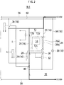
FIG. 2 is a partial extract from the circuit diagram ofFIG. 1 that indicates an electrical flow in a normal state (when a fire alarm portion is not activated). -
FIG. 3 is a partial extract from the circuit diagram ofFIG. 1 that indicates an electrical flow when a fire starts. -
FIG. 4 is a partial extract from the circuit diagram ofFIG. 1 that indicates an electrical flow when the fire alarm portion is activated. -
FIG. 5 is a three-dimensional perspective diagram that schematically indicates the condition of a storage battery when a fire starts. -
FIG. 6 (a) and FIG. 6 (b) are both three-dimensional perspective diagrams that schematically indicate the condition of the storage battery when a fire starts in conventional arts. - Hereinafter, the best modes for carrying out the present invention will be described with reference to the accompanying drawings. Here, parts that are the same as or equivalent to those of the prior arts are indicated by the same reference numerals, and the detailed description thereof will be omitted.
-
FIG. 1 schematically illustrates the circuit structure regarding the whole organization of a railway carriage to which a fire sensing system for arailway carriage 10 according to the embodiments of the present invention is adopted. In the examples shown in FIG., the railway carriage is three-car trains containing electrically controlled carriages Mc1, Mc2 and a trailer carriage T. Each of the electrically controlled carriages Mc1 and Mc2 has astorage battery case 12 mounted thereon, and astorage battery 14 is stored in thestorage battery case 12. The fire sensing system for therailway carriage 10 is each provided in the electrically controlled carriages Mc1 and Mc2 together with thestorage battery case 12. Here, each of the fire sensing systems for therailway carriage 10 in the electrically controlled carriages Mc1 and Mc2 has an identical structure. When thestorage battery case 12 is mounted on the trailer carriage T as needed, the fire sensing system for therailway carriage 10 will be also provided on the trailer carriage T. - The fire sensing system for the
railway carriage 10 is provided with afire sensing portion 16 that senses a fire caused by thestorage battery 14 and afire alarm portion 18 to be activated when thefire sensing portion 16 senses the fire caused by thestorage battery 14. Thefire sensing portion 16 includes aprimary feeder circuit 20 to be electrified in a normal state, anauxiliary feeder circuit 22 arranged parallel to theprimary feeder circuit 20 and electrified when a heat-generating device causes a fire, and aswitch part 24. - The
storage battery case 12 is divided into afirst compartment 12a in which thestorage battery 14 is mounted and theauxiliary feeder circuit 22 is wired, and asecondary compartment 12b in which theswitch part 24 is arranged. An interval between thefirst compartment 12a and thesecondary compartment 12b is insulated with apartition 12c such as a fire-protection wall that has heat-resistant properties and low thermal conductivity. The side walls, the bottom wall and the ceiling, except thepartition 12c of thestorage battery case 12, also have heat-resistant properties. Note that theprimary feeder circuit 20 is not wired in thefirst compartment 12a. Accordingly, theprimary feeder circuit 20 and theswitch part 24 are arranged in a place not directly affected by the heat generated from the fire in thestorage battery 14. As explained hereinafter, theswitch part 24 works to turn off theprimary feeder circuit 20 and theauxiliary feeder circuit 22 upon the electrification of theauxiliary feeder circuit 22. - The
auxiliary feeder circuit 22 is provided with a short-circuit induction wiring 26. This short-circuit induction wiring 26 is configured in such a manner that a pair ofparallel wires wires storage battery case 12. When thestorage battery 14 causes a fire, the interior temperature of thestorage battery case 12 rises, thereby melting the coating layer that insulates the pair ofparallel wires parallel wires circuit induction wiring 26 in a conductive condition. This will eventually make theauxiliary feeder circuit 22 conductive. - Here, it would be preferable for the short-
circuit induction wiring 26 to be installed in a wave formation to cover the whole inner surface of thestorage battery case 12. If this is not possible, at least the short-circuit induction wiring 26 should be installed at places that could be mostly affected by temperature rises of a fire caused by thestorage battery 14, for example, a ceiling surface corresponding to the area where thestorage battery 14 is installed. - The
switch part 24 includes a primary normally openedcontact 28 arranged in series with theprimary feeder circuit 20, an auxiliary normally openedcontact 30 arranged in series with theauxiliary feeder circuit 22, and afirst circuit breaker 32 arranged in series with theauxiliary feeder circuit 22. Thisfirst circuit breaker 32 works to switch the primary normally openedcontact 28 and the auxiliary normally openedcontact 30 to a circuit break position upon the electrification of theauxiliary feeder circuit 22. As an example, an electromagnetic contact is used for the primary normally openedcontact 28 and the auxiliary normally openedcontact 30 while an electromagnetic switch provided with a trip coil is used for thefirst circuit breaker 32. - The
fire alarm portion 18 is provided with afire alarm circuit 34 being turned off in a normal state and electrified upon the deactivation of theprimary feeder circuit 20 as a trigger. Thefire alarm circuit 34 includes a normally closedcontact 36 that activates thefire alarm portion 18. Further, thefire alarm circuit 34 includes afire alarm buzzer 38 installed on a driver stand, etc. as a means of a fire alarm. - Moreover, the
primary feeder circuit 20 is provided with asecondary circuit breaker 40 that turns off the electrification of the normally closedcontact 36 while theprimary feeder circuit 20 is turned off. As an example, an electromagnetic contact is used for the normally closedcontact 36 while an electromagnetic switch provided with a trip coil is used for thesecondary circuit breaker 40. - Here, regarding the
storage battery case 12 inFIG. 1 , each position between thefirst compartment 12a in which thestorage battery 14 is placed and theauxiliary feeder circuit 22 is wired and thesecond compartment 12b in which theswitch part 24 is arranged may be vertically replaced. In addition, inFIG. 1 each position between the primary normally openedcontact 28 in theswitch part 24 as well as theauxiliary feeder circuit 22 and thefirst circuit breaker 32 may be also vertically replaced. - Further, the
primary feeder circuit 20 is provided with a normally openedcontact 42. A TEMS communication circuit 44 is provided so that the train control system (TEMS) of the railway carriages will be informed of the state that theprimary feeder circuit 20 is conductive, that is, in a normal state, through the normally openedcontact 42. Still further, aTEMS communication circuit 46 is provided so that the TEMS is informed of an emergency, that is, a fire outbreak through the normally closedcontact 36 of thefire alarm circuit 34. Yet still further, there are also provided a fire-alarm forcedstoppage switch 48, which manually and forcibly stops thefire alarm circuit 34, and aTEMS communication circuit 50 which informs the TEMS of the state that the fire-alarm forcedstoppage switch 48 has been activated.Referential numerals FIG. 1 are a circuit breaker and an earthing switch, respectively. - The
primary feeder circuit 20 and theauxiliary feeder circuit 22 of the above are both connected to a power source throughlines referential numeral 60 is a line that comprises a part of thefire alarm circuit 34. - Assuming that the
storage battery 14 in thestorage battery case 12 of the electrically controlled carriage Mc1 inFIG. 1 causes a fire, the series of steps sensing the fire in the fire sensing system for therailway carriage 10 will be explained by referring toFIGS. 2 to 4 . Note that specific values inFIGS. 2 to 4 are just examples, so that the present invention should not be limited thereby. - First, in a normal state in
FIG. 2 , that is, in a condition that the storage battery (heat-generating device) 14 does not cause any fire (or in a condition that the effect of heat caused by the fire in thestorage battery 14 does not affect the interior of the storage battery case (box body) 12), theprimary feeder circuit 20 of thefire alarm portion 16 is electrified (indicated with a bold line). - In this state, since the
auxiliary feeder circuit 22 is in a non-electrified condition, in theswitch part 24, the primary normally openedcontact 28 arranged in series with theprimary feeder circuit 20 with thesecondary circuit breaker 40 and the auxiliary normally openedcontact 30 arranged in series with theauxiliary feeder circuit 22 will not be switched to a circuit break position. Instead, the primary normally openedcontact 28 and the auxiliary normally openedcontact 30 are both kept in a conduction position. In this normal state, theprimary feeder circuit 20 is not turned off by theswitch part 24, and theprimary feeder circuit 20 is thus kept in a conduction state. - Further, in the condition that the
primary feeder circuit 20 is electrified, since thesecondary circuit breaker 40 provided in theprimary feeder circuit 20 is in an electrified condition, a current I is applied to the normally closedcontact 36 of thefire alarm circuit 34 through thesecondary circuit breaker 40. Accordingly, the normally closedcontact 36 of thefire alarm circuit 34 will be kept in a circuit break position, so that thefire alarm buzzer 38 provided in thefire alarm circuit 34 is placed in a non-activating condition. - On the other hand, in case of an emergency in
FIG. 3 , that is, in the condition that thestorage battery 14 causes a fire (or in a condition that the effect of heat caused by the fire in thestorage battery 14 affects the interior of the storage battery case 12), theauxiliary feeder circuit 22 arranged parallel to theprimary feeder circuit 20 is electrified (indicated with a bold line). Specifically, the coating layer of the short-circuit induction wiring 26 in theauxiliary feeder circuit 22 will be melted by heat, so that the pair ofparallel wires auxiliary feeder circuit 22. - Upon the electrification of the
auxiliary feeder circuit 22, as shown inFIG. 4 , in theswitch part 24, the primary normally openedcontact 28 and the auxiliary normally openedcontact 30 will be switched to a circuit break position by means of thefirst circuit breaker 32 arranged in series with theauxiliary feeder circuit 22. As a result, theprimary feeder circuit 20 and theauxiliary feeder circuit 22 are both turned off. Then, upon the deactivation of theprimary feeder circuit 20 as a trigger, thefire alarm circuit 34 of thefire alarm portion 18 is electrified so as to activate thefire alarm portion 18. - Specifically, by turning off the
primary feeder circuit 20, the current I, which is applied from thesecondary circuit breaker 40 arranged in theprimary feeder circuit 20 to the normally closedcontact 36 in thefire alarm circuit 34, will be turned off. Accordingly, the normally closedcontact 36 in thefire alarm circuit 34 is switched to a connecting position, thereby electrifying the fire alarm circuit 34 (indicated with a bold line) so as to activate thefire alarm buzzer 38. In the example of FIG., upon the activation of thefire alarm buzzer 38, theTEMS communication circuit 46 is electrified through the normally closedcontact 36 in thefire alarm circuit 34. By these steps, the TEMS will be notified of an emergency, that is, a fire outbreak. - As discussed hereinabove, in the fire sensing system for the
railway carriage 10 according to the embodiments of the present invention, upon the electrification of theauxiliary feeder circuit 22 as the initiator, thefire alarm portion 18 will be activated while theprimary feeder circuit 20 and theauxiliary feeder circuit 22 are turned off with theswitch part 24. Consequently, even if theprimary feeder circuit 20 and theauxiliary feeder circuit 22 are burnt out and thus turned off, thefire alarm circuit 34 can be still electrified. This structure of the circuits will thus allow thefire alarm portion 18 to be activated without interruption. - Further, in the
storage battery case 12, due to the fire caused by thestorage battery 14 arranged in thefirst compartment 12a, the short-circuit induction wiring 26 also wired in thefirst compartment 12a will be short-circuited so as to electrify theauxiliary feeder circuit 22. Note that, by installing the short-circuit induction wiring 26 in such a manner as to cover the whole inner surface of the storage battery case 12 (schematically shown inFIG. 5 ), the short-circuit induction wiring 26 can be placed nearby a fire location F regardless of where the fire location is. Thus, the coating layer of the short-circuit induction wiring 26 where placed nearby the fire location will be melted upon temperature increase and be short-circuited. By applying the short-circuit induction wiring 26 in this manner, the whole inner surface of thestorage battery case 12 can be, in a sense, a fire sensing portion. This will enable to sense a fire at an early stage after thestorage battery 14 causes the fire. Note that, since the short-circuit induction wiring 26 will not be in a conductive condition unless short-circuited, it will not cause any misdetection, for example, detecting temperature variations caused by the sunlight, etc. - The
switch part 24 is arranged in thesecondary compartment 12b insulated from thefirst compartment 12a with a partition. That is, theswitch part 24 is arranged in a place not directly affected by the heat of a fire in thestorage battery 14. Accordingly, in theswitch part 24, upon the electrification of theauxiliary feeder circuit 22, there is no danger that theswitch part 24 itself will be burnt out before theprimary feeder circuit 20 and theauxiliary feeder circuit 22 are turned off. Further, thesecondary circuit breaker 40 of theprimary feeder circuit 20 is also arranged in a place not directly affected by the heat of a fire in thestorage battery 14. Accordingly, there is no danger that thesecondary circuit breaker 40 will be burnt out before thefire alarm buzzer 38 is activated while turning off the electrification of the normally closedcontact 36 of thefire alarm circuit 34. - According to the embodiments of the present invention, it would be possible to improve the sensing accuracy of the fire sensing system for the
railway carriage 10 in which to sense a fire in the heat-generating device installed in the box body mounted on the railway carriage. - The embodiments of the present invention have been exemplified with storage batteries installed in a storage battery case as heat-generating devices; however, it should be recognized that the present invention should be applicable for any fire sensing systems of the heat-generating devices mounted on a box body and difficult to immediately confirm a fire visibly.
- 10: Fire sensing system for railway carriage, 12: Storage battery case, 12a: First compartment, 12b: Second compartment, 12c: Partition, 14: Storage battery, 16: Fire sensing portion, 18: Fire alarm portion, 20: Primary feeder circuit, 22: Auxiliary feeder circuit, 24: Switch part, 26: Short-circuit induction wiring, 26a, 26b: Parallel wires, 28: primary normally opened contact, 30: Auxiliary normally opened contact, 32: First circuit breaker, 34: Fire alarm circuit, 36: Normally closed contact, 38: Fire alarm buzzer, 40: Second circuit breaker, 42: Normally opened contact, Mc1, Mc2: Electrically controlled carriages
Claims (6)
- A fire sensing system (10) for a railway carriage (Mc1,Mc2) that senses a fire caused by a heat-generating device (14) installed in a box body (12) mounted on the railway carriage (Mc1,Mc2), the fire sensing system (10) comprising: a fire sensing portion (16) that senses a fire in the heat-generating device (14); and a fire alarm portion (18) to be activated when the fire sensing portion (16) senses the fire, wherein the fire sensing portion (16) includes: a primary feeder circuit (20) to be electrified in a normal state; an auxiliary feeder circuit (22) that is arranged parallel to the primary feeder circuit (20) and that is electrified due to the fire in the heat-generating device; (14) and a switch part (24) that turns off the primary feeder circuit (20) and the auxiliary feeder circuit (22) upon the electrification of the auxiliary feeder circuit (22), the primary feeder circuit (20) and the switch part (24) are arranged in a place not directly affected by heat of the heat-generating device (14), and the fire alarm portion (18) is provided with a fire alarm circuit (34) that is turned off in a normal state and is electrified upon deactivation of the primary feeder circuit (20) as a trigger.
- The fire sensing system (10) for the railway carriage (Mc1,Mc2) according to claim 1 wherein the auxiliary feeder circuit (22) is provided with a short-circuit induction wiring (26), the short-circuit induction wiring (26) being structured in: a pair of parallel lead wires (26a,26b) in which to be insulated from each other with a coating layer; being wired in the box body (12); and making the pair of parallel lead wires (26a,26b) short-circuited by melting the coating layer as temperature in the box body (12) rises.
- The fire sensing system (10) for the railway carriage (Mc1,Mc2) according to claim 1 or claim 2 wherein the switch part (24) includes: a primary normally opened contact (28) arranged in series with the primary feeder circuit (20); an auxiliary normally opened contact (30) arranged in series with the auxiliary feeder circuit (22); and a first circuit breaker (32) that is arranged in series with the auxiliary feeder circuit (22) and that switches the primary normally opened contact (28) and the auxiliary normally opened contact (30) to a circuit break position upon the electrification of the auxiliary feeder circuit (22).
- The fire sensing system (10) for the railway carriage (Mc1,Mc2) according to any one of claims 1 to 3 wherein the fire alarm circuit (34) includes a normally closed contact (36) to activate the fire alarm portion (18), and the primary feeder circuit (20) is provided with a secondary circuit breaker (40) that switches the normally closed contact (36) to a connecting position when turned off.
- The fire sensing system (10) for the railway carriage (Mc1,Mc2) according to any one of claims 1 to 4 wherein the heat-generating device (14), which is ignitable, is a storage battery (14), and the box body (12) is a storage battery case (12).
- The fire sensing system (10) for the railway carriage (Mc1,Mc2) according to claim 5 wherein the storage battery case (12) is provided with: a first compartment (12a) in which the storage battery (14) is placed and the auxiliary feeder circuit (22) is wired; a secondary compartment (12b) in which the switch part (24) is arranged; and a partition (12c) that insulates an interval between the first compartment (12a) and the secondary compartment (12b).
Applications Claiming Priority (1)
| Application Number | Priority Date | Filing Date | Title |
|---|---|---|---|
| PCT/JP2016/055871 WO2017145374A1 (en) | 2016-02-26 | 2016-02-26 | Fire sensing system for railway carriage |
Publications (3)
| Publication Number | Publication Date |
|---|---|
| EP3422314A1 EP3422314A1 (en) | 2019-01-02 |
| EP3422314A4 EP3422314A4 (en) | 2020-01-29 |
| EP3422314B1 true EP3422314B1 (en) | 2021-08-11 |
Family
ID=59686000
Family Applications (1)
| Application Number | Title | Priority Date | Filing Date |
|---|---|---|---|
| EP16891531.2A Active EP3422314B1 (en) | 2016-02-26 | 2016-02-26 | Fire sensing system for railway carriage |
Country Status (5)
| Country | Link |
|---|---|
| EP (1) | EP3422314B1 (en) |
| JP (1) | JP6633179B2 (en) |
| PH (1) | PH12018550139A1 (en) |
| SG (1) | SG11201807159TA (en) |
| WO (1) | WO2017145374A1 (en) |
Families Citing this family (2)
| Publication number | Priority date | Publication date | Assignee | Title |
|---|---|---|---|---|
| CN111815880B (en) * | 2020-08-07 | 2021-04-06 | 成都惠之慧安全科技有限公司 | Electric fire and gas intelligent monitoring alarm system |
| CN112185069A (en) * | 2020-09-29 | 2021-01-05 | 浙江工业职业技术学院 | Circuit early warning system |
Family Cites Families (8)
| Publication number | Priority date | Publication date | Assignee | Title |
|---|---|---|---|---|
| JPS5737916B2 (en) * | 1972-07-14 | 1982-08-12 | ||
| JPH07109640B2 (en) * | 1992-10-19 | 1995-11-22 | 株式会社井澤電子工業 | Alarm sensor operation detection method for crime prevention and disaster prevention |
| JP3627363B2 (en) * | 1996-04-19 | 2005-03-09 | 文化シヤッター株式会社 | Opening and closing body device |
| JP3635050B2 (en) * | 2001-02-27 | 2005-03-30 | 東日本旅客鉄道株式会社 | Sediment collapse detector |
| JP2004226348A (en) * | 2003-01-27 | 2004-08-12 | Matsushita Electric Works Ltd | Thermal sensor |
| WO2005022478A1 (en) * | 2003-08-29 | 2005-03-10 | Koichi Wada | Temperature detecting device |
| KR101253308B1 (en) * | 2011-10-28 | 2013-04-10 | 현대로템 주식회사 | Fire detecting system for railway car and the railway car comprising the same |
| JP6103856B2 (en) * | 2012-08-20 | 2017-03-29 | ホーチキ株式会社 | Fire extinguishing system for electric vehicles |
-
2016
- 2016-02-26 EP EP16891531.2A patent/EP3422314B1/en active Active
- 2016-02-26 WO PCT/JP2016/055871 patent/WO2017145374A1/en not_active Ceased
- 2016-02-26 SG SG11201807159TA patent/SG11201807159TA/en unknown
- 2016-02-26 JP JP2018501543A patent/JP6633179B2/en active Active
-
2018
- 2018-08-24 PH PH12018550139A patent/PH12018550139A1/en unknown
Non-Patent Citations (1)
| Title |
|---|
| None * |
Also Published As
| Publication number | Publication date |
|---|---|
| EP3422314A1 (en) | 2019-01-02 |
| JP6633179B2 (en) | 2020-01-22 |
| SG11201807159TA (en) | 2018-09-27 |
| JPWO2017145374A1 (en) | 2019-01-31 |
| WO2017145374A1 (en) | 2017-08-31 |
| EP3422314A4 (en) | 2020-01-29 |
| PH12018550139A1 (en) | 2019-03-11 |
Similar Documents
| Publication | Publication Date | Title |
|---|---|---|
| JP6671512B2 (en) | Apparatus and method for diagnosing failure of battery relay using parallel circuit for constant power supply | |
| EP3068016A1 (en) | Wireless power supply control system that controls supplying of power according to living body detection | |
| US8947247B2 (en) | System and method for detecting and preventing cable theft in electric vehicle supply equipment | |
| US10927518B2 (en) | Third rail heater control system | |
| JP7003269B2 (en) | Storage battery unit and fire detection method for storage battery unit | |
| KR102436651B1 (en) | Switchgear (high-voltage panel, low-voltage panel, motor control panel, distribution panel) Capable of Initial Fire Extinguishing Function and Insulation Status Monitoring | |
| ES2632950T3 (en) | Device and method to prevent electric arcs | |
| EP3422314A1 (en) | Fire sensing system for railway carriage | |
| KR20200041776A (en) | Energy supply system for a consumer unit and method for supplying energy to a consumer unit | |
| CN206297510U (en) | A kind of vehicle power supply control system | |
| JP6103332B2 (en) | Battery safety device | |
| US7812734B2 (en) | Alarm system employing existing conductive aspect of copper lines as well as optional pressure switch sensor for triggering a copper theft event | |
| US10230138B2 (en) | Device and method for maintaining a battery at an operating temperature | |
| US3644912A (en) | Alarm system | |
| US10627440B2 (en) | Method and device for detecting arcs | |
| US10926653B2 (en) | Traction battery charging arrangement | |
| CN104943631A (en) | High-voltage distribution box for electric car | |
| KR20180012069A (en) | Intelligent panel board | |
| CN211097165U (en) | Fire extinguishing system applied to suspension type rail vehicle | |
| CN110758135B (en) | Charging devices and systems for rail vehicles | |
| CN215961897U (en) | Electric motor car extinguishing device | |
| CN104548424A (en) | Fire-extinguishing system of engine cabin of small car | |
| JP4190537B2 (en) | Temperature detection device | |
| US20180315987A1 (en) | Battery system for a vehicle | |
| CN110031119B (en) | Reducing cable wiring system with temperature control alarm system |
Legal Events
| Date | Code | Title | Description |
|---|---|---|---|
| STAA | Information on the status of an ep patent application or granted ep patent |
Free format text: STATUS: THE INTERNATIONAL PUBLICATION HAS BEEN MADE |
|
| PUAI | Public reference made under article 153(3) epc to a published international application that has entered the european phase |
Free format text: ORIGINAL CODE: 0009012 |
|
| STAA | Information on the status of an ep patent application or granted ep patent |
Free format text: STATUS: REQUEST FOR EXAMINATION WAS MADE |
|
| 17P | Request for examination filed |
Effective date: 20180926 |
|
| AK | Designated contracting states |
Kind code of ref document: A1 Designated state(s): AL AT BE BG CH CY CZ DE DK EE ES FI FR GB GR HR HU IE IS IT LI LT LU LV MC MK MT NL NO PL PT RO RS SE SI SK SM TR |
|
| AX | Request for extension of the european patent |
Extension state: BA ME |
|
| DAV | Request for validation of the european patent (deleted) | ||
| DAX | Request for extension of the european patent (deleted) | ||
| A4 | Supplementary search report drawn up and despatched |
Effective date: 20200108 |
|
| RIC1 | Information provided on ipc code assigned before grant |
Ipc: B61D 37/00 20060101ALI20191220BHEP Ipc: H01M 10/48 20060101ALI20191220BHEP Ipc: G08B 17/06 20060101AFI20191220BHEP Ipc: H01M 10/42 20060101ALI20191220BHEP Ipc: B61L 15/00 20060101ALI20191220BHEP |
|
| GRAP | Despatch of communication of intention to grant a patent |
Free format text: ORIGINAL CODE: EPIDOSNIGR1 |
|
| STAA | Information on the status of an ep patent application or granted ep patent |
Free format text: STATUS: GRANT OF PATENT IS INTENDED |
|
| INTG | Intention to grant announced |
Effective date: 20201009 |
|
| GRAJ | Information related to disapproval of communication of intention to grant by the applicant or resumption of examination proceedings by the epo deleted |
Free format text: ORIGINAL CODE: EPIDOSDIGR1 |
|
| STAA | Information on the status of an ep patent application or granted ep patent |
Free format text: STATUS: REQUEST FOR EXAMINATION WAS MADE |
|
| GRAS | Grant fee paid |
Free format text: ORIGINAL CODE: EPIDOSNIGR3 |
|
| STAA | Information on the status of an ep patent application or granted ep patent |
Free format text: STATUS: GRANT OF PATENT IS INTENDED |
|
| GRAP | Despatch of communication of intention to grant a patent |
Free format text: ORIGINAL CODE: EPIDOSNIGR1 |
|
| INTC | Intention to grant announced (deleted) | ||
| INTG | Intention to grant announced |
Effective date: 20210302 |
|
| GRAA | (expected) grant |
Free format text: ORIGINAL CODE: 0009210 |
|
| STAA | Information on the status of an ep patent application or granted ep patent |
Free format text: STATUS: THE PATENT HAS BEEN GRANTED |
|
| AK | Designated contracting states |
Kind code of ref document: B1 Designated state(s): AL AT BE BG CH CY CZ DE DK EE ES FI FR GB GR HR HU IE IS IT LI LT LU LV MC MK MT NL NO PL PT RO RS SE SI SK SM TR |
|
| REG | Reference to a national code |
Ref country code: CH Ref legal event code: EP |
|
| REG | Reference to a national code |
Ref country code: DE Ref legal event code: R096 Ref document number: 602016062211 Country of ref document: DE |
|
| REG | Reference to a national code |
Ref country code: IE Ref legal event code: FG4D Ref country code: AT Ref legal event code: REF Ref document number: 1420182 Country of ref document: AT Kind code of ref document: T Effective date: 20210915 |
|
| REG | Reference to a national code |
Ref country code: LT Ref legal event code: MG9D |
|
| REG | Reference to a national code |
Ref country code: NL Ref legal event code: MP Effective date: 20210811 |
|
| REG | Reference to a national code |
Ref country code: AT Ref legal event code: MK05 Ref document number: 1420182 Country of ref document: AT Kind code of ref document: T Effective date: 20210811 |
|
| PG25 | Lapsed in a contracting state [announced via postgrant information from national office to epo] |
Ref country code: SE Free format text: LAPSE BECAUSE OF FAILURE TO SUBMIT A TRANSLATION OF THE DESCRIPTION OR TO PAY THE FEE WITHIN THE PRESCRIBED TIME-LIMIT Effective date: 20210811 Ref country code: RS Free format text: LAPSE BECAUSE OF FAILURE TO SUBMIT A TRANSLATION OF THE DESCRIPTION OR TO PAY THE FEE WITHIN THE PRESCRIBED TIME-LIMIT Effective date: 20210811 Ref country code: LT Free format text: LAPSE BECAUSE OF FAILURE TO SUBMIT A TRANSLATION OF THE DESCRIPTION OR TO PAY THE FEE WITHIN THE PRESCRIBED TIME-LIMIT Effective date: 20210811 Ref country code: AT Free format text: LAPSE BECAUSE OF FAILURE TO SUBMIT A TRANSLATION OF THE DESCRIPTION OR TO PAY THE FEE WITHIN THE PRESCRIBED TIME-LIMIT Effective date: 20210811 Ref country code: BG Free format text: LAPSE BECAUSE OF FAILURE TO SUBMIT A TRANSLATION OF THE DESCRIPTION OR TO PAY THE FEE WITHIN THE PRESCRIBED TIME-LIMIT Effective date: 20211111 Ref country code: NO Free format text: LAPSE BECAUSE OF FAILURE TO SUBMIT A TRANSLATION OF THE DESCRIPTION OR TO PAY THE FEE WITHIN THE PRESCRIBED TIME-LIMIT Effective date: 20211111 Ref country code: PT Free format text: LAPSE BECAUSE OF FAILURE TO SUBMIT A TRANSLATION OF THE DESCRIPTION OR TO PAY THE FEE WITHIN THE PRESCRIBED TIME-LIMIT Effective date: 20211213 Ref country code: FI Free format text: LAPSE BECAUSE OF FAILURE TO SUBMIT A TRANSLATION OF THE DESCRIPTION OR TO PAY THE FEE WITHIN THE PRESCRIBED TIME-LIMIT Effective date: 20210811 Ref country code: ES Free format text: LAPSE BECAUSE OF FAILURE TO SUBMIT A TRANSLATION OF THE DESCRIPTION OR TO PAY THE FEE WITHIN THE PRESCRIBED TIME-LIMIT Effective date: 20210811 Ref country code: HR Free format text: LAPSE BECAUSE OF FAILURE TO SUBMIT A TRANSLATION OF THE DESCRIPTION OR TO PAY THE FEE WITHIN THE PRESCRIBED TIME-LIMIT Effective date: 20210811 |
|
| PG25 | Lapsed in a contracting state [announced via postgrant information from national office to epo] |
Ref country code: PL Free format text: LAPSE BECAUSE OF FAILURE TO SUBMIT A TRANSLATION OF THE DESCRIPTION OR TO PAY THE FEE WITHIN THE PRESCRIBED TIME-LIMIT Effective date: 20210811 Ref country code: LV Free format text: LAPSE BECAUSE OF FAILURE TO SUBMIT A TRANSLATION OF THE DESCRIPTION OR TO PAY THE FEE WITHIN THE PRESCRIBED TIME-LIMIT Effective date: 20210811 Ref country code: GR Free format text: LAPSE BECAUSE OF FAILURE TO SUBMIT A TRANSLATION OF THE DESCRIPTION OR TO PAY THE FEE WITHIN THE PRESCRIBED TIME-LIMIT Effective date: 20211112 |
|
| PG25 | Lapsed in a contracting state [announced via postgrant information from national office to epo] |
Ref country code: NL Free format text: LAPSE BECAUSE OF FAILURE TO SUBMIT A TRANSLATION OF THE DESCRIPTION OR TO PAY THE FEE WITHIN THE PRESCRIBED TIME-LIMIT Effective date: 20210811 |
|
| PG25 | Lapsed in a contracting state [announced via postgrant information from national office to epo] |
Ref country code: DK Free format text: LAPSE BECAUSE OF FAILURE TO SUBMIT A TRANSLATION OF THE DESCRIPTION OR TO PAY THE FEE WITHIN THE PRESCRIBED TIME-LIMIT Effective date: 20210811 |
|
| REG | Reference to a national code |
Ref country code: DE Ref legal event code: R097 Ref document number: 602016062211 Country of ref document: DE |
|
| PG25 | Lapsed in a contracting state [announced via postgrant information from national office to epo] |
Ref country code: SM Free format text: LAPSE BECAUSE OF FAILURE TO SUBMIT A TRANSLATION OF THE DESCRIPTION OR TO PAY THE FEE WITHIN THE PRESCRIBED TIME-LIMIT Effective date: 20210811 Ref country code: SK Free format text: LAPSE BECAUSE OF FAILURE TO SUBMIT A TRANSLATION OF THE DESCRIPTION OR TO PAY THE FEE WITHIN THE PRESCRIBED TIME-LIMIT Effective date: 20210811 Ref country code: RO Free format text: LAPSE BECAUSE OF FAILURE TO SUBMIT A TRANSLATION OF THE DESCRIPTION OR TO PAY THE FEE WITHIN THE PRESCRIBED TIME-LIMIT Effective date: 20210811 Ref country code: EE Free format text: LAPSE BECAUSE OF FAILURE TO SUBMIT A TRANSLATION OF THE DESCRIPTION OR TO PAY THE FEE WITHIN THE PRESCRIBED TIME-LIMIT Effective date: 20210811 Ref country code: CZ Free format text: LAPSE BECAUSE OF FAILURE TO SUBMIT A TRANSLATION OF THE DESCRIPTION OR TO PAY THE FEE WITHIN THE PRESCRIBED TIME-LIMIT Effective date: 20210811 Ref country code: AL Free format text: LAPSE BECAUSE OF FAILURE TO SUBMIT A TRANSLATION OF THE DESCRIPTION OR TO PAY THE FEE WITHIN THE PRESCRIBED TIME-LIMIT Effective date: 20210811 |
|
| PLBE | No opposition filed within time limit |
Free format text: ORIGINAL CODE: 0009261 |
|
| STAA | Information on the status of an ep patent application or granted ep patent |
Free format text: STATUS: NO OPPOSITION FILED WITHIN TIME LIMIT |
|
| 26N | No opposition filed |
Effective date: 20220512 |
|
| PG25 | Lapsed in a contracting state [announced via postgrant information from national office to epo] |
Ref country code: IT Free format text: LAPSE BECAUSE OF FAILURE TO SUBMIT A TRANSLATION OF THE DESCRIPTION OR TO PAY THE FEE WITHIN THE PRESCRIBED TIME-LIMIT Effective date: 20210811 |
|
| PG25 | Lapsed in a contracting state [announced via postgrant information from national office to epo] |
Ref country code: SI Free format text: LAPSE BECAUSE OF FAILURE TO SUBMIT A TRANSLATION OF THE DESCRIPTION OR TO PAY THE FEE WITHIN THE PRESCRIBED TIME-LIMIT Effective date: 20210811 |
|
| REG | Reference to a national code |
Ref country code: DE Ref legal event code: R119 Ref document number: 602016062211 Country of ref document: DE |
|
| PG25 | Lapsed in a contracting state [announced via postgrant information from national office to epo] |
Ref country code: MC Free format text: LAPSE BECAUSE OF FAILURE TO SUBMIT A TRANSLATION OF THE DESCRIPTION OR TO PAY THE FEE WITHIN THE PRESCRIBED TIME-LIMIT Effective date: 20210811 |
|
| REG | Reference to a national code |
Ref country code: CH Ref legal event code: PL |
|
| REG | Reference to a national code |
Ref country code: BE Ref legal event code: MM Effective date: 20220228 |
|
| PG25 | Lapsed in a contracting state [announced via postgrant information from national office to epo] |
Ref country code: LU Free format text: LAPSE BECAUSE OF NON-PAYMENT OF DUE FEES Effective date: 20220226 |
|
| PG25 | Lapsed in a contracting state [announced via postgrant information from national office to epo] |
Ref country code: FR Free format text: LAPSE BECAUSE OF NON-PAYMENT OF DUE FEES Effective date: 20220228 |
|
| PG25 | Lapsed in a contracting state [announced via postgrant information from national office to epo] |
Ref country code: LI Free format text: LAPSE BECAUSE OF NON-PAYMENT OF DUE FEES Effective date: 20220228 Ref country code: DE Free format text: LAPSE BECAUSE OF NON-PAYMENT OF DUE FEES Effective date: 20220901 Ref country code: CH Free format text: LAPSE BECAUSE OF NON-PAYMENT OF DUE FEES Effective date: 20220228 |
|
| PG25 | Lapsed in a contracting state [announced via postgrant information from national office to epo] |
Ref country code: BE Free format text: LAPSE BECAUSE OF NON-PAYMENT OF DUE FEES Effective date: 20220228 |
|
| PG25 | Lapsed in a contracting state [announced via postgrant information from national office to epo] |
Ref country code: HU Free format text: LAPSE BECAUSE OF FAILURE TO SUBMIT A TRANSLATION OF THE DESCRIPTION OR TO PAY THE FEE WITHIN THE PRESCRIBED TIME-LIMIT; INVALID AB INITIO Effective date: 20160226 |
|
| PG25 | Lapsed in a contracting state [announced via postgrant information from national office to epo] |
Ref country code: MK Free format text: LAPSE BECAUSE OF FAILURE TO SUBMIT A TRANSLATION OF THE DESCRIPTION OR TO PAY THE FEE WITHIN THE PRESCRIBED TIME-LIMIT Effective date: 20210811 Ref country code: CY Free format text: LAPSE BECAUSE OF FAILURE TO SUBMIT A TRANSLATION OF THE DESCRIPTION OR TO PAY THE FEE WITHIN THE PRESCRIBED TIME-LIMIT Effective date: 20210811 |
|
| PG25 | Lapsed in a contracting state [announced via postgrant information from national office to epo] |
Ref country code: MT Free format text: LAPSE BECAUSE OF FAILURE TO SUBMIT A TRANSLATION OF THE DESCRIPTION OR TO PAY THE FEE WITHIN THE PRESCRIBED TIME-LIMIT Effective date: 20210811 |
|
| PG25 | Lapsed in a contracting state [announced via postgrant information from national office to epo] |
Ref country code: TR Free format text: LAPSE BECAUSE OF FAILURE TO SUBMIT A TRANSLATION OF THE DESCRIPTION OR TO PAY THE FEE WITHIN THE PRESCRIBED TIME-LIMIT Effective date: 20210811 |
|
| PGFP | Annual fee paid to national office [announced via postgrant information from national office to epo] |
Ref country code: GB Payment date: 20260219 Year of fee payment: 11 |
|
| PGFP | Annual fee paid to national office [announced via postgrant information from national office to epo] |
Ref country code: IE Payment date: 20260218 Year of fee payment: 11 |