EP3422079A1 - Head-up display device - Google Patents
Head-up display device Download PDFInfo
- Publication number
- EP3422079A1 EP3422079A1 EP17756300.4A EP17756300A EP3422079A1 EP 3422079 A1 EP3422079 A1 EP 3422079A1 EP 17756300 A EP17756300 A EP 17756300A EP 3422079 A1 EP3422079 A1 EP 3422079A1
- Authority
- EP
- European Patent Office
- Prior art keywords
- head
- display device
- moving part
- sliding surface
- display
- Prior art date
- Legal status (The legal status is an assumption and is not a legal conclusion. Google has not performed a legal analysis and makes no representation as to the accuracy of the status listed.)
- Withdrawn
Links
Images


Classifications
-
- H—ELECTRICITY
- H04—ELECTRIC COMMUNICATION TECHNIQUE
- H04N—PICTORIAL COMMUNICATION, e.g. TELEVISION
- H04N13/00—Stereoscopic video systems; Multi-view video systems; Details thereof
- H04N13/30—Image reproducers
-
- B—PERFORMING OPERATIONS; TRANSPORTING
- B60—VEHICLES IN GENERAL
- B60K—ARRANGEMENT OR MOUNTING OF PROPULSION UNITS OR OF TRANSMISSIONS IN VEHICLES; ARRANGEMENT OR MOUNTING OF PLURAL DIVERSE PRIME-MOVERS IN VEHICLES; AUXILIARY DRIVES FOR VEHICLES; INSTRUMENTATION OR DASHBOARDS FOR VEHICLES; ARRANGEMENTS IN CONNECTION WITH COOLING, AIR INTAKE, GAS EXHAUST OR FUEL SUPPLY OF PROPULSION UNITS IN VEHICLES
- B60K35/00—Instruments specially adapted for vehicles; Arrangement of instruments in or on vehicles
- B60K35/20—Output arrangements, i.e. from vehicle to user, associated with vehicle functions or specially adapted therefor
- B60K35/21—Output arrangements, i.e. from vehicle to user, associated with vehicle functions or specially adapted therefor using visual output, e.g. blinking lights or matrix displays
- B60K35/23—Head-up displays [HUD]
-
- B—PERFORMING OPERATIONS; TRANSPORTING
- B60—VEHICLES IN GENERAL
- B60K—ARRANGEMENT OR MOUNTING OF PROPULSION UNITS OR OF TRANSMISSIONS IN VEHICLES; ARRANGEMENT OR MOUNTING OF PLURAL DIVERSE PRIME-MOVERS IN VEHICLES; AUXILIARY DRIVES FOR VEHICLES; INSTRUMENTATION OR DASHBOARDS FOR VEHICLES; ARRANGEMENTS IN CONNECTION WITH COOLING, AIR INTAKE, GAS EXHAUST OR FUEL SUPPLY OF PROPULSION UNITS IN VEHICLES
- B60K35/00—Instruments specially adapted for vehicles; Arrangement of instruments in or on vehicles
- B60K35/50—Instruments characterised by their means of attachment to or integration in the vehicle
- B60K35/53—Movable instruments, e.g. slidable
-
- G—PHYSICS
- G02—OPTICS
- G02B—OPTICAL ELEMENTS, SYSTEMS OR APPARATUS
- G02B27/00—Optical systems or apparatus not provided for by any of the groups G02B1/00 - G02B26/00, G02B30/00
- G02B27/01—Head-up displays
-
- G—PHYSICS
- G02—OPTICS
- G02B—OPTICAL ELEMENTS, SYSTEMS OR APPARATUS
- G02B27/00—Optical systems or apparatus not provided for by any of the groups G02B1/00 - G02B26/00, G02B30/00
- G02B27/01—Head-up displays
- G02B27/0101—Head-up displays characterised by optical features
-
- G—PHYSICS
- G02—OPTICS
- G02B—OPTICAL ELEMENTS, SYSTEMS OR APPARATUS
- G02B27/00—Optical systems or apparatus not provided for by any of the groups G02B1/00 - G02B26/00, G02B30/00
- G02B27/01—Head-up displays
- G02B27/0149—Head-up displays characterised by mechanical features
-
- G—PHYSICS
- G02—OPTICS
- G02B—OPTICAL ELEMENTS, SYSTEMS OR APPARATUS
- G02B27/00—Optical systems or apparatus not provided for by any of the groups G02B1/00 - G02B26/00, G02B30/00
- G02B27/01—Head-up displays
- G02B27/0179—Display position adjusting means not related to the information to be displayed
-
- B—PERFORMING OPERATIONS; TRANSPORTING
- B60—VEHICLES IN GENERAL
- B60K—ARRANGEMENT OR MOUNTING OF PROPULSION UNITS OR OF TRANSMISSIONS IN VEHICLES; ARRANGEMENT OR MOUNTING OF PLURAL DIVERSE PRIME-MOVERS IN VEHICLES; AUXILIARY DRIVES FOR VEHICLES; INSTRUMENTATION OR DASHBOARDS FOR VEHICLES; ARRANGEMENTS IN CONNECTION WITH COOLING, AIR INTAKE, GAS EXHAUST OR FUEL SUPPLY OF PROPULSION UNITS IN VEHICLES
- B60K2360/00—Indexing scheme associated with groups B60K35/00 or B60K37/00 relating to details of instruments or dashboards
- B60K2360/20—Optical features of instruments
- B60K2360/33—Illumination features
- B60K2360/334—Projection means
-
- G—PHYSICS
- G02—OPTICS
- G02B—OPTICAL ELEMENTS, SYSTEMS OR APPARATUS
- G02B27/00—Optical systems or apparatus not provided for by any of the groups G02B1/00 - G02B26/00, G02B30/00
- G02B27/01—Head-up displays
- G02B27/0149—Head-up displays characterised by mechanical features
- G02B2027/0154—Head-up displays characterised by mechanical features with movable elements
-
- G—PHYSICS
- G02—OPTICS
- G02B—OPTICAL ELEMENTS, SYSTEMS OR APPARATUS
- G02B27/00—Optical systems or apparatus not provided for by any of the groups G02B1/00 - G02B26/00, G02B30/00
- G02B27/01—Head-up displays
- G02B27/0149—Head-up displays characterised by mechanical features
- G02B2027/0154—Head-up displays characterised by mechanical features with movable elements
- G02B2027/0159—Head-up displays characterised by mechanical features with movable elements with mechanical means other than scaning means for positioning the whole image
-
- G—PHYSICS
- G02—OPTICS
- G02B—OPTICAL ELEMENTS, SYSTEMS OR APPARATUS
- G02B27/00—Optical systems or apparatus not provided for by any of the groups G02B1/00 - G02B26/00, G02B30/00
- G02B27/01—Head-up displays
- G02B27/0149—Head-up displays characterised by mechanical features
- G02B2027/0161—Head-up displays characterised by mechanical features characterised by the relative positioning of the constitutive elements
- G02B2027/0163—Electric or electronic control thereof
Definitions
- the present invention relates to a head-up display device including a moving part.
- Patent Literature 1 describes, as a conventional head-up display device including a moving part, a device configured to rotate a reflecting mirror that reflects display light emitted by a display.
- Patent Literature 2 describes a head-up display device configured such that a combiner for receiving display light emitted by a display and displaying a virtual image is moved into the head-up display device and that after the combiner is moved, a cover member for preventing the entry of a foreign object into the head-up display device is moved and closed.
- a head-up display device includes: a display that emits display light; a moving part on which a first sliding surface is formed; and a support member on which a second sliding surface that makes contact with the first sliding surface is formed, the support member supporting the moving part so that the moving part is movable.
- the head-up display device is configured to display vehicle information as a virtual image from the display light. Recesses and protrusions that extend along a trajectory in which the moving part moves are formed on the first sliding surface and/or the second sliding surface.
- the recesses and protrusions may be formed periodically at predetermined intervals in a direction perpendicular to the trajectory in which the moving part moves.
- the recesses and protrusions may be configured such that an arithmetic average roughness in the direction perpendicular to the trajectory in which the moving part moves is below 10 ⁇ m.
- the recesses and protrusions may be cutting marks or grinding marks.
- a resin material may be injection-molded into a mold on which the cutting marks or the grinding marks are formed, and therefore the recesses and protrusions are formed.
- a head-up display device H1 according to a first embodiment of the present invention and a head-up display device H2 according to a second embodiment of the present invention will be described below with reference to the accompanying drawings.
- the right and left side indicates the right and left side based on an occupant in a vehicle and corresponds to an x-axis in the accompanying drawings.
- the front and back side indicates the front and back side based on the occupant in the vehicle and corresponds to a z-axis in the accompanying drawings.
- the upper and lower side indicates the upper and lower side based on the occupant in the vehicle and corresponds to a y-axis in the accompanying drawings.
- the head-up display device H1 is installed in the vehicle and is configured to project display light L on a windshield of the vehicle and display a virtual image forward of the windshield. For example, vehicle information such as the running speed or the engine speed of the vehicle, or a route guidance map is indicated as the virtual image.
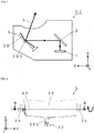
- the head-up display device H1 includes a display 1 configure to emit the display light L and reflecting mirrors 2, 3 on which the display light L is reflected.
- the display 1 is a liquid crystal display configured to emit the display light L that indicates the vehicle information.
- the reflecting mirror 2 is a reflecting mirror obtained by forming, on a surface of a resin member such as polycarbonate (PC), a flat reflecting surface on which metal such as aluminum is vapor-deposited.
- the reflecting mirror 2 reflects the display light L emitted from the display 1 toward the reflecting mirror 3.
- the reflecting mirror 2 is configured so as to reflex the display light L in a housing of the head-up display device. Accordingly, the light path length of the display light L from the display 1 to the windshield elongates and therefore the virtual image can be displayed further forward of the windshield.
- the reflecting mirror 3 is a reflecting mirror obtained by forming, on a surface of a base member 30 of a resin member such as polycarbonate, a reflecting surface of a concave surface on which metal such as aluminum is vapor-deposited.
- the reflecting mirror 3 reflects the display light L reflected by the reflecting mirror 2 toward the windshield. Since the reflecting surface of the concave surface is formed on the reflecting mirror 3, an effect that expands the display light L is achieved. As a result, even if the display 1 is configured as a relatively small and inexpensive display, the large virtual image can be displayed on the windshield.
- the reflecting mirror 3 is a moving part configured to be rotatable about a rotation axis AX.
- the reflecting mirror 3 is rotated about the rotation axis AX extending in the x-axis direction and thereby the position in which the virtual image is displayed can be moved in the up to down direction (the y-axis direction) of the windshield in accordance with the eye level of the occupant.
- the reflecting mirror 3 mainly includes the base member 30 including the reflecting surface, a support member 31 supporting the base member 30, and a drive member 32 configured to rotate the base member 30 supported by the support member 31.
- the base member 30 includes a cylindrical shaft portion 300 supported by the support member 31 and an operation portion 301 configured to transmit driving force of the drive member 31 to the base member 30.
- the base member 30, the shaft portion 300, and the operation portion 301 are integrally formed by injection molding with a resin material.
- the support member 31 is molded by injection molding with a resin material.
- the shaft portion 300 of the base member 30 and the support member 31 supporting the shaft portion 300 include sliding surfaces 300a, 31a that make contact with each other.
- Tool marks (recesses and protrusions) TM1, TM2 as marks generated as a result of cutting or grinding an injection molding mold are respectively formed on the sliding surfaces 300a, 31a.
- the tool marks TM1, TM2 are fine recesses and protrusions; however, if the tool marks TM1, TM2 do not extend along a trajectory in which the reflecting mirror 3 moves, sliding performance may deteriorate during the movement of the reflecting mirror 3 and thus abnormal noise may be generated during the movement of the reflecting mirror 3.
- the tool mark TM1 on the sliding surface (a first sliding surface) 300a of the shaft portion 300 includes the recesses and protrusions that linearly extend in a rotation direction having an axis as the rotation axis AX of the reflecting mirror 3. Also, the tool mark TM1 is formed periodically at predetermined intervals in a direction perpendicular to the rotation direction of the reflecting mirror 3. An arithmetic average roughness of the tool mark TM1 in the direction perpendicular to the rotation direction is defined as a value below 10 ⁇ m.
- the tool mark TM2 on the sliding surface (a second sliding surface) 31a of the support member 31 includes the recesses and protrusions that extend in the rotation direction having the axis as the rotation axis AX of the reflecting mirror 3. Also, the tool mark TM2 is formed periodically at predetermined intervals in the direction perpendicular to the rotation direction of the reflecting mirror 3. An arithmetic average roughness of the tool mark TM1 in the direction perpendicular to the rotation direction is defined as a value below 10 ⁇ m.
- the drive member 32 includes, for example, a motor rotating and a ball screw configured to convert a rotational movement of the motor into a parallel movement.
- the drive member 32 moves the operation portion 301 parallel in the z-axis direction perpendicular to the rotation axis AX and thereby the reflecting mirror 3 is rotated about the rotation axis AX.
- the reflecting mirror 3 includes a pressing member configured to be pressed in a direction toward a contact surface of the sliding surface 300a of the shaft portion 300 with the sliding surface 31a of the support member 31.
- the pressing member (not shown) is, for example, a plate spring, and looseness between the shaft portion 300 and the support member 31 is eliminated by the pressing member and therefore the occurrence of abnormal noise due to vibration can be inhibited.
- the head-up display device H1 includes the display 1 configured to emit the display light L, the moving part 30 on which the first sliding surface 300a is formed, and the support member 31 on which the second sliding surface 31a that makes contact with the first sliding surface 300a is formed and which supports the moving part 30 so that the moving part 30 is rotatable.
- the head-up display device H1 is configured to display the vehicle information as the virtual image from the display light L.
- the recesses and protrusions TM1, TM2 linearly extending along the trajectory in which the moving part 30 moves are formed on the first sliding surface 300a and/or the second sliding surface 31.
- the head-up display device H2 includes the display 1 configured to emit the display light L, a combiner 4 configured to receive the display light L and display a virtual image, and a cover member 5 as a cover of a housing of the head-up display H2.
- the combiner 4 is a half mirror obtained by forming a semi-transmissive reflecting layer on a primary surface (for receiving the display light L) of transmissive resin such as polymethyl methacrylate (PMMA) resin formed in a plate-shape having a curved surface.
- the combiner 4 including a cylindrical shaft portion 400 is configured to be rotatable around the shaft portion 400 as a rotation axis.
- the combiner 4 is configured to be movable between two conditions where, as shown in Fig. 6 , the combiner 4 is in a stand-up position and protruded outward of the housing of the head-up display device H2 and where, as shown in Fig. 7 and Fig. 8 , the combiner 4 is in a fallen down position and stored in the housing of the head-up display device H2.
- a sliding surface of the shaft portion 400 of the combiner 4 and a sliding surface of a support portion (not shown) supporting the shaft portion 400 are configured to make contact with each other and are formed, in the same way as the tool marks TM1, TM2 formed on the shaft portion 300 and the support portion 31 of the reflecting mirror 3 in the first embodiment, as recesses and protrusions that extend along a trajectory in which the combiner 4 moves.
- the cover member 5 moves to a position in which the cover of the housing is open.
- the cover member 5 moves to a position in which the cover of the housing is closed. That is, the moving part according to the present invention is not limited to the reflecting mirror and can be applied to the combiner.
- a sliding surface of a shaft portion 500 of the cover member 5 and a sliding surface of a support portion 51 supporting the shaft portion 500 are configured to make contact with each other and are formed, in the same way as the tool marks TM1, TM2 formed on the shaft portion 300 and the support portion 31 of the reflecting mirror 3 in the first embodiment, as recesses and protrusions that extend along a trajectory in which the cover member 5 moves. That is, the movement according to the present invention is not limited to a rotation and may include a parallel movement.
- the configuration of the head-up display device H1 according to the first embodiment of the present invention and the configuration of the head-up display device H2 according to the second embodiment of the present invention have been described.
- the present invention is not limited by the foregoing embodiments (including the contents of the drawings). Changes (including the elimination of elements) can be made to the foregoing embodiments within the scope of the present invention.
- the moving parts in the foregoing embodiments are configured as members that are injection-molded with a resin material, and the tool marks TM1, TM2 are formed on the moving parts by marks generated as a result of cutting or grinding an injection molding mold; however, the moving parts are not limited to such a configuration.
- a moving part and a support member supporting the moving member may be made of metal, and the metal may be cut or grinded to form tool marks.
- the present invention is applicable to a head-up display device installed in a vehicle.
Landscapes
- Physics & Mathematics (AREA)
- Engineering & Computer Science (AREA)
- General Physics & Mathematics (AREA)
- Optics & Photonics (AREA)
- Chemical & Material Sciences (AREA)
- Combustion & Propulsion (AREA)
- Transportation (AREA)
- Mechanical Engineering (AREA)
- Multimedia (AREA)
- Signal Processing (AREA)
- Instrument Panels (AREA)
Abstract
Description
- The present invention relates to a head-up display device including a moving part.
-
Patent Literature 1 describes, as a conventional head-up display device including a moving part, a device configured to rotate a reflecting mirror that reflects display light emitted by a display. - Also,
Patent Literature 2 describes a head-up display device configured such that a combiner for receiving display light emitted by a display and displaying a virtual image is moved into the head-up display device and that after the combiner is moved, a cover member for preventing the entry of a foreign object into the head-up display device is moved and closed. -
- Patent Literature 1: Japanese Unexamined Patent Application Publication No.
2010-230157 - Patent Literature 2: Japanese Unexamined Patent Application Publication No.
2014-226961 - However, there has been room for improvement on sliding performance of a sliding surface between each of these moving parts (the reflecting mirror, the combiner, and the cover member) and each of support members supporting the corresponding moving parts.
- A head-up display device according to the present invention includes: a display that emits display light; a moving part on which a first sliding surface is formed; and a support member on which a second sliding surface that makes contact with the first sliding surface is formed, the support member supporting the moving part so that the moving part is movable. The head-up display device is configured to display vehicle information as a virtual image from the display light. Recesses and protrusions that extend along a trajectory in which the moving part moves are formed on the first sliding surface and/or the second sliding surface.
- In the head-up display device according to the present invention, the recesses and protrusions may be formed periodically at predetermined intervals in a direction perpendicular to the trajectory in which the moving part moves.
- In the head-up display device according to the present invention, the recesses and protrusions may be configured such that an arithmetic average roughness in the direction perpendicular to the trajectory in which the moving part moves is below 10 µm.
- In the head-up display device according to the present invention, the recesses and protrusions may be cutting marks or grinding marks.
- In the head-up display device according to the present invention, a resin material may be injection-molded into a mold on which the cutting marks or the grinding marks are formed, and therefore the recesses and protrusions are formed.
- Sliding performance between a moving part and a support member supporting the moving part is improved.
-
- [
Fig. 1] Fig. 1 is a schematic configuration diagram of a head-up display device H1 according to a first embodiment of the present invention. - [
Fig. 2] Fig. 2 is a front view illustrating the configuration of a reflectingmirror 3 of the head-up display device H1. - [
Fig. 3] Fig. 3 is a cross-sectional view taken along the line A-A, illustrating the support structure of the reflectingmirror 3 of the head-up display device H1. - [
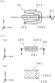
Fig. 4] Fig. 4 is a top view illustrating a first sliding surface 300a of the reflectingmirror 3 of the head-up display device H1 and a cross-sectional view taken along the line B-B. (a) illustrates the top view and (b) illustrates the cross-sectional view taken along the line B-B. - [
Fig. 5] Fig. 5 is a top view illustrating a second sliding surface 31a of the reflectingmirror 3 and a cross-sectional view taken along the line C-C. (a) illustrates the top view and (b) illustrates the cross-sectional view taken along the line B-B. - [
Fig. 6] Fig. 6 is a perspective view and a schematic configuration diagram illustrating the configuration of a head-up display device H2 according to a second embodiment of the present invention. (a) illustrates the perspective view and (b) illustrates the schematic configuration diagram. - [
Fig. 7] Fig. 7 is a perspective view and and a schematic configuration diagram illustrating the configuration of the head-up display device H2. (a) illustrates the perspective view and (b) illustrates the schematic configuration diagram. - [
Fig. 8] Fig. 8 is a perspective view and and a schematic configuration diagram illustrating the configuration of the head-up display device H2. (a) illustrates the perspective view and (b) illustrates the schematic configuration diagram. - A head-up display device H1 according to a first embodiment of the present invention and a head-up display device H2 according to a second embodiment of the present invention will be described below with reference to the accompanying drawings. In addition, in the descriptions, the right and left side indicates the right and left side based on an occupant in a vehicle and corresponds to an x-axis in the accompanying drawings. The front and back side indicates the front and back side based on the occupant in the vehicle and corresponds to a z-axis in the accompanying drawings. The upper and lower side indicates the upper and lower side based on the occupant in the vehicle and corresponds to a y-axis in the accompanying drawings.
- The head-up display device H1 is installed in the vehicle and is configured to project display light L on a windshield of the vehicle and display a virtual image forward of the windshield. For example, vehicle information such as the running speed or the engine speed of the vehicle, or a route guidance map is indicated as the virtual image.
- As shown in
Fig. 1 , the head-up display device H1 includes adisplay 1 configure to emit the display light L and reflectingmirrors - The
display 1 is a liquid crystal display configured to emit the display light L that indicates the vehicle information. - The reflecting
mirror 2 is a reflecting mirror obtained by forming, on a surface of a resin member such as polycarbonate (PC), a flat reflecting surface on which metal such as aluminum is vapor-deposited. The reflectingmirror 2 reflects the display light L emitted from thedisplay 1 toward the reflectingmirror 3. The reflectingmirror 2 is configured so as to reflex the display light L in a housing of the head-up display device. Accordingly, the light path length of the display light L from thedisplay 1 to the windshield elongates and therefore the virtual image can be displayed further forward of the windshield. - The reflecting
mirror 3 is a reflecting mirror obtained by forming, on a surface of abase member 30 of a resin member such as polycarbonate, a reflecting surface of a concave surface on which metal such as aluminum is vapor-deposited. The reflectingmirror 3 reflects the display light L reflected by thereflecting mirror 2 toward the windshield. Since the reflecting surface of the concave surface is formed on the reflectingmirror 3, an effect that expands the display light L is achieved. As a result, even if thedisplay 1 is configured as a relatively small and inexpensive display, the large virtual image can be displayed on the windshield. - The reflecting
mirror 3 is a moving part configured to be rotatable about a rotation axis AX. The reflectingmirror 3 is rotated about the rotation axis AX extending in the x-axis direction and thereby the position in which the virtual image is displayed can be moved in the up to down direction (the y-axis direction) of the windshield in accordance with the eye level of the occupant. - As shown in
Fig. 2 andFig. 3 , the reflectingmirror 3 mainly includes thebase member 30 including the reflecting surface, asupport member 31 supporting thebase member 30, and adrive member 32 configured to rotate thebase member 30 supported by thesupport member 31. - The
base member 30 includes acylindrical shaft portion 300 supported by thesupport member 31 and anoperation portion 301 configured to transmit driving force of thedrive member 31 to thebase member 30. Thebase member 30, theshaft portion 300, and theoperation portion 301 are integrally formed by injection molding with a resin material. - The
support member 31 is molded by injection molding with a resin material. - The
shaft portion 300 of thebase member 30 and thesupport member 31 supporting theshaft portion 300 include sliding surfaces 300a, 31a that make contact with each other. Tool marks (recesses and protrusions) TM1, TM2 as marks generated as a result of cutting or grinding an injection molding mold are respectively formed on the sliding surfaces 300a, 31a. The tool marks TM1, TM2 are fine recesses and protrusions; however, if the tool marks TM1, TM2 do not extend along a trajectory in which the reflectingmirror 3 moves, sliding performance may deteriorate during the movement of the reflectingmirror 3 and thus abnormal noise may be generated during the movement of the reflectingmirror 3. - As shown in
Fig. 4 , the tool mark TM1 on the sliding surface (a first sliding surface) 300a of theshaft portion 300 includes the recesses and protrusions that linearly extend in a rotation direction having an axis as the rotation axis AX of the reflectingmirror 3. Also, the tool mark TM1 is formed periodically at predetermined intervals in a direction perpendicular to the rotation direction of the reflectingmirror 3. An arithmetic average roughness of the tool mark TM1 in the direction perpendicular to the rotation direction is defined as a value below 10 µm. - As shown in
Fig. 5 , the tool mark TM2 on the sliding surface (a second sliding surface) 31a of thesupport member 31 includes the recesses and protrusions that extend in the rotation direction having the axis as the rotation axis AX of thereflecting mirror 3. Also, the tool mark TM2 is formed periodically at predetermined intervals in the direction perpendicular to the rotation direction of the reflectingmirror 3. An arithmetic average roughness of the tool mark TM1 in the direction perpendicular to the rotation direction is defined as a value below 10 µm. - The
drive member 32 includes, for example, a motor rotating and a ball screw configured to convert a rotational movement of the motor into a parallel movement. Thedrive member 32 moves theoperation portion 301 parallel in the z-axis direction perpendicular to the rotation axis AX and thereby the reflectingmirror 3 is rotated about the rotation axis AX. - Also, the reflecting
mirror 3 includes a pressing member configured to be pressed in a direction toward a contact surface of the sliding surface 300a of theshaft portion 300 with the sliding surface 31a of thesupport member 31. The pressing member (not shown) is, for example, a plate spring, and looseness between theshaft portion 300 and thesupport member 31 is eliminated by the pressing member and therefore the occurrence of abnormal noise due to vibration can be inhibited. - As described above, the head-up display device H1 according to the first embodiment includes the
display 1 configured to emit the display light L, the movingpart 30 on which the first sliding surface 300a is formed, and thesupport member 31 on which the second sliding surface 31a that makes contact with the first sliding surface 300a is formed and which supports the movingpart 30 so that the movingpart 30 is rotatable. The head-up display device H1 is configured to display the vehicle information as the virtual image from the display light L. The recesses and protrusions TM1, TM2 linearly extending along the trajectory in which the movingpart 30 moves are formed on the first sliding surface 300a and/or the second slidingsurface 31. - With such a configuration, the sliding performance between the moving
part 30 and thesupport member 31 supporting the movingpart 30 is improved. - As shown in
Figs. 6 to 8 , the head-up display device H2 includes thedisplay 1 configured to emit the display light L, acombiner 4 configured to receive the display light L and display a virtual image, and acover member 5 as a cover of a housing of the head-up display H2. - The
combiner 4 is a half mirror obtained by forming a semi-transmissive reflecting layer on a primary surface (for receiving the display light L) of transmissive resin such as polymethyl methacrylate (PMMA) resin formed in a plate-shape having a curved surface. Thecombiner 4 including acylindrical shaft portion 400 is configured to be rotatable around theshaft portion 400 as a rotation axis. - The
combiner 4 is configured to be movable between two conditions where, as shown inFig. 6 , thecombiner 4 is in a stand-up position and protruded outward of the housing of the head-up display device H2 and where, as shown inFig. 7 and Fig. 8 , thecombiner 4 is in a fallen down position and stored in the housing of the head-up display device H2. - A sliding surface of the
shaft portion 400 of thecombiner 4 and a sliding surface of a support portion (not shown) supporting theshaft portion 400 are configured to make contact with each other and are formed, in the same way as the tool marks TM1, TM2 formed on theshaft portion 300 and thesupport portion 31 of the reflectingmirror 3 in the first embodiment, as recesses and protrusions that extend along a trajectory in which thecombiner 4 moves. - In a state where the
combiner 4 is in a stand-up position and protruded outward of the housing of the head-up display device H2 as shown inFig. 6 , thecover member 5 moves to a position in which the cover of the housing is open. In a state where thecombiner 4 is in a fallen down position and stored in the housing of the head-up display device H2 as shown inFig. 7 and Fig. 8 , thecover member 5 moves to a position in which the cover of the housing is closed. That is, the moving part according to the present invention is not limited to the reflecting mirror and can be applied to the combiner. - A sliding surface of a
shaft portion 500 of thecover member 5 and a sliding surface of asupport portion 51 supporting theshaft portion 500 are configured to make contact with each other and are formed, in the same way as the tool marks TM1, TM2 formed on theshaft portion 300 and thesupport portion 31 of the reflectingmirror 3 in the first embodiment, as recesses and protrusions that extend along a trajectory in which thecover member 5 moves. That is, the movement according to the present invention is not limited to a rotation and may include a parallel movement. - As described above, the configuration of the head-up display device H1 according to the first embodiment of the present invention and the configuration of the head-up display device H2 according to the second embodiment of the present invention have been described. The present invention is not limited by the foregoing embodiments (including the contents of the drawings). Changes (including the elimination of elements) can be made to the foregoing embodiments within the scope of the present invention.
- The moving parts in the foregoing embodiments are configured as members that are injection-molded with a resin material, and the tool marks TM1, TM2 are formed on the moving parts by marks generated as a result of cutting or grinding an injection molding mold; however, the moving parts are not limited to such a configuration. A moving part and a support member supporting the moving member may be made of metal, and the metal may be cut or grinded to form tool marks.
- The present invention is applicable to a head-up display device installed in a vehicle.
-
- H1, H2: Head-up display device
- 1: Display
- 2: Reflecting mirror
- 3: Reflecting mirror
- 30: Base member (moving part)
- 300: Shaft portion
- 300a: First sliding surface
- TM1: Tool mark (recesses and protrusions)
- 31: Support member
- 31a: Second sliding surface
- TM2: Tool mark (recesses and protrusions)
- 32: Drive member
- 4: Combiner (moving part)
- 5: Cover member (moving part)
Claims (5)
- A head-up display device comprising:a display that emits display light;a moving part on which a first sliding surface is formed; anda support member on which a second sliding surface that makes contact with the first sliding surface is formed, the support member supporting the moving part so that the moving part is movable,the head-up display device being configured to display vehicle information as a virtual image from the display light,wherein recesses and protrusions that extend along a trajectory in which the moving part moves are formed on the first sliding surface and/or the second sliding surface.
- The head-up display device according to claim 1, wherein the recesses and protrusions are formed periodically at predetermined intervals in a direction perpendicular to the trajectory in which the moving part moves.
- The head-up display device according to claim 2, wherein the recesses and protrusions are configured such that an arithmetic average roughness in the direction perpendicular to the trajectory in which the moving part moves is below 10 µm.
- The head-up display device according to any one of claims 1 to 3, wherein the recesses and protrusions are cutting marks or grinding marks.
- The head-up display device according to claim 4, wherein a resin material is injection-molded into a mold on which the cutting marks or the grinding marks are formed, and therefore the recesses and protrusions are formed.
Applications Claiming Priority (2)
| Application Number | Priority Date | Filing Date | Title |
|---|---|---|---|
| JP2016032566 | 2016-02-24 | ||
| PCT/JP2017/005264 WO2017145860A1 (en) | 2016-02-24 | 2017-02-14 | Head-up display device |
Publications (2)
| Publication Number | Publication Date |
|---|---|
| EP3422079A1 true EP3422079A1 (en) | 2019-01-02 |
| EP3422079A4 EP3422079A4 (en) | 2019-11-06 |
Family
ID=59686188
Family Applications (1)
| Application Number | Title | Priority Date | Filing Date |
|---|---|---|---|
| EP17756300.4A Withdrawn EP3422079A4 (en) | 2016-02-24 | 2017-02-14 | HIGH HEAD DISPLAY DEVICE |
Country Status (4)
| Country | Link |
|---|---|
| US (1) | US10712557B2 (en) |
| EP (1) | EP3422079A4 (en) |
| JP (1) | JP6988789B2 (en) |
| WO (1) | WO2017145860A1 (en) |
Families Citing this family (1)
| Publication number | Priority date | Publication date | Assignee | Title |
|---|---|---|---|---|
| KR102038356B1 (en) * | 2016-02-18 | 2019-10-31 | 가부시키가이샤 덴소 | Head-up display device |
Family Cites Families (12)
| Publication number | Priority date | Publication date | Assignee | Title |
|---|---|---|---|---|
| JPH03100933A (en) * | 1989-09-12 | 1991-04-25 | Mitsubishi Electric Corp | Lens driving device |
| US5457575A (en) * | 1994-06-20 | 1995-10-10 | Delco Electronics Corporation | Retracting head up display with fine adjustment of combiner |
| JPH10268227A (en) * | 1997-03-21 | 1998-10-09 | Shimadzu Corp | Head-up display |
| JP3949117B2 (en) * | 2004-03-12 | 2007-07-25 | 大同メタル工業株式会社 | Plain bearing |
| JP4973961B2 (en) | 2009-02-18 | 2012-07-11 | 日本精機株式会社 | Power transmission device used for vehicle head-up display device |
| JP5145373B2 (en) * | 2010-04-26 | 2013-02-13 | 矢崎総業株式会社 | Vehicle display device |
| JP2012189184A (en) * | 2011-03-14 | 2012-10-04 | Hitachi Metals Ltd | Sliding member for liquid lubrication sliding bearing device |
| JP6045064B2 (en) * | 2012-08-24 | 2016-12-14 | 矢崎総業株式会社 | Vehicle display device |
| JP6107047B2 (en) * | 2012-10-24 | 2017-04-05 | 日本精機株式会社 | Head-up display device |
| JP6222988B2 (en) | 2013-05-20 | 2017-11-01 | ミネベアミツミ株式会社 | Display device |
| CN118112811A (en) * | 2016-08-29 | 2024-05-31 | 麦克赛尔株式会社 | vehicle |
| JP7027856B2 (en) * | 2017-02-21 | 2022-03-02 | 株式会社リコー | Display devices and equipment |
-
2017
- 2017-02-14 JP JP2018501604A patent/JP6988789B2/en active Active
- 2017-02-14 EP EP17756300.4A patent/EP3422079A4/en not_active Withdrawn
- 2017-02-14 US US16/079,008 patent/US10712557B2/en active Active
- 2017-02-14 WO PCT/JP2017/005264 patent/WO2017145860A1/en not_active Ceased
Also Published As
| Publication number | Publication date |
|---|---|
| US10712557B2 (en) | 2020-07-14 |
| JPWO2017145860A1 (en) | 2018-12-20 |
| JP6988789B2 (en) | 2022-01-05 |
| EP3422079A4 (en) | 2019-11-06 |
| US20190072765A1 (en) | 2019-03-07 |
| WO2017145860A1 (en) | 2017-08-31 |
Similar Documents
| Publication | Publication Date | Title |
|---|---|---|
| JP6941816B2 (en) | Rotating device and head-up display device | |
| JP5799920B2 (en) | Head-up display device for vehicle | |
| EP3276394A1 (en) | Head-up display device | |
| WO2015019578A1 (en) | Head-up display device for vehicle | |
| US10209525B2 (en) | Head-up display device | |
| JP6408774B2 (en) | Head-up display device | |
| EP3407114B1 (en) | Head-up display device | |
| US9919600B2 (en) | Vehicle information display systems | |
| JP2003039981A (en) | Automotive head-up display device | |
| EP3521885B1 (en) | Vehicle display device | |
| JP6717278B2 (en) | Virtual image display | |
| US7466220B2 (en) | Head-up display apparatus and mirror unit for the same | |
| EP3422079A1 (en) | Head-up display device | |
| JP2019199090A (en) | Mirror movable mechanism of head-up display device | |
| JP6505280B1 (en) | Mirror support structure of head-up display device | |
| US20240111128A1 (en) | Vehicle display device | |
| JP2020019287A (en) | Head-up display device | |
| JP2014201213A (en) | On-vehicle display device | |
| WO2018062216A1 (en) | Head-up display apparatus for vehicle | |
| US20240402461A1 (en) | Mirror unit | |
| CN114077063B (en) | Vehicle display device | |
| US10139621B2 (en) | Motion transfer mechanism for a combiner heads up display including double locking pin | |
| WO2022176525A1 (en) | Head-up display apparatus | |
| JP7367765B2 (en) | heads up display | |
| US20250306364A1 (en) | Head-up display |
Legal Events
| Date | Code | Title | Description |
|---|---|---|---|
| STAA | Information on the status of an ep patent application or granted ep patent |
Free format text: STATUS: THE INTERNATIONAL PUBLICATION HAS BEEN MADE |
|
| PUAI | Public reference made under article 153(3) epc to a published international application that has entered the european phase |
Free format text: ORIGINAL CODE: 0009012 |
|
| STAA | Information on the status of an ep patent application or granted ep patent |
Free format text: STATUS: REQUEST FOR EXAMINATION WAS MADE |
|
| 17P | Request for examination filed |
Effective date: 20180813 |
|
| AK | Designated contracting states |
Kind code of ref document: A1 Designated state(s): AL AT BE BG CH CY CZ DE DK EE ES FI FR GB GR HR HU IE IS IT LI LT LU LV MC MK MT NL NO PL PT RO RS SE SI SK SM TR |
|
| AX | Request for extension of the european patent |
Extension state: BA ME |
|
| RIC1 | Information provided on ipc code assigned before grant |
Ipc: H04N 13/04 20060101ALI20170901BHEP Ipc: H04N 5/74 20060101ALI20170901BHEP Ipc: B60K 35/00 20060101ALI20170901BHEP Ipc: B60K 37/00 20060101ALI20170901BHEP Ipc: G02B 27/01 20060101AFI20170901BHEP |
|
| DAV | Request for validation of the european patent (deleted) | ||
| DAX | Request for extension of the european patent (deleted) | ||
| A4 | Supplementary search report drawn up and despatched |
Effective date: 20191008 |
|
| RIC1 | Information provided on ipc code assigned before grant |
Ipc: G02B 27/01 20060101AFI20191001BHEP Ipc: B60K 35/00 20060101ALI20191001BHEP |
|
| STAA | Information on the status of an ep patent application or granted ep patent |
Free format text: STATUS: EXAMINATION IS IN PROGRESS |
|
| 17Q | First examination report despatched |
Effective date: 20210121 |
|
| STAA | Information on the status of an ep patent application or granted ep patent |
Free format text: STATUS: THE APPLICATION HAS BEEN WITHDRAWN |
|
| 18W | Application withdrawn |
Effective date: 20210511 |