EP3421920A1 - Échangeur de chaleur - Google Patents
Échangeur de chaleur Download PDFInfo
- Publication number
- EP3421920A1 EP3421920A1 EP17178095.0A EP17178095A EP3421920A1 EP 3421920 A1 EP3421920 A1 EP 3421920A1 EP 17178095 A EP17178095 A EP 17178095A EP 3421920 A1 EP3421920 A1 EP 3421920A1
- Authority
- EP
- European Patent Office
- Prior art keywords
- component
- heat exchanger
- border
- border area
- flange
- Prior art date
- Legal status (The legal status is an assumption and is not a legal conclusion. Google has not performed a legal analysis and makes no representation as to the accuracy of the status listed.)
- Withdrawn
Links
Images

Classifications
-
- F—MECHANICAL ENGINEERING; LIGHTING; HEATING; WEAPONS; BLASTING
- F28—HEAT EXCHANGE IN GENERAL
- F28F—DETAILS OF HEAT-EXCHANGE AND HEAT-TRANSFER APPARATUS, OF GENERAL APPLICATION
- F28F9/00—Casings; Header boxes; Auxiliary supports for elements; Auxiliary members within casings
- F28F9/02—Header boxes; End plates
- F28F9/0219—Arrangements for sealing end plates into casing or header box; Header box sub-elements
- F28F9/0224—Header boxes formed by sealing end plates into covers
- F28F9/0226—Header boxes formed by sealing end plates into covers with resilient gaskets
-
- F—MECHANICAL ENGINEERING; LIGHTING; HEATING; WEAPONS; BLASTING
- F28—HEAT EXCHANGE IN GENERAL
- F28F—DETAILS OF HEAT-EXCHANGE AND HEAT-TRANSFER APPARATUS, OF GENERAL APPLICATION
- F28F2275/00—Fastening; Joining
- F28F2275/08—Fastening; Joining by clamping or clipping
- F28F2275/085—Fastening; Joining by clamping or clipping with snap connection
Definitions
- the invention at hand relates to a heat exchanger, comprising a first component and a second component, wherein the first and the second component are mechanically connected to one another by means of a clamping connection, and wherein the second component has a flange, which the first component encompasses with a positioned border area.
- Heat exchangers are used, for example, in motor vehicles, and generally comprise, among others, a heat exchanger block as first component, which is substantially formed by pipes, ribs or lamella as well as end plates, and a collector and/or distributor box or a deflector box as second component.
- the heat exchanger block and the collector and/or distributor box or deflector box are mechanically connected to one another by means of a clamping connection or flare connection, and a rubber seal can be provided for sealing between heat exchanger block and collector and/or distributor box or deflector box.
- the heat exchanger block consists of a metallic material, such as, for example, an aluminum material
- the collector and/or distributor box or deflector box consists of a plastic.
- a heat exchanger is known from DE 10 2012 202 886 A1 , in the case of which a heat exchanger block is mechanically connected with its end plate as a first component to a collector box as a second component.
- the end plate has a positioned border area, which encompasses a flange of the collector box.
- the border of the border area is bent over the flange of the collector box, together with partial areas of the border area following on the border, so that a clamping or flare connection is formed.
- a heat exchanger is known from GB 2 138 335 A , in the case of which a heat exchanger block as first component is mechanically connected to a collector box as second component.
- the heat exchanger block has a positioned border area, which has a plurality of recesses, evenly arranged and spaced apart from the border of the border area, and encompasses a flange of the collector box.
- the border of the border area is in each case bent or pushed, respectively, over the flange of the collector box area by area, together with the partial areas of the border area following on the border, so that a clamping or flare connection is formed.
- EP 0 128 806 A1 discloses a heat exchanger, in the case of which a heat exchanger block as first component is mechanically connected to a collector box as a second component.
- the heat exchanger block has a positioned border area, which has a plurality of protrusions or noses, which are evenly arranged on the border of the border area and which protrude from the border, and encompasses a flange of the collector box.
- the protrusions or noses protruding from the border of the border area are bent or pushed, respectively, over the flange of the collector box, so that a clamping or flare connection is formed.
- a heat exchanger is known from US 4 649 628 , in the case of which a heat exchanger block as first component is mechanically connected to a collector box as second component.
- the heat exchanger block has a positioned border area, which has a plurality of recesses, which are evenly arranged and which are spaced apart from the border of the border area, and encompasses a flange of the collector box.
- the border of the border area is bent over the flange of the collector box, together with the partial areas of the border area following on the border, so that a clamping or flare connection is formed.
- the border of the border area of the heat exchanger block is pushed or bent, respectively, completely, or in each case at least area by area, over the surface of the flange of the collector and/or distributor box or deflector box, together with the partial areas of the border area directly following on the border.
- This bending process creates mechanical stresses in the material of the heat exchanger block and are transferred to the connecting hose (or hoses) attached to the heat exchanger block, so that an increased load acting on the connecting hose is generated here.
- heat exchangers are subject to a changing load as a result of a changing internal pressure as well as a changing temperature load, so that there is a risk that the connecting hose, which consists of a thinner material, is damaged in the case of a longer and higher loading.
- the invention at hand is based on the general idea of avoiding the bending load in the border area of the first component, which idea is characterized in that the border area of the first component has a plurality of partial areas, which are spaced apart from the border of the border area, which are in each case bent inwards in the direction of the flange of the second component with their free end, which points away from the border of the border area, and abut the flange of the second component with this free end.
- the positioned border area of the first component thus remains substantially undeformed, and the border thereof is in particular not bent over the flange of the second component with the partial areas of the border area directly following on the border, so that bending loads are avoided in the material of the border area.
- the free ends of the partial areas which are spaced apart from the border of the border area pointing away from the border of the area in each case at least partially abut on the flange of the second component with an edge.
- a sufficient surface contact area between first component and second component is thus attained, and a point contact between first component and second component is avoided, so that plastic deformation in the material of the first component or second component are avoided on the one hand and a sufficient and in particular higher sealing pressure between first component and second component is attained on the other hand.
- the reliability and service life of the clamping connection between first component and second component is further improved through this in particular when, according to a further preferred embodiment, the free ends of the partial areas, which are spaced apart from the border of the border area and which point away from the border of the border area, in each case at least partially abut the flange of the second component with an outer edge pointing away from the second component.
- a point contact is avoided by means of the embodiment according to the invention of an increases surface contact between first component and second component, so that moments of load in the clamping connection are avoided, which can negatively impact the reliability and service life of the clamping connection.
- the mechanical stress in the material of the first component and thus the loading thereof is furthermore significantly reduced through this, because the material is not subjected to a bending load, but to a tensile and compressive load.
- the first component is a metallic component, in particular a heat exchanger block made of aluminum, which is provided according to a further preferred embodiment.
- the distance between the area of the aluminum, in which the mechanical stress or load, respectively, concentrates, and the contact area between first component and second component is minimized, so that substantially only a tensile or compressive load appears in this area, and not a bending load.
- This is advantageous in particular in the case of aluminum, because aluminum can absorb tensile or compressive forces better than a bending load.
- a further advantageous embodiment provides for the partial areas, which are spaced apart from the border of the border area, to be delimited by means of recesses, which are embodied in the border area.
- these recesses are embodied in a substantially U-shaped manner and advantageously have the shape of slits, which surround the partial area on three sides. Due to this embodiment of the partial areas according to the invention, clamping noses or guides are provided in the positioned border area of the first component, which can be pushed or bent onto the flange of the second component with their free end with little effort, in order to establish the desired clamping connection between first component and second component.
- the free ends of the partial areas are angled at an angle of maximally 45 degrees with respect to the border area, and preferably at an angle of maximally 30 degrees. According to the invention, it is ensured through this that the forces appearing in the clamping connection are introduced across the partial areas into the positioned border area of the first component as a tensile and compressive load, and act there in the plane or longitudinal direction, respectively, of the material of the positioned border area. Bending stresses in the positioned border area thus reliably prevented. This is in particular advantageous when the first component is a component of aluminum, because aluminum can withstand a tensile and compressive load better than a bending load.
- the recesses or slits can be embodied in a manner, which is known per se to the person of skill in the art, by cutting, milling or in another way by removing material, wherein the person of skill in the art can adapt the length and the width of the slits as well as the radius in the slit corners and on the slit edges to the respective application.
- the partial areas or clamping noses, respectively, or guides can advantageously be adapted to the respective application and can be embodied such that they in each case abut the flange with their free end in the described manner according to the invention.
- the clamping noses or guides can be embodied so as to be flat, or also concave or convex.
- the clamping noses or guides can have a convex curvature or bulge, which protrudes towards the second component, for example at least in the area of the respective free end.
- this curvature or bulge can furthermore be designed in such a way that, in a central area located between the corners, the respective outer edge on the respective free end is closer to the second component than in the corners.
- clamping noses or guides are possible, as long as it is ensured that, in the assembled state, they at least partially abut the flange with its free end and advantageously here with its outer edge pointing away from the second component.
- the free ends abut the flange with at least one corner, preferably with an outer corner or also with both outer corners.
- the remaining parameters for the embodiment of the clamping noses or guides can also be adapted to the respective application.
- the number of the partial areas, the distance of the partial areas to the border of the positioned border area, the width of the partial areas, the distance of the partial areas relative to one another, etc. can be mentioned here as relevant parameters.
- the opening of the "U" of the recesses which are embodied in a substantially U-shaped manner, advantageously point to the border of the positioned border area of the first component, and is spaced apart from this border. It Is thus attained according to the invention that the free ends of the clamping noses or guides, which can be pushed or bent onto the flange of the second component in order to obtain the clamping connection, have a sufficient distance to the border of the positioned border area of the first component.
- the positioned border area of the first component is not subjected to any bending load, but to an advantageous tensile and compressive load, which acts in the longitudinal direction or in the plane, respectively, of the material of the positioned border area.
- the second component is a non-metallic component, in particular a collector and/or distributor box or deflector box of a plastic.
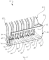
- Fig. 1 shows a section of a first embodiment of a heat exchanger 10 according to the invention comprising a first component 20 and a second component 60.
- the first component 20 is a heat exchanger block 20, which is advantageously made of aluminum
- the second component 60 is a collector box 60, which is preferably made of a plastic.
- the heat exchanger block 20 has a positioned border area 22, which is delimited by an border 24.
- a plurality of partial areas 26, which are evenly spaced apart from one another, are arranged at a distance to the border 24.
- the partial areas 26 are surrounded by a U-shaped recess 40, which is arranged in such a way that the opening of the "U" of the U-shaped recess 40 points to the border 24 of the positioned border area 22 and is spaced apart therefrom.
- the recesses 40 are advantageously embodied as slits, which completely penetrate the material of the positioned border area 22.
- the slits 40 surround the partial areas 26 on three sides by means of this embodiment according to the invention, so that a free end 30, which points away from the border 24 of the positioned border area 22, is formed, which is delimited by an outer border 32.
- a transition surface 28 is arranged in the opening of the "U" of the U-shaped recess 40, in each case in the transition area between the positioned border area 22 and the partial area 26.
- clamping noses 26 or guides 26 are provided in the positioned border area 22 of the heat exchanger block 20, which can be pushed or bent, respectively, onto a (non-illustrated) flange of the collector box 60 with their free end 30 with little effort, in order to establish the desired clamping connection between heat exchanger block 20 and collector box 60. This will be discussed in more detail below with reference to Fig. 2 .
- FIG. 2 shows the section of the first embodiment illustrated in Fig. 1 of a heat exchanger 10 according to the invention comprising a heat exchanger block 20 and a collector box 60.
- Heat exchanger block 20 and collector box 60 are connected to one another here by means of a clamping connection.
- the flange 64 which is arranged on the end of a side 62 of the collector box 60, can be seen clearly. It can furthermore be seen clearly here, how the positioned border area 22 of the heat exchanger block 20 encompasses the flange 64, wherein a sealing chamber 70 is formed between the underside of the flange 64 and the inner side of the positioned border area 22 of the heat exchanger block 20. A (non-illustrated) seal can be arranged in this sealing chamber 70, in order to further improve the sealing effect of the clamping connection between collector box 60 and heat exchanger block 20.
- the clamping connection between collector box 60 and heat exchanger block 20 is effected by the guides 26, which, as illustrated, are pushed or bent, respectively, inwards with their free end 30 in the direction of the collector box 60, and abut the upper side of the flange 64 at that location with their outer border 32.
- transition surfaces 28 in the transition area between the positioned border area 22 and the guides 26 is provided to avoid a sharp edge in this area, which could be created by pushing in or bending in, respectively, the guides 26.
- a sharp border in this area could trigger surface tensions, which could have a disadvantageous effect on the service life of the heat exchanger block 20, when the guides 26 are loaded.
- the positioned border area 22 of the heat exchanger block 20 remains substantially undeformed, and the border 24 thereof is in particular not bent over the flange 64 with the partial areas of the positioned border area 22 following directly on the border 24, so that bending loads in the material of the positioned border area 22 are avoided.
- a loading of connections on the heat exchanger block 20 is avoided with this, as well as a loading of the clamping connection between heat exchanger block 20 and collector box 60.
- the risk of damages to connections on the heat exchanger block 20 is significantly reduced, because bending stresses are not present in the positioned border area 22, which can be transferred into other areas of the heat exchanger block 20 as well as connections arranged there, so that the reliability and service life of the heat exchanger 10 according to the invention is significantly increased.
- the reduced loading of the clamping connection between heat exchanger block 20 and collector box 60 also significantly increases the reliability and service life thereof.
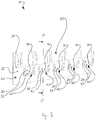
- Fig. 3 shows a partial view of a second embodiment of a heat exchanger 10 according to the invention comprising first component 20 and second component 60.
- the first component 20 is a heat exchanger block 20, which is advantageously made of aluminum
- the second component 60 is a collector box 60, which is advantageously made of a plastic.
- the clamping noses 26 are embodied in such a way that they have a convex curvature of bulge protruding towards the collector box 60.
- This curvature or bulge is furthermore embodied in such a way that the respective outer edge 32 on the respective free end 30 is closer to the collector box 60 than in the corners.
- the clamping connection according to the invention of this second embodiment will be discussed in more detail below with reference to Fig. 4 .
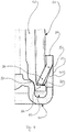
- Fig. 4 shows a sectional view of a clamping connection according to the invention along line S1 - S1 of the second embodiment illustrated in Fig. 3 .
- the side 62 of the collector box 60 ends in a flange 64.
- the heat exchanger block 20 encompasses this flange 64 with a positioned border area 22 in such a way that a sealing chamber 70 is formed between the underside of the flange 64 and the inner side of the positioned border area 22.
- a seal which is not illustrated here, can be arranged in this sealing chamber 70, in order to further improve the sealing between heat exchanger block 20 and collector box 60.
- the heat exchanger block 20 furthermore has a shoulder 50, which is directed inwards to the collector box 60, on which the side 62 of the collector box 60 abuts.
- the side 62 of the collector box 60 is pushed against the shoulder 50 by the guide 26, so that a seal is formed between heat exchanger block 20 and collector box 60.
- this seal can be further improved by means of a seal, which is arranged in the sealing chamber 70 and which is not illustrated here.
- the free end 30 of the guide 26 at least partially abuts the flange 64 of the collector box 60 with the outer edge 32 pointing away from the border 24 of the positioned border area 22.
Landscapes
- Engineering & Computer Science (AREA)
- Physics & Mathematics (AREA)
- Thermal Sciences (AREA)
- Mechanical Engineering (AREA)
- General Engineering & Computer Science (AREA)
- Heat-Exchange Devices With Radiators And Conduit Assemblies (AREA)
Priority Applications (1)
| Application Number | Priority Date | Filing Date | Title |
|---|---|---|---|
| EP17178095.0A EP3421920A1 (fr) | 2017-06-27 | 2017-06-27 | Échangeur de chaleur |
Applications Claiming Priority (1)
| Application Number | Priority Date | Filing Date | Title |
|---|---|---|---|
| EP17178095.0A EP3421920A1 (fr) | 2017-06-27 | 2017-06-27 | Échangeur de chaleur |
Publications (1)
| Publication Number | Publication Date |
|---|---|
| EP3421920A1 true EP3421920A1 (fr) | 2019-01-02 |
Family
ID=59269785
Family Applications (1)
| Application Number | Title | Priority Date | Filing Date |
|---|---|---|---|
| EP17178095.0A Withdrawn EP3421920A1 (fr) | 2017-06-27 | 2017-06-27 | Échangeur de chaleur |
Country Status (1)
| Country | Link |
|---|---|
| EP (1) | EP3421920A1 (fr) |
Cited By (1)
| Publication number | Priority date | Publication date | Assignee | Title |
|---|---|---|---|---|
| EP3892948A1 (fr) * | 2020-04-10 | 2021-10-13 | Valeo Autosystemy SP. Z.O.O. | Échangeur de chaleur |
Citations (7)
| Publication number | Priority date | Publication date | Assignee | Title |
|---|---|---|---|---|
| DE2703528A1 (de) * | 1977-01-28 | 1978-08-03 | Laengerer & Reich Kuehler | Wasserkuehler, insbesondere fuer eine brennkraftmaschine |
| GB2138335A (en) | 1983-04-19 | 1984-10-24 | Ford Motor Co | An assembly of two parts |
| EP0128806A1 (fr) | 1983-06-09 | 1984-12-19 | Societe Anonyme Des Usines Chausson | Echangeur de chaleur comportant des tubes engagés dans une plaque collectrice sertie sur une boîte à eau |
| US4649628A (en) | 1983-12-09 | 1987-03-17 | Societe Anonyme Des Usines Chausson | Method for crimping a tube end plate of a heat exchanger on a header box and heat exchanger obtained through this method |
| US5311933A (en) * | 1993-01-21 | 1994-05-17 | Lee Lanny R | Connection of tank to core for heat exchanger |
| DE102012202886A1 (de) | 2012-02-24 | 2013-08-29 | Behr Gmbh & Co. Kg | Wärmeübertrager |
| DE102014204272A1 (de) * | 2013-04-25 | 2014-10-30 | MAHLE Behr GmbH & Co. KG | Wärmeübertrager |
-
2017
- 2017-06-27 EP EP17178095.0A patent/EP3421920A1/fr not_active Withdrawn
Patent Citations (7)
| Publication number | Priority date | Publication date | Assignee | Title |
|---|---|---|---|---|
| DE2703528A1 (de) * | 1977-01-28 | 1978-08-03 | Laengerer & Reich Kuehler | Wasserkuehler, insbesondere fuer eine brennkraftmaschine |
| GB2138335A (en) | 1983-04-19 | 1984-10-24 | Ford Motor Co | An assembly of two parts |
| EP0128806A1 (fr) | 1983-06-09 | 1984-12-19 | Societe Anonyme Des Usines Chausson | Echangeur de chaleur comportant des tubes engagés dans une plaque collectrice sertie sur une boîte à eau |
| US4649628A (en) | 1983-12-09 | 1987-03-17 | Societe Anonyme Des Usines Chausson | Method for crimping a tube end plate of a heat exchanger on a header box and heat exchanger obtained through this method |
| US5311933A (en) * | 1993-01-21 | 1994-05-17 | Lee Lanny R | Connection of tank to core for heat exchanger |
| DE102012202886A1 (de) | 2012-02-24 | 2013-08-29 | Behr Gmbh & Co. Kg | Wärmeübertrager |
| DE102014204272A1 (de) * | 2013-04-25 | 2014-10-30 | MAHLE Behr GmbH & Co. KG | Wärmeübertrager |
Cited By (2)
| Publication number | Priority date | Publication date | Assignee | Title |
|---|---|---|---|---|
| EP3892948A1 (fr) * | 2020-04-10 | 2021-10-13 | Valeo Autosystemy SP. Z.O.O. | Échangeur de chaleur |
| WO2021204997A1 (fr) * | 2020-04-10 | 2021-10-14 | Valeo Autosystemy Sp. Z O.O. | Échangeur de chaleur |
Similar Documents
| Publication | Publication Date | Title |
|---|---|---|
| US4331201A (en) | Clamped connection | |
| CN1882818B (zh) | 热交换器,特别是用于汽车的增压空气冷却器 | |
| US9239196B2 (en) | Heat exchanger | |
| CN101111736B (zh) | 热交换器 | |
| US10215509B2 (en) | Coined header for heat exchanger | |
| EP3421920A1 (fr) | Échangeur de chaleur | |
| US20200271398A1 (en) | Integrated heat exchanger | |
| WO2013135541A2 (fr) | Échangeur thermique présentant un fond tubulaire ainsi que fond tubulaire destiné à celui-ci | |
| EP2434245B1 (fr) | Procédé d'assemblage pour échangeur thermique | |
| EP2689977A2 (fr) | Raclette d'essuie-glace servant à nettoyer des pare-brises de véhicule | |
| US5456311A (en) | Heat exchanger | |
| US4705104A (en) | Heat exchanger, in particular for a motor vehicle, having a rigid connection between a bundle of tubes and a water box and perforated plate assembly | |
| US20160273360A1 (en) | Cooling system for a gas turbine | |
| US9297593B2 (en) | Grooveless header plate | |
| US20160320148A1 (en) | Heat exchanger with a circumferential seal | |
| US20220403963A1 (en) | Hose clamp | |
| JP7429705B2 (ja) | ホースクランプ | |
| CN111148960B (zh) | 热交换器的密封结构以及热交换器 | |
| KR102252235B1 (ko) | 열교환기 | |
| US20220412673A1 (en) | Collector of a heat exchanger for a vehicle and such a heat exchanger | |
| US20210215442A1 (en) | Header tank and corresponding heat exchanger | |
| US20050110223A1 (en) | Cylinder-head gasket comprising an edge-to-edge stop ring which is connected by means of stapling | |
| EP3489610A1 (fr) | Échangeur de chaleur | |
| LU500870B1 (en) | Heat exchanger | |
| EP3447433B1 (fr) | Échangeur de chaleur et procédé de fabrication d'un échangeur de chaleur |
Legal Events
| Date | Code | Title | Description |
|---|---|---|---|
| PUAI | Public reference made under article 153(3) epc to a published international application that has entered the european phase |
Free format text: ORIGINAL CODE: 0009012 |
|
| STAA | Information on the status of an ep patent application or granted ep patent |
Free format text: STATUS: THE APPLICATION HAS BEEN PUBLISHED |
|
| AK | Designated contracting states |
Kind code of ref document: A1 Designated state(s): AL AT BE BG CH CY CZ DE DK EE ES FI FR GB GR HR HU IE IS IT LI LT LU LV MC MK MT NL NO PL PT RO RS SE SI SK SM TR |
|
| AX | Request for extension of the european patent |
Extension state: BA ME |
|
| STAA | Information on the status of an ep patent application or granted ep patent |
Free format text: STATUS: REQUEST FOR EXAMINATION WAS MADE |
|
| 17P | Request for examination filed |
Effective date: 20190502 |
|
| RBV | Designated contracting states (corrected) |
Designated state(s): AL AT BE BG CH CY CZ DE DK EE ES FI FR GB GR HR HU IE IS IT LI LT LU LV MC MK MT NL NO PL PT RO RS SE SI SK SM TR |
|
| STAA | Information on the status of an ep patent application or granted ep patent |
Free format text: STATUS: EXAMINATION IS IN PROGRESS |
|
| 17Q | First examination report despatched |
Effective date: 20200622 |
|
| STAA | Information on the status of an ep patent application or granted ep patent |
Free format text: STATUS: EXAMINATION IS IN PROGRESS |
|
| GRAP | Despatch of communication of intention to grant a patent |
Free format text: ORIGINAL CODE: EPIDOSNIGR1 |
|
| STAA | Information on the status of an ep patent application or granted ep patent |
Free format text: STATUS: GRANT OF PATENT IS INTENDED |
|
| INTG | Intention to grant announced |
Effective date: 20210218 |
|
| RAP1 | Party data changed (applicant data changed or rights of an application transferred) |
Owner name: MAHLE INTERNATIONAL GMBH |
|
| STAA | Information on the status of an ep patent application or granted ep patent |
Free format text: STATUS: THE APPLICATION IS DEEMED TO BE WITHDRAWN |
|
| 18D | Application deemed to be withdrawn |
Effective date: 20210629 |