EP3421903A1 - Heat exchange unit - Google Patents
Heat exchange unit Download PDFInfo
- Publication number
- EP3421903A1 EP3421903A1 EP17756155.2A EP17756155A EP3421903A1 EP 3421903 A1 EP3421903 A1 EP 3421903A1 EP 17756155 A EP17756155 A EP 17756155A EP 3421903 A1 EP3421903 A1 EP 3421903A1
- Authority
- EP
- European Patent Office
- Prior art keywords
- compressor
- working medium
- heat exchange
- heat
- exchange unit
- Prior art date
- Legal status (The legal status is an assumption and is not a legal conclusion. Google has not performed a legal analysis and makes no representation as to the accuracy of the status listed.)
- Withdrawn
Links
Images





Classifications
-
- F—MECHANICAL ENGINEERING; LIGHTING; HEATING; WEAPONS; BLASTING
- F04—POSITIVE - DISPLACEMENT MACHINES FOR LIQUIDS; PUMPS FOR LIQUIDS OR ELASTIC FLUIDS
- F04B—POSITIVE-DISPLACEMENT MACHINES FOR LIQUIDS; PUMPS
- F04B39/00—Component parts, details, or accessories, of pumps or pumping systems specially adapted for elastic fluids, not otherwise provided for in, or of interest apart from, groups F04B25/00 - F04B37/00
- F04B39/06—Cooling; Heating; Prevention of freezing
-
- F—MECHANICAL ENGINEERING; LIGHTING; HEATING; WEAPONS; BLASTING
- F24—HEATING; RANGES; VENTILATING
- F24F—AIR-CONDITIONING; AIR-HUMIDIFICATION; VENTILATION; USE OF AIR CURRENTS FOR SCREENING
- F24F1/00—Room units for air-conditioning, e.g. separate or self-contained units or units receiving primary air from a central station
- F24F1/06—Separate outdoor units, e.g. outdoor unit to be linked to a separate room comprising a compressor and a heat exchanger
- F24F1/20—Electric components for separate outdoor units
- F24F1/24—Cooling of electric components
-
- F—MECHANICAL ENGINEERING; LIGHTING; HEATING; WEAPONS; BLASTING
- F24—HEATING; RANGES; VENTILATING
- F24F—AIR-CONDITIONING; AIR-HUMIDIFICATION; VENTILATION; USE OF AIR CURRENTS FOR SCREENING
- F24F11/00—Control or safety arrangements
- F24F11/30—Control or safety arrangements for purposes related to the operation of the system, e.g. for safety or monitoring
- F24F11/41—Defrosting; Preventing freezing
-
- F—MECHANICAL ENGINEERING; LIGHTING; HEATING; WEAPONS; BLASTING
- F24—HEATING; RANGES; VENTILATING
- F24F—AIR-CONDITIONING; AIR-HUMIDIFICATION; VENTILATION; USE OF AIR CURRENTS FOR SCREENING
- F24F5/00—Air-conditioning systems or apparatus not covered by F24F1/00 or F24F3/00, e.g. using solar heat or combined with household units such as an oven or water heater
- F24F5/0089—Systems using radiation from walls or panels
-
- F—MECHANICAL ENGINEERING; LIGHTING; HEATING; WEAPONS; BLASTING
- F25—REFRIGERATION OR COOLING; COMBINED HEATING AND REFRIGERATION SYSTEMS; HEAT PUMP SYSTEMS; MANUFACTURE OR STORAGE OF ICE; LIQUEFACTION SOLIDIFICATION OF GASES
- F25B—REFRIGERATION MACHINES, PLANTS OR SYSTEMS; COMBINED HEATING AND REFRIGERATION SYSTEMS; HEAT PUMP SYSTEMS
- F25B1/00—Compression machines, plants or systems with non-reversible cycle
- F25B1/10—Compression machines, plants or systems with non-reversible cycle with multi-stage compression
-
- F—MECHANICAL ENGINEERING; LIGHTING; HEATING; WEAPONS; BLASTING
- F25—REFRIGERATION OR COOLING; COMBINED HEATING AND REFRIGERATION SYSTEMS; HEAT PUMP SYSTEMS; MANUFACTURE OR STORAGE OF ICE; LIQUEFACTION SOLIDIFICATION OF GASES
- F25B—REFRIGERATION MACHINES, PLANTS OR SYSTEMS; COMBINED HEATING AND REFRIGERATION SYSTEMS; HEAT PUMP SYSTEMS
- F25B31/00—Compressor arrangements
- F25B31/006—Cooling of compressor or motor
-
- F—MECHANICAL ENGINEERING; LIGHTING; HEATING; WEAPONS; BLASTING
- F25—REFRIGERATION OR COOLING; COMBINED HEATING AND REFRIGERATION SYSTEMS; HEAT PUMP SYSTEMS; MANUFACTURE OR STORAGE OF ICE; LIQUEFACTION SOLIDIFICATION OF GASES
- F25B—REFRIGERATION MACHINES, PLANTS OR SYSTEMS; COMBINED HEATING AND REFRIGERATION SYSTEMS; HEAT PUMP SYSTEMS
- F25B49/00—Arrangement or mounting of control or safety devices
- F25B49/02—Arrangement or mounting of control or safety devices for compression type machines, plants or systems
- F25B49/022—Compressor control arrangements
-
- F—MECHANICAL ENGINEERING; LIGHTING; HEATING; WEAPONS; BLASTING
- F25—REFRIGERATION OR COOLING; COMBINED HEATING AND REFRIGERATION SYSTEMS; HEAT PUMP SYSTEMS; MANUFACTURE OR STORAGE OF ICE; LIQUEFACTION SOLIDIFICATION OF GASES
- F25B—REFRIGERATION MACHINES, PLANTS OR SYSTEMS; COMBINED HEATING AND REFRIGERATION SYSTEMS; HEAT PUMP SYSTEMS
- F25B2309/00—Gas cycle refrigeration machines
- F25B2309/06—Compression machines, plants or systems characterised by the refrigerant being carbon dioxide
-
- F—MECHANICAL ENGINEERING; LIGHTING; HEATING; WEAPONS; BLASTING
- F25—REFRIGERATION OR COOLING; COMBINED HEATING AND REFRIGERATION SYSTEMS; HEAT PUMP SYSTEMS; MANUFACTURE OR STORAGE OF ICE; LIQUEFACTION SOLIDIFICATION OF GASES
- F25B—REFRIGERATION MACHINES, PLANTS OR SYSTEMS; COMBINED HEATING AND REFRIGERATION SYSTEMS; HEAT PUMP SYSTEMS
- F25B2600/00—Control issues
- F25B2600/25—Control of valves
- F25B2600/2513—Expansion valves
-
- F—MECHANICAL ENGINEERING; LIGHTING; HEATING; WEAPONS; BLASTING
- F25—REFRIGERATION OR COOLING; COMBINED HEATING AND REFRIGERATION SYSTEMS; HEAT PUMP SYSTEMS; MANUFACTURE OR STORAGE OF ICE; LIQUEFACTION SOLIDIFICATION OF GASES
- F25B—REFRIGERATION MACHINES, PLANTS OR SYSTEMS; COMBINED HEATING AND REFRIGERATION SYSTEMS; HEAT PUMP SYSTEMS
- F25B2700/00—Sensing or detecting of parameters; Sensors therefor
- F25B2700/21—Temperatures
- F25B2700/2106—Temperatures of fresh outdoor air
-
- F—MECHANICAL ENGINEERING; LIGHTING; HEATING; WEAPONS; BLASTING
- F25—REFRIGERATION OR COOLING; COMBINED HEATING AND REFRIGERATION SYSTEMS; HEAT PUMP SYSTEMS; MANUFACTURE OR STORAGE OF ICE; LIQUEFACTION SOLIDIFICATION OF GASES
- F25B—REFRIGERATION MACHINES, PLANTS OR SYSTEMS; COMBINED HEATING AND REFRIGERATION SYSTEMS; HEAT PUMP SYSTEMS
- F25B2700/00—Sensing or detecting of parameters; Sensors therefor
- F25B2700/21—Temperatures
- F25B2700/2115—Temperatures of a compressor or the drive means therefor
- F25B2700/21152—Temperatures of a compressor or the drive means therefor at the discharge side of the compressor
Definitions
- the present invention relates to a heat exchange unit. More particularly, the present invention relates to a heat exchange unit for use in refrigerating cycle apparatus.
- HFC hydrofluorocarbon
- Patent Document 1 describes a refrigerating cycle apparatus employing a working medium including 1,1,2-trifluoroethylene (HFO-1123).
- Patent Document 1 JP-A-2015-145452
- HFO-1123 in a high-temperature high-pressure state, upon reception of energy, undergoes an exothermic chemical reaction called a disproportionation reaction (self-decomposition reaction), which occurs like a chain reaction.
- a disproportionation reaction is a chemical reaction in which two or more molecules of the same kind react with each other to yield two or more different products. For refrigerating cycle apparatus employing working media including HFO-1123, it is therefore necessary to inhibit the occurrence of such a disproportionation reaction.
- an object of the present invention is to provide a heat exchange unit in which HFO-1123 can be inhibited from undergoing a disproportionation reaction.
- the present invention provides, in accordance with a first mode thereof, a heat exchange unit including: a compressor configured to compress a working medium that circulates through a refrigerating cycle, the working medium including 1,1,2-trifluoroethylene; a heat exchanger provided in the refrigerating cycle; and a heat dissipation means configured to dissipate heat generated in the compressor without using the working medium.
- the present invention provides, in accordance with a second mode thereof, a heat exchange unit that is the heat exchange unit described above which further includes: a blower configured to increase an air flow flowing along a surface of the heat exchanger to enhance heat exchange in the heat exchanger and a partition that separates a space where the blower is provided from a space where the compressor is provided.
- the partition has a vent hole formed therein at a position corresponding to the compressor, and the heat dissipation means includes the blower so that an air flow sent from the blower is used to dissipate the heat of the compressor.
- the present invention provides, in accordance with a third mode thereof, a heat exchange unit that is the heat exchange unit described above including an air deflector that directs a part of the air flow sent from the blower toward the compressor.
- the present invention provides, in accordance with a fourth mode thereof, a heat exchange unit that is the heat exchange unit described above wherein the blower includes a wind direction changing part that changes the direction of wind of the blower toward the compressor
- the present invention provides, in accordance with a fifth mode thereof, a heat exchange unit that is the heat exchange unit described above which includes: a detecting part that detects a temperature of the working medium discharged from the compressor; a determination part that determines whether or not the temperature of the working medium is higher than a predetermined temperature; and a first control part that controls the wind direction changing part in accordance with a determination made by the determination part.
- the first control part controls the wind direction changing part so that wind direction of the blower is directed toward the compressor.
- the present invention provides, in accordance with a sixth mode thereof, a heat exchange unit that is the heat exchange unit described above wherein a heat sink, as the heat dissipation means, is provided to the compressor, wherein the heat sink dissipates the heat generated in the compressor.
- the present invention provides, in accordance with a seventh mode thereof, a heat exchange unit that is the heat exchange unit described above which further includes, as the heat dissipation means, a drain-water supply unit that supplies drain water yielded in the refrigerating cycle to a surface of the compressor to cool the compressor.
- the present invention provides, in accordance with an eighth mode thereof, a heat exchange unit that is the heat exchange unit described above wherein the drain-water supply unit includes: a drain-water reservoir for reserving therein drain water yielded in the refrigerating cycle; a detecting part that detects a temperature of the working medium discharged from the compressor; a determination part that determines whether or not the temperature of the working medium is higher than a predetermined temperature; an electromagnetic valve that performs switching regarding the supply of the drain water from the drain-water reservoir to the surface of the compressor, and a second control part that controls the electromagnetic valve in accordance with a determination made by the determination part. In a case where the temperature of the working medium is higher than the predetermined temperature, the second control part opens the electromagnetic valve to supply the drain water from the drain-water reservoir to the surface of the compressor.
- the present invention can provide a heat exchange unit in which HFO-1123 can be inhibited from undergoing a disproportionation reaction.
- the working medium to be used in the invention includes 1,1,2-trifluoroethylene (HFO-1123).
- the working-medium characteristics of HFO-1123 are shown in Table 1 in terms of comparison with those of, in particular, R410A (pseudoazeotropic-mixture working medium composed of HFC-32 and HFC-125 in a mass ratio of 1:1).
- Cycle performance is indicated by the coefficient of performance and refrigerating capacity which are determined by the methods that will be described later.
- the coefficient of performance and refrigerating capacity of HFO-1123 are given as relative values (hereinafter referred to as "relative coefficient of performance" and "relative refrigerating capacity”) with respect to those of R410A as a reference (1.000).
- the global warming coefficient is a value for 100 years which is defined in Intergovernmental Panel on Climate Change (IPCC), Fourth assessment report (year 2007) or is determined by the method. In this description, values of GWP are such values unless otherwise indicated.
- IPCC Intergovernmental Panel on climate Change
- values of GWP are such values unless otherwise indicated.
- temperature glide is an important factor for evaluating the working medium; the smaller the value thereof, the more the working medium is preferred.
- the working medium to be used in the invention preferably includes HFO-1123.
- the working medium may contain any desired compounds commonly used as working media, besides HFO-1123 so long as the inclusion thereof does not lessen the effect of the invention.
- optionally usable compounds include HFCs, HFOs (HFCs having a carbon-carbon double bond) other than HFO-1123, and other ingredients which vaporize and liquefy together with HFO-1123.
- Preferred optional ingredients are HFCs and HFOs (HFCs having a carbon-carbon double bond) other than HFO-1123.
- Preferred optional ingredients are compounds which, when used in heat cycling in combination with HFO-1123, have the function of further heightening the relative coefficient of performance and the relative refrigerating capacity and which, despite this, can make the GWP and the temperature glide remain in acceptable ranges.
- the working medium contains such a compound in combination with HFO-1123, not only this working medium retains a low GWP and has better cycle performance but also the temperature glide exerts little influence.
- a working medium including, for example, HFO-1123 and an optional ingredient has a considerable temperature glide except for the case where the HFO-1123 and the optional ingredient are present as an azeotropic composition.
- the temperature glide of the working medium varies depending on the kind of the optional ingredient and the mixing ratio of HFO-1123 and optional ingredient.
- the mixture usually preferably is an azeotropic mixture or a pseudoazeotropic mixture such as R410A.
- Non-azeotropic compositions have a problem in that the compositions change in makeup when charged into refrigerators or air conditioners from pressure vessels.
- the refrigerant has leaked from the refrigerator or air conditioner, there is an extremely high possibility that the refrigerant within the refrigerator or air conditioner might have changed in makeup and it is difficult to recover the initial makeup of the refrigerant.
- an azeotropic or pseudoazeotropic mixture these problems can be avoided.
- Temperature glide is generally used as an index to the usability of working media which are mixtures. Temperature glide is defined as the property of differing in temperature between initiation and termination of, for example, vaporization in a vaporizer, or condensation in a condenser.
- the azeotropic mixtures have a temperature glide of 0, and pseudoazeotropic mixtures have temperature glides close to 0, like R410A, which has a temperature glide of 0.2.
- this working medium has a lowered temperature at the inlet of the vaporizer to pose a problem in that frosting is highly likely to occur.
- the working medium and the heat source fluid such as water or air, are generally caused to flow countercurrently in a heat exchanger in order to improve the heat exchange efficiency. Since the heat source fluid has a small temperature difference in the heat cycle system which is being stably operated, it is difficult to obtain a heat cycle system having a satisfactory energy efficiency with a non-azeotropic mixture medium having a large temperature glide. Consequently, in the case where a mixture is to be used as a working medium, this working medium is desired to have an appropriate temperature glide.
- HFCs are known to have higher GWPs than HFO-1123. It is hence preferable that an HFC to be used in combination with HFO-1123 is suitably selected from the standpoints of enabling the working medium to have improved cycle performance and retain a temperature glide within an appropriate range and, in particular, of making the working medium have a GWP within an acceptable range.
- preferred HFCs which less affect the ozone layer and less affect global warming are HFCs having a carbon number of from 1 to 5. These HFCs may be linear, branched, or cyclic.
- HFCs examples include HFC-32, difluoroethane, trifluoroethane, tetrafluoroethane, HFC-125, pentafluoropropane, hexafluoropropane, heptafluoropropane, pentafluorobutane, and heptafluorocyclopentane.
- HFC-32 1,1-difluoroethane
- HFC-143a 1,1,2,2-tetrafluoroethane
- HFC-134a 1,1,1,2-tetrafluoroethane
- HFC-125 More preferred are HFC-32, HFC-152a, HFC-134a, and HFC-125.
- One HFC may be used alone, or two or more HFCs may be used in combination.
- the content of an HFC in the working medium (100% by mass) can be selected at will in accordance with the properties required of the working medium.
- this working medium has an improved coefficient of performance and improved refrigerating capacity in the case where the content of HFC-32 is in the range of 1 to 99% by mass.
- this working medium has an improved coefficient of performance in the case where the content of HFC-134a is in the range of 1 to 99% by mass.
- the GWPs of the preferred HFCs are as follows.
- the GWP of HFC-32 is 675, that of HFC-134a is 1,430, and that of HFC-125 is 3,500. From the standpoint of obtaining a working medium having a reduced GWP, HFC-32 is the most preferred optional HFC ingredient.
- HFO-1123 and HFC-32 are capable of forming a nearly azeotropic mixture, or a pseudoazeotropic mixture, when used in proportions in the range of 99/1 to 1/99 in terms of mass ratio. Mixtures of the two have temperature glides close to 0 substantially irrespective of the proportions.
- HFC-32 is advantageous as an HFC to be used in combination with HFO-1123.
- the content of HFC-32 in the working medium is specifically preferably 20% by mass or more, more preferably 20 to 80% by mass, even more preferably 40 to 60% by mass.
- HFO-1234yf HFO-1234ze(E)
- HFO-1234yf HFO-1234ze(E)
- HFO-1234ze(E) One HFO other than HFO-1123 may be used alone, or two or more HFOs other than HFO-1123 may be used in combination.
- the content of HFOs other than HFO-1123 in the working medium (100% by mass) can be selected at will in accordance with the properties required of the working medium.
- this working medium has an improved coefficient of performance in the case where the content of HFO-1234yf or HFO-1234ze is in the range of 1 to 99% by mass.
- composition range (S) a preferred composition range is shown below as composition range (S).
- each compound shows the proportion (% by mass) of the compound to the total amount of the HFO-1123, HFO-1234yf, and other ingredients (HFC-32, etc.).
- the working medium which satisfies the composition range (S) has an exceedingly low GWP and a small temperature glide.
- This working medium can exhibit high refrigerating cycle performance which renders the working medium usable as a substitute for the conventional R410A from the standpoints of the coefficient of performance, refrigerating capacity, and critical temperature.
- the proportion of HFO-1123 to the sum of HFO-1123 and HFO-1234yf is more preferably 40 to 95% by mass, even more preferably 50 to 90% by mass, especially preferably 50 to 85% by mass, most preferably 60 to 85% by mass.
- the total content of HFO-1123 and HFO-1234yf in the working medium is more preferably 80 to 100% by mass, even more preferably 90 to 100% by mass, especially preferably 95 to 100% by mass.
- the working medium to be used in the invention preferably includes HFO-1123, HFC-32, and HFO-1234yf.
- a preferred composition range (P) is as follows.
- composition range (P) the abbreviation of each compound shows the proportion (% by mass) of the compound to the total amount of the HFO-1123, HFO-1234yf, and HFC-32. This applies to composition range (R), composition range (L), and composition range (M).
- R composition range
- L composition range
- M composition range
- the working medium having the composition is a working medium in which the properties possessed by HFO-1123, HFO-1234yf, and HFC-32 are exhibited while attaining a satisfactory balance thereamong and in which the drawbacks of these ingredients have been mitigated. Namely, this working medium has an exceedingly low GWP and, when used in heat cycling, has a small temperature glide and a certain degree of ability and efficiency, thereby attaining satisfactory cycle performance. It is preferable that the sum of HFO-1123 and HFO-1234yf is 70% by mass or more of the total amount of HFO-1123, HFO-1234yf, and HFC-32.
- a more preferred composition of the working medium to be used in the invention is one which contains 30 to 70% by mass HFO-1123, 4 to 40% by mass HFO-1234yf, and 0 to 30% by mass HFC-32, based on the total amount of the HFO-1123, HFO-1234yf, and HFC-32 and in which the content of HFO-1123 is 70% by mole or less based on the whole working medium.
- the working medium having a composition within that range shows higher effects in terms of the properties shown above and is a highly durable working medium in which the HFO-1123 is inhibited from undergoing a self-decomposition reaction. From the standpoint of the relative coefficient of performance, the content of HFC-32 is preferably 5% by mass or more, more preferably 8% by mass or more.
- the working medium to be used in the invention includes HFO-1123, HFO-1234yf, and HFC-32
- another preferred composition is as follows.
- the content of HFO-1123 is 70% by mole or less based on the whole working medium, the HFO-1123 is inhibited from undergoing a self-decomposition reaction and this working medium has high durability.
- composition range (R) is shown below.
- the working medium having the composition is a working medium in which the properties possessed by HFO-1123, HFO-1234yf, and HFC-32 are exhibited while attaining a satisfactory balance thereamong and in which the drawbacks of these ingredients have been mitigated. Namely, this working medium has a low GWP and intact durability and has a small temperature glide and high ability and efficiency when used in heat cycling, thereby attaining satisfactory cycle performance.
- composition range (R) A preferred range for the working medium of the invention which has the composition range (R) is shown below.
- the working medium having the composition is a working medium in which the properties possessed by HFO-1123, HFO-1234yf, and HFC-32 are exhibited while attaining a satisfactory balance thereamong and in which the drawbacks of these ingredients have been mitigated. Namely, this working medium has a low GWP and intact durability and has a smaller temperature glide and higher ability and efficiency when used in heat cycling, thereby attaining satisfactory cycle performance.
- a more preferred range (L) for the working medium of the invention which has the composition range (R) is shown below.
- the composition range (M) is even more preferred.
- the working medium having the composition range (M) is a working medium in which the properties possessed by HFO-1123, HFO-1234yf, and HFC-32 are exhibited while attaining a highly satisfactory balance thereamong and in which the drawbacks of these ingredients have been mitigated.
- this working medium is a working medium which has a GWP as low as 300 or less at the most and has intact durability and which, when used in heat cycling, has a temperature glide as small as less than 5.8 and has a relative coefficient of performance and a relative refrigerating capacity both close to 1, thereby attaining satisfactory cycle performance.
- the temperature glide has a reduced upper limit and the value of (relative coefficient of performance) ⁇ (relative refrigerating capacity) has an increased lower limit.
- the proportion of HFO-1234yf is more preferably 8% by mass or larger.
- the proportion of HFO-1234yf is more preferably 35% by mass or less.
- Another preferred working medium for use in the invention preferably includes HFO-1123, HFC-134a, HFC-125, and HFO-1234yf. This composition is effective in making the working medium have reduced combustibility.
- a more preferred working medium is one which includes HFO-1123, HFC-134a, HFC-125, and HFO-1234yf and in which: the total proportion of HFO-1123, HFC-134a, HFC-125, and HFO-1234yf to the whole working medium is larger than 90% by mass and 100% by mass or less; the proportion of HFO-1123 to the sum of HFO-1123, HFC-134a, HFC-125, and HFO-1234yf is 3% by mass or more and 35% by mass or less; the proportion of HFC-134a to said sum is 10% by mass or more and 53% by mass or less; the proportion of HFC-125 to said sum is 4% by mass or more and 50% by mass or less; and the proportion of HFO-1234yf to said sum is 5% by mass or more and 50% by mass or less.
- This working medium is noncombustible and highly safe, less affects the ozone layer and global warming, and can have better cycle performance when used in heat cycle systems.
- a most preferred working medium is one which includes HFO-1123, HFC-134a, HFC-125, and HFO-1234yf and in which: the total proportion of HFO-1123, HFC-134a, HFC-125, and HFO-1234yf to the whole working medium is larger than 90% by mass and 100% by mass or less; the proportion of HFO-1123 to the sum of HFO-1123, HFC-134a, HFC-125, and HFO-1234yf is 6% by mass or more and 25% by mass or less; the proportion of HFC-134a to said sum is 20% by mass or more and 35% by mass or less; the proportion of HFC-125 to said sum is 8% by mass or more and 30% by mass or less; and the proportion of HFO-1234yf to said sum is 20% by mass or more and 50% by mass or less.
- This working medium is noncombustible and even safer, even less affects the ozone layer and global warming, and can have even better cycle performance when used in heat cycle systems.
- the working medium to be used as the composition for use in the heat cycle system of the invention may contain carbon dioxide, hydrocarbons, chlorofluoroolefins (CFOs), hydrochlorofluoroolefins (HCFOs), etc. besides the optional ingredients shown above.
- Such other optional ingredients preferably are ingredients which less affect the ozone layer and less affect global warming.
- hydrocarbons examples include propane, propylene, cyclopropane, butane, isobutane, pentane, and isopentane.
- One hydrocarbon may be used alone, or two or more hydrocarbons may be used in combination.
- the working medium contains a hydrocarbon
- the content thereof based on the working medium is less than 10% by mass, preferably 1 to 5% by mass, more preferably 3 to 5% by mass.
- mineral-oil-based refrigerating oils have better solubility in this working medium.
- Examples of the CFOs include chlorofluoropropenes and chlorofluoroethylenes. From the standpoint of easily reducing the combustibility of the working medium without considerably lowering the cycle performance of the working medium, preferred CFOs are 1,1-dichloro-2,3,3,3-tetrafluoropropene (CFO-1214ya), 1,3-dichloro-1,2,3,3-tetrafluoropropene (CFO-1214yb), and 1,2-dichloro-1,2-difluoroethylene (CFO-1112).
- CFO-1214ya 1,1-dichloro-2,3,3,3-tetrafluoropropene
- CFO-1214yb 1,3-dichloro-1,2,3,3-tetrafluoropropene
- CFO-1112 1,2-dichloro-1,2-difluoroethylene
- One CFO may be used alone, or two or more CFOs may be used in combination.
- the working medium contains a CFO
- the content thereof based on the working medium is less than 10% by mass, preferably 1 to 8% by mass, more preferably 2 to 5% by mass.
- the CFO content is not less than the lower limit, the combustibility of this working medium is easy to be reduced.
- the CFO content is not higher than the upper limit, satisfactory cycle performance is easy to be obtained.
- HCFOs examples include hydrochlorofluoropropenes and hydrochlorofluoroethylenes. From the standpoint of easily reducing the combustibility of the working medium without considerably lowering the cycle performance of the working medium, preferred HCFOs are 1-chloro-2,3,3,3-tetrafluoropropene (HCFO-1224yd) and 1-chloro-1,2-difluoroethylene (HCFO-1122).
- One HCFO may be used alone, or two or more HCFOs may be used in combination.
- the content of the HCFO in the working medium is less than 10% by mass, preferably 1 to 8% by mass, more preferably 2 to 5% by mass.
- the HCFO content is not less than the lower limit, the combustibility of this working medium is easy to be reduced.
- the HCFO content is not higher than the upper limit, satisfactory cycle performance is easy to be obtained.
- the total content of the other optional ingredients in the working medium is less than 10% by mass, preferably 8% by mass or less, more preferably 5% by mass or less.
- FIG. 1 is a view for explaining a refrigerating cycle apparatus including a heat exchange unit according to the present invention.
- the refrigerating cycle apparatus 100 includes a compressor 11, a heat exchanger 12, an expansion valve 13, a heat exchanger 14, an accumulator 15, a selector valve 16, and blowers 17 and 21.
- FIG. 1 shows an example including a heat exchange unit 1 which includes the compressor 11, heat exchanger 12, expansion valve 13, accumulator 15, selector valve 16, and blower 21, the heat exchange unit 1 according to the present invention is only required to include at least the compressor 11 and the heat exchanger 12.
- the refrigerating cycle apparatus 100 is, for example, an air conditioner, a refrigerator, or the like.
- the heat exchange unit 1 corresponds to an outdoor unit and the heat exchanger 14 corresponds to the heat exchanger included in an indoor unit.
- the refrigerating cycle apparatus 100 shown in FIG. 1 is in such a state that the heat exchanger 12 is dissipating heat and the heat exchanger 14 is absorbing heat.
- FIG. 1 shows the air conditioner which is in the state of performing a cooling operation or a defrosting operation.
- a working medium including HFO-1123 is circulated through the compressor 11, heat exchanger 12, expansion valve 13, heat exchanger 14, and accumulator 15 in this order to form a refrigerating cycle.
- the high-temperature high-pressure working medium (vapor) discharged from the compressor 11 is supplied to the heat exchanger 12 via the selector valve 16.
- the working medium supplied to the heat exchanger 12 undergoes heat dissipation by emitting heat to the air surrounding the heat exchanger 12 and condenses thereby.
- an air flow that is, the air flow amount
- heat exchange heat dissipation
- the working medium depressurized by the expansion valve 13 is supplied to the heat exchanger 14 and expands in the heat exchanger 14 to come to have a low temperature and a low pressure, thereby lowering the surface temperature of the heat exchanger 14.
- the heat exchanger 14 having a lowered surface temperature absorbs heat from the surrounding air, thereby cooling the air surrounding the heat exchanger 14.
- a blower 17 in the vicinity of the heat exchanger 14, an air flow flowing along a surface of the heat exchanger 14 can be increased, and heat exchange (heat absorption) in the heat exchanger 14 can be enhanced.
- the low-temperature gaseous working medium returns to the compressor 11 via the selector valve 16 and the accumulator 15.
- the working medium which is entering the accumulator 15 has partly liquefied, and the liquefied portion of the working medium is reserved in the accumulator 15.
- FIG. 2 shows a refrigerating cycle apparatus 200 which is in such a state that a heat exchanger 12 is absorbing heat and a heat exchanger 14 is dissipating heat.
- the refrigerating cycle apparatus 200 is, for example, an air conditioner
- FIG. 2 shows the air conditioner which is in the state of performing a heating operation.
- a working medium including HFO-1123 is circulated through a compressor 11, the heat exchanger 14, an expansion valve 13, the heat exchanger 12, and an accumulator 15 in this order to form a refrigerating cycle.
- the direction of circulation of the working medium in the refrigerating cycle apparatus 200 shown in FIG. 2 is reverse to that in the refrigerating cycle apparatus 100 shown in FIG. 1 .
- the direction of circulation of the working medium can be selected by operating the selector valve 16.
- the high-temperature high-pressure working medium (vapor) discharged from the compressor 11 is supplied to the heat exchanger 14 via the selector valve 16.
- the working medium supplied to the heat exchanger 14 undergoes heat dissipation by emitting heat to the air surrounding the heat exchanger 14 and condenses thereby.
- a blower 17 in the vicinity of the heat exchanger 14 an air flow can be made to flow in an increased amount along a surface of the heat exchanger 14, and heat exchange (heat dissipation) in the heat exchanger 14 can be enhanced.
- the working medium which has become liquid through the condensation is supplied from the heat exchanger 14 to the expansion valve 13 and depressurized by the expansion valve 13.
- the working medium depressurized by the expansion valve 13 is supplied to the heat exchanger 12 and expands in the heat exchanger 12 to come to have a low temperature and a low pressure, thereby lowering the surface temperature of the heat exchanger 12.
- the heat exchanger 12 having a lowered surface temperature absorbs heat from the surrounding air.
- a blower 21 in the vicinity of the heat exchanger 12
- an air flow flowing along a surface of the heat exchanger 12 can be increased, and heat exchange (heat absorption) in the heat exchanger 12 can be enhanced.
- the low-temperature gaseous working medium returns to the compressor 11 via the selector valve 16 and the accumulator 15.
- the working medium which is entering the accumulator 15 has partly liquefied, and the liquefied portion of the working medium is reserved in the accumulator 15.
- the heat exchange unit includes: a compressor configured to compress a working medium that circulates through a refrigerating cycle, the working medium including 1,1,2-trifluoroethylene, a heat exchanger provided in the refrigerating cycle, and a heat dissipation means configured to dissipate heat generated in the compressor without using the working medium. Since the heat exchange unit according to the present invention includes a heat dissipation means configured to dissipate heat generated in the compressor, it is possible to enhance cooling of the compressor. Consequently, the HFO-1123 can be inhibited from undergoing a disproportionation reaction.
- a blower 21 (see FIG. 3A ) is used to configure a heat dissipation means. Namely, an air flow sent from the blower 21 is used to dissipate the heat of the compressor.
- a heat sink 51 (see FIG. 8 ) is used to configure a heat dissipation means. Namely, by providing the heat sink 51 to a compressor 11, the heat generated in the compressor is dissipated.
- a drain-water supply unit (see the drain-water reservoir 62, etc. shown in FIG. 9 ) is used to configure a heat dissipation means. Namely, drain water yielded in the refrigerating cycle is supplied to a surface of the compressor using the drain-water supply unit to thereby dissipate the heat of the compressor.
- FIG. 3A to FIG. 3C respectively are a top plan view, a front view, and a side view of a heat exchange unit according to this embodiment.
- the heat exchange unit 1 includes a housing 10 constituted of steel sheet, etc. and, accommodated therein, a compressor 11, a heat exchanger 12, an accumulator 15, and a blower 21.
- the heat exchange unit 1 shown in FIG. 3A to FIG. 3C is an example, and the heat exchange unit 1 may include the expansion valve 13 and selector valve 16 shown in FIG. 1 and FIG. 2 .
- a part of the housing 10 is removed in order to show the state of the inside of the heat exchange unit 1.
- the heat exchanger 12 has the shape of the letter L in terms of plan view shape, and is provided along the back face 10_1 and a side face 10_2 of the housing 10.
- the blower 21 is fixed to the top face 10_5 and bottom face 10_6 of the housing 10 with a fixing member 22.
- the blower 21 is driven by a motor 23.
- the back face 10_1 and front face 10_3 of the housing 10 have vent holes and the rotation of the blower 21 results in a wind blowing in the direction indicated by the arrows (broken lines) in FIG. 3A .
- an air flow flowing along the surface of the heat exchanger 12 can be increased, and heat exchange in the heat exchanger 12 can be enhanced.
- the heat exchanger 12 and the blower 21 are provided in a space 31 surrounded by the back face 10_1, side face 10_2, and front face 10_3 of the housing 10 and by a partition 25.
- the compressor 11 and the accumulator 15 are provided in a space 32 surrounded by the back face 10_1, side face 10_4, and front face 10_3 of the housing 10 and by the partition 25.
- a pipeline 18 on the outlet side of the compressor 11 and a pipeline on the inlet side of the accumulator 15 are not shown in the drawings in this description, these pipelines are connected to the selector valve 16 shown in FIG. 1 and FIG. 2 .
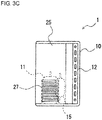
- the partition 25 has a vent hole 27 formed therein at a position corresponding to the compressor 11, as shown in FIG. 3C .
- the vent hole 27 is formed in a position where the compressor 11 and the partition 25 overlap each other when the heat exchange unit 1 is viewed from a side.
- the position where the vent hole 27 is formed is indicated by a broken line.
- the compressor 11 and the accumulator 15 are indicated by broken lines in order to clearly shown the position of the vent hole 27.
- FIG. 3C shows an example in which a plurality of vent holes 27 are formed in the partition 25,
- the shape of the vent holes in the heat exchange unit 1 is not limited to the shape in the example.
- a vent hole 28 having a size corresponding to the compressor 11 may be formed in the partition 25 as shown in FIG. 4 .
- the vent hole 28 is formed at a position in the partition 25 which corresponds to the compressor 11, that is, in a position where the compressor 11 and the partition 25 overlap each other when the heat exchange unit 1 is viewed from a side.
- the partition 25 hence has a vent hole 27 formed therein at a position corresponding to the compressor 11 as shown in FIG. 3C .
- Embodiment 2 of the present invention is explained next.
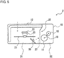
- FIG. 5 is a top plan view showing a heat exchange unit 2 according to embodiment 2. Constituent elements in FIG. 5 which are the same as in embodiment 1 are designated by the same numerals to avoid duplication of explanation.
- the heat exchange unit 2 includes an air deflector 35 that directs a part of the air flow sent from the blower 21 toward the compressor 11.
- the air deflector 35 can be formed using, for example, a steel material or a resin material.
- the air deflector 35 may have a height corresponding to the compressor 11 and, in this case, is fixed to the bottom face 10_6 of the housing 10 (see FIG. 3B ).
- the air deflector 35 may be formed so as to extend from the bottom face to the top face of the housing 10. In this case, the air deflector 35 can be fixed to the top face 10_5 and the bottom face 10_6 of the housing 10 (see FIG. 3 ).
- the air deflector 35 may be configured to be rotatable on an axis extending along the vertical direction of the housing 10. Thus, the direction of the air flow deflected by the air deflector 35 can be regulated and the wind direction can be more reliably directed toward the compressor 11.
- the heat exchange unit 2 includes the air deflector 35, an air flow around the compressor 11 can be increased. Consequently, cooling of the compressor 11 can be enhanced more than in the heat exchange unit 1 according to embodiment 1 and the HFO-1123 can be more effectively inhibited from undergoing a disproportionation reaction.
- Embodiment 3 of the present invention is explained next.
- FIG. 6 is a front view showing a heat exchange unit 3 according to embodiment 3.
- FIG. 7A and FIG. 7B are top plan views for explaining operations of the heat exchange unit 3 according to embodiment 3.
- the heat exchange unit 3 according to this embodiment differs from the heat exchange unit 1 according to embodiment 1 in that the heat exchange unit 3 includes a wind direction changing part 41 that changes the direction of wind of the blower 21 toward the compressor 11. Except for this, the heat exchange unit 3 has the same configuration as the heat exchange unit 1 explained as embodiment 1. Hence, the same constituent elements are designated by the same numerals to avoid duplication of explanation.
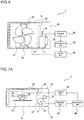
- the heat exchange unit 3 includes the wind direction changing part 41, a detecting part 42, a determination part 43, and a control part 44.
- the wind direction changing part 41 is configured to be capable of changing the direction of wind of the blower 21 toward the compressor 11. Specifically, as shown in FIG. 7A and FIG. 7B , the wind direction changing part 41 changes the direction of the blower 21 by rotating the blower 21 on a rotation axis 48 extending along the vertical direction of the heat exchange unit 3.
- FIG. 7A shows the state in which the direction of the wind from the blower 21 is normal
- FIG. 7B shows the state in which the blower 21 faces toward the compressor 11.
- the detecting part 42 detects the temperature of the working medium discharged from the compressor 11, specifically, the temperature of the working medium within the pipeline 18 on the outlet side of the compressor 11.
- the determination part 43 determines whether or not the temperature of the working medium detected by the detecting part 42 is higher than a predetermined temperature.
- the control part 44 controls the wind direction changing part 41 in accordance with a determination made by the determination part 43. Specifically, in the case where the temperature of the working medium is higher than the predetermined temperature, the control part 44 controls the wind direction changing part 41 so that the direction of wind from the blower 21 is directed toward the compressor 11, as shown in FIG. 7B .
- the predetermined temperature on the basis of which the determination part 43 makes a determination, is set at a temperature lower than the temperature at which the HFO-1123 included in the working medium undergoes a disproportionation reaction. That is, since the working medium is prone to undergo a disproportionation reaction at higher temperatures, the direction of wind from the blower 21 is directed toward the compressor 11 to enhance cooling of the compressor 11 before the working medium undergoes the disproportionation reaction. Thus, the disproportionation reaction can be inhibited from occurring in the compressor 11. The disproportionation reaction can be more reliably inhibited by setting the predetermined temperature at a relatively low temperature.
- Embodiment 4 according to the present invention is explained next.
- FIG. 8 is a top plan view showing a heat exchange unit 4 according to embodiment 4. Constituent elements in FIG. 8 which are the same as in embodiment 1 are designated by the same numerals to avoid duplication of explanation.
- FIG. 8 shows, in the heat exchange unit 4 according to this embodiment, a heat sink 51 that dissipates the heat generated in the compressor 11 is provided to the compressor 11.
- FIG. 8 shows the case where the heat sink 51 is provided to a part of the periphery of the compressor 11.
- the heat sink 51 may be provided to the whole periphery of the compressor 11.
- the heat sink 51 is formed in a portion of the periphery of the compressor 11 which faces the vent hole 27 formed in the partition 25.
- the heat exchange unit 4 includes the heat sink 51, cooling of the compressor 11 can be enhanced and the HFO-1123 can be more effectively inhibited from undergoing a disproportionation reaction.
- This embodiment may be combined with embodiment 2.
- the air deflector 35 shown in FIG. 5 may be provided in the heat exchange unit 4 shown in FIG. 8 .
- This configuration can more effectively cool the compressor 11.
- This embodiment may also be combined with embodiment 3.
- the wind direction changing part 41, detecting part 42, determination part 43, and control part 44 shown in FIG. 6 and FIGs 7A and 7B may be provided to the heat exchange unit 4 shown in FIG. 8 . This configuration can more effectively cool the compressor 11.
- the heat exchange unit shown in FIG. 8 may be configured so that the partition 25 has no vent hole 27.
- the heat of the compressor 11 can be dissipated via the heat sink 51 without necessitating disposition of vent hole in the partition 25.
- Embodiment 5 according to the present invention is explained next.
- FIG. 9 is a side view showing a heat exchange unit 5 according to embodiment 5.
- the heat exchange unit 5 according to this embodiment differs from the heat exchange unit 1 according to embodiment 1 in that drain water yielded in the refrigerating cycle is used to cool the compressor 11. Except for this, the heat exchange unit 5 has the same configuration as the heat exchange unit 1 explained as embodiment 1. Hence, the same constituent elements are designated by the same numerals to avoid duplication of explanation.
- the heat exchange unit 5 includes a pipeline 61, a drain-water reservoir 62, a pipeline 63, and an electromagnetic valve 64, which configure a drain-water supply unit.
- the drain-water reservoir 62 reserves therein drain water yielded in the refrigerating cycle.
- drain water is yielded on the heat exchanger 14 of the refrigerating cycle apparatus 100 shown in FIG. 1 .
- the drain water yielded in the refrigerating cycle is supplied to the drain-water reservoir 62 via the pipeline 61.
- the drain water reserved in the drain-water reservoir 62 is supplied to a surface of the compressor 11 via the pipeline 63.
- the supply of the drain water to the surface of the compressor 11 from the drain-water reservoir 62 can be switched using the electromagnetic valve 64. By thus supplying the drain water to the surface of the compressor 11, the compressor 11 can be cooled.
- the drain-water supply unit of the heat exchange unit 5 further includes a detecting part 66, a determination part 67, and a control part 68.
- the detecting part 66 detects the temperature of the working medium discharged from the compressor 11, specifically, the temperature of the working medium within the pipeline 18 on the outlet side of the compressor 11.
- the determination part 67 determines whether or not the temperature of the working medium detected by the detecting part 66 is higher than a predetermined temperature.
- the control part 68 controls the electromagnetic valve 64 in accordance with a determination made by the determination part 67. Specifically, in the case where the temperature of the working medium is higher than the predetermined temperature, the control part 68 opens the electromagnetic valve 64 to supply drain water from the drain-water reservoir 62 to a surface of the compressor 11 and thereby cool the compressor 11.
- the predetermined temperature on the basis of which the determination part 67 makes a determination, is set at a temperature lower than the temperature at which the HFO-1123 included in the working medium undergoes a disproportionation reaction. That is, since the working medium is prone to undergo a disproportionation reaction at higher temperatures, the electromagnetic valve 64 is opened to supply the drain water to a surface of the compressor 11 and cool the compressor 11 before the working medium undergoes the disproportionation reaction. Thus, the disproportionation reaction can be inhibited from occurring in the compressor 11. The disproportionation reaction can be more reliably inhibited by setting the predetermined temperature at a relatively low temperature.
- the pipeline 63 that supply the drain water to the surface of the compressor 11 preferably has such a shape that the drain water is evenly supplied to the surface of the compressor 11. For example, by attaching a shower head to the end of the pipeline 63, the drain water can be evenly supplied to the surface of the compressor 11.
- the pipeline 63 may be configured so that the drain water is preferentially supplied to that portion of the surfaces of the compressor 11 which faces the vent hole 27 formed in the partition 25 (see FIG. 3A ). By thus supplying the drain water preferentially to the portion of the compressor 11 which receives the wind, the vaporization of the drain water is accelerated and cooling of the compressor 11 can be enhanced.
- This embodiment may be combined with embodiment 2.
- the air deflector 35 shown in FIG. 5 may be provided in the heat exchange unit 5 shown in FIG. 9 .
- This configuration can more effectively cool the compressor 11.
- This embodiment may also be combined with embodiment 3.
- the wind direction changing part 41, detecting part 42, determination part 43, and control part 44 shown in FIG. 6 and FIGs 7A and 7B may be provided to the heat exchange unit 5 shown in FIG. 9 .
- This configuration can more effectively cool the compressor 11.
- the detecting parts 42 and 66 can be integrated, the determination parts 43 and 67 can be integrated, and the control parts 44 and 68 can be integrated.
- this embodiment may be combined with embodiment 4.
- the heat sink 51 shown in FIG. 8 may be provided to the compressor 11 shown in FIG. 9 . This configuration can more effectively cool the compressor 11.
- the heat exchange unit shown in FIG. 9 may be configured so that the partition 25 has no vent hole.
- the heat of the compressor 11 can be dissipated using drain water without necessitating disposition of vent holes in the partition 25.
Landscapes
- Engineering & Computer Science (AREA)
- Mechanical Engineering (AREA)
- General Engineering & Computer Science (AREA)
- Physics & Mathematics (AREA)
- Thermal Sciences (AREA)
- Combustion & Propulsion (AREA)
- Chemical & Material Sciences (AREA)
- Life Sciences & Earth Sciences (AREA)
- Sustainable Development (AREA)
- Lubricants (AREA)
- Structures Of Non-Positive Displacement Pumps (AREA)
- Other Air-Conditioning Systems (AREA)
- Compressor (AREA)
Abstract
Description
- The present invention relates to a heat exchange unit. More particularly, the present invention relates to a heat exchange unit for use in refrigerating cycle apparatus.
- Working media (hereinafter referred to also as "refrigerants") based on a hydrofluorocarbon (HFC) are in extensive use in refrigerating cycle apparatus such as air conditioners and refrigerators. However, it has been pointed out that HFCs have large values of global warming potential (GWP) and may be a cause of global warming. It is hence of urgent necessity to develop a working medium for refrigerating cycles which less affects the ozone layer and has a small value of global warming potential. Working media for refrigerating cycles which include a hydrofluoroolefin (HFO) having a carbon-carbon double bond which is apt to be cleaved by OH radicals present in the air are being investigated as working media which less affect the ozone layer and less affect the global warming.
Patent Document 1 describes a refrigerating cycle apparatus employing a working medium including 1,1,2-trifluoroethylene (HFO-1123). - Patent Document 1:
JP-A-2015-145452 - There is a case where HFO-1123 in a high-temperature high-pressure state, upon reception of energy, undergoes an exothermic chemical reaction called a disproportionation reaction (self-decomposition reaction), which occurs like a chain reaction. A disproportionation reaction is a chemical reaction in which two or more molecules of the same kind react with each other to yield two or more different products. For refrigerating cycle apparatus employing working media including HFO-1123, it is therefore necessary to inhibit the occurrence of such a disproportionation reaction.
- In view of that problem, an object of the present invention is to provide a heat exchange unit in which HFO-1123 can be inhibited from undergoing a disproportionation reaction.
- The present invention provides, in accordance with a first mode thereof, a heat exchange unit including: a compressor configured to compress a working medium that circulates through a refrigerating cycle, the working medium including 1,1,2-trifluoroethylene; a heat exchanger provided in the refrigerating cycle; and a heat dissipation means configured to dissipate heat generated in the compressor without using the working medium.
- The present invention provides, in accordance with a second mode thereof, a heat exchange unit that is the heat exchange unit described above which further includes: a blower configured to increase an air flow flowing along a surface of the heat exchanger to enhance heat exchange in the heat exchanger and a partition that separates a space where the blower is provided from a space where the compressor is provided. The partition has a vent hole formed therein at a position corresponding to the compressor, and the heat dissipation means includes the blower so that an air flow sent from the blower is used to dissipate the heat of the compressor.
- The present invention provides, in accordance with a third mode thereof, a heat exchange unit that is the heat exchange unit described above including an air deflector that directs a part of the air flow sent from the blower toward the compressor.
- The present invention provides, in accordance with a fourth mode thereof, a heat exchange unit that is the heat exchange unit described above wherein the blower includes a wind direction changing part that changes the direction of wind of the blower toward the compressor
- The present invention provides, in accordance with a fifth mode thereof, a heat exchange unit that is the heat exchange unit described above which includes: a detecting part that detects a temperature of the working medium discharged from the compressor; a determination part that determines whether or not the temperature of the working medium is higher than a predetermined temperature; and a first control part that controls the wind direction changing part in accordance with a determination made by the determination part. In a case where the temperature of the working medium is higher than the predetermined temperature, the first control part controls the wind direction changing part so that wind direction of the blower is directed toward the compressor.
- The present invention provides, in accordance with a sixth mode thereof, a heat exchange unit that is the heat exchange unit described above wherein a heat sink, as the heat dissipation means, is provided to the compressor, wherein the heat sink dissipates the heat generated in the compressor.
- The present invention provides, in accordance with a seventh mode thereof, a heat exchange unit that is the heat exchange unit described above which further includes, as the heat dissipation means, a drain-water supply unit that supplies drain water yielded in the refrigerating cycle to a surface of the compressor to cool the compressor.
- The present invention provides, in accordance with an eighth mode thereof, a heat exchange unit that is the heat exchange unit described above wherein the drain-water supply unit includes: a drain-water reservoir for reserving therein drain water yielded in the refrigerating cycle; a detecting part that detects a temperature of the working medium discharged from the compressor; a determination part that determines whether or not the temperature of the working medium is higher than a predetermined temperature; an electromagnetic valve that performs switching regarding the supply of the drain water from the drain-water reservoir to the surface of the compressor, and a second control part that controls the electromagnetic valve in accordance with a determination made by the determination part. In a case where the temperature of the working medium is higher than the predetermined temperature, the second control part opens the electromagnetic valve to supply the drain water from the drain-water reservoir to the surface of the compressor.
- The present invention can provide a heat exchange unit in which HFO-1123 can be inhibited from undergoing a disproportionation reaction.
-
-
FIG. 1 is a view for explaining a refrigerating cycle apparatus. -
FIG. 2 is a view for explaining a refrigerating cycle apparatus. -
FIG. 3A is a top plan view showing a heat exchange unit according toembodiment 1. -
FIG. 3B is a front view showing the heat exchange unit according toembodiment 1. -
FIG. 3C is a side view showing the heat exchange unit according toembodiment 1. -
FIG. 4 is a side view showing another heat exchange unit according toembodiment 1. -
FIG. 5 is a top plan view showing a heat exchange unit according toembodiment 2. -
FIG. 6 is a front view showing a heat exchange unit according toembodiment 3. -
FIG. 7A is a top plan view for explaining an operation of the heat exchange unit according toembodiment 3. -
FIG. 7B is a top plan view for explaining an operation of the heat exchange unit according toembodiment 3. -
FIG. 8 is a top plan view showing a heat exchange unit according to embodiment 4. -
FIG. 9 is a side view showing a heat exchange unit according toembodiment 5. - Embodiments of the present invention are explained below by reference to the drawings.
- First, the working medium (refrigerant) to be used in the refrigerating cycle apparatus of the invention is explained.
- The working medium to be used in the invention includes 1,1,2-trifluoroethylene (HFO-1123). The working-medium characteristics of HFO-1123 are shown in Table 1 in terms of comparison with those of, in particular, R410A (pseudoazeotropic-mixture working medium composed of HFC-32 and HFC-125 in a mass ratio of 1:1). Cycle performance is indicated by the coefficient of performance and refrigerating capacity which are determined by the methods that will be described later. The coefficient of performance and refrigerating capacity of HFO-1123 are given as relative values (hereinafter referred to as "relative coefficient of performance" and "relative refrigerating capacity") with respect to those of R410A as a reference (1.000). The global warming coefficient (GWP) is a value for 100 years which is defined in Intergovernmental Panel on Climate Change (IPCC), Fourth assessment report (year 2007) or is determined by the method. In this description, values of GWP are such values unless otherwise indicated. In the case of a working medium constituted of a mixture, temperature glide is an important factor for evaluating the working medium; the smaller the value thereof, the more the working medium is preferred.
-
Table 1 R410A HFO-1123 Relative coefficient of performance 1.000 0.921 Relative refrigerating capacity 1.000 1.146 Temperature glide [°C] 0.2 0 GWP 2088 0.3 - The working medium to be used in the invention preferably includes HFO-1123. The working medium may contain any desired compounds commonly used as working media, besides HFO-1123 so long as the inclusion thereof does not lessen the effect of the invention. Examples of such optionally usable compounds (optional ingredients) include HFCs, HFOs (HFCs having a carbon-carbon double bond) other than HFO-1123, and other ingredients which vaporize and liquefy together with HFO-1123. Preferred optional ingredients are HFCs and HFOs (HFCs having a carbon-carbon double bond) other than HFO-1123.
- Preferred optional ingredients are compounds which, when used in heat cycling in combination with HFO-1123, have the function of further heightening the relative coefficient of performance and the relative refrigerating capacity and which, despite this, can make the GWP and the temperature glide remain in acceptable ranges. In the case where the working medium contains such a compound in combination with HFO-1123, not only this working medium retains a low GWP and has better cycle performance but also the temperature glide exerts little influence.
- A working medium including, for example, HFO-1123 and an optional ingredient has a considerable temperature glide except for the case where the HFO-1123 and the optional ingredient are present as an azeotropic composition. The temperature glide of the working medium varies depending on the kind of the optional ingredient and the mixing ratio of HFO-1123 and optional ingredient.
- In the case of using a mixture as the working medium, the mixture usually preferably is an azeotropic mixture or a pseudoazeotropic mixture such as R410A. Non-azeotropic compositions have a problem in that the compositions change in makeup when charged into refrigerators or air conditioners from pressure vessels. In addition, in the case where such a refrigerant has leaked from the refrigerator or air conditioner, there is an extremely high possibility that the refrigerant within the refrigerator or air conditioner might have changed in makeup and it is difficult to recover the initial makeup of the refrigerant. Meanwhile, in the case where an azeotropic or pseudoazeotropic mixture is used, these problems can be avoided.
- "Temperature glide" is generally used as an index to the usability of working media which are mixtures. Temperature glide is defined as the property of differing in temperature between initiation and termination of, for example, vaporization in a vaporizer, or condensation in a condenser. The azeotropic mixtures have a temperature glide of 0, and pseudoazeotropic mixtures have temperature glides close to 0, like R410A, which has a temperature glide of 0.2.
- In case where the temperature glide is large, this working medium has a lowered temperature at the inlet of the vaporizer to pose a problem in that frosting is highly likely to occur. Furthermore, in a heat cycle system, the working medium and the heat source fluid, such as water or air, are generally caused to flow countercurrently in a heat exchanger in order to improve the heat exchange efficiency. Since the heat source fluid has a small temperature difference in the heat cycle system which is being stably operated, it is difficult to obtain a heat cycle system having a satisfactory energy efficiency with a non-azeotropic mixture medium having a large temperature glide. Consequently, in the case where a mixture is to be used as a working medium, this working medium is desired to have an appropriate temperature glide.
- It is preferred to select an HFC as an optional ingredient from those standpoints. HFCs are known to have higher GWPs than HFO-1123. It is hence preferable that an HFC to be used in combination with HFO-1123 is suitably selected from the standpoints of enabling the working medium to have improved cycle performance and retain a temperature glide within an appropriate range and, in particular, of making the working medium have a GWP within an acceptable range.
- Specifically, preferred HFCs which less affect the ozone layer and less affect global warming are HFCs having a carbon number of from 1 to 5. These HFCs may be linear, branched, or cyclic.
- Examples of such HFCs include HFC-32, difluoroethane, trifluoroethane, tetrafluoroethane, HFC-125, pentafluoropropane, hexafluoropropane, heptafluoropropane, pentafluorobutane, and heptafluorocyclopentane.
- Preferred of these HFCs, from the standpoints of reduced influence on the ozone layer and excellent refrigerating cycle properties, are HFC-32, 1,1-difluoroethane (HFC-152a), 1,1,1-trifluoroethane (HFC-143a), 1,1,2,2-tetrafluoroethane (HFC-134), 1,1,1,2-tetrafluoroethane (HFC-134a), and HFC-125. More preferred are HFC-32, HFC-152a, HFC-134a, and HFC-125.
- One HFC may be used alone, or two or more HFCs may be used in combination.
- The content of an HFC in the working medium (100% by mass) can be selected at will in accordance with the properties required of the working medium. For example, in the case of a working medium composed of HFO-1123 and HFC-32, this working medium has an improved coefficient of performance and improved refrigerating capacity in the case where the content of HFC-32 is in the range of 1 to 99% by mass. In the case of a working medium composed of HFO-1123 and HFC-134a, this working medium has an improved coefficient of performance in the case where the content of HFC-134a is in the range of 1 to 99% by mass.
- The GWPs of the preferred HFCs are as follows. The GWP of HFC-32 is 675, that of HFC-134a is 1,430, and that of HFC-125 is 3,500. From the standpoint of obtaining a working medium having a reduced GWP, HFC-32 is the most preferred optional HFC ingredient.
- HFO-1123 and HFC-32 are capable of forming a nearly azeotropic mixture, or a pseudoazeotropic mixture, when used in proportions in the range of 99/1 to 1/99 in terms of mass ratio. Mixtures of the two have temperature glides close to 0 substantially irrespective of the proportions. In this respect also, HFC-32 is advantageous as an HFC to be used in combination with HFO-1123.
- In the case of using HFC-32 in combination with HFO-1123 as the working medium to be used in the invention, the content of HFC-32 in the working medium, the amount of which is taken as 100% by mass, is specifically preferably 20% by mass or more, more preferably 20 to 80% by mass, even more preferably 40 to 60% by mass.
- In the case where the working medium to be used in the invention contains, for example, HFO-1123, preferred HFOs other than HFO-1123 are HFO-1234yf (GWP=4), HFO-1234ze(E), and HFO-1234ze(Z) (the (E) and (Z) isomers each have GWP=6), because these HFOs each have a high critical temperature and are excellent in terms of durability and the coefficient of performance. More preferred are HFO-1234yf and HFO-1234ze(E). One HFO other than HFO-1123 may be used alone, or two or more HFOs other than HFO-1123 may be used in combination. The content of HFOs other than HFO-1123 in the working medium (100% by mass) can be selected at will in accordance with the properties required of the working medium. For example, in the case of a working medium composed of HFO-1123 and either HFO-1234yf or HFO-1234ze, this working medium has an improved coefficient of performance in the case where the content of HFO-1234yf or HFO-1234ze is in the range of 1 to 99% by mass.
- In the case where the working medium to be used in the invention includes HFO-1123 and HFO-1234yf, a preferred composition range is shown below as composition range (S).
- In the expressions indicating the composition range (S), the abbreviation of each compound shows the proportion (% by mass) of the compound to the total amount of the HFO-1123, HFO-1234yf, and other ingredients (HFC-32, etc.).
-
- HFO-1123 + HFO-1234yf ≥ 70 mass%
- 95 mass% ≥ HFO-1123/(HFO-1123 + HFO-1234yf) ≥ 35 mass%
- The working medium which satisfies the composition range (S) has an exceedingly low GWP and a small temperature glide. This working medium can exhibit high refrigerating cycle performance which renders the working medium usable as a substitute for the conventional R410A from the standpoints of the coefficient of performance, refrigerating capacity, and critical temperature.
- In the working medium satisfying the composition range (S), the proportion of HFO-1123 to the sum of HFO-1123 and HFO-1234yf is more preferably 40 to 95% by mass, even more preferably 50 to 90% by mass, especially preferably 50 to 85% by mass, most preferably 60 to 85% by mass.
- The total content of HFO-1123 and HFO-1234yf in the working medium, the amount of which is taken as 100% by mass, is more preferably 80 to 100% by mass, even more preferably 90 to 100% by mass, especially preferably 95 to 100% by mass.
- The working medium to be used in the invention preferably includes HFO-1123, HFC-32, and HFO-1234yf. In the case of the working medium including HFO-1123, HFO-1234yf, and HFC-32, a preferred composition range (P) is as follows.
- In the expressions indicating the composition range (P), the abbreviation of each compound shows the proportion (% by mass) of the compound to the total amount of the HFO-1123, HFO-1234yf, and HFC-32. This applies to composition range (R), composition range (L), and composition range (M). In the composition range shown below, it is preferable that the sum of the specifically shown contents of HFO-1123, HFO-1234yf, and HFC-32 is higher than 90% by mass but not higher than 100% by mass based on the whole amount of the working medium for heat cycling.
-
- 70 mass% ≤ HFO-1123 + HFO-1234yf
- 30 mass% ≤ HFO-1123 ≤ 80 mass%
- 0 mass% < HFO-1234yf ≤ 40 mass%
- 0 mass% < HFC-32 ≤ 30 mass%
- HFO-1123/HFO-1234yf ≤ 95/5 mass%
- The working medium having the composition is a working medium in which the properties possessed by HFO-1123, HFO-1234yf, and HFC-32 are exhibited while attaining a satisfactory balance thereamong and in which the drawbacks of these ingredients have been mitigated. Namely, this working medium has an exceedingly low GWP and, when used in heat cycling, has a small temperature glide and a certain degree of ability and efficiency, thereby attaining satisfactory cycle performance. It is preferable that the sum of HFO-1123 and HFO-1234yf is 70% by mass or more of the total amount of HFO-1123, HFO-1234yf, and HFC-32.
- A more preferred composition of the working medium to be used in the invention is one which contains 30 to 70% by mass HFO-1123, 4 to 40% by mass HFO-1234yf, and 0 to 30% by mass HFC-32, based on the total amount of the HFO-1123, HFO-1234yf, and HFC-32 and in which the content of HFO-1123 is 70% by mole or less based on the whole working medium. The working medium having a composition within that range shows higher effects in terms of the properties shown above and is a highly durable working medium in which the HFO-1123 is inhibited from undergoing a self-decomposition reaction. From the standpoint of the relative coefficient of performance, the content of HFC-32 is preferably 5% by mass or more, more preferably 8% by mass or more.
- In the case where the working medium to be used in the invention includes HFO-1123, HFO-1234yf, and HFC-32, another preferred composition is as follows. In the case where the content of HFO-1123 is 70% by mole or less based on the whole working medium, the HFO-1123 is inhibited from undergoing a self-decomposition reaction and this working medium has high durability.
- A more preferred composition range (R) is shown below.
-
- 10 mass% ≤ HFO-1123 < 70 mass%
- 0 mass% < HFO-1234yf ≤ 50 mass%
- 30 mass% < HFC-32 ≤ 75 mass%
- The working medium having the composition is a working medium in which the properties possessed by HFO-1123, HFO-1234yf, and HFC-32 are exhibited while attaining a satisfactory balance thereamong and in which the drawbacks of these ingredients have been mitigated. Namely, this working medium has a low GWP and intact durability and has a small temperature glide and high ability and efficiency when used in heat cycling, thereby attaining satisfactory cycle performance.
- A preferred range for the working medium of the invention which has the composition range (R) is shown below.
- 20 mass% ≤ HFO-1123 < 70 mass%
- 0 mass% < HFO-1234yf ≤ 40 mass%
- 30 mass% < HFC-32 ≤ 75 mass%
- The working medium having the composition is a working medium in which the properties possessed by HFO-1123, HFO-1234yf, and HFC-32 are exhibited while attaining a satisfactory balance thereamong and in which the drawbacks of these ingredients have been mitigated. Namely, this working medium has a low GWP and intact durability and has a smaller temperature glide and higher ability and efficiency when used in heat cycling, thereby attaining satisfactory cycle performance.
- A more preferred range (L) for the working medium of the invention which has the composition range (R) is shown below. The composition range (M) is even more preferred.
-
- 10 mass% ≤ HFO-1123 < 70 mass%
- 0 mass% < HFO-1234yf ≤ 50 mass%
- 30 mass% < HFC-32 ≤ 44 mass%
-
- 20 mass% ≤ HFO-1123 < 70 mass%
- 5 mass% ≤ HFO-1234yf ≤ 40 mass%
- 30 mass% < HFC-32 ≤ 44 mass%
- The working medium having the composition range (M) is a working medium in which the properties possessed by HFO-1123, HFO-1234yf, and HFC-32 are exhibited while attaining a highly satisfactory balance thereamong and in which the drawbacks of these ingredients have been mitigated. Namely, this working medium is a working medium which has a GWP as low as 300 or less at the most and has intact durability and which, when used in heat cycling, has a temperature glide as small as less than 5.8 and has a relative coefficient of performance and a relative refrigerating capacity both close to 1, thereby attaining satisfactory cycle performance.
- In the case where the composition is within that range, the temperature glide has a reduced upper limit and the value of (relative coefficient of performance)×(relative refrigerating capacity) has an increased lower limit. From the standpoint of attaining a large value of the relative coefficient of performance, the proportion of HFO-1234yf is more preferably 8% by mass or larger. From the standpoint of attaining high relative refrigerating capacity, the proportion of HFO-1234yf is more preferably 35% by mass or less.
- Another preferred working medium for use in the invention preferably includes HFO-1123, HFC-134a, HFC-125, and HFO-1234yf. This composition is effective in making the working medium have reduced combustibility.
- A more preferred working medium is one which includes HFO-1123, HFC-134a, HFC-125, and HFO-1234yf and in which: the total proportion of HFO-1123, HFC-134a, HFC-125, and HFO-1234yf to the whole working medium is larger than 90% by mass and 100% by mass or less; the proportion of HFO-1123 to the sum of HFO-1123, HFC-134a, HFC-125, and HFO-1234yf is 3% by mass or more and 35% by mass or less; the proportion of HFC-134a to said sum is 10% by mass or more and 53% by mass or less; the proportion of HFC-125 to said sum is 4% by mass or more and 50% by mass or less; and the proportion of HFO-1234yf to said sum is 5% by mass or more and 50% by mass or less. This working medium is noncombustible and highly safe, less affects the ozone layer and global warming, and can have better cycle performance when used in heat cycle systems.
- A most preferred working medium is one which includes HFO-1123, HFC-134a, HFC-125, and HFO-1234yf and in which: the total proportion of HFO-1123, HFC-134a, HFC-125, and HFO-1234yf to the whole working medium is larger than 90% by mass and 100% by mass or less; the proportion of HFO-1123 to the sum of HFO-1123, HFC-134a, HFC-125, and HFO-1234yf is 6% by mass or more and 25% by mass or less; the proportion of HFC-134a to said sum is 20% by mass or more and 35% by mass or less; the proportion of HFC-125 to said sum is 8% by mass or more and 30% by mass or less; and the proportion of HFO-1234yf to said sum is 20% by mass or more and 50% by mass or less. This working medium is noncombustible and even safer, even less affects the ozone layer and global warming, and can have even better cycle performance when used in heat cycle systems.
- The working medium to be used as the composition for use in the heat cycle system of the invention may contain carbon dioxide, hydrocarbons, chlorofluoroolefins (CFOs), hydrochlorofluoroolefins (HCFOs), etc. besides the optional ingredients shown above. Such other optional ingredients preferably are ingredients which less affect the ozone layer and less affect global warming.
- Examples of the hydrocarbons include propane, propylene, cyclopropane, butane, isobutane, pentane, and isopentane.
- One hydrocarbon may be used alone, or two or more hydrocarbons may be used in combination.
- In the case where the working medium contains a hydrocarbon, the content thereof based on the working medium, the amount of which is taken as 100% by mass, is less than 10% by mass, preferably 1 to 5% by mass, more preferably 3 to 5% by mass. In the case where the working medium has a hydrocarbon content not less than the lower limit, mineral-oil-based refrigerating oils have better solubility in this working medium.
- Examples of the CFOs include chlorofluoropropenes and chlorofluoroethylenes. From the standpoint of easily reducing the combustibility of the working medium without considerably lowering the cycle performance of the working medium, preferred CFOs are 1,1-dichloro-2,3,3,3-tetrafluoropropene (CFO-1214ya), 1,3-dichloro-1,2,3,3-tetrafluoropropene (CFO-1214yb), and 1,2-dichloro-1,2-difluoroethylene (CFO-1112).
- One CFO may be used alone, or two or more CFOs may be used in combination.
- In the case where the working medium contains a CFO, the content thereof based on the working medium, the amount of which is taken as 100% by mass, is less than 10% by mass, preferably 1 to 8% by mass, more preferably 2 to 5% by mass. In the case where the CFO content is not less than the lower limit, the combustibility of this working medium is easy to be reduced. In the case where the CFO content is not higher than the upper limit, satisfactory cycle performance is easy to be obtained.
- Examples of the HCFOs include hydrochlorofluoropropenes and hydrochlorofluoroethylenes. From the standpoint of easily reducing the combustibility of the working medium without considerably lowering the cycle performance of the working medium, preferred HCFOs are 1-chloro-2,3,3,3-tetrafluoropropene (HCFO-1224yd) and 1-chloro-1,2-difluoroethylene (HCFO-1122).
- One HCFO may be used alone, or two or more HCFOs may be used in combination.
- In the case where the working medium contains an HCFO, the content of the HCFO in the working medium, the amount of which is taken as 100% by mass, is less than 10% by mass, preferably 1 to 8% by mass, more preferably 2 to 5% by mass. In the case where the HCFO content is not less than the lower limit, the combustibility of this working medium is easy to be reduced. In the case where the HCFO content is not higher than the upper limit, satisfactory cycle performance is easy to be obtained.
- In the case where the working medium to be used in the invention contains other optional ingredients such as those shown above, the total content of the other optional ingredients in the working medium, the amount of which is taken as 100% by mass, is less than 10% by mass, preferably 8% by mass or less, more preferably 5% by mass or less.
- Next, refrigerating cycle apparatus including heat exchange units according to the present invention are explained.
FIG. 1 is a view for explaining a refrigerating cycle apparatus including a heat exchange unit according to the present invention. - As
FIG. 1 shows, the refrigeratingcycle apparatus 100 includes acompressor 11, aheat exchanger 12, anexpansion valve 13, aheat exchanger 14, anaccumulator 15, aselector valve 16, andblowers FIG. 1 shows an example including aheat exchange unit 1 which includes thecompressor 11,heat exchanger 12,expansion valve 13,accumulator 15,selector valve 16, andblower 21, theheat exchange unit 1 according to the present invention is only required to include at least thecompressor 11 and theheat exchanger 12. - The refrigerating
cycle apparatus 100 is, for example, an air conditioner, a refrigerator, or the like. For example, in the case where the refrigeratingcycle apparatus 100 is used as an air conditioner, theheat exchange unit 1 corresponds to an outdoor unit and theheat exchanger 14 corresponds to the heat exchanger included in an indoor unit. - The refrigerating
cycle apparatus 100 shown inFIG. 1 is in such a state that theheat exchanger 12 is dissipating heat and theheat exchanger 14 is absorbing heat. In the case where the refrigeratingcycle apparatus 100 is, for example, an air conditioner,FIG. 1 shows the air conditioner which is in the state of performing a cooling operation or a defrosting operation. - In the refrigerating
cycle apparatus 100 shown inFIG. 1 , a working medium including HFO-1123 is circulated through thecompressor 11,heat exchanger 12,expansion valve 13,heat exchanger 14, andaccumulator 15 in this order to form a refrigerating cycle. Specifically, the high-temperature high-pressure working medium (vapor) discharged from thecompressor 11 is supplied to theheat exchanger 12 via theselector valve 16. The working medium supplied to theheat exchanger 12 undergoes heat dissipation by emitting heat to the air surrounding theheat exchanger 12 and condenses thereby. By providing ablower 21 in the vicinity of theheat exchanger 12, an air flow (that is, the air flow amount) flowing along a surface of theheat exchanger 12 can be enhanced, and heat exchange (heat dissipation) in theheat exchanger 12 can be enhanced. The working medium which has become liquid through the condensation is supplied from theheat exchanger 12 to theexpansion valve 13 and depressurized by theexpansion valve 13. - The working medium depressurized by the
expansion valve 13 is supplied to theheat exchanger 14 and expands in theheat exchanger 14 to come to have a low temperature and a low pressure, thereby lowering the surface temperature of theheat exchanger 14. Theheat exchanger 14 having a lowered surface temperature absorbs heat from the surrounding air, thereby cooling the air surrounding theheat exchanger 14. By providing ablower 17 in the vicinity of theheat exchanger 14, an air flow flowing along a surface of theheat exchanger 14 can be increased, and heat exchange (heat absorption) in theheat exchanger 14 can be enhanced. After the heat absorption in theheat exchanger 14, the low-temperature gaseous working medium returns to thecompressor 11 via theselector valve 16 and theaccumulator 15. The working medium which is entering theaccumulator 15 has partly liquefied, and the liquefied portion of the working medium is reserved in theaccumulator 15. - Meanwhile,
FIG. 2 shows a refrigeratingcycle apparatus 200 which is in such a state that aheat exchanger 12 is absorbing heat and aheat exchanger 14 is dissipating heat. In the case where the refrigeratingcycle apparatus 200 is, for example, an air conditioner,FIG. 2 shows the air conditioner which is in the state of performing a heating operation. - In the refrigerating
cycle apparatus 200 shown inFIG. 2 , a working medium including HFO-1123 is circulated through acompressor 11, theheat exchanger 14, anexpansion valve 13, theheat exchanger 12, and anaccumulator 15 in this order to form a refrigerating cycle. The direction of circulation of the working medium in the refrigeratingcycle apparatus 200 shown inFIG. 2 is reverse to that in the refrigeratingcycle apparatus 100 shown inFIG. 1 . The direction of circulation of the working medium can be selected by operating theselector valve 16. - As
FIG. 2 shows, the high-temperature high-pressure working medium (vapor) discharged from thecompressor 11 is supplied to theheat exchanger 14 via theselector valve 16. The working medium supplied to theheat exchanger 14 undergoes heat dissipation by emitting heat to the air surrounding theheat exchanger 14 and condenses thereby. By providing ablower 17 in the vicinity of theheat exchanger 14, an air flow can be made to flow in an increased amount along a surface of theheat exchanger 14, and heat exchange (heat dissipation) in theheat exchanger 14 can be enhanced. The working medium which has become liquid through the condensation is supplied from theheat exchanger 14 to theexpansion valve 13 and depressurized by theexpansion valve 13. - The working medium depressurized by the
expansion valve 13 is supplied to theheat exchanger 12 and expands in theheat exchanger 12 to come to have a low temperature and a low pressure, thereby lowering the surface temperature of theheat exchanger 12. Theheat exchanger 12 having a lowered surface temperature absorbs heat from the surrounding air. By providing ablower 21 in the vicinity of theheat exchanger 12, an air flow flowing along a surface of theheat exchanger 12 can be increased, and heat exchange (heat absorption) in theheat exchanger 12 can be enhanced. After the heat absorption in theheat exchanger 12, the low-temperature gaseous working medium returns to thecompressor 11 via theselector valve 16 and theaccumulator 15. The working medium which is entering theaccumulator 15 has partly liquefied, and the liquefied portion of the working medium is reserved in theaccumulator 15. - An outline of the present invention is predetermined below.
- The heat exchange unit according to the present invention includes: a compressor configured to compress a working medium that circulates through a refrigerating cycle, the working medium including 1,1,2-trifluoroethylene, a heat exchanger provided in the refrigerating cycle, and a heat dissipation means configured to dissipate heat generated in the compressor without using the working medium. Since the heat exchange unit according to the present invention includes a heat dissipation means configured to dissipate heat generated in the compressor, it is possible to enhance cooling of the compressor. Consequently, the HFO-1123 can be inhibited from undergoing a disproportionation reaction.
- In
embodiments 1 to 3, which will be explained below, a blower 21 (seeFIG. 3A ) is used to configure a heat dissipation means. Namely, an air flow sent from theblower 21 is used to dissipate the heat of the compressor. - In embodiment 4, which will be explained later, a heat sink 51 (see
FIG. 8 ) is used to configure a heat dissipation means. Namely, by providing theheat sink 51 to acompressor 11, the heat generated in the compressor is dissipated. - In
embodiment 5, which will be explained later, a drain-water supply unit (see the drain-water reservoir 62, etc. shown inFIG. 9 ) is used to configure a heat dissipation means. Namely, drain water yielded in the refrigerating cycle is supplied to a surface of the compressor using the drain-water supply unit to thereby dissipate the heat of the compressor. - Embodiments of the present invention are explained below in detail.
-
Embodiment 1 of the present invention is explained first.FIG. 3A to FIG. 3C respectively are a top plan view, a front view, and a side view of a heat exchange unit according to this embodiment. AsFIG. 3A to FIG. 3C show, theheat exchange unit 1 includes ahousing 10 constituted of steel sheet, etc. and, accommodated therein, acompressor 11, aheat exchanger 12, anaccumulator 15, and ablower 21. Theheat exchange unit 1 shown inFIG. 3A to FIG. 3C is an example, and theheat exchange unit 1 may include theexpansion valve 13 andselector valve 16 shown inFIG. 1 andFIG. 2 . InFIG. 3A to FIG. 3C , a part of thehousing 10 is removed in order to show the state of the inside of theheat exchange unit 1. - As
FIG. 3A shows, theheat exchanger 12 has the shape of the letter L in terms of plan view shape, and is provided along the back face 10_1 and a side face 10_2 of thehousing 10. AsFIG. 3B shows, theblower 21 is fixed to the top face 10_5 and bottom face 10_6 of thehousing 10 with a fixingmember 22. AsFIG. 3A shows, theblower 21 is driven by amotor 23. The back face 10_1 and front face 10_3 of thehousing 10 have vent holes and the rotation of theblower 21 results in a wind blowing in the direction indicated by the arrows (broken lines) inFIG. 3A . Thus, an air flow flowing along the surface of theheat exchanger 12 can be increased, and heat exchange in theheat exchanger 12 can be enhanced. - As
FIG. 3A shows, theheat exchanger 12 and theblower 21 are provided in aspace 31 surrounded by the back face 10_1, side face 10_2, and front face 10_3 of thehousing 10 and by apartition 25. Meanwhile, thecompressor 11 and theaccumulator 15 are provided in aspace 32 surrounded by the back face 10_1, side face 10_4, and front face 10_3 of thehousing 10 and by thepartition 25. Although apipeline 18 on the outlet side of thecompressor 11 and a pipeline on the inlet side of theaccumulator 15 are not shown in the drawings in this description, these pipelines are connected to theselector valve 16 shown inFIG. 1 andFIG. 2 . - In the
heat exchange unit 1 according to this embodiment, thepartition 25 has avent hole 27 formed therein at a position corresponding to thecompressor 11, as shown inFIG. 3C . In other words, thevent hole 27 is formed in a position where thecompressor 11 and thepartition 25 overlap each other when theheat exchange unit 1 is viewed from a side. InFIG. 3A and FIG. 3B , the position where thevent hole 27 is formed is indicated by a broken line. InFIG. 3C , thecompressor 11 and theaccumulator 15 are indicated by broken lines in order to clearly shown the position of thevent hole 27. By thus formingvent hole 27 in thepartition 25, an air flow flowing around thecompressor 11 can be increased and cooling of thecompressor 11 can be enhanced. Specifically, a wind can blow from thespace 31 where theblower 21 is provided (seeFIG. 3A ) to thespace 32 where thecompressor 11 is provided, and cooling of thecompressor 11 can be enhanced. - Although
FIG. 3C shows an example in which a plurality of vent holes 27 are formed in thepartition 25, the shape of the vent holes in theheat exchange unit 1 according to this embodiment is not limited to the shape in the example. For example, avent hole 28 having a size corresponding to thecompressor 11 may be formed in thepartition 25 as shown inFIG. 4 . In this case also, thevent hole 28 is formed at a position in thepartition 25 which corresponds to thecompressor 11, that is, in a position where thecompressor 11 and thepartition 25 overlap each other when theheat exchange unit 1 is viewed from a side. - As stated hereinabove, there have been cases where HFO-1123 in a high-temperature high-pressure state, upon reception of energy, undergoes an exothermic chemical reaction called a disproportionation reaction (self-decomposition reaction), which occurs like a chain reaction. For refrigerating cycle apparatus employing working media including HFO-1123, it has hence been necessary to inhibit the occurrence of such a disproportionation reaction. Such a disproportionation reaction is prone to occur especially in the
compressor 11, in which the working medium has a high temperature and a high pressure. - In the
heat exchange unit 1 according to this embodiment, thepartition 25 hence has avent hole 27 formed therein at a position corresponding to thecompressor 11 as shown inFIG. 3C . By thus forming avent hole 27 in thepartition 25, an air flow around thecompressor 11 can be increased and cooling of thecompressor 11 can be enhanced. Consequently, the HFO-1123 can be inhibited from undergoing a disproportionation reaction. -
Embodiment 2 of the present invention is explained next. -
FIG. 5 is a top plan view showing aheat exchange unit 2 according toembodiment 2. Constituent elements inFIG. 5 which are the same as inembodiment 1 are designated by the same numerals to avoid duplication of explanation. - As
FIG. 5 shows, theheat exchange unit 2 according to this embodiment includes anair deflector 35 that directs a part of the air flow sent from theblower 21 toward thecompressor 11. Theair deflector 35 can be formed using, for example, a steel material or a resin material. Theair deflector 35 may have a height corresponding to thecompressor 11 and, in this case, is fixed to the bottom face 10_6 of the housing 10 (seeFIG. 3B ). Theair deflector 35 may be formed so as to extend from the bottom face to the top face of thehousing 10. In this case, theair deflector 35 can be fixed to the top face 10_5 and the bottom face 10_6 of the housing 10 (seeFIG. 3 ). - The
air deflector 35 may be configured to be rotatable on an axis extending along the vertical direction of thehousing 10. Thus, the direction of the air flow deflected by theair deflector 35 can be regulated and the wind direction can be more reliably directed toward thecompressor 11. - Since the
heat exchange unit 2 according to this embodiment includes theair deflector 35, an air flow around thecompressor 11 can be increased. Consequently, cooling of thecompressor 11 can be enhanced more than in theheat exchange unit 1 according toembodiment 1 and the HFO-1123 can be more effectively inhibited from undergoing a disproportionation reaction. -
Embodiment 3 of the present invention is explained next. -
FIG. 6 is a front view showing aheat exchange unit 3 according toembodiment 3.FIG. 7A andFIG. 7B are top plan views for explaining operations of theheat exchange unit 3 according toembodiment 3. AsFIG. 6 and FIGs. 7A and7B show, theheat exchange unit 3 according to this embodiment differs from theheat exchange unit 1 according toembodiment 1 in that theheat exchange unit 3 includes a winddirection changing part 41 that changes the direction of wind of theblower 21 toward thecompressor 11. Except for this, theheat exchange unit 3 has the same configuration as theheat exchange unit 1 explained asembodiment 1. Hence, the same constituent elements are designated by the same numerals to avoid duplication of explanation. - As
FIG. 6 and FIGs. 7A and7B show, theheat exchange unit 3 according to this embodiment includes the winddirection changing part 41, a detectingpart 42, adetermination part 43, and acontrol part 44. The winddirection changing part 41 is configured to be capable of changing the direction of wind of theblower 21 toward thecompressor 11. Specifically, as shown inFIG. 7A andFIG. 7B , the winddirection changing part 41 changes the direction of theblower 21 by rotating theblower 21 on arotation axis 48 extending along the vertical direction of theheat exchange unit 3.FIG. 7A shows the state in which the direction of the wind from theblower 21 is normal, whileFIG. 7B shows the state in which theblower 21 faces toward thecompressor 11. - The detecting
part 42 detects the temperature of the working medium discharged from thecompressor 11, specifically, the temperature of the working medium within thepipeline 18 on the outlet side of thecompressor 11. Thedetermination part 43 determines whether or not the temperature of the working medium detected by the detectingpart 42 is higher than a predetermined temperature. Thecontrol part 44 controls the winddirection changing part 41 in accordance with a determination made by thedetermination part 43. Specifically, in the case where the temperature of the working medium is higher than the predetermined temperature, thecontrol part 44 controls the winddirection changing part 41 so that the direction of wind from theblower 21 is directed toward thecompressor 11, as shown inFIG. 7B . - The predetermined temperature, on the basis of which the
determination part 43 makes a determination, is set at a temperature lower than the temperature at which the HFO-1123 included in the working medium undergoes a disproportionation reaction. That is, since the working medium is prone to undergo a disproportionation reaction at higher temperatures, the direction of wind from theblower 21 is directed toward thecompressor 11 to enhance cooling of thecompressor 11 before the working medium undergoes the disproportionation reaction. Thus, the disproportionation reaction can be inhibited from occurring in thecompressor 11. The disproportionation reaction can be more reliably inhibited by setting the predetermined temperature at a relatively low temperature. - Embodiment 4 according to the present invention is explained next.
-
FIG. 8 is a top plan view showing a heat exchange unit 4 according to embodiment 4. Constituent elements inFIG. 8 which are the same as inembodiment 1 are designated by the same numerals to avoid duplication of explanation. - As
FIG. 8 shows, in the heat exchange unit 4 according to this embodiment, aheat sink 51 that dissipates the heat generated in thecompressor 11 is provided to thecompressor 11.FIG. 8 shows the case where theheat sink 51 is provided to a part of the periphery of thecompressor 11. However, theheat sink 51 may be provided to the whole periphery of thecompressor 11. In the embodiment shown inFIG. 8 , theheat sink 51 is formed in a portion of the periphery of thecompressor 11 which faces thevent hole 27 formed in thepartition 25. By thus forming aheat sink 51 on a portion of the periphery of thecompressor 11 which faces thevent hole 27 formed in thepartition 25, thecompressor 11 can be effectively cooled. As a material for constituting theheat sink 51, use can be made of a material having a high thermal conductivity, such as a metallic material. - Since the heat exchange unit 4 according to this embodiment includes the
heat sink 51, cooling of thecompressor 11 can be enhanced and the HFO-1123 can be more effectively inhibited from undergoing a disproportionation reaction. - This embodiment may be combined with
embodiment 2. Namely, theair deflector 35 shown inFIG. 5 may be provided in the heat exchange unit 4 shown inFIG. 8 . This configuration can more effectively cool thecompressor 11. This embodiment may also be combined withembodiment 3. Namely, the winddirection changing part 41, detectingpart 42,determination part 43, and controlpart 44 shown inFIG. 6 and FIGs 7A and7B may be provided to the heat exchange unit 4 shown inFIG. 8 . This configuration can more effectively cool thecompressor 11. - The invention according to this embodiment may be used alone without being combined with any of the other embodiments. Namely, the heat exchange unit shown in
FIG. 8 may be configured so that thepartition 25 has novent hole 27. In this case, the heat of thecompressor 11 can be dissipated via theheat sink 51 without necessitating disposition of vent hole in thepartition 25. -
Embodiment 5 according to the present invention is explained next. -
FIG. 9 is a side view showing aheat exchange unit 5 according toembodiment 5. Theheat exchange unit 5 according to this embodiment differs from theheat exchange unit 1 according toembodiment 1 in that drain water yielded in the refrigerating cycle is used to cool thecompressor 11. Except for this, theheat exchange unit 5 has the same configuration as theheat exchange unit 1 explained asembodiment 1. Hence, the same constituent elements are designated by the same numerals to avoid duplication of explanation. - As
FIG. 9 shows, theheat exchange unit 5 according to this embodiment includes apipeline 61, a drain-water reservoir 62, apipeline 63, and anelectromagnetic valve 64, which configure a drain-water supply unit. - The drain-
water reservoir 62 reserves therein drain water yielded in the refrigerating cycle. For example, drain water is yielded on theheat exchanger 14 of the refrigeratingcycle apparatus 100 shown inFIG. 1 . The drain water yielded in the refrigerating cycle is supplied to the drain-water reservoir 62 via thepipeline 61. The drain water reserved in the drain-water reservoir 62 is supplied to a surface of thecompressor 11 via thepipeline 63. The supply of the drain water to the surface of thecompressor 11 from the drain-water reservoir 62 can be switched using theelectromagnetic valve 64. By thus supplying the drain water to the surface of thecompressor 11, thecompressor 11 can be cooled. - As
FIG. 9 shows, the drain-water supply unit of theheat exchange unit 5 according to this embodiment further includes a detectingpart 66, adetermination part 67, and acontrol part 68. The detectingpart 66 detects the temperature of the working medium discharged from thecompressor 11, specifically, the temperature of the working medium within thepipeline 18 on the outlet side of thecompressor 11. Thedetermination part 67 determines whether or not the temperature of the working medium detected by the detectingpart 66 is higher than a predetermined temperature. Thecontrol part 68 controls theelectromagnetic valve 64 in accordance with a determination made by thedetermination part 67. Specifically, in the case where the temperature of the working medium is higher than the predetermined temperature, thecontrol part 68 opens theelectromagnetic valve 64 to supply drain water from the drain-water reservoir 62 to a surface of thecompressor 11 and thereby cool thecompressor 11. - The predetermined temperature, on the basis of which the
determination part 67 makes a determination, is set at a temperature lower than the temperature at which the HFO-1123 included in the working medium undergoes a disproportionation reaction. That is, since the working medium is prone to undergo a disproportionation reaction at higher temperatures, theelectromagnetic valve 64 is opened to supply the drain water to a surface of thecompressor 11 and cool thecompressor 11 before the working medium undergoes the disproportionation reaction. Thus, the disproportionation reaction can be inhibited from occurring in thecompressor 11. The disproportionation reaction can be more reliably inhibited by setting the predetermined temperature at a relatively low temperature. - The
pipeline 63 that supply the drain water to the surface of thecompressor 11 preferably has such a shape that the drain water is evenly supplied to the surface of thecompressor 11. For example, by attaching a shower head to the end of thepipeline 63, the drain water can be evenly supplied to the surface of thecompressor 11. Thepipeline 63 may be configured so that the drain water is preferentially supplied to that portion of the surfaces of thecompressor 11 which faces thevent hole 27 formed in the partition 25 (seeFIG. 3A ). By thus supplying the drain water preferentially to the portion of thecompressor 11 which receives the wind, the vaporization of the drain water is accelerated and cooling of thecompressor 11 can be enhanced. - This embodiment may be combined with
embodiment 2. Namely, theair deflector 35 shown inFIG. 5 may be provided in theheat exchange unit 5 shown inFIG. 9 . This configuration can more effectively cool thecompressor 11. This embodiment may also be combined withembodiment 3. Namely, the winddirection changing part 41, detectingpart 42,determination part 43, and controlpart 44 shown inFIG. 6 and FIGs 7A and7B may be provided to theheat exchange unit 5 shown inFIG. 9 . This configuration can more effectively cool thecompressor 11. In this case, the detectingparts determination parts control parts heat sink 51 shown inFIG. 8 may be provided to thecompressor 11 shown inFIG. 9 . This configuration can more effectively cool thecompressor 11. - The invention according to this embodiment may be used alone without being combined with any of the other embodiments. Namely, the heat exchange unit shown in
FIG. 9 may be configured so that thepartition 25 has no vent hole. In this case, the heat of thecompressor 11 can be dissipated using drain water without necessitating disposition of vent holes in thepartition 25. - While the invention has been described in detail and with reference to specific embodiments thereof, it will be apparent to one skilled in the art that various changes and modifications can be made therein without departing from the spirit and scope thereof. This application is based on a Japanese patent application filed on February 22, 2016 (Application No.
2016-030562 -
- 1, 2, 3, 4, 5 Heat exchange unit
- 10 Housing
- 11 Compressor
- 12 Heat exchanger
- 13 Expansion valve
- 14 Heat exchanger
- 15 Accumulator
- 16 Selector valve
- 17, 21 Blower
- 22 Fixing member
- 23 Motor
- 25 Partition
- 27, 28 Vent hole(s)
- 35 Air deflector
- 41 Wind direction changing part
- 42, 66 Detecting part
- 43, 67 Determination part
- 44, 68 Control part
- 51 Heat sink
- 62 Drain-water reservoir
- 64 Electromagnetic valve
Claims (9)
- A heat exchange unit comprising:a compressor configured to compress a working medium that circulates through a refrigerating cycle, the working medium comprising 1,1,2-trifluoroethylene;a heat exchanger provided in the refrigerating cycle; anda heat dissipation means configured to dissipate heat generated in the compressor without using the working medium.
- The heat exchange unit according to claim 1, further comprising
a blower configured to increase an air flow flowing along a surface of the heat exchanger to enhance heat exchange in the heat exchanger and
a partition that separates a space where the blower is provided from a space where the compressor is provided,
wherein the partition has a vent hole formed therein at a position corresponding to the compressor, and
the heat dissipation means comprises the blower so that an air flow sent from the blower is used to dissipate the heat of the compressor. - The heat exchange unit according to claim 2, comprising an air deflector that directs a part of the air flow sent from the blower toward the compressor.
- The heat exchange unit according to claim 3, wherein the air deflector is configured to be rotatable toward the compressor.
- The heat exchange unit according to claim 2, wherein the blower includes a wind direction changing part that changes the direction of wind of the blower toward the compressor.
- The heat exchange unit according to claim 5, comprising:a detecting part that detects a temperature of the working medium discharged from the compressor;a determination part that determines whether or not the temperature of the working medium is higher than a predetermined temperature; anda first control part that controls the wind direction changing part in accordance with a determination made by the determination part,wherein in a case where the temperature of the working medium is higher than the predetermined temperature, the first control part controls the wind direction changing part so that wind direction of the blower is directed toward the compressor.
- The heat exchange unit according to any one of claims 1 to 6, wherein a heat sink, as the heat dissipation means, is provided to the compressor, wherein the heat sink dissipates the heat generated in the compressor.
- The heat exchange unit according to any one of claims 1 to 7, further comprising, as the heat dissipation means, a drain-water supply unit that supplies drain water yielded in the refrigerating cycle to a surface of the compressor to cool the compressor.
- The heat exchange unit according to claim 8, wherein the drain-water supply unit comprises:a drain-water reservoir for reserving therein drain water yielded in the refrigerating cycle;a detecting part that detects a temperature of the working medium discharged from the compressor;a determination part that determines whether or not the temperature of the working medium is higher than a predetermined temperature;an electromagnetic valve that performs switching regarding the supply of the drain water from the drain-water reservoir to the surface of the compressor, anda second control part that controls the electromagnetic valve in accordance with a determination made by the determination part,wherein in a case where the temperature of the working medium is higher than the predetermined temperature, the second control part opens the electromagnetic valve to supply the drain water from the drain-water reservoir to the surface of the compressor.
Applications Claiming Priority (2)
| Application Number | Priority Date | Filing Date | Title |
|---|---|---|---|
| JP2016030562 | 2016-02-22 | ||
| PCT/JP2017/004064 WO2017145713A1 (en) | 2016-02-22 | 2017-02-03 | Heat exchange unit |
Publications (2)
| Publication Number | Publication Date |
|---|---|
| EP3421903A1 true EP3421903A1 (en) | 2019-01-02 |
| EP3421903A4 EP3421903A4 (en) | 2019-08-28 |
Family
ID=59685035
Family Applications (1)
| Application Number | Title | Priority Date | Filing Date |
|---|---|---|---|
| EP17756155.2A Withdrawn EP3421903A4 (en) | 2016-02-22 | 2017-02-03 | HEAT EXCHANGE UNIT |
Country Status (5)
| Country | Link |
|---|---|
| US (1) | US20190003469A1 (en) |
| EP (1) | EP3421903A4 (en) |
| JP (1) | JPWO2017145713A1 (en) |
| CN (1) | CN108700344A (en) |
| WO (1) | WO2017145713A1 (en) |
Families Citing this family (4)
| Publication number | Priority date | Publication date | Assignee | Title |
|---|---|---|---|---|
| JP7149494B2 (en) * | 2018-03-19 | 2022-10-07 | パナソニックIpマネジメント株式会社 | refrigeration cycle equipment |
| JP6960570B2 (en) * | 2018-10-29 | 2021-11-05 | パナソニックIpマネジメント株式会社 | Refrigeration cycle equipment |
| WO2022103723A1 (en) * | 2020-11-11 | 2022-05-19 | Delta Development Team, Inc. | Autonomous portable refrigeration unit |
| CN118328637A (en) * | 2024-05-13 | 2024-07-12 | 北京达奇沃德制冷技术有限公司 | Chilled water preparation system and refrigerating method thereof |
Family Cites Families (21)
| Publication number | Priority date | Publication date | Assignee | Title |
|---|---|---|---|---|
| US2319502A (en) * | 1941-03-24 | 1943-05-18 | Gen Motors Corp | Refrigerating apparatus and method |
| JPS52157503U (en) * | 1976-05-25 | 1977-11-30 | ||
| JPS551406A (en) * | 1978-06-12 | 1980-01-08 | Japan Storage Battery Co Ltd | Compressor for automobile cooler with water as coolant |
| JPS57173583A (en) * | 1981-04-20 | 1982-10-25 | Toshiba Corp | Refrigerator device |
| JPH10160263A (en) * | 1996-12-02 | 1998-06-19 | Sanyo Electric Co Ltd | Air conditioner |
| JPH11211148A (en) * | 1998-01-27 | 1999-08-06 | Sharp Corp | Integrated air conditioner |
| JP2002048066A (en) * | 2000-08-04 | 2002-02-15 | Matsushita Refrig Co Ltd | Closed compressor |
| US6345514B1 (en) * | 2000-09-08 | 2002-02-12 | Lg Electronics Inc. | Device for disposing of condensate from small sized air conditioner |
| JP2004101154A (en) * | 2002-09-13 | 2004-04-02 | Mitsubishi Electric Corp | Operating method of air conditioner and air conditioner |
| JP2004184047A (en) * | 2002-12-06 | 2004-07-02 | Fujitsu General Ltd | Outdoor unit of air conditioner |
| JP2005127215A (en) * | 2003-10-23 | 2005-05-19 | Sanyo Electric Co Ltd | Transition critical refrigerant cycle device |
| JP2008157587A (en) * | 2006-12-26 | 2008-07-10 | Matsushita Electric Ind Co Ltd | Air conditioner |
| CN201874778U (en) * | 2010-09-15 | 2011-06-22 | 龙江 | Air-conditioner compressor and air-conditioner host |
| JP6254349B2 (en) * | 2013-02-12 | 2017-12-27 | シャープ株式会社 | Heat pump equipment outdoor unit |
| JP6038287B2 (en) * | 2013-03-28 | 2016-12-07 | 三菱電機株式会社 | Scroll compressor and refrigeration cycle apparatus including the same |
| CN203594582U (en) * | 2013-12-06 | 2014-05-14 | 武汉市江汉美思科技发展有限公司 | Water-cooled refrigeration compressor |
| JP2015169402A (en) * | 2014-03-10 | 2015-09-28 | パナソニックIpマネジメント株式会社 | Air conditioner |
| JP6192806B2 (en) * | 2014-03-17 | 2017-09-06 | 三菱電機株式会社 | Refrigeration equipment |
| CN106164604B (en) * | 2014-03-17 | 2019-01-22 | 三菱电机株式会社 | Air conditioning device |
| US9803898B2 (en) * | 2014-06-10 | 2017-10-31 | Whirlpool Corporation | Air conditioner with selectable supplemental compressor cooling |
| JP2016027296A (en) * | 2014-07-02 | 2016-02-18 | 旭硝子株式会社 | Heat cycle system |
-
2017
- 2017-02-03 WO PCT/JP2017/004064 patent/WO2017145713A1/en not_active Ceased
- 2017-02-03 CN CN201780012665.6A patent/CN108700344A/en active Pending
- 2017-02-03 JP JP2018501112A patent/JPWO2017145713A1/en not_active Withdrawn
- 2017-02-03 EP EP17756155.2A patent/EP3421903A4/en not_active Withdrawn
-
2018
- 2018-08-22 US US16/109,081 patent/US20190003469A1/en not_active Abandoned
Also Published As
| Publication number | Publication date |
|---|---|
| JPWO2017145713A1 (en) | 2018-12-20 |
| EP3421903A4 (en) | 2019-08-28 |
| CN108700344A (en) | 2018-10-23 |
| WO2017145713A1 (en) | 2017-08-31 |
| US20190003469A1 (en) | 2019-01-03 |
Similar Documents
| Publication | Publication Date | Title |
|---|---|---|
| JP7720506B2 (en) | Composition for heat cycle system and heat cycle system | |
| JP6680386B2 (en) | Composition for heat cycle system and heat cycle system | |
| CN107614652B (en) | Working medium for thermal cycle, composition for thermal cycle system, and thermal cycle system | |
| EP4166624B1 (en) | Composition for heat cycle system, and heat cycle system | |
| JP2025039692A (en) | Working fluid for heat cycle, composition for heat cycle system, and heat cycle system | |
| CN105940079B (en) | Working medium for thermal cycle, composition for thermal cycle system, and thermal cycle system | |
| JP7226623B2 (en) | Working fluid for heat cycle, composition for heat cycle system, and heat cycle system | |
| TWI254073B (en) | Non-azeotropic refrigerant mixture, refrigerating cycle device and refrigerating device | |
| EP2249104A1 (en) | Refrigerating apparatus | |
| US20100326129A1 (en) | Refrigeration apparatus | |
| CN106029826A (en) | Composition for heat cycle systems, and heat cycle system | |
| EP3575710A1 (en) | Refrigeration device | |
| US20190003469A1 (en) | Heat exchange unit | |
| CN108431414A (en) | Refrigerating circulatory device | |
| JPWO2009081673A1 (en) | Hydrocarbon mixed refrigerant, refrigeration / refrigeration / cooling / air conditioning system, refrigeration / refrigeration / cooling / air conditioning method, refrigeration / refrigeration / cooling / air conditioning system manufacturing method | |
| EP3505851B1 (en) | Use of a working medium containing hydrofluoroolefin (hfo) as a working medium in a heat cycle system | |
| JP2009222348A (en) | Refrigerating device | |
| JP6393895B2 (en) | Refrigeration cycle equipment | |
| JP2020094698A (en) | Refrigeration equipment | |
| JP2009062471A (en) | Mixed working fluid and refrigeration cycle apparatus using the same | |
| JP5008235B2 (en) | Heat pump water heater | |
| WO2024090386A1 (en) | Heat cycle working medium, and heat cycle system composition |
Legal Events
| Date | Code | Title | Description |
|---|---|---|---|
| STAA | Information on the status of an ep patent application or granted ep patent |
Free format text: STATUS: THE INTERNATIONAL PUBLICATION HAS BEEN MADE |
|
| PUAI | Public reference made under article 153(3) epc to a published international application that has entered the european phase |
Free format text: ORIGINAL CODE: 0009012 |
|
| STAA | Information on the status of an ep patent application or granted ep patent |
Free format text: STATUS: REQUEST FOR EXAMINATION WAS MADE |
|
| 17P | Request for examination filed |
Effective date: 20180823 |
|
| AK | Designated contracting states |
Kind code of ref document: A1 Designated state(s): AL AT BE BG CH CY CZ DE DK EE ES FI FR GB GR HR HU IE IS IT LI LT LU LV MC MK MT NL NO PL PT RO RS SE SI SK SM TR |
|
| AX | Request for extension of the european patent |
Extension state: BA ME |
|
| DAV | Request for validation of the european patent (deleted) | ||
| DAX | Request for extension of the european patent (deleted) | ||
| A4 | Supplementary search report drawn up and despatched |
Effective date: 20190731 |
|
| RIC1 | Information provided on ipc code assigned before grant |
Ipc: F24F 1/42 20110101ALI20190725BHEP Ipc: F25B 49/02 20060101ALI20190725BHEP Ipc: F25B 31/00 20060101AFI20190725BHEP |
|
| STAA | Information on the status of an ep patent application or granted ep patent |
Free format text: STATUS: THE APPLICATION HAS BEEN WITHDRAWN |
|
| GRAP | Despatch of communication of intention to grant a patent |
Free format text: ORIGINAL CODE: EPIDOSNIGR1 |
|
| INTG | Intention to grant announced |
Effective date: 20200512 |
|
| 18W | Application withdrawn |
Effective date: 20200506 |