EP3421828A1 - Roller bearing - Google Patents
Roller bearing Download PDFInfo
- Publication number
- EP3421828A1 EP3421828A1 EP18757179.9A EP18757179A EP3421828A1 EP 3421828 A1 EP3421828 A1 EP 3421828A1 EP 18757179 A EP18757179 A EP 18757179A EP 3421828 A1 EP3421828 A1 EP 3421828A1
- Authority
- EP
- European Patent Office
- Prior art keywords
- shield
- outer ring
- diameter
- rolling bearing
- axial end
- Prior art date
- Legal status (The legal status is an assumption and is not a legal conclusion. Google has not performed a legal analysis and makes no representation as to the accuracy of the status listed.)
- Granted
Links
Images


Classifications
-
- F—MECHANICAL ENGINEERING; LIGHTING; HEATING; WEAPONS; BLASTING
- F16—ENGINEERING ELEMENTS AND UNITS; GENERAL MEASURES FOR PRODUCING AND MAINTAINING EFFECTIVE FUNCTIONING OF MACHINES OR INSTALLATIONS; THERMAL INSULATION IN GENERAL
- F16C—SHAFTS; FLEXIBLE SHAFTS; ELEMENTS OR CRANKSHAFT MECHANISMS; ROTARY BODIES OTHER THAN GEARING ELEMENTS; BEARINGS
- F16C19/00—Bearings with rolling contact, for exclusively rotary movement
- F16C19/02—Bearings with rolling contact, for exclusively rotary movement with bearing balls essentially of the same size in one or more circular rows
- F16C19/04—Bearings with rolling contact, for exclusively rotary movement with bearing balls essentially of the same size in one or more circular rows for radial load mainly
- F16C19/06—Bearings with rolling contact, for exclusively rotary movement with bearing balls essentially of the same size in one or more circular rows for radial load mainly with a single row or balls
-
- F—MECHANICAL ENGINEERING; LIGHTING; HEATING; WEAPONS; BLASTING
- F16—ENGINEERING ELEMENTS AND UNITS; GENERAL MEASURES FOR PRODUCING AND MAINTAINING EFFECTIVE FUNCTIONING OF MACHINES OR INSTALLATIONS; THERMAL INSULATION IN GENERAL
- F16C—SHAFTS; FLEXIBLE SHAFTS; ELEMENTS OR CRANKSHAFT MECHANISMS; ROTARY BODIES OTHER THAN GEARING ELEMENTS; BEARINGS
- F16C19/00—Bearings with rolling contact, for exclusively rotary movement
- F16C19/22—Bearings with rolling contact, for exclusively rotary movement with bearing rollers essentially of the same size in one or more circular rows, e.g. needle bearings
- F16C19/24—Bearings with rolling contact, for exclusively rotary movement with bearing rollers essentially of the same size in one or more circular rows, e.g. needle bearings for radial load mainly
- F16C19/26—Bearings with rolling contact, for exclusively rotary movement with bearing rollers essentially of the same size in one or more circular rows, e.g. needle bearings for radial load mainly with a single row of rollers
-
- F—MECHANICAL ENGINEERING; LIGHTING; HEATING; WEAPONS; BLASTING
- F16—ENGINEERING ELEMENTS AND UNITS; GENERAL MEASURES FOR PRODUCING AND MAINTAINING EFFECTIVE FUNCTIONING OF MACHINES OR INSTALLATIONS; THERMAL INSULATION IN GENERAL
- F16C—SHAFTS; FLEXIBLE SHAFTS; ELEMENTS OR CRANKSHAFT MECHANISMS; ROTARY BODIES OTHER THAN GEARING ELEMENTS; BEARINGS
- F16C33/00—Parts of bearings; Special methods for making bearings or parts thereof
- F16C33/72—Sealings
- F16C33/76—Sealings of ball or roller bearings
- F16C33/78—Sealings of ball or roller bearings with a diaphragm, disc, or ring, with or without resilient members
- F16C33/7816—Details of the sealing or parts thereof, e.g. geometry, material
- F16C33/783—Details of the sealing or parts thereof, e.g. geometry, material of the mounting region
-
- F—MECHANICAL ENGINEERING; LIGHTING; HEATING; WEAPONS; BLASTING
- F16—ENGINEERING ELEMENTS AND UNITS; GENERAL MEASURES FOR PRODUCING AND MAINTAINING EFFECTIVE FUNCTIONING OF MACHINES OR INSTALLATIONS; THERMAL INSULATION IN GENERAL
- F16C—SHAFTS; FLEXIBLE SHAFTS; ELEMENTS OR CRANKSHAFT MECHANISMS; ROTARY BODIES OTHER THAN GEARING ELEMENTS; BEARINGS
- F16C33/00—Parts of bearings; Special methods for making bearings or parts thereof
- F16C33/72—Sealings
- F16C33/76—Sealings of ball or roller bearings
- F16C33/78—Sealings of ball or roller bearings with a diaphragm, disc, or ring, with or without resilient members
- F16C33/784—Sealings of ball or roller bearings with a diaphragm, disc, or ring, with or without resilient members mounted to a groove in the inner surface of the outer race and extending toward the inner race
- F16C33/7843—Sealings of ball or roller bearings with a diaphragm, disc, or ring, with or without resilient members mounted to a groove in the inner surface of the outer race and extending toward the inner race with a single annular sealing disc
-
- F—MECHANICAL ENGINEERING; LIGHTING; HEATING; WEAPONS; BLASTING
- F16—ENGINEERING ELEMENTS AND UNITS; GENERAL MEASURES FOR PRODUCING AND MAINTAINING EFFECTIVE FUNCTIONING OF MACHINES OR INSTALLATIONS; THERMAL INSULATION IN GENERAL
- F16C—SHAFTS; FLEXIBLE SHAFTS; ELEMENTS OR CRANKSHAFT MECHANISMS; ROTARY BODIES OTHER THAN GEARING ELEMENTS; BEARINGS
- F16C33/00—Parts of bearings; Special methods for making bearings or parts thereof
- F16C33/72—Sealings
- F16C33/76—Sealings of ball or roller bearings
- F16C33/78—Sealings of ball or roller bearings with a diaphragm, disc, or ring, with or without resilient members
- F16C33/784—Sealings of ball or roller bearings with a diaphragm, disc, or ring, with or without resilient members mounted to a groove in the inner surface of the outer race and extending toward the inner race
- F16C33/7843—Sealings of ball or roller bearings with a diaphragm, disc, or ring, with or without resilient members mounted to a groove in the inner surface of the outer race and extending toward the inner race with a single annular sealing disc
- F16C33/7846—Sealings of ball or roller bearings with a diaphragm, disc, or ring, with or without resilient members mounted to a groove in the inner surface of the outer race and extending toward the inner race with a single annular sealing disc with a gap between the annular disc and the inner race
- F16C33/785—Bearing shields made of sheet metal
-
- F—MECHANICAL ENGINEERING; LIGHTING; HEATING; WEAPONS; BLASTING
- F16—ENGINEERING ELEMENTS AND UNITS; GENERAL MEASURES FOR PRODUCING AND MAINTAINING EFFECTIVE FUNCTIONING OF MACHINES OR INSTALLATIONS; THERMAL INSULATION IN GENERAL
- F16C—SHAFTS; FLEXIBLE SHAFTS; ELEMENTS OR CRANKSHAFT MECHANISMS; ROTARY BODIES OTHER THAN GEARING ELEMENTS; BEARINGS
- F16C33/00—Parts of bearings; Special methods for making bearings or parts thereof
- F16C33/72—Sealings
- F16C33/76—Sealings of ball or roller bearings
- F16C33/80—Labyrinth sealings
-
- F—MECHANICAL ENGINEERING; LIGHTING; HEATING; WEAPONS; BLASTING
- F16—ENGINEERING ELEMENTS AND UNITS; GENERAL MEASURES FOR PRODUCING AND MAINTAINING EFFECTIVE FUNCTIONING OF MACHINES OR INSTALLATIONS; THERMAL INSULATION IN GENERAL
- F16C—SHAFTS; FLEXIBLE SHAFTS; ELEMENTS OR CRANKSHAFT MECHANISMS; ROTARY BODIES OTHER THAN GEARING ELEMENTS; BEARINGS
- F16C2226/00—Joining parts; Fastening; Assembling or mounting parts
- F16C2226/10—Force connections, e.g. clamping
- F16C2226/12—Force connections, e.g. clamping by press-fit, e.g. plug-in
-
- F—MECHANICAL ENGINEERING; LIGHTING; HEATING; WEAPONS; BLASTING
- F16—ENGINEERING ELEMENTS AND UNITS; GENERAL MEASURES FOR PRODUCING AND MAINTAINING EFFECTIVE FUNCTIONING OF MACHINES OR INSTALLATIONS; THERMAL INSULATION IN GENERAL
- F16C—SHAFTS; FLEXIBLE SHAFTS; ELEMENTS OR CRANKSHAFT MECHANISMS; ROTARY BODIES OTHER THAN GEARING ELEMENTS; BEARINGS
- F16C33/00—Parts of bearings; Special methods for making bearings or parts thereof
- F16C33/30—Parts of ball or roller bearings
- F16C33/58—Raceways; Race rings
- F16C33/583—Details of specific parts of races
- F16C33/586—Details of specific parts of races outside the space between the races, e.g. end faces or bore of inner ring
-
- F—MECHANICAL ENGINEERING; LIGHTING; HEATING; WEAPONS; BLASTING
- F16—ENGINEERING ELEMENTS AND UNITS; GENERAL MEASURES FOR PRODUCING AND MAINTAINING EFFECTIVE FUNCTIONING OF MACHINES OR INSTALLATIONS; THERMAL INSULATION IN GENERAL
- F16C—SHAFTS; FLEXIBLE SHAFTS; ELEMENTS OR CRANKSHAFT MECHANISMS; ROTARY BODIES OTHER THAN GEARING ELEMENTS; BEARINGS
- F16C33/00—Parts of bearings; Special methods for making bearings or parts thereof
- F16C33/72—Sealings
- F16C33/76—Sealings of ball or roller bearings
- F16C33/78—Sealings of ball or roller bearings with a diaphragm, disc, or ring, with or without resilient members
-
- F—MECHANICAL ENGINEERING; LIGHTING; HEATING; WEAPONS; BLASTING
- F16—ENGINEERING ELEMENTS AND UNITS; GENERAL MEASURES FOR PRODUCING AND MAINTAINING EFFECTIVE FUNCTIONING OF MACHINES OR INSTALLATIONS; THERMAL INSULATION IN GENERAL
- F16C—SHAFTS; FLEXIBLE SHAFTS; ELEMENTS OR CRANKSHAFT MECHANISMS; ROTARY BODIES OTHER THAN GEARING ELEMENTS; BEARINGS
- F16C33/00—Parts of bearings; Special methods for making bearings or parts thereof
- F16C33/72—Sealings
- F16C33/76—Sealings of ball or roller bearings
- F16C33/80—Labyrinth sealings
- F16C33/805—Labyrinth sealings in addition to other sealings, e.g. dirt guards to protect sealings with sealing lips
-
- F—MECHANICAL ENGINEERING; LIGHTING; HEATING; WEAPONS; BLASTING
- F16—ENGINEERING ELEMENTS AND UNITS; GENERAL MEASURES FOR PRODUCING AND MAINTAINING EFFECTIVE FUNCTIONING OF MACHINES OR INSTALLATIONS; THERMAL INSULATION IN GENERAL
- F16J—PISTONS; CYLINDERS; SEALINGS
- F16J15/00—Sealings
- F16J15/44—Free-space packings
- F16J15/447—Labyrinth packings
Definitions
- the present invention relates to a rolling bearing to which a shield for sealing a bearing inside from a bearing outside is mounted, and particularly, to a mounting technology of the shield.
- a rolling bearing 10 includes an outer ring 11, an inner ring 12, a plurality of balls 13 provided between the inner and outer rings 11, 12, a cage 17 configured to rollably hold the balls 13, and metallic shields 14, 15 for dust proofing and the like.
- a side surface of the outer ring 11 is formed with metallic shield fixing grooves 11a, 11b having an outward expanded shape from an axially outer side toward an axially inner side.
- the metallic shield 14 bent in advance is contacted to the groove 11a.
- the metallic shield 14 is mounted and fixed to the fixing groove 11a by using swaging deformation with a press machine or the like.
- the other metallic shield 15 is also mounted and fixed to the fixing groove 11b.
- the metallic shield fixing groove of the outer ring with a groove for forming an outward expanded space from an outer side toward an inner side.
- the groove at the thin outer ring the outer ring of which an axial width is narrow
- Patent Document 2 discloses a technology of mounting and fixing a washer-shaped shield to the outer ring by laser welding.
- the cost increases as a result of the laser welding.
- a shape of a bearing raceway is likely to collapse due to the welding. Therefore, a method of mounting and fixing the washer-shaped shield by press fitting in which a shield outer-diameter surface and an outer ring inner-diameter surface are used as fitting parts is considered.
- the outer ring is likely to be deformed.
- Patent Document 3 discloses a bearing sealing device in which an outer periphery of a metallic annular plate is provided at six equidistantly spaced parts with concave cutouts for allowing the annular plate to be radially bent and the metallic annular plate is fitted with being bent to a circumferential groove of an outer ring. In this case, however, it is necessary to provide the cutout having a dimension allowing the bending, in correspondence to a radial dimension of an inner wall surface of an outer side of the circumferential groove, which may influence rigidity of the annular plate when used.
- the present invention has been made in view of the above situations, and an object thereof is to provide a rolling bearing capable of mounting a metallic shield to even an outer ring having a small width of which an axial width is narrow or an outer ring having a small thickness of which a radial width is narrow.
- a rolling bearing comprising an outer ring, an inner ring part, a plurality of rolling elements, a cage configured to rollably hold the plurality of rolling elements, and a shield.
- An inner peripheral surface of at least one axial end portion of the outer ring is provided with a large-diameter part, which has a diameter larger than an inner diameter of the outer ring, opens outward in an axial direction, and has an axial width greater than an axial width of the shield.
- An outer shape surface of the shield is configured by a plurality of circular arcs having a same central angle and equidistantly arranged on a circumference and a plurality of chords connecting adjacent circular arcs each other. The shield is press-fitted and fixed to the large-diameter part.
- the shield is press-fitted to the bearing, it is possible to mount the metallic shield even to the outer ring having a small width of which am axial width is narrow.
- the outer-diameter surface of the shield that is to be press-fitted to the bearing is configured by the plurality of circular arcs having the same central angle and equidistantly arranged on the circumference and the plurality of chords connecting the adjacent circular arcs each other. Therefore, since the press-fitting surface does not extend over the entire circumference, a press fitting area is small, so that deformation of the outer ring can be suppressed.
- the circular arc portions are equidistantly arranged on the circumference, it is possible to suppress the outer ring from being non-uniformly deformed. Accordingly, it is possible to mount the metallic shield even to the outer ring having a small thickness of which a radial width is narrow.
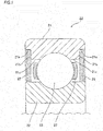
- FIG. 1 is a sectional view of main parts of a rolling bearing 20 in accordance with a first embodiment of the present invention.
- the rolling bearing 20 includes an outer ring 21, an inner ring 22, which is an inner ring part, a plurality of balls 23, which are rolling elements provided between the inner and outer rings, a cage 27 configured to rollably hold the balls 23, and metallic shields 25 having a flat plate shape.
- Inner peripheral surfaces of both axial end portions of the outer ring 21 are provided with large-diameter parts 21a, each of which has a diameter larger than an inner diameter of an inner peripheral surface 21c (in the first embodiment, an inner peripheral surface of a shoulder part) of the outer ring 21, opens outward in an axial direction, and has an axial width greater than an axial width (thickness) of the shield 25.
- the shield 25 has a thin plate shape, like a flat washer having a constant thickness as shown in FIG. 2 .
- a material of the shield 25 for example, zinc, aluminum and magnesium are plated on SPCC.
- an inner diameter of the shield 25 is set so that a labyrinth gap is to be formed between the the inner diameter of the shield 25 and an outer peripheral surface of the inner ring.
- an outer shape surface of the shield 25 is configured by a plurality of circular arcs 25a having the same central angle and equidistantly arranged on a circumference and a plurality of chords 25b connecting the adjacent circular arcs 25a each other.
- the central angles ⁇ of the respective circular arcs 25a are the same and the central angles ⁇ of the respective chords 25b are the same.
- the central angle ⁇ of the circular arc 25a and the central angle ⁇ of the chord 25b are not necessarily required to be the same.
- the central angle ⁇ of the chord 25b is designed greater than the central angle ⁇ of the circular arc 25a, so that a press-fitting area to the large-diameter part 21a of the outer ring 21 is reduced.
- the shield 25 is press-fitted and fixed so as to butt to an axially inner end face 21b of the large-diameter part 21a. That is, the large-diameter part 21a is provided so as to form the axially inner end face 21b for axially positioning the shield 25, and is preferably formed so that a minimum area of the axially inner end face 21b capable of determining a press-fitting position is to be secured.
- the shield 25 is formed to be axially symmetric. Therefore, upon the press-fitting, it is not necessary to distinguish a front surface and a back surface, so that it is possible to easily perform the assembling.
- the shield 25 is configured by the plurality of circular arcs 25a having the same central angle and equidistantly arranged on the circumference and the plurality of chords 25b connecting the adjacent circular arcs 25a each other, the shield can be mounted to the outer ring 21 in any phase and can be easily assembled.
- the press-fitting force, the pulling-out force, a degree of deformation of an outer diameter and the like are changed by the axial width of the shield 25, the number and central angle of the circular arcs and a diameter of the large-diameter part 21a relative to a diameter of the circular arc. Therefore, optimal values of dimensions of the respective parts are preferably set by a test and the like, considering a dimension of the outer ring of the bearing, a pulling-out force to be required, an allowable amount of deformation of an outer shape, and the like.
- An inscribed circle 25c of the respective chords 25b of the shield 25 preferably has a diameter larger than the inner diameter of the inner peripheral surface 21c of the outer ring 21.
- the axially inner end face 21b of the large-diameter part 21a is preferably a flat surface so that a gap is not to be formed between the axially inner end face 21b and the shield 25.
- At least one of edge portions between axial end faces and an outer shape surface of the shield 25 and an edge portion between an axial end face and the large-diameter part 21a of the outer ring 21 is preferably provided with pressing introduction portions 21d, 25d.
- a taper shape, a convex curve-shaped section (curved shape) or a combination thereof can be applied to the pressing introduction portion 21d of the outer ring 21 and the pressing introduction portion 25d of the shield 25.
- taper angles ⁇ 1, ⁇ 2 are preferably 45° or lower (refer to FIG. 4 ).
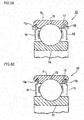
- the pressing introduction portion 21d of the outer ring 21 and the pressing introduction portion 25d of the shield 25 may be formed to have the taper shape or as shown in FIG. 3B , the pressing introduction portion 21d of the outer ring 21 and the pressing introduction portion 25d of the shield 25 may be formed to have the convex curve-shaped section (curved shape).
- a dimension relation of ⁇ B ⁇ ⁇ A ⁇ ⁇ C is preferably satisfied where ⁇ A indicates a diameter at a boundary part between the large-diameter part 21a and the pressing introduction portion 21d of the outer ring 21, ⁇ B indicates a dimeter at a boundary part between the axial end face and the pressing introduction portion 25d of the shield 25 and ⁇ C indicates a diameter of the circular arc 25a of the shield 25, from standpoints of easy press-fitting and secure press-fitting.
- the pressing introduction portion 21d of the outer ring 21 may be formed to have the convex curve-shaped section, and the pressing introduction portion 25d of the shield 25 may be formed to have the taper shape. Since the shield 25 has a small thickness, the pressing introduction portion 25d of the taper shape can be easily machined. Also, the pressing introduction portion 21d of the outer ring 21 having the convex curve-shaped section can be easily machined by grinding, and the shield 25 having the pressing introduction portion 25d of the taper shape can be well inserted.
- the pressing introduction portions 25d of the shield 25 are provided at both the edge portions between both axial end faces and the outer shape surface, so that it is not necessary to distinguish the front surface and back surface of the shield 25 upon the press-fitting and the shield can be easily mounted.
- the chord 25b is also punched from one axial side by a press machine and is then chamfered.
- the pressing introduction portions 25d are formed at the circular arc 25a after the chamfering.
- the shield 25 shown in FIG. 2 has a substantially octagonal shape configured by the eight circular arcs 25a and the eight chords 25b.
- the shield 25 of the present invention is not limited thereto, and may be a substantially polygonal shape of a substantial hexagon or more configured by the six circular arcs 25a and the six chords 25b.
- the inscribed circle 25c of the respective chords 25b of the shield 25 has preferably the diameter greater than the inner diameter of the inner peripheral surface 21c of the outer ring 21.
- the shield 25 shown in FIG. 6 is a substantial hexadecagon configured by the sixteen circular arcs 25a and the sixteen chords 25b where the central angles ⁇ , ⁇ are set so that the appropriate press-fitting area is to be secured and the inscribed circle 25c of the respective chords 25b of the shield 25 has a diameter greater than the inner diameter of the inner peripheral surface 21c of the outer ring 21.
- the central angle ⁇ of the chord 25b is preferably designed greater than the central angle ⁇ of the circular arc 25a.
- the central angle ⁇ of the circular arc 25a is set to 3.5°
- the central angle ⁇ of the chord 25b is set to 19°, so that a sum of the central angles ⁇ , ⁇ of the circular arc 25a and the chord 25b is 22.5°.
- the central angle ⁇ of the circular arc 25a is set within a range of 2 to 7°
- the central angle ⁇ of the chord 25b is set within a range of 15 to 22".
- the shield 25 may be press-fitted to the inner peripheral surface 21c of the outer ring 21 without providing the large-diameter part 21a. Also, in the first embodiment, the example where the shields 25 are provided at both axial sides has been described. However, the shield 25 may be provided only at one axial side.
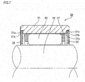
- FIG. 7 is a sectional view of main parts of a rolling bearing 30 in accordance with a second embodiment of the present invention.
- the rolling bearing 30 includes an outer ring 31, a plurality of rollers 33, which are the rolling elements, a cage 37 configured to rollably hold the rollers 33, and metallic shields 35 having a flat plate shape.
- Inner peripheral surfaces of both axial end portions of the outer ring 31 are provided with large-diameter parts 31a, each of which has a diameter larger than an inner diameter of the outer ring 31, opens outward in the axial direction, and has an axial width greater than an axial width (thickness) of the shield 35.
- the shield 35 has a thin plate shape, like a flat washer having a constant thickness as shown in FIG. 2 , and an inner diameter thereof is set so that a labyrinth gap is to be formed between the shield and an outer peripheral surface of a support shaft 32, which is an inner ring part.
- An outer shape surface of the shield 35 is configured by a plurality of circular arcs 35a having the same central angle and equidistantly arranged on a circumference and a plurality of chords 35b connecting the adjacent circular arcs 35a each other.
- the central angles ⁇ of the respective circular arcs 35a are the same and the central angles ⁇ of the respective chords 35b are the same.
- the central angle ⁇ of the circular arc 35a and the central angle ⁇ of the chord 35b are not necessarily required to be the same.
- the central angle ⁇ of the chord 35b is designed greater than the central angle ⁇ of the circular arc 35a, so that a press-fitting area to the large-diameter part 31a of the outer ring 31 is reduced.
- the shield 35 is press-fitted and fixed so as to butt to an axially inner end face 31b of the large-diameter part 31a. That is, the large-diameter part 31a is provided so as to form the axially inner end face 31b for axially positioning the shield 35, and is preferably formed so that a minimum area of the axially inner end face 31b capable of determining a press-fitting position is to be secured.
- the press-fitting force, the pulling-out force, a degree of deformation of an outer diameter and the like are changed by the axial width of the shield 35, the number and central angle of the circular arcs and a diameter of the large-diameter part 31a relative to a diameter of the circular arc. Therefore, optimal values of dimensions of the respective parts are preferably set by a test and the like, considering a dimension of the outer ring of the bearing, a pulling-out force to be required, an allowable amount of deformation of an outer shape, and the like.
- An inscribed circle 35c of the respective chords 35b of the shield 35 preferably has a diameter larger than the inner diameter of the outer ring.
- the axially inner end face 31b of the large-diameter part 31a is preferably a flat surface so that a gap is not to be formed between the axially inner end face and the shield 35.
- the shield 35 may be press-fitted to the inner peripheral surface 31c of the outer ring without providing the large-diameter part 31a. Also, in the second embodiment, the example where the shields 35 are provided at both axial sides has been described. However, the shield 35 may be provided only at one axial side. Also, in the bearing 30 of the second embodiment, the outer peripheral surface of the support shaft 32 equivalent to the inner ring is used as a raceway. However, a rolling bearing having an inner ring is also possible.
- the present invention is not limited to the above embodiments, and can be appropriately modified and improved.
- the outer shape surface of the shield is configured by the plurality of circular arcs and the plurality of chords connecting the adjacent circular arcs each other.
- a V-shaped cutout may also be used.
- the rolling bearing of the present invention can be applied as a support bearing of a ball screw.
Landscapes
- Engineering & Computer Science (AREA)
- General Engineering & Computer Science (AREA)
- Mechanical Engineering (AREA)
- Rolling Contact Bearings (AREA)
- Sealing Using Fluids, Sealing Without Contact, And Removal Of Oil (AREA)
- Sealing Of Bearings (AREA)
Abstract
Description
- The present invention relates to a rolling bearing to which a shield for sealing a bearing inside from a bearing outside is mounted, and particularly, to a mounting technology of the shield.
- In the related art, as a grease lubrication bearing, a rolling bearing to which a metallic shield is mounted so as to keep grease in a bearing and to prevent introduction of foreign matters has been known (for example, refer to Patent Document 1). As an example, a sectional view of main parts of the rolling bearing of the related art is shown in
FIGS. 8A and 8B . A rollingbearing 10 includes anouter ring 11, aninner ring 12, a plurality ofballs 13 provided between the inner andouter rings cage 17 configured to rollably hold theballs 13, andmetallic shields outer ring 11 is formed with metallicshield fixing grooves - Subsequently, a method of mounting the
metallic shields bearing 10 is described. As shown inFIG. 8A , themetallic shield 14 bent in advance is contacted to thegroove 11a. Then, as shown inFIG. 8B , themetallic shield 14 is mounted and fixed to thefixing groove 11a by using swaging deformation with a press machine or the like. Similarly, the othermetallic shield 15 is also mounted and fixed to thefixing groove 11b. - According to the configuration of mounting and fixing the metallic shields, for the secure mounting, it is necessary to provide the metallic shield fixing groove of the outer ring with a groove for forming an outward expanded space from an outer side toward an inner side. However, there is no axial margin for providing the groove at the thin outer ring (the outer ring of which an axial width is narrow), so that it is not possible to mount and fix the metallic shield to the rolling bearing.
- In order to solve the above problem, Patent Document 2 discloses a technology of mounting and fixing a washer-shaped shield to the outer ring by laser welding. However, according to this technology, the cost increases as a result of the laser welding. Also, a shape of a bearing raceway is likely to collapse due to the welding. Therefore, a method of mounting and fixing the washer-shaped shield by press fitting in which a shield outer-diameter surface and an outer ring inner-diameter surface are used as fitting parts is considered. However, when press fitting the shield, particularly, to the thin outer ring (the outer ring having a small radial thickness of which a dimension difference between outer and inner diameters is small), the outer ring is likely to be deformed.
- Also, Patent Document 3 discloses a bearing sealing device in which an outer periphery of a metallic annular plate is provided at six equidistantly spaced parts with concave cutouts for allowing the annular plate to be radially bent and the metallic annular plate is fitted with being bent to a circumferential groove of an outer ring. In this case, however, it is necessary to provide the cutout having a dimension allowing the bending, in correspondence to a radial dimension of an inner wall surface of an outer side of the circumferential groove, which may influence rigidity of the annular plate when used.
-
- Patent Document 1:
JP-A-2001-027253 - Patent Document 2:
JP-A-H11-351263 - Patent Document 3:
JP-A-H07-279979 - The present invention has been made in view of the above situations, and an object thereof is to provide a rolling bearing capable of mounting a metallic shield to even an outer ring having a small width of which an axial width is narrow or an outer ring having a small thickness of which a radial width is narrow.
- The object of the present invention is solved by a rolling bearing comprising an outer ring, an inner ring part, a plurality of rolling elements, a cage configured to rollably hold the plurality of rolling elements, and a shield. An inner peripheral surface of at least one axial end portion of the outer ring is provided with a large-diameter part, which has a diameter larger than an inner diameter of the outer ring, opens outward in an axial direction, and has an axial width greater than an axial width of the shield. An outer shape surface of the shield is configured by a plurality of circular arcs having a same central angle and equidistantly arranged on a circumference and a plurality of chords connecting adjacent circular arcs each other. The shield is press-fitted and fixed to the large-diameter part.
- According to the present invention, since the shield is press-fitted to the bearing, it is possible to mount the metallic shield even to the outer ring having a small width of which am axial width is narrow. Also, the outer-diameter surface of the shield that is to be press-fitted to the bearing is configured by the plurality of circular arcs having the same central angle and equidistantly arranged on the circumference and the plurality of chords connecting the adjacent circular arcs each other. Therefore, since the press-fitting surface does not extend over the entire circumference, a press fitting area is small, so that deformation of the outer ring can be suppressed. Also, since the circular arc portions are equidistantly arranged on the circumference, it is possible to suppress the outer ring from being non-uniformly deformed. Accordingly, it is possible to mount the metallic shield even to the outer ring having a small thickness of which a radial width is narrow.
-
-
FIG. 1 is a sectional view of main parts of a rolling bearing in accordance with a first embodiment of the present invention. -
FIG. 2 depicts a shape of a shield relating to the present invention. -
FIG. 3A is a sectional view of main parts depicting a first example where pressing introduction portions are provided at edge portions between axial end faces and an outer shape surface of the shield and at an edge portion between an axial end face and a large-diameter part of an outer ring, andFIG. 3B is a sectional view of main parts depicting a second example where the pressing introduction portions are provided at the edge portions between the axial end faces and the outer shape surface of the shield and at the edge portion between the axial end face and the large-diameter part of the outer ring. -
FIG. 4 is an enlarged view of main parts depicting a dimension relation of the pressing introduction portions in the first example ofFIG. 3A . -
FIG. 5 is a sectional view of main parts depicting a third example where the pressing introduction portions are provided at the edge portions between the axial end faces and the outer shape surface of the shield and at the edge portion between the axial end face and the large-diameter part of the outer ring. -
FIG. 6 depicts a shape of another shield relating to the present invention. -
FIG. 7 is a sectional view of main parts of a rolling bearing in accordance with a second embodiment of the present invention. -
FIGS. 8A and 8B are sectional views of main parts of a rolling bearing of the related art, illustrating a method of mounting a shield of the related art. - Hereinafter, embodiments of the present invention will be described in detail with reference to the accompanying drawings.
FIG. 1 is a sectional view of main parts of a rolling bearing 20 in accordance with a first embodiment of the present invention. The rollingbearing 20 includes anouter ring 21, aninner ring 22, which is an inner ring part, a plurality ofballs 23, which are rolling elements provided between the inner and outer rings, acage 27 configured to rollably hold theballs 23, andmetallic shields 25 having a flat plate shape. Inner peripheral surfaces of both axial end portions of theouter ring 21 are provided with large-diameter parts 21a, each of which has a diameter larger than an inner diameter of an innerperipheral surface 21c (in the first embodiment, an inner peripheral surface of a shoulder part) of theouter ring 21, opens outward in an axial direction, and has an axial width greater than an axial width (thickness) of theshield 25. - The
shield 25 has a thin plate shape, like a flat washer having a constant thickness as shown inFIG. 2 . As a material of theshield 25, for example, zinc, aluminum and magnesium are plated on SPCC. Also, an inner diameter of theshield 25 is set so that a labyrinth gap is to be formed between the the inner diameter of theshield 25 and an outer peripheral surface of the inner ring. In the meantime, an outer shape surface of theshield 25 is configured by a plurality ofcircular arcs 25a having the same central angle and equidistantly arranged on a circumference and a plurality ofchords 25b connecting the adjacentcircular arcs 25a each other. In the meantime, the central angles α of the respectivecircular arcs 25a are the same and the central angles β of therespective chords 25b are the same. However, the central angle α of thecircular arc 25a and the central angle β of thechord 25b are not necessarily required to be the same. - Also, the central angle β of the
chord 25b is designed greater than the central angle α of thecircular arc 25a, so that a press-fitting area to the large-diameter part 21a of theouter ring 21 is reduced. As a result, when incorporating the rollingbearing 20 into a housing or the like, it is possible to suppress deformation of theouter ring 21 so as not to influence the incorporation. - The
shield 25 is press-fitted and fixed so as to butt to an axiallyinner end face 21b of the large-diameter part 21a. That is, the large-diameter part 21a is provided so as to form the axiallyinner end face 21b for axially positioning theshield 25, and is preferably formed so that a minimum area of the axiallyinner end face 21b capable of determining a press-fitting position is to be secured. Theshield 25 is formed to be axially symmetric. Therefore, upon the press-fitting, it is not necessary to distinguish a front surface and a back surface, so that it is possible to easily perform the assembling. Also, since theshield 25 is configured by the plurality ofcircular arcs 25a having the same central angle and equidistantly arranged on the circumference and the plurality ofchords 25b connecting the adjacentcircular arcs 25a each other, the shield can be mounted to theouter ring 21 in any phase and can be easily assembled. In the meantime, the press-fitting force, the pulling-out force, a degree of deformation of an outer diameter and the like are changed by the axial width of theshield 25, the number and central angle of the circular arcs and a diameter of the large-diameter part 21a relative to a diameter of the circular arc. Therefore, optimal values of dimensions of the respective parts are preferably set by a test and the like, considering a dimension of the outer ring of the bearing, a pulling-out force to be required, an allowable amount of deformation of an outer shape, and the like. - An inscribed
circle 25c of therespective chords 25b of theshield 25 preferably has a diameter larger than the inner diameter of the innerperipheral surface 21c of theouter ring 21. Also, the axiallyinner end face 21b of the large-diameter part 21a is preferably a flat surface so that a gap is not to be formed between the axiallyinner end face 21b and theshield 25. Thereby, it is possible to prevent introduction of foreign matters and grease leakage from a gap between the large-diameter part 21a of the outer ring and a radially outer side of thechord 25b of theshield 25. However, when the gap is small even though it exists, the gap becomes a labyrinth gap, so that it is possible to prevent the introduction of foreign matters and the grease leakage. Therefore, when the gap is inevitably formed, the gap is preferably set as small as possible. - Also, as shown in
FIGS. 3 to 5 , at least one of edge portions between axial end faces and an outer shape surface of theshield 25 and an edge portion between an axial end face and the large-diameter part 21a of theouter ring 21 is preferably provided withpressing introduction portions shield 25 to the large-diameter part 21a of theouter ring 21, it is possible to prevent situations where the edge portions between the axial end faces and the outer shape surface of theshield 25 are cut, foreign matters are generated and an interference is reduced and theshield 25 is thus separated. - Also, a taper shape, a convex curve-shaped section (curved shape) or a combination thereof can be applied to the
pressing introduction portion 21d of theouter ring 21 and thepressing introduction portion 25d of theshield 25. When the taper shape is applied, taper angles θ1, θ2 are preferably 45° or lower (refer toFIG. 4 ). - Specifically, as shown in
FIG. 3A , thepressing introduction portion 21d of theouter ring 21 and thepressing introduction portion 25d of theshield 25 may be formed to have the taper shape or as shown inFIG. 3B , thepressing introduction portion 21d of theouter ring 21 and thepressing introduction portion 25d of theshield 25 may be formed to have the convex curve-shaped section (curved shape). - Also, when the
pressing introduction portion 21d of theouter ring 21 and thepressing introduction portion 25d of theshield 25 are formed to have the taper shape, as shown inFIG. 4 , a dimension relation of φB< φA< φC is preferably satisfied where φA indicates a diameter at a boundary part between the large-diameter part 21a and thepressing introduction portion 21d of theouter ring 21, φB indicates a dimeter at a boundary part between the axial end face and thepressing introduction portion 25d of theshield 25 and φC indicates a diameter of thecircular arc 25a of theshield 25, from standpoints of easy press-fitting and secure press-fitting. - Also, as shown in
FIG. 5 , thepressing introduction portion 21d of theouter ring 21 may be formed to have the convex curve-shaped section, and thepressing introduction portion 25d of theshield 25 may be formed to have the taper shape. Since theshield 25 has a small thickness, thepressing introduction portion 25d of the taper shape can be easily machined. Also, thepressing introduction portion 21d of theouter ring 21 having the convex curve-shaped section can be easily machined by grinding, and theshield 25 having thepressing introduction portion 25d of the taper shape can be well inserted. - Also, the
pressing introduction portions 25d of theshield 25 are provided at both the edge portions between both axial end faces and the outer shape surface, so that it is not necessary to distinguish the front surface and back surface of theshield 25 upon the press-fitting and the shield can be easily mounted. - In the meantime, in order to form the
shield 25 to be axially symmetric and to remove burrs, thechord 25b is also punched from one axial side by a press machine and is then chamfered. Thepressing introduction portions 25d are formed at thecircular arc 25a after the chamfering. - Also, the
shield 25 shown inFIG. 2 has a substantially octagonal shape configured by the eightcircular arcs 25a and the eightchords 25b. However, theshield 25 of the present invention is not limited thereto, and may be a substantially polygonal shape of a substantial hexagon or more configured by the sixcircular arcs 25a and the sixchords 25b. - In any case, it is required that an outer diameter at a mid-point of the
chord 25b is smaller than the inner diameter of the innerperipheral surface 21c of theouter ring 21 and a gap is not generated between thechord 25b and the inner peripheral surface of theouter ring 21. Therefore, as described above, the inscribedcircle 25c of therespective chords 25b of theshield 25 has preferably the diameter greater than the inner diameter of the innerperipheral surface 21c of theouter ring 21. - For example, the
shield 25 shown inFIG. 6 is a substantial hexadecagon configured by the sixteencircular arcs 25a and the sixteenchords 25b where the central angles α, β are set so that the appropriate press-fitting area is to be secured and the inscribedcircle 25c of therespective chords 25b of theshield 25 has a diameter greater than the inner diameter of the innerperipheral surface 21c of theouter ring 21. Also in this case, the central angle β of thechord 25b is preferably designed greater than the central angle α of thecircular arc 25a. - Specifically, the central angle α of the
circular arc 25a is set to 3.5°, the central angle β of thechord 25b is set to 19°, so that a sum of the central angles α, β of thecircular arc 25a and thechord 25b is 22.5°. However, actually, considering a dimension tolerance, the central angle α of thecircular arc 25a is set within a range of 2 to 7°, and the central angle β of thechord 25b is set within a range of 15 to 22". - In the meantime, as a pressing interference, 2µm is set. However, since the dimension tolerance of the
shield 25 is ±35µm and the dimension tolerance of the large-diameter part 21a of theouter ring 21 is ±25µm, the actual pressing interference is 2 to 62µm. - Also, in the first embodiment, the example where the
outer ring 21 is provided with the large-diameter part 21a has been described. However, theshield 25 may be press-fitted to the innerperipheral surface 21c of theouter ring 21 without providing the large-diameter part 21a. Also, in the first embodiment, the example where theshields 25 are provided at both axial sides has been described. However, theshield 25 may be provided only at one axial side. -
FIG. 7 is a sectional view of main parts of a rollingbearing 30 in accordance with a second embodiment of the present invention. As shown inFIG. 7 , the rollingbearing 30 includes anouter ring 31, a plurality ofrollers 33, which are the rolling elements, acage 37 configured to rollably hold therollers 33, andmetallic shields 35 having a flat plate shape. Inner peripheral surfaces of both axial end portions of theouter ring 31 are provided with large-diameter parts 31a, each of which has a diameter larger than an inner diameter of theouter ring 31, opens outward in the axial direction, and has an axial width greater than an axial width (thickness) of theshield 35. - The
shield 35 has a thin plate shape, like a flat washer having a constant thickness as shown inFIG. 2 , and an inner diameter thereof is set so that a labyrinth gap is to be formed between the shield and an outer peripheral surface of asupport shaft 32, which is an inner ring part. An outer shape surface of theshield 35 is configured by a plurality ofcircular arcs 35a having the same central angle and equidistantly arranged on a circumference and a plurality ofchords 35b connecting the adjacentcircular arcs 35a each other. In the meantime, the central angles α of the respectivecircular arcs 35a are the same and the central angles β of therespective chords 35b are the same. However, the central angle α of thecircular arc 35a and the central angle β of thechord 35b are not necessarily required to be the same. - Also, the central angle β of the
chord 35b is designed greater than the central angle α of thecircular arc 35a, so that a press-fitting area to the large-diameter part 31a of theouter ring 31 is reduced. As a result, when incorporating the rollingbearing 30 into a housing or the like, it is possible to suppress deformation of theouter ring 31 so as not to influence the incorporation. - The
shield 35 is press-fitted and fixed so as to butt to an axiallyinner end face 31b of the large-diameter part 31a. That is, the large-diameter part 31a is provided so as to form the axiallyinner end face 31b for axially positioning theshield 35, and is preferably formed so that a minimum area of the axiallyinner end face 31b capable of determining a press-fitting position is to be secured. In the meantime, the press-fitting force, the pulling-out force, a degree of deformation of an outer diameter and the like are changed by the axial width of theshield 35, the number and central angle of the circular arcs and a diameter of the large-diameter part 31a relative to a diameter of the circular arc. Therefore, optimal values of dimensions of the respective parts are preferably set by a test and the like, considering a dimension of the outer ring of the bearing, a pulling-out force to be required, an allowable amount of deformation of an outer shape, and the like. - An inscribed
circle 35c of therespective chords 35b of theshield 35 preferably has a diameter larger than the inner diameter of the outer ring. Also, the axiallyinner end face 31b of the large-diameter part 31a is preferably a flat surface so that a gap is not to be formed between the axially inner end face and theshield 35. Thereby, it is possible to prevent introduction of foreign matters and grease leakage from a gap between the large-diameter part 31a of the outer ring and a radially outer side of thechord 35b of theshield 35. However, when the gap is small even though it exists, the gap becomes a labyrinth gap, so that it is possible to prevent the introduction of foreign matters and the grease leakage. Therefore, when the gap is inevitably formed, the gap is preferably set as small as possible. - In the second embodiment, the example where the
outer ring 31 is provided with the large-diameter part 31a has been described. However, theshield 35 may be press-fitted to the innerperipheral surface 31c of the outer ring without providing the large-diameter part 31a. Also, in the second embodiment, the example where theshields 35 are provided at both axial sides has been described. However, theshield 35 may be provided only at one axial side. Also, in the bearing 30 of the second embodiment, the outer peripheral surface of thesupport shaft 32 equivalent to the inner ring is used as a raceway. However, a rolling bearing having an inner ring is also possible. - The present invention is not limited to the above embodiments, and can be appropriately modified and improved. For example, in the above embodiments, the outer shape surface of the shield is configured by the plurality of circular arcs and the plurality of chords connecting the adjacent circular arcs each other. However, instead of the chord, a V-shaped cutout may also be used. Also, the rolling bearing of the present invention can be applied as a support bearing of a ball screw.
- As described above, the present disclosure discloses following matters:
- (1) A rolling bearing comprising:
- an outer ring;
- an inner ring part;
- a plurality of rolling elements;
- a cage configured to rollably hold the plurality of rolling elements, and
- a shield,
- wherein an inner peripheral surface of at least one axial end portion of the outer ring is provided with a large-diameter part, which has a diameter larger than an inner diameter of the outer ring, opens outward in an axial direction, and has an axial width greater than an axial width of the shield,
- wherein an outer shape surface of the shield is configured by a plurality of circular arcs having a same central angle and equidistantly arranged on a circumference and a plurality of chords connecting adjacent circular arcs each other, and
- wherein the shield is press-fitted and fixed to the large-diameter part.
- (2) The rolling bearing according to (1),
wherein a central angle of the chord is greater than a central angle of the circular arc. - (3) The rolling bearing according to (1) or (2),
wherein at least one of (a) an edge portion between an axial end face and the outer shape surface of the shield and (b) an edge portion between an axial end face and the large-diameter part of the outer ring is provided with a pressing introduction portion. - (4) The rolling bearing according to (3),
wherein the pressing introduction portion has a taper shape or a convex curve-shaped section. - (5) The rolling bearing according to (3),
wherein both (a) the edge portion between the axial end face and the outer shape surface of the shield and (b) the edge portion between the axial end face and the large-diameter part of the outer ring are formed with the pressing introduction portion having a taper shape, and
wherein when a diameter at a boundary part between the large-diameter part and the pressing introduction portion of the outer ring is φA, a dimeter at a boundary part between the axial end face and the pressing introduction portion of the shield is φB, and a diameter of the circular arc of the shield is φC, a dimension relation of φB< φA< φC is satisfied. - (6) The rolling bearing according to (3),
wherein the edge portion between the axial end face and the large-diameter part of the outer ring is formed with the pressing introduction portion having a convex curve-shaped section, and
wherein the edge portion between the axial end face and the outer shape surface of the shield is formed with the pressing introduction portion having a taper shape. - (7) The rolling bearing according to one of (3) to (6),
wherein both edge portions between both axial end faces and the outer shape surface of the shield are provided with the pressing introduction portion. - (8) The rolling bearing according to one of (1) to (7),
wherein a labyrinth gap is formed between an inner-diameter surface of the shield and an outer shape surface of the inner ring part. - (9) The rolling bearing according to one of (1) to (8),
wherein the large-diameter part of the outer ring is formed with an axially inner end face for axially positioning the shield. - The subject application is based on Japanese Patent Application No.
2017-031662 filed on February 23, 2017 -
- 10, 20, 30: rolling bearing
- 11, 21, 31: outer ring
- 21a, 31a: large-diameter part
- 21b, 31b: axially inner end face
- 21c, 31c: inner peripheral surface
- 21d, 25d: pressing introduction portion
- 12, 22: inner ring (inner ring part)
- 32: support shaft (inner ring part)
- 13, 23, 33: rolling element
- 14, 15, 25, 35: shield
- 25a, 35a: circular arc
- 25b, 35b: chord
- 25c, 35c: inscribed circle of chord
- 27: cage
- α: central angle of circular arc
- β: central angle of chord
Claims (9)
- A rolling bearing comprising:an outer ring;an inner ring part;a plurality of rolling elements;a cage configured to rollably hold the plurality of rolling elements, anda shield,wherein an inner peripheral surface of at least one axial end portion of the outer ring is provided with a large-diameter part, which has a diameter larger than an inner diameter of the outer ring, opens outward in an axial direction, and has an axial width greater than an axial width of the shield,wherein an outer shape surface of the shield is configured by a plurality of circular arcs having a same central angle and equidistantly arranged on a circumference and a plurality of chords connecting adjacent circular arcs each other, andwherein the shield is press-fitted and fixed to the large-diameter part.
- The rolling bearing according to claim 1,
wherein a central angle of the chord is greater than a central angle of the circular arc. - The rolling bearing according to claim 1 or 2,
wherein at least one of (a) an edge portion between an axial end face and the outer shape surface of the shield and (b) an edge portion between an axial end face and the large-diameter part of the outer ring is provided with a pressing introduction portion. - The rolling bearing according to claim 3,
wherein the pressing introduction portion has a taper shape or a convex curve-shaped section. - The rolling bearing according to claim 3,
wherein both (a) the edge portion between the axial end face and the outer shape surface of the shield and (b) the edge portion between the axial end face and the large-diameter part of the outer ring are formed with the pressing introduction portion having a taper shape, and
wherein when a diameter at a boundary part between the large-diameter part and the pressing introduction portion of the outer ring is φA, a dimeter at a boundary part between the axial end face and the pressing introduction portion of the shield is φB, and a diameter of the circular arc of the shield is φC, a dimension relation of φB< φA< φC is satisfied. - The rolling bearing according to claim 3,
wherein the edge portion between the axial end face and the large-diameter part of the outer ring is formed with the pressing introduction portion having a convex curve-shaped section, and
wherein the edge portion between the axial end face and the outer shape surface of the shield is formed with the pressing introduction portion having a taper shape. - The rolling bearing according to one of claims 3 to 6,
wherein both edge portions between both axial end faces and the outer shape surface of the shield are provided with the pressing introduction portion. - The rolling bearing according to one of claims 1 to 7,
wherein a labyrinth gap is formed between an inner-diameter surface of the shield and an outer shape surface of the inner ring part. - The rolling bearing according to one of claims 1 to 8,
wherein the large-diameter part of the outer ring is formed with an axially inner end face for axially positioning the shield.
Applications Claiming Priority (2)
| Application Number | Priority Date | Filing Date | Title |
|---|---|---|---|
| JP2017031662 | 2017-02-23 | ||
| PCT/JP2018/006824 WO2018155659A1 (en) | 2017-02-23 | 2018-02-23 | Roller bearing |
Publications (3)
| Publication Number | Publication Date |
|---|---|
| EP3421828A1 true EP3421828A1 (en) | 2019-01-02 |
| EP3421828A4 EP3421828A4 (en) | 2019-05-01 |
| EP3421828B1 EP3421828B1 (en) | 2020-01-22 |
Family
ID=63252807
Family Applications (1)
| Application Number | Title | Priority Date | Filing Date |
|---|---|---|---|
| EP18757179.9A Active EP3421828B1 (en) | 2017-02-23 | 2018-02-23 | Roller bearing |
Country Status (5)
| Country | Link |
|---|---|
| US (1) | US10584742B2 (en) |
| EP (1) | EP3421828B1 (en) |
| JP (1) | JP6376316B1 (en) |
| CN (1) | CN110337550B (en) |
| WO (1) | WO2018155659A1 (en) |
Families Citing this family (2)
| Publication number | Priority date | Publication date | Assignee | Title |
|---|---|---|---|---|
| CN112780691B (en) * | 2020-12-02 | 2022-10-21 | 河北天马轴承制造有限公司 | Balanced support bearing |
| DE102021124846A1 (en) | 2021-09-27 | 2023-03-30 | Schaeffler Technologies AG & Co. KG | Bearing arrangement for an agricultural machine |
Family Cites Families (27)
| Publication number | Priority date | Publication date | Assignee | Title |
|---|---|---|---|---|
| SE147456C1 (en) * | ||||
| US2902300A (en) * | 1956-10-29 | 1959-09-01 | Marlin Rockwell Corp | Shield for rotatable members |
| US3597030A (en) * | 1969-04-22 | 1971-08-03 | Skf Svenska Kullagerfab Ab | Sealing device for rolling bearings |
| JPS58112733U (en) * | 1982-01-26 | 1983-08-02 | エヌ・テ−・エヌ東洋ベアリング株式会社 | Shield plate for rolling bearings |
| JPH0473659U (en) * | 1990-11-07 | 1992-06-29 | ||
| JPH06337016A (en) * | 1993-05-28 | 1994-12-06 | Nippon Seiko Kk | Corrosion resistant rolling bearing |
| JP3905138B2 (en) * | 1994-04-05 | 2007-04-18 | 株式会社ジェイテクト | Bearing sealing device |
| JPH08135667A (en) * | 1994-11-14 | 1996-05-31 | Nippon Seiko Kk | Sealing device for rolling bearings |
| US5470158A (en) * | 1994-12-29 | 1995-11-28 | The Torrington Company | Seal for rolling bearings |
| JPH08240228A (en) * | 1995-03-06 | 1996-09-17 | Nippon Seiko Kk | Sealing device for rolling bearings |
| DE29616079U1 (en) * | 1996-09-16 | 1996-10-31 | Skf Gmbh, 97421 Schweinfurt | roller bearing |
| JP3695127B2 (en) * | 1997-04-16 | 2005-09-14 | 日本精工株式会社 | Rolling bearing with sealing plate |
| US20020191877A1 (en) * | 1997-04-16 | 2002-12-19 | Hironori Suzuki | Rolling bearing unit with shield plate |
| JP2990204B2 (en) * | 1998-01-30 | 1999-12-13 | エスアイアイ・マイクロデバイス株式会社 | Rolling bearing, swing arm, rotating body device, and method of manufacturing rolling bearing |
| JPH11351264A (en) * | 1998-06-04 | 1999-12-24 | Nok Corp | Sealing device |
| JPH11351263A (en) | 1998-06-05 | 1999-12-24 | Nippon Seiko Kk | Rolling bearing |
| JP2001027253A (en) | 1999-07-14 | 2001-01-30 | Nsk Ltd | Rolling bearing |
| JP3848825B2 (en) * | 2000-09-14 | 2006-11-22 | 内山工業株式会社 | Bearing seal mounting structure |
| US7287910B2 (en) * | 2001-09-03 | 2007-10-30 | Ntn Corporation | Angular ball bearing and rolling bearing |
| JP2003074491A (en) * | 2001-09-04 | 2003-03-12 | Nsk Ltd | Water pump seal device, water pump rotation support device, and water pump |
| EP1450058B1 (en) * | 2003-02-18 | 2008-05-14 | JTEKT Corporation | Rolling bearing with ring made of ceramics |
| JP2008057635A (en) * | 2006-08-30 | 2008-03-13 | Jtekt Corp | Sealing device for rolling bearing |
| JP2011256966A (en) * | 2010-06-10 | 2011-12-22 | Seiko Instruments Inc | Rolling bearing, bearing device and information recording and reproducing device |
| JP6331754B2 (en) * | 2013-07-09 | 2018-05-30 | 日本精工株式会社 | Ball bearing with seal ring |
| DE202014001654U1 (en) * | 2014-02-22 | 2015-05-26 | Oerlikon Leybold Vacuum Gmbh | vacuum equipment |
| CN204739098U (en) * | 2015-06-23 | 2015-11-04 | 瓦房店爱国轴承研究院有限公司 | Bearing seal structure of constituteing vacuum seal chamber by two spring leafs |
| JP2017031662A (en) | 2015-07-31 | 2017-02-09 | 玄 太田 | Water sprinkling snow extinguishing device |
-
2018
- 2018-02-23 CN CN201880014325.1A patent/CN110337550B/en active Active
- 2018-02-23 WO PCT/JP2018/006824 patent/WO2018155659A1/en not_active Ceased
- 2018-02-23 EP EP18757179.9A patent/EP3421828B1/en active Active
- 2018-02-23 JP JP2018527253A patent/JP6376316B1/en active Active
- 2018-02-23 US US16/079,844 patent/US10584742B2/en active Active
Also Published As
| Publication number | Publication date |
|---|---|
| WO2018155659A1 (en) | 2018-08-30 |
| EP3421828B1 (en) | 2020-01-22 |
| US20190360523A1 (en) | 2019-11-28 |
| JP6376316B1 (en) | 2018-08-22 |
| JPWO2018155659A1 (en) | 2019-02-28 |
| EP3421828A4 (en) | 2019-05-01 |
| US10584742B2 (en) | 2020-03-10 |
| CN110337550A (en) | 2019-10-15 |
| CN110337550B (en) | 2020-11-24 |
Similar Documents
| Publication | Publication Date | Title |
|---|---|---|
| US8770854B2 (en) | Rolling element cage | |
| CN104395628B (en) | Rolling bearing unit with mounting plate and method for its manufacture | |
| US10655672B2 (en) | Method and device for producing an angular contact roller bearing | |
| EP3176449B1 (en) | Thrust bearing and manufacturing method for same | |
| EP3421828B1 (en) | Roller bearing | |
| US20200370594A1 (en) | Rolling bearing attachment structure | |
| EP2975278B1 (en) | Rolling bearing and method for manufacturing such a rolling bearing | |
| US8864386B2 (en) | Roller bearing and cage for a roller bearing | |
| US20160017922A1 (en) | Rolling bearing comprising a housing having two parts and method for manufacturing and installing such a bearing | |
| EP2500592A1 (en) | Sealing device, notably for a rolling bearing | |
| JP6064783B2 (en) | Rolling bearing | |
| US10753402B2 (en) | Bearing assembly and bearing cage | |
| WO2018056000A1 (en) | Bearing device for axle | |
| JP2017223253A (en) | Manufacturing method of wheel bearing device | |
| US12169001B2 (en) | Sensor bearing unit with improved breaking torque and method of manufacturing thereof | |
| US9670960B2 (en) | Radial rolling bearing assembly with connector sleeve | |
| US20250043827A1 (en) | Wheel hub unit | |
| JP2020046061A (en) | Holder for conical roller bearing and conical roller bearing | |
| US10704601B2 (en) | Bearing assembly | |
| JP2007309419A (en) | Rolling bearing device | |
| JP2017145895A (en) | Fitting member and bearing device provided with the same | |
| JP6706468B2 (en) | Sealing device | |
| JP2007263212A (en) | Tapered roller bearing | |
| JP2023030912A (en) | rolling bearing | |
| JP2015045395A (en) | Assembling method of rolling bearing |
Legal Events
| Date | Code | Title | Description |
|---|---|---|---|
| STAA | Information on the status of an ep patent application or granted ep patent |
Free format text: STATUS: THE INTERNATIONAL PUBLICATION HAS BEEN MADE |
|
| PUAI | Public reference made under article 153(3) epc to a published international application that has entered the european phase |
Free format text: ORIGINAL CODE: 0009012 |
|
| STAA | Information on the status of an ep patent application or granted ep patent |
Free format text: STATUS: REQUEST FOR EXAMINATION WAS MADE |
|
| 17P | Request for examination filed |
Effective date: 20180926 |
|
| AK | Designated contracting states |
Kind code of ref document: A1 Designated state(s): AL AT BE BG CH CY CZ DE DK EE ES FI FR GB GR HR HU IE IS IT LI LT LU LV MC MK MT NL NO PL PT RO RS SE SI SK SM TR |
|
| AX | Request for extension of the european patent |
Extension state: BA ME |
|
| A4 | Supplementary search report drawn up and despatched |
Effective date: 20190328 |
|
| RIC1 | Information provided on ipc code assigned before grant |
Ipc: F16C 19/06 20060101ALI20190322BHEP Ipc: F16C 33/58 20060101ALI20190322BHEP Ipc: F16C 33/78 20060101AFI20190322BHEP Ipc: F16J 15/447 20060101ALI20190322BHEP |
|
| RIC1 | Information provided on ipc code assigned before grant |
Ipc: F16J 15/447 20060101ALI20190426BHEP Ipc: F16C 33/58 20060101ALI20190426BHEP Ipc: F16C 33/78 20060101AFI20190426BHEP Ipc: F16C 19/06 20060101ALI20190426BHEP |
|
| GRAJ | Information related to disapproval of communication of intention to grant by the applicant or resumption of examination proceedings by the epo deleted |
Free format text: ORIGINAL CODE: EPIDOSDIGR1 |
|
| GRAP | Despatch of communication of intention to grant a patent |
Free format text: ORIGINAL CODE: EPIDOSNIGR1 |
|
| GRAP | Despatch of communication of intention to grant a patent |
Free format text: ORIGINAL CODE: EPIDOSNIGR1 |
|
| STAA | Information on the status of an ep patent application or granted ep patent |
Free format text: STATUS: GRANT OF PATENT IS INTENDED |
|
| DAV | Request for validation of the european patent (deleted) | ||
| DAX | Request for extension of the european patent (deleted) | ||
| INTG | Intention to grant announced |
Effective date: 20190925 |
|
| GRAS | Grant fee paid |
Free format text: ORIGINAL CODE: EPIDOSNIGR3 |
|
| GRAA | (expected) grant |
Free format text: ORIGINAL CODE: 0009210 |
|
| STAA | Information on the status of an ep patent application or granted ep patent |
Free format text: STATUS: THE PATENT HAS BEEN GRANTED |
|
| AK | Designated contracting states |
Kind code of ref document: B1 Designated state(s): AL AT BE BG CH CY CZ DE DK EE ES FI FR GB GR HR HU IE IS IT LI LT LU LV MC MK MT NL NO PL PT RO RS SE SI SK SM TR |
|
| REG | Reference to a national code |
Ref country code: GB Ref legal event code: FG4D |
|
| REG | Reference to a national code |
Ref country code: CH Ref legal event code: EP |
|
| REG | Reference to a national code |
Ref country code: AT Ref legal event code: REF Ref document number: 1227093 Country of ref document: AT Kind code of ref document: T Effective date: 20200215 |
|
| REG | Reference to a national code |
Ref country code: IE Ref legal event code: FG4D |
|
| REG | Reference to a national code |
Ref country code: DE Ref legal event code: R096 Ref document number: 602018002139 Country of ref document: DE |
|
| REG | Reference to a national code |
Ref country code: NL Ref legal event code: MP Effective date: 20200122 |
|
| REG | Reference to a national code |
Ref country code: LT Ref legal event code: MG4D |
|
| PG25 | Lapsed in a contracting state [announced via postgrant information from national office to epo] |
Ref country code: PT Free format text: LAPSE BECAUSE OF FAILURE TO SUBMIT A TRANSLATION OF THE DESCRIPTION OR TO PAY THE FEE WITHIN THE PRESCRIBED TIME-LIMIT Effective date: 20200614 Ref country code: RS Free format text: LAPSE BECAUSE OF FAILURE TO SUBMIT A TRANSLATION OF THE DESCRIPTION OR TO PAY THE FEE WITHIN THE PRESCRIBED TIME-LIMIT Effective date: 20200122 Ref country code: FI Free format text: LAPSE BECAUSE OF FAILURE TO SUBMIT A TRANSLATION OF THE DESCRIPTION OR TO PAY THE FEE WITHIN THE PRESCRIBED TIME-LIMIT Effective date: 20200122 Ref country code: NO Free format text: LAPSE BECAUSE OF FAILURE TO SUBMIT A TRANSLATION OF THE DESCRIPTION OR TO PAY THE FEE WITHIN THE PRESCRIBED TIME-LIMIT Effective date: 20200422 Ref country code: NL Free format text: LAPSE BECAUSE OF FAILURE TO SUBMIT A TRANSLATION OF THE DESCRIPTION OR TO PAY THE FEE WITHIN THE PRESCRIBED TIME-LIMIT Effective date: 20200122 |
|
| PG25 | Lapsed in a contracting state [announced via postgrant information from national office to epo] |
Ref country code: BG Free format text: LAPSE BECAUSE OF FAILURE TO SUBMIT A TRANSLATION OF THE DESCRIPTION OR TO PAY THE FEE WITHIN THE PRESCRIBED TIME-LIMIT Effective date: 20200422 Ref country code: HR Free format text: LAPSE BECAUSE OF FAILURE TO SUBMIT A TRANSLATION OF THE DESCRIPTION OR TO PAY THE FEE WITHIN THE PRESCRIBED TIME-LIMIT Effective date: 20200122 Ref country code: LV Free format text: LAPSE BECAUSE OF FAILURE TO SUBMIT A TRANSLATION OF THE DESCRIPTION OR TO PAY THE FEE WITHIN THE PRESCRIBED TIME-LIMIT Effective date: 20200122 Ref country code: SE Free format text: LAPSE BECAUSE OF FAILURE TO SUBMIT A TRANSLATION OF THE DESCRIPTION OR TO PAY THE FEE WITHIN THE PRESCRIBED TIME-LIMIT Effective date: 20200122 Ref country code: IS Free format text: LAPSE BECAUSE OF FAILURE TO SUBMIT A TRANSLATION OF THE DESCRIPTION OR TO PAY THE FEE WITHIN THE PRESCRIBED TIME-LIMIT Effective date: 20200522 Ref country code: GR Free format text: LAPSE BECAUSE OF FAILURE TO SUBMIT A TRANSLATION OF THE DESCRIPTION OR TO PAY THE FEE WITHIN THE PRESCRIBED TIME-LIMIT Effective date: 20200423 |
|
| REG | Reference to a national code |
Ref country code: DE Ref legal event code: R097 Ref document number: 602018002139 Country of ref document: DE |
|
| REG | Reference to a national code |
Ref country code: BE Ref legal event code: MM Effective date: 20200229 |
|
| PG25 | Lapsed in a contracting state [announced via postgrant information from national office to epo] |
Ref country code: LU Free format text: LAPSE BECAUSE OF NON-PAYMENT OF DUE FEES Effective date: 20200223 Ref country code: LT Free format text: LAPSE BECAUSE OF FAILURE TO SUBMIT A TRANSLATION OF THE DESCRIPTION OR TO PAY THE FEE WITHIN THE PRESCRIBED TIME-LIMIT Effective date: 20200122 Ref country code: CZ Free format text: LAPSE BECAUSE OF FAILURE TO SUBMIT A TRANSLATION OF THE DESCRIPTION OR TO PAY THE FEE WITHIN THE PRESCRIBED TIME-LIMIT Effective date: 20200122 Ref country code: DK Free format text: LAPSE BECAUSE OF FAILURE TO SUBMIT A TRANSLATION OF THE DESCRIPTION OR TO PAY THE FEE WITHIN THE PRESCRIBED TIME-LIMIT Effective date: 20200122 Ref country code: RO Free format text: LAPSE BECAUSE OF FAILURE TO SUBMIT A TRANSLATION OF THE DESCRIPTION OR TO PAY THE FEE WITHIN THE PRESCRIBED TIME-LIMIT Effective date: 20200122 Ref country code: SM Free format text: LAPSE BECAUSE OF FAILURE TO SUBMIT A TRANSLATION OF THE DESCRIPTION OR TO PAY THE FEE WITHIN THE PRESCRIBED TIME-LIMIT Effective date: 20200122 Ref country code: EE Free format text: LAPSE BECAUSE OF FAILURE TO SUBMIT A TRANSLATION OF THE DESCRIPTION OR TO PAY THE FEE WITHIN THE PRESCRIBED TIME-LIMIT Effective date: 20200122 Ref country code: MC Free format text: LAPSE BECAUSE OF FAILURE TO SUBMIT A TRANSLATION OF THE DESCRIPTION OR TO PAY THE FEE WITHIN THE PRESCRIBED TIME-LIMIT Effective date: 20200122 Ref country code: ES Free format text: LAPSE BECAUSE OF FAILURE TO SUBMIT A TRANSLATION OF THE DESCRIPTION OR TO PAY THE FEE WITHIN THE PRESCRIBED TIME-LIMIT Effective date: 20200122 Ref country code: SK Free format text: LAPSE BECAUSE OF FAILURE TO SUBMIT A TRANSLATION OF THE DESCRIPTION OR TO PAY THE FEE WITHIN THE PRESCRIBED TIME-LIMIT Effective date: 20200122 |
|
| REG | Reference to a national code |
Ref country code: AT Ref legal event code: MK05 Ref document number: 1227093 Country of ref document: AT Kind code of ref document: T Effective date: 20200122 |
|
| PLBE | No opposition filed within time limit |
Free format text: ORIGINAL CODE: 0009261 |
|
| STAA | Information on the status of an ep patent application or granted ep patent |
Free format text: STATUS: NO OPPOSITION FILED WITHIN TIME LIMIT |
|
| 26N | No opposition filed |
Effective date: 20201023 |
|
| PG25 | Lapsed in a contracting state [announced via postgrant information from national office to epo] |
Ref country code: AT Free format text: LAPSE BECAUSE OF FAILURE TO SUBMIT A TRANSLATION OF THE DESCRIPTION OR TO PAY THE FEE WITHIN THE PRESCRIBED TIME-LIMIT Effective date: 20200122 Ref country code: IT Free format text: LAPSE BECAUSE OF FAILURE TO SUBMIT A TRANSLATION OF THE DESCRIPTION OR TO PAY THE FEE WITHIN THE PRESCRIBED TIME-LIMIT Effective date: 20200122 Ref country code: IE Free format text: LAPSE BECAUSE OF NON-PAYMENT OF DUE FEES Effective date: 20200223 |
|
| PG25 | Lapsed in a contracting state [announced via postgrant information from national office to epo] |
Ref country code: BE Free format text: LAPSE BECAUSE OF NON-PAYMENT OF DUE FEES Effective date: 20200229 Ref country code: PL Free format text: LAPSE BECAUSE OF FAILURE TO SUBMIT A TRANSLATION OF THE DESCRIPTION OR TO PAY THE FEE WITHIN THE PRESCRIBED TIME-LIMIT Effective date: 20200122 Ref country code: SI Free format text: LAPSE BECAUSE OF FAILURE TO SUBMIT A TRANSLATION OF THE DESCRIPTION OR TO PAY THE FEE WITHIN THE PRESCRIBED TIME-LIMIT Effective date: 20200122 |
|
| PG25 | Lapsed in a contracting state [announced via postgrant information from national office to epo] |
Ref country code: CH Free format text: LAPSE BECAUSE OF NON-PAYMENT OF DUE FEES Effective date: 20210228 Ref country code: LI Free format text: LAPSE BECAUSE OF NON-PAYMENT OF DUE FEES Effective date: 20210228 |
|
| PG25 | Lapsed in a contracting state [announced via postgrant information from national office to epo] |
Ref country code: TR Free format text: LAPSE BECAUSE OF FAILURE TO SUBMIT A TRANSLATION OF THE DESCRIPTION OR TO PAY THE FEE WITHIN THE PRESCRIBED TIME-LIMIT Effective date: 20200122 Ref country code: MT Free format text: LAPSE BECAUSE OF FAILURE TO SUBMIT A TRANSLATION OF THE DESCRIPTION OR TO PAY THE FEE WITHIN THE PRESCRIBED TIME-LIMIT Effective date: 20200122 Ref country code: CY Free format text: LAPSE BECAUSE OF FAILURE TO SUBMIT A TRANSLATION OF THE DESCRIPTION OR TO PAY THE FEE WITHIN THE PRESCRIBED TIME-LIMIT Effective date: 20200122 |
|
| PG25 | Lapsed in a contracting state [announced via postgrant information from national office to epo] |
Ref country code: MK Free format text: LAPSE BECAUSE OF FAILURE TO SUBMIT A TRANSLATION OF THE DESCRIPTION OR TO PAY THE FEE WITHIN THE PRESCRIBED TIME-LIMIT Effective date: 20200122 Ref country code: AL Free format text: LAPSE BECAUSE OF FAILURE TO SUBMIT A TRANSLATION OF THE DESCRIPTION OR TO PAY THE FEE WITHIN THE PRESCRIBED TIME-LIMIT Effective date: 20200122 |
|
| PGFP | Annual fee paid to national office [announced via postgrant information from national office to epo] |
Ref country code: FR Payment date: 20251231 Year of fee payment: 9 |
|
| PGFP | Annual fee paid to national office [announced via postgrant information from national office to epo] |
Ref country code: GB Payment date: 20260106 Year of fee payment: 9 |
|
| PGFP | Annual fee paid to national office [announced via postgrant information from national office to epo] |
Ref country code: DE Payment date: 20260102 Year of fee payment: 9 |