EP3421800A1 - Screw compressor and refrigeration cycle device - Google Patents
Screw compressor and refrigeration cycle device Download PDFInfo
- Publication number
- EP3421800A1 EP3421800A1 EP16891410.9A EP16891410A EP3421800A1 EP 3421800 A1 EP3421800 A1 EP 3421800A1 EP 16891410 A EP16891410 A EP 16891410A EP 3421800 A1 EP3421800 A1 EP 3421800A1
- Authority
- EP
- European Patent Office
- Prior art keywords
- discharge port
- port valve
- screw compressor
- discharge
- stepped shape
- Prior art date
- Legal status (The legal status is an assumption and is not a legal conclusion. Google has not performed a legal analysis and makes no representation as to the accuracy of the status listed.)
- Granted
Links
Images





Classifications
-
- F—MECHANICAL ENGINEERING; LIGHTING; HEATING; WEAPONS; BLASTING
- F04—POSITIVE - DISPLACEMENT MACHINES FOR LIQUIDS; PUMPS FOR LIQUIDS OR ELASTIC FLUIDS
- F04C—ROTARY-PISTON, OR OSCILLATING-PISTON, POSITIVE-DISPLACEMENT MACHINES FOR LIQUIDS; ROTARY-PISTON, OR OSCILLATING-PISTON, POSITIVE-DISPLACEMENT PUMPS
- F04C18/00—Rotary-piston pumps specially adapted for elastic fluids
- F04C18/08—Rotary-piston pumps specially adapted for elastic fluids of intermeshing-engagement type, i.e. with engagement of co-operating members similar to that of toothed gearing
- F04C18/12—Rotary-piston pumps specially adapted for elastic fluids of intermeshing-engagement type, i.e. with engagement of co-operating members similar to that of toothed gearing of other than internal-axis type
- F04C18/14—Rotary-piston pumps specially adapted for elastic fluids of intermeshing-engagement type, i.e. with engagement of co-operating members similar to that of toothed gearing of other than internal-axis type with toothed rotary pistons
- F04C18/16—Rotary-piston pumps specially adapted for elastic fluids of intermeshing-engagement type, i.e. with engagement of co-operating members similar to that of toothed gearing of other than internal-axis type with toothed rotary pistons with helical teeth, e.g. chevron-shaped, screw type
-
- F—MECHANICAL ENGINEERING; LIGHTING; HEATING; WEAPONS; BLASTING
- F04—POSITIVE - DISPLACEMENT MACHINES FOR LIQUIDS; PUMPS FOR LIQUIDS OR ELASTIC FLUIDS
- F04C—ROTARY-PISTON, OR OSCILLATING-PISTON, POSITIVE-DISPLACEMENT MACHINES FOR LIQUIDS; ROTARY-PISTON, OR OSCILLATING-PISTON, POSITIVE-DISPLACEMENT PUMPS
- F04C18/00—Rotary-piston pumps specially adapted for elastic fluids
- F04C18/48—Rotary-piston pumps with non-parallel axes of movement of co-operating members
- F04C18/50—Rotary-piston pumps with non-parallel axes of movement of co-operating members the axes being arranged at an angle of 90 degrees
- F04C18/52—Rotary-piston pumps with non-parallel axes of movement of co-operating members the axes being arranged at an angle of 90 degrees of intermeshing engagement type, i.e. with engagement of co-operating members similar to that of toothed gearing
-
- F—MECHANICAL ENGINEERING; LIGHTING; HEATING; WEAPONS; BLASTING
- F04—POSITIVE - DISPLACEMENT MACHINES FOR LIQUIDS; PUMPS FOR LIQUIDS OR ELASTIC FLUIDS
- F04C—ROTARY-PISTON, OR OSCILLATING-PISTON, POSITIVE-DISPLACEMENT MACHINES FOR LIQUIDS; ROTARY-PISTON, OR OSCILLATING-PISTON, POSITIVE-DISPLACEMENT PUMPS
- F04C28/00—Control of, monitoring of, or safety arrangements for, pumps or pumping installations specially adapted for elastic fluids
- F04C28/10—Control of, monitoring of, or safety arrangements for, pumps or pumping installations specially adapted for elastic fluids characterised by changing the positions of the inlet or outlet openings with respect to the working chamber
- F04C28/12—Control of, monitoring of, or safety arrangements for, pumps or pumping installations specially adapted for elastic fluids characterised by changing the positions of the inlet or outlet openings with respect to the working chamber using sliding valves
Definitions
- the present invention relates to a screw compressor and a refrigeration cycle apparatus that do not require complex control.
- variable inner volume ratio valve which is a slide valve adjusting a timing of starting discharge to make an inner volume ratio Vi adjustable, to thereby adjust an opening degree of the variable inner volume ratio valve by a driving force from a driving device in accordance with an operating pressure ratio (for example, refer to Patent Literature 1).
- a conventional variable inner volume ratio valve used for the screw compressor is controlled as shown in Fig. 1 and Fig. 2 of Patent Literature 1. Specifically, upon calculating an optimum inner volume ratio value from a discharge pressure HP and a suction pressure LP and obtaining a current inner volume ratio value from a position detection unit, the variable inner volume ratio valve is controlled by a driving device coupled to the variable inner volume ratio valve so that a difference between the current inner volume ratio value and the optimum inner volume ratio value will be decreased. Further, to bring the current inner volume ratio value close to the optimum inner volume ratio value in actual operation, the opening degree of the variable inner volume ratio valve is adjusted to minimize a motor driving power.
- the inner volume ratio Vi in the screw compressor is, for example, as disclosed in Patent Literature 2, a ratio between a tooth groove space volume in sucking and a tooth groove space volume just before discharging, and represents a ratio between a volume when suction is completed and a volume when a discharge port is opened.
- a discharge-side edge part of the discharge port valve facing an outer circumference of a screw rotor is formed into a corner-portion shape without steps in which an axial direction plane of a rotation shaft of the screw rotor and an orthogonal plane thereof are bent. Consequently, the minimum area of refrigerant flow in the discharge outlet, in which the refrigerant actually flows, becomes the size between the land part of the screw rotor and the discharge-side edge part of the discharge port valve.
- the minimum area of refrigerant flow in the discharge outlet, in which the refrigerant actually flows is automatically determined to be broadened in accordance with the time course with rotation of the screw rotor.
- the inner volume ratio Vi is adapted to a low-load operation with a low compression ratio and a low flow rate that occupies the large part of operation time of an air-conditioning device per year, in a high-load operation with a high compression ratio and a high flow rate, a discharge outlet is opened at a discharge port before reaching the discharge pressure. Further, since the minimum area of refrigerant flow in the discharge outlet after opening is large, a large amount of refrigerant gas flows back into a compression chamber, and thereby improper compression loss is generated.
- the refrigerant gas is excessively compressed beyond the high-pressure side pressure until the discharge outlet is opened in the discharge port and the improper compression loss is increased by over compression, to thereby result in deterioration of efficiency throughout the year.
- the present invention has been made to solve the above problem, and has an object to obtain a highly efficient screw compressor and a refrigeration cycle apparatus simplifying control of a discharge port valve.
- a screw compressor includes: a casing body having a hollow part; a screw rotor rotating around a rotation shaft in the hollow part of the casing body; a semi-cylindrical groove formed on an outer side in a radial direction of the hollow part of the casing body and extending in a direction of the rotation shaft of the screw rotor; and a discharge port valve contained in the semi-cylindrical groove, wherein an edge part of the discharge port valve, in which a discharge outlet facing an outer circumference of the screw rotor is opened, is formed into a stepped shape changing a flow path area of a discharge flow path in a stepwise manner.
- a refrigeration cycle apparatus includes the above-described screw compressor.
- an edge part of a discharge port valve in which a discharge outlet facing an outer circumference of a screw rotor was opened, was formed into a stepped shape changing a flow path area of a discharge flow path in a stepwise manner. Therefore, the minimum area of refrigerant flow in the discharge outlet, in which the refrigerant actually flows, can be adjusted between a land part of the screw rotor and the edge part of the discharge port valve formed into the stepped shape corresponding to the time course with rotation of the screw rotor.
- Fig. 1 is a schematic configuration view of a screw compressor 100 according to Embodiment 1 of the present invention. By use of Fig. 1 , a schematic configuration of the screw compressor 100 will be described.
- the screw compressor 100 according to Embodiment 1 is a single-screw compressor.
- the screw compressor 100 is used in a refrigeration cycle apparatus expected to operate in a wide range of compression ratio of, for example, an air-conditioning apparatus, a refrigeration device, a water heater and the like.
- the screw compressor 100 includes a cylindrical casing body 1 having a hollow part 1a inside thereof; and a screw rotor 2 contained in the hollow part 1a in the casing body 1.
- a motor 3 for rotationally driving the screw rotor 2 is included.
- the motor 3 is configured with a stator 3a fixed to the casing body 1 and a motor rotor 3b disposed inside the stator 3a with a gap.
- the rotation speed of the motor 3 is controlled by an inverter system, which is not shown.
- the screw rotor 2 and the motor rotor 3b are mutually disposed on a same shaft line of the rotation shaft, and both of them are fixed to a screw shaft 4.
- the screw rotor 2 is coupled to the motor rotor 3b fixed to the screw shaft 4, to be rotationally driven.
- a compression chamber 6 of the screw compressor 100 is formed by the multiple screw grooves 5 in the spiral shape, an inner cylinder surface forming the hollow part 1a of the casing body 1, the screw rotor 2 and a pair of gate rotors 7 having multiple teeth engaged with the screw rotor 2.
- a discharge pressure side and a suction pressure side are divided by a dividing wall, which is not-shown.
- the container groove 11 corresponds to a semi-cylindrical groove of the present invention.
- the discharge port valve 10 forming part of the discharge outlet 9 and the discharge flow path 8 is provided.
- the discharge port valve 10 is fixed inside the container groove 11.
- the container groove 11 is opened on the left side of the figure to be closed by a lid material 12 on the left end part, in the figure, of the screw compressor 100.
- the opening of the container groove 11 is to insert the discharge port valve 10 into the container groove 11.
- a member 10a provided with a function of suppressing rotation of the discharge port valve 10 and a member 10b forming part of the discharge outlet 9 are integrated by providing a rod-shaped coupling part 10c therebetween.
- the shape of the discharge port valve 10 is as shown in Figs. 9 to 14 in the embodiments to be described later.
- An edge part of the discharge port valve 10, in which the discharge outlet 9 facing an outer circumference of the screw rotor 2 is opened, is formed into a stepped shape 13 changing a flow path area of the discharge flow path 8 in a stepwise manner.
- the stepped shape 13 is formed in the edge part, in which the discharge outlet 9 is opened, of the member 10b forming part of the discharge outlet 9 on the suction pressure side in the direction of rotation shaft.
- the stepped shape 13 includes a single step or multiple steps; here, the stepped shape 13 is assumed to include N steps.
- the stepped shape 13 is formed only in the edge part, in which the discharge outlet 9 is opened, of the member 10b forming part of the discharge outlet 9.
- the stepped shape 13 narrows the flow path width of the discharge flow path 8 in the rotation shaft direction in a stepwise manner from the discharge outlet 9 toward the outer side in the radial direction on the downstream side of the discharge flow path 8.
- the stepped shape 13 narrows the flow path area of the discharge flow path 8 in a stepwise manner from the member 10a provided with a function of suppressing rotation of the discharge port valve 10 toward the rotation shaft side on the upstream side of the discharge flow path 8.
- the discharge port valve 10 forms the outside of the radial direction on the downstream side of the discharge flow path 8 in the stepped shape 13 narrowing the flow path area of the discharge flow path 8 in the stepwise manner on one end surface 10d on the side of the coupling part, and reduces the thickness of the member 10a provided with the function of suppressing rotation of the discharge port valve 10, to thereby broaden the flow path area of the discharge flow path 8.
- the discharge port valve 10 once narrows down the flow path area of the discharge flow path 8 from the discharge outlet 9, and thereafter enlarges thereof.
- Fig. 2A is a diagram illustrating a suction process included in the compression principles of the screw compressor 100 according to Embodiment 1 of the present invention.
- Fig. 2B is a diagram illustrating a compression process included in the compression principles of the screw compressor 100 according to Embodiment 1 of the present invention.
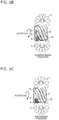
- Fig. 2C is a diagram illustrating a discharge process included in the compression principles of the screw compressor 100 according to Embodiment 1 of the present invention.
- Fig. 2A shows a state of the compression chamber 6 in the suction process.
- the screw rotor 2 is driven by the motor 3 to be rotated in the direction of the solid-line arrow. This reduces the volume of the compression chamber 6 as shown in Fig. 2B , and thereby the compression process is performed.
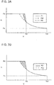
- Fig. 3A is a PV diagram illustrating a case of insufficient compression included in improper compression according to Embodiment 1 of the present invention.
- Fig. 3B is a PV diagram illustrating a case of insufficient compression included in conventional improper compression.
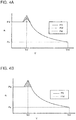
- Fig. 4A is a PV diagram illustrating a case of over compression included in the improper compression according to Embodiment 1 of the present invention.
- Fig. 4B is a PV diagram illustrating a case of over compression included in the conventional improper compression.
- Fig. 5A is a diagram illustrating a minimum area S of the refrigerant flow in the discharge outlet 9 at a start of opening thereof in the screw compressor 100 according to Embodiment 1 of the present invention.
- Fig. 5A is a diagram illustrating a minimum area S of the refrigerant flow in the discharge outlet 9 at a start of opening thereof in the screw compressor 100 according to Embodiment 1 of the present invention.
- Fig. 5A is a diagram illustrating a minimum area S of the
- FIG. 5B is a diagram illustrating the minimum area S of the refrigerant flow in the discharge outlet 9 partway through opening thereof in the screw compressor 100 according to Embodiment 1 of the present invention.
- Fig. 5C is a diagram illustrating the minimum area S of the refrigerant flow in the discharge outlet 9 close to maximum opening thereof in the screw compressor 100 according to Embodiment 1 of the present invention.
- Fig. 6 is a diagram illustrating a relationship between a screw rotation angle of the screw compressor 100 and the minimum area S of the refrigerant flow according to Embodiment 1 of the present invention.
- Fig. 7A is a diagram illustrating a minimum area S of the refrigerant flow in a discharge outlet at a start of opening thereof in a conventional screw compressor.
- FIG. 7B is a diagram illustrating the minimum area S of the refrigerant flow in the discharge outlet partway through opening thereof in the conventional screw compressor.
- Fig. 7C is a diagram illustrating the minimum area S of the refrigerant flow in the discharge outlet close to maximum opening thereof in the conventional screw compressor.
- Fig. 8 is a diagram illustrating a relationship between a screw rotation angle of the conventional screw compressor and the minimum area S of the refrigerant flow.
- the compression chamber is communicated to the discharge outlet before the refrigerant gas pressure in the compression chamber reaches a high pressure Pd.
- the minimum area S of the refrigerant flow in the discharge outlet in which the refrigerant actually flows, is automatically determined to be broadened in accordance with the time course with rotation of the screw rotor.
- the minimum area S of the refrigerant flow is broadened from the start of opening corresponding to the screw rotation angle. Therefore, as shown in Fig. 7A , the discharge outlet is opened in the discharge port before reaching the discharge pressure. Further, as shown in Fig.
- the minimum area S of the refrigerant flow in the discharge outlet after opening is large. Consequently, the refrigerant gas in the discharge flow path flows from the discharge outlet back into the compression chamber, to thereby result in a pattern of conventional compression P2 in which the pressure is sharply increased as compared to a pattern of ideal compression Pid. Consequently, increase in power by the area of the shaded portion results in a loss as insufficient compression loss.
- the minimum area S of the refrigerant flow in the discharge outlet 9, in which the refrigerant actually flows can be adjusted to be narrowed, not to be broadened, at the start of opening between the land part 2a of the screw rotor 2 and the edge part of the discharge port valve 10 formed into the stepped shape 13 corresponding to the time course with rotation of the screw rotor 2.
- the adjustment portion in which the minimum area S of the refrigerant flow is adjusted not to be broadened at the start of opening is the portion A in the bumped shape of a single stage shown in Fig. 6 .
- Embodiment 1 in the operation conditions of a low operation load factor with a low compression ratio and a low frequency, the compression results in a pattern of performed compression P3 shown in Fig. 4A due to a small refrigerant circulation amount, thereby the power loss by the area of the shaded portion is improved, and it is possible to keep the effect of discharge pressure loss to be small, and to keep the effect of increase in power to be small.
- the edge part of the discharge port valve 10, in which the discharge outlet 9 is opened is formed into the stepped shape 13 of N steps.
- the stepped shape 13 makes it difficult to broaden the minimum area S of the refrigerant flow in the discharge outlet 9, in which the refrigerant actually flows, immediately after the screw grooves 5 are communicated to the discharge outlet 9. Then, thereafter, the minimum area S of the refrigerant flow is broadened with the movement of the screw grooves 5 toward the discharge side.
- Embodiment 1 it is possible to form the minimum area S of the refrigerant flow in the discharge outlet 9, in which the refrigerant actually flows, corresponding to wide operating pressure ratio without sliding the discharge port valve 10, and thereby the high-performance screw compressor 100 in the wide operation range can be obtained.
- variable inner volume ratio mechanism and control for causing the discharge port valve 10 to serve as the variable inner volume ratio valve are unnecessary, a compact and inexpensive screw compressor 100 can be obtained.
- Embodiment 1 the number of steps in the stepped shape 13 was assumed to be N steps including a single step and multiple steps.
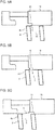
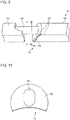
- Fig. 9 is a schematic view illustrating a discharge port valve 10 according to Embodiment 2 of the present invention.
- Fig. 10 is an illustration diagram illustrating a cross section A-A of the discharge port valve 10 shown in Fig. 9 according to Embodiment 2 of the present invention.
- a member 10a provided with a function of suppressing rotation of the discharge port valve 10 and a member 10b forming part of the discharge outlet 9 are integrated by providing a rod-shaped coupling part 10c therebetween.
- the discharge port valve 10 is formed on the outer side in the radial direction of the hollow part 1a of the casing body 1 and contained in the semi-cylindrical container groove 11 extending in the direction of the rotation shaft of the screw rotor 2, and fixed thereto.
- the edge part of the discharge port valve 10, in which the discharge outlet 9 facing an outer circumference of the screw rotor 2 is opened, is formed into a stepped shape 13 with a single step shifting the position thereof toward the outer side in the radial direction on the downstream side of the discharge flow path 8.
- the stepped shape 13 with a single step refers to a shape having a step end surface 10e of a single step and two surfaces 10f arranged in line along the outer circumference of the screw rotor 2.
- IPLV 0.01 x A + 0.42 x B + 0.45 x C + 0.12 x D, where
- the coefficient of performance differs in response to the load in operation; moreover, the time with the load of 75% occupies 42% of the annual operation time and the time with the load of 50% occupies 45% of the annual operation time, and therefore, the weight is larger in these two conditions.
- IPLV 0.01 x A + 0.47 x B + 0.37 x C + 0.15 x D
- the weight is different in each operation load factor.
- the time with the load of 75% occupies 47% of the annual operation time and the time with the load of 50% occupies 37% of the annual operation time, and therefore, the weight is larger in these two conditions.
- one step end surface 10e of the stepped shape 13 and one end surface 10d closer to the coupling part 10c in the discharge port valve 10 are formed with end surface inclination optimized in the two conditions having a large weight of the integrated part load value IPLV.
- two end surface inclinations are formed by optimization in the two conditions B and C having a large weight of the integrated part load value IPLV.
- the end surface inclination is formed into a curved surface shape corresponding to a discharge side end of the land in the screw rotor, which the discharge port valve, not in the conventional stepped shape, in the two conditions B and C in the sliding position faces.
- the screw compressor 100 having high integrated part load value IPLV. Moreover, since the discharge port valve 10 does not require a mechanism for serving as the variable inner volume ratio valve and control, the screw compressor 100, which is more compact and less expensive than a conventional one, can be obtained.
- Fig. 11 is a schematic view illustrating the discharge port valve 10 according to Embodiment 3 of the present invention.
- Fig. 12 is an illustration diagram illustrating a cross section B-B of the discharge port valve 10 shown in Fig. 11 according to Embodiment 3 of the present invention.
- a member 10a provided with a function of suppressing rotation of the discharge port valve 10 and a member 10b forming part of the discharge outlet 9 are integrated by providing a rod-shaped coupling part 10c therebetween.
- the discharge port valve 10 is formed on the outer side in the radial direction of the hollow part 1a of the casing body 1 and contained in the semi-cylindrical container groove 11 extending in the direction of the rotation shaft of the screw rotor 2, and fixed thereto.
- the edge part of the discharge port valve 10, in which the discharge outlet 9 facing an outer circumference of the screw rotor 2 is opened, is formed into a stepped shape 13 with two steps shifting the position thereof toward the outer side in the radial direction on the downstream side of the discharge flow path 8.
- the stepped shape 13 with two steps refers to a shape having a step end surface 10e of two steps and three surfaces 10f arranged in line along the outer circumference of the screw rotor 2.
- three end surface inclinations are formed by optimization in the three conditions B, C and D having a large weight of the integrated part load value IPLV.
- the end surface inclination is formed into a curved surface shape corresponding to a discharge side end of the land in the screw rotor, which the discharge port valve, not in the conventional stepped shape, in the three conditions B, C and D in the sliding position faces.
- the screw compressor 100 having higher integrated part load value IPLV than Embodiment 2. Moreover, since the discharge port valve 10 does not require a mechanism for serving as the variable inner volume ratio valve and control, the screw compressor 100, which is more compact and less expensive than a conventional one, can be obtained.
- Fig. 13 is a schematic view illustrating the discharge port valve 10 according to Embodiment 4 of the present invention.
- Fig. 14 is an illustration diagram illustrating a cross section C-C of the discharge port valve 10 shown in Fig. 13 according to Embodiment 4 of the present invention.
- a member 10a provided with a function of suppressing rotation of the discharge port valve 10 and a member 10b forming part of the discharge outlet 9 are integrated by providing a rod-shaped coupling part 10c therebetween.
- the discharge port valve 10 is formed on the outer side in the radial direction of the hollow part 1a of the casing body 1 and contained in the semi-cylindrical container groove 11 extending in the direction of the rotation shaft of the screw rotor 2, and fixed thereto.
- the edge part of the discharge port valve 10, in which the discharge outlet 9 facing an outer circumference of the screw rotor 2 is opened, is formed into a stepped shape 13 with three steps shifting the position thereof toward the outer side in the radial direction on the downstream side of the discharge flow path 8.
- the stepped shape 13 with three steps refers to a shape having a step end surface 10e of three steps and four surfaces 10f arranged in line along the outer circumference of the screw rotor 2.
- Embodiment 4 three step end surfaces 10e of the stepped shape 13 and one end surface 10d closer to the coupling part 10c in the discharge port valve 10 are formed with end surface inclination optimized in four conditions A, B, C and D of the integrated part load value IPLV.
- the end surface inclination is formed into a curved surface shape corresponding to a discharge side end of the land in the screw rotor, which the discharge port valve, not in the conventional stepped shape, in the four conditions A, B, C and D in the sliding position faces.
- the screw compressor 100 having higher integrated part load value IPLV than Embodiment 3. Moreover, since the discharge port valve 10 does not require a mechanism for serving as the variable inner volume ratio valve and control, the screw compressor 100, which is more compact and less expensive than a conventional one, can be obtained.
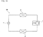
- Fig. 15 is a refrigerant circuit diagram illustrating a refrigeration cycle apparatus 200 to which the screw compressor 100 according to Embodiment 5 of the present invention is applied.
- the refrigeration cycle apparatus 200 includes the screw compressor 100, a condenser 80, an expansion valve 81 and an evaporator 82. These screw compressor 100, condenser 80, expansion valve 81 and evaporator 82 are connected via the refrigerant pipe to form the refrigeration cycle circuit. The refrigerant flowing out of the evaporator 82 is sucked into the screw compressor 100 to have high temperature and high pressure. The refrigerant that became high temperature and high pressure is condensed in the condenser 80 to become liquid.
- the refrigerant that became liquid is subjected to pressure reduction and expansion by the expansion valve 81 to enter a two-phase gas-liquid state of low temperature and low pressure, and thereby the two-phase gas-liquid refrigerant is subjected to heat exchange in the evaporator 82.
- the screw compressors 100 in the Embodiments 1 to 4 can be applied to such a refrigeration cycle apparatus 200.
- the refrigeration cycle apparatus 200 include an air-conditioning apparatus, a refrigeration device, a water heater and the like.
- the screw compressor 100 includes the casing body 1 having the hollow part 1a.
- the screw compressor 100 also includes the screw rotor 2 rotating around the rotation shaft in the hollow part 1a of the casing body 1.
- the screw compressor 100 also includes a semi-cylindrical container groove 11 formed on the outer side in the radial direction of the hollow part 1a of the casing body 1 and extending in the direction of the rotation shaft of the screw rotor 2.
- the screw compressor 100 also includes the discharge port valve 10 contained in the container groove 11.
- the edge part of the discharge port valve 10, in which the discharge outlet 9 facing an outer circumference of the screw rotor 2 is opened, is formed into a stepped shape 13 changing a flow path area of the discharge flow path 8 in a stepwise manner.
- the edge part of the discharge port valve 10, in which the discharge outlet 9 facing an outer circumference of the screw rotor 2 is opened, is formed into a stepped shape 13 changing a flow path area of the discharge flow path 8 in a stepwise manner. Therefore, the minimum area S of refrigerant flow in the discharge outlet 9, in which the refrigerant actually flows, can be adjusted between a land part 2a of the screw rotor 2 and the edge part of the discharge port valve 10 formed into the stepped shape 13 corresponding to the time course with the rotation of the screw rotor 2.
- a member 10a provided with a function of suppressing rotation of the discharge port valve 10 and a member 10b forming part of the discharge outlet 9 are integrated by providing a rod-shaped coupling part 10c therebetween.
- the stepped shape 13 is formed in the edge part, in which the discharge outlet 9 is opened, of the member 10b forming part of the discharge outlet 9.
- the discharge port valve 10 is fixed.
- variable inner volume ratio mechanism and control for causing the discharge port valve 10 to serve as the variable inner volume ratio valve are unnecessary, a compact and inexpensive screw compressor 100 can be obtained.
- the stepped shape 13 includes a single step and end surface inclination of the stepped shape 13 is formed by optimization in two conditions having a large weight of the integrated part load value IPLV.
- the stepped shape 13 includes two steps and end surface inclination of the stepped shape 13 is formed by optimization in three conditions having a large weight of the integrated part load value IPLV.
- the stepped shape 13 includes three steps and end surface inclination of the stepped shape 13 is formed by optimization in four conditions having a large weight of the integrated part load value IPLV.
- the refrigeration cycle apparatus 200 includes the screw compressor 100.
- the discharge port valve 10 was fixed inside the container groove 11.
- the discharge port valve 10 may be driven by control in which, for example, the drive patterns are simplified into only two patterns or others. Even in such a case, it is possible to improve the improper compression loss by simplifying the control.
- the above-described stepped shape 13 may be applied to a slide valve capable of adjusting the compression capacity.
Landscapes
- Engineering & Computer Science (AREA)
- Mechanical Engineering (AREA)
- General Engineering & Computer Science (AREA)
- Applications Or Details Of Rotary Compressors (AREA)
Abstract
Description
- The present invention relates to a screw compressor and a refrigeration cycle apparatus that do not require complex control.
- In a screw compressor, there is known a technique that includes a variable inner volume ratio valve, which is a slide valve adjusting a timing of starting discharge to make an inner volume ratio Vi adjustable, to thereby adjust an opening degree of the variable inner volume ratio valve by a driving force from a driving device in accordance with an operating pressure ratio (for example, refer to Patent Literature 1).
- A conventional variable inner volume ratio valve used for the screw compressor is controlled as shown in
Fig. 1 andFig. 2 ofPatent Literature 1. Specifically, upon calculating an optimum inner volume ratio value from a discharge pressure HP and a suction pressure LP and obtaining a current inner volume ratio value from a position detection unit, the variable inner volume ratio valve is controlled by a driving device coupled to the variable inner volume ratio valve so that a difference between the current inner volume ratio value and the optimum inner volume ratio value will be decreased. Further, to bring the current inner volume ratio value close to the optimum inner volume ratio value in actual operation, the opening degree of the variable inner volume ratio valve is adjusted to minimize a motor driving power. - Here, the inner volume ratio Vi in the screw compressor is, for example, as disclosed in
Patent Literature 2, a ratio between a tooth groove space volume in sucking and a tooth groove space volume just before discharging, and represents a ratio between a volume when suction is completed and a volume when a discharge port is opened. - Regarding a conventional discharge port valve, a discharge-side edge part of the discharge port valve facing an outer circumference of a screw rotor is formed into a corner-portion shape without steps in which an axial direction plane of a rotation shaft of the screw rotor and an orthogonal plane thereof are bent. Consequently, the minimum area of refrigerant flow in the discharge outlet, in which the refrigerant actually flows, becomes the size between the land part of the screw rotor and the discharge-side edge part of the discharge port valve. Therefore, when the timing to start opening the discharge outlet in the conventional discharge port valve of the fixed type is determined, the minimum area of refrigerant flow in the discharge outlet, in which the refrigerant actually flows, is automatically determined to be broadened in accordance with the time course with rotation of the screw rotor.
- If the inner volume ratio Vi is adapted to a low-load operation with a low compression ratio and a low flow rate that occupies the large part of operation time of an air-conditioning device per year, in a high-load operation with a high compression ratio and a high flow rate, a discharge outlet is opened at a discharge port before reaching the discharge pressure. Further, since the minimum area of refrigerant flow in the discharge outlet after opening is large, a large amount of refrigerant gas flows back into a compression chamber, and thereby improper compression loss is generated.
- On the other hand, if the inner volume ratio Vi is adapted to the high-load operation, in the low-load operation, the refrigerant gas is excessively compressed beyond the high-pressure side pressure until the discharge outlet is opened in the discharge port and the improper compression loss is increased by over compression, to thereby result in deterioration of efficiency throughout the year.
-
- Patent Literature 1: Japanese Patent No.
4147891 - Patent Literature 2: Japanese Unexamined Patent Application Publication No.
62-87687 - Therefore, the screw compressor using the variable inner volume ratio valve has conventionally been suggested. However, a complex controller was required to control the variable inner volume ratio valve and there has been a problem of increased costs.
- The present invention has been made to solve the above problem, and has an object to obtain a highly efficient screw compressor and a refrigeration cycle apparatus simplifying control of a discharge port valve.
- A screw compressor according to one embodiment of the present invention includes: a casing body having a hollow part; a screw rotor rotating around a rotation shaft in the hollow part of the casing body; a semi-cylindrical groove formed on an outer side in a radial direction of the hollow part of the casing body and extending in a direction of the rotation shaft of the screw rotor; and a discharge port valve contained in the semi-cylindrical groove, wherein an edge part of the discharge port valve, in which a discharge outlet facing an outer circumference of the screw rotor is opened, is formed into a stepped shape changing a flow path area of a discharge flow path in a stepwise manner.
- A refrigeration cycle apparatus according to one embodiment of the present invention includes the above-described screw compressor.
- According to a screw compressor and a refrigeration cycle apparatus according to one embodiment of the present invention, an edge part of a discharge port valve, in which a discharge outlet facing an outer circumference of a screw rotor was opened, was formed into a stepped shape changing a flow path area of a discharge flow path in a stepwise manner. Therefore, the minimum area of refrigerant flow in the discharge outlet, in which the refrigerant actually flows, can be adjusted between a land part of the screw rotor and the edge part of the discharge port valve formed into the stepped shape corresponding to the time course with rotation of the screw rotor. In other words, in the edge part, which is formed into the stepped shape, of the discharge port valve, corresponding to the time course with rotation of the screw rotor, a position set to a minimum width facing the land part of the screw rotor is shifted in accordance with the stepped shape. Consequently, without requiring complex control for the discharge port valve, it is possible to reduce effects of improper compression loss in wide ranging operation conditions from a low compression ratio to a high compression ratio. Therefore, a simple and inexpensive configuration can be achieved, and the yearly operation efficiency can be increased.
-
-
Fig. 1 is a schematic configuration view of a screw compressor according toEmbodiment 1 of the present invention. -
Fig. 2A is a diagram illustrating a suction process included in the compression principles of the screw compressor according toEmbodiment 1 of the present invention. -
Fig. 2B is a diagram illustrating a compression process included in the compression principles of the screw compressor according toEmbodiment 1 of the present invention. -
Fig. 2C is a diagram illustrating a discharge process included in the compression principles of the screw compressor according toEmbodiment 1 of the present invention. -
Fig. 3A is a PV diagram illustrating a case of insufficient compression included in improper compression according toEmbodiment 1 of the present invention. -
Fig. 3B is a PV diagram illustrating a case of insufficient compression included in conventional improper compression. -
Fig. 4A is a PV diagram illustrating a case of over compression included in the improper compression according toEmbodiment 1 of the present invention. -
Fig. 4B is a PV diagram illustrating a case of over compression included in the conventional improper compression. -
Fig. 5A is a diagram illustrating a minimum area of the refrigerant flow in a discharge outlet at a start of opening thereof in the screw compressor according toEmbodiment 1 of the present invention. -
Fig. 5B is a diagram illustrating the minimum area of the refrigerant flow in the discharge outlet partway through opening thereof in the screw compressor according toEmbodiment 1 of the present invention. -
Fig. 5C is a diagram illustrating the minimum area of the refrigerant flow in the discharge outlet close to maximum opening thereof in the screw compressor according toEmbodiment 1 of the present invention. -
Fig. 6 is a diagram illustrating a relationship between a screw rotation angle of the screw compressor and the minimum area of the refrigerant flow according toEmbodiment 1 of the present invention. -
Fig. 7A is a diagram illustrating a minimum area of the refrigerant flow in a discharge outlet at a start of opening thereof in a conventional screw compressor. -
Fig. 7B is a diagram illustrating the minimum area of the refrigerant flow in the discharge outlet partway through opening thereof in the conventional screw compressor. -
Fig. 7C is a diagram illustrating the minimum area of the refrigerant flow in the discharge outlet close to maximum opening thereof in the conventional screw compressor. -
Fig. 8 is a diagram illustrating a relationship between a screw rotation angle of the conventional screw compressor and the minimum area of the refrigerant flow. -
Fig. 9 is a schematic view illustrating a discharge port valve according toEmbodiment 2 of the present invention. -
Fig. 10 is an illustration diagram illustrating a cross section A-A of the discharge port valve shown inFig. 9 according toEmbodiment 2 of the present invention. -
Fig. 11 is a schematic view illustrating a discharge port valve according toEmbodiment 3 of the present invention. -
Fig. 12 is an illustration diagram illustrating a cross section B-B of the discharge port valve shown inFig. 11 according toEmbodiment 3 of the present invention. -
Fig. 13 is a schematic view illustrating a discharge port valve according toEmbodiment 4 of the present invention. -
Fig. 14 is an illustration diagram illustrating a cross section C-C of the discharge port valve shown inFig. 13 according toEmbodiment 4 of the present invention. -
Fig. 15 is a refrigerant circuit diagram illustrating a refrigeration cycle apparatus to which a screw compressor according toEmbodiment 5 of the present invention is applied. - Hereinafter, the embodiments of the present invention will be described based on the attached drawings.
- Note that those components assigned with the same signs in respective figures are the same or corresponding components, and this is common throughout the text of the specification.
- Further, forms of constituent elements shown throughout the text in the specification are only examples, which do not limit the present invention to these descriptions.
-
Fig. 1 is a schematic configuration view of ascrew compressor 100 according toEmbodiment 1 of the present invention. By use ofFig. 1 , a schematic configuration of thescrew compressor 100 will be described. - The
screw compressor 100 according toEmbodiment 1 is a single-screw compressor. Thescrew compressor 100 is used in a refrigeration cycle apparatus expected to operate in a wide range of compression ratio of, for example, an air-conditioning apparatus, a refrigeration device, a water heater and the like. - As shown in
Fig. 1 , thescrew compressor 100 includes acylindrical casing body 1 having ahollow part 1a inside thereof; and ascrew rotor 2 contained in thehollow part 1a in thecasing body 1. - In the shaft direction of the rotation shaft of the
screw rotor 2, amotor 3 for rotationally driving thescrew rotor 2 is included. Themotor 3 is configured with astator 3a fixed to thecasing body 1 and amotor rotor 3b disposed inside thestator 3a with a gap. The rotation speed of themotor 3 is controlled by an inverter system, which is not shown. - The
screw rotor 2 and themotor rotor 3b are mutually disposed on a same shaft line of the rotation shaft, and both of them are fixed to ascrew shaft 4. Thescrew rotor 2 is coupled to themotor rotor 3b fixed to thescrew shaft 4, to be rotationally driven. - On an outer circumferential surface of the
screw rotor 2,multiple screw grooves 5 in a spiral shape are formed. - A
compression chamber 6 of thescrew compressor 100 is formed by themultiple screw grooves 5 in the spiral shape, an inner cylinder surface forming thehollow part 1a of thecasing body 1, thescrew rotor 2 and a pair ofgate rotors 7 having multiple teeth engaged with thescrew rotor 2. - In the
casing body 1, a discharge pressure side and a suction pressure side are divided by a dividing wall, which is not-shown. - On the discharge pressure side of the
casing body 1, adischarge outlet 9 opened in thedischarge flow path 8 is formed. - On the inner cylinder surface of the
casing body 1, there is formed asemi-cylindrical container groove 11 for adischarge port valve 10 projecting toward the outer side in the radial direction and extending in the direction of rotation shaft of thescrew rotor 2. Thecontainer groove 11 corresponds to a semi-cylindrical groove of the present invention. - In the
container groove 11, thedischarge port valve 10 forming part of thedischarge outlet 9 and thedischarge flow path 8 is provided. - The
discharge port valve 10 is fixed inside thecontainer groove 11. Thecontainer groove 11 is opened on the left side of the figure to be closed by alid material 12 on the left end part, in the figure, of thescrew compressor 100. The opening of thecontainer groove 11 is to insert thedischarge port valve 10 into thecontainer groove 11. - In the
discharge port valve 10, amember 10a provided with a function of suppressing rotation of thedischarge port valve 10 and amember 10b forming part of thedischarge outlet 9 are integrated by providing a rod-shapedcoupling part 10c therebetween. The shape of thedischarge port valve 10 is as shown inFigs. 9 to 14 in the embodiments to be described later. - An edge part of the
discharge port valve 10, in which thedischarge outlet 9 facing an outer circumference of thescrew rotor 2 is opened, is formed into a steppedshape 13 changing a flow path area of thedischarge flow path 8 in a stepwise manner. In other words, the steppedshape 13 is formed in the edge part, in which thedischarge outlet 9 is opened, of themember 10b forming part of thedischarge outlet 9 on the suction pressure side in the direction of rotation shaft. - The stepped
shape 13 includes a single step or multiple steps; here, the steppedshape 13 is assumed to include N steps. The steppedshape 13 is formed only in the edge part, in which thedischarge outlet 9 is opened, of themember 10b forming part of thedischarge outlet 9. At an end part of themember 10b forming part of thedischarge outlet 9 in thedischarge port valve 10, the steppedshape 13 narrows the flow path width of thedischarge flow path 8 in the rotation shaft direction in a stepwise manner from thedischarge outlet 9 toward the outer side in the radial direction on the downstream side of thedischarge flow path 8. Moreover, at an end part of themember 10b forming part of thedischarge outlet 9 in thedischarge port valve 10, the steppedshape 13 narrows the flow path area of thedischarge flow path 8 in a stepwise manner from themember 10a provided with a function of suppressing rotation of thedischarge port valve 10 toward the rotation shaft side on the upstream side of thedischarge flow path 8. - The
discharge port valve 10 forms the outside of the radial direction on the downstream side of thedischarge flow path 8 in the steppedshape 13 narrowing the flow path area of thedischarge flow path 8 in the stepwise manner on oneend surface 10d on the side of the coupling part, and reduces the thickness of themember 10a provided with the function of suppressing rotation of thedischarge port valve 10, to thereby broaden the flow path area of thedischarge flow path 8. In other words, thedischarge port valve 10 once narrows down the flow path area of thedischarge flow path 8 from thedischarge outlet 9, and thereafter enlarges thereof. - Next, operations of the
screw compressor 100 according toEmbodiment 1 will be described. -
Fig. 2A is a diagram illustrating a suction process included in the compression principles of thescrew compressor 100 according toEmbodiment 1 of the present invention.Fig. 2B is a diagram illustrating a compression process included in the compression principles of thescrew compressor 100 according toEmbodiment 1 of the present invention.Fig. 2C is a diagram illustrating a discharge process included in the compression principles of thescrew compressor 100 according toEmbodiment 1 of the present invention. - As shown in
Figs. 2A to 2C , thescrew rotor 2 is rotated by themotor 3 via thescrew shaft 4, and thereby the teeth of thegate rotor 7 relatively move in thescrew grooves 5 forming thecompression chamber 6. Consequently, assuming that the suction process, the compression process and the discharge process constitute one cycle, the one cycle is repeated in thecompression chamber 6. Here, focusing on thecompression chamber 6 enclosed by the bold lines inFigs. 2A to 2C , each of the processes will be described. -
Fig. 2A shows a state of thecompression chamber 6 in the suction process. Thescrew rotor 2 is driven by themotor 3 to be rotated in the direction of the solid-line arrow. This reduces the volume of thecompression chamber 6 as shown inFig. 2B , and thereby the compression process is performed. - When the
screw rotor 2 is subsequently rotated, as shown inFig. 2C , thecompression chamber 6 is communicated to thedischarge outlet 9 formed by the inner cylinder surface of thecasing body 1 and thedischarge port valve 10, and thereby the discharge process is performed. Consequently, the high-pressure refrigerant gas compressed in thecompression chamber 6 passes through thedischarge flow path 8 from thedischarge outlet 9, and is discharged to the outside of thescrew compressor 100. Then, on the back of thescrew rotor 2, similar compression is performed again. - Next, effects of the
screw compressor 100 according toEmbodiment 1 will be described. -
Fig. 3A is a PV diagram illustrating a case of insufficient compression included in improper compression according toEmbodiment 1 of the present invention.Fig. 3B is a PV diagram illustrating a case of insufficient compression included in conventional improper compression.Fig. 4A is a PV diagram illustrating a case of over compression included in the improper compression according toEmbodiment 1 of the present invention.Fig. 4B is a PV diagram illustrating a case of over compression included in the conventional improper compression.Fig. 5A is a diagram illustrating a minimum area S of the refrigerant flow in thedischarge outlet 9 at a start of opening thereof in thescrew compressor 100 according toEmbodiment 1 of the present invention.Fig. 5B is a diagram illustrating the minimum area S of the refrigerant flow in thedischarge outlet 9 partway through opening thereof in thescrew compressor 100 according toEmbodiment 1 of the present invention.Fig. 5C is a diagram illustrating the minimum area S of the refrigerant flow in thedischarge outlet 9 close to maximum opening thereof in thescrew compressor 100 according toEmbodiment 1 of the present invention.Fig. 6 is a diagram illustrating a relationship between a screw rotation angle of thescrew compressor 100 and the minimum area S of the refrigerant flow according toEmbodiment 1 of the present invention.Fig. 7A is a diagram illustrating a minimum area S of the refrigerant flow in a discharge outlet at a start of opening thereof in a conventional screw compressor.Fig. 7B is a diagram illustrating the minimum area S of the refrigerant flow in the discharge outlet partway through opening thereof in the conventional screw compressor.Fig. 7C is a diagram illustrating the minimum area S of the refrigerant flow in the discharge outlet close to maximum opening thereof in the conventional screw compressor.Fig. 8 is a diagram illustrating a relationship between a screw rotation angle of the conventional screw compressor and the minimum area S of the refrigerant flow. - In the case of insufficient compression shown in
Fig. 3B , the compression chamber is communicated to the discharge outlet before the refrigerant gas pressure in the compression chamber reaches a high pressure Pd. In other words, in the conventional screw compressor, as shown inFigs. 7A to 7C , the minimum area S of the refrigerant flow in the discharge outlet, in which the refrigerant actually flows, is automatically determined to be broadened in accordance with the time course with rotation of the screw rotor. As shown inFig. 8 , the minimum area S of the refrigerant flow is broadened from the start of opening corresponding to the screw rotation angle. Therefore, as shown inFig. 7A , the discharge outlet is opened in the discharge port before reaching the discharge pressure. Further, as shown inFig. 7B , the minimum area S of the refrigerant flow in the discharge outlet after opening is large. Consequently, the refrigerant gas in the discharge flow path flows from the discharge outlet back into the compression chamber, to thereby result in a pattern of conventional compression P2 in which the pressure is sharply increased as compared to a pattern of ideal compression Pid. Consequently, increase in power by the area of the shaded portion results in a loss as insufficient compression loss. - On the other hand, as shown in
Figs. 5A to 5C , inEmbodiment 1, in the operation conditions of a high operation load factor with a high compression ratio and a high frequency, the minimum area S of the refrigerant flow in thedischarge outlet 9, in which the refrigerant actually flows, can be adjusted to be narrowed, not to be broadened, at the start of opening between theland part 2a of thescrew rotor 2 and the edge part of thedischarge port valve 10 formed into the steppedshape 13 corresponding to the time course with rotation of thescrew rotor 2. The adjustment portion in which the minimum area S of the refrigerant flow is adjusted not to be broadened at the start of opening is the portion A in the bumped shape of a single stage shown inFig. 6 . As described above, in the edge part of thedischarge port valve 10, which is formed into the steppedshape 13, corresponding to the time course with rotation of thescrew rotor 2, a position set to a minimum width facing theland part 2a of thescrew rotor 2 is shifted in accordance with the steppedshape 13. Therefore, as shown inFig. 5B , at the timing of occurrence of backflow of the refrigerant gas into thecompression chamber 6 due to insufficient compression immediately after communicating to thedischarge outlet 9, the minimum area S of the refrigerant flow is maintained to be small. Accordingly, the compression results in a pattern of performed compression P1 shown inFig. 3A , thereby the power loss by the area of the shaded portion is improved, and it is possible to keep the effect of increase in power due to backflow of the refrigerant gas to be small. - In the case of over compression shown in
Fig. 4B , since the compression is continued until the refrigerant gas pressure in thecompression chamber 6 reaches the volume Vd after reaching the high pressure Pd, the compression results in the pattern of the conventional compression P4. Consequently, increase in power by the area of the shaded portion results in a loss as over compression loss. - On the other hand, in
Embodiment 1, in the operation conditions of a low operation load factor with a low compression ratio and a low frequency, the compression results in a pattern of performed compression P3 shown inFig. 4A due to a small refrigerant circulation amount, thereby the power loss by the area of the shaded portion is improved, and it is possible to keep the effect of discharge pressure loss to be small, and to keep the effect of increase in power to be small. - As described above, in
Embodiment 1, the edge part of thedischarge port valve 10, in which thedischarge outlet 9 is opened, is formed into the steppedshape 13 of N steps. - With the configuration, the stepped
shape 13 makes it difficult to broaden the minimum area S of the refrigerant flow in thedischarge outlet 9, in which the refrigerant actually flows, immediately after thescrew grooves 5 are communicated to thedischarge outlet 9. Then, thereafter, the minimum area S of the refrigerant flow is broadened with the movement of thescrew grooves 5 toward the discharge side. - Consequently, in the operation conditions of the low operation load factor with the low compression ratio and the low frequency, due to a small refrigerant circulation amount, it is possible to keep the effect of discharge pressure loss to be small, and to keep the effect of increase in power to be small.
- On the other hand, in the operation conditions of the high operation load factor with the high compression ratio and the high frequency, there is the timing when, immediately after communicating to the
discharge outlet 9, backflow of the refrigerant gas into thecompression chamber 6 due to insufficient compression is likely to occur. At this time, the position set to the minimum width facing theland part 2a of thescrew rotor 2 is shifted in accordance with the steppedshape 13, and thereby the minimum area S of the refrigerant flow in thedischarge outlet 9, in which the refrigerant actually flows, is narrowed down. Accordingly, it is possible to keep the effect of increase in power due to backflow of the refrigerant gas to be small. - In other words, according to
Embodiment 1, it is possible to form the minimum area S of the refrigerant flow in thedischarge outlet 9, in which the refrigerant actually flows, corresponding to wide operating pressure ratio without sliding thedischarge port valve 10, and thereby the high-performance screw compressor 100 in the wide operation range can be obtained. - Moreover, since a variable inner volume ratio mechanism and control for causing the
discharge port valve 10 to serve as the variable inner volume ratio valve are unnecessary, a compact andinexpensive screw compressor 100 can be obtained. - In
Embodiment 1, the number of steps in the steppedshape 13 was assumed to be N steps including a single step and multiple steps. InEmbodiment 2, description will be given of a configuration when the number of steps is assumed to be one, namely, N = 1. Note that, inEmbodiment 2, it is assumed that different points fromEmbodiment 1 will be described, and components not described inEmbodiment 2 are the same as those ofEmbodiment 1. -
Fig. 9 is a schematic view illustrating adischarge port valve 10 according toEmbodiment 2 of the present invention.Fig. 10 is an illustration diagram illustrating a cross section A-A of thedischarge port valve 10 shown inFig. 9 according toEmbodiment 2 of the present invention. - In the
discharge port valve 10, amember 10a provided with a function of suppressing rotation of thedischarge port valve 10 and amember 10b forming part of thedischarge outlet 9 are integrated by providing a rod-shapedcoupling part 10c therebetween. - The
discharge port valve 10 is formed on the outer side in the radial direction of thehollow part 1a of thecasing body 1 and contained in thesemi-cylindrical container groove 11 extending in the direction of the rotation shaft of thescrew rotor 2, and fixed thereto. - The edge part of the
discharge port valve 10, in which thedischarge outlet 9 facing an outer circumference of thescrew rotor 2 is opened, is formed into a steppedshape 13 with a single step shifting the position thereof toward the outer side in the radial direction on the downstream side of thedischarge flow path 8. - The stepped
shape 13 with a single step refers to a shape having astep end surface 10e of a single step and twosurfaces 10f arranged in line along the outer circumference of thescrew rotor 2. - Here, regarding the refrigeration cycle apparatus, other than a coefficient of performance COP indicating energy consumption efficiency, there is an integrated part load value IPLV that is a coefficient of performance of a refrigeration cycle apparatus during a period. In the Air-Conditioning and Refrigeration Institute (ARI), the integrated part load value IPLV is calculated by the following calculation formula:

- A = COP with a load of 100%, B = COP with a load of 75%,
- C = COP with a load of 50%, and D = COP with a load of 25%.
- According to the calculation formula, the coefficient of performance differs in response to the load in operation; moreover, the time with the load of 75% occupies 42% of the annual operation time and the time with the load of 50% occupies 45% of the annual operation time, and therefore, the weight is larger in these two conditions.
- Moreover, in the Japan Refrigeration and Air Conditioning Industry Association (JRAIA), a similar index is defined as in the following formula.

- A = COP with a load of 100%, B = COP with a load of 75%,
- C = COP with a load of 50%, and D = COP with a load of 25%.
- In this manner, similar to the Air-Conditioning and Refrigeration Institute (ARI), the weight is different in each operation load factor. In other words, the time with the load of 75% occupies 47% of the annual operation time and the time with the load of 50% occupies 37% of the annual operation time, and therefore, the weight is larger in these two conditions.
- In
Embodiment 2, onestep end surface 10e of the steppedshape 13 and oneend surface 10d closer to thecoupling part 10c in thedischarge port valve 10 are formed with end surface inclination optimized in the two conditions having a large weight of the integrated part load value IPLV. - In other words, two end surface inclinations are formed by optimization in the two conditions B and C having a large weight of the integrated part load value IPLV.
- The end surface inclination is formed into a curved surface shape corresponding to a discharge side end of the land in the screw rotor, which the discharge port valve, not in the conventional stepped shape, in the two conditions B and C in the sliding position faces.
- With the configuration, it is possible to obtain the
screw compressor 100 having high integrated part load value IPLV. Moreover, since thedischarge port valve 10 does not require a mechanism for serving as the variable inner volume ratio valve and control, thescrew compressor 100, which is more compact and less expensive than a conventional one, can be obtained. - In
Embodiment 2, it was assumed that the number of steps in the steppedshape 13 was one, namely, N = 1. InEmbodiment 3, description will be given of a configuration when the number of steps is assumed to be two, namely, N = 2. Note that, inEmbodiment 3, it is assumed that different points fromEmbodiments Embodiment 3 are the same as those ofEmbodiment 1. -
Fig. 11 is a schematic view illustrating thedischarge port valve 10 according toEmbodiment 3 of the present invention.Fig. 12 is an illustration diagram illustrating a cross section B-B of thedischarge port valve 10 shown inFig. 11 according toEmbodiment 3 of the present invention. - In the
discharge port valve 10, amember 10a provided with a function of suppressing rotation of thedischarge port valve 10 and amember 10b forming part of thedischarge outlet 9 are integrated by providing a rod-shapedcoupling part 10c therebetween. - The
discharge port valve 10 is formed on the outer side in the radial direction of thehollow part 1a of thecasing body 1 and contained in thesemi-cylindrical container groove 11 extending in the direction of the rotation shaft of thescrew rotor 2, and fixed thereto. - The edge part of the
discharge port valve 10, in which thedischarge outlet 9 facing an outer circumference of thescrew rotor 2 is opened, is formed into a steppedshape 13 with two steps shifting the position thereof toward the outer side in the radial direction on the downstream side of thedischarge flow path 8. - The stepped
shape 13 with two steps refers to a shape having astep end surface 10e of two steps and threesurfaces 10f arranged in line along the outer circumference of thescrew rotor 2. - In
Embodiment 3, two step end surfaces 10e of the steppedshape 13 and oneend surface 10d closer to thecoupling part 10c in thedischarge port valve 10 are formed with end surface inclination optimized in three conditions having a large weight of the integrated part load value IPLV shown inEmbodiment 2. - In other words, three end surface inclinations are formed by optimization in the three conditions B, C and D having a large weight of the integrated part load value IPLV.
- The end surface inclination is formed into a curved surface shape corresponding to a discharge side end of the land in the screw rotor, which the discharge port valve, not in the conventional stepped shape, in the three conditions B, C and D in the sliding position faces.
- With the configuration, it is possible to obtain the
screw compressor 100 having higher integrated part load value IPLV thanEmbodiment 2. Moreover, since thedischarge port valve 10 does not require a mechanism for serving as the variable inner volume ratio valve and control, thescrew compressor 100, which is more compact and less expensive than a conventional one, can be obtained. - In
Embodiment 3, it was assumed that the number of steps in the steppedshape 13 was two, namely, N = 2. InEmbodiment 4, description will be given of a configuration when the number of steps is assumed to be three, namely, N = 3. Note that, inEmbodiment 4, it is assumed that different points fromEmbodiments 1 to 3 will be described, and components not described inEmbodiment 4 are the same as those ofEmbodiment 1. -
Fig. 13 is a schematic view illustrating thedischarge port valve 10 according toEmbodiment 4 of the present invention.Fig. 14 is an illustration diagram illustrating a cross section C-C of thedischarge port valve 10 shown inFig. 13 according toEmbodiment 4 of the present invention. - In the
discharge port valve 10, amember 10a provided with a function of suppressing rotation of thedischarge port valve 10 and amember 10b forming part of thedischarge outlet 9 are integrated by providing a rod-shapedcoupling part 10c therebetween. - The
discharge port valve 10 is formed on the outer side in the radial direction of thehollow part 1a of thecasing body 1 and contained in thesemi-cylindrical container groove 11 extending in the direction of the rotation shaft of thescrew rotor 2, and fixed thereto. - The edge part of the
discharge port valve 10, in which thedischarge outlet 9 facing an outer circumference of thescrew rotor 2 is opened, is formed into a steppedshape 13 with three steps shifting the position thereof toward the outer side in the radial direction on the downstream side of thedischarge flow path 8. - The stepped
shape 13 with three steps refers to a shape having astep end surface 10e of three steps and foursurfaces 10f arranged in line along the outer circumference of thescrew rotor 2. - In
Embodiment 4, three step end surfaces 10e of the steppedshape 13 and oneend surface 10d closer to thecoupling part 10c in thedischarge port valve 10 are formed with end surface inclination optimized in four conditions A, B, C and D of the integrated part load value IPLV. - The end surface inclination is formed into a curved surface shape corresponding to a discharge side end of the land in the screw rotor, which the discharge port valve, not in the conventional stepped shape, in the four conditions A, B, C and D in the sliding position faces.
- With the configuration, it is possible to obtain the
screw compressor 100 having higher integrated part load value IPLV thanEmbodiment 3. Moreover, since thedischarge port valve 10 does not require a mechanism for serving as the variable inner volume ratio valve and control, thescrew compressor 100, which is more compact and less expensive than a conventional one, can be obtained. -
Fig. 15 is a refrigerant circuit diagram illustrating arefrigeration cycle apparatus 200 to which thescrew compressor 100 according toEmbodiment 5 of the present invention is applied. - As shown in
Fig. 15 , therefrigeration cycle apparatus 200 includes thescrew compressor 100, acondenser 80, anexpansion valve 81 and anevaporator 82. Thesescrew compressor 100,condenser 80,expansion valve 81 andevaporator 82 are connected via the refrigerant pipe to form the refrigeration cycle circuit. The refrigerant flowing out of theevaporator 82 is sucked into thescrew compressor 100 to have high temperature and high pressure. The refrigerant that became high temperature and high pressure is condensed in thecondenser 80 to become liquid. The refrigerant that became liquid is subjected to pressure reduction and expansion by theexpansion valve 81 to enter a two-phase gas-liquid state of low temperature and low pressure, and thereby the two-phase gas-liquid refrigerant is subjected to heat exchange in theevaporator 82. - The screw compressors 100 in the
Embodiments 1 to 4 can be applied to such arefrigeration cycle apparatus 200. Note that examples of therefrigeration cycle apparatus 200 include an air-conditioning apparatus, a refrigeration device, a water heater and the like. - According to the above-described
Embodiments 1 to 5, thescrew compressor 100 includes thecasing body 1 having thehollow part 1a. Thescrew compressor 100 also includes thescrew rotor 2 rotating around the rotation shaft in thehollow part 1a of thecasing body 1. Thescrew compressor 100 also includes asemi-cylindrical container groove 11 formed on the outer side in the radial direction of thehollow part 1a of thecasing body 1 and extending in the direction of the rotation shaft of thescrew rotor 2. Thescrew compressor 100 also includes thedischarge port valve 10 contained in thecontainer groove 11. The edge part of thedischarge port valve 10, in which thedischarge outlet 9 facing an outer circumference of thescrew rotor 2 is opened, is formed into a steppedshape 13 changing a flow path area of thedischarge flow path 8 in a stepwise manner. - With the configuration, the edge part of the
discharge port valve 10, in which thedischarge outlet 9 facing an outer circumference of thescrew rotor 2 is opened, is formed into a steppedshape 13 changing a flow path area of thedischarge flow path 8 in a stepwise manner. Therefore, the minimum area S of refrigerant flow in thedischarge outlet 9, in which the refrigerant actually flows, can be adjusted between aland part 2a of thescrew rotor 2 and the edge part of thedischarge port valve 10 formed into the steppedshape 13 corresponding to the time course with the rotation of thescrew rotor 2. In other words, in the edge part of thedischarge port valve 10, which is formed into the steppedshape 13, corresponding to the time course with the rotation of thescrew rotor 2, a position set to a minimum width facing theland part 2a of thescrew rotor 2 is shifted in accordance with the steppedshape 13. Consequently, without requiring complex control for thedischarge port valve 10, it is possible to reduce effects of improper compression loss in wide ranging operation conditions from a low compression ratio to a high compression ratio. Therefore, a simple and inexpensive configuration can be achieved, and the yearly operation efficiency can be increased. - In the
discharge port valve 10, amember 10a provided with a function of suppressing rotation of thedischarge port valve 10 and amember 10b forming part of thedischarge outlet 9 are integrated by providing a rod-shapedcoupling part 10c therebetween. The steppedshape 13 is formed in the edge part, in which thedischarge outlet 9 is opened, of themember 10b forming part of thedischarge outlet 9. - With the configuration, it is possible to simplify the control of the
discharge port valve 10 to form the minimum area S of the refrigerant flow in thedischarge outlet 9, in which the refrigerant actually flows, corresponding to wide operating pressure ratio and thereby the high-performance screw compressor 100 in the wide operation range can be obtained. - Moreover, since the control for causing the
discharge port valve 10 to serve as the variable inner volume ratio valve is simplified, a compact andinexpensive screw compressor 100 can be obtained. - The
discharge port valve 10 is fixed. - With the configuration, it is possible to form the
discharge flow path 8 corresponding to wide operating pressure ratio without sliding thedischarge port valve 10, and thereby the high-performance screw compressor 100 in the wide operation range can be obtained. - Moreover, since a variable inner volume ratio mechanism and control for causing the
discharge port valve 10 to serve as the variable inner volume ratio valve are unnecessary, a compact andinexpensive screw compressor 100 can be obtained. - The stepped
shape 13 includes a single step and end surface inclination of the steppedshape 13 is formed by optimization in two conditions having a large weight of the integrated part load value IPLV. - With the configuration, it is possible to obtain the
screw compressor 100 having high integrated part load value IPLV. - The stepped
shape 13 includes two steps and end surface inclination of the steppedshape 13 is formed by optimization in three conditions having a large weight of the integrated part load value IPLV. - With the configuration, it is possible to obtain the
screw compressor 100 having high integrated part load value IPLV. - The stepped
shape 13 includes three steps and end surface inclination of the steppedshape 13 is formed by optimization in four conditions having a large weight of the integrated part load value IPLV. - With the configuration, it is possible to obtain the
screw compressor 100 having high integrated part load value IPLV. - The
refrigeration cycle apparatus 200 includes thescrew compressor 100. - With the configuration, a simple and inexpensive configuration can be achieved, and the yearly operation efficiency can be increased.
- Note that, in the above-described embodiments, the
discharge port valve 10 was fixed inside thecontainer groove 11. However, thedischarge port valve 10 may be driven by control in which, for example, the drive patterns are simplified into only two patterns or others. Even in such a case, it is possible to improve the improper compression loss by simplifying the control. Moreover, the above-described steppedshape 13 may be applied to a slide valve capable of adjusting the compression capacity. - Moreover, in the above-described embodiments, description was given by using the single-screw compressor as the screw compressor. However, other than this, a twin-screw compressor may be used as the screw compressor.
- 1
casing body 1ahollow part 2screw rotor 2a land part 3motor 3a stator3b motor rotor 4screw shaft 5screw groove 6compression chamber 7gate rotor 8discharge flow path 9discharge outlet 10discharge port valve 10a member provided with function of suppressing rotation ofdischarge port valve 10b member forming part ofdischarge outlet 10c coupling part 10d end surface closer tocoupling part 10estep end surface 10f surface along outer circumference ofscrew rotor 11container groove 12lid material 13 steppedshape 80condenser 81expansion valve 82evaporator 100screw compressor 200 refrigeration cycle apparatus
Claims (7)
- A screw compressor comprising:a casing body having a hollow part;a screw rotor rotating around a rotation shaft in the hollow part of the casing body;a semi-cylindrical groove formed on an outer side in a radial direction of the hollow part of the casing body and extending in a direction of the rotation shaft of the screw rotor; anda discharge port valve contained in the semi-cylindrical groove, whereinan edge part of the discharge port valve, in which a discharge outlet facing an outer circumference of the screw rotor is opened, is formed into a stepped shape changing a flow path area of a discharge flow path in a stepwise manner.
- The screw compressor of claim 1, wherein
the discharge port valve is provided with a rod-shaped coupling part between a member provided with a function of suppressing rotation of the discharge port valve and a member forming part of the discharge outlet to integrate the members, and
the stepped shape is formed in the edge part, in which the discharge outlet is opened, of the member forming part of the discharge outlet. - The screw compressor of claim 1 or 2, wherein the discharge port valve is fixed.
- The screw compressor of any one of claims 1 to 3, wherein the stepped shape includes a single step and end surface inclination of the stepped shape is formed by optimization in two conditions having a large weight of an integrated part load value IPLV.
- The screw compressor of any one of claims 1 to 3, wherein the stepped shape includes two steps and end surface inclination of the stepped shape is formed by optimization in three conditions having a large weight of an integrated part load value IPLV.
- The screw compressor of any one of claims 1 to 3, wherein the stepped shape includes three steps and end surface inclination of the stepped shape is formed by optimization in four conditions having a large weight of an integrated part load value IPLV.
- A refrigeration cycle apparatus comprising the screw compressor of any one of claims 1 to 6.
Applications Claiming Priority (1)
| Application Number | Priority Date | Filing Date | Title |
|---|---|---|---|
| PCT/JP2016/055145 WO2017145251A1 (en) | 2016-02-23 | 2016-02-23 | Screw compressor and refrigeration cycle device |
Publications (3)
| Publication Number | Publication Date |
|---|---|
| EP3421800A4 EP3421800A4 (en) | 2019-01-02 |
| EP3421800A1 true EP3421800A1 (en) | 2019-01-02 |
| EP3421800B1 EP3421800B1 (en) | 2020-03-25 |
Family
ID=59685991
Family Applications (1)
| Application Number | Title | Priority Date | Filing Date |
|---|---|---|---|
| EP16891410.9A Active EP3421800B1 (en) | 2016-02-23 | 2016-02-23 | Screw compressor and refrigeration cycle device |
Country Status (2)
| Country | Link |
|---|---|
| EP (1) | EP3421800B1 (en) |
| WO (1) | WO2017145251A1 (en) |
Families Citing this family (6)
| Publication number | Priority date | Publication date | Assignee | Title |
|---|---|---|---|---|
| WO2019220562A1 (en) * | 2018-05-16 | 2019-11-21 | 三菱電機株式会社 | Screw compressor |
| GB2581526A (en) * | 2019-02-22 | 2020-08-26 | J & E Hall Ltd | Single screw compressor |
| JP7112031B2 (en) * | 2019-03-01 | 2022-08-03 | 三菱電機株式会社 | screw compressor |
| EP3981987A4 (en) * | 2019-06-05 | 2022-06-29 | Mitsubishi Electric Corporation | Screw compressor, and refrigeration cycle device |
| CN112377408B (en) * | 2020-11-12 | 2022-06-17 | 河北恒工精密装备股份有限公司 | Screw rotor exhaust end face compensation method, compensation structure and screw compressor head |
| CN117108508B (en) * | 2023-09-06 | 2025-06-24 | 烟台市奥威制冷设备有限公司 | Screw compressor with four electromagnetic valves for automatically and steplessly efficiently adjusting internal volume ratio and control method |
Family Cites Families (5)
| Publication number | Priority date | Publication date | Assignee | Title |
|---|---|---|---|---|
| JPS59131593U (en) * | 1983-02-22 | 1984-09-04 | 株式会社神戸製鋼所 | Oil-free screw compressor with slide valve |
| JPH07111184B2 (en) * | 1988-12-05 | 1995-11-29 | 株式会社荏原製作所 | Screw compressor |
| WO2009078178A1 (en) * | 2007-12-17 | 2009-06-25 | Daikin Industries, Ltd. | Screw compressor |
| JP5865056B2 (en) * | 2011-12-16 | 2016-02-17 | 三菱電機株式会社 | Screw compressor |
| JP2014029133A (en) * | 2012-07-31 | 2014-02-13 | Mitsubishi Electric Corp | Screw compressor |
-
2016
- 2016-02-23 WO PCT/JP2016/055145 patent/WO2017145251A1/en not_active Ceased
- 2016-02-23 EP EP16891410.9A patent/EP3421800B1/en active Active
Also Published As
| Publication number | Publication date |
|---|---|
| EP3421800B1 (en) | 2020-03-25 |
| EP3421800A4 (en) | 2019-01-02 |
| WO2017145251A1 (en) | 2017-08-31 |
Similar Documents
| Publication | Publication Date | Title |
|---|---|---|
| EP3421800B1 (en) | Screw compressor and refrigeration cycle device | |
| US11852145B2 (en) | Rotary compressors with variable speed and volume control | |
| JP5734438B2 (en) | Volume ratio control system and method | |
| CN102777383B (en) | Compressor | |
| CN108953141B (en) | Positive displacement machine according to the screw principle, method for operating a positive displacement machine, vehicle air conditioning system and vehicle | |
| EP2634432B1 (en) | Screw compressor | |
| CN109715951B (en) | Variable volume ratio compressor | |
| EP3006740A1 (en) | Screw compressor and refrigeration cycle device | |
| CN110520624B (en) | Rotary compressor | |
| AU2005224499A1 (en) | Refrigeration system | |
| CN111315994B (en) | Variable Compressor Housing | |
| JPWO2017094057A1 (en) | Single screw compressor and refrigeration cycle equipment | |
| JP2002062020A (en) | refrigerator | |
| EP2412980B1 (en) | Single screw compressor | |
| JP2014142158A (en) | Refrigeration cycle device | |
| JP6193555B2 (en) | Refrigeration cycle equipment | |
| EP4088032B1 (en) | Volume ratio control system for a compressor | |
| EP4461958A1 (en) | Screw compressor and refrigeration device | |
| EP4461959A1 (en) | Screw compressor and refrigeration device | |
| WO2023243089A1 (en) | Air conditioning device | |
| JP2008032234A (en) | Compressor and heat pump apparatus using the same |
Legal Events
| Date | Code | Title | Description |
|---|---|---|---|
| STAA | Information on the status of an ep patent application or granted ep patent |
Free format text: STATUS: THE INTERNATIONAL PUBLICATION HAS BEEN MADE |
|
| PUAI | Public reference made under article 153(3) epc to a published international application that has entered the european phase |
Free format text: ORIGINAL CODE: 0009012 |
|
| STAA | Information on the status of an ep patent application or granted ep patent |
Free format text: STATUS: REQUEST FOR EXAMINATION WAS MADE |
|
| 17P | Request for examination filed |
Effective date: 20180620 |
|
| A4 | Supplementary search report drawn up and despatched |
Effective date: 20181106 |
|
| AK | Designated contracting states |
Kind code of ref document: A1 Designated state(s): AL AT BE BG CH CY CZ DE DK EE ES FI FR GB GR HR HU IE IS IT LI LT LU LV MC MK MT NL NO PL PT RO RS SE SI SK SM TR |
|
| AX | Request for extension of the european patent |
Extension state: BA ME |
|
| DAV | Request for validation of the european patent (deleted) | ||
| DAX | Request for extension of the european patent (deleted) | ||
| RIC1 | Information provided on ipc code assigned before grant |
Ipc: F04C 18/16 20060101AFI20190731BHEP Ipc: F04C 28/10 20060101ALI20190731BHEP Ipc: F04C 18/52 20060101ALI20190731BHEP |
|
| GRAP | Despatch of communication of intention to grant a patent |
Free format text: ORIGINAL CODE: EPIDOSNIGR1 |
|
| STAA | Information on the status of an ep patent application or granted ep patent |
Free format text: STATUS: GRANT OF PATENT IS INTENDED |
|
| INTG | Intention to grant announced |
Effective date: 20190911 |
|
| GRAS | Grant fee paid |
Free format text: ORIGINAL CODE: EPIDOSNIGR3 |
|
| GRAA | (expected) grant |
Free format text: ORIGINAL CODE: 0009210 |
|
| STAA | Information on the status of an ep patent application or granted ep patent |
Free format text: STATUS: THE PATENT HAS BEEN GRANTED |
|
| AK | Designated contracting states |
Kind code of ref document: B1 Designated state(s): AL AT BE BG CH CY CZ DE DK EE ES FI FR GB GR HR HU IE IS IT LI LT LU LV MC MK MT NL NO PL PT RO RS SE SI SK SM TR |
|
| REG | Reference to a national code |
Ref country code: GB Ref legal event code: FG4D |
|
| REG | Reference to a national code |
Ref country code: AT Ref legal event code: REF Ref document number: 1248860 Country of ref document: AT Kind code of ref document: T Effective date: 20200415 Ref country code: IE Ref legal event code: FG4D |
|
| REG | Reference to a national code |
Ref country code: DE Ref legal event code: R096 Ref document number: 602016032782 Country of ref document: DE |
|
| PG25 | Lapsed in a contracting state [announced via postgrant information from national office to epo] |
Ref country code: RS Free format text: LAPSE BECAUSE OF FAILURE TO SUBMIT A TRANSLATION OF THE DESCRIPTION OR TO PAY THE FEE WITHIN THE PRESCRIBED TIME-LIMIT Effective date: 20200325 Ref country code: FI Free format text: LAPSE BECAUSE OF FAILURE TO SUBMIT A TRANSLATION OF THE DESCRIPTION OR TO PAY THE FEE WITHIN THE PRESCRIBED TIME-LIMIT Effective date: 20200325 Ref country code: NO Free format text: LAPSE BECAUSE OF FAILURE TO SUBMIT A TRANSLATION OF THE DESCRIPTION OR TO PAY THE FEE WITHIN THE PRESCRIBED TIME-LIMIT Effective date: 20200625 |
|
| PG25 | Lapsed in a contracting state [announced via postgrant information from national office to epo] |
Ref country code: GR Free format text: LAPSE BECAUSE OF FAILURE TO SUBMIT A TRANSLATION OF THE DESCRIPTION OR TO PAY THE FEE WITHIN THE PRESCRIBED TIME-LIMIT Effective date: 20200626 Ref country code: HR Free format text: LAPSE BECAUSE OF FAILURE TO SUBMIT A TRANSLATION OF THE DESCRIPTION OR TO PAY THE FEE WITHIN THE PRESCRIBED TIME-LIMIT Effective date: 20200325 Ref country code: SE Free format text: LAPSE BECAUSE OF FAILURE TO SUBMIT A TRANSLATION OF THE DESCRIPTION OR TO PAY THE FEE WITHIN THE PRESCRIBED TIME-LIMIT Effective date: 20200325 Ref country code: LV Free format text: LAPSE BECAUSE OF FAILURE TO SUBMIT A TRANSLATION OF THE DESCRIPTION OR TO PAY THE FEE WITHIN THE PRESCRIBED TIME-LIMIT Effective date: 20200325 Ref country code: BG Free format text: LAPSE BECAUSE OF FAILURE TO SUBMIT A TRANSLATION OF THE DESCRIPTION OR TO PAY THE FEE WITHIN THE PRESCRIBED TIME-LIMIT Effective date: 20200625 |
|
| REG | Reference to a national code |
Ref country code: NL Ref legal event code: MP Effective date: 20200325 |
|
| REG | Reference to a national code |
Ref country code: LT Ref legal event code: MG4D |
|
| PG25 | Lapsed in a contracting state [announced via postgrant information from national office to epo] |
Ref country code: NL Free format text: LAPSE BECAUSE OF FAILURE TO SUBMIT A TRANSLATION OF THE DESCRIPTION OR TO PAY THE FEE WITHIN THE PRESCRIBED TIME-LIMIT Effective date: 20200325 |
|
| PG25 | Lapsed in a contracting state [announced via postgrant information from national office to epo] |
Ref country code: LT Free format text: LAPSE BECAUSE OF FAILURE TO SUBMIT A TRANSLATION OF THE DESCRIPTION OR TO PAY THE FEE WITHIN THE PRESCRIBED TIME-LIMIT Effective date: 20200325 Ref country code: CZ Free format text: LAPSE BECAUSE OF FAILURE TO SUBMIT A TRANSLATION OF THE DESCRIPTION OR TO PAY THE FEE WITHIN THE PRESCRIBED TIME-LIMIT Effective date: 20200325 Ref country code: RO Free format text: LAPSE BECAUSE OF FAILURE TO SUBMIT A TRANSLATION OF THE DESCRIPTION OR TO PAY THE FEE WITHIN THE PRESCRIBED TIME-LIMIT Effective date: 20200325 Ref country code: PT Free format text: LAPSE BECAUSE OF FAILURE TO SUBMIT A TRANSLATION OF THE DESCRIPTION OR TO PAY THE FEE WITHIN THE PRESCRIBED TIME-LIMIT Effective date: 20200818 Ref country code: EE Free format text: LAPSE BECAUSE OF FAILURE TO SUBMIT A TRANSLATION OF THE DESCRIPTION OR TO PAY THE FEE WITHIN THE PRESCRIBED TIME-LIMIT Effective date: 20200325 Ref country code: SM Free format text: LAPSE BECAUSE OF FAILURE TO SUBMIT A TRANSLATION OF THE DESCRIPTION OR TO PAY THE FEE WITHIN THE PRESCRIBED TIME-LIMIT Effective date: 20200325 Ref country code: IS Free format text: LAPSE BECAUSE OF FAILURE TO SUBMIT A TRANSLATION OF THE DESCRIPTION OR TO PAY THE FEE WITHIN THE PRESCRIBED TIME-LIMIT Effective date: 20200725 Ref country code: SK Free format text: LAPSE BECAUSE OF FAILURE TO SUBMIT A TRANSLATION OF THE DESCRIPTION OR TO PAY THE FEE WITHIN THE PRESCRIBED TIME-LIMIT Effective date: 20200325 |
|
| REG | Reference to a national code |
Ref country code: AT Ref legal event code: MK05 Ref document number: 1248860 Country of ref document: AT Kind code of ref document: T Effective date: 20200325 |
|
| REG | Reference to a national code |
Ref country code: DE Ref legal event code: R097 Ref document number: 602016032782 Country of ref document: DE |
|
| PG25 | Lapsed in a contracting state [announced via postgrant information from national office to epo] |
Ref country code: ES Free format text: LAPSE BECAUSE OF FAILURE TO SUBMIT A TRANSLATION OF THE DESCRIPTION OR TO PAY THE FEE WITHIN THE PRESCRIBED TIME-LIMIT Effective date: 20200325 Ref country code: DK Free format text: LAPSE BECAUSE OF FAILURE TO SUBMIT A TRANSLATION OF THE DESCRIPTION OR TO PAY THE FEE WITHIN THE PRESCRIBED TIME-LIMIT Effective date: 20200325 Ref country code: AT Free format text: LAPSE BECAUSE OF FAILURE TO SUBMIT A TRANSLATION OF THE DESCRIPTION OR TO PAY THE FEE WITHIN THE PRESCRIBED TIME-LIMIT Effective date: 20200325 |
|
| PLBE | No opposition filed within time limit |
Free format text: ORIGINAL CODE: 0009261 |
|
| STAA | Information on the status of an ep patent application or granted ep patent |
Free format text: STATUS: NO OPPOSITION FILED WITHIN TIME LIMIT |
|
| PG25 | Lapsed in a contracting state [announced via postgrant information from national office to epo] |
Ref country code: PL Free format text: LAPSE BECAUSE OF FAILURE TO SUBMIT A TRANSLATION OF THE DESCRIPTION OR TO PAY THE FEE WITHIN THE PRESCRIBED TIME-LIMIT Effective date: 20200325 |
|
| 26N | No opposition filed |
Effective date: 20210112 |
|
| PG25 | Lapsed in a contracting state [announced via postgrant information from national office to epo] |
Ref country code: SI Free format text: LAPSE BECAUSE OF FAILURE TO SUBMIT A TRANSLATION OF THE DESCRIPTION OR TO PAY THE FEE WITHIN THE PRESCRIBED TIME-LIMIT Effective date: 20200325 |
|
| PG25 | Lapsed in a contracting state [announced via postgrant information from national office to epo] |
Ref country code: MC Free format text: LAPSE BECAUSE OF FAILURE TO SUBMIT A TRANSLATION OF THE DESCRIPTION OR TO PAY THE FEE WITHIN THE PRESCRIBED TIME-LIMIT Effective date: 20200325 |
|
| GBPC | Gb: european patent ceased through non-payment of renewal fee |
Effective date: 20210223 |
|
| REG | Reference to a national code |
Ref country code: BE Ref legal event code: MM Effective date: 20210228 |
|
| PG25 | Lapsed in a contracting state [announced via postgrant information from national office to epo] |
Ref country code: LU Free format text: LAPSE BECAUSE OF NON-PAYMENT OF DUE FEES Effective date: 20210223 Ref country code: LI Free format text: LAPSE BECAUSE OF NON-PAYMENT OF DUE FEES Effective date: 20210228 Ref country code: CH Free format text: LAPSE BECAUSE OF NON-PAYMENT OF DUE FEES Effective date: 20210228 |
|
| PG25 | Lapsed in a contracting state [announced via postgrant information from national office to epo] |
Ref country code: GB Free format text: LAPSE BECAUSE OF NON-PAYMENT OF DUE FEES Effective date: 20210223 Ref country code: FR Free format text: LAPSE BECAUSE OF NON-PAYMENT OF DUE FEES Effective date: 20210228 Ref country code: IE Free format text: LAPSE BECAUSE OF NON-PAYMENT OF DUE FEES Effective date: 20210223 |
|
| PG25 | Lapsed in a contracting state [announced via postgrant information from national office to epo] |
Ref country code: BE Free format text: LAPSE BECAUSE OF NON-PAYMENT OF DUE FEES Effective date: 20210228 |
|
| REG | Reference to a national code |
Ref country code: DE Ref legal event code: R084 Ref document number: 602016032782 Country of ref document: DE |
|
| P01 | Opt-out of the competence of the unified patent court (upc) registered |
Effective date: 20230512 |
|
| PG25 | Lapsed in a contracting state [announced via postgrant information from national office to epo] |
Ref country code: CY Free format text: LAPSE BECAUSE OF FAILURE TO SUBMIT A TRANSLATION OF THE DESCRIPTION OR TO PAY THE FEE WITHIN THE PRESCRIBED TIME-LIMIT Effective date: 20200325 |
|
| PG25 | Lapsed in a contracting state [announced via postgrant information from national office to epo] |
Ref country code: HU Free format text: LAPSE BECAUSE OF FAILURE TO SUBMIT A TRANSLATION OF THE DESCRIPTION OR TO PAY THE FEE WITHIN THE PRESCRIBED TIME-LIMIT; INVALID AB INITIO Effective date: 20160223 |
|
| PG25 | Lapsed in a contracting state [announced via postgrant information from national office to epo] |
Ref country code: MK Free format text: LAPSE BECAUSE OF FAILURE TO SUBMIT A TRANSLATION OF THE DESCRIPTION OR TO PAY THE FEE WITHIN THE PRESCRIBED TIME-LIMIT Effective date: 20200325 |
|
| PG25 | Lapsed in a contracting state [announced via postgrant information from national office to epo] |
Ref country code: MT Free format text: LAPSE BECAUSE OF FAILURE TO SUBMIT A TRANSLATION OF THE DESCRIPTION OR TO PAY THE FEE WITHIN THE PRESCRIBED TIME-LIMIT Effective date: 20200325 |
|
| PGFP | Annual fee paid to national office [announced via postgrant information from national office to epo] |
Ref country code: DE Payment date: 20241231 Year of fee payment: 10 |
|
| PGFP | Annual fee paid to national office [announced via postgrant information from national office to epo] |
Ref country code: IT Payment date: 20250110 Year of fee payment: 10 |
|
| PG25 | Lapsed in a contracting state [announced via postgrant information from national office to epo] |
Ref country code: TR Free format text: LAPSE BECAUSE OF FAILURE TO SUBMIT A TRANSLATION OF THE DESCRIPTION OR TO PAY THE FEE WITHIN THE PRESCRIBED TIME-LIMIT Effective date: 20200325 |