EP3421783A1 - Aerodynamische struktur - Google Patents
Aerodynamische struktur Download PDFInfo
- Publication number
- EP3421783A1 EP3421783A1 EP18180274.5A EP18180274A EP3421783A1 EP 3421783 A1 EP3421783 A1 EP 3421783A1 EP 18180274 A EP18180274 A EP 18180274A EP 3421783 A1 EP3421783 A1 EP 3421783A1
- Authority
- EP
- European Patent Office
- Prior art keywords
- aerodynamic structure
- mold
- geometry
- flat surface
- wing
- Prior art date
- Legal status (The legal status is an assumption and is not a legal conclusion. Google has not performed a legal analysis and makes no representation as to the accuracy of the status listed.)
- Granted
Links
Images


Classifications
-
- F—MECHANICAL ENGINEERING; LIGHTING; HEATING; WEAPONS; BLASTING
- F03—MACHINES OR ENGINES FOR LIQUIDS; WIND, SPRING, OR WEIGHT MOTORS; PRODUCING MECHANICAL POWER OR A REACTIVE PROPULSIVE THRUST, NOT OTHERWISE PROVIDED FOR
- F03D—WIND MOTORS
- F03D1/00—Wind motors with rotation axis substantially parallel to the air flow entering the rotor
- F03D1/06—Rotors
- F03D1/0608—Rotors characterised by their aerodynamic shape
- F03D1/0633—Rotors characterised by their aerodynamic shape of the blades
-
- B—PERFORMING OPERATIONS; TRANSPORTING
- B64—AIRCRAFT; AVIATION; COSMONAUTICS
- B64C—AEROPLANES; HELICOPTERS
- B64C11/00—Propellers, e.g. of ducted type; Features common to propellers and rotors for rotorcraft
- B64C11/16—Blades
- B64C11/18—Aerodynamic features
-
- B—PERFORMING OPERATIONS; TRANSPORTING
- B64—AIRCRAFT; AVIATION; COSMONAUTICS
- B64C—AEROPLANES; HELICOPTERS
- B64C27/00—Rotorcraft; Rotors peculiar thereto
- B64C27/32—Rotors
- B64C27/46—Blades
- B64C27/467—Aerodynamic features
-
- F—MECHANICAL ENGINEERING; LIGHTING; HEATING; WEAPONS; BLASTING
- F03—MACHINES OR ENGINES FOR LIQUIDS; WIND, SPRING, OR WEIGHT MOTORS; PRODUCING MECHANICAL POWER OR A REACTIVE PROPULSIVE THRUST, NOT OTHERWISE PROVIDED FOR
- F03D—WIND MOTORS
- F03D1/00—Wind motors with rotation axis substantially parallel to the air flow entering the rotor
- F03D1/06—Rotors
- F03D1/065—Rotors characterised by their construction elements
- F03D1/0675—Rotors characterised by their construction elements of the blades
-
- F—MECHANICAL ENGINEERING; LIGHTING; HEATING; WEAPONS; BLASTING
- F05—INDEXING SCHEMES RELATING TO ENGINES OR PUMPS IN VARIOUS SUBCLASSES OF CLASSES F01-F04
- F05B—INDEXING SCHEME RELATING TO WIND, SPRING, WEIGHT, INERTIA OR LIKE MOTORS, TO MACHINES OR ENGINES FOR LIQUIDS COVERED BY SUBCLASSES F03B, F03D AND F03G
- F05B2230/00—Manufacture
- F05B2230/50—Building or constructing in particular ways
-
- F—MECHANICAL ENGINEERING; LIGHTING; HEATING; WEAPONS; BLASTING
- F05—INDEXING SCHEMES RELATING TO ENGINES OR PUMPS IN VARIOUS SUBCLASSES OF CLASSES F01-F04
- F05B—INDEXING SCHEME RELATING TO WIND, SPRING, WEIGHT, INERTIA OR LIKE MOTORS, TO MACHINES OR ENGINES FOR LIQUIDS COVERED BY SUBCLASSES F03B, F03D AND F03G
- F05B2240/00—Components
- F05B2240/20—Rotors
- F05B2240/30—Characteristics of rotor blades, i.e. of any element transforming dynamic fluid energy to or from rotational energy and being attached to a rotor
-
- F—MECHANICAL ENGINEERING; LIGHTING; HEATING; WEAPONS; BLASTING
- F05—INDEXING SCHEMES RELATING TO ENGINES OR PUMPS IN VARIOUS SUBCLASSES OF CLASSES F01-F04
- F05B—INDEXING SCHEME RELATING TO WIND, SPRING, WEIGHT, INERTIA OR LIKE MOTORS, TO MACHINES OR ENGINES FOR LIQUIDS COVERED BY SUBCLASSES F03B, F03D AND F03G
- F05B2250/00—Geometry
- F05B2250/10—Geometry two-dimensional
- F05B2250/11—Geometry two-dimensional triangular
-
- F—MECHANICAL ENGINEERING; LIGHTING; HEATING; WEAPONS; BLASTING
- F05—INDEXING SCHEMES RELATING TO ENGINES OR PUMPS IN VARIOUS SUBCLASSES OF CLASSES F01-F04
- F05B—INDEXING SCHEME RELATING TO WIND, SPRING, WEIGHT, INERTIA OR LIKE MOTORS, TO MACHINES OR ENGINES FOR LIQUIDS COVERED BY SUBCLASSES F03B, F03D AND F03G
- F05B2250/00—Geometry
- F05B2250/10—Geometry two-dimensional
- F05B2250/13—Geometry two-dimensional trapezial
-
- F—MECHANICAL ENGINEERING; LIGHTING; HEATING; WEAPONS; BLASTING
- F05—INDEXING SCHEMES RELATING TO ENGINES OR PUMPS IN VARIOUS SUBCLASSES OF CLASSES F01-F04
- F05B—INDEXING SCHEME RELATING TO WIND, SPRING, WEIGHT, INERTIA OR LIKE MOTORS, TO MACHINES OR ENGINES FOR LIQUIDS COVERED BY SUBCLASSES F03B, F03D AND F03G
- F05B2250/00—Geometry
- F05B2250/10—Geometry two-dimensional
- F05B2250/13—Geometry two-dimensional trapezial
- F05B2250/131—Geometry two-dimensional trapezial polygonal
-
- F—MECHANICAL ENGINEERING; LIGHTING; HEATING; WEAPONS; BLASTING
- F05—INDEXING SCHEMES RELATING TO ENGINES OR PUMPS IN VARIOUS SUBCLASSES OF CLASSES F01-F04
- F05B—INDEXING SCHEME RELATING TO WIND, SPRING, WEIGHT, INERTIA OR LIKE MOTORS, TO MACHINES OR ENGINES FOR LIQUIDS COVERED BY SUBCLASSES F03B, F03D AND F03G
- F05B2250/00—Geometry
- F05B2250/70—Shape
-
- F—MECHANICAL ENGINEERING; LIGHTING; HEATING; WEAPONS; BLASTING
- F15—FLUID-PRESSURE ACTUATORS; HYDRAULICS OR PNEUMATICS IN GENERAL
- F15D—FLUID DYNAMICS, i.e. METHODS OR MEANS FOR INFLUENCING THE FLOW OF GASES OR LIQUIDS
- F15D1/00—Influencing flow of fluids
- F15D1/10—Influencing flow of fluids around bodies of solid material
- F15D1/12—Influencing flow of fluids around bodies of solid material by influencing the boundary layer
-
- Y—GENERAL TAGGING OF NEW TECHNOLOGICAL DEVELOPMENTS; GENERAL TAGGING OF CROSS-SECTIONAL TECHNOLOGIES SPANNING OVER SEVERAL SECTIONS OF THE IPC; TECHNICAL SUBJECTS COVERED BY FORMER USPC CROSS-REFERENCE ART COLLECTIONS [XRACs] AND DIGESTS
- Y02—TECHNOLOGIES OR APPLICATIONS FOR MITIGATION OR ADAPTATION AGAINST CLIMATE CHANGE
- Y02E—REDUCTION OF GREENHOUSE GAS [GHG] EMISSIONS, RELATED TO ENERGY GENERATION, TRANSMISSION OR DISTRIBUTION
- Y02E10/00—Energy generation through renewable energy sources
- Y02E10/70—Wind energy
- Y02E10/72—Wind turbines with rotation axis in wind direction
-
- Y—GENERAL TAGGING OF NEW TECHNOLOGICAL DEVELOPMENTS; GENERAL TAGGING OF CROSS-SECTIONAL TECHNOLOGIES SPANNING OVER SEVERAL SECTIONS OF THE IPC; TECHNICAL SUBJECTS COVERED BY FORMER USPC CROSS-REFERENCE ART COLLECTIONS [XRACs] AND DIGESTS
- Y02—TECHNOLOGIES OR APPLICATIONS FOR MITIGATION OR ADAPTATION AGAINST CLIMATE CHANGE
- Y02P—CLIMATE CHANGE MITIGATION TECHNOLOGIES IN THE PRODUCTION OR PROCESSING OF GOODS
- Y02P70/00—Climate change mitigation technologies in the production process for final industrial or consumer products
- Y02P70/50—Manufacturing or production processes characterised by the final manufactured product
Definitions
- the invention relates to an aerodynamic structure, comprising at least one wing-like shape with top and bottom, which has an axis of rotation, in which a bearing is embedded, which is connected via a shaft to an axis, extending from the root of the wing-like shape to the Peak spans a flat surface, a method for producing the aerodynamic structure, as well as the use of aerodynamic structure in wind turbines, exhaust gas turbochargers or helicopters.
- rotor blades The design of rotor blades has found a wide range of applications in recent years, be it in the field of power generation in wind turbines or in the field of helicopters or turbochargers.
- the designs have in common that they have rotor blades with the help of which the flow energy of a gas mixture can be converted into mechanical energy.
- wind turbines have been used for some time to generate electricity, with the shape and design of the components such as nacelle, rotor blades and tower being the subject of much research.
- the rotor blades are profiled according to the prior art so that a pressure difference between the top and bottom of the rotor blades generated and the wind turbine is set in rotation as a result.
- the rotation is generated by a motor, wherein the wings also a pressure difference between the top and bottom prevails, which ultimately causes the helicopter "lifted” or better “pushed” upwards.
- the DE 103 00 284 A1 discloses a rotor blade for a wind turbine, having a rotor blade leading edge and a rotor blade trailing edge having aerodynamic profile, wherein the rotor blade tip is bent or angled in its end region in the direction of the pressure side of the rotor blade. Furthermore, in the DE 103 002 84 Characteristics of various arches and directions in the direction of extension of a rotor blade in the longitudinal axis described, as well as various geometric designs of the blade tip.
- the object of the invention is therefore rotor blades for turbines, exhaust gas turbocharger and to provide helicopters that are less expensive to manufacture and thereby allow a higher efficiency of the plants than with the already known forms, the molds should be compatible with existing facilities.
- an aerodynamic structure which has at least one wing-like shape with top and bottom with a rotation axis, wherein in the axis of rotation a bearing is embedded, which is connected via a shaft with an axis, extending from the root of the wing-like form spans to the top of a flat surface.
- an aerodynamic structure is understood to mean a geometric shape which is used as a wing-like shape in gas and air-based constructions as part of a rotor, wherein the flow energy of a gas medium can be used to generate energy in the almost optimal range of the Betz coefficient.
- the wing-like shape has a profile nose with a thickening on the upper side facing away from the gas and / or wind and comprises a geometry of a general quadrangle starting from the root of the mold, wherein a triangular geometry on one of the sides of the Rectangle to the top of the form connects. It is usually envisaged that the triangular geometry joins the side of the quadrilateral facing the root of the mold. However, it is also possible that the triangular geometry joins the side immediately adjacent to the root of the shape.
- the form according to the invention is generally based on this embodiment, if not special designs of the structure with resulting reduced buoyancy should result.
- a thickening which is of sharp-edged design and, in particular, is quadrangular or triangular.
- a sharp-edged design in this context means that a transition from the sharp-edged thickening to the surface of the flat surface is chosen so that a flow break is generated on the side facing away from the wind, i. a wind edge arises.
- the height of the thickening relative to the flat surface is at least twice the thickness of the flat surface.
- the geometry follows the thickening of the entire contour of the windward side of the mold, i. that the contour of the thickening extends over the entire span of the mold and that a stall takes place along the entire contour of the general quadrilateral and the triangular geometry. The resulting stall is thus completely along the entire length of the thickening.
- the geometry of the wing-like shape such that at least 50% of the total span of the shape is encompassed by the geometry of the general quadrilateral, the geometry orienting itself in an ellipse-shaped, maple-seed-like surface. It has been shown that the buoyancy is greatest when the side of the square at the profile nose is longer than at the profile edge. This should be done so that an approximately maple seed-shaped geometry is formed.
- the geometry of the shape of a general quadrilateral is replaced by a trapezoidal geometry.
- the advantage of the trapezoidal configuration of a part of the entire span of the mold is that a parallel arrangement of two sides ensures a simpler production of the mold according to the invention.
- the ratio of the short side of the trapezoidal geometry to the long side should be 2: 3.
- angles of the wing-like shape with respect to the rotation axis and / or the wind direction can change depending on the wind speed.
- Such an orientation has to take place in particular at the beginning of the operation of a plant, since the mold has to be oriented in the direction of the air and / or gas flow in such a way that a stall occurs at the thickening at the edge of the mold facing the wind or gas mixture.
- the shape must be oriented so that the torque generated by the induced stall is not too large at the beginning of the operation of the system to avoid tumbling of the rotor.
- the mold is slowly rotated into the gas stream. This takes place analogously to the pitch control principle from the known rotor blades according to the prior art.
- the flat surface which spans from the root of the wing-like form to the tip, must be designed to be elastic.
- elasticity means that the surface changes its shape under the action of force, but returns to its original shape when the acting force ceases to exist. This is particularly important to allow the rotor blades to flex but yield to the impact forces so as to maintain a vortex or vortex-like gas or air motion on the mold, particularly on the flat surface, even with high applied forces throughout the operation ,
- the flat surface is attached to the profile nose of the mold so that it is non-positively and / or positively connected at least with a portion. Under force and / or positive fit is to be understood that the flat surface is secured in the region of the thickening, whether it is jammed, glued, screwed, attached according to the tongue and groove principle or held by means of cotter pins.
- the material of the flat surface and / or the shape, as well as the entire structure in general, includes plastics, metals, wood or composites, and mixtures of these substances.
- Plastics are understood to mean all plastically deformable materials, such as PE, PVC, PEEK, etc., or else carbon fibers.
- Metals include compounds of iron, Chrome, nickel, manganese, aluminum, alloys such as brass, bronze, etc.
- Wood includes woods such as maple, poplar, spruce, beech or composites such as carbon fiber reinforced material composites, especially those made from so-called pre-prags. All the preceding compounds have an elasticity that allow a deflection of the flat surface due to linear or non-linear elastic deformation.
- the surface of the flat surface by roughening or by arrangement of fiber lines causes the rotation and wind edge-induced vortex or vortex-shaped gas and / or air movements can spread better on the surface or support a spread or allow a more even movement and distribution of the vortex.
- the roughening or the arrangement of the fiber lines results in improved buoyancy compared to a line-line-free form.
- the method of production particularly comprises the case in which the elastic surface is fastened to the region of the profile nose with the aid of a tongue and groove connection or with the aid of split pins.
- the structure according to the invention and the method for its production are used in particular in application areas which include wind turbines, exhaust gas turbochargers or helicopters.
- flow energy can be converted into mechanical energy and / or with the aid of a generator into electrical energy.
- FIG. 1 shows the aerodynamic structure 1 with top 3 and bottom 4 in a vertical cross section to the axis of rotation 5. It recognizes one end of the cross section of the profile nose 10, which has a thickening 9. At the other end of the cross section, the profile trailing edge 14 can be seen, which occupies a smaller circumference with respect to the thickening 9 on the profile nose 10.
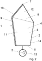
- the aerodynamic structure 1 is shown in a perspective plan view.
- the wing-like shape 2 of the aerodynamic structure 1 has an upper side 3 and a lower side 4 with a profile nose 10 and a thickening 9, the thickening 9 being located on the upper side 3 remote from the gas and / or wind.
- the wing-like shape 2 has a geometry of a general quadrilateral 11 from the root 6, to which a triangular geometry 12 adjoins the root 6 opposite side of the general quadrilateral 11 and wherein the triangular geometry 12 in the direction of the tip 7 of the wing-like Form 2 points.
- a thickening 9 is arranged, which is designed sharp-edged.
- the transition from the sharp-edged thickening 9 to the top 3 of the flat surface 8 is chosen so that a wind edge is formed.
- the geometry of the thickening 9 follows the entire contour of the side facing away from the wind of the wing-like mold 2, ie, the contour of the thickening 9 extends over the entire span of the wing-like mold 2. The thus generated stall in a rotation is thus complete along the entire length of the thickening 9 of the wing-like shape 2.
- FIG. 3 the movement or the direction of movement of the vertebrae on the wing-like shape 2 of the aerodynamic structure 1 is shown.
- a vortex or a vortex-like gas or air movement arises on the upper side 3 of the flat surface 8.
- the vortex spreads on the flat surface 8 and tears open air the top 3 of the wing-like mold 2 with.
- the vortices move in the direction of the profile trailing edge 14 during rotation and leave the flat surface 8 in the region of the profile trailing edge 14 of the triangular structure 12.
Landscapes
- Engineering & Computer Science (AREA)
- Mechanical Engineering (AREA)
- Fluid Mechanics (AREA)
- Physics & Mathematics (AREA)
- Aviation & Aerospace Engineering (AREA)
- Sustainable Development (AREA)
- Sustainable Energy (AREA)
- Chemical & Material Sciences (AREA)
- Combustion & Propulsion (AREA)
- Life Sciences & Earth Sciences (AREA)
- General Engineering & Computer Science (AREA)
- Wind Motors (AREA)
- Structures Of Non-Positive Displacement Pumps (AREA)
Abstract
Description
- Die Erfindung betrifft eine aerodynamische Struktur, umfassend mindestens eine flügelartige Form mit Ober- und Unterseite, die eine Rotationsachse aufweist, in die ein Lager eingelassen ist, welches über eine Welle mit einer Achse verbunden ist, wobei sich von der Wurzel der flügelartigen Form bis zur Spitze eine ebene Fläche aufspannt, ein Verfahren zur Herstellung der aerodynamischen Struktur, sowie die Verwendung der aerodynamischen Struktur in Windturbinen, Abgasturboladern oder Hubschraubern.
- Die Konstruktion von Rotorblättern hat in den letzten Jahren ein breites Anwendungsfeld gefunden, sei es im Bereich der Stromerzeugung in Windturbinen oder im Bereich von Hubschraubern oder Turboladern. Die Konstruktionen haben gemeinsam, dass sie Rotorblätter aufweisen mit deren Hilfe die Strömungsenergie eines Gasgemisches in mechanische Energie umgewandelt werden kann.
- So werden Windturbinen bereits seit längerer Zeit zur Stromerzeugung genutzt, wobei die Form und die Gestaltung der Komponenten wie Gondel, Rotorblätter und Turm Gegenstand vieler Untersuchungen gewesen ist. Die Rotorblätter sind nach dem Stand der Technik derart profiliert, dass eine Druckdifferenz zwischen Ober- und Unterseite der Rotorblätter erzeugt und in der Folge die Windturbine in Rotation versetzt wird.
- Bei Hubschrauberflügeln wird die Rotation durch einen Motor erzeugt, wobei an den Flügeln ebenfalls ein Druckunterschied zwischen Ober- und Unterseite herrscht, was letztlich dazu führt, dass der Hubschrauber nach oben "gehoben" oder besser nach oben "gedrückt" wird.
- Die konstruktive Ausgestaltung von Rotorblättern ist im Stand der Technik bereits eingehend beschrieben worden und orientiert sich immer mehr an den Vorlagen der Natur. Der Stand der Technik beschreibt zahlreiche strömungsbeeinflussende Maßnahmen zur Erzeugung von Auftrieb und zur weiteren Beherrschung der sich ergebenden Strömung. So ist ein bionischer Ansatz aufgrund einer Walflosse in der
DE 10 2011 056 342 A1 offenbart. - In der
AT 137 005 B - Die
DE 103 00 284 A1 offenbart ein Rotorblatt für eine Windenergieanlage, mit einem eine Rotorblattvorderkante und eine Rotorblatthinterkante aufweisenden aerodynamischen Profil, wobei die Rotorblattspitze in ihrem Endbereich in Richtung der Druckseite des Rotorblattes abgebogen oder abgewinkelt ist. Ferner sind in derDE 103 002 84 Merkmale verschiedenförmiger Wölbungen und Richtungen in Erstreckungsrichtung eines Rotorblatts in der Längsachse beschrieben, ebenso wie verschiedenförmige geometrische Ausführungen der Blattspitze. - Das Problem bei der Konstruktion von Rotorblättern nach dem Stand der Technik ist jedoch, dass neben den Kosten für die Herstellung der Rotorblätter die bestehenden Anlagen lediglich einen Wirkungsgrad von 40-50% ermöglichen, wobei der Grund dafür hauptsächlich durch aerodynamische Verluste wie Luftreibung an den Blättern, Wirbelschleppen an den Blattspitzen und durch Drall im Nachlauf des Rotors hervorgerufen wird. Um den Wirkungsgrad von Windturbinen, Abgasturboladern und Hubschraubern durch Änderungen der Rotorgeometrie zu verbessern, muss die Konstruktion daher so ausgestaltet werden, dass der durch die Rotoren induzierte Auftrieb verbessert wird oder die aerodynamischen Verluste verringert werden.
- Aufgabe der Erfindung ist es daher Rotorblätter für Turbinen, Abgasturbolader und Hubschrauber bereit zu stellen, die kostengünstiger in der Herstellung sind und dabei einen höheren Wirkungsgrad der Anlagen ermöglichen als mit den bereits bekannten Formen, wobei die Formen mit bestehenden Anlagen kompatibel sein sollen.
- Die Aufgabe wird erfindungsgemäß durch eine aerodynamische Struktur mit den Merkmalen des unabhängigen Anspruchs 1 oder durch ein Verfahren mit den Merkmalen des unabhängigen Anspruchs 14 gelöst.
- Erfindungsgemäß ist vorgesehen eine aerodynamische Struktur bereit zu stellen, die mindestens eine flügelartige Form mit Ober- und Unterseite mit einer Rotationsachse aufweist, wobei in die Rotationsachse ein Lager eingelassen ist, das über eine Welle mit einer Achse verbunden ist, wobei sich von der Wurzel der flügelartigen Form bis zur Spitze eine ebene Fläche aufspannt.
- Unter aerodynamischer Struktur soll vorliegend eine geometrische Form zu verstehen sein, die als flügelartige Form in gas- und luftbasierten Konstruktionen als Teil eines Rotors Anwendung findet, wobei die Strömungsenergie eines Gasmediums zur Energieerzeugung im nahezu optimalen Bereich des Betz-Koeffizienten genutzt werden kann.
- Die erfindungsgemäße Konstruktion sieht vor, dass die flügelartige Form eine Profilnase mit einer Verdickung auf der dem Gas und/oder Wind abgewandten Oberseite aufweist und eine Geometrie eines allgemeinen Vierecks ausgehend von der Wurzel der Form umfasst, wobei sich eine dreieckige Geometrie an eine der Seiten des Vierecks zur Spitze der Form anschließt. Es ist in der Regel vorgesehen, dass die dreieckige Geometrie sich an die Seite des Vierecks anschließt, die der Wurzel der Form gegenüber liegt. Es ist jedoch auch möglich, dass sich die dreieckige Geometrie der Seite anschließt, die zur Wurzel der Form direkt benachbart liegt. Es hat sich aber gezeigt, dass die Wahl des Typs, bei der sich die dreieckige Geometrie der gegenüberliegenden Seite der Wurzel der Form anschließt, bei einer Rotation der Struktur um die Rotationsachse den größten permanenten Unterdruck auf der Oberseite der flügelartigen Form generiert. Insofern orientiert sich die erfindungsgemäße Form in der Regel an dieser Ausgestaltung, wenn nicht besondere Ausgestaltungen der Struktur mit im Ergebnis verringertem Auftrieb resultieren sollen.
- Wird die Struktur durch eine Windbewegung in Rotation versetzt, so entsteht ein Wirbel oder eine wirbelartige Gas- oder Luftbewegung auf der Oberseite der Form, d.h. auf der ebenen Fläche. Der Wirbel breitet sich in der Folge auf der ebenen Fläche aus und reißt Luft auf der Oberfläche mit. Es wurde in diesem Zusammenhang festgestellt, dass je vollständiger sich der Wirbel oder die wirbelartige Gas- oder Luftbewegung auf der Oberfläche der ebenen Fläche ausbreitet, der generierte Unterdruck wächst und der so erzeugte Auftrieb größer wird.
- An der dem Wind abgewandten Oberseite der Form ist erfindungsgemäß vorgesehen, dass eine Verdickung vorhanden ist, die scharfkantig ausgestaltet ist und insbesondere viereckig oder dreieckig ist. Eine scharfkantige Ausgestaltung bedeutet in diesem Zusammenhang, dass ein Übergang von der scharfkantigen Verdickung zur Oberfläche der ebenen Fläche so gewählt wird, dass ein Strömungsabbruch auf der dem Wind abgewandten Seite generiert wird, d.h. eine Windkante entsteht. Die Höhe der Verdickung gegenüber der ebenen Fläche beträgt dabei mindestens das Doppelte der Dicke der ebenen Fläche. In einer besonders vorteilhaften Ausgestaltung ist dabei insbesondere vorgesehen, dass die Geometrie der Verdickung der gesamten Kontur der dem Wind abgewandten Seite der Form folgt, d.h. dass die Kontur der Verdickung sich über die gesamte Spannweite der Form erstreckt und damit entlang der gesamten Kontur des allgemeinen Vierecks und der dreieckigen Geometrie ein Strömungsabriss erfolgt. Der damit erzeugte Strömungsabriss erfolgt somit vollständig entlang der gesamten Länge der Verdickung.
- Es hat sich für die Optimierung des Auftriebs als besonders vorteilhaft herausgestellt die Geometrie der flügelartigen Form so zu wählen, dass mindestens 50% von der gesamten Spannweite der Form von der Geometrie des allgemeinen Vierecks umfasst sind, wobei die Geometrie sich der Art nach an einer ellipsenförmigen, ahornsamenähnlichen Fläche orientiert. Es hat sich gezeigt, dass der Auftrieb dann am Größten ist, wenn die Seite des Vierecks an der Profilnase länger ist als an der Profilkante. Dies soll deswegen erfolgen, damit sich eine annähernd ahornsamenförmige Geometrie ausbildet. Die Herstellung einer vollständig ahornsamenförmigen Struktur ist jedoch durch die ellipsenartige Rundung schwierig und kostenintensiv, sodass die aerodynamische Struktur eine Geometrie aufweist, die einfacher und kostengünstiger herstellbar ist als die der Natur vollständig nachempfundene Form, wobei die Geometrie so gewählt wird, dass die Vorteile der einfacheren Herstellung der erfindungsgemäßen Form mit den Vorteilen der Form aus der Natur kombiniert werden.
- So ist in einer weiteren vorteilhaften Ausgestaltung vorgesehen, dass die Geometrie der Form eines allgemeinen Vierecks durch eine trapezförmige Geometrie ersetzt ist. Der Vorteil der trapezförmigen Ausgestaltung eines Teils der gesamten Spannweite der Form ist, dass eine parallele Anordnung zweier Seiten eine einfachere Herstellung der erfindungsgemäßen Form gewährleistet wird. Dabei soll das Verhältnis der kurzen Seite der trapezförmigen Geometrie gegenüber der langen Seite einen Wert von 2:3 betragen.
- Ferner hat es sich als besonders vorteilhaft herausgestellt, dass sich die Winkel der flügelartigen Form in Bezug auf die Rotationsachse und/oder der Windrichtung in Abhängigkeit von der Windgeschwindigkeit ändern können. Eine solche Ausrichtung hat insbesondere zu Beginn des Betriebs einer Anlage zu erfolgen, da sich die Form so in die Richtung der Luft- und/oder Gasströmung auszurichten hat, dass ein Strömungsabriss an der Verdickung an der dem Wind oder Gasmischung zugewandten Kante der Form erfolgt. Je nachdem wie groß die Strömungsenergie ist, muss sich die Form so ausrichten, dass der durch den induzierten Strömungsabriss erzielte Drehmoment zu Beginn des Betriebs der Anlage nicht zu groß ist, um ein Taumeln des Rotors zu vermeiden. Die Form wird dabei langsam in den Gasstrom gedreht. Dies erfolgt analog dem Pitch Control Prinzip aus den bekannten Rotorblättern nach dem Stand der Technik.
- Die Kompatibilität der erfindungsgemäßen Form zu den Formen nach dem Stand der wird durch flächige Aufnahmen an der Nabe als Rotor- oder Turbinenblatt gewährleistet. Flächige Aufnahme bedeutet in diesem Zusammenhang eine Befestigungsmöglichkeit beispielsweise über Flansche mit Schrauben der Rotorblätter an der Nabe der Konstruktion gewährleistet wird.
- Da auf die Form strömungsabhängig starke Kräfte einwirken können, muss die ebene Fläche, die sich von der Wurzel der flügelartigen Form bis zur Spitze aufspannt, elastisch ausgestaltet sein. Unter Elastizität ist vorliegend gemeint, dass die Fläche unter Krafteinwirkung ihre Form zwar verändert, aber bei Wegfall der einwirkenden Kraft in ihre Ursprungsform zurückkehrt. Dies ist insbesondere wichtig, damit sich die Rotorblätter zwar biegen können, aber den auftreffenden Kräften so nachgeben, dass ein Wirbel oder eine wirbelartige Gas- oder Luftbewegung auf der Form, insbesondere auf der ebenen Fläche auch bei hohen einwirkenden Kräften während des gesamten Betriebs gewährleistet bleibt.
- Die ebene Fläche ist an der Profilnase der Form so befestigt, dass diese zumindest mit einem Teilbereich kraftschlüssig und/oder formschlüssig verbunden ist. Unter Kraft- und/oder Formschluss ist zu verstehen, dass die ebene Fläche im Bereich der Verdickung befestigt ist, sei es, dass sie verklemmt, verklebt, verschraubt, nach dem Nut/Feder-Prinzip befestigt oder mit Hilfe von Splinten gehalten wird.
- Das Material der ebenen Fläche und/oder der Form, sowie der gesamten Struktur im Allgemeinen umfasst dabei Kunststoffe, Metalle, Holz oder Verbundstoffe, sowie Mischungen dieser Stoffe. Unter Kunststoffen sind alle plastisch verformbaren Materialien, wie PE, PVC, PEEK etc. oder auch Karbonfasern zu verstehen. Metalle umfassen Verbindungen von Eisen, Chrom, Nickel, Mangan, Aluminium, Legierungen wie Messing, Bronze etc. Holz umfasst Hölzer wie Ahorn, Pappel, Fichte, Buche oder auch Verbundstoffe wie kohlefaserverstärkte Materialverbünde, insbesondere solche die aus sogenannten Pre-Prags hergestellt sind. Alle voran stehenden Verbindungen weisen dabei eine Elastizität auf, die eine Auslenkung der ebenen Fläche aufgrund linearer oder nicht-linear elastischer Verformung ermöglichen.
- Es hat sich dabei insbesondere herausgestellt, dass die Oberfläche der ebenen Fläche durch Aufrauen oder durch Anordnung von Faserlinien bewirkt, dass die rotations- und windkanteninduzierten Wirbel oder wirbelförmigen Gas- und/oder Luftbewegungen sich besser auf der Oberfläche verteilen können bzw. eine Ausbreitung unterstützen oder eine gleichmäßigere Bewegung und Verteilung der Wirbel ermöglichen. Es ist zu vermuten, dass durch das Aufrauen oder die Anordnung der Faserlinien ein verbesserter Auftrieb gegenüber einer faserlinienfreien Form erreicht wird. Das Verfahren zur Herstellung umfasst dabei insbesondere den Fall, dass mit Hilfe einer Nut-Feder-Verbindung oder mit Hilfe von Splinten die elastische Fläche an dem Bereich der Profilnase befestigt wird.
- Die erfindungsgemäße Struktur und das Verfahren zu dessen Herstellung werden insbesondere in Anwendungsgebieten zum Einsatz gebracht, die Windturbinen, Abgasturbolader oder Hubschraubern umfassen. Dabei kann Strömungsenergie in mechanische Energie und/oder mit Hilfe eines Generators in elektrische Energie umgewandelt werden.
- Die Erfindung wird anhand der nachfolgenden Figuren nochmals eingehend beschrieben.
-
Figur 1 zeigt die aerodynamische Struktur 1 mit Oberseite 3 und Unterseite 4 in einem vertikalen Querschnitt zur Rotationsachse 5. Man erkennt einenends des Querschnitts die Profilnase 10, die eine Verdickung 9 aufweist. Anderenends des Querschnitts ist die Profilhinterkante 14 zu erkennen, die gegenüber der Verdickung 9 an der Profilnase 10 einen geringeren Umfang einnimmt. - In
Figur 2 ist die aerodynamische Struktur 1 in einer perspektivischen Aufsicht dargestellt. Die flügelartige Form 2 der aerodynamischen Struktur 1 weist eine Oberseite 3 und eine Unterseite 4 mit einer Profilnase 10 und einer Verdickung 9 auf, wobei sich die Verdickung 9 an der einem Gas und/oder Wind abgewandten Oberseite 3 befindet. Die flügelartige Form 2 weist eine Geometrie eines allgemeinen Vierecks 11 ausgehend von der Wurzel 6 auf, an die sich eine dreieckige Geometrie 12 an der der Wurzel 6 gegenüberliegenden Seite des allgemeinen Vierecks 11 anschließt und wobei die dreieckige Geometrie 12 in Richtung der Spitze 7 der flügelartigen Form 2 weist. An der dem Wind abgewandten Oberseite 3 der flügelartigen Form 2 ist eine Verdickung 9 angeordnet, die scharfkantig ausgestaltet ist. Der Übergang von der scharfkantigen Verdickung 9 zur Oberseite 3 der ebenen Fläche 8 ist dabei so gewählt wird, dass eine Windkante entsteht. In der vorliegenden Darstellung folgt die Geometrie der Verdickung 9 der gesamten Kontur der dem Wind abgewandten Seite der flügelartigen Form 2, d.h. die Kontur der Verdickung 9 erstreckt sich über die gesamte Spannweite der flügelartigen Form 2. Der damit erzeugbare Strömungsabriss bei einer Rotation erfolgt somit vollständig entlang der gesamten Länge der Verdickung 9 der flügelartigen Form 2. Wird die aerodynamische Struktur 1 durch eine Windbewegung in Rotation um die in einer Aufnahme 13 gelagerten Rationsachse 5 versetzt, so entsteht ein Wirbel oder eine wirbelartige Gas- oder Luftbewegung auf der Oberseite 3 der flügelartigen Form 2, die sich in Richtung der Profilhinterkante 14 bewegt. - In
Figur 3 ist die Bewegung bzw. die Bewegungsrichtung der Wirbel auf der flügelartigen Form 2 der aerodynamischen Struktur 1 dargestellt. Wird die aerodynamische Struktur 1 durch eine Windbewegung in Rotation um die Rotationsachse 5 versetzt, so entsteht ein Wirbel oder eine wirbelartige Gas- oder Luftbewegung auf der Oberseite 3 der ebenen Fläche 8. Der Wirbel breitet sich auf der ebenen Fläche 8 aus und reißt Luft auf der Oberseite 3 der flügelartigen Form 2 mit. Die Wirbel bewegen sich bei der Rotation in Richtung der Profilhinterkante 14 und verlassen die ebene Fläche 8 im Bereich der Profilhinterkante 14 der dreieckigen Struktur 12. Je vollständiger sich der Wirbel oder die wirbelartige Gas- oder Luftbewegung auf der Oberseite 3 der ebenen Fläche 8 ausbreitet, desto mehr wächst der generierte Unterdruck und desto größer wird der erzeugte Auftrieb. -
- 1
- aerodynamische Struktur
- 2
- flügelartige Form
- 3
- Oberseite
- 4
- Unterseite
- 5
- Rotationsache
- 6
- Wurzel
- 7
- Spitze
- 8
- Ebene Fläche
- 9
- Verdickung
- 10
- Profilnase
- 11
- Geometrie allgemeines Viereck
- 12
- Dreieckige Geometrie
- 13
- Aufnahme
- 14
- Profilhinterkante
Claims (16)
- Aerodynamische Struktur (1), umfassend mindestens eine flügelartige Form (2) mit Ober- (3) und Unterseite (4), die eine Rotationsachse (5) aufweist, in die ein Lager eingelassen und das über eine Welle mit einer Achse verbunden ist, wobei sich von der Wurzel (6) der flügelartigen Form (2) bis zur Spitze (7) eine ebene Fläche (8) aufspannt, dadurch gekennzeichnet, dass eine Verdickung (9) im Bereich der Profilnase (10) auf der dem Wind abgewandten Oberseite (3) umfasst, die ebene Fläche (8) die Geometrie eines allgemeinen Vierecks (11) von der Wurzel (6) der Form (2) aufweist und an eine der Seiten sich eine dreieckige Geometrie (12) zur Spitze (7) der Form (2) anschließt.
- Aerodynamische Struktur (1) nach Anspruch 1,
dadurch gekennzeichnet, dass von der gesamten Spannweite der Form (2) die Geometrie des allgemeinen Vierecks (11) mindestens 50% einnimmt. - Aerodynamische Struktur (1) nach Anspruch 1 oder 2,
dadurch gekennzeichnet, dass die Verdickung (9) scharfkantig ist. - Aerodynamische Struktur (1) nach einem der Ansprüche 1 bis 3,
dadurch gekennzeichnet, dass die Verdickung (9) viereckig oder dreieckig ist. - Aerodynamische Struktur (1) nach einem der Ansprüche 1 bis 4,
dadurch gekennzeichnet, dass die Verdickung (9) der Geometrie des allgemeinen Vierecks (11) und der dreieckigen Geometrie (12) der gesamten Spannweite der Form (2) in der Kontur folgt. - Aerodynamische Struktur (1) nach einem der Ansprüche 1 bis 5,
dadurch gekennzeichnet, dass die Geometrie der Form (2) eines allgemeinen Vierecks (11) durch eine trapezförmige Geometrie ersetzt ist. - Aerodynamische Struktur (1) nach Anspruch 6,
dadurch gekennzeichnet, dass das Verhältnis der kurzen Seite der trapezförmigen Geometrie gegenüber der langen Seite einen Wert von 2:3 aufweist. - Aerodynamische Struktur (1) nach einem der Ansprüche 1 bis 7,
dadurch gekennzeichnet, dass sich die Winkel der flügelartigen Form (2) in Bezug auf die Rotationsachse (5) und/oder der Richtung der gasförmigen Strömung in Abhängigkeit von der Strömungsgeschwindigkeit ändern. - Aerodynamische Struktur (1) nach einem der Ansprüche 1 bis 8,
dadurch gekennzeichnet, dass die Form (2) Aufnahmen (13) zur Befestigung als Rotor- oder Turbinenblatt aufweist. - Aerodynamische Struktur (1) nach einem der Ansprüche 1 bis 9,
dadurch gekennzeichnet, dass die ebene Fläche (8) elastisch ausgestaltet ist. - Aerodynamische Struktur (1) nach einem der Ansprüche 1 bis 10,
dadurch gekennzeichnet, dass die ebene Fläche (8) zumindest mit einem Teilbereich der Profilnase (10) kraftschlüssig und/oder formschlüssig verbunden ist. - Aerodynamische Struktur (1) nach einem der Ansprüche 1 bis 11,
dadurch gekennzeichnet, dass das Material für die Form (2) Kunststoffe, Metalle, Holz oder Verbundstoffe umfasst. - Aerodynamische Struktur (1) nach einem der Ansprüche 1 bis 12 dadurch gekennzeichnet, dass Faserlinien auf der ebenen Fläche (8) vorhanden sind.
- Verfahren zur Herstellung einer aerodynamischen Struktur (1) umfassend mindestens eine flügelartige Form (2) mit Ober-(3) und Unterseite (4), wobei die Form (2) eine Rotationsachse (5) aufweist, in die ein Lager eingelassen und über das eine Welle mit einer Achse verbunden ist, wobei von der Form (2) der Wurzel (6) bis zur Spitze (7) der Form (2) eine ebene Fläche (8) aufgespannt wird,
dadurch gekennzeichnet, dass der Bereich der Profilnase (10) auf der dem Wind abgewandten Oberseite (4) verdickt und die ebene Fläche (8) zumindest mit einem Teilbereich der Profilnase (10) kraftschlüssig und/oder formschlüssig verbunden wird, wobei bei einer Rotation der Form (2) um ihre Rotationsachse (5) ein permanenter Unterdruck auf der Oberseite (4) der Form (2) erzeugt wird. - Verfahren nach Anspruch 14,
dadurch gekennzeichnet, dass die ebene Fläche (8) zumindest mit einem Teilbereich der Profilnase (10) mit Hilfe einer Führungsnut verbunden wird. - Verwendung einer aerodynamischen Struktur (1) nach einem der Ansprüche 1 bis 13, zum Einsatz in Windturbinen, Abgasturboladern oder Hubschraubern.
Priority Applications (1)
| Application Number | Priority Date | Filing Date | Title |
|---|---|---|---|
| SI201831221T SI3421783T1 (sl) | 2017-06-28 | 2018-06-28 | Aerodinamična struktura |
Applications Claiming Priority (1)
| Application Number | Priority Date | Filing Date | Title |
|---|---|---|---|
| DE102017114414.5A DE102017114414B3 (de) | 2017-06-28 | 2017-06-28 | Aerodynamische Struktur, Verfahren zur Herstellung und Verwendung einer solchen |
Publications (2)
| Publication Number | Publication Date |
|---|---|
| EP3421783A1 true EP3421783A1 (de) | 2019-01-02 |
| EP3421783B1 EP3421783B1 (de) | 2024-12-18 |
Family
ID=62568391
Family Applications (1)
| Application Number | Title | Priority Date | Filing Date |
|---|---|---|---|
| EP18180274.5A Active EP3421783B1 (de) | 2017-06-28 | 2018-06-28 | Aerodynamische struktur |
Country Status (3)
| Country | Link |
|---|---|
| EP (1) | EP3421783B1 (de) |
| DE (1) | DE102017114414B3 (de) |
| SI (1) | SI3421783T1 (de) |
Citations (11)
| Publication number | Priority date | Publication date | Assignee | Title |
|---|---|---|---|---|
| AT137005B (de) | 1930-10-21 | 1934-04-10 | Joseph Jeremiah Callahan | Mehrflügelige Treibschraube. |
| US4693673A (en) * | 1982-08-09 | 1987-09-15 | Nee Victor W | Ceiling fan |
| DE10300284A1 (de) | 2003-01-02 | 2004-07-15 | Aloys Wobben | Rotorblatt für eine Windenergieanlage |
| CN2818834Y (zh) * | 2005-08-31 | 2006-09-20 | 郑冠雄 | 风力发电机 |
| CN101042147A (zh) * | 2006-03-24 | 2007-09-26 | 谢秉缙 | 风扇叶的制造方法及依此方法制成的产品 |
| US20080253896A1 (en) * | 2007-04-13 | 2008-10-16 | Walls Gary C | High efficiency fan blades with airflow-directing baffle elements |
| EP2028366A2 (de) * | 2007-05-31 | 2009-02-25 | Gamesa Innovation & Technology, S.L. | Windturbinenschaufel mit Geräuschdämpfungselementen |
| DE102011056342A1 (de) | 2010-12-13 | 2012-07-19 | General Electric Company | Verfahren zur Herstellung von Rotorflügeln für eine Windkraftanlage |
| MX2011013994A (es) * | 2011-12-16 | 2013-06-17 | Univ Autonoma De Tamaulipas | Rotor de eje vertical con palas de perfil de ala plana. |
| WO2016019466A1 (en) * | 2014-08-05 | 2016-02-11 | Ryan Church | Fluid-redirecting structure |
| US20170174318A1 (en) * | 2015-12-18 | 2017-06-22 | Amazon Technologies, Inc. | Propeller blade indentations for improved aerodynamic performance and sound control |
Family Cites Families (1)
| Publication number | Priority date | Publication date | Assignee | Title |
|---|---|---|---|---|
| US6352408B1 (en) * | 2000-10-16 | 2002-03-05 | Robert B. Kilian | Slip inhibiting boat propeller |
-
2017
- 2017-06-28 DE DE102017114414.5A patent/DE102017114414B3/de active Active
-
2018
- 2018-06-28 EP EP18180274.5A patent/EP3421783B1/de active Active
- 2018-06-28 SI SI201831221T patent/SI3421783T1/sl unknown
Patent Citations (11)
| Publication number | Priority date | Publication date | Assignee | Title |
|---|---|---|---|---|
| AT137005B (de) | 1930-10-21 | 1934-04-10 | Joseph Jeremiah Callahan | Mehrflügelige Treibschraube. |
| US4693673A (en) * | 1982-08-09 | 1987-09-15 | Nee Victor W | Ceiling fan |
| DE10300284A1 (de) | 2003-01-02 | 2004-07-15 | Aloys Wobben | Rotorblatt für eine Windenergieanlage |
| CN2818834Y (zh) * | 2005-08-31 | 2006-09-20 | 郑冠雄 | 风力发电机 |
| CN101042147A (zh) * | 2006-03-24 | 2007-09-26 | 谢秉缙 | 风扇叶的制造方法及依此方法制成的产品 |
| US20080253896A1 (en) * | 2007-04-13 | 2008-10-16 | Walls Gary C | High efficiency fan blades with airflow-directing baffle elements |
| EP2028366A2 (de) * | 2007-05-31 | 2009-02-25 | Gamesa Innovation & Technology, S.L. | Windturbinenschaufel mit Geräuschdämpfungselementen |
| DE102011056342A1 (de) | 2010-12-13 | 2012-07-19 | General Electric Company | Verfahren zur Herstellung von Rotorflügeln für eine Windkraftanlage |
| MX2011013994A (es) * | 2011-12-16 | 2013-06-17 | Univ Autonoma De Tamaulipas | Rotor de eje vertical con palas de perfil de ala plana. |
| WO2016019466A1 (en) * | 2014-08-05 | 2016-02-11 | Ryan Church | Fluid-redirecting structure |
| US20170174318A1 (en) * | 2015-12-18 | 2017-06-22 | Amazon Technologies, Inc. | Propeller blade indentations for improved aerodynamic performance and sound control |
Also Published As
| Publication number | Publication date |
|---|---|
| EP3421783B1 (de) | 2024-12-18 |
| DE102017114414B3 (de) | 2018-07-05 |
| SI3421783T1 (sl) | 2025-05-30 |
Similar Documents
| Publication | Publication Date | Title |
|---|---|---|
| DE102011052930C5 (de) | Blattansatzstück für Rotorblätter in Windkraftanlagen | |
| DE102011056491B4 (de) | Lärmreduziereinrichtung für ein Rotorblatt in einer Windkraftanlage | |
| DE10201726B4 (de) | Windenergieanlage | |
| DE102011051831B4 (de) | Rotorblatt für eine Windkraftanlage mit einem Saugseitenwinglet | |
| EP2339171B1 (de) | Rotorblatt für eine Windkraftanlage | |
| DE102011055023A1 (de) | Lärmreduziereinrichtung für ein Rotorblatt in einer Windkraftanlage | |
| DE102009025857A1 (de) | Windmaschinenrotorflügel-Grundrisse mit verdrehten und sich verjüngenden Spitzen | |
| DE102008002930A1 (de) | Rotorflügel-Spitzenwirbelbrecher | |
| DE102012100593A1 (de) | Steuerbare Oberflächenmerkmale für Rotorblätter von Windkraftanlagen | |
| DE102011056353A1 (de) | Windturbinenrotorblatt | |
| DE102013207640B4 (de) | Windenergieanlagen-Rotorblatt | |
| DE102012109171A1 (de) | Windkraftanlagenrotorblatt mit passiv modifizierter Abströmkantenkomponente | |
| EP1514023A1 (de) | Rotorblatt einer windenergieanlage | |
| DE102011050777A1 (de) | Rotor und Rotorblatt für eine Windkraftanlage | |
| EP3399183B1 (de) | Rotorblatt einer windenergieanlage | |
| DE4030559C2 (de) | ||
| DE102017114414B3 (de) | Aerodynamische Struktur, Verfahren zur Herstellung und Verwendung einer solchen | |
| EP3981981A1 (de) | Rotorblatt für eine windenergieanlage, windenergieanlage und verfahren zur auslegung eines rotorblatts | |
| EP3844384B1 (de) | Rotor mit rotorblatt, windenergieanlage und verfahren zum optimieren einer windenergieanlage | |
| EP4577738B1 (de) | Rotorblatt für eine windenergieanlage sowie rotorblattspitze | |
| DE102017112384A1 (de) | Vertikale Windkraftanlage | |
| EP3954892A2 (de) | Rotorblatt für eine windenergieanlage, rotor für eine windenergieanlage, bauwerk und windenergieanlage | |
| DE102015102461A1 (de) | Windkraftanlage mit Vorstage an den Rotorblättern | |
| EP4671529A1 (de) | Rotorblatt umfassend elastikelement, verfahren und windenergieanlage | |
| DE102011050462A1 (de) | Windkraftanlage |
Legal Events
| Date | Code | Title | Description |
|---|---|---|---|
| PUAI | Public reference made under article 153(3) epc to a published international application that has entered the european phase |
Free format text: ORIGINAL CODE: 0009012 |
|
| STAA | Information on the status of an ep patent application or granted ep patent |
Free format text: STATUS: THE APPLICATION HAS BEEN PUBLISHED |
|
| AK | Designated contracting states |
Kind code of ref document: A1 Designated state(s): AL AT BE BG CH CY CZ DE DK EE ES FI FR GB GR HR HU IE IS IT LI LT LU LV MC MK MT NL NO PL PT RO RS SE SI SK SM TR |
|
| AX | Request for extension of the european patent |
Extension state: BA ME |
|
| STAA | Information on the status of an ep patent application or granted ep patent |
Free format text: STATUS: REQUEST FOR EXAMINATION WAS MADE |
|
| 17P | Request for examination filed |
Effective date: 20190628 |
|
| RBV | Designated contracting states (corrected) |
Designated state(s): AL AT BE BG CH CY CZ DE DK EE ES FI FR GB GR HR HU IE IS IT LI LT LU LV MC MK MT NL NO PL PT RO RS SE SI SK SM TR |
|
| STAA | Information on the status of an ep patent application or granted ep patent |
Free format text: STATUS: EXAMINATION IS IN PROGRESS |
|
| 17Q | First examination report despatched |
Effective date: 20211007 |
|
| GRAP | Despatch of communication of intention to grant a patent |
Free format text: ORIGINAL CODE: EPIDOSNIGR1 |
|
| STAA | Information on the status of an ep patent application or granted ep patent |
Free format text: STATUS: GRANT OF PATENT IS INTENDED |
|
| INTG | Intention to grant announced |
Effective date: 20240708 |
|
| GRAS | Grant fee paid |
Free format text: ORIGINAL CODE: EPIDOSNIGR3 |
|
| GRAA | (expected) grant |
Free format text: ORIGINAL CODE: 0009210 |
|
| STAA | Information on the status of an ep patent application or granted ep patent |
Free format text: STATUS: THE PATENT HAS BEEN GRANTED |
|
| AK | Designated contracting states |
Kind code of ref document: B1 Designated state(s): AL AT BE BG CH CY CZ DE DK EE ES FI FR GB GR HR HU IE IS IT LI LT LU LV MC MK MT NL NO PL PT RO RS SE SI SK SM TR |
|
| REG | Reference to a national code |
Ref country code: GB Ref legal event code: FG4D Free format text: NOT ENGLISH |
|
| REG | Reference to a national code |
Ref country code: CH Ref legal event code: EP |
|
| REG | Reference to a national code |
Ref country code: DE Ref legal event code: R096 Ref document number: 502018015419 Country of ref document: DE |
|
| REG | Reference to a national code |
Ref country code: IE Ref legal event code: FG4D Free format text: LANGUAGE OF EP DOCUMENT: GERMAN |
|
| REG | Reference to a national code |
Ref country code: LT Ref legal event code: MG9D |
|
| PG25 | Lapsed in a contracting state [announced via postgrant information from national office to epo] |
Ref country code: HR Free format text: LAPSE BECAUSE OF FAILURE TO SUBMIT A TRANSLATION OF THE DESCRIPTION OR TO PAY THE FEE WITHIN THE PRESCRIBED TIME-LIMIT Effective date: 20241218 |
|
| PG25 | Lapsed in a contracting state [announced via postgrant information from national office to epo] |
Ref country code: FI Free format text: LAPSE BECAUSE OF FAILURE TO SUBMIT A TRANSLATION OF THE DESCRIPTION OR TO PAY THE FEE WITHIN THE PRESCRIBED TIME-LIMIT Effective date: 20241218 |
|
| PG25 | Lapsed in a contracting state [announced via postgrant information from national office to epo] |
Ref country code: BG Free format text: LAPSE BECAUSE OF FAILURE TO SUBMIT A TRANSLATION OF THE DESCRIPTION OR TO PAY THE FEE WITHIN THE PRESCRIBED TIME-LIMIT Effective date: 20241218 |
|
| PG25 | Lapsed in a contracting state [announced via postgrant information from national office to epo] |
Ref country code: NO Free format text: LAPSE BECAUSE OF FAILURE TO SUBMIT A TRANSLATION OF THE DESCRIPTION OR TO PAY THE FEE WITHIN THE PRESCRIBED TIME-LIMIT Effective date: 20250318 |
|
| REG | Reference to a national code |
Ref country code: NL Ref legal event code: MP Effective date: 20241218 |
|
| PG25 | Lapsed in a contracting state [announced via postgrant information from national office to epo] |
Ref country code: LV Free format text: LAPSE BECAUSE OF FAILURE TO SUBMIT A TRANSLATION OF THE DESCRIPTION OR TO PAY THE FEE WITHIN THE PRESCRIBED TIME-LIMIT Effective date: 20241218 Ref country code: GR Free format text: LAPSE BECAUSE OF FAILURE TO SUBMIT A TRANSLATION OF THE DESCRIPTION OR TO PAY THE FEE WITHIN THE PRESCRIBED TIME-LIMIT Effective date: 20250319 |
|
| PG25 | Lapsed in a contracting state [announced via postgrant information from national office to epo] |
Ref country code: RS Free format text: LAPSE BECAUSE OF FAILURE TO SUBMIT A TRANSLATION OF THE DESCRIPTION OR TO PAY THE FEE WITHIN THE PRESCRIBED TIME-LIMIT Effective date: 20250318 |
|
| PG25 | Lapsed in a contracting state [announced via postgrant information from national office to epo] |
Ref country code: NL Free format text: LAPSE BECAUSE OF FAILURE TO SUBMIT A TRANSLATION OF THE DESCRIPTION OR TO PAY THE FEE WITHIN THE PRESCRIBED TIME-LIMIT Effective date: 20241218 |
|
| PG25 | Lapsed in a contracting state [announced via postgrant information from national office to epo] |
Ref country code: SM Free format text: LAPSE BECAUSE OF FAILURE TO SUBMIT A TRANSLATION OF THE DESCRIPTION OR TO PAY THE FEE WITHIN THE PRESCRIBED TIME-LIMIT Effective date: 20241218 |
|
| PG25 | Lapsed in a contracting state [announced via postgrant information from national office to epo] |
Ref country code: PL Free format text: LAPSE BECAUSE OF FAILURE TO SUBMIT A TRANSLATION OF THE DESCRIPTION OR TO PAY THE FEE WITHIN THE PRESCRIBED TIME-LIMIT Effective date: 20241218 |
|
| PG25 | Lapsed in a contracting state [announced via postgrant information from national office to epo] |
Ref country code: ES Free format text: LAPSE BECAUSE OF FAILURE TO SUBMIT A TRANSLATION OF THE DESCRIPTION OR TO PAY THE FEE WITHIN THE PRESCRIBED TIME-LIMIT Effective date: 20241218 |
|
| PG25 | Lapsed in a contracting state [announced via postgrant information from national office to epo] |
Ref country code: IS Free format text: LAPSE BECAUSE OF FAILURE TO SUBMIT A TRANSLATION OF THE DESCRIPTION OR TO PAY THE FEE WITHIN THE PRESCRIBED TIME-LIMIT Effective date: 20250418 |
|
| PG25 | Lapsed in a contracting state [announced via postgrant information from national office to epo] |
Ref country code: PT Free format text: LAPSE BECAUSE OF FAILURE TO SUBMIT A TRANSLATION OF THE DESCRIPTION OR TO PAY THE FEE WITHIN THE PRESCRIBED TIME-LIMIT Effective date: 20250421 |
|
| PG25 | Lapsed in a contracting state [announced via postgrant information from national office to epo] |
Ref country code: EE Free format text: LAPSE BECAUSE OF FAILURE TO SUBMIT A TRANSLATION OF THE DESCRIPTION OR TO PAY THE FEE WITHIN THE PRESCRIBED TIME-LIMIT Effective date: 20241218 |
|
| PG25 | Lapsed in a contracting state [announced via postgrant information from national office to epo] |
Ref country code: RO Free format text: LAPSE BECAUSE OF FAILURE TO SUBMIT A TRANSLATION OF THE DESCRIPTION OR TO PAY THE FEE WITHIN THE PRESCRIBED TIME-LIMIT Effective date: 20241218 |
|
| PG25 | Lapsed in a contracting state [announced via postgrant information from national office to epo] |
Ref country code: SK Free format text: LAPSE BECAUSE OF FAILURE TO SUBMIT A TRANSLATION OF THE DESCRIPTION OR TO PAY THE FEE WITHIN THE PRESCRIBED TIME-LIMIT Effective date: 20241218 |
|
| PG25 | Lapsed in a contracting state [announced via postgrant information from national office to epo] |
Ref country code: CZ Free format text: LAPSE BECAUSE OF FAILURE TO SUBMIT A TRANSLATION OF THE DESCRIPTION OR TO PAY THE FEE WITHIN THE PRESCRIBED TIME-LIMIT Effective date: 20241218 |
|
| PG25 | Lapsed in a contracting state [announced via postgrant information from national office to epo] |
Ref country code: IT Free format text: LAPSE BECAUSE OF FAILURE TO SUBMIT A TRANSLATION OF THE DESCRIPTION OR TO PAY THE FEE WITHIN THE PRESCRIBED TIME-LIMIT Effective date: 20241218 |
|
| PG25 | Lapsed in a contracting state [announced via postgrant information from national office to epo] |
Ref country code: SE Free format text: LAPSE BECAUSE OF FAILURE TO SUBMIT A TRANSLATION OF THE DESCRIPTION OR TO PAY THE FEE WITHIN THE PRESCRIBED TIME-LIMIT Effective date: 20241218 |
|
| REG | Reference to a national code |
Ref country code: DE Ref legal event code: R097 Ref document number: 502018015419 Country of ref document: DE |
|
| PG25 | Lapsed in a contracting state [announced via postgrant information from national office to epo] |
Ref country code: DK Free format text: LAPSE BECAUSE OF FAILURE TO SUBMIT A TRANSLATION OF THE DESCRIPTION OR TO PAY THE FEE WITHIN THE PRESCRIBED TIME-LIMIT Effective date: 20241218 |
|
| PGFP | Annual fee paid to national office [announced via postgrant information from national office to epo] |
Ref country code: CH Payment date: 20250701 Year of fee payment: 8 |
|
| PLBE | No opposition filed within time limit |
Free format text: ORIGINAL CODE: 0009261 |
|
| STAA | Information on the status of an ep patent application or granted ep patent |
Free format text: STATUS: NO OPPOSITION FILED WITHIN TIME LIMIT |
|
| REG | Reference to a national code |
Ref country code: CH Ref legal event code: L10 Free format text: ST27 STATUS EVENT CODE: U-0-0-L10-L00 (AS PROVIDED BY THE NATIONAL OFFICE) Effective date: 20251029 |
|
| 26N | No opposition filed |
Effective date: 20250919 |
|
| PG25 | Lapsed in a contracting state [announced via postgrant information from national office to epo] |
Ref country code: MC Free format text: LAPSE BECAUSE OF FAILURE TO SUBMIT A TRANSLATION OF THE DESCRIPTION OR TO PAY THE FEE WITHIN THE PRESCRIBED TIME-LIMIT Effective date: 20241218 |
|
| PG25 | Lapsed in a contracting state [announced via postgrant information from national office to epo] |
Ref country code: LU Free format text: LAPSE BECAUSE OF NON-PAYMENT OF DUE FEES Effective date: 20250628 |
|
| GBPC | Gb: european patent ceased through non-payment of renewal fee |
Effective date: 20250628 |
|
| REG | Reference to a national code |
Ref country code: BE Ref legal event code: MM Effective date: 20250630 |
|
| PG25 | Lapsed in a contracting state [announced via postgrant information from national office to epo] |
Ref country code: GB Free format text: LAPSE BECAUSE OF NON-PAYMENT OF DUE FEES Effective date: 20250628 |
|
| PG25 | Lapsed in a contracting state [announced via postgrant information from national office to epo] |
Ref country code: IE Free format text: LAPSE BECAUSE OF NON-PAYMENT OF DUE FEES Effective date: 20250628 |
|
| PG25 | Lapsed in a contracting state [announced via postgrant information from national office to epo] |
Ref country code: BE Free format text: LAPSE BECAUSE OF NON-PAYMENT OF DUE FEES Effective date: 20250630 |
|
| PG25 | Lapsed in a contracting state [announced via postgrant information from national office to epo] |
Ref country code: LT Free format text: LAPSE BECAUSE OF FAILURE TO SUBMIT A TRANSLATION OF THE DESCRIPTION OR TO PAY THE FEE WITHIN THE PRESCRIBED TIME-LIMIT Effective date: 20241218 |
|
| REG | Reference to a national code |
Ref country code: CH Ref legal event code: U11 Free format text: ST27 STATUS EVENT CODE: U-0-0-U10-U11 (AS PROVIDED BY THE NATIONAL OFFICE) Effective date: 20260701 |
|
| PGFP | Annual fee paid to national office [announced via postgrant information from national office to epo] |
Ref country code: DE Payment date: 20260622 Year of fee payment: 9 |
|
| PGFP | Annual fee paid to national office [announced via postgrant information from national office to epo] |
Ref country code: AT Payment date: 20260619 Year of fee payment: 9 |
|
| PGFP | Annual fee paid to national office [announced via postgrant information from national office to epo] |
Ref country code: FR Payment date: 20260626 Year of fee payment: 9 |
|
| PGFP | Annual fee paid to national office [announced via postgrant information from national office to epo] |
Ref country code: SI Payment date: 20260618 Year of fee payment: 9 |
|
| PG25 | Lapsed in a contracting state [announced via postgrant information from national office to epo] |
Ref country code: CY Free format text: LAPSE BECAUSE OF FAILURE TO SUBMIT A TRANSLATION OF THE DESCRIPTION OR TO PAY THE FEE WITHIN THE PRESCRIBED TIME-LIMIT Effective date: 20241218 |