EP3421744B1 - A fluid transfer system and method - Google Patents
A fluid transfer system and method Download PDFInfo
- Publication number
- EP3421744B1 EP3421744B1 EP18190002.8A EP18190002A EP3421744B1 EP 3421744 B1 EP3421744 B1 EP 3421744B1 EP 18190002 A EP18190002 A EP 18190002A EP 3421744 B1 EP3421744 B1 EP 3421744B1
- Authority
- EP
- European Patent Office
- Prior art keywords
- valve
- urea
- shut
- nozzle
- pressure
- Prior art date
- Legal status (The legal status is an assumption and is not a legal conclusion. Google has not performed a legal analysis and makes no representation as to the accuracy of the status listed.)
- Active
Links
Images






Classifications
-
- F—MECHANICAL ENGINEERING; LIGHTING; HEATING; WEAPONS; BLASTING
- F01—MACHINES OR ENGINES IN GENERAL; ENGINE PLANTS IN GENERAL; STEAM ENGINES
- F01N—GAS-FLOW SILENCERS OR EXHAUST APPARATUS FOR MACHINES OR ENGINES IN GENERAL; GAS-FLOW SILENCERS OR EXHAUST APPARATUS FOR INTERNAL-COMBUSTION ENGINES
- F01N3/00—Exhaust or silencing apparatus having means for purifying, rendering innocuous, or otherwise treating exhaust
- F01N3/08—Exhaust or silencing apparatus having means for purifying, rendering innocuous, or otherwise treating exhaust for rendering innocuous
- F01N3/10—Exhaust or silencing apparatus having means for purifying, rendering innocuous, or otherwise treating exhaust for rendering innocuous by thermal or catalytic conversion of noxious components of exhaust
- F01N3/18—Exhaust or silencing apparatus having means for purifying, rendering innocuous, or otherwise treating exhaust for rendering innocuous by thermal or catalytic conversion of noxious components of exhaust characterised by methods of operation; Control
- F01N3/20—Exhaust or silencing apparatus having means for purifying, rendering innocuous, or otherwise treating exhaust for rendering innocuous by thermal or catalytic conversion of noxious components of exhaust characterised by methods of operation; Control specially adapted for catalytic conversion
- F01N3/206—Adding periodically or continuously substances to exhaust gases for promoting purification, e.g. catalytic material in liquid form, NOx reducing agents
- F01N3/208—Control of selective catalytic reduction [SCR], e.g. by adjusting the dosing of reducing agent
-
- F—MECHANICAL ENGINEERING; LIGHTING; HEATING; WEAPONS; BLASTING
- F01—MACHINES OR ENGINES IN GENERAL; ENGINE PLANTS IN GENERAL; STEAM ENGINES
- F01N—GAS-FLOW SILENCERS OR EXHAUST APPARATUS FOR MACHINES OR ENGINES IN GENERAL; GAS-FLOW SILENCERS OR EXHAUST APPARATUS FOR INTERNAL-COMBUSTION ENGINES
- F01N3/00—Exhaust or silencing apparatus having means for purifying, rendering innocuous, or otherwise treating exhaust
- F01N3/08—Exhaust or silencing apparatus having means for purifying, rendering innocuous, or otherwise treating exhaust for rendering innocuous
- F01N3/10—Exhaust or silencing apparatus having means for purifying, rendering innocuous, or otherwise treating exhaust for rendering innocuous by thermal or catalytic conversion of noxious components of exhaust
- F01N3/18—Exhaust or silencing apparatus having means for purifying, rendering innocuous, or otherwise treating exhaust for rendering innocuous by thermal or catalytic conversion of noxious components of exhaust characterised by methods of operation; Control
- F01N3/20—Exhaust or silencing apparatus having means for purifying, rendering innocuous, or otherwise treating exhaust for rendering innocuous by thermal or catalytic conversion of noxious components of exhaust characterised by methods of operation; Control specially adapted for catalytic conversion
-
- F—MECHANICAL ENGINEERING; LIGHTING; HEATING; WEAPONS; BLASTING
- F01—MACHINES OR ENGINES IN GENERAL; ENGINE PLANTS IN GENERAL; STEAM ENGINES
- F01N—GAS-FLOW SILENCERS OR EXHAUST APPARATUS FOR MACHINES OR ENGINES IN GENERAL; GAS-FLOW SILENCERS OR EXHAUST APPARATUS FOR INTERNAL-COMBUSTION ENGINES
- F01N3/00—Exhaust or silencing apparatus having means for purifying, rendering innocuous, or otherwise treating exhaust
- F01N3/08—Exhaust or silencing apparatus having means for purifying, rendering innocuous, or otherwise treating exhaust for rendering innocuous
- F01N3/10—Exhaust or silencing apparatus having means for purifying, rendering innocuous, or otherwise treating exhaust for rendering innocuous by thermal or catalytic conversion of noxious components of exhaust
- F01N3/24—Exhaust or silencing apparatus having means for purifying, rendering innocuous, or otherwise treating exhaust for rendering innocuous by thermal or catalytic conversion of noxious components of exhaust characterised by constructional aspects of converting apparatus
- F01N3/36—Arrangements for supply of additional fuel
-
- F—MECHANICAL ENGINEERING; LIGHTING; HEATING; WEAPONS; BLASTING
- F01—MACHINES OR ENGINES IN GENERAL; ENGINE PLANTS IN GENERAL; STEAM ENGINES
- F01N—GAS-FLOW SILENCERS OR EXHAUST APPARATUS FOR MACHINES OR ENGINES IN GENERAL; GAS-FLOW SILENCERS OR EXHAUST APPARATUS FOR INTERNAL-COMBUSTION ENGINES
- F01N9/00—Electrical control of exhaust gas treating apparatus
-
- F—MECHANICAL ENGINEERING; LIGHTING; HEATING; WEAPONS; BLASTING
- F01—MACHINES OR ENGINES IN GENERAL; ENGINE PLANTS IN GENERAL; STEAM ENGINES
- F01N—GAS-FLOW SILENCERS OR EXHAUST APPARATUS FOR MACHINES OR ENGINES IN GENERAL; GAS-FLOW SILENCERS OR EXHAUST APPARATUS FOR INTERNAL-COMBUSTION ENGINES
- F01N2560/00—Exhaust systems with means for detecting or measuring exhaust gas components or characteristics
- F01N2560/08—Exhaust systems with means for detecting or measuring exhaust gas components or characteristics the means being a pressure sensor
-
- F—MECHANICAL ENGINEERING; LIGHTING; HEATING; WEAPONS; BLASTING
- F01—MACHINES OR ENGINES IN GENERAL; ENGINE PLANTS IN GENERAL; STEAM ENGINES
- F01N—GAS-FLOW SILENCERS OR EXHAUST APPARATUS FOR MACHINES OR ENGINES IN GENERAL; GAS-FLOW SILENCERS OR EXHAUST APPARATUS FOR INTERNAL-COMBUSTION ENGINES
- F01N2610/00—Adding substances to exhaust gases
- F01N2610/02—Adding substances to exhaust gases the substance being ammonia or urea
-
- F—MECHANICAL ENGINEERING; LIGHTING; HEATING; WEAPONS; BLASTING
- F01—MACHINES OR ENGINES IN GENERAL; ENGINE PLANTS IN GENERAL; STEAM ENGINES
- F01N—GAS-FLOW SILENCERS OR EXHAUST APPARATUS FOR MACHINES OR ENGINES IN GENERAL; GAS-FLOW SILENCERS OR EXHAUST APPARATUS FOR INTERNAL-COMBUSTION ENGINES
- F01N2610/00—Adding substances to exhaust gases
- F01N2610/14—Arrangements for the supply of substances, e.g. conduits
-
- F—MECHANICAL ENGINEERING; LIGHTING; HEATING; WEAPONS; BLASTING
- F01—MACHINES OR ENGINES IN GENERAL; ENGINE PLANTS IN GENERAL; STEAM ENGINES
- F01N—GAS-FLOW SILENCERS OR EXHAUST APPARATUS FOR MACHINES OR ENGINES IN GENERAL; GAS-FLOW SILENCERS OR EXHAUST APPARATUS FOR INTERNAL-COMBUSTION ENGINES
- F01N2610/00—Adding substances to exhaust gases
- F01N2610/14—Arrangements for the supply of substances, e.g. conduits
- F01N2610/1433—Pumps
-
- F—MECHANICAL ENGINEERING; LIGHTING; HEATING; WEAPONS; BLASTING
- F01—MACHINES OR ENGINES IN GENERAL; ENGINE PLANTS IN GENERAL; STEAM ENGINES
- F01N—GAS-FLOW SILENCERS OR EXHAUST APPARATUS FOR MACHINES OR ENGINES IN GENERAL; GAS-FLOW SILENCERS OR EXHAUST APPARATUS FOR INTERNAL-COMBUSTION ENGINES
- F01N2610/00—Adding substances to exhaust gases
- F01N2610/14—Arrangements for the supply of substances, e.g. conduits
- F01N2610/1453—Sprayers or atomisers; Arrangement thereof in the exhaust apparatus
- F01N2610/146—Control thereof, e.g. control of injectors or injection valves
-
- F—MECHANICAL ENGINEERING; LIGHTING; HEATING; WEAPONS; BLASTING
- F01—MACHINES OR ENGINES IN GENERAL; ENGINE PLANTS IN GENERAL; STEAM ENGINES
- F01N—GAS-FLOW SILENCERS OR EXHAUST APPARATUS FOR MACHINES OR ENGINES IN GENERAL; GAS-FLOW SILENCERS OR EXHAUST APPARATUS FOR INTERNAL-COMBUSTION ENGINES
- F01N2610/00—Adding substances to exhaust gases
- F01N2610/14—Arrangements for the supply of substances, e.g. conduits
- F01N2610/1493—Purging the reducing agent out of the conduits or nozzle
-
- F—MECHANICAL ENGINEERING; LIGHTING; HEATING; WEAPONS; BLASTING
- F01—MACHINES OR ENGINES IN GENERAL; ENGINE PLANTS IN GENERAL; STEAM ENGINES
- F01N—GAS-FLOW SILENCERS OR EXHAUST APPARATUS FOR MACHINES OR ENGINES IN GENERAL; GAS-FLOW SILENCERS OR EXHAUST APPARATUS FOR INTERNAL-COMBUSTION ENGINES
- F01N2900/00—Details of electrical control or of the monitoring of the exhaust gas treating apparatus
- F01N2900/04—Methods of control or diagnosing
- F01N2900/0422—Methods of control or diagnosing measuring the elapsed time
-
- F—MECHANICAL ENGINEERING; LIGHTING; HEATING; WEAPONS; BLASTING
- F01—MACHINES OR ENGINES IN GENERAL; ENGINE PLANTS IN GENERAL; STEAM ENGINES
- F01N—GAS-FLOW SILENCERS OR EXHAUST APPARATUS FOR MACHINES OR ENGINES IN GENERAL; GAS-FLOW SILENCERS OR EXHAUST APPARATUS FOR INTERNAL-COMBUSTION ENGINES
- F01N2900/00—Details of electrical control or of the monitoring of the exhaust gas treating apparatus
- F01N2900/06—Parameters used for exhaust control or diagnosing
- F01N2900/18—Parameters used for exhaust control or diagnosing said parameters being related to the system for adding a substance into the exhaust
- F01N2900/1806—Properties of reducing agent or dosing system
-
- F—MECHANICAL ENGINEERING; LIGHTING; HEATING; WEAPONS; BLASTING
- F01—MACHINES OR ENGINES IN GENERAL; ENGINE PLANTS IN GENERAL; STEAM ENGINES
- F01N—GAS-FLOW SILENCERS OR EXHAUST APPARATUS FOR MACHINES OR ENGINES IN GENERAL; GAS-FLOW SILENCERS OR EXHAUST APPARATUS FOR INTERNAL-COMBUSTION ENGINES
- F01N2900/00—Details of electrical control or of the monitoring of the exhaust gas treating apparatus
- F01N2900/06—Parameters used for exhaust control or diagnosing
- F01N2900/18—Parameters used for exhaust control or diagnosing said parameters being related to the system for adding a substance into the exhaust
- F01N2900/1806—Properties of reducing agent or dosing system
- F01N2900/1808—Pressure
-
- Y—GENERAL TAGGING OF NEW TECHNOLOGICAL DEVELOPMENTS; GENERAL TAGGING OF CROSS-SECTIONAL TECHNOLOGIES SPANNING OVER SEVERAL SECTIONS OF THE IPC; TECHNICAL SUBJECTS COVERED BY FORMER USPC CROSS-REFERENCE ART COLLECTIONS [XRACs] AND DIGESTS
- Y02—TECHNOLOGIES OR APPLICATIONS FOR MITIGATION OR ADAPTATION AGAINST CLIMATE CHANGE
- Y02T—CLIMATE CHANGE MITIGATION TECHNOLOGIES RELATED TO TRANSPORTATION
- Y02T10/00—Road transport of goods or passengers
- Y02T10/10—Internal combustion engine [ICE] based vehicles
- Y02T10/12—Improving ICE efficiencies
-
- Y—GENERAL TAGGING OF NEW TECHNOLOGICAL DEVELOPMENTS; GENERAL TAGGING OF CROSS-SECTIONAL TECHNOLOGIES SPANNING OVER SEVERAL SECTIONS OF THE IPC; TECHNICAL SUBJECTS COVERED BY FORMER USPC CROSS-REFERENCE ART COLLECTIONS [XRACs] AND DIGESTS
- Y10—TECHNICAL SUBJECTS COVERED BY FORMER USPC
- Y10T—TECHNICAL SUBJECTS COVERED BY FORMER US CLASSIFICATION
- Y10T137/00—Fluid handling
- Y10T137/0318—Processes
-
- Y—GENERAL TAGGING OF NEW TECHNOLOGICAL DEVELOPMENTS; GENERAL TAGGING OF CROSS-SECTIONAL TECHNOLOGIES SPANNING OVER SEVERAL SECTIONS OF THE IPC; TECHNICAL SUBJECTS COVERED BY FORMER USPC CROSS-REFERENCE ART COLLECTIONS [XRACs] AND DIGESTS
- Y10—TECHNICAL SUBJECTS COVERED BY FORMER USPC
- Y10T—TECHNICAL SUBJECTS COVERED BY FORMER US CLASSIFICATION
- Y10T137/00—Fluid handling
- Y10T137/0318—Processes
- Y10T137/0396—Involving pressure control
-
- Y—GENERAL TAGGING OF NEW TECHNOLOGICAL DEVELOPMENTS; GENERAL TAGGING OF CROSS-SECTIONAL TECHNOLOGIES SPANNING OVER SEVERAL SECTIONS OF THE IPC; TECHNICAL SUBJECTS COVERED BY FORMER USPC CROSS-REFERENCE ART COLLECTIONS [XRACs] AND DIGESTS
- Y10—TECHNICAL SUBJECTS COVERED BY FORMER USPC
- Y10T—TECHNICAL SUBJECTS COVERED BY FORMER US CLASSIFICATION
- Y10T137/00—Fluid handling
- Y10T137/7722—Line condition change responsive valves
- Y10T137/7758—Pilot or servo controlled
- Y10T137/7761—Electrically actuated valve
-
- Y—GENERAL TAGGING OF NEW TECHNOLOGICAL DEVELOPMENTS; GENERAL TAGGING OF CROSS-SECTIONAL TECHNOLOGIES SPANNING OVER SEVERAL SECTIONS OF THE IPC; TECHNICAL SUBJECTS COVERED BY FORMER USPC CROSS-REFERENCE ART COLLECTIONS [XRACs] AND DIGESTS
- Y10—TECHNICAL SUBJECTS COVERED BY FORMER USPC
- Y10T—TECHNICAL SUBJECTS COVERED BY FORMER US CLASSIFICATION
- Y10T137/00—Fluid handling
- Y10T137/8593—Systems
- Y10T137/85978—With pump
-
- Y—GENERAL TAGGING OF NEW TECHNOLOGICAL DEVELOPMENTS; GENERAL TAGGING OF CROSS-SECTIONAL TECHNOLOGIES SPANNING OVER SEVERAL SECTIONS OF THE IPC; TECHNICAL SUBJECTS COVERED BY FORMER USPC CROSS-REFERENCE ART COLLECTIONS [XRACs] AND DIGESTS
- Y10—TECHNICAL SUBJECTS COVERED BY FORMER USPC
- Y10T—TECHNICAL SUBJECTS COVERED BY FORMER US CLASSIFICATION
- Y10T137/00—Fluid handling
- Y10T137/8593—Systems
- Y10T137/85978—With pump
- Y10T137/85986—Pumped fluid control
- Y10T137/86027—Electric
-
- Y—GENERAL TAGGING OF NEW TECHNOLOGICAL DEVELOPMENTS; GENERAL TAGGING OF CROSS-SECTIONAL TECHNOLOGIES SPANNING OVER SEVERAL SECTIONS OF THE IPC; TECHNICAL SUBJECTS COVERED BY FORMER USPC CROSS-REFERENCE ART COLLECTIONS [XRACs] AND DIGESTS
- Y10—TECHNICAL SUBJECTS COVERED BY FORMER USPC
- Y10T—TECHNICAL SUBJECTS COVERED BY FORMER US CLASSIFICATION
- Y10T137/00—Fluid handling
- Y10T137/8593—Systems
- Y10T137/86389—Programmer or timer
Definitions
- the present invention relates to a fluid transfer system and method for transferring urea or urea derivatives from a reservoir and to a nozzle.
- the present invention relates in particular to transferring urea or urea derivatives in highly accurate metered amounts from a reservoir to a nozzle arranged within an exhaust system of a combustion engine or combustion engines.
- the present invention preferably relates to a fluid transfer system for transferring urea or urea derivatives from a reservoir to a nozzle, the fluid transfer system comprising
- the through flow device may further comprise a pump.
- Dynamical error in delivered amount A dynamical error occurs when the demand for delivered fluid varies with time and is caused by a delay between when the amount is delivered and when it should have been delivered. The delay is typically due to elasticity in the fluid delivery system, delay in prosecution of controlling and/or sensing signal and/or the like.
- a dynamical error may be defined as the maximum value of the difference between the desired amount and the actual delivered amount during a pre-defined time. The dynamical error is not accumulated.
- Accumulative error in delivered amount An accumulative error in delivered amount is typically defined as an error which is not balanced over time.
- Dosing pump A unit delivering a precise amount of liquid controlled by an electrical signal from a control unit and which is capable of doing so against a high pressure.
- Pump A unit delivering an uncontrolled flow of liquid against a high pressure or a unit capable of maintaining a high pressure.
- Measuring unit A unit giving information (most often as electrical signals) about flow of liquid without influencing flow or pressure.
- Measuring pump A combination of a pump and the measuring unit.
- a device adapted to receive fluid from a reservoir and transfer the fluid and/or measuring the amount of fluid being transferred from the reservoir and to a receiving device.
- Demand The amount to be delivered.
- Demand may be the immediate demand expressed in e.g. litre per hour [l/h] or demand accumulated over an interval expressed in e.g. hour [h].
- Delivery The amount to be delivered. Delivery may be the immediate delivery expressed in e.g. litre per hour [l/h] or delivery accumulated over an interval expressed in e.g. hour [h].
- the invention involves preferably at least one way of dosing fluid (further ways are explained later on) including the use of a dosing pump:
- the dosing pump provides very accurately the amount demanded and the dosing pump is accordingly controlled to provide a delivery corresponding to a demand.
- the pressurisation of the fluid is preferably obtained by a combination of a fluid buffer arranged downstream of the dosing pump and a shut-off valve arranged downstream of the buffer.
- the fluid is pressurised in some manner; typically the fluid is stored pressurised in a reservoir or pressurised by a pump.
- a demand is typically expressed at regular intervals and the total amount to be delivered in a given interval is typically estimated to equal the demand (in l/h) at the beginning of the interval multiplied by the length (in hour) of the interval.
- Use of a dosing unit may be summarised in the following manner:
- the above summaries are examples only, and that variations of these two occur and they are therefore not intended to be construed in a narrowing way.
- the measuring unit and pressurisation unit are integrated into each other.
- a pump will in some embodiment pressurise fluid received from the tank.
- the system receives pressurised fluid from the tank and in such embodiment the pump will not be necessary.
- the present invention relates in a second aspect preferably to a method of transferring urea or urea derivatives from a reservoir (2) to a nozzle (5), by use of a fluid transfer system comprising
- the through flow device may further comprise a pump.
- the controlling of the shut-off valve to meet a given demand is preferably performed based on direct control of the shut-off valve based on the system characteristic for obtaining a minimum dynamic error and a correction signal from the measuring unit to modify an algorithm for controlling the valve in order to avoid accumulative error.
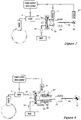
- Fig. 1 shows a combustion system comprising a combustion engine 1, typically being a Diesel engine, a tank 2 holding a liquid solution of urea (also known under the trade name AdBlue) and a catalytic system 3.
- the exhaust of the engine 1 is connected to the catalytic system 3 by an exhaust pipe 4.
- the combustion system further comprises a nozzle 5 connected to a fluid transfer unit 6 (broadly termed "a through flow device") which is connected to the tank 2.
- the fluid transfer unit 6 receives the liquid solution of urea and provides it to the nozzle 5 in amounts meeting the demand for urea in the catalytic system at least to some extent.
- Fig. 2 shows schematically the architecture of the fluid transfer unit (6 in fig. 1 ) for introducing urea into the exhaust system of a combustion engine. Same numerals as used for designating elements in fig. 1 are used for designating similar elements in fig. 2 .
- the system architecture as shown in fig. 2 comprises a dosing pump 7 connected at its inlet to the tank 2 for pumping and dosing urea to a buffer 8.
- the buffer 8 is via a shut-off valve 9 connected to the nozzle 5.
- the dosing pump 7 of the embodiment according to fig. 2 is a pump pressurising fluid and generating a controllable variable flow rate and thereby a controlled delivery. This means that the actual flow rate can be controlled very precisely.
- the accuracy of the flow rate delivered by the dosing pump 7 is typically lower than +/- 1 % of the full-scale delivery when the delivery is larger than 10 % of the full-scale delivery. Below that amount, the accuracy is lower than +/- 10% of the reading value being the amount the dosing pump 7 is set to provide.
- the dosing pump is controlled by a motor control unit 11 which receives input representing the actual demand for urea, and the motor control unit 11 sets the dosing pump to pump this actual demand.
- the motor control unit 11 and the shut-off valve control unit 10 is shown as different elements of the system. However, those two units may be assembled into a single unit. Basically, the two units serves the following two purposes:
- All parts of the system may be integrated into a single unit.
- the tank and the nozzle are typically not integrated parts of the system, whereby the system may be placed at an appropriated place of e.g. a truck.
- the nozzle 5 is a nozzle that provides atomized fluid once the pressure of the fluid fed to the nozzle 5 is above a threshold P max . Above that threshold, the amount of fluid being atomized equals the amount of fluid provided by the dosing pump 7. However, below the threshold, the nozzle 5 will not be able to atomize all fluid, as the amount of fluid streaming towards the nozzle is too small to build up a pressure above the threshold. When this occurs, the shut-off valve 9 controls whether fluid is fed to the nozzle 5 or not in the manner disclosed below. In typical applications, the amount of fluid to be atomized ranges from e.g. 0.1% to 100% of the maximum amount of fluid to be atomized and atomization of a continuously flowing fluid over such an interval is typically not considered feasible.
- the shut-off valve 9 is a valve that opens when the pressure in the fluid pumped towards it is above a maximum pressure limit P max ( fig. 3 ) and closes once the pressure is below a minimum limit P min .
- P max is typically 5 % higher than P min and P min is the level at which it can be assured that the fluid fed to the nozzle 5 is atomized by the nozzle 5. Below that pressure level, the nozzle 5 may be able to atomize but it can in general not be assured, as atomization requires a pressure difference across the nozzle of a certain level.
- the shut-off valve closes and stays closed until the dosing pump 7 has pumped sufficient fluid to build up a pressure above P max .
- P max the shut-off valve 9 opens and the fluid streams through the nozzle 5.
- the amount being atomised is higher than what is delivered by the dosing pump 7 so the pressure drops until P min where the valve closes and a pressure build up is initiated again.
- the amount of fluid atomised in time average equals the amount of fluid delivered by the dosing pump 7.
- FIG. 3 this figure shows three different atomisation regimes, large flow ( fig.3a ), medium flow ( fig. 3b ), and small flow ( fig. 3c ).
- the instantaneous pressure in the flow measured at the inlet of the shut-off valve 9 is after a while constantly above the limits of P max and P min . If the demand decreases, the amount of fluid pumped by the dosing pump 7 will decrease resulting in a pressure decrease. The pressure can be decreased until P min and stay constant at a level above P min as long as the decrease occurs from a level being above P max . If the demand is very large or e.g. the nozzle 5 is clogged, the pressure may increase until it reaches a safety limit P high at which the dosing pump 7 stops pumping fluid but the shut-off valve 9 stays open.
- the atomisation enters into the regime disclosed schematically in fig. 3b .
- the pressure measured at the inlet of the shut-off valve 9 is at one instance lower than P max and the shut-off valve 9 is accordingly closed; it is here assumed that the shut-off has not been opened, i.e. the state is reached from a level where the shut-off valve has been closed.
- the shut-off valve 9 is closed and the dosing pump 7 is still pumping, fluid will be accumulated in the buffer 8 and as the buffer 8 is a resilient member, accumulation of fluid therein will take place resulting in that the pressure at the inlet of the shut-off valve 9 will increase.
- a minimum flow regime is schematically shown in fig. 3c .
- the pressure does not reach the limit of P max being the pressure at which the shut-off valve 9 opens for fluid flowing to the nozzle 5.
- the shut-off valve 9 is forced open at intervals, typically being at regular intervals.
- the time where the shut-off valve 9 is closed is in fig. 3c indicated by "set time interval” and the length thereof is pre-selected as the maximum allowable time for no delivery.
- the time length of a pulse is in fig. 3c indicated as "pulse time”.
- a cycle in this minimum flow regime comprises two phases. The first phase begins (for instance) when the pressure is at P min and the shut-off valve 9 closes.
- the shut-off valve 9 is forced open and as the fluid flows towards and out of the nozzle 5, the pressure decreases until the pressure reaches P min .
- the time intervals between two pulses can be kept lower than if one should await a pressure build-up to P max and as the intervals between two pulses can be kept low, one may be able to provide e.g. an even delivery of urea in the streaming exhaust gasses.
- the length of the time interval between two pulses is typically pre-selected and is typically found by performing experiments.
- P max and P min are defined by selecting P max and P min in combination with selecting the length of "set time interval". Actual values of these parameters are selected in accordance with an actual nozzle configuration.
- P max is selected to be 8,4 bar
- P min is selected to be 8,1 bar
- "set time interval" is selected to be one or a few seconds.
- the minimum amount of fluid being fed to the nozzle 5 is around 0.010 l/h
- the flexibility of the buffer 8 is 160 mm 3 /bar.
- the opening and closing of the shut-off valve 9 is electromagnetically controlled from a valve controlling unit 10 as shown in fig. 2 by the connection 12.
- the connection 12 transfers an electrical signal to the shut-off valve 9.
- the buffer 8 may provide the effect that the frequency at which the shut-off valve 9 operates can be decreased compared to a system where no buffer 8 is incorporated in the system.
- the pressure within the fluid transfer system increases.
- the fluid is considered to be incompressible and once the shut-off valve 9 is opened, the pressure in the fluid transfer system will, if no buffer 8 is incorporated and the dosing pump 7 is not pumping, drop to the level outside the nozzle 5 almost instantaneously.
- the buffer 8 is a resilient member, the contraction of the buffer's 8 volume will maintain the pressure within the fluid transfer higher than P min for a much longer period, thus the time between two consecutive openings of shut-off valve 9 can be of sufficient length to secure a sufficient lifetime of the shut-off valve 9.
- the buffer will make it possible to use a much slower (and thus cheaper) valve. If the buffer is too big, it can introduce an unacceptable dynamic error.
- a pressure sensor 13 measures the pressure within the buffer 8. The measured pressure is used for controlling the state of the shut-off valve 9 (open or close) and the pressure measured is used as if it was the pressure measured at the inlet of the valve. The measured pressure is signalled to a controlling unit 10 via the connection 14.
- connection 15 from the shut-off valve 9 to the nozzle 5 is sufficiently stiff to assure that once the shut-off valve 9 is opened, the pressure increase in the connection 15 will in a substantial manner not result in any deformation of the connection 15. If, on the other hand, the connection was not substantially stiff, opening of the shut-off valve 9 would cause the connection 15 to expand resulting in that the amount of urea streaming out of the outlet of the shut-off valve 9 would not substantially instantaneously equal the amount streaming out of the nozzle 5 which normally would be considered as introducing errors into the fluid transfer system.
- the connection 15 is typically a line made of stainless steel.
- connection 15 helps also to minimize droplets from being formed at the outlet of the nozzle as the shutting-off of the shut-off valve if done sufficiently fast will result in that no fluid will stream out of the nozzle. If, on the other hand, the connection 15 was not sufficiently stiff, the connection would contract once the shut-off valve is shut-off resulting in fluid being forced out of the nozzle and a droplet formed at outlet of the nozzle. Such droplet may crystallise and result in clogging of the nozzle. It is noted that such stiff connection is applied to all the embodiments of the invention.
- Fig. 4 shows an example not forming part of the invention in a conceptual manner.
- the system of fig. 4 is supplied with liquid at a constant pressure (within limits regardless of flow) from a pump 17 or alternatively from a pressurised tank 18.
- Measuring unit 19 provides information on the delivered amount measures the actual amount delivered.
- a motor/valve control unit 20 operates the shut-off valve 9 typically and preferably pulsating in a PWM (pulse width modulated) manner in accordance with the actual need for urea in relation to system specific parameters such as nozzle constant, characteristics of the valve, pressure of the fluid before the nozzle etc. In this way a change in flow as demanded from the motor conditions will very quickly be provided through the nozzle 5 thus giving a very little dynamic error. Signals via the connection 21 from measuring unit 19 will provide information for changing the PWM of shut-off valve 9 in order to minimize the accumulative error.
- PWM pulse width modulated
- Fig. 5 shows a variant of the system in fig. 4 where the measuring unit and pump are combined into a single unit 22.
- Fig. 6 shows an example of the system corresponding to fig. 4 .
- the transfer system comprises a tank 18 containing pressurised fluid.
- the tank 2 may contain fluid at ambient pressure and a pump 17 may provide pressurisation.
- a valve 23 is provided having its outlet connected to a measuring unit.
- the measuring unit comprises a piston 24 attached to and acting on a membrane 25.
- the movement of the piston 24 and thus the membrane 25 is limited relatively to the housing to which it is attached.
- the piston 24 is biased towards the membrane 25 by a spring 26.
- a shut-off valve 9 is provided which in dosing conditions acts as explained above with respect to fig. 4 .
- shut-off valve 9 In non-dosing conditions (when piston 24 is moved backwards and liquid is streaming into the measuring unit) the shut-off valve 9 must be closed.
- the valves 9 and 23 are both magnetic valves. Once the shut-off valve 9 is closed and the valve 23 is opened and the force from the fluid flowing through valve 23 and acting on the membrane is larger than the force on the piston 24 coming from the spring 26, the spring 26 will be compressed and the piston 24 will be displaced until stopped by the facing of the house. This end position is detected by the sensor 27 which through the connection 21 will signal to the control unit which in turn closes the valve 23 and start operating shut-off valve 9. During this operation, the biasing force from the spring 26 will displace the piston 24 in opposite direction thereby pressing fluid being accumulated in the measuring unit towards the shut-off valve 9.
- the fluid transfer system of fig. 6 is used in the following manner. Initially, the shut-off valve 9 is closed and the valve 23 is opened. Once the valve 23 is opened, the membrane 25 and the piston 24 move against the biasing force from the spring 26. The valve 23 stays open until the displacement sensor 27 detects that the piston 24 has reached its bottom position where no further compression of the spring 26 occurs. The sensor sends a signal to the control unit 20 once the piston has reached its bottom position. Thereafter the valve 23 is closed and the shut-off valve 9 is opened and operated in PWM mode until the piston has reached its top position. The sensor 27 signals this to the control unit 20.
- the delivered amount can be monitored by logging the signal representing the upper or lower most position of the piston 24. Once the piston 24 reaches its uppermost position, the shut-off valve 9 is closed, the valve 23 is opened and the cycle is repeated.
- Fig. 7 shows an example of the system corresponding to fig. 5 .
- a combined pump/measuring unit performs the pressurisation of the fluid and gives information to the control unit 20 about the amount delivered.
- the transfer system comprising a tank 2 connected to the pumping/measuring unit 22 via a valve 23.
- the valve 23 is a one-way valve and a further one-way valve 28 is arranged in the outlet of the pump/measuring unit.
- the pumping in this example also comprises a piston 24, a membrane 25 and a spring 26. The assembly of the piston 24, the membrane 25 and the spring 26 is slidably attached to a sub-piston 29.
- the sub-piston 29 is connected via a connecting rod 30 to a crank 31 so that the rotation of the crank 31 results in a reciprocating displacement of the sub-piston 29.
- the piston 24 will tend to follow this reciprocating displacement of the sub-piston 29.
- the piston 24 is slidable arranged in the sub-piston 29 and biased by the spring 26 the displacement of the piston 24 will differ from the displacement of the sub-piston 29.
- the transfer system is equipped with a sensor 27 sensing the end positions in the relative movement between piston 24 and sub-piston 29.
- a further sensor 32 is arranged for sensing the upper dead position of the crank 31.
- the nozzle When the spring 26 has been maximally compressed and the crank 31 is stopped in upper dead position (signalled by the sensor 32 to the control unit 20), the nozzle can atomize urea in PWM mode as previously described and the spring 26 will start to expand. Such expansion of the spring 26 will result in that fluid may still be pressurised and delivered even though the crank 31 is not rotating. In fact it may be essential for the function of the system that the shut-off valve 9 only is operated when the crank 31 and thus the sub-piston is not moving.
- Fig. 8 shows another example of the system corresponding to fig. 5 .
- This example has many similarities with the example shown in fig. 7 and same numerals are used for similar elements.
- the movement of the piston 24 and thus the membrane 25 is limited relatively to the housing and not relatively to the sub-piston 29 whereby the precision can be improved and the detection of end positions can be simplified.
- the sub-piston 29 engages with the piston 24 via a preloaded spring 33. In the top dead position there is a clearance between spring 33 and sub-piston 29 and in the lower dead position the spring 33 can be slightly further compressed. This means that the movement of the crank mechanism is uncritical concerning precision. Apart from this, the function is as described in connection with figure 7 .
- Fig. 9 shows another example of the system corresponding to fig. 5 .
- This example comprises a pump/measuring unit connected at the inlet to a tank via a one-way valve 23, and at the outlet of the pumping/measuring unit a one-way valve 28 is arranged.
- the two one-way valves 23 and 28 play the same role as the two one-way valves in a normal pump.
- the pump/measuring unit comprises a piston 24 and a membrane 25 similar to the piston and membrane of the above discussed examples.
- the piston 24 in this embodiment is directly connected to a crank 31 via a connecting rod 30.
- the pump is typically controlled to maintain a substantially constant pressure at the shut-off valve 9.
- the shut-off valve 9 is typically opened and closed in a pulsating (PWM) manner based on the actual need for urea. Due to the highly defined geometry, each revolution of the crank represents a well-defined and known volume delivered, and a sensor 32 may detect the amount pumped by picking up a signal for each revolution or a known fraction of a revolution. This detection is uncritical as an error is not accumulating. The signals will via the connection 34 provide information for changing the PWM of shut-off valve 9 in order to minimize the accumulative error.
- PWM pulsating
- the shut-off valve 9 can be operated without interruption in the earlier described manner (PWM).
- the pump may have two membranes operating in opposite phases, one membrane having a suction stroke while the other is pumping.
- shut-off valve 9 arranged before the nozzle.
- the shut-off valve may be dispensed with, it is preferably applied in order to control the flow of urea to the nozzle; in some embodiments and examples the shut-off valve is in combination with a buffer used to secure sufficient pressure of the fluid and in alternative examples not forming part of the invention used to control the amount of fluid delivered to the nozzle. A combination thereof is, of course, also possible.
- delivery of urea may mainly be performed in four different manners:
- Fig. 10 shows graphically an example of a strategy for delivery of urea according to examples not forming part of the present invention.
- the strategy is based on PWM (pulse width modulation).
- PWM and PIM pulse interval modulation
- PIM pulse interval modulation
- PWM provides the possibility to choose a suitable pulse interval while taking into account the dynamics (typically the buffer effect) of the catalytic system.
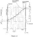
- the strategy shown in fig. 10 is based on comparing accumulated delivery with accumulated demand at certain points in time (when the measuring pump or the measuring unit sends information about delivered amounts to the motor/valve control unit). Based on this information, the algorithm for controlling the width of the pulses is changed in order to maintain a good accuracy.
- C0, C1, C2, C3, C4 and C5 represent points in time where accumulated delivery is compared with accumulated demand.
- the immediate demand (ml/s, labelled demand in fig. 10 ) is prescribed by a controlling unit, typically a motor controlling unit.
- the accumulated demand (ml), delivered amount (ml/s, labelled delivery (pulses)) and accumulated delivery (ml) are indicated in fig. 10 .
- Accumulated values may preferably be determined by integration. For illustration, the accumulated curves are shown as continuous curves but in praxis, the control unit will compare values at an interval (C1, C2,.. etc.) and calculate a single deviation value for use in the next interval (as will be seen in fig. 11 ).
- the administrating algorithm determining activation of the shut-off valve may comprise a number of elements, such as deviations in the accumulated delivery from accumulated demand, error in accumulated delivered amount between two feedback times, the rate of change at which such error changes etc.
- delivery is made with a constant pulse within each interval if the demand is constant.
- the accumulated delivery is compared to the accumulated demand and it is found that the delivery has been too high. Consequently, the pulse width is decreased at C1 and kept constant from C1 to C2.
- the accumulated demand is again compared to the accumulated delivery and it is found that the accumulated delivery still is higher than the accumulated demand although the accumulated delivery is approaching the accumulated demand. Consequently, the pulse width is decreased further.
- the demand for delivery is increased and as the accumulated demand is higher than the accumulated delivery at C3, the pulse width is consequently increased in order to increase the delivery.
- the increase is not sufficient to meet the demand and at C4 the pulse width is again increased.
- Pulse width is determined by the motor/valve control unit as a function of system parameters (nozzle constant, pressure of the fluid at the shut-up valve, viscosity of the fluid, valve characteristic etc.), the need for delivery flow at the start of a pulse and the time distance between pulses.
- the value will be approximately Fdemand/Fmax ⁇ Tp, where Fdemand denotes the need of delivery flow at the start of a pulse, Fmax stands for the flow with an open shut-up valve, and Tp is the time between two subsequent pulses.
- the correcting signal is sent to the motor/valve control unit and the accumulated demand is compared to V(control).
- the surplus (V(control)-V(Cn-1 - Cn)) and the known accumulated error at Cn ( ⁇ Cn) determines the accumulated error at time Cn+1.
- figs. 12 and 13 show a measuring unit 19 shaped as a corbie-stepped piston device.
- figs. 12 and 13 are applicable in connection with other strategies.
- the measuring unit 19 comprises a cylinder 39 in which a corbie-stepped piston 38 is slideable arranged.
- the corbie-stepped shape of the piston 38 is provided by the piston part 38c whereby the area 38a is larger than the area 38b as shown in the figure.
- the measuring device 19 receives fluid through valve 36.
- the fluid is pressurised to a pressure P and is received from a pressurised reservoir or a pump.
- the outlet of valve 36 connected to the larger displacement volume 40a of cylinder 39, and connected to the smaller displacement volume 40b of the cylinder 39 via a valve 37.
- the connection between the valve 37 and the smaller displacement volume 40b also comprises a discharge 41 in the configuration shown in fig. 12 .
- a displacement volume 42 is provided above the end of the piston part 38c opposite the end connected to the piston 38 .
- This displacement volume 42 receives fluid at the same or substantially same pressure P as fed to the valve 36.
- the fluid supplied to valve 36 and displacement volume 42 comes from the same source.
- Fig. 12 shows two modes of the measuring device.
- valve 36 is open and valve 37 is closed whereby fluid at pressure P streams towards the larger displacement volume 40a.
- the piston 38 will be displaced to the right with reference to fig. 12 .
- the right-going movement results in that fluid present in displacement volume 40b is pressed out through the discharge 41. This action continues until the piston 38 reaches its right-most position at which position valve 36 is closed and valve 37 is opened; this situation is disclosed in lower part of fig. 12 .
- valve 36 When valve 36 is closed and valve 37 is open, the pressure in displacement volume 42 will push the piston 38 to the left with reference to fig. 12 . Fluid present in displacement volume 40a will flow out, through the valve 37 and into the displacement volume 40b as well as out through the discharge 41. This left-going action continues until the piston 38 reaches its left-most position, when the states of the valves 36 and 37 are both changed and the cycle repeats.
- the example of fig. 12 has among other advantages that the delivery is present except at the left-most and right-most positions of the piston and that the pressure of the fluid delivered to the discharge 41 is well defined. Furthermore, a strong geometrical relationship is present between the amount of fluid delivered through discharge 41 and the movement of the piston part 38c.
- the size of the areas 38a and 38b may be selected so that the same amount is delivered to the discharge irrespective of the way the piston 38 moves. This may be achieved when the size of area 38a is twice the size of area 38b. Furthermore, the sizes of the displacement volumes have the following ratio 2:1:1 (40a:40b:42). Examples like the one shown in fig. 12 has the further advantages that the direction change of the piston 38 can be performed very quickly and thereby only little interruption in fluid delivery is present (the directional change is typically governed by the speed at which the state of the valves can be changed). In other examples where a suction stroke is present, the interruption is comparably larger.
- valves 36 and 37 By arranging the valves 36 and 37 as indicated in fig. 12 , redirection valves are not needed and the relatively simpler shut-off valves may be applied.
- Fig. 13 shows an example similar to the example of fig. 12 .
- Features of the example shown in fig. 13 which are similar to features shown in fig. 12 have been labelled with the same numerals.
- the upper part of fig. 12 shows a situation where the piston 38 moves to the right, and the lower part shows a situation where the piston moves to the left.
- sealing membranes 43a and 43b are provided between the piston 38 and the displacement volume 40a and between the piston part 38c and the displacement volume 42.
- the presence of the sealing membranes 43a and 43b provides a seal hindering fluid from flowing between the volumes 40a and 40b past the edge of the piston 38.
Landscapes
- Engineering & Computer Science (AREA)
- Chemical & Material Sciences (AREA)
- Chemical Kinetics & Catalysis (AREA)
- Combustion & Propulsion (AREA)
- Mechanical Engineering (AREA)
- General Engineering & Computer Science (AREA)
- Health & Medical Sciences (AREA)
- Toxicology (AREA)
- Exhaust Gas After Treatment (AREA)
- Control Of Positive-Displacement Pumps (AREA)
- Feeding, Discharge, Calcimining, Fusing, And Gas-Generation Devices (AREA)
Description
- The present invention relates to a fluid transfer system and method for transferring urea or urea derivatives from a reservoir and to a nozzle. The present invention relates in particular to transferring urea or urea derivatives in highly accurate metered amounts from a reservoir to a nozzle arranged within an exhaust system of a combustion engine or combustion engines.
- It has been found that introduction of urea into the exhaust gasses streaming from a combustion engine and into a catalytic system may dramatically increase the efficiency of the catalytic element's capability to convert NOx gasses. While urea in itself is relatively harmless to the environment and the amounts introduced into the combustion system thereby can be overdosed, such wasting of urea is often undesirable as the technology is often applied to moving vehicles and such waste would require larger storage capacities than what is actually needed if urea is dosed correctly.
- A need for introducing the required amount of urea into the exhaust gasses only is therefore present. Furthermore, urea is most efficiently introduced into the exhaust gasses as a spray of droplets which typically requires that the urea is pressurised and fed to a nozzle.
US 6 209 315 B1 ,US 2005/247048 A1 andUS 2002/088220 A1 disclose a urea dosing system. - It is an object of the present invention to provide a fluid transfer system and method providing an efficient controllable delivery of urea or urea derivatives from a reservoir to a nozzle.
- Thus, in a first aspect the present invention preferably relates to a fluid transfer system for transferring urea or urea derivatives from a reservoir to a nozzle, the fluid transfer system comprising
- a through flow device adapted to receive the urea or urea derivatives from the reservoir and transfer the urea or urea derivatives through the system and/or measuring the amount of the urea or urea derivatives being transferred from the reservoir to the nozzle,
- a controllable shut-off valve arranged upstream of the receiving device and downstream of the through flow device, and
- a controlling unit controlling at least the state of the shut-off valve,
- wherein the through flow device comprises a dosing pump,
- wherein the nozzle is adapted to atomize the transferred urea or urea derivatives without mixing it with pressurized air,
- wherein the controlling unit is adapted to control the state of the shut-off valve, so that the pressure of the urea or urea derivatives being fed to the receiving device is above a first pre-selected pressure limit (Pmin) being a level at which it can be assured that the urea or urea derivatives fed to the nozzle is atomized by the nozzle, wherein the controlling unit turns the shut-off valve into its open state when the pressure upstream of the shut-off valve is above a second pre-selected pressure limit (Pmax),
- wherein the controlling unit turns the shut-off valve into its closed state when the pressure upstream of the shut-off valve is decreased to the first pre-selected pressure limit (Pmin) so that a pressure build up is initiated again, and
- wherein the system further comprises a fluid connection extending from the shut-off valve to the nozzle, the fluid connection is a line made of stainless steel and being stiff so as to avoid expansion of the fluid connection which would cause uncontrollable flow through the connection due to contraction of the connection when the shut-off valve is closed.
- The through flow device may further comprise a pump.
- In the present context, a number of terms are used. Even though these are used in their ordinary meaning, a further exemplary explanation is given on some of the terms.
- Dynamical error in delivered amount: A dynamical error occurs when the demand for delivered fluid varies with time and is caused by a delay between when the amount is delivered and when it should have been delivered. The delay is typically due to elasticity in the fluid delivery system, delay in prosecution of controlling and/or sensing signal and/or the like. A dynamical error may be defined as the maximum value of the difference between the desired amount and the actual delivered amount during a pre-defined time. The dynamical error is not accumulated.
- Accumulative error in delivered amount: An accumulative error in delivered amount is typically defined as an error which is not balanced over time.
- Dosing pump: A unit delivering a precise amount of liquid controlled by an electrical signal from a control unit and which is capable of doing so against a high pressure.
- Pump (p pump): A unit delivering an uncontrolled flow of liquid against a high pressure or a unit capable of maintaining a high pressure.
- Measuring unit: A unit giving information (most often as electrical signals) about flow of liquid without influencing flow or pressure.
- Measuring pump: A combination of a pump and the measuring unit.
- Through flow device: A device adapted to receive fluid from a reservoir and transfer the fluid and/or measuring the amount of fluid being transferred from the reservoir and to a receiving device.
- Demand: The amount to be delivered. Demand may be the immediate demand expressed in e.g. litre per hour [l/h] or demand accumulated over an interval expressed in e.g. hour [h].
- Delivery: The amount to be delivered. Delivery may be the immediate delivery expressed in e.g. litre per hour [l/h] or delivery accumulated over an interval expressed in e.g. hour [h].
- The invention involves preferably at least one way of dosing fluid (further ways are explained later on) including the use of a dosing pump: The dosing pump provides very accurately the amount demanded and the dosing pump is accordingly controlled to provide a delivery corresponding to a demand. The pressurisation of the fluid is preferably obtained by a combination of a fluid buffer arranged downstream of the dosing pump and a shut-off valve arranged downstream of the buffer.
- Examples of alternative ways that do not form part of the invention are based on using a measuring unit. In such examples, the fluid is pressurised in some manner; typically the fluid is stored pressurised in a reservoir or pressurised by a pump. A demand is typically expressed at regular intervals and the total amount to be delivered in a given interval is typically estimated to equal the demand (in l/h) at the beginning of the interval multiplied by the length (in hour) of the interval. Use of a dosing unit may be summarised in the following manner:
- a: The delivery of fluid can be estimated from a functional relationship giving delivered amount per hour multiplied by the opening time of the shut-off valve. From such a relationship the time in a given interval the valve must be open for meeting a demand. During delivery, the actual delivered amount is measured by the measuring unit, and if discrepancy is found between the estimated delivered amount and the actual delivered amount, a feedback is made to the algorithm determining the opening time of the shut-off valve to take into account the discrepancy.
- b: The actual delivery is measured during delivery. Once the demand in a given interval has been met, the shut-off valve is closed.
- It should be noted that the above summaries are examples only, and that variations of these two occur and they are therefore not intended to be construed in a narrowing way. For instance, in some examples, the measuring unit and pressurisation unit are integrated into each other.
- As it will appear in the following, a pump will in some embodiment pressurise fluid received from the tank. However, in some other embodiment the system receives pressurised fluid from the tank and in such embodiment the pump will not be necessary.
- The present invention relates in a second aspect preferably to a method of transferring urea or urea derivatives from a reservoir (2) to a nozzle (5), by use of a fluid transfer system comprising
- a through flow device (6) adapted to receive the urea or urea derivatives from the reservoir (2) and transfer the urea or urea derivatives through the system and/or measuring the amount of urea or urea derivatives being transferred from the reservoir to the nozzle,
- a controllable shut-off valve (9) arranged upstream of the nozzle and downstream of the through flow device (6),
- a controlling unit controlling at least the state of the shut-off valve (9),
- wherein the through flow device comprises a dosing pump (7), and
- wherein the nozzle is adapted to atomize the transferred urea or urea derivatives without mixing it with pressurized air,
- the method comprising controlling the state of the state of the shut-off valve
- so that the pressure of the urea or urea derivatives being fed to the nozzle is above a first pre-selected pressure limit (Pmin) being a level at which it can be assured that the urea or urea derivatives fed to the nozzle is atomized by the nozzle, wherein the controlling of the state of the shut-off valve comprises turning the shut-off valve (9) into its open state when the pressure upstream of the shut-off valve (9) is above a second pre-selected pressure limit (Pmax),
- wherein the controlling of the state of the shut-off valve comprises turning the shut-off valve (9) into its closed state when the pressure upstream of the shut-off valve (9) is decreased to the first pre-selected pressure limit (Pmin) so that a pressure build up is initiated again, and
- wherein the system further comprises a fluid connection (15) extending from the shut-off valve (9) to the nozzle, the fluid connection is a line made of stainless steel and being stiff so as to avoid expansion of the fluid connection (15) which would cause uncontrollable flow through the connection due to contraction of the connection (15) when the shut-off valve (9) is closed.
- Also in this connection the through flow device may further comprise a pump.
- The controlling of the shut-off valve to meet a given demand is preferably performed based on direct control of the shut-off valve based on the system characteristic for obtaining a minimum dynamic error and a correction signal from the measuring unit to modify an algorithm for controlling the valve in order to avoid accumulative error.
- The present invention and in particular preferred embodiments thereof will now be described in details with reference to the accompanying figures, wherein
-
Fig. 1 shows schematically a combustion system according to a preferred embodiment of the present invention, -
Fig. 2 shows schematically a first embodiment of a fluid transfer system unit according to the present invention, -
Fig. 3 shows schematically three different flow regimes obtainable by the fluid transfer systems according to the present invention, -
Fig. 4 shows an example that does not form part of the invention in a conceptual manner, -
Fig. 5 shows a variant of the system infig. 4 where the pressurising and measuring function is combined, -
Fig. 6 shows schematically an example of a fluid transfer system corresponding tofig. 4 , -
Fig. 7 shows schematically an example of a fluid transfer system corresponding tofig. 5 , -
Fig. 8 shows schematically another example of a fluid transfer system corresponding tofig. 5 , -
Fig. 9 shows schematically a third example of a fluid transfer system corresponding tofig. 5 , -
Fig. 10 shows graphically an example on a strategy for delivery of urea not forming part of the present invention, -
Fig. 11 shows graphically details on a strategy for delivery of urea not forming part of the present invention,
and -
Figs. 12 and13 each shows schematically examples of measuring units not forming part of the present invention. -
Fig. 1 shows a combustion system comprising acombustion engine 1, typically being a Diesel engine, atank 2 holding a liquid solution of urea (also known under the trade name AdBlue) and acatalytic system 3. The exhaust of theengine 1 is connected to thecatalytic system 3 by anexhaust pipe 4. The combustion system further comprises anozzle 5 connected to a fluid transfer unit 6 (broadly termed "a through flow device") which is connected to thetank 2. Thefluid transfer unit 6 receives the liquid solution of urea and provides it to thenozzle 5 in amounts meeting the demand for urea in the catalytic system at least to some extent. -
Fig. 2 shows schematically the architecture of the fluid transfer unit (6 infig. 1 ) for introducing urea into the exhaust system of a combustion engine. Same numerals as used for designating elements infig. 1 are used for designating similar elements infig. 2 . The system architecture as shown infig. 2 comprises a dosing pump 7 connected at its inlet to thetank 2 for pumping and dosing urea to abuffer 8. Thebuffer 8 is via a shut-offvalve 9 connected to thenozzle 5. - The dosing pump 7 of the embodiment according to
fig. 2 is a pump pressurising fluid and generating a controllable variable flow rate and thereby a controlled delivery. This means that the actual flow rate can be controlled very precisely. The accuracy of the flow rate delivered by the dosing pump 7 is typically lower than +/- 1 % of the full-scale delivery when the delivery is larger than 10 % of the full-scale delivery. Below that amount, the accuracy is lower than +/- 10% of the reading value being the amount the dosing pump 7 is set to provide. The dosing pump is controlled by amotor control unit 11 which receives input representing the actual demand for urea, and themotor control unit 11 sets the dosing pump to pump this actual demand. - In order to render the different functions of the system of
fig. 2 more visible, themotor control unit 11 and the shut-offvalve control unit 10 is shown as different elements of the system. However, those two units may be assembled into a single unit. Basically, the two units serves the following two purposes: -
Motor control unit 11, which on the basis of parameters defining the state of the engine, e.g. load and rpm, defines the actual demand for urea and signals the demand to the dosing pump 7. The dosing pump 7 may be an ordinary dosing pump measuring an amount of urea meeting the actual demand for urea and pressurising the metered amount of urea to a pressure level being sufficient for the nozzle to provide atomisation of the metered urea. - Shut-off
valve control unit 10 controlling the state of the shut-off valve i.e. changes the shut-off valve state from open to close or vice versa on the basis of the pressure of the fluid measured in thebuffer 8 and at the same time provides a desired distribution of the periods in which the shut-off valve is open. - All parts of the system may be integrated into a single unit. However, the tank and the nozzle are typically not integrated parts of the system, whereby the system may be placed at an appropriated place of e.g. a truck.
- The
nozzle 5 is a nozzle that provides atomized fluid once the pressure of the fluid fed to thenozzle 5 is above a threshold Pmax. Above that threshold, the amount of fluid being atomized equals the amount of fluid provided by the dosing pump 7. However, below the threshold, thenozzle 5 will not be able to atomize all fluid, as the amount of fluid streaming towards the nozzle is too small to build up a pressure above the threshold. When this occurs, the shut-offvalve 9 controls whether fluid is fed to thenozzle 5 or not in the manner disclosed below. In typical applications, the amount of fluid to be atomized ranges from e.g. 0.1% to 100% of the maximum amount of fluid to be atomized and atomization of a continuously flowing fluid over such an interval is typically not considered feasible. - The shut-off
valve 9 is a valve that opens when the pressure in the fluid pumped towards it is above a maximum pressure limit Pmax (fig. 3 ) and closes once the pressure is below a minimum limit Pmin. Pmax is typically 5 % higher than Pmin and Pmin is the level at which it can be assured that the fluid fed to thenozzle 5 is atomized by thenozzle 5. Below that pressure level, thenozzle 5 may be able to atomize but it can in general not be assured, as atomization requires a pressure difference across the nozzle of a certain level. Thus, when the flow rate from the dosing pump 7 is too small to provide a pressure above Pmin, the shut-off valve closes and stays closed until the dosing pump 7 has pumped sufficient fluid to build up a pressure above Pmax. Once the pressure exceeds Pmax the shut-offvalve 9 opens and the fluid streams through thenozzle 5. During this streaming, the amount being atomised is higher than what is delivered by the dosing pump 7 so the pressure drops until Pmin where the valve closes and a pressure build up is initiated again. By this procedure, the amount of fluid atomised in time average equals the amount of fluid delivered by the dosing pump 7. - Referring to
fig. 3 , this figure shows three different atomisation regimes, large flow (fig.3a ), medium flow (fig. 3b ), and small flow (fig. 3c ). As shown infig. 3a the instantaneous pressure in the flow measured at the inlet of the shut-offvalve 9 is after a while constantly above the limits of Pmax and Pmin. If the demand decreases, the amount of fluid pumped by the dosing pump 7 will decrease resulting in a pressure decrease. The pressure can be decreased until Pmin and stay constant at a level above Pmin as long as the decrease occurs from a level being above Pmax. If the demand is very large or e.g. thenozzle 5 is clogged, the pressure may increase until it reaches a safety limit Phigh at which the dosing pump 7 stops pumping fluid but the shut-offvalve 9 stays open. - When the demand for atomized fluid is at medium flow, the atomisation enters into the regime disclosed schematically in
fig. 3b . In this regime, the pressure measured at the inlet of the shut-offvalve 9 is at one instance lower than Pmax and the shut-offvalve 9 is accordingly closed; it is here assumed that the shut-off has not been opened, i.e. the state is reached from a level where the shut-off valve has been closed. As the shut-offvalve 9 is closed and the dosing pump 7 is still pumping, fluid will be accumulated in thebuffer 8 and as thebuffer 8 is a resilient member, accumulation of fluid therein will take place resulting in that the pressure at the inlet of the shut-offvalve 9 will increase. This pressure increase will continue as long as the dosing pump 7 is pumping and the shut-offvalve 9 stays closed. Once the pressure reaches Pmax the shut-offvalve 9 will open. Opening of the shut-offvalve 9 will result in that fluid is streaming towards thenozzle 5. The fluid streaming towards the shut-offvalve 9 is a combination of fluid being pumped by the dosing pump 7 and the change in volume of thebuffer 8. The effect of the decreasing buffer volume is indicated infig. 3b with the dotted line denoted "pressure drop without inflow". The amount of fluid pumped by the dosing pump 7 is, in the regime shown infig. 3b , insufficient to keep the pressure above Pmin, and once the pressure has dropped to Pmin the shut-offvalve 9 closes where after accumulation of fluid in thebuffer 8 begins, again, with an increasing pressure as a result. This cycle continues as long as the demand for fluid is not changed. As it appears, the flow through thenozzle 5 in this regime will be pulsed and the time length of each pulse is the time from opening of the shut-off valve at Pmax until closing of the shut-off valve at Pmin - A minimum flow regime is schematically shown in
fig. 3c . As shown infig. 3c , the pressure does not reach the limit of Pmax being the pressure at which the shut-offvalve 9 opens for fluid flowing to thenozzle 5. In order to atomize fluid, the shut-offvalve 9 is forced open at intervals, typically being at regular intervals. The time where the shut-offvalve 9 is closed is infig. 3c indicated by "set time interval" and the length thereof is pre-selected as the maximum allowable time for no delivery. The time length of a pulse is infig. 3c indicated as "pulse time". A cycle in this minimum flow regime comprises two phases. The first phase begins (for instance) when the pressure is at Pmin and the shut-offvalve 9 closes. As the dosing pump 7 continues pumping, the pressure increases as disclosed above in the medium flow regime. When the set time interval has passed, the shut-offvalve 9 is forced open and as the fluid flows towards and out of thenozzle 5, the pressure decreases until the pressure reaches Pmin. By utilising this forced opening of the shut-off valve, the time intervals between two pulses can be kept lower than if one should await a pressure build-up to Pmax and as the intervals between two pulses can be kept low, one may be able to provide e.g. an even delivery of urea in the streaming exhaust gasses. The length of the time interval between two pulses is typically pre-selected and is typically found by performing experiments. - The various flow regimes, high, medium and minimum, are defined by selecting Pmax and Pmin in combination with selecting the length of "set time interval". Actual values of these parameters are selected in accordance with an actual nozzle configuration. In a typical embodiment, Pmax is selected to be 8,4 bar, Pmin is selected to be 8,1 bar and "set time interval" is selected to be one or a few seconds. In such embodiments, the minimum amount of fluid being fed to the
nozzle 5 is around 0.010 l/h, the flexibility of thebuffer 8 is 160 mm3/bar. - The opening and closing of the shut-off
valve 9 is electromagnetically controlled from avalve controlling unit 10 as shown infig. 2 by theconnection 12. Theconnection 12 transfers an electrical signal to the shut-offvalve 9. - The
buffer 8 may provide the effect that the frequency at which the shut-offvalve 9 operates can be decreased compared to a system where nobuffer 8 is incorporated in the system. - When the shut-off
valve 9 is closed and the dosing pump 7 pumps fluid, the pressure within the fluid transfer system increases. The fluid is considered to be incompressible and once the shut-offvalve 9 is opened, the pressure in the fluid transfer system will, if nobuffer 8 is incorporated and the dosing pump 7 is not pumping, drop to the level outside thenozzle 5 almost instantaneously. However, as thebuffer 8 is a resilient member, the contraction of the buffer's 8 volume will maintain the pressure within the fluid transfer higher than Pmin for a much longer period, thus the time between two consecutive openings of shut-offvalve 9 can be of sufficient length to secure a sufficient lifetime of the shut-offvalve 9. Besides improving the valve lifetime expectancy, the buffer will make it possible to use a much slower (and thus cheaper) valve. If the buffer is too big, it can introduce an unacceptable dynamic error. - A
pressure sensor 13 measures the pressure within thebuffer 8. The measured pressure is used for controlling the state of the shut-off valve 9 (open or close) and the pressure measured is used as if it was the pressure measured at the inlet of the valve. The measured pressure is signalled to a controllingunit 10 via theconnection 14. - The
connection 15 from the shut-offvalve 9 to thenozzle 5 is sufficiently stiff to assure that once the shut-offvalve 9 is opened, the pressure increase in theconnection 15 will in a substantial manner not result in any deformation of theconnection 15. If, on the other hand, the connection was not substantially stiff, opening of the shut-offvalve 9 would cause theconnection 15 to expand resulting in that the amount of urea streaming out of the outlet of the shut-offvalve 9 would not substantially instantaneously equal the amount streaming out of thenozzle 5 which normally would be considered as introducing errors into the fluid transfer system. In order to provide suitable stiffness, theconnection 15 is typically a line made of stainless steel. The stiffness of theconnection 15 helps also to minimize droplets from being formed at the outlet of the nozzle as the shutting-off of the shut-off valve if done sufficiently fast will result in that no fluid will stream out of the nozzle. If, on the other hand, theconnection 15 was not sufficiently stiff, the connection would contract once the shut-off valve is shut-off resulting in fluid being forced out of the nozzle and a droplet formed at outlet of the nozzle. Such droplet may crystallise and result in clogging of the nozzle. It is noted that such stiff connection is applied to all the embodiments of the invention. -
Fig. 4 shows an example not forming part of the invention in a conceptual manner. In contrast to the embodiment of the invention as described above where the dosing pump's delivery substantially equals the actual demand and the pressurisation is made by a combination of accumulating fluid in a buffer and a valve, the system offig. 4 is supplied with liquid at a constant pressure (within limits regardless of flow) from apump 17 or alternatively from a pressurisedtank 18. Measuringunit 19 provides information on the delivered amount measures the actual amount delivered. A motor/valve control unit 20 operates the shut-offvalve 9 typically and preferably pulsating in a PWM (pulse width modulated) manner in accordance with the actual need for urea in relation to system specific parameters such as nozzle constant, characteristics of the valve, pressure of the fluid before the nozzle etc. In this way a change in flow as demanded from the motor conditions will very quickly be provided through thenozzle 5 thus giving a very little dynamic error. Signals via theconnection 21 from measuringunit 19 will provide information for changing the PWM of shut-offvalve 9 in order to minimize the accumulative error. -
Fig. 5 shows a variant of the system infig. 4 where the measuring unit and pump are combined into asingle unit 22. - In the following
figures (6 ,7 ,8 , and9 ) different examples for pumping and measuring functions corresponding tofig. 4 andfig. 5 are shown. All the examples have among other potentials the potential to provide a fast response (a small dynamic error) and a high accuracy (a small accumulative error). -
Fig. 6 shows an example of the system corresponding tofig. 4 . In this example the transfer system comprises atank 18 containing pressurised fluid. Alternatively, thetank 2 may contain fluid at ambient pressure and apump 17 may provide pressurisation. At the outlet of thetank 18 or thepump 17, avalve 23 is provided having its outlet connected to a measuring unit. The measuring unit comprises apiston 24 attached to and acting on amembrane 25. As indicated infig. 6 , the movement of thepiston 24 and thus themembrane 25 is limited relatively to the housing to which it is attached. Thepiston 24 is biased towards themembrane 25 by aspring 26. At the outlet of the measuring unit a shut-offvalve 9 is provided which in dosing conditions acts as explained above with respect tofig. 4 . In non-dosing conditions (whenpiston 24 is moved backwards and liquid is streaming into the measuring unit) the shut-offvalve 9 must be closed. Thevalves valve 9 is closed and thevalve 23 is opened and the force from the fluid flowing throughvalve 23 and acting on the membrane is larger than the force on thepiston 24 coming from thespring 26, thespring 26 will be compressed and thepiston 24 will be displaced until stopped by the facing of the house. This end position is detected by thesensor 27 which through theconnection 21 will signal to the control unit which in turn closes thevalve 23 and start operating shut-offvalve 9. During this operation, the biasing force from thespring 26 will displace thepiston 24 in opposite direction thereby pressing fluid being accumulated in the measuring unit towards the shut-offvalve 9. - The fluid transfer system of
fig. 6 is used in the following manner. Initially, the shut-offvalve 9 is closed and thevalve 23 is opened. Once thevalve 23 is opened, themembrane 25 and thepiston 24 move against the biasing force from thespring 26. Thevalve 23 stays open until thedisplacement sensor 27 detects that thepiston 24 has reached its bottom position where no further compression of thespring 26 occurs. The sensor sends a signal to thecontrol unit 20 once the piston has reached its bottom position. Thereafter thevalve 23 is closed and the shut-offvalve 9 is opened and operated in PWM mode until the piston has reached its top position. Thesensor 27 signals this to thecontrol unit 20. As the displacement of thepiston 24 corresponds to a delivered amount of urea, the delivered amount can be monitored by logging the signal representing the upper or lower most position of thepiston 24. Once thepiston 24 reaches its uppermost position, the shut-offvalve 9 is closed, thevalve 23 is opened and the cycle is repeated. -
Fig. 7 shows an example of the system corresponding tofig. 5 . In this example a combined pump/measuring unit performs the pressurisation of the fluid and gives information to thecontrol unit 20 about the amount delivered. Again, the transfer system comprising atank 2 connected to the pumping/measuringunit 22 via avalve 23. However, in this example, thevalve 23 is a one-way valve and a further one-way valve 28 is arranged in the outlet of the pump/measuring unit. The pumping in this example also comprises apiston 24, amembrane 25 and aspring 26. The assembly of thepiston 24, themembrane 25 and thespring 26 is slidably attached to asub-piston 29. Thesub-piston 29 is connected via a connectingrod 30 to a crank 31 so that the rotation of thecrank 31 results in a reciprocating displacement of thesub-piston 29. Thepiston 24 will tend to follow this reciprocating displacement of thesub-piston 29. However, as thepiston 24 is slidable arranged in thesub-piston 29 and biased by thespring 26 the displacement of thepiston 24 will differ from the displacement of thesub-piston 29. - Also in this example, the transfer system is equipped with a
sensor 27 sensing the end positions in the relative movement betweenpiston 24 andsub-piston 29. Afurther sensor 32 is arranged for sensing the upper dead position of thecrank 31. - When the sub-piston 29 is moved towards its lower position, the
piston 24 will once thespring 26 is fully expanded follow this displacement. This will result in that the pressure above themembrane 25 is decreased causing thevalve 23 to open and thevalve 28 to close, thereby fluid will be drawn from the tank and into the pump/measuring unit. When the sub-piston 29 thereafter moves towards its upper position, thevalve 23 closes. During this displacement of the sub-piston 29, the spring will be compressed as the shut-offvalve 9 is closed during this movement and the force from the pressure on themembrane 25 is larger than the force applied by thespring 26 on thepiston 24. When thespring 26 has been maximally compressed and thecrank 31 is stopped in upper dead position (signalled by thesensor 32 to the control unit 20), the nozzle can atomize urea in PWM mode as previously described and thespring 26 will start to expand. Such expansion of thespring 26 will result in that fluid may still be pressurised and delivered even though thecrank 31 is not rotating. In fact it may be essential for the function of the system that the shut-offvalve 9 only is operated when thecrank 31 and thus the sub-piston is not moving. -
Fig. 8 shows another example of the system corresponding tofig. 5 . This example has many similarities with the example shown infig. 7 and same numerals are used for similar elements. As infig. 6 the movement of thepiston 24 and thus themembrane 25 is limited relatively to the housing and not relatively to the sub-piston 29 whereby the precision can be improved and the detection of end positions can be simplified. As shown infig. 8 , thesub-piston 29 engages with thepiston 24 via apreloaded spring 33. In the top dead position there is a clearance betweenspring 33 andsub-piston 29 and in the lower dead position thespring 33 can be slightly further compressed. This means that the movement of the crank mechanism is uncritical concerning precision. Apart from this, the function is as described in connection withfigure 7 . -
Fig. 9 shows another example of the system corresponding tofig. 5 . This example comprises a pump/measuring unit connected at the inlet to a tank via a one-way valve 23, and at the outlet of the pumping/measuring unit a one-way valve 28 is arranged. The two one-way valves piston 24 and amembrane 25 similar to the piston and membrane of the above discussed examples. Thepiston 24 in this embodiment is directly connected to a crank 31 via a connectingrod 30. - The pump is typically controlled to maintain a substantially constant pressure at the shut-off
valve 9. The shut-offvalve 9 is typically opened and closed in a pulsating (PWM) manner based on the actual need for urea. Due to the highly defined geometry, each revolution of the crank represents a well-defined and known volume delivered, and asensor 32 may detect the amount pumped by picking up a signal for each revolution or a known fraction of a revolution. This detection is uncritical as an error is not accumulating. The signals will via theconnection 34 provide information for changing the PWM of shut-offvalve 9 in order to minimize the accumulative error. - The shut-off
valve 9 can be operated without interruption in the earlier described manner (PWM). - It should be noted the pump may have two membranes operating in opposite phases, one membrane having a suction stroke while the other is pumping.
- In the above, a number of different examples are disclosed which each deals with delivery of liquefied Urea into an exhaust system. A common characteristic of the different embodiments and examples is the presence of a shut-off
valve 9 arranged before the nozzle. Although the shut-off valve may be dispensed with, it is preferably applied in order to control the flow of urea to the nozzle; in some embodiments and examples the shut-off valve is in combination with a buffer used to secure sufficient pressure of the fluid and in alternative examples not forming part of the invention used to control the amount of fluid delivered to the nozzle. A combination thereof is, of course, also possible. - As indicated, delivery of urea according to the embodiments and examples may mainly be performed in four different manners:
- I. Open loop operation: From the knowledge of system parameters (such as nozzle constant, pressure of the fluid before the nozzle, temperature and viscosity of the fluid, characteristics of the shut-off valve etc.) the delivery of urea to the nozzle according to the need demanded (demand) from the motor control unit is controlled according to an administering algorithm determining opening and closing periods for the valve. The valve is operated solely on the basis of system parameters (e.g. on basis of temperature and pressure measurements) without any feedback from actually delivered volume. Typically, such an operation results in a high cost system.
- II. Use of a dosing pump as shown in
figs. 2 and3 ; i.e. according to the present invention. The dosing pump provides a highly accurate flow rate and pressurisation is provided by a combination of a buffer and an administering valve; infig. 2 the administering valve is termed shut-off valve. - III. Use of a measuring pump maintaining an approximately constant pressure being high enough to ensure atomization. The measuring pump pressurises the fluid and signals to a motor control unit that a well-defined amount of urea has been delivered. This is indicated in
fig. 5 in which the measuring pump is referenced withnumeral 22. - IV. Use of a measuring unit as shown in
fig. 4 . Use of a measuring unit is especially advantageous in situations where urea is to be added at several locations and/or where easy access to pressurisation (e.g. pressurised air) is present. Various embodiments of measuring units are depicted infigs. 12 and13 . Operation of the administering valve may be done in a similar manner as when a measuring pump is used (fig. 10 ). -
Fig. 10 shows graphically an example of a strategy for delivery of urea according to examples not forming part of the present invention. The strategy is based on PWM (pulse width modulation). Although PWM and PIM (pulse interval modulation) may both be applied in connection with the present invention, it has been found that due to the large dynamic span of delivery (more than a factor 100 between the largest and smallest delivery amount per time unit) PIM seems to be less useable due to a fixed pulse width, as the width of the pulses must be small in order to deliver small amounts without very large pulse intervals resulting in that the shut-off valve at larger delivery has to be activated many times which in turn results in lower lifetime for the valve. - PWM provides the possibility to choose a suitable pulse interval while taking into account the dynamics (typically the buffer effect) of the catalytic system.
- The strategy shown in
fig. 10 is based on comparing accumulated delivery with accumulated demand at certain points in time (when the measuring pump or the measuring unit sends information about delivered amounts to the motor/valve control unit). Based on this information, the algorithm for controlling the width of the pulses is changed in order to maintain a good accuracy. - In
fig. 10 C0, C1, C2, C3, C4 and C5 represent points in time where accumulated delivery is compared with accumulated demand. The immediate demand (ml/s, labelled demand infig. 10 ) is prescribed by a controlling unit, typically a motor controlling unit. The accumulated demand (ml), delivered amount (ml/s, labelled delivery (pulses)) and accumulated delivery (ml) are indicated infig. 10 . Accumulated values may preferably be determined by integration. For illustration, the accumulated curves are shown as continuous curves but in praxis, the control unit will compare values at an interval (C1, C2,.. etc.) and calculate a single deviation value for use in the next interval (as will be seen infig. 11 ). - The administrating algorithm determining activation of the shut-off valve (pulse width) may comprise a number of elements, such as deviations in the accumulated delivery from accumulated demand, error in accumulated delivered amount between two feedback times, the rate of change at which such error changes etc.
- With reference to
fig. 10 , delivery is made with a constant pulse within each interval if the demand is constant. At C1, the accumulated delivery is compared to the accumulated demand and it is found that the delivery has been too high. Consequently, the pulse width is decreased at C1 and kept constant from C1 to C2. At C2, the accumulated demand is again compared to the accumulated delivery and it is found that the accumulated delivery still is higher than the accumulated demand although the accumulated delivery is approaching the accumulated demand. Consequently, the pulse width is decreased further. - Between C2 and C3, the demand for delivery is increased and as the accumulated demand is higher than the accumulated delivery at C3, the pulse width is consequently increased in order to increase the delivery. At C4 it is found that the increase is not sufficient to meet the demand and at C4 the pulse width is again increased.
- A more realistic situation with varying demand and thus varying pulse width within an interval is shown in
fig. 11 . Here is shown a single interval Cn - Cn+1 with the same line labelling as infig. 10 . Pulse width is determined by the motor/valve control unit as a function of system parameters (nozzle constant, pressure of the fluid at the shut-up valve, viscosity of the fluid, valve characteristic etc.), the need for delivery flow at the start of a pulse and the time distance between pulses. The value will be approximately Fdemand/Fmax∗Tp, where Fdemand denotes the need of delivery flow at the start of a pulse, Fmax stands for the flow with an open shut-up valve, and Tp is the time between two subsequent pulses. When the volume V(control) has been delivered from the measuring pump (at time Cn+1), the correcting signal is sent to the motor/valve control unit and the accumulated demand is compared to V(control). The surplus (V(control)-V(Cn-1 - Cn)) and the known accumulated error at Cn (ΔCn) determines the accumulated error attime Cn+ 1. - Obviously there exist a number of strategies to modify the algorithm for pulse width in the following interval. A simple one is aiming to deliver the accumulated demand volume for the next interval (that means ΔCn+1 = ΔCn+2) by multiplying the pulse width function by a factor (ΔCn - ΔCn+1)/V(control). Of course, it will never be absolutely correct as the demand is varying, but as this variation is continuous and intervals are rather short, it will give a serviceable approximation. Another strategy will be to aim to have zero accumulative error (ΔCn+2 = 0).
- Embodiments which advantageously can be used in connection with the above strategy are shown in
figs. 12 and13 .Fig. 12 shows a measuringunit 19 shaped as a corbie-stepped piston device. However, the embodiments offigs. 12 and13 are applicable in connection with other strategies. - The measuring
unit 19 comprises acylinder 39 in which a corbie-steppedpiston 38 is slideable arranged. The corbie-stepped shape of thepiston 38 is provided by thepiston part 38c whereby thearea 38a is larger than thearea 38b as shown in the figure. The measuringdevice 19 receives fluid throughvalve 36. The fluid is pressurised to a pressure P and is received from a pressurised reservoir or a pump. The outlet ofvalve 36 connected to thelarger displacement volume 40a ofcylinder 39, and connected to thesmaller displacement volume 40b of thecylinder 39 via avalve 37. The connection between thevalve 37 and thesmaller displacement volume 40b also comprises adischarge 41 in the configuration shown infig. 12 . - Above the end of the
piston part 38c opposite the end connected to thepiston 38 adisplacement volume 42 is provided. Thisdisplacement volume 42 receives fluid at the same or substantially same pressure P as fed to thevalve 36. In a preferred embodiment, the fluid supplied tovalve 36 anddisplacement volume 42 comes from the same source. -
Fig. 12 shows two modes of the measuring device. In the upper part offig. 12 ,valve 36 is open andvalve 37 is closed whereby fluid at pressure P streams towards thelarger displacement volume 40a. As the area of the top of thepiston part 38c is smaller than thearea 38a and the pressure indisplacement volumes piston 38 will be displaced to the right with reference tofig. 12 . The right-going movement results in that fluid present indisplacement volume 40b is pressed out through thedischarge 41. This action continues until thepiston 38 reaches its right-most position at whichposition valve 36 is closed andvalve 37 is opened; this situation is disclosed in lower part offig. 12 . - When
valve 36 is closed andvalve 37 is open, the pressure indisplacement volume 42 will push thepiston 38 to the left with reference tofig. 12 . Fluid present indisplacement volume 40a will flow out, through thevalve 37 and into thedisplacement volume 40b as well as out through thedischarge 41. This left-going action continues until thepiston 38 reaches its left-most position, when the states of thevalves - The example of
fig. 12 has among other advantages that the delivery is present except at the left-most and right-most positions of the piston and that the pressure of the fluid delivered to thedischarge 41 is well defined. Furthermore, a strong geometrical relationship is present between the amount of fluid delivered throughdischarge 41 and the movement of thepiston part 38c. - The size of the
areas piston 38 moves. This may be achieved when the size ofarea 38a is twice the size ofarea 38b. Furthermore, the sizes of the displacement volumes have the following ratio 2:1:1 (40a:40b:42). Examples like the one shown infig. 12 has the further advantages that the direction change of thepiston 38 can be performed very quickly and thereby only little interruption in fluid delivery is present (the directional change is typically governed by the speed at which the state of the valves can be changed). In other examples where a suction stroke is present, the interruption is comparably larger. - By arranging the
valves fig. 12 , redirection valves are not needed and the relatively simpler shut-off valves may be applied. -
Fig. 13 shows an example similar to the example offig. 12 . Features of the example shown infig. 13 which are similar to features shown infig. 12 have been labelled with the same numerals. Similarly, the upper part offig. 12 shows a situation where thepiston 38 moves to the right, and the lower part shows a situation where the piston moves to the left. - In the examples of
fig. 13 , sealingmembranes piston 38 and thedisplacement volume 40a and between thepiston part 38c and thedisplacement volume 42. The presence of the sealingmembranes volumes piston 38.
Claims (12)
- A fluid transfer system for transferring urea or urea derivatives from a reservoir (2) to a nozzle (5), the fluid transfer system comprising• a through flow device (6) adapted to receive the urea or urea derivatives from the reservoir (2) and transfer the urea or urea derivatives through the system and/or measuring the amount of the urea or urea derivatives being transferred from the reservoir to the nozzle,• a controllable shut-off valve (9) arranged upstream of the nozzle and downstream of the through flow device (6), and• a controlling unit controlling at least the state of the shut-off valve (9),wherein the through flow device comprises a dosing pump,wherein the nozzle is adapted to atomize the transferred urea or urea derivatives without mixing it with pressurized air,wherein the controlling unit is adapted to control the state of the shut-off valve (9), so that the pressure of the urea or urea derivatives being fed to the nozzle is above a first pre-selected pressure limit (Pmin) being a level at which it can be assured that the urea or urea derivatives fed to the nozzle is atomized by the nozzle,wherein the controlling unit turns the shut-off valve (9) into its open state when the pressure upstream of the shut-off valve (9) is above a second pre-selected pressure limit (Pmax),wherein the controlling unit turns the shut-off valve (9) into its closed state when the pressure upstream of the shut-off valve (9) is decreased to the first pre-selected pressure limit (Pmin) so that a pressure build up is initiated again, andwherein the system further comprises a fluid connection (15) extending from the shut-off valve (9) to the nozzle, the fluid connection is a line made of stainless steel and being stiff so as to avoid expansion of the fluid connection (15) which would cause uncontrollable flow through the connection due to contraction of the connection (15) when the shut-off valve (9) is closed.
- A system according to claim 1, wherein the shut-off valve (9) is an electromagnetic valve.
- A system according to any of preceding claims, further comprising a pressure sensor (13) arranged to measure the pressure of the urea or urea derivatives at a location upstream of the shut-off valve (9).
- A system according to claim 1, wherein the fluid transfer system comprises a urea or urea derivatives buffer (8) arranged upstream of the shut-off valve and downstream of the dosing pump.
- A system according to claim 1-3, further comprising a valve (23) arranged upstream of the through flow device.
- A system according to any of the preceding claims, further comprising the reservoir (2).
- A system according to any of the preceding claims, wherein the nozzle (5) is arranged in an exhaust system so that it sprays the urea or urea derivatives into the exhaust system.
- An exhaust system comprising a fluid transfer system according to any of the preceding claims.
- A method of transferring urea or urea derivatives from a reservoir (2) to a nozzle (5), by use of a fluid transfer system comprising• a through flow device (6) adapted to receive the urea or urea derivatives from the reservoir (2) and transfer the urea or urea derivatives through the system and/or measuring the amount of urea or urea derivatives being transferred from the reservoir to the nozzle,• a controllable shut-off valve (9) arranged upstream of the nozzle and downstream of the through flow device (6),• a controlling unit controlling at least the state of the shut-off valve (9),wherein the through flow device comprises a dosing pump (7), andwherein the nozzle is adapted to atomize the transferred urea or urea derivatives without mixing it with pressurized air,the method comprising controlling the state of the state of the shut-off valve so that the pressure of the urea or urea derivatives being fed to the nozzle is above a first pre-selected pressure limit (Pmin) being a level at which it can be assured that the urea or urea derivatives fed to the nozzle is atomized by the nozzle, wherein the controlling of the state of the shut-off valve comprises turning the shut-off valve (9) into its open state when the pressure upstream of the shut-off valve (9) is above a second pre-selected pressure limit (Pmax),wherein the controlling of the state of the shut-off valve comprises turning the shut-off valve (9) into its closed state when the pressure upstream of the shut-off valve (9) is decreased to the first pre-selected pressure limit (Pmin) so that a pressure build up is initiated again, andwherein the system further comprises a fluid connection (15) extending from the shut-off valve (9) to the nozzle, the fluid connection is a line made of stainless steel and being stiff so as to avoid expansion of the fluid connection (15) which would cause uncontrollable flow through the connection due to contraction of the connection (15) when the shut-off valve (9) is closed.
- A method according to claim 9, further comprising measuring the pressure of the urea or urea derivatives at a location upstream of the shut-off valve (9) and downstream of the dosing pump (7).
- A method according to any of the claims 9-10, comprising measuring the amount of the urea or urea derivatives flowing through the through flow device.
- A method according to any of the preceding claims 9-11, wherein the reservoir (2) stores pressurised the urea or urea derivatives at a pre-selected level or comprises a pump pressurising the urea or urea derivatives to a pre-selected level.
Applications Claiming Priority (3)
| Application Number | Priority Date | Filing Date | Title |
|---|---|---|---|
| DKPA200501817 | 2005-12-22 | ||
| PCT/DK2006/050084 WO2007071263A1 (en) | 2005-12-22 | 2006-12-22 | A fluid transfer system and method |
| EP20060818186 EP1969212A1 (en) | 2005-12-22 | 2006-12-22 | A fluid transfer system and method |
Related Parent Applications (1)
| Application Number | Title | Priority Date | Filing Date |
|---|---|---|---|
| EP20060818186 Division EP1969212A1 (en) | 2005-12-22 | 2006-12-22 | A fluid transfer system and method |
Publications (2)
| Publication Number | Publication Date |
|---|---|
| EP3421744A1 EP3421744A1 (en) | 2019-01-02 |
| EP3421744B1 true EP3421744B1 (en) | 2022-05-04 |
Family
ID=37891732
Family Applications (2)
| Application Number | Title | Priority Date | Filing Date |
|---|---|---|---|
| EP20060818186 Withdrawn EP1969212A1 (en) | 2005-12-22 | 2006-12-22 | A fluid transfer system and method |
| EP18190002.8A Active EP3421744B1 (en) | 2005-12-22 | 2006-12-22 | A fluid transfer system and method |
Family Applications Before (1)
| Application Number | Title | Priority Date | Filing Date |
|---|---|---|---|
| EP20060818186 Withdrawn EP1969212A1 (en) | 2005-12-22 | 2006-12-22 | A fluid transfer system and method |
Country Status (8)
| Country | Link |
|---|---|
| US (2) | US7866333B2 (en) |
| EP (2) | EP1969212A1 (en) |
| JP (2) | JP2009520581A (en) |
| KR (1) | KR101015064B1 (en) |
| CN (2) | CN101356345B (en) |
| BR (2) | BR122018068217B1 (en) |
| RU (2) | RU2542643C2 (en) |
| WO (1) | WO2007071263A1 (en) |
Families Citing this family (28)
| Publication number | Priority date | Publication date | Assignee | Title |
|---|---|---|---|---|
| CN101356345B (en) * | 2005-12-22 | 2010-12-15 | 格兰富Nonox公司 | Fluid delivery system and method |
| GB2460825A (en) | 2008-06-06 | 2009-12-16 | Delphi Tech Inc | Reagent dosing system |
| FR2942511B1 (en) * | 2009-02-23 | 2015-04-17 | Coutier Moulage Gen Ind | DEVICE FOR INJECTING AN ADDITIVE PRODUCT IN THE EXHAUST SYSTEM OF A MOTOR VEHICLE. |
| GB2475320B (en) * | 2009-11-16 | 2016-09-28 | Gm Global Tech Operations Llc | Method for controlling a diesel emission fluid injected quantity in a NOx reduction system employing a SCR catalyist |
| EP2507489A1 (en) * | 2009-12-04 | 2012-10-10 | Emitec Gesellschaft für Emissionstechnologie mbH | Delivery device for delivering a reducing agent |
| JP5503277B2 (en) * | 2009-12-15 | 2014-05-28 | ボッシュ株式会社 | Control device for reducing agent injection valve |
| US20140069506A1 (en) * | 2010-12-17 | 2014-03-13 | Partners In Innovation Limited, Llc | Water management control device for watering devices |
| US9597699B2 (en) * | 2011-03-04 | 2017-03-21 | Partners In Innovation Limited, Llc | Water flow metering device |
| US9724708B2 (en) | 2009-12-17 | 2017-08-08 | Partners In Innovation Ltd. | Garden watering device |
| DE102010004201A1 (en) * | 2010-01-08 | 2011-07-14 | Emitec Gesellschaft für Emissionstechnologie mbH, 53797 | Method for operating a delivery device for a reducing agent |
| DE102010049071A1 (en) * | 2010-10-20 | 2012-04-26 | Emitec Gesellschaft Für Emissionstechnologie Mbh | Method for operating a metering device |
| FR2970039B1 (en) * | 2011-01-03 | 2013-02-15 | Peugeot Citroen Automobiles Sa | METHOD FOR REINSTALLING A SYSTEM FOR INJECTING A LIQUID STATE ADDITIVE IN AN EXHAUST SYSTEM OF A MOTOR VEHICLE |
| DE102011010640A1 (en) * | 2011-02-09 | 2012-08-09 | Emitec France S.A.S | Feed unit for conveying reducing agent |
| DE102011010644A1 (en) * | 2011-02-09 | 2012-08-09 | Emitec France S.A.S | Feed unit for a reducing agent |
| WO2012142745A1 (en) * | 2011-04-19 | 2012-10-26 | 潍柴动力股份有限公司 | Device and method for controlling urea injection system of diesel engine |
| US20120315163A1 (en) * | 2011-06-13 | 2012-12-13 | Mi Yan | Air-driven hydraulic pump with pressure control |
| DE102011110056B4 (en) * | 2011-08-12 | 2022-08-11 | Vitesco Technologies GmbH | Process for dosing a reducing agent |
| US8881507B2 (en) * | 2011-08-22 | 2014-11-11 | Mi Yan | Air driven reductant delivery system |
| FR2987870A1 (en) * | 2012-03-07 | 2013-09-13 | Peugeot Citroen Automobiles Sa | Method for determining quantity of reducing liquid injected into exhaust pipe of car, involves determining quantity of injected liquid according to volume of reducing liquid in injection circuit and determining volume of reducing liquid |
| JP5665793B2 (en) * | 2012-04-26 | 2015-02-04 | 株式会社フジキン | Variable orifice type pressure control flow controller |
| DE102012010980A1 (en) * | 2012-06-02 | 2013-12-05 | Hydac Electronic Gmbh | System for exhaust aftertreatment in internal combustion engines |
| FR2998615A1 (en) * | 2012-11-28 | 2014-05-30 | Inergy Automotive Systems Res | SCR SYSTEM AND METHOD FOR ITS PURGING |
| CN102996390B (en) * | 2012-12-26 | 2015-12-02 | 安徽省锐凌计量器制造有限公司 | A kind of measuring fixed amount pump |
| US10473014B2 (en) * | 2013-12-23 | 2019-11-12 | Baohua Qi | Low pressure atomizing injector |
| GB2561549B (en) * | 2017-04-06 | 2019-05-29 | Delphi Tech Ip Ltd | Method of detecting a doser valve opening or closing event |
| US11008915B2 (en) * | 2019-03-20 | 2021-05-18 | Caterpillar Inc. | Diesel exhaust fluid tank freeze mitigation |
| US11320295B2 (en) * | 2019-04-26 | 2022-05-03 | Festo Se & Co. Kg | Dosing unit and method for dosing a liquid |
| WO2022195380A1 (en) * | 2021-03-18 | 2022-09-22 | Ecorobotix Sa | Spot spraying method and system for high precision application of agrochemicals |
Citations (3)
| Publication number | Priority date | Publication date | Assignee | Title |
|---|---|---|---|---|
| DE19819579C1 (en) * | 1998-04-30 | 1999-09-30 | Siemens Ag | Secondary treatment of exhaust from lean burn diesel engine with SCR catalyst, minimizing pump usage and energy consumption |
| US20020088220A1 (en) * | 1999-07-19 | 2002-07-11 | Manfred Weigl | Device and method for exhaust-gas aftertreatment in an internal-combustion engine |
| US20050247048A1 (en) * | 2000-11-30 | 2005-11-10 | Johannes Schaller | Device and method for aftertreating exhaust gases |
Family Cites Families (34)
| Publication number | Priority date | Publication date | Assignee | Title |
|---|---|---|---|---|
| DE2806788A1 (en) * | 1978-02-17 | 1979-08-23 | Bosch Gmbh Robert | PUMP NOZZLE FOR COMBUSTION MACHINES |
| US4714005A (en) * | 1986-07-28 | 1987-12-22 | Vickers, Incorporated | Power transmission |
| DE3722264A1 (en) * | 1987-07-06 | 1989-01-19 | Bosch Gmbh Robert | FUEL INJECTION SYSTEM FOR INTERNAL COMBUSTION ENGINES |
| DE3935402C1 (en) | 1989-10-24 | 1991-02-21 | Martin Gmbh Fuer Umwelt- Und Energietechnik, 8000 Muenchen, De | |
| US4967957A (en) * | 1989-11-02 | 1990-11-06 | Dickey-John Corporation | Injection mixer |
| DE4239079A1 (en) * | 1992-11-20 | 1994-05-26 | Pierburg Gmbh | Burner system for exhaust gas detoxification or purification of an internal combustion engine |
| US5413077A (en) * | 1994-05-09 | 1995-05-09 | Siemens Automotive L.P. | Non-return fuel system with fuel pressure vacuum response |
| US5715797A (en) | 1995-06-28 | 1998-02-10 | Nippondenso Co., Ltd. | Fuel supply system for internal combustion engine and method of adjusting it |
| JP3843484B2 (en) * | 1995-07-31 | 2006-11-08 | 株式会社デンソー | Returnless internal combustion engine fuel supply device and adjustment method thereof |
| JPH09215951A (en) | 1996-02-13 | 1997-08-19 | Arimitsu Kogyo Kk | Liquid discharge apparatus |
| US5708201A (en) * | 1996-05-24 | 1998-01-13 | Pierburg Instruments, Inc. | Fuel delivery measurement system with automatic pump matching |
| DE19817994A1 (en) * | 1998-04-22 | 1999-11-04 | Emitec Emissionstechnologie | Method and device for purifying exhaust gas from an internal combustion engine containing nitrogen oxide (NO¶x¶) |
| DE19946900A1 (en) * | 1999-06-22 | 2000-12-28 | Bosch Gmbh Robert | Complex system dosing and mixing urea and air, used for nitrogen oxide conversion in vehicle exhaust purification systems, is integrated into or onto single plastic or metal block |
| DE19938854C5 (en) * | 1999-08-17 | 2006-12-28 | Emitec Gesellschaft Für Emissionstechnologie Mbh | Device for reducing the nitrogen oxide content in an exhaust gas of an internal combustion engine |
| DE19947198B4 (en) * | 1999-10-01 | 2008-05-15 | Robert Bosch Gmbh | Device for aftertreatment of exhaust gases of an internal combustion engine |
| JP3600509B2 (en) * | 2000-06-23 | 2004-12-15 | トヨタ自動車株式会社 | Exhaust gas purification device for internal combustion engine |
| DE10047516A1 (en) * | 2000-09-22 | 2002-04-18 | Bosch Gmbh Robert | Method and device for dosing a reducing agent for removing nitrogen oxides from exhaust gases |
| DE10047519A1 (en) * | 2000-09-22 | 2002-04-18 | Bosch Gmbh Robert | Method and device for dosing a reducing agent for removing nitrogen oxides from exhaust gases |
| DE10047531A1 (en) * | 2000-09-22 | 2002-04-18 | Bosch Gmbh Robert | Device for dosing a reducing agent |
| JP2002097935A (en) * | 2000-09-25 | 2002-04-05 | Toyota Motor Corp | Reducing agent supply device for internal combustion engine |
| JP2002266627A (en) * | 2001-03-13 | 2002-09-18 | Toyota Motor Corp | Exhaust gas purification device for internal combustion engine |
| DE10127834A1 (en) * | 2001-06-08 | 2002-12-12 | Bosch Gmbh Robert | Device and method for dosing a reducing agent for removing nitrogen oxides from exhaust gases |
| DE10150518C1 (en) * | 2001-10-12 | 2003-05-08 | Siemens Ag | Method and device for exhaust gas aftertreatment in an internal combustion engine |
| DE10211122A1 (en) * | 2002-03-14 | 2003-09-25 | Bosch Gmbh Robert | Process and device to operate a combustion engine, especially in a motor vehicle using multiple fuels, leads at least two fuels simultaneously into the combustion chamber |
| JP3897621B2 (en) | 2002-03-15 | 2007-03-28 | トヨタ自動車株式会社 | Exhaust gas purification device for internal combustion engine |
| US7442425B2 (en) * | 2003-09-30 | 2008-10-28 | Corning Incorporated | High porosity honeycomb and method |
| US7182857B2 (en) | 2003-11-03 | 2007-02-27 | Kx Industries L.P. | Pressure limiting and/or flow regulating valve for use with POU/POE filter system |
| DE10359522A1 (en) * | 2003-12-18 | 2005-07-28 | Purem Abgassysteme Gmbh & Co. Kg | Reducing agent e.g. nitrogen oxide, applying system for motor vehicle exhaust cleaning , has application module to supply agent to gas duct, under pressure that is applied to agent by effect of air volume, through separation body |
| US6955145B1 (en) * | 2004-04-15 | 2005-10-18 | Borgwarner Inc. | Methods and apparatus for receiving excessive inputs in a VCT system |
| US20050252201A1 (en) * | 2004-05-17 | 2005-11-17 | Lecea Oscar A | Method and apparatus for reducing NOx emissions |
| ITMI20041318A1 (en) | 2004-06-30 | 2004-09-30 | Iveco Spa | EQUIPMENT AND METHOD FOR INJECTION OF A LIQUID TO A GASEOUS CURRENT EXHAUST GAS TREATMENT PLANT AND VEHICLE EQUIPPED WITH SUCH SYSTEM |
| PL1676988T3 (en) | 2004-12-30 | 2008-03-31 | Grundfos No Nox As | Dosing pump unit |
| JP2006308374A (en) | 2005-04-27 | 2006-11-09 | Aida Eng Ltd | Liquid-dispensing device and liquid dispensation method |
| CN101356345B (en) * | 2005-12-22 | 2010-12-15 | 格兰富Nonox公司 | Fluid delivery system and method |
-
2006
- 2006-12-22 CN CN2006800481908A patent/CN101356345B/en not_active Expired - Fee Related
- 2006-12-22 EP EP20060818186 patent/EP1969212A1/en not_active Withdrawn
- 2006-12-22 RU RU2010117311/06A patent/RU2542643C2/en not_active IP Right Cessation
- 2006-12-22 US US12/158,003 patent/US7866333B2/en active Active
- 2006-12-22 EP EP18190002.8A patent/EP3421744B1/en active Active
- 2006-12-22 CN CN2010105265496A patent/CN101979849B/en not_active Expired - Fee Related
- 2006-12-22 BR BR122018068217-5A patent/BR122018068217B1/en active IP Right Grant
- 2006-12-22 WO PCT/DK2006/050084 patent/WO2007071263A1/en not_active Ceased
- 2006-12-22 BR BRPI0620447-3A patent/BRPI0620447B1/en not_active IP Right Cessation
- 2006-12-22 KR KR1020087017964A patent/KR101015064B1/en not_active Expired - Fee Related
- 2006-12-22 JP JP2008546132A patent/JP2009520581A/en active Pending
- 2006-12-22 RU RU2008128001A patent/RU2400637C2/en not_active IP Right Cessation
-
2010
- 2010-12-09 US US12/964,555 patent/US8881754B2/en active Active
-
2011
- 2011-02-22 JP JP2011035966A patent/JP5315367B2/en not_active Expired - Fee Related
Patent Citations (4)
| Publication number | Priority date | Publication date | Assignee | Title |
|---|---|---|---|---|
| DE19819579C1 (en) * | 1998-04-30 | 1999-09-30 | Siemens Ag | Secondary treatment of exhaust from lean burn diesel engine with SCR catalyst, minimizing pump usage and energy consumption |
| US6209315B1 (en) * | 1998-04-30 | 2001-04-03 | Siemens Akteingesellschaft | Method and device for exhaust gas after-treatment in an internal combustion engine equipped with an SCR catalyst |
| US20020088220A1 (en) * | 1999-07-19 | 2002-07-11 | Manfred Weigl | Device and method for exhaust-gas aftertreatment in an internal-combustion engine |
| US20050247048A1 (en) * | 2000-11-30 | 2005-11-10 | Johannes Schaller | Device and method for aftertreating exhaust gases |
Also Published As
| Publication number | Publication date |
|---|---|
| CN101356345A (en) | 2009-01-28 |
| US20110174386A1 (en) | 2011-07-21 |
| JP2009520581A (en) | 2009-05-28 |
| CN101979849B (en) | 2012-11-21 |
| JP5315367B2 (en) | 2013-10-16 |
| WO2007071263A1 (en) | 2007-06-28 |
| CN101979849A (en) | 2011-02-23 |
| US7866333B2 (en) | 2011-01-11 |
| BRPI0620447B1 (en) | 2018-12-18 |
| KR20080087846A (en) | 2008-10-01 |
| US20090199538A1 (en) | 2009-08-13 |
| CN101356345B (en) | 2010-12-15 |
| BRPI0620447A2 (en) | 2011-11-08 |
| EP1969212A1 (en) | 2008-09-17 |
| US8881754B2 (en) | 2014-11-11 |
| RU2542643C2 (en) | 2015-02-20 |
| JP2011147937A (en) | 2011-08-04 |
| RU2008128001A (en) | 2010-01-27 |
| EP3421744A1 (en) | 2019-01-02 |
| KR101015064B1 (en) | 2011-02-16 |
| BR122018068217B1 (en) | 2019-07-16 |
| RU2400637C2 (en) | 2010-09-27 |
| RU2010117311A (en) | 2011-11-10 |
Similar Documents
| Publication | Publication Date | Title |
|---|---|---|
| US8881754B2 (en) | Fluid transfer system and method | |
| KR101205909B1 (en) | Device for the metered injection of a reducing agent into the exhaust manifold of an internal combustion engine | |
| KR20130127926A (en) | A cylinder lubrication device for a large slow running two-stroke diesel engine and method of operating the cylinder lubrication system | |
| GB2353234A (en) | On-board reductant delivery system | |
| CN101506482A (en) | System and method for storing an additive and injecting it into engine exhaust | |
| US20080314452A1 (en) | Systems and methods for supplying and/or dispensing fluid | |
| CN106164426B (en) | Method and system for dispensing lubricating oil to cylinders | |
| JP2004538409A (en) | High pressure water pump | |
| US20120017874A1 (en) | Fluid dispenser as well as method for the provision of a work fluid by means of a fluid dispenser | |
| CN106460608A (en) | Reduction agent dosing system with damped reduction agent feed | |
| CN102971500B (en) | Reducing agent is sprayed into the reducing agent dosing system in the waste gas streams of internal-combustion engine | |
| EP1556611B1 (en) | A reciprocating liquid pump for delivery of liquid fuel to a domestic burner device | |
| WO1999053388A1 (en) | Fluid regulator and improvements related thereto | |
| US20030205588A1 (en) | Apparatus for dispensing flowable material | |
| CN114198290A (en) | Method for operating a pump and fluid supply system having such a pump | |
| GB2487934A (en) | Atomisation system | |
| WO2008077408A1 (en) | Pump for feeding urea to an engine exhaust system | |
| JPH023810Y2 (en) | ||
| TH64622A (en) | Fluid supply circuit and fluid dispenser |
Legal Events
| Date | Code | Title | Description |
|---|---|---|---|
| PUAI | Public reference made under article 153(3) epc to a published international application that has entered the european phase |
Free format text: ORIGINAL CODE: 0009012 |
|
| STAA | Information on the status of an ep patent application or granted ep patent |
Free format text: STATUS: THE APPLICATION HAS BEEN PUBLISHED |
|
| AC | Divisional application: reference to earlier application |
Ref document number: 1969212 Country of ref document: EP Kind code of ref document: P |
|
| AK | Designated contracting states |
Kind code of ref document: A1 Designated state(s): AT BE BG CH CY CZ DE DK EE ES FI FR GB GR HU IE IS IT LI LT LU LV MC NL PL PT RO SE SI SK TR |
|
| AX | Request for extension of the european patent |
Extension state: AL BA HR MK RS |
|
| STAA | Information on the status of an ep patent application or granted ep patent |
Free format text: STATUS: REQUEST FOR EXAMINATION WAS MADE |
|
| 17P | Request for examination filed |
Effective date: 20190702 |
|
| RAX | Requested extension states of the european patent have changed |
Extension state: AL Payment date: 20190702 Extension state: BA Payment date: 20190702 Extension state: RS Payment date: 20190702 Extension state: HR Payment date: 20190702 Extension state: MK Payment date: 20190702 |
|
| RBV | Designated contracting states (corrected) |
Designated state(s): AT BE BG CH CY CZ DE DK EE ES FI FR GB GR HU IE IS IT LI LT LU LV MC NL PL PT RO SE SI SK TR |
|
| STAA | Information on the status of an ep patent application or granted ep patent |
Free format text: STATUS: EXAMINATION IS IN PROGRESS |
|
| 17Q | First examination report despatched |
Effective date: 20200325 |
|
| GRAP | Despatch of communication of intention to grant a patent |
Free format text: ORIGINAL CODE: EPIDOSNIGR1 |
|
| STAA | Information on the status of an ep patent application or granted ep patent |
Free format text: STATUS: GRANT OF PATENT IS INTENDED |
|
| INTG | Intention to grant announced |
Effective date: 20211125 |
|
| GRAS | Grant fee paid |
Free format text: ORIGINAL CODE: EPIDOSNIGR3 |
|
| GRAA | (expected) grant |
Free format text: ORIGINAL CODE: 0009210 |
|
| STAA | Information on the status of an ep patent application or granted ep patent |
Free format text: STATUS: THE PATENT HAS BEEN GRANTED |
|
| AC | Divisional application: reference to earlier application |
Ref document number: 1969212 Country of ref document: EP Kind code of ref document: P |
|
| AK | Designated contracting states |
Kind code of ref document: B1 Designated state(s): AT BE BG CH CY CZ DE DK EE ES FI FR GB GR HU IE IS IT LI LT LU LV MC NL PL PT RO SE SI SK TR |
|
| REG | Reference to a national code |
Ref country code: GB Ref legal event code: FG4D |
|
| REG | Reference to a national code |
Ref country code: CH Ref legal event code: EP |
|
| REG | Reference to a national code |
Ref country code: AT Ref legal event code: REF Ref document number: 1489244 Country of ref document: AT Kind code of ref document: T Effective date: 20220515 |
|
| REG | Reference to a national code |
Ref country code: DE Ref legal event code: R096 Ref document number: 602006060330 Country of ref document: DE |
|
| REG | Reference to a national code |
Ref country code: IE Ref legal event code: FG4D |
|
| REG | Reference to a national code |
Ref country code: LT Ref legal event code: MG9D |
|
| REG | Reference to a national code |
Ref country code: NL Ref legal event code: MP Effective date: 20220504 |
|
| REG | Reference to a national code |
Ref country code: AT Ref legal event code: MK05 Ref document number: 1489244 Country of ref document: AT Kind code of ref document: T Effective date: 20220504 |
|
| PG25 | Lapsed in a contracting state [announced via postgrant information from national office to epo] |
Ref country code: SE Free format text: LAPSE BECAUSE OF FAILURE TO SUBMIT A TRANSLATION OF THE DESCRIPTION OR TO PAY THE FEE WITHIN THE PRESCRIBED TIME-LIMIT Effective date: 20220504 Ref country code: PT Free format text: LAPSE BECAUSE OF FAILURE TO SUBMIT A TRANSLATION OF THE DESCRIPTION OR TO PAY THE FEE WITHIN THE PRESCRIBED TIME-LIMIT Effective date: 20220905 Ref country code: NL Free format text: LAPSE BECAUSE OF FAILURE TO SUBMIT A TRANSLATION OF THE DESCRIPTION OR TO PAY THE FEE WITHIN THE PRESCRIBED TIME-LIMIT Effective date: 20220504 Ref country code: LT Free format text: LAPSE BECAUSE OF FAILURE TO SUBMIT A TRANSLATION OF THE DESCRIPTION OR TO PAY THE FEE WITHIN THE PRESCRIBED TIME-LIMIT Effective date: 20220504 Ref country code: GR Free format text: LAPSE BECAUSE OF FAILURE TO SUBMIT A TRANSLATION OF THE DESCRIPTION OR TO PAY THE FEE WITHIN THE PRESCRIBED TIME-LIMIT Effective date: 20220805 Ref country code: FI Free format text: LAPSE BECAUSE OF FAILURE TO SUBMIT A TRANSLATION OF THE DESCRIPTION OR TO PAY THE FEE WITHIN THE PRESCRIBED TIME-LIMIT Effective date: 20220504 Ref country code: ES Free format text: LAPSE BECAUSE OF FAILURE TO SUBMIT A TRANSLATION OF THE DESCRIPTION OR TO PAY THE FEE WITHIN THE PRESCRIBED TIME-LIMIT Effective date: 20220504 Ref country code: BG Free format text: LAPSE BECAUSE OF FAILURE TO SUBMIT A TRANSLATION OF THE DESCRIPTION OR TO PAY THE FEE WITHIN THE PRESCRIBED TIME-LIMIT Effective date: 20220804 Ref country code: AT Free format text: LAPSE BECAUSE OF FAILURE TO SUBMIT A TRANSLATION OF THE DESCRIPTION OR TO PAY THE FEE WITHIN THE PRESCRIBED TIME-LIMIT Effective date: 20220504 |
|
| PG25 | Lapsed in a contracting state [announced via postgrant information from national office to epo] |
Ref country code: PL Free format text: LAPSE BECAUSE OF FAILURE TO SUBMIT A TRANSLATION OF THE DESCRIPTION OR TO PAY THE FEE WITHIN THE PRESCRIBED TIME-LIMIT Effective date: 20220504 Ref country code: LV Free format text: LAPSE BECAUSE OF FAILURE TO SUBMIT A TRANSLATION OF THE DESCRIPTION OR TO PAY THE FEE WITHIN THE PRESCRIBED TIME-LIMIT Effective date: 20220504 Ref country code: IS Free format text: LAPSE BECAUSE OF FAILURE TO SUBMIT A TRANSLATION OF THE DESCRIPTION OR TO PAY THE FEE WITHIN THE PRESCRIBED TIME-LIMIT Effective date: 20220904 |
|
| PG25 | Lapsed in a contracting state [announced via postgrant information from national office to epo] |
Ref country code: SK Free format text: LAPSE BECAUSE OF FAILURE TO SUBMIT A TRANSLATION OF THE DESCRIPTION OR TO PAY THE FEE WITHIN THE PRESCRIBED TIME-LIMIT Effective date: 20220504 Ref country code: RO Free format text: LAPSE BECAUSE OF FAILURE TO SUBMIT A TRANSLATION OF THE DESCRIPTION OR TO PAY THE FEE WITHIN THE PRESCRIBED TIME-LIMIT Effective date: 20220504 Ref country code: EE Free format text: LAPSE BECAUSE OF FAILURE TO SUBMIT A TRANSLATION OF THE DESCRIPTION OR TO PAY THE FEE WITHIN THE PRESCRIBED TIME-LIMIT Effective date: 20220504 Ref country code: DK Free format text: LAPSE BECAUSE OF FAILURE TO SUBMIT A TRANSLATION OF THE DESCRIPTION OR TO PAY THE FEE WITHIN THE PRESCRIBED TIME-LIMIT Effective date: 20220504 Ref country code: CZ Free format text: LAPSE BECAUSE OF FAILURE TO SUBMIT A TRANSLATION OF THE DESCRIPTION OR TO PAY THE FEE WITHIN THE PRESCRIBED TIME-LIMIT Effective date: 20220504 |
|
| REG | Reference to a national code |
Ref country code: DE Ref legal event code: R097 Ref document number: 602006060330 Country of ref document: DE |
|
| PLBE | No opposition filed within time limit |
Free format text: ORIGINAL CODE: 0009261 |
|
| STAA | Information on the status of an ep patent application or granted ep patent |
Free format text: STATUS: NO OPPOSITION FILED WITHIN TIME LIMIT |
|
| 26N | No opposition filed |
Effective date: 20230207 |
|
| PG25 | Lapsed in a contracting state [announced via postgrant information from national office to epo] |
Ref country code: SI Free format text: LAPSE BECAUSE OF FAILURE TO SUBMIT A TRANSLATION OF THE DESCRIPTION OR TO PAY THE FEE WITHIN THE PRESCRIBED TIME-LIMIT Effective date: 20220504 |
|
| P01 | Opt-out of the competence of the unified patent court (upc) registered |
Effective date: 20230527 |
|
| REG | Reference to a national code |
Ref country code: CH Ref legal event code: PL |
|
| GBPC | Gb: european patent ceased through non-payment of renewal fee |
Effective date: 20221222 |
|
| REG | Reference to a national code |
Ref country code: BE Ref legal event code: MM Effective date: 20221231 |
|
| PG25 | Lapsed in a contracting state [announced via postgrant information from national office to epo] |
Ref country code: LU Free format text: LAPSE BECAUSE OF NON-PAYMENT OF DUE FEES Effective date: 20221222 |
|
| PG25 | Lapsed in a contracting state [announced via postgrant information from national office to epo] |
Ref country code: LI Free format text: LAPSE BECAUSE OF NON-PAYMENT OF DUE FEES Effective date: 20221231 Ref country code: IE Free format text: LAPSE BECAUSE OF NON-PAYMENT OF DUE FEES Effective date: 20221222 Ref country code: GB Free format text: LAPSE BECAUSE OF NON-PAYMENT OF DUE FEES Effective date: 20221222 Ref country code: CH Free format text: LAPSE BECAUSE OF NON-PAYMENT OF DUE FEES Effective date: 20221231 |
|
| PG25 | Lapsed in a contracting state [announced via postgrant information from national office to epo] |
Ref country code: BE Free format text: LAPSE BECAUSE OF NON-PAYMENT OF DUE FEES Effective date: 20221231 |
|
| PG25 | Lapsed in a contracting state [announced via postgrant information from national office to epo] |
Ref country code: IT Free format text: LAPSE BECAUSE OF FAILURE TO SUBMIT A TRANSLATION OF THE DESCRIPTION OR TO PAY THE FEE WITHIN THE PRESCRIBED TIME-LIMIT Effective date: 20220504 |
|
| PGFP | Annual fee paid to national office [announced via postgrant information from national office to epo] |
Ref country code: FR Payment date: 20231222 Year of fee payment: 18 Ref country code: DE Payment date: 20231231 Year of fee payment: 18 |
|
| PG25 | Lapsed in a contracting state [announced via postgrant information from national office to epo] |
Ref country code: HU Free format text: LAPSE BECAUSE OF FAILURE TO SUBMIT A TRANSLATION OF THE DESCRIPTION OR TO PAY THE FEE WITHIN THE PRESCRIBED TIME-LIMIT; INVALID AB INITIO Effective date: 20061222 |
|
| PG25 | Lapsed in a contracting state [announced via postgrant information from national office to epo] |
Ref country code: CY Free format text: LAPSE BECAUSE OF FAILURE TO SUBMIT A TRANSLATION OF THE DESCRIPTION OR TO PAY THE FEE WITHIN THE PRESCRIBED TIME-LIMIT Effective date: 20220504 |
|
| PG25 | Lapsed in a contracting state [announced via postgrant information from national office to epo] |
Ref country code: MC Free format text: LAPSE BECAUSE OF FAILURE TO SUBMIT A TRANSLATION OF THE DESCRIPTION OR TO PAY THE FEE WITHIN THE PRESCRIBED TIME-LIMIT Effective date: 20220504 |
|
| PG25 | Lapsed in a contracting state [announced via postgrant information from national office to epo] |
Ref country code: MC Free format text: LAPSE BECAUSE OF FAILURE TO SUBMIT A TRANSLATION OF THE DESCRIPTION OR TO PAY THE FEE WITHIN THE PRESCRIBED TIME-LIMIT Effective date: 20220504 |
|
| PG25 | Lapsed in a contracting state [announced via postgrant information from national office to epo] |
Ref country code: BG Free format text: LAPSE BECAUSE OF FAILURE TO SUBMIT A TRANSLATION OF THE DESCRIPTION OR TO PAY THE FEE WITHIN THE PRESCRIBED TIME-LIMIT Effective date: 20220504 |
|
| PG25 | Lapsed in a contracting state [announced via postgrant information from national office to epo] |
Ref country code: BG Free format text: LAPSE BECAUSE OF FAILURE TO SUBMIT A TRANSLATION OF THE DESCRIPTION OR TO PAY THE FEE WITHIN THE PRESCRIBED TIME-LIMIT Effective date: 20220504 |
|
| REG | Reference to a national code |
Ref country code: DE Ref legal event code: R119 Ref document number: 602006060330 Country of ref document: DE |
|
| PG25 | Lapsed in a contracting state [announced via postgrant information from national office to epo] |
Ref country code: DE Free format text: LAPSE BECAUSE OF NON-PAYMENT OF DUE FEES Effective date: 20250701 |
|
| PG25 | Lapsed in a contracting state [announced via postgrant information from national office to epo] |
Ref country code: FR Free format text: LAPSE BECAUSE OF NON-PAYMENT OF DUE FEES Effective date: 20241231 |
|
| PG25 | Lapsed in a contracting state [announced via postgrant information from national office to epo] |
Ref country code: TR Free format text: LAPSE BECAUSE OF FAILURE TO SUBMIT A TRANSLATION OF THE DESCRIPTION OR TO PAY THE FEE WITHIN THE PRESCRIBED TIME-LIMIT Effective date: 20220504 |