EP3421737A1 - Bearing assembly for gas turbine engines - Google Patents
Bearing assembly for gas turbine engines Download PDFInfo
- Publication number
- EP3421737A1 EP3421737A1 EP18179970.1A EP18179970A EP3421737A1 EP 3421737 A1 EP3421737 A1 EP 3421737A1 EP 18179970 A EP18179970 A EP 18179970A EP 3421737 A1 EP3421737 A1 EP 3421737A1
- Authority
- EP
- European Patent Office
- Prior art keywords
- deflector
- coalescer
- bearing
- extending
- seal
- Prior art date
- Legal status (The legal status is an assumption and is not a legal conclusion. Google has not performed a legal analysis and makes no representation as to the accuracy of the status listed.)
- Granted
Links
- 239000012530 fluid Substances 0.000 claims abstract description 90
- 238000007789 sealing Methods 0.000 claims abstract description 19
- 238000000034 method Methods 0.000 claims abstract description 6
- 239000000314 lubricant Substances 0.000 claims description 38
- 230000003068 static effect Effects 0.000 claims description 9
- WYTGDNHDOZPMIW-RCBQFDQVSA-N alstonine Natural products C1=CC2=C3C=CC=CC3=NC2=C2N1C[C@H]1[C@H](C)OC=C(C(=O)OC)[C@H]1C2 WYTGDNHDOZPMIW-RCBQFDQVSA-N 0.000 claims description 6
- 238000004891 communication Methods 0.000 claims description 6
- 230000004044 response Effects 0.000 claims description 6
- 239000003595 mist Substances 0.000 description 7
- 230000002000 scavenging effect Effects 0.000 description 7
- 239000000446 fuel Substances 0.000 description 5
- 230000005012 migration Effects 0.000 description 5
- 238000013508 migration Methods 0.000 description 5
- 238000001816 cooling Methods 0.000 description 4
- 230000009471 action Effects 0.000 description 3
- 239000000443 aerosol Substances 0.000 description 3
- 239000002245 particle Substances 0.000 description 3
- 238000005086 pumping Methods 0.000 description 3
- OKTJSMMVPCPJKN-UHFFFAOYSA-N Carbon Chemical compound [C] OKTJSMMVPCPJKN-UHFFFAOYSA-N 0.000 description 2
- 230000008901 benefit Effects 0.000 description 2
- 229910052799 carbon Inorganic materials 0.000 description 2
- 238000004581 coalescence Methods 0.000 description 2
- 239000012528 membrane Substances 0.000 description 2
- 239000002184 metal Substances 0.000 description 2
- 238000012986 modification Methods 0.000 description 2
- 230000004048 modification Effects 0.000 description 2
- 230000009467 reduction Effects 0.000 description 2
- 229910001209 Low-carbon steel Inorganic materials 0.000 description 1
- 238000005267 amalgamation Methods 0.000 description 1
- 230000000712 assembly Effects 0.000 description 1
- 238000000429 assembly Methods 0.000 description 1
- 230000015556 catabolic process Effects 0.000 description 1
- 230000008859 change Effects 0.000 description 1
- 238000002485 combustion reaction Methods 0.000 description 1
- 230000006835 compression Effects 0.000 description 1
- 238000007906 compression Methods 0.000 description 1
- 238000012937 correction Methods 0.000 description 1
- 238000006731 degradation reaction Methods 0.000 description 1
- 238000001914 filtration Methods 0.000 description 1
- 238000009434 installation Methods 0.000 description 1
- 230000003993 interaction Effects 0.000 description 1
- 238000005304 joining Methods 0.000 description 1
- 239000007788 liquid Substances 0.000 description 1
- 230000001050 lubricating effect Effects 0.000 description 1
- 239000000463 material Substances 0.000 description 1
- 230000007246 mechanism Effects 0.000 description 1
- 238000012354 overpressurization Methods 0.000 description 1
- 239000011148 porous material Substances 0.000 description 1
- 230000008569 process Effects 0.000 description 1
- 239000011343 solid material Substances 0.000 description 1
- 238000013022 venting Methods 0.000 description 1
- 238000003466 welding Methods 0.000 description 1
Images


Classifications
-
- F—MECHANICAL ENGINEERING; LIGHTING; HEATING; WEAPONS; BLASTING
- F01—MACHINES OR ENGINES IN GENERAL; ENGINE PLANTS IN GENERAL; STEAM ENGINES
- F01D—NON-POSITIVE DISPLACEMENT MACHINES OR ENGINES, e.g. STEAM TURBINES
- F01D11/00—Preventing or minimising internal leakage of working-fluid, e.g. between stages
- F01D11/02—Preventing or minimising internal leakage of working-fluid, e.g. between stages by non-contact sealings, e.g. of labyrinth type
- F01D11/04—Preventing or minimising internal leakage of working-fluid, e.g. between stages by non-contact sealings, e.g. of labyrinth type using sealing fluid, e.g. steam
-
- F—MECHANICAL ENGINEERING; LIGHTING; HEATING; WEAPONS; BLASTING
- F01—MACHINES OR ENGINES IN GENERAL; ENGINE PLANTS IN GENERAL; STEAM ENGINES
- F01D—NON-POSITIVE DISPLACEMENT MACHINES OR ENGINES, e.g. STEAM TURBINES
- F01D25/00—Component parts, details, or accessories, not provided for in, or of interest apart from, other groups
- F01D25/18—Lubricating arrangements
- F01D25/183—Sealing means
-
- F—MECHANICAL ENGINEERING; LIGHTING; HEATING; WEAPONS; BLASTING
- F01—MACHINES OR ENGINES IN GENERAL; ENGINE PLANTS IN GENERAL; STEAM ENGINES
- F01D—NON-POSITIVE DISPLACEMENT MACHINES OR ENGINES, e.g. STEAM TURBINES
- F01D25/00—Component parts, details, or accessories, not provided for in, or of interest apart from, other groups
- F01D25/16—Arrangement of bearings; Supporting or mounting bearings in casings
- F01D25/162—Bearing supports
-
- F—MECHANICAL ENGINEERING; LIGHTING; HEATING; WEAPONS; BLASTING
- F16—ENGINEERING ELEMENTS AND UNITS; GENERAL MEASURES FOR PRODUCING AND MAINTAINING EFFECTIVE FUNCTIONING OF MACHINES OR INSTALLATIONS; THERMAL INSULATION IN GENERAL
- F16C—SHAFTS; FLEXIBLE SHAFTS; ELEMENTS OR CRANKSHAFT MECHANISMS; ROTARY BODIES OTHER THAN GEARING ELEMENTS; BEARINGS
- F16C33/00—Parts of bearings; Special methods for making bearings or parts thereof
- F16C33/30—Parts of ball or roller bearings
- F16C33/66—Special parts or details in view of lubrication
- F16C33/6637—Special parts or details in view of lubrication with liquid lubricant
- F16C33/6685—Details of collecting or draining, e.g. returning the liquid to a sump
-
- F—MECHANICAL ENGINEERING; LIGHTING; HEATING; WEAPONS; BLASTING
- F16—ENGINEERING ELEMENTS AND UNITS; GENERAL MEASURES FOR PRODUCING AND MAINTAINING EFFECTIVE FUNCTIONING OF MACHINES OR INSTALLATIONS; THERMAL INSULATION IN GENERAL
- F16C—SHAFTS; FLEXIBLE SHAFTS; ELEMENTS OR CRANKSHAFT MECHANISMS; ROTARY BODIES OTHER THAN GEARING ELEMENTS; BEARINGS
- F16C33/00—Parts of bearings; Special methods for making bearings or parts thereof
- F16C33/72—Sealings
- F16C33/76—Sealings of ball or roller bearings
-
- F—MECHANICAL ENGINEERING; LIGHTING; HEATING; WEAPONS; BLASTING
- F01—MACHINES OR ENGINES IN GENERAL; ENGINE PLANTS IN GENERAL; STEAM ENGINES
- F01D—NON-POSITIVE DISPLACEMENT MACHINES OR ENGINES, e.g. STEAM TURBINES
- F01D5/00—Blades; Blade-carrying members; Heating, heat-insulating, cooling or antivibration means on the blades or the members
- F01D5/02—Blade-carrying members, e.g. rotors
-
- F—MECHANICAL ENGINEERING; LIGHTING; HEATING; WEAPONS; BLASTING
- F02—COMBUSTION ENGINES; HOT-GAS OR COMBUSTION-PRODUCT ENGINE PLANTS
- F02K—JET-PROPULSION PLANTS
- F02K3/00—Plants including a gas turbine driving a compressor or a ducted fan
- F02K3/02—Plants including a gas turbine driving a compressor or a ducted fan in which part of the working fluid by-passes the turbine and combustion chamber
- F02K3/04—Plants including a gas turbine driving a compressor or a ducted fan in which part of the working fluid by-passes the turbine and combustion chamber the plant including ducted fans, i.e. fans with high volume, low pressure outputs, for augmenting the jet thrust, e.g. of double-flow type
- F02K3/06—Plants including a gas turbine driving a compressor or a ducted fan in which part of the working fluid by-passes the turbine and combustion chamber the plant including ducted fans, i.e. fans with high volume, low pressure outputs, for augmenting the jet thrust, e.g. of double-flow type with front fan
-
- F—MECHANICAL ENGINEERING; LIGHTING; HEATING; WEAPONS; BLASTING
- F04—POSITIVE - DISPLACEMENT MACHINES FOR LIQUIDS; PUMPS FOR LIQUIDS OR ELASTIC FLUIDS
- F04D—NON-POSITIVE-DISPLACEMENT PUMPS
- F04D25/00—Pumping installations or systems
- F04D25/02—Units comprising pumps and their driving means
- F04D25/04—Units comprising pumps and their driving means the pump being fluid-driven
-
- F—MECHANICAL ENGINEERING; LIGHTING; HEATING; WEAPONS; BLASTING
- F05—INDEXING SCHEMES RELATING TO ENGINES OR PUMPS IN VARIOUS SUBCLASSES OF CLASSES F01-F04
- F05D—INDEXING SCHEME FOR ASPECTS RELATING TO NON-POSITIVE-DISPLACEMENT MACHINES OR ENGINES, GAS-TURBINES OR JET-PROPULSION PLANTS
- F05D2220/00—Application
- F05D2220/30—Application in turbines
- F05D2220/32—Application in turbines in gas turbines
-
- F—MECHANICAL ENGINEERING; LIGHTING; HEATING; WEAPONS; BLASTING
- F05—INDEXING SCHEMES RELATING TO ENGINES OR PUMPS IN VARIOUS SUBCLASSES OF CLASSES F01-F04
- F05D—INDEXING SCHEME FOR ASPECTS RELATING TO NON-POSITIVE-DISPLACEMENT MACHINES OR ENGINES, GAS-TURBINES OR JET-PROPULSION PLANTS
- F05D2240/00—Components
- F05D2240/55—Seals
- F05D2240/56—Brush seals
-
- F—MECHANICAL ENGINEERING; LIGHTING; HEATING; WEAPONS; BLASTING
- F05—INDEXING SCHEMES RELATING TO ENGINES OR PUMPS IN VARIOUS SUBCLASSES OF CLASSES F01-F04
- F05D—INDEXING SCHEME FOR ASPECTS RELATING TO NON-POSITIVE-DISPLACEMENT MACHINES OR ENGINES, GAS-TURBINES OR JET-PROPULSION PLANTS
- F05D2240/00—Components
- F05D2240/60—Shafts
-
- F—MECHANICAL ENGINEERING; LIGHTING; HEATING; WEAPONS; BLASTING
- F05—INDEXING SCHEMES RELATING TO ENGINES OR PUMPS IN VARIOUS SUBCLASSES OF CLASSES F01-F04
- F05D—INDEXING SCHEME FOR ASPECTS RELATING TO NON-POSITIVE-DISPLACEMENT MACHINES OR ENGINES, GAS-TURBINES OR JET-PROPULSION PLANTS
- F05D2240/00—Components
- F05D2240/70—Slinger plates or washers
-
- F—MECHANICAL ENGINEERING; LIGHTING; HEATING; WEAPONS; BLASTING
- F05—INDEXING SCHEMES RELATING TO ENGINES OR PUMPS IN VARIOUS SUBCLASSES OF CLASSES F01-F04
- F05D—INDEXING SCHEME FOR ASPECTS RELATING TO NON-POSITIVE-DISPLACEMENT MACHINES OR ENGINES, GAS-TURBINES OR JET-PROPULSION PLANTS
- F05D2260/00—Function
- F05D2260/98—Lubrication
-
- F—MECHANICAL ENGINEERING; LIGHTING; HEATING; WEAPONS; BLASTING
- F16—ENGINEERING ELEMENTS AND UNITS; GENERAL MEASURES FOR PRODUCING AND MAINTAINING EFFECTIVE FUNCTIONING OF MACHINES OR INSTALLATIONS; THERMAL INSULATION IN GENERAL
- F16C—SHAFTS; FLEXIBLE SHAFTS; ELEMENTS OR CRANKSHAFT MECHANISMS; ROTARY BODIES OTHER THAN GEARING ELEMENTS; BEARINGS
- F16C2360/00—Engines or pumps
- F16C2360/23—Gas turbine engines
Landscapes
- Engineering & Computer Science (AREA)
- General Engineering & Computer Science (AREA)
- Mechanical Engineering (AREA)
- Sealing Using Fluids, Sealing Without Contact, And Removal Of Oil (AREA)
- Structures Of Non-Positive Displacement Pumps (AREA)
- Rolling Contact Bearings (AREA)
Abstract
Description
- This application relates to sealing for a gas turbine engine, including bearing arrangements that establish flow paths for migration of lubricant and debris in bearing compartments.
- Gas turbine engines are known, and typically include a fan delivering air into a low pressure compressor section. The air is compressed in the low pressure compressor section, and passed into a high pressure compressor section. From the high pressure compressor section the air is introduced into a combustor section where it is mixed with fuel and ignited. Products of this combustion pass downstream over a high pressure turbine section, and then a low pressure turbine section to extract energy for driving the fan.
- Bearing compartments typically receive fluid for cooling and lubricating one or more bearings. The bearing compartment may include one or more seals that fluidly separate the bearing compartment from an adjacent cooling air cavity.
- A bearing assembly according to one disclosed non-limiting embodiment includes a bearing situated in a bearing compartment, a seal assembly that defines the bearing compartment, at least one deflector between the bearing and the seal assembly that is rotatable about an axis, and a coalescer at least partially extending about the at least one deflector to define a fluid passage.
- In an embodiment of any of the foregoing embodiments, the at least one deflector is rotatable with a shaft to cause fluid in the fluid passage to impinge on the coalescer.
- In a further embodiment of any of the foregoing embodiments, the at least one deflector includes a ring-shaped deflector body and one or more paddles extending from the deflector body.
- In a further embodiment of any of the foregoing embodiments, the at least one deflector includes a ring-shaped deflector body, a circumferential rib and one or more pockets each defined about a circumference of the deflector body, and an outer periphery of the circumferential rib sloping towards the one or more pockets.
- In a further embodiment of any of the foregoing embodiments, the coalescer includes a ring-shaped coalescer body and one or more paddles extending from the coalescer body.
- In a further embodiment of any of the foregoing embodiments, the coalescer includes a first circumferential flange and a second circumferential flange that extend from opposed sidewalls of the coalescer body. The one or more paddles are distributed about an outer periphery of the second circumferential flange.
- In a further embodiment of any of the foregoing embodiments, the at least one deflector and the coalescer are arranged such that the fluid passage is a serpentine fluid passage connected to the seal assembly.
- In a further embodiment of any of the foregoing embodiments, the at least one deflector includes a first deflector and a second deflector. The first deflector extends between the bearing and the coalescer, and the second deflector extends between an inner periphery of the coalescer and portions of the seal arrangement.
- In a further embodiment of any of the foregoing embodiments, the second deflector is configured to establish a sealing relationship with the inner periphery of the coalescer in response to relative rotation.
- In a further embodiment of any of the foregoing embodiments, the seal assembly has a labyrinth seal and a brush seal that oppose flow of lubricant from the bearing compartment. The coalescer has a ring-shaped coalescer body that circumferentially extends about the deflector and is attached to a static structure, one or more coalescer paddles that extend from a first radially face of the coalescer body, and a circumferential flange that extends from a second, opposed radially face of the coalescer body. The at least one deflector includes a ring-shaped deflector body that extends about a circumference of a shaft, and has a first flange and a second flange each branching from the deflector body. The first flange extends radially between the bearing and the coalescer with respect to the axis.
- In a further embodiment of any of the foregoing embodiments, the at least one deflector abuts against a carrier of the bearing. The coalescer body has an arcuate top portion that extends at least 180 degrees about a coalescer axis. The top portion is free of any coalescer paddles. The second flange of the at least one deflector is coaxial with portions of the labyrinth seal and an inner periphery of the coalescer body to define an intermediate section of the fluid passage. The fluid passage includes a first section that extends through the labyrinth seal. A second section extends between the first flange of the at least one deflector and the circumferential flange of the coalescer, and an intermediate section connects the first and second sections such that the fluid passage is a serpentine fluid passage.
- A gas turbine engine according to another disclosed non-limiting embodiment includes a fan section that has a plurality of fan blades, a compressor section in fluid communication with the fan section, a turbine section driving the fan section or the compressor section through a rotatable shaft, and a bearing assembly supporting the shaft. A bearing is situated in a bearing compartment. A seal assembly extends from a seal support. The seal support defines a trough extending from a floor, with an opening of the trough situated between the floor and the shaft. A deflector rotates with the shaft and extends toward the trough.
- In an embodiment of any of the foregoing embodiments, the trough is bounded by a coalescer that extends about the deflector.
- A further embodiment of any of the foregoing embodiments includes a coalescer that has one or more coalescer paddles circumferentially distributed about a ring-shaped coalescer body. Each of the one or more paddles extends into the trough. The deflector has a deflector body and one or more circumferentially distributed deflector paddles.
- In a further embodiment of any of the foregoing embodiments, the deflector carries a coalescer, and defines one or more deflector pockets adjacent to the coalescer.
- In a further embodiment of any of the foregoing embodiments, the seal assembly includes a labyrinth seal and a brush seal that establish a sealing relationship at a location radially inward of the trough.
- A method of sealing for a gas turbine engine according to another disclosed non-limiting embodiment includes communicating fluid within a bearing compartment through a fluid passage defined between a deflector and a coalescer, and establishing a first sealing relationship along the fluid passage.
- An embodiment of any of the foregoing embodiments includes coalescing the fluid at the coalescer, and communicating coalesced fluid from the coalescer to a gutter system radially outward of the fluid passage.
- A further embodiment of any of the foregoing embodiments includes rotating the deflector to cause fluid to impinge on the coalescer.
- A further embodiment of any of the foregoing embodiments includes rotating the deflector to establish a second sealing relationship along the flow path between the deflector and the coalescer.
- The details of one or more embodiments are set forth in the accompanying drawings and the description below. Other features, objects, and advantages will be apparent from the description and drawings, and from the claims.
-
-
Figure 1 illustrates a gas turbine engine. -
Figure 2 illustrates a bearing assembly according to a first example. -
Figure 3 illustrates a perspective view of a coalescer according to a first example. -
Figure 4 illustrates a perspective view of a coalescer according to a second example. -
Figure 5A illustrates lubricant flow paths established by the bearing assembly ofFigure 2 with a deflector and a coalescer omitted. -
Figure 5B illustrates debris flow paths established by the bearing assembly ofFigure 2 with a deflector and a coalescer omitted. -
Figure 6A illustrates lubricant flow paths established by the bearing assembly ofFigure 2 . -
Figure 6B illustrates debris flow paths established by the bearing assembly ofFigure 2 . -
Figure 7 illustrates a bearing assembly according to a second example. -
Figure 8 illustrates a bearing assembly according to a third example. -
Figure 9 illustrates a bearing assembly according to a fourth example. -
Figure 10 illustrates a bearing assembly according to a fifth example. -
Figure 11 illustrates a bearing assembly according to a sixth example. -
Figure 12 illustrates a bearing assembly according to a seventh example. -
Figure 13 illustrates a bearing assembly according to an eighth example. -
Figure 14 illustrates a perspective view of a deflector according to an example. -
Figure 15 illustrates a bearing assembly according to a ninth example. -
Figure 16 illustrates a side view of a deflector according to a second example. -
Figure 17 illustrates a perspective view of the deflector ofFigure 16 . -
Figure 18 illustrates a bearing assembly according to a tenth example. -
Figure 19 illustrates a side view of a deflector according to a third example. -
Figure 20 illustrates a perspective view of the deflector ofFigure 19 . -
Figure 21 illustrates a bearing assembly according to an eleventh example. -
Figure 22 illustrates a bearing assembly according to a twelfth example. -
Figure 23 illustrates a perspective view of the deflector ofFigure 22 . - Like reference numbers and designations in the various drawings indicate like elements.
-
Figure 1 schematically illustrates agas turbine engine 20. Thegas turbine engine 20 is disclosed herein as a two-spool turbofan that generally incorporates afan section 22, acompressor section 24, acombustor section 26 and aturbine section 28. Alternative engines might include an augmentor section (not shown) among other systems or features. Thefan section 22 drives air along a bypass flow path B in a bypass duct defined within anacelle 15, and also drives air along a core flow path C for compression and communication into thecombustor section 26 then expansion through theturbine section 28. Although depicted as a two-spool turbofan gas turbine engine in the disclosed non-limiting embodiment, it should be understood that the concepts described herein are not limited to use with two-spool turbofans as the teachings may be applied to other types of turbine engines including three-spool architectures. - The
exemplary engine 20 generally includes alow speed spool 30 and ahigh speed spool 32 mounted for rotation about an engine central longitudinal axis A relative to an engine static structure 36 viaseveral bearing systems 38. It should be understood that various bearingsystems 38 at various locations may alternatively or additionally be provided, and the location of bearingsystems 38 may be varied as appropriate to the application. - The
low speed spool 30 generally includes aninner shaft 40 that interconnects afan 42, a first (or low)pressure compressor 44 and a first (or low)pressure turbine 46. Theinner shaft 40 is connected to thefan 42 through a speed change mechanism, which in exemplarygas turbine engine 20 is illustrated as a gearedarchitecture 48 to drive thefan 42 at a lower speed than thelow speed spool 30. Thehigh speed spool 32 includes anouter shaft 50 that interconnects a second (or high)pressure compressor 52 and a second (or high)pressure turbine 54. Acombustor 56 is arranged inexemplary gas turbine 20 between thehigh pressure compressor 52 and thehigh pressure turbine 54. Amid-turbine frame 57 of the engine static structure 36 is arranged generally between thehigh pressure turbine 54 and thelow pressure turbine 46. Themid-turbine frame 57 furthersupports bearing systems 38 in theturbine section 28. Theinner shaft 40 and theouter shaft 50 are concentric and rotate via bearingsystems 38 about the engine central longitudinal axis A which is collinear with their longitudinal axes. - The core airflow is compressed by the
low pressure compressor 44 then thehigh pressure compressor 52, mixed and burned with fuel in thecombustor 56, then expanded over thehigh pressure turbine 54 andlow pressure turbine 46. Themid-turbine frame 57 includesairfoils 59 which are in the core airflow path C. Theturbines low speed spool 30 andhigh speed spool 32 in response to the expansion. It will be appreciated that each of the positions of thefan section 22,compressor section 24,combustor section 26,turbine section 28, and fandrive gear system 48 may be varied. For example,gear system 48 may be located aft ofcombustor section 26 or even aft ofturbine section 28, andfan section 22 may be positioned forward or aft of the location ofgear system 48. - The
engine 20 in one example is a high-bypass geared aircraft engine. In a further example, theengine 20 bypass ratio is greater than about six, with an example embodiment being greater than about ten, the gearedarchitecture 48 is an epicyclic gear train, such as a planetary gear system or other gear system, with a gear reduction ratio of greater than about 2.3 and thelow pressure turbine 46 has a pressure ratio that is greater than about five. In one disclosed embodiment, theengine 20 bypass ratio is greater than about ten, the fan diameter is significantly larger than that of thelow pressure compressor 44, and thelow pressure turbine 46 has a pressure ratio that is greater than about five.Low pressure turbine 46 pressure ratio is pressure measured prior to inlet oflow pressure turbine 46 as related to the pressure at the outlet of thelow pressure turbine 46 prior to an exhaust nozzle. The gearedarchitecture 48 may be an epicycle gear train, such as a planetary gear system or other gear system, with a gear reduction ratio of greater than about 2.3:1. It should be understood, however, that the above parameters are only exemplary of one embodiment of a geared architecture engine and that the embodiments of the present invention are applicable to other gas turbine engines including direct drive turbofans. - A significant amount of thrust is provided by the bypass flow B due to the high bypass ratio. The
fan section 22 of theengine 20 is designed for a particular flight condition -- typically cruise at about 0.8 Mach and about 35,000 feet (10,668 meters). The flight condition of 0.8 Mach and 35,000 ft (10,668 meters), with the engine at its best fuel consumption - also known as "bucket cruise Thrust Specific Fuel Consumption ('TSFC')" - is the industry standard parameter of lbm of fuel being burned divided by lbf of thrust the engine produces at that minimum point. "Low fan pressure ratio" is the pressure ratio across the fan blade alone, without a Fan Exit Guide Vane ("FEGV") system. The low fan pressure ratio as disclosed herein according to one non-limiting embodiment is less than about 1.45. "Low corrected fan tip speed" is the actual fan tip speed in ft/sec divided by an industry standard temperature correction of [(Tram °R) / (518.7 °R)]0.5(where °R = K x 9/5). The "Low corrected fan tip speed" as disclosed herein according to one non-limiting embodiment is less than about 1150 ft / second (350.5 meters/second). -
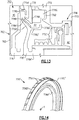
Figure 2 illustrates a bearingassembly 60 according to an example. The bearingassembly 60 can be incorporated into thegas turbine engine 20, such as one of the bearingsystems 38, for example. The bearing assemblies disclosed herein can reduce a likelihood of lubricant flowing into air cavities adjacent to the bearing assembly and also from reducing a likelihood of debris entering into the bearing assembly and interacting with one or more of the bearings situated therein. Other components of theengine 20 and other systems may benefit from the teachings herein, such as a towershaft coupled to one of theshafts - The bearing
assembly 60 includes one or more bearings 62 (one shown for illustrative purposes) situated in a bearing compartment BC. The bearing 62 can include one or more components such as a bearingcarrier 63 including rotatable and static portions for supporting rotatable components of thebearing 62. In the illustrated example, thebearing 62 is a ball bearing. Other example bearings can include roller bearings and taper bearings. Thebearing 62 supports ashaft 64 that is situated along a longitudinal axis X. Theshaft 64 can beinner shaft 40 orouter shaft 50 of thespools 30, 32 (Figure 1 ), for example. Theshaft 64 can include one or more portions mechanically attached to each other for rotation about the longitudinal axis X. The longitudinal axis X can be co-axial with the engine central longitudinal axis A (Figure 1 ). - The bearing
assembly 60 includes aseal assembly 66 bounding or otherwise defining a perimeter of the bearing compartment BC. Theseal assembly 66 can be configured to fluidly separate the bearing compartment BC from an adjacent airflow cavity or compartment AC that can be supplied with pressured cooling airflow for cooling various components of theengine 20. Theseal assembly 66 contains or otherwise opposes migration of lubricant from the bearing compartment BC to the airflow compartment AC, thereby reducing a likelihood of degradation of components of theengine 20 or auto-ignition of the lubricant in relative high temperature locations such thecompressor section 24 or the turbine section 28 (Figure 1 ). For the purposes of this disclosure, the term fluid includes particles capable of flowing such as lubricant or air in various states including gas, mist, vapor or liquid form. - The
seal assembly 66 can include abrush seal 68 and alabyrinth seal 70 that each include portions attached to, and extending from, a seal carrier orsupport 72. Theseal support 72 can be attached to a static structure, such ascase 73 or a portion of engine static structure 36 (Figure 1 ). Thelabyrinth seal 70 includes one or more circumferentially swept knife edges orprotrusions 70A situated adjacent to aseal land 70B for establishing a sealing relationship. In the illustrated example, theseal land 70B is attached to, or is otherwise provided by, theseal support 72. Thebrush seal 68 is situated adjacent to sealland 74 that extends axially from thelabyrinth seal 70 to establish a sealing relationship that is sequential with the sealing relationship established by thelabyrinth seal 70. Other seals can be utilized with the teachings herein, such as carbon seals and finger seals. Although labyrinth seals and brush seals may generate relatively greater debris than carbon seals, for example, labyrinth seals and brush seals can be operated at relatively higher rotational speeds. - The bearing
assembly 60 includes at least onedeflector 76 for shielding or otherwise fluidly separating theseal assembly 66 and thebearing 62. Thedeflector 76 is situated axially between the bearing 62 and theseal assembly 66, and is rotatable about the longitudinal axis X with theshaft 64. Thedeflector 76 can include a generally annular or ring-shapeddeflector body 76A that extends about, and is attached to, a circumference of theshaft 64. Thedeflector body 76A can directly abut against the bearingcarrier 63 and/or theseal assembly 66. - The
deflector 76 can include afirst flange 76B and asecond flange 76C each branching from thedeflector body 76A. Thefirst flange 76B extends in a generally radial direction, and thesecond flange 76C extends in a generally axial direction with respect to the longitudinal axis X. Theflanges flange 76C can define one or more raised protrusion orcircumferential ridges 76G defined about an outer periphery of theflange 76C. - The bearing
assembly 60 includes at least onecoalescer 78 that serves to cause lubricant in the form of mist, vapor or aerosol in the bearing compartment BC to coalesce or amalgamate into relatively larger droplets prior to scavenging the coalesced fluid or lubricant. Thecoalescer 78 can reduce windage in adjacent flow paths and create a relatively quiet region for lubricant to be collected and scavenged. Scavenging can occur along a sump or gutter system 79 (depicted schematically in dashed lines) radially outward of the fluid passage FP at a bottom dead center of the bearing compartment BC orengine 20, for example. Thecoalescer 78 can be made of a solid material such as low carbon steel, or can be made of a porous material that serves as a sponge for collecting lubricant particles circulating in the bearing compartment BC. - The
coalescer 78 can be arranged relative to thedeflector 76 to establish a generally circuitous fluid passage FP between theseal assembly 66 and other portions of the bearing compartment BC. In the illustrated example, thefirst flange 76B ofdeflector 76 extends radially between portions of thebearing 62 and thecoalescer 78, and thesecond flange 76C of thedeflector 76 extends axially between portions of thecoalescer 78 and theseal assembly 66 with respect to longitudinal axis X. Thedeflector 76 can be rotatable withshaft 64 to cause fluid in fluid passage FP to impinge on surfaces of thecoalescer 78. - The
coalescer 78 can include a generally annular or ring-shapedcoalescer body 78A that extends about a coalescer axis CA (Figure 3 ). Thecoalescer body 78A is arranged to at least partially extend about thedeflector 76 to bound or otherwise define portions of the fluid passage FP. Thecoalescer body 78A can be mechanically attached to a static structure such as theseal support 72 via one ormore mounting flanges 78F. Various means for attaching can be utilized such as one or more fasteners or welding. - The
coalescer 78 can include acircumferential flange 78B extending from a radial face of thecoalescer body 78A. Thecircumferential flange 78B can be situated radially between portions of the first andsecond flanges deflector 76 and can serve as a drip edge. Theextension 76K offlange 76B has an annular geometry that is swept about the longitudinal axis X to substantially surroundcircumferential flange 78B to impede flow through the fluid passage FP. Theextension 76K can define one or morefluid passages 76D (one shown) extending through a thickness of theextension 76K for migration of fluid in the fluid passage FP. - The
coalescer 78 can include one ormore coalescer paddles 78C for reducing windage in adjacent flow paths. Each of the coalescer paddles 78C can be arranged to extend into apocket 82 defined between thecoalescer body 78A and theseal support 72. In the illustrated example, thepocket 82 is an annular groove or trough that is swept about the longitudinal axis X and has an opening that faces radially inward toward theshaft 64 and longitudinal axis X. Thelabyrinth seal 70 andbrush seal 68 can define a sealing relationship at a location radially inward of thepocket 82. Thepocket 82 can assist in migration of lubricant away from a radial flow field adjacent theshaft 64 and other associated rotatable components, which can improve the collection and scavenging of lubricant. - Referring to
Figure 3 with continued reference toFigure 2 , thecoalescer body 78A includes an arcuatetop portion 78D extending at least about 180 degrees about the coalescer axis CA and joining with anarcuate bottom portion 78E. In the illustrated example, one or more of the coalescer paddles 78C are arranged along thebottom portion 78E, such as along an arc extending between about 15-45 degrees relative to the coalescer axis CA, and thetop portion 78D is free of any coalescer paddles for reducing a likelihood of lubricant dripping down onto theseal assembly 66. In other examples, thetop portion 78D includes one or more coalescer paddles 78C' (shown in dashed lines). The coalescer paddles 78C can extend from a radially extending face or sidewall of thecoalescer body 78A that is opposed to a sidewall of thecoalescer body 78A from which thecircumferential flange 78B extends. In other examples, one ormore coalescer paddles 78C" (shown in dashed lines) extend from a circumferential face of thecoalescer body 78A, such as radially inward from an inner diameter of thecoalescer body 78A. Thecoalescer body 78A can define one ormore passages 78K (see alsoFigure 6B ) for venting fluid between thepocket 82 and other portions of the bearing compartment BC and/or reducing a likelihood of over-pressurization in the fluid passage FP. - Referring to
Figure 4 , a coalescer 78' accordingly to another example is shown illustrating various geometries of coalescer paddles. For example, the coalescer 78' can have one or more generally elongated coalescer paddles 78C' that can have a skewed orientation relative to the inner and/or outer diameters ofcoalescer body 78A'. The coalescer 78' can include one ormore coalescer paddles 78C" having a scoop or generally hooked shaped protrusion to encourage scavenging of lubricant in the flow path FP (Figure 2 ). -
Figures 5A-5B and 6A-6B illustrate various lubricant and debris flow paths established by components of the bearingassembly 60.Figure 5A and 5B illustrate the bearingassembly 60 withdeflector 76 andcoalescer 78 omitted for illustrative purposes. Referring toFigure 5A , the bearingassembly 60 establishes a first fluid path F1 and a second fluid path F2. The first fluid path F1 flows radially outward, such as toward bottom dead center of the bearing compartment BC. The second fluid path F2 is defined through theseal assembly 66 between the bearing compartment BC and the airflow compartment AC. Referring toFigure 5B , bearingassembly 60 establishes a first debris path D1 branching from a second debris path D2. The first debris path D1 extends radially outward. The second debris path D2 is defined through theseal assembly 66 between the airflow chamber AC towards the bearing compartment BC. -
Figures 6A and 6B illustrate the bearingassembly 60 with thedeflector 76 and thecoalescer 78 in the installed position. Referring toFigure 6A , thefirst flange 76B of thedeflector 76 establishes a third fluid path F3 that extends radially outward, such as toward bottom dead center of the bearing compartment BC, to at least partially shield or otherwise fluidly separate the bearing 62 from theseal assembly 66. The various geometries of the deflectors disclosed herein oppose the traversal of lubricant or debris through the bearing compartment BC. - The
deflector 76 and thecoalescer 78 cooperate to define a fourth fluid path F4 extending through the fluid passage FP and that branches from the third fluid path F3. Thedeflector 76 and thecoalescer 78 are arranged such that the fluid passage FP has a generally serpentine geometry connected to theseal assembly 66 to oppose flow of lubricant through the fourth fluid path F4. Thefirst flange 76B and thecircumferential flange 78B cooperate to establish a first section of the fourth fluid path F4. Thesecond flange 76C of thedeflector 76 is coaxial with portions of thecoalescer body 78A to establish a first intermediate section of the fourth fluid path F4. - The
second flange 76C of thedeflector 76 is coaxial with portions of thelabyrinth seal 70 or sealsupport 72 to define a second intermediate section of the fourth fluid path F4. Thelabyrinth seal 70 andbrush seal 68 define a second portion of the fourth fluid path F4 that is in fluid communication with the airflow compartment AC. The intermediate sections of the fourth fluid path F4 connect the first and second sections adjacent to the bearing compartment BC and the airflow compartment AC. - Referring to
Figure 6B , theseal assembly 66 defines a third debris path D3 in communication with the airflow compartment AC, that follows the fluid passage FP between portions of thelabyrinth seal 70 or sealsupport 72 and thesecond flange 76C of thedeflector 76. Thesecond flange 76C routes flow toward a fourth debris path D4 between the coalescer paddles 78C, and a fifth debris path D5 that extends between thecoalescer body 78A andsecond flange 76C, between thecircumferential flange 78B and thefirst flange 76B, and outward to other portions of the bearing compartment BC.Passage 76D of thedeflector 76 can define a sixth debris path D6 for impeding flow of debris through the fluid passage FP, andpassage 78K (shown in dashed lines) of thecoalescer 78 can define a seventh debris path D7 for assisting in migration of flow of debris frompocket 82 toward the fifth debris path D5. - As illustrated by
Figure 6A , the fluid passage FP is defined such that lubricant communicated along the third and fourth fluid paths F3, F4 has a relatively longer and more complex, circuitous route as compared to the first and second fluid paths F1, F2 ofFigure 5A . This arrangement redirects the flow of lubricant or otherwise reduces a likelihood that lubricant will migrate from the bearing compartment BC into the airflow compartment AC. The arrangement of the fluid passage FP also reduces a likelihood that airflow or lubricant in the form of mist, vapor or aerosol in the bearing compartment BC recirculates in a local region of the bearing compartment BC adjacent to theseal assembly 66 prior to being scavenged. The arrangement of the fluid passage FP also increases the collection of lubricant in the form of mist, vapor or aerosol in thepocket 82 for amalgamation bycoalescer 78. - As illustrated by
Figure 6B , the fluid passage FP is defined such that debris that is communicated along the third through seventh debris paths D3-D7 has a relatively longer and more complex, circuitous route as compared to the first and second debris paths D1, D2 ofFigure 5B . This arrangement redirects the flow of debris or otherwise reduces a likelihood that debris with migrate from the airflow compartment AC and/or theseal assembly 66 toward thebearing 62. - Referring to
Figure 7 , a bearingassembly 160 according to a second example is shown. The bearingassembly 160 includes afirst deflector 176 and a second deflector 176' extending about, and is carried by,shaft 164. Thefirst deflector 176 abuts against bearingcarrier 163 and extends radially between portions of bearing 162 andcoalescer 178. The second deflector 176' extends axially between an inner periphery of thecoalescer 178 and portions ofseal assembly 166. The pair of sequentially arrangeddeflectors 176, 176' can improve the effectiveness of shielding theseal assembly 166 and bearing 162 from each other. - Referring to
Figure 8 , abearing arrangement 260 according to a third example is shown. Thebearing arrangement 260 includes afirst deflector 276 and a second deflector 276'. The second deflector 276' can include one or more knife-edge edges 276E' (one shown) extending outwardly from an outer periphery ofsecond flange 276C' that cooperate with aseal land 278G along an inner periphery of coalescer body 278A ofcoalescer 278 to establish a sealing relationship along fluid passage FP in response to relative rotation. Theseal land 278G can be made of an abradable material for contact with knife-edge edge 276E' caused by relative radial movement. The seal relationship can reduce flow of lubricant and debris through the flow path FP. -
Figure 9 illustrates a bearingassembly 360 according to a fourth example. The bearingassembly 360 includes afirst deflector 376 abutting against bearingcarrier 363 and a second deflector 376' situated between thefirst deflector 376 and theseal assembly 366. The deflector 376' includes an axially extendingseal land 376F' that is situated adjacent to acircumferentially extending flange 378B along a radially inner portion of thecoalescer body 378A. Theflange 378B includes one or more ribs along an inner periphery for establishing a wind back sealing relationship with theseal land 376F' of the deflector 376'. -
Figure 10 illustrates a bearingassembly 460 according to a fifth example. The bearingassembly 460 includes afirst deflector 476 and a second deflector 476'. The deflector 476' is attached to, or is otherwise integrally formed with, a portion oflabyrinth seal 470. The deflector 476' can include an axially extendingsecond flange 476C' and a radially extendingfirst flange 476B' branching from thesecond flange 476C'. - In the illustrated example, a coalescer is omitted. Seal support 472 includes a
main body 472A and aflange 472B that extends radially inward with respect to the longitudinal axis X (Figure 2 ). Theflange 472B of the seal support 472 and theflanges 476B', 476C' of the deflector 476' establish portions of the fluid passage FP having a generally serpentine profile. -
Flange 472B extends radially to boundpocket 482.Pocket 482 can be a relatively deep circumferential trough or annular groove that serves as a mist arrester for causing lubricant to migrate away from a radially flow field of the bearingassembly 460 and can be dimensioned to provide coalescence of lubricant for scavenging. Rather, thepocket 482 can serve as a quieting channel that at least partially isolates lubricant in the fluid passage FP that flows generally outwardly from the adjacent radially flow field of the rotating components. For example, thepocket 482 extends radially between afloor 482A and anopening 482B to define afirst distance 481. Theopening 482B provides fluid communication between thepocket 482 and the fluid passage FP. In the illustrated examine ofFigure 10 , thefloor 482A and theopening 482B can each have a generally circumferential geometry swept about longitudinal axis X, with theopening 482B situated radially between thefloor 482A andshaft 462. Thepocket 482 extends axially from thefloor 482A betweenopposed sidewalls 482C to define asecond distance 483. In some examples, a ratio of thefirst distance 481 to thesecond distance 483 is at least about 1:2, such as between 1:1 and 3:1. In other examples, the ratio of the first andsecond distances Flange 472B of the seal support 472 can define adrain passage 472C (shown in dashed lines) that establishes a flow path between thepocket 482 and adjacent portions of the bearing compartment BC for draining lubricant collected in thepocket 482. -
Figure 11 illustrates a bearingassembly 560 according to a sixth example. The bearingassembly 560 includes afirst deflector 576 and a second deflector 576'. In the illustrated example, the second deflector 576' is distinct fromseal assembly 566.Flanges 576B' and/or 576C' can extend axially adistance 583 defined by opposed sidewalls of thepocket 582 such thatpocket 582 is substantially fluidly separated from theseal assembly 566. -
Figure 12 illustrates a bearingassembly 660 according to a seventh example.Seal support 672 defines a circumferential groove orrecess 672D for receiving a hoop-shapedretaining ring 680. The retainingring 680 extends radially inward relative to the longitudinal axis X (Figure 2 ) to boundpocket 682. The retainingring 680 serves as a mist arrestor which assists in trapping lubricant in the form of mist or vapor, for example, within thepocket 682. The retainingring 680 can be situated betweencircumferential ridges 676G of thedeflector 676 to establish a serpentine flow path through the fluid passage FP. -
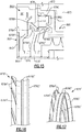
Figure 13 illustrates a bearingassembly 760 according to an eight example. The bearingassembly 760 includes afirst deflector 776 and asecond deflector 776'. Thesecond deflector 776' includes first andsecond flanges 776B', 776C' betweenbearing 762 and sealassembly 766. Thesecond flange 776C' is situated radially between one or more coalescer paddles 778C of thecoalescer 778 and portions of theseal assembly 766.Seal support 772 can define one ormore passages 772E for reducing a likelihood of lubricant hiding or otherwise collecting about portions of theseal assembly 766. - As illustrated by
Figure 14 , thedeflector 776' includes a ring-shapeddeflector body 776A' and an array ofdeflector paddles 776H extending from thefirst flange 776B' and that are situated adjacent tocircumferential flange 778B ofcoalescer 778. Thepaddles 776H' can be circumferentially distributed about an outer periphery of thefirst flange 776B' relative to deflector axis T. The deflector paddles 776H' can provide a pumping action by creating a pressurized field in response to rotation about the longitudinal axis X (Figure 2 ) for moving fluid such as lubricant or airflow in the fluid passage FP away from theseal assembly 766 and back into the bearing compartment BC. Rather, thedeflector paddles 776H' interact withcircumferential flange 778B to establish a hydrodynamic sealing relationship in response to relative rotation. -
Figure 15 illustrates a bearingassembly 860 according to a ninth example. The bearingassembly 860 includes afirst deflector 876 and a second deflector 876'. The second deflector 876' includes one ormore deflector paddles 876H' distributed about a circumference or outer periphery offirst flange 876B' of the deflector 876' for providing a pumping action. The deflector 876' include one or morecircumferential ridges 876G' along thesecond flange 876C' for opposing flow through the fluid passage FP, as illustrated byFigures 16 and 17 . Thecircumferential ridges 876G' can be arranged adjacent to coalescerpaddles 878C ofcoalescer 878 to reduce a rate of flow through the fluid passage FP and for interaction of fluid with the coalescer paddles 878C. -
Figure 18 illustrates a bearingassembly 960 according to a tenth example. The bearingassembly 960 includes afirst deflector 976 and a second deflector 976'. The second deflector 976' includesfirst flange 976B' and asecond flange 976C'. Thesecond flange 976C' includes one ormore deflector paddles 976H' that define one ormore pockets 976J' defined about a circumference of thesecond flange 976C', as seen inFigures 19 and 20 . Thepockets 976J' can be substantially axially aligned with one or more coalescer paddles 978C of thecoalescer 978. The coalescer paddles 978C can extend from an outer periphery of thecircumferential flange 1078J. Thefirst flange 876B' can defineridge 976G' in the form of a circumferential rib having an outer periphery sloping towards the one ormore pockets 976J'. - The arrangement of the
paddles 976H' and pockets 976J' can provide a pumping action to direct airflow and/or lubricant toward surfaces of thecoalescer 978 for coalescence and subsequent scavenging. For example, the deflector 976' can be rotatable with shaft 64 (Figure 2 ) to cause fluid in fluid passage FP to impinge on coalescer paddles 978C. -
Figure 21 illustrates abearing assembly 1060 according to an eleventh example.Coalescer 1078 includes a firstcircumferential flange 1078B and a secondcircumferential flange 1078J each extending from opposed radial faces or sidewalls ofcoalescer body 1078A. In some examples, thecoalescer 1078 can include one ormore coalescer paddles 1078C (one shown in dashed lines). The coalescer paddles 1078C can be distributed about an outer periphery of the secondcircumferential flange 1078J. In alternative examples, thecoalescer 1078 is incorporated intoseal support 1072. -
Figure 22 illustrates abearing assembly 1160 according to a twelfth example. Thebearing assembly 1160 includes a deflector-coalescer assembly 1175 having adeflector 1176 combined or integrated with acoalescer 1178. Thecoalescer 1178 includes acoalescer body 1178A that can have a generally annular or ring-shaped geometry. An inner diameter offlange 1176C ofdeflector 1176 carries thecoalescer 1178 for filtering lubricant particles in fluid passage FP, as seen inFigure 23 . In other examples, thecoalescer 1178 is mechanically attached to another portion of thedeflector 1176, such an outer diameter of theflange 1176C. Thecoalescer 1178 can be made of a sintered metal or a porous membrane such as a metallic sponge, for example, that is press fitted into theflange 1176C. Other techniques for securing thecoalescer 1178 to thedeflector 1176 can be utilized, such as forming a sintered metal or porous membrane on surfaces ofdeflector 1176 along theflange 1176C. - The
flange 1176C defines one ormore deflector pockets 1176P circumferentially distributed about deflector axis T and extending from, or otherwise adjacent to, thecoalescer 1178 for allowing fluid such as lubricant that has been processed by thecoalescer 1178 to pass therethrough for scavenging. The deflector-coalscer assembly 1175 can simplify assembly of thebearing assembly 1160 and installation of theengine 20, for example. Thebearing assembly 1160 can also include coalescer 1178' to process lubricant in the fluid passage FP. In other examples, coalescer 1178' is omitted. - Although a number of embodiments have been described above, other implementations, modifications and variants are possible in light of forgoing teachings. For example, although the bearing assembly, the seal assembly and bearing compartment are primarily discussed with respect to a lubricant flow or airflow, the concepts and teachings herein may be implemented or otherwise used for non-oil applications as well.
- One or more embodiments have been described. Nevertheless, it will be understood that various modifications may be made. For example, when reengineering from a baseline engine configuration, details of the baseline may influence details of any particular implementation. Accordingly, other embodiments are within the scope of the following claims.
Claims (15)
- A bearing assembly (60) comprising:a bearing (62) situated in a bearing compartment (BC);a seal assembly (66) defining the bearing compartment (BC);at least one deflector (76) between the bearing (62) and the seal assembly (66) that is rotatable about an axis (X); anda coalescer (78) at least partially extending about the at least one deflector (76) to define a fluid passage (FP).
- The bearing assembly (60) as recited in claim 1, wherein the at least one deflector (76) is rotatable with a shaft (64) to cause fluid in the fluid passage (FP) to impinge on the coalescer (78).
- The bearing assembly (760; 860; 960) as recited in claim 1 or 2, wherein the at least one deflector (776'; 876'; 976') includes a ring-shaped deflector body (776A'; 876A') and one or more paddles (776H'; 876H'; 976H') extending from the deflector body (776A'; 876A').
- The bearing assembly (960) as recited in claim 1 or 2, wherein the at least one deflector (976') includes a ring-shaped deflector body (76A), a circumferential rib (976G') and one or more pockets (976J') each defined about a circumference of the deflector body, and an outer periphery of the circumferential rib (976G') is sloping towards the one or more pockets (976J').
- The bearing assembly (60) as recited in any preceding claim, wherein the at least one deflector (76) and the coalescer (78) are arranged such that the fluid passage (FP) is a serpentine fluid passage connected to the seal assembly (60).
- The bearing assembly (160; 260; 360; 460; 560; 760; 860; 960) as recited in any preceding claim, wherein the at least one deflector includes a first deflector (176; 276; 376; 476; 576; 776; 876; 976) and a second deflector (176'; 276'; 376'; 476'; 576'; 776'; 876'; 976'), the first deflector (176...976) extending between the bearing and the coalescer (178; 278; 378; 478; 578; 778; 878; 978), and the second deflector (176'...976') extending between an inner periphery of the coalescer (178...978) and portions of the seal assembly (166; 266; 366; 466; 566; 766; 866; 966), wherein, optionally, the second deflector (176'...976') is configured to establish a sealing relationship with the inner periphery of the coalescer (178...978) in response to relative rotation.
- The bearing assembly (60) as recited in any preceding claim, wherein the coalescer (78) includes a ring-shaped coalescer body (78A) and one or more paddles (78C, 78C', 78C") extending from the coalescer body (78A).
- The bearing assembly (1060) as recited in claim 7, wherein the coalescer (1078) includes a first circumferential flange (1078B) and a second circumferential flange (1078J) extending from opposed sidewalls of the coalescer body (1078A), and the one or more paddles (1078C) are distributed about an outer periphery of the second circumferential flange (1078J).
- The bearing assembly (60) as recited in any of claims 1 to 6, wherein:the seal assembly (66) includes a labyrinth seal (70) and a brush seal (68) that oppose flow of lubricant from the bearing compartment (BC);the coalescer (78) includes a ring-shaped coalescer body (78A) that circumferentially extends about the deflector (76) and is attached to a static structure, and includes one or more coalescer paddles (78C, 78C', 78C") extending from a first radially face of the coalescer body (78A), and a or the circumferential flange (78B) extends from a second, opposed radially face of the coalescer body (78A); andthe at least one deflector (76) includes a or the ring-shaped deflector body (76A) extending about a circumference of a shaft (64), and includes a first flange (76B) and a second flange (76C) each branching from the deflector body (76A), the first flange (76B) extending radially between the bearing (62) and the coalescer (78) with respect to the axis (X).
- The bearing assembly (60) as recited in claim 9, wherein:the at least one deflector (76) abuts against a carrier (72) of the bearing (62);the coalescer body (78A) includes an arcuate top portion (78D) extending at least 180 degrees about a coalescer axis (A'), the top portion (78D) being free of any coalescer paddles (78C, 78C', 78C"); andthe second flange (76C) of the at least one deflector (76) is coaxial with portions of the labyrinth seal (170) and an inner periphery of the coalescer body (78A) to define an intermediate section of fluid passage (FP), the fluid passage (FP) including a first section extending through the labyrinth seal (70), a second section extending between the first flange (76B) of the at least one deflector (76) and the circumferential flange (78B) of the coalescer (78), and a intermediate section connecting the first and second sections such that the fluid passage (FP) is a serpentine fluid passage (FP).
- A gas turbine engine (20) comprising:a fan section (22) including a plurality of fan blades;a compressor section (24) in fluid communication with the fan section (22);a turbine section (54) driving the fan section (22) or the compressor section (24) through a rotatable shaft (64); anda bearing assembly (60) supporting the shaft (64), comprising:a bearing (62) situated in a bearing compartment (BC);a seal assembly (66) extending from a seal support (72), the seal support (72) defining a trough extending from a floor, with an opening of the trough situated between the floor and the shaft (64); anda deflector (76) rotatable with the shaft (64) and extending toward the trough, wherein, optionally, the seal assembly (66) includes a labyrinth seal (70) and a brush seal (68) that establish a sealing relationship at a location radially inward of the trough.
- The gas turbine engine (20) as recited in claim 11, wherein the trough is bounded by a coalescer (78) that extends about the deflector (76), wherein, optionally, the coalescer (78) includes one or more coalescer paddles (78C, 78C', 78C") circumferentially distributed about a ring-shaped coalescer body (78A), each of the one or more paddles (78C, 78C', 78C") extending into the trough, and the deflector (76) includes a deflector body (76A) and one or more circumferentially distributed deflector paddles (776H'; 876H'; 976H').
- The gas turbine engine as recited in claim 11, wherein the deflector (76) carries a or the coalescer (78), and defines one or more deflector pockets (976J') adjacent to the coalescer (18).
- A method of sealing for a gas turbine engine (20) comprising:communicating fluid within a bearing compartment (BC) through a fluid passage (FP) defined between a deflector (76) and a coalescer (78); andestablishing a first sealing relationship along the fluid passage (FP).
- The method as recited in claim 14, comprising:coalescing the fluid at the coalescer (78), and communicating coalesced fluid from the coalescer (78) to a gutter system (79) radially outward of the fluid passage (FP); and/orrotating the deflector (76) to cause fluid to impinge on the coalescer (78); and/orrotating the deflector (76) to establish a second sealing relationship along the flow path between the deflector (76) and the coalescer (78).
Priority Applications (1)
| Application Number | Priority Date | Filing Date | Title |
|---|---|---|---|
| EP21185939.2A EP3913196A1 (en) | 2017-06-26 | 2018-06-26 | Bearing assembly for gas turbine engines |
Applications Claiming Priority (1)
| Application Number | Priority Date | Filing Date | Title |
|---|---|---|---|
| US15/632,628 US11028717B2 (en) | 2017-06-26 | 2017-06-26 | Bearing assembly for gas turbine engines |
Related Child Applications (1)
| Application Number | Title | Priority Date | Filing Date |
|---|---|---|---|
| EP21185939.2A Division EP3913196A1 (en) | 2017-06-26 | 2018-06-26 | Bearing assembly for gas turbine engines |
Publications (2)
| Publication Number | Publication Date |
|---|---|
| EP3421737A1 true EP3421737A1 (en) | 2019-01-02 |
| EP3421737B1 EP3421737B1 (en) | 2021-08-04 |
Family
ID=62791657
Family Applications (2)
| Application Number | Title | Priority Date | Filing Date |
|---|---|---|---|
| EP18179970.1A Active EP3421737B1 (en) | 2017-06-26 | 2018-06-26 | Bearing assembly for gas turbine engines |
| EP21185939.2A Pending EP3913196A1 (en) | 2017-06-26 | 2018-06-26 | Bearing assembly for gas turbine engines |
Family Applications After (1)
| Application Number | Title | Priority Date | Filing Date |
|---|---|---|---|
| EP21185939.2A Pending EP3913196A1 (en) | 2017-06-26 | 2018-06-26 | Bearing assembly for gas turbine engines |
Country Status (2)
| Country | Link |
|---|---|
| US (1) | US11028717B2 (en) |
| EP (2) | EP3421737B1 (en) |
Cited By (2)
| Publication number | Priority date | Publication date | Assignee | Title |
|---|---|---|---|---|
| EP3543470A1 (en) * | 2018-03-23 | 2019-09-25 | United Technologies Corporation | Gas turbine engine having a sealing member |
| EP3712395A1 (en) * | 2019-03-18 | 2020-09-23 | United Technologies Corporation | Seal assembly for a gas turbine engine |
Families Citing this family (4)
| Publication number | Priority date | Publication date | Assignee | Title |
|---|---|---|---|---|
| US11306726B2 (en) | 2019-03-11 | 2022-04-19 | Emerson Climate Technologies, Inc. | Foil bearing assembly and compressor including same |
| US11280208B2 (en) * | 2019-08-14 | 2022-03-22 | Pratt & Whitney Canada Corp. | Labyrinth seal assembly |
| US11319836B2 (en) * | 2019-08-14 | 2022-05-03 | Pratt & Whitney Canada Corp. | Lubricant drain conduit for gas turbine engine |
| US20240068338A1 (en) * | 2022-08-30 | 2024-02-29 | Aramco Overseas Company Uk Ltd | Electrical submersible pumping system (esp) motor oil slinger |
Citations (4)
| Publication number | Priority date | Publication date | Assignee | Title |
|---|---|---|---|---|
| EP1045178A2 (en) * | 1999-04-14 | 2000-10-18 | Rolls-Royce Deutschland GmbH | Hydraulic sealing arrangement in particular for gas turbine |
| EP1724445A2 (en) * | 2005-05-06 | 2006-11-22 | General Electric Company | Apparatus for scavenging lubricating oil |
| US20090133581A1 (en) * | 2007-11-28 | 2009-05-28 | General Electric Company | Vortex air-oil separator system |
| EP2157289A2 (en) * | 2008-07-31 | 2010-02-24 | General Electric Company | Pumping impeller oil seal |
Family Cites Families (10)
| Publication number | Priority date | Publication date | Assignee | Title |
|---|---|---|---|---|
| US5749584A (en) * | 1992-11-19 | 1998-05-12 | General Electric Company | Combined brush seal and labyrinth seal segment for rotary machines |
| DE10148000A1 (en) | 2001-09-28 | 2003-04-10 | Rolls Royce Deutschland | oil separator |
| FR2957976B1 (en) | 2010-03-26 | 2013-04-12 | Snecma | SEALING DEVICE FOR AN OIL ENCLOSURE OF A TURBOJET ENGINE |
| KR101284925B1 (en) | 2011-11-21 | 2013-07-17 | 한국수자원공사 | Oil mist reduction device |
| US8366382B1 (en) | 2012-01-31 | 2013-02-05 | United Technologies Corporation | Mid-turbine frame buffer system |
| US20140119887A1 (en) | 2012-11-01 | 2014-05-01 | United Technologies Corporation | Fluid-cooled seal arrangement for a gas turbine engine |
| FR2998922B1 (en) | 2012-12-05 | 2018-06-15 | Safran Aircraft Engines | SEALING OF TURBOMACHINE SPEAKERS REALIZED BY BRUSH JOINT AND LABYRINTH |
| US9677423B2 (en) | 2014-06-20 | 2017-06-13 | Solar Turbines Incorporated | Compressor aft hub sealing system |
| CA2911812A1 (en) | 2014-12-09 | 2016-06-09 | Phillip H. Burnside | Oil flow enhancer bearing assembly |
| FR3035154B1 (en) | 2015-04-17 | 2017-05-05 | Snecma | SEALING DEVICE FOR TURBOMACHINE BEARING OIL ENCLOSURE |
-
2017
- 2017-06-26 US US15/632,628 patent/US11028717B2/en active Active
-
2018
- 2018-06-26 EP EP18179970.1A patent/EP3421737B1/en active Active
- 2018-06-26 EP EP21185939.2A patent/EP3913196A1/en active Pending
Patent Citations (4)
| Publication number | Priority date | Publication date | Assignee | Title |
|---|---|---|---|---|
| EP1045178A2 (en) * | 1999-04-14 | 2000-10-18 | Rolls-Royce Deutschland GmbH | Hydraulic sealing arrangement in particular for gas turbine |
| EP1724445A2 (en) * | 2005-05-06 | 2006-11-22 | General Electric Company | Apparatus for scavenging lubricating oil |
| US20090133581A1 (en) * | 2007-11-28 | 2009-05-28 | General Electric Company | Vortex air-oil separator system |
| EP2157289A2 (en) * | 2008-07-31 | 2010-02-24 | General Electric Company | Pumping impeller oil seal |
Cited By (5)
| Publication number | Priority date | Publication date | Assignee | Title |
|---|---|---|---|---|
| EP3543470A1 (en) * | 2018-03-23 | 2019-09-25 | United Technologies Corporation | Gas turbine engine having a sealing member |
| US10858955B2 (en) | 2018-03-23 | 2020-12-08 | Raytheon Technologies Corporation | Gas turbine engine having a sealing member |
| EP3859125A3 (en) * | 2018-03-23 | 2021-08-18 | Raytheon Technologies Corporation | Gas turbine engine having a sealing member |
| EP3712395A1 (en) * | 2019-03-18 | 2020-09-23 | United Technologies Corporation | Seal assembly for a gas turbine engine |
| US11248492B2 (en) | 2019-03-18 | 2022-02-15 | Raytheon Technologies Corporation | Seal assembly for a gas turbine engine |
Also Published As
| Publication number | Publication date |
|---|---|
| US20180371929A1 (en) | 2018-12-27 |
| EP3913196A1 (en) | 2021-11-24 |
| US11028717B2 (en) | 2021-06-08 |
| EP3421737B1 (en) | 2021-08-04 |
Similar Documents
| Publication | Publication Date | Title |
|---|---|---|
| EP3421737B1 (en) | Bearing assembly for gas turbine engines | |
| EP2809908B1 (en) | Mid-turbine frame buffer system | |
| US11365648B2 (en) | Integral gutter and front center body | |
| EP2299092B1 (en) | Air Particle Separator for a Gas Turbine Engine | |
| US20190271236A1 (en) | Fluid collection gutter for a geared turbine engine | |
| US10767560B2 (en) | Bearing compartment oil auto-ignition mitigation | |
| EP3473893B1 (en) | Lubrication fluid collection in a gearbox of a gas turbine engine | |
| EP3851653A1 (en) | Geared architecture gas turbine engine with planetary gear oil scavenge | |
| US11066945B2 (en) | Fluid collection gutter for a geared turbine engine | |
| EP3708794B1 (en) | Dual radial scoop oil delivery system | |
| EP3190266B1 (en) | Gas turbine engine comprising a rotor hub seal | |
| US10247020B2 (en) | Fluid collection gutter for a geared turbine engine | |
| EP3318722B1 (en) | Seal assembly for a rotatable component | |
| EP3643887B1 (en) | Gas turbine engine seal assemblies | |
| EP3719268A1 (en) | Seal runner with deflector and catcher for gas turbine engine | |
| US10309251B2 (en) | Interlocking rotor assembly with thermal shield | |
| EP3896264A2 (en) | Partial arc gutter for gas turbine engine | |
| EP3812555A1 (en) | Oil drainback arrangement for gas turbine engine | |
| EP3783203A1 (en) | Gas turbine engine bearing compartment comprising a radial seal arrangement with axially elongated oil cooled runner |
Legal Events
| Date | Code | Title | Description |
|---|---|---|---|
| PUAI | Public reference made under article 153(3) epc to a published international application that has entered the european phase |
Free format text: ORIGINAL CODE: 0009012 |
|
| STAA | Information on the status of an ep patent application or granted ep patent |
Free format text: STATUS: THE APPLICATION HAS BEEN PUBLISHED |
|
| AK | Designated contracting states |
Kind code of ref document: A1 Designated state(s): AL AT BE BG CH CY CZ DE DK EE ES FI FR GB GR HR HU IE IS IT LI LT LU LV MC MK MT NL NO PL PT RO RS SE SI SK SM TR |
|
| AX | Request for extension of the european patent |
Extension state: BA ME |
|
| STAA | Information on the status of an ep patent application or granted ep patent |
Free format text: STATUS: REQUEST FOR EXAMINATION WAS MADE |
|
| 17P | Request for examination filed |
Effective date: 20190702 |
|
| RBV | Designated contracting states (corrected) |
Designated state(s): AL AT BE BG CH CY CZ DE DK EE ES FI FR GB GR HR HU IE IS IT LI LT LU LV MC MK MT NL NO PL PT RO RS SE SI SK SM TR |
|
| STAA | Information on the status of an ep patent application or granted ep patent |
Free format text: STATUS: EXAMINATION IS IN PROGRESS |
|
| 17Q | First examination report despatched |
Effective date: 20200221 |
|
| STAA | Information on the status of an ep patent application or granted ep patent |
Free format text: STATUS: EXAMINATION IS IN PROGRESS |
|
| GRAP | Despatch of communication of intention to grant a patent |
Free format text: ORIGINAL CODE: EPIDOSNIGR1 |
|
| STAA | Information on the status of an ep patent application or granted ep patent |
Free format text: STATUS: GRANT OF PATENT IS INTENDED |
|
| INTG | Intention to grant announced |
Effective date: 20201104 |
|
| GRAJ | Information related to disapproval of communication of intention to grant by the applicant or resumption of examination proceedings by the epo deleted |
Free format text: ORIGINAL CODE: EPIDOSDIGR1 |
|
| STAA | Information on the status of an ep patent application or granted ep patent |
Free format text: STATUS: EXAMINATION IS IN PROGRESS |
|
| GRAP | Despatch of communication of intention to grant a patent |
Free format text: ORIGINAL CODE: EPIDOSNIGR1 |
|
| STAA | Information on the status of an ep patent application or granted ep patent |
Free format text: STATUS: GRANT OF PATENT IS INTENDED |
|
| INTC | Intention to grant announced (deleted) | ||
| INTG | Intention to grant announced |
Effective date: 20210208 |
|
| RAP1 | Party data changed (applicant data changed or rights of an application transferred) |
Owner name: RAYTHEON TECHNOLOGIES CORPORATION |
|
| GRAS | Grant fee paid |
Free format text: ORIGINAL CODE: EPIDOSNIGR3 |
|
| GRAA | (expected) grant |
Free format text: ORIGINAL CODE: 0009210 |
|
| STAA | Information on the status of an ep patent application or granted ep patent |
Free format text: STATUS: THE PATENT HAS BEEN GRANTED |
|
| AK | Designated contracting states |
Kind code of ref document: B1 Designated state(s): AL AT BE BG CH CY CZ DE DK EE ES FI FR GB GR HR HU IE IS IT LI LT LU LV MC MK MT NL NO PL PT RO RS SE SI SK SM TR |
|
| REG | Reference to a national code |
Ref country code: GB Ref legal event code: FG4D |
|
| REG | Reference to a national code |
Ref country code: AT Ref legal event code: REF Ref document number: 1417188 Country of ref document: AT Kind code of ref document: T Effective date: 20210815 |
|
| REG | Reference to a national code |
Ref country code: CH Ref legal event code: EP |
|
| REG | Reference to a national code |
Ref country code: DE Ref legal event code: R096 Ref document number: 602018021085 Country of ref document: DE |
|
| REG | Reference to a national code |
Ref country code: IE Ref legal event code: FG4D |
|
| REG | Reference to a national code |
Ref country code: LT Ref legal event code: MG9D |
|
| REG | Reference to a national code |
Ref country code: NL Ref legal event code: MP Effective date: 20210804 |
|
| REG | Reference to a national code |
Ref country code: AT Ref legal event code: MK05 Ref document number: 1417188 Country of ref document: AT Kind code of ref document: T Effective date: 20210804 |
|
| PG25 | Lapsed in a contracting state [announced via postgrant information from national office to epo] |
Ref country code: SE Free format text: LAPSE BECAUSE OF FAILURE TO SUBMIT A TRANSLATION OF THE DESCRIPTION OR TO PAY THE FEE WITHIN THE PRESCRIBED TIME-LIMIT Effective date: 20210804 Ref country code: RS Free format text: LAPSE BECAUSE OF FAILURE TO SUBMIT A TRANSLATION OF THE DESCRIPTION OR TO PAY THE FEE WITHIN THE PRESCRIBED TIME-LIMIT Effective date: 20210804 Ref country code: ES Free format text: LAPSE BECAUSE OF FAILURE TO SUBMIT A TRANSLATION OF THE DESCRIPTION OR TO PAY THE FEE WITHIN THE PRESCRIBED TIME-LIMIT Effective date: 20210804 Ref country code: FI Free format text: LAPSE BECAUSE OF FAILURE TO SUBMIT A TRANSLATION OF THE DESCRIPTION OR TO PAY THE FEE WITHIN THE PRESCRIBED TIME-LIMIT Effective date: 20210804 Ref country code: HR Free format text: LAPSE BECAUSE OF FAILURE TO SUBMIT A TRANSLATION OF THE DESCRIPTION OR TO PAY THE FEE WITHIN THE PRESCRIBED TIME-LIMIT Effective date: 20210804 Ref country code: PT Free format text: LAPSE BECAUSE OF FAILURE TO SUBMIT A TRANSLATION OF THE DESCRIPTION OR TO PAY THE FEE WITHIN THE PRESCRIBED TIME-LIMIT Effective date: 20211206 Ref country code: NO Free format text: LAPSE BECAUSE OF FAILURE TO SUBMIT A TRANSLATION OF THE DESCRIPTION OR TO PAY THE FEE WITHIN THE PRESCRIBED TIME-LIMIT Effective date: 20211104 Ref country code: AT Free format text: LAPSE BECAUSE OF FAILURE TO SUBMIT A TRANSLATION OF THE DESCRIPTION OR TO PAY THE FEE WITHIN THE PRESCRIBED TIME-LIMIT Effective date: 20210804 Ref country code: BG Free format text: LAPSE BECAUSE OF FAILURE TO SUBMIT A TRANSLATION OF THE DESCRIPTION OR TO PAY THE FEE WITHIN THE PRESCRIBED TIME-LIMIT Effective date: 20211104 Ref country code: LT Free format text: LAPSE BECAUSE OF FAILURE TO SUBMIT A TRANSLATION OF THE DESCRIPTION OR TO PAY THE FEE WITHIN THE PRESCRIBED TIME-LIMIT Effective date: 20210804 |
|
| PG25 | Lapsed in a contracting state [announced via postgrant information from national office to epo] |
Ref country code: PL Free format text: LAPSE BECAUSE OF FAILURE TO SUBMIT A TRANSLATION OF THE DESCRIPTION OR TO PAY THE FEE WITHIN THE PRESCRIBED TIME-LIMIT Effective date: 20210804 Ref country code: LV Free format text: LAPSE BECAUSE OF FAILURE TO SUBMIT A TRANSLATION OF THE DESCRIPTION OR TO PAY THE FEE WITHIN THE PRESCRIBED TIME-LIMIT Effective date: 20210804 Ref country code: GR Free format text: LAPSE BECAUSE OF FAILURE TO SUBMIT A TRANSLATION OF THE DESCRIPTION OR TO PAY THE FEE WITHIN THE PRESCRIBED TIME-LIMIT Effective date: 20211105 |
|
| PG25 | Lapsed in a contracting state [announced via postgrant information from national office to epo] |
Ref country code: NL Free format text: LAPSE BECAUSE OF FAILURE TO SUBMIT A TRANSLATION OF THE DESCRIPTION OR TO PAY THE FEE WITHIN THE PRESCRIBED TIME-LIMIT Effective date: 20210804 |
|
| PG25 | Lapsed in a contracting state [announced via postgrant information from national office to epo] |
Ref country code: DK Free format text: LAPSE BECAUSE OF FAILURE TO SUBMIT A TRANSLATION OF THE DESCRIPTION OR TO PAY THE FEE WITHIN THE PRESCRIBED TIME-LIMIT Effective date: 20210804 |
|
| REG | Reference to a national code |
Ref country code: DE Ref legal event code: R097 Ref document number: 602018021085 Country of ref document: DE |
|
| PG25 | Lapsed in a contracting state [announced via postgrant information from national office to epo] |
Ref country code: SM Free format text: LAPSE BECAUSE OF FAILURE TO SUBMIT A TRANSLATION OF THE DESCRIPTION OR TO PAY THE FEE WITHIN THE PRESCRIBED TIME-LIMIT Effective date: 20210804 Ref country code: SK Free format text: LAPSE BECAUSE OF FAILURE TO SUBMIT A TRANSLATION OF THE DESCRIPTION OR TO PAY THE FEE WITHIN THE PRESCRIBED TIME-LIMIT Effective date: 20210804 Ref country code: RO Free format text: LAPSE BECAUSE OF FAILURE TO SUBMIT A TRANSLATION OF THE DESCRIPTION OR TO PAY THE FEE WITHIN THE PRESCRIBED TIME-LIMIT Effective date: 20210804 Ref country code: EE Free format text: LAPSE BECAUSE OF FAILURE TO SUBMIT A TRANSLATION OF THE DESCRIPTION OR TO PAY THE FEE WITHIN THE PRESCRIBED TIME-LIMIT Effective date: 20210804 Ref country code: CZ Free format text: LAPSE BECAUSE OF FAILURE TO SUBMIT A TRANSLATION OF THE DESCRIPTION OR TO PAY THE FEE WITHIN THE PRESCRIBED TIME-LIMIT Effective date: 20210804 Ref country code: AL Free format text: LAPSE BECAUSE OF FAILURE TO SUBMIT A TRANSLATION OF THE DESCRIPTION OR TO PAY THE FEE WITHIN THE PRESCRIBED TIME-LIMIT Effective date: 20210804 |
|
| PLBE | No opposition filed within time limit |
Free format text: ORIGINAL CODE: 0009261 |
|
| STAA | Information on the status of an ep patent application or granted ep patent |
Free format text: STATUS: NO OPPOSITION FILED WITHIN TIME LIMIT |
|
| 26N | No opposition filed |
Effective date: 20220506 |
|
| PG25 | Lapsed in a contracting state [announced via postgrant information from national office to epo] |
Ref country code: IT Free format text: LAPSE BECAUSE OF FAILURE TO SUBMIT A TRANSLATION OF THE DESCRIPTION OR TO PAY THE FEE WITHIN THE PRESCRIBED TIME-LIMIT Effective date: 20210804 |
|
| PG25 | Lapsed in a contracting state [announced via postgrant information from national office to epo] |
Ref country code: SI Free format text: LAPSE BECAUSE OF FAILURE TO SUBMIT A TRANSLATION OF THE DESCRIPTION OR TO PAY THE FEE WITHIN THE PRESCRIBED TIME-LIMIT Effective date: 20210804 |
|
| PG25 | Lapsed in a contracting state [announced via postgrant information from national office to epo] |
Ref country code: MC Free format text: LAPSE BECAUSE OF FAILURE TO SUBMIT A TRANSLATION OF THE DESCRIPTION OR TO PAY THE FEE WITHIN THE PRESCRIBED TIME-LIMIT Effective date: 20210804 |
|
| REG | Reference to a national code |
Ref country code: CH Ref legal event code: PL |
|
| REG | Reference to a national code |
Ref country code: BE Ref legal event code: MM Effective date: 20220630 |
|
| PG25 | Lapsed in a contracting state [announced via postgrant information from national office to epo] |
Ref country code: LU Free format text: LAPSE BECAUSE OF NON-PAYMENT OF DUE FEES Effective date: 20220626 Ref country code: LI Free format text: LAPSE BECAUSE OF NON-PAYMENT OF DUE FEES Effective date: 20220630 Ref country code: IE Free format text: LAPSE BECAUSE OF NON-PAYMENT OF DUE FEES Effective date: 20220626 Ref country code: CH Free format text: LAPSE BECAUSE OF NON-PAYMENT OF DUE FEES Effective date: 20220630 |
|
| PG25 | Lapsed in a contracting state [announced via postgrant information from national office to epo] |
Ref country code: BE Free format text: LAPSE BECAUSE OF NON-PAYMENT OF DUE FEES Effective date: 20220630 |
|
| P01 | Opt-out of the competence of the unified patent court (upc) registered |
Effective date: 20230521 |
|
| PGFP | Annual fee paid to national office [announced via postgrant information from national office to epo] |
Ref country code: FR Payment date: 20230523 Year of fee payment: 6 Ref country code: DE Payment date: 20230523 Year of fee payment: 6 |
|
| PGFP | Annual fee paid to national office [announced via postgrant information from national office to epo] |
Ref country code: GB Payment date: 20230523 Year of fee payment: 6 |
|
| PG25 | Lapsed in a contracting state [announced via postgrant information from national office to epo] |
Ref country code: HU Free format text: LAPSE BECAUSE OF FAILURE TO SUBMIT A TRANSLATION OF THE DESCRIPTION OR TO PAY THE FEE WITHIN THE PRESCRIBED TIME-LIMIT; INVALID AB INITIO Effective date: 20180626 |
|
| PG25 | Lapsed in a contracting state [announced via postgrant information from national office to epo] |
Ref country code: MK Free format text: LAPSE BECAUSE OF FAILURE TO SUBMIT A TRANSLATION OF THE DESCRIPTION OR TO PAY THE FEE WITHIN THE PRESCRIBED TIME-LIMIT Effective date: 20210804 Ref country code: CY Free format text: LAPSE BECAUSE OF FAILURE TO SUBMIT A TRANSLATION OF THE DESCRIPTION OR TO PAY THE FEE WITHIN THE PRESCRIBED TIME-LIMIT Effective date: 20210804 |