EP3421358A1 - Rotor for a hover-capable aircraft - Google Patents
Rotor for a hover-capable aircraft Download PDFInfo
- Publication number
- EP3421358A1 EP3421358A1 EP17179162.7A EP17179162A EP3421358A1 EP 3421358 A1 EP3421358 A1 EP 3421358A1 EP 17179162 A EP17179162 A EP 17179162A EP 3421358 A1 EP3421358 A1 EP 3421358A1
- Authority
- EP
- European Patent Office
- Prior art keywords
- mast
- axis
- rotation
- mass
- rotor
- Prior art date
- Legal status (The legal status is an assumption and is not a legal conclusion. Google has not performed a legal analysis and makes no representation as to the accuracy of the status listed.)
- Granted
Links
Images




Classifications
-
- B—PERFORMING OPERATIONS; TRANSPORTING
- B64—AIRCRAFT; AVIATION; COSMONAUTICS
- B64C—AEROPLANES; HELICOPTERS
- B64C27/00—Rotorcraft; Rotors peculiar thereto
-
- B—PERFORMING OPERATIONS; TRANSPORTING
- B64—AIRCRAFT; AVIATION; COSMONAUTICS
- B64C—AEROPLANES; HELICOPTERS
- B64C27/00—Rotorcraft; Rotors peculiar thereto
- B64C27/001—Vibration damping devices
-
- B—PERFORMING OPERATIONS; TRANSPORTING
- B64—AIRCRAFT; AVIATION; COSMONAUTICS
- B64C—AEROPLANES; HELICOPTERS
- B64C27/00—Rotorcraft; Rotors peculiar thereto
- B64C27/04—Helicopters
- B64C27/08—Helicopters with two or more rotors
-
- B—PERFORMING OPERATIONS; TRANSPORTING
- B64—AIRCRAFT; AVIATION; COSMONAUTICS
- B64C—AEROPLANES; HELICOPTERS
- B64C27/00—Rotorcraft; Rotors peculiar thereto
- B64C27/32—Rotors
-
- F—MECHANICAL ENGINEERING; LIGHTING; HEATING; WEAPONS; BLASTING
- F16—ENGINEERING ELEMENTS AND UNITS; GENERAL MEASURES FOR PRODUCING AND MAINTAINING EFFECTIVE FUNCTIONING OF MACHINES OR INSTALLATIONS; THERMAL INSULATION IN GENERAL
- F16F—SPRINGS; SHOCK-ABSORBERS; MEANS FOR DAMPING VIBRATION
- F16F15/00—Suppression of vibrations in systems; Means or arrangements for avoiding or reducing out-of-balance forces, e.g. due to motion
- F16F15/10—Suppression of vibrations in rotating systems by making use of members moving with the system
-
- F—MECHANICAL ENGINEERING; LIGHTING; HEATING; WEAPONS; BLASTING
- F16—ENGINEERING ELEMENTS AND UNITS; GENERAL MEASURES FOR PRODUCING AND MAINTAINING EFFECTIVE FUNCTIONING OF MACHINES OR INSTALLATIONS; THERMAL INSULATION IN GENERAL
- F16H—GEARING
- F16H1/00—Toothed gearings for conveying rotary motion
- F16H1/02—Toothed gearings for conveying rotary motion without gears having orbital motion
- F16H1/04—Toothed gearings for conveying rotary motion without gears having orbital motion involving only two intermeshing members
- F16H1/06—Toothed gearings for conveying rotary motion without gears having orbital motion involving only two intermeshing members with parallel axes
-
- F—MECHANICAL ENGINEERING; LIGHTING; HEATING; WEAPONS; BLASTING
- F16—ENGINEERING ELEMENTS AND UNITS; GENERAL MEASURES FOR PRODUCING AND MAINTAINING EFFECTIVE FUNCTIONING OF MACHINES OR INSTALLATIONS; THERMAL INSULATION IN GENERAL
- F16H—GEARING
- F16H1/00—Toothed gearings for conveying rotary motion
- F16H1/02—Toothed gearings for conveying rotary motion without gears having orbital motion
- F16H1/04—Toothed gearings for conveying rotary motion without gears having orbital motion involving only two intermeshing members
- F16H1/12—Toothed gearings for conveying rotary motion without gears having orbital motion involving only two intermeshing members with non-parallel axes
- F16H1/16—Toothed gearings for conveying rotary motion without gears having orbital motion involving only two intermeshing members with non-parallel axes comprising worm and worm-wheel
-
- F—MECHANICAL ENGINEERING; LIGHTING; HEATING; WEAPONS; BLASTING
- F16—ENGINEERING ELEMENTS AND UNITS; GENERAL MEASURES FOR PRODUCING AND MAINTAINING EFFECTIVE FUNCTIONING OF MACHINES OR INSTALLATIONS; THERMAL INSULATION IN GENERAL
- F16H—GEARING
- F16H1/00—Toothed gearings for conveying rotary motion
- F16H1/28—Toothed gearings for conveying rotary motion with gears having orbital motion
-
- B—PERFORMING OPERATIONS; TRANSPORTING
- B64—AIRCRAFT; AVIATION; COSMONAUTICS
- B64C—AEROPLANES; HELICOPTERS
- B64C27/00—Rotorcraft; Rotors peculiar thereto
- B64C27/001—Vibration damping devices
- B64C2027/004—Vibration damping devices using actuators, e.g. active systems
-
- B—PERFORMING OPERATIONS; TRANSPORTING
- B64—AIRCRAFT; AVIATION; COSMONAUTICS
- B64C—AEROPLANES; HELICOPTERS
- B64C27/00—Rotorcraft; Rotors peculiar thereto
- B64C27/001—Vibration damping devices
- B64C2027/005—Vibration damping devices using suspended masses
Definitions
- the present invention relates to a rotor for a hover-capable aircraft, in particular to a rotor for a helicopter.
- Helicopters are known to basically comprise a fuselage, a main rotor positioned on the top of the fuselage and rotatable about its own axis, and a tail rotor located at the end of the fuselage.
- the rotor in turn, basically comprises a hub rotatable about the aforementioned axis and equipped with a plurality of blades radially fastened to and projecting from the aforesaid hub, and a mast that can be connected to a drive member and operatively connected to the hub to drive it in rotation.
- operation of the rotor causes the creation of high and low frequency vibrations. More specifically, low-frequency vibrations are generated by the wash separating from the blades and from the centre of the hub. This separation takes place at the centre of the hub and affects all the vertical and horizontal aerodynamic surfaces of the tail and the tail rotor.
- the vibratory loads act on both the hub and the mast, both axially and orthogonally to the mast's axis of rotation.
- the vibratory loads acting in the plane of the rotor have pulses equal to (N+1)* ⁇ , (N-1)* ⁇ and multiples thereof, where ⁇ is the speed of rotation of the mast and N represents the number of blades of the rotor. It is also known that in passing from the rotating system to the fixed system of the fuselage, the vibratory loads acting in the plane of the rotor undergo a frequency shift and have pulses equal to N* ⁇ and associated multiples thereof on the fixed system. In other words, the hub and the mast transfer the vibratory aerodynamic load pulses acting in the plane of the blades onto the aforesaid pulses.
- Passive damping devices basically comprise masses elastically suspended from the mast or the hub. The vibration of these suspended masses enables at least partially dissipating vibration on the mast and the hub.
- passive damping devices Although they are simple to build and install and do not require energy sources outside the rotor, passive damping devices have maximum limits regarding the performance they can offer.
- Active damping devices are fundamentally actuators that exert a sinusoidal damping force on the hub or on the mast, which counters the force generated by the vibrations.
- This patent application illustrates the use of a pair of actuators operatively connected to the mast and controlled so as to generate respective damping forces on the mast having components in the plane orthogonal to the mast's axis of rotation.
- the actuators are shaped like rings, one on top of the other, are driven in rotation by the mast and rotatably mounted with respect to the mast about the axis of rotation.
- the actuators turn in counter rotation about the mast's axis of rotation and generate respective forces on the mast, equal to the product of the mast's speed of rotation and the rotor's number of blades, to counter the aforementioned angular frequency.
- Active damping devices have the advantage of being able to modify their damping characteristics according to the development of the vibratory conditions of the hub and the mast.
- active damping devices are intrinsically more complex than passive damping devices, in terms of weight, power and bulk. Moreover, they need to be powered with a considerable amount of energy.
- the object of the present invention is to produce a rotor for an aircraft capable of hovering that enables satisfying at least one of the above-specified needs in a simple and inexpensive manner.
- reference numeral 1 indicates a hover-capable aircraft, in particular a helicopter basically comprising a fuselage 2, a main rotor 3 positioned on the top of the fuselage 2 and rotating about an axis A, and a tail rotor 4 located at one end of the fuselage 2 and rotating about its own axis, transversal to axis A.
- the rotor 3 comprises a hollow hub 5, with an axis A, carrying a plurality of cantilever-mounted blades 9, which extend radially to axis A.
- the rotor 3 also comprises a mast 6, rotatable about axis A with angular speed ⁇ with respect to a reference system integral with the fuselage 2, angularly integral with the hub 5, and coupled, in a manner not shown, with a drive member, for example a turbine, carried by the helicopter 1.
- a drive member for example a turbine
- the mast 6 is partly housed inside the hub 5 and is angularly integral with the hub 5 ( Figure 2 ).
- the mast 6 is angularly integral with the hub 5 by means of a splined profile 7 and a pair of wedges 8 radially interposed between the mast 6 and the hub 5.
- the splined profile 7 is axially interposed between the aforesaid wedges 8.
- the mast 6 is hollow.
- the main rotor 3 also comprises a flow conveyor 10 designed to guide the airflow generated by the rotation of the rotor 3 according to a predetermined path shaped so as to limit the vibrations generated by separation of the aforesaid flow from the tips of the blades 9 located on the opposite end to the hub 5.
- the flow conveyor 10 is annular, extends around axis A and is located on the opposite side of the hub 5 with respect to the fuselage 2.
- the flow conveyor 10 has a "hat-like" shape and is delimited by a pair of surfaces 11 and 12 axially facing each other; more specifically, surface 11 axially delimits the flow conveyor 10 on the opposite side to the hub 5, while surface 12 axially delimits the flow conveyor 10 on the side closest the hub 5.
- Surface 11 is continuous and extends, proceeding in a radial direction starting from axis A, at an axially decreasing distance from the hub 5.
- Surface 12 has a first circular peripheral edge 13 and a second peripheral edge (not shown in Figure 2 ), opposite to edge 13 and arranged radially outermost to peripheral edge 13. Furthermore, the second peripheral edge of surface 12 axially faces a peripheral edge of surface 11.
- Surfaces 11 and 12 are shaped in such a way that that their axial distance decreases when proceeding in a radial direction starting from axis A.
- surface 12 when proceeding from edge 13 towards the second edge, first moves away from the hub 5 and then moves closer to the hub 5.
- Surfaces 11 and 12 are connected to each other by a tubular body 14, symmetrical with respect to axis A and having a lateral surface extending between surfaces 11 and 12.
- the rotor 3 further comprises a vibration-damping device 15 for damping the transmission of vibrations to the mast 6 in a plane orthogonal to axis A.
- the device 15 dampens the flexural vibrations of the mast 6.
- the device 15 comprises a pair of masses 20a, 20b and a pair of masses 21a, 21b, which can eccentrically rotate about axis A with a first and a second angular speed.
- the masses 20a, 20b; 21a, 21b are connected to the mast 6.
- masses 20a, 20b generate first damping forces on the mast 6 and masses 21a, 21b generate second damping forces on the mast 6.
- the first and second damping forces correspond to the centrifugal forces generated on the mast 6 by the eccentric rotation of the masses 20a, 20b; 21a, 21b on the mast 6.
- first and second damping forces have a sinusoidal course, an amplitude dependent on the magnitude of the respective masses 20a, 20b; 21a, 21b, and on the respective distances of these masses 20a, 20b; 21a, 21b from axis A and the respective rotation speeds about axis A.
- the first and second damping forces generate sull'mast 6 respective first and second resultants with a sinusoidal course, the amplitude and phase of which depend on the angular distance of the respective masses 20a, 20b; 21a, 21b relative to axis A. For example, when the angle between the masses 20a, 20b; 21a, 21b is zero, the first (second) resultant has maximum amplitude. Conversely, when this angle is one hundred and eighty degrees, the first (second) resultant has zero amplitude.
- the masses 20a, 20b are rotatable about axis A with respect to the mast 6 in the same direction of rotation of the mast 6 about axis A and with an angular speed of (N-1)* ⁇ relative to the mast 6, where N is the number of blades 6 and ⁇ is the angular rotation speed of the mast 6.
- the first damping force is sinusoidal with an angular frequency of N* ⁇ with respect to the reference system integral with the fuselage.
- angular frequency means the frequency multiplied by 2n.
- Masses 21a, 21b rotate about axis A in the opposite direction to the direction of rotation of the mast 6 and with an angular frequency of (N+1)* ⁇ relative to the mast 6.
- the angular speed (N-1)* ⁇ is in the same sense as the angular speed ⁇ of the mast 6 and that angular speed (N+1)* ⁇ is in the opposite sense to the angular speed ⁇ of the mast 6, and that the angular speeds (N-1)* ⁇ and (N+1)* ⁇ are to be considered in the reference system integral with the mast 6.
- the first and second damping forces both have angular frequency N* ⁇ in a reference system integral with the fuselage 2.
- This angular frequency N* ⁇ corresponds to the angular frequency of the vibrations to be dampened, i.e. the vibrations transmitted from the blades 9 to the fuselage 2.
- the first damping forces are equal to each other in magnitude and the second damping forces are equal to each other in magnitude.
- the masses 20a, 20b; 21a, 21b are equal to each other in pairs.
- masses 20a and 20b are equal to masses 21a and 21b.
- the masses 20a, 20b; 21a, 21b could have different values from one another.
- the rotor 3 comprises a transmission unit 19 ( Figure 8 ) functionally interposed between the mast 6 and the masses 20a, 20b; 21a, 21b so as to drive the aforesaid masses 20a, 20b; 21a, 21b in rotation, respectively with angular speeds (N-1)* ⁇ ; (N+1)* ⁇ with respect to the mast 6 and in respective mutually opposite directions of rotation.
- the masses 20a, 20b; 21a, 21b can be driven in rotation with the respective rotation speeds (N-1)* ⁇ ; (N+1)* ⁇ without using actuators or energy sources outside the mast 6.
- the transmission unit 19 comprises ( Figure 5 ):
- shafts 30 and 40 rotate about axis A and are housed inside the mast 6.
- Shaft 40 is coaxial with and housed inside shaft 30.
- Shaft 30 rotates in the same direction as the mast 6, while shaft 40 rotates in the opposite direction to the mast 6 and shaft 30.
- the masses 20a, 20b, 21a, 21b are arranged inside the body 14 of the flow conveyor 10, as can be seen in Figure 2 .
- Stages 25, 26 are respective epicyclic trains.
- stage 25 comprises ( Figure 8 to 10 ):
- Stage 25 further comprises:
- the planet-gear carrier 28 comprises a plurality of arms 44; 39 parallel to respective axes C and D and about which the respective planet gears 33, 35; 37 can rotate.
- the mast 6 and shaft 30 turn in the same direction of rotation, thanks to the presence of planet gears 33, 35.
- stage 25 is an epicyclic train, in which:
- Stage 26 further comprises:
- the axes E are radially interposed between respective axes C and D.
- the diameter of planet gears 46 is greater than the diameter of planet gears 48.
- the planet-gear carrier 28 comprises a pair of arms 50 parallel to respective axes E and about which the respective planet gears 46, 48 can rotate.
- stage 26 is an epicyclic train, in which:
- connection groups 60a, 60b; 60c, 60d are housed inside a casing 51 angularly integral with the mast 6 and housed inside the mast 6.
- connection group 60a, 60b, 61b, 61b will be described as these connection groups 60a, 60b, 61a, 61b are identical.
- connection group 60a, 60b (61a, 61b) basically comprises ( Figures 4 , 6 and 7 ):
- the casing 63 also performs the function of containing the oil necessary for lubricating the movement of the shaft 64 and the disc 66, and protecting the worm screw 65.
- the disc 66 is also connected in an angularly integral manner with an associated arm 68 ( Figures 3 and 6 ).
- the arm 68 extends radially from only one side of axis A and carries, overhanging at its opposite end to the axis, the associated mass 20a, 20b (21a, 21b).
- the worm screw 65 and gear teeth 67 of the disc 66 are configured so as to create a condition of irreversible motion.
- rotation of the worm screw 65 about axis B causes rotation of the disc 66 and, therefore, of the mass 20a, 20b (21a, 21b) about axis A by a predetermined angle. Conversely, rotation of the disc 66 about axis A does not cause rotation of the worm screw 65 about axis B.
- the rotor 3 further comprises a plurality of actuators 80a, 80b; 81a, 81b ( Figures 3, 4 , 6 and 7 ) selectively operable to vary the phase and amplitude of the first and second resultant forces generated by the rotation of the mass 20a, 20b; 21a, 21b on the mast 6.
- the actuators 80a, 80b are selectively operable to vary the angle between the masses 20a, 20b about axis A so as to change the phase and amplitude of the first resultant force.
- the actuators 81a, 81b are selectively operable to vary the angle between the masses 21a, 21b about axis A so as to change the phase and amplitude of the second resultant force.
- each actuator 80a, 80b; 81a, 81b comprises:
- the electric motor 82 is housed externally to the associated casing 63.
- the electric motor 82 is angularly integral with the associated casing 63 and, therefore, with shaft 30 (40) about axis A.
- the electric motor 82 rotates about axis A with angular speed (N-1)* ⁇ , ((N+1)* ⁇ ) integral with the shaft 30 (40) and with the casing 63.
- the rotation of the worm screw 65 about axis B causes rotation of the disc 66 and the arm 68 of the associated mass 20a, 20b (21a, 21b) about axis A.
- each actuator 80a, 80b; 81a, 81b through the selective powering on of the relevant electric motor 82, causes an additional rotation of the associated mass 20a, 20b; 21a, 21b about axis A by a predetermined angle with respect to the associated shaft 30; 40.
- This rotation adds to the continual rotation of the masses 20a, 20b; 21a, 21b with respective angular speeds (N-1)* ⁇ ; (N+1)* ⁇ about axis A.
- the rotor 3 further comprises:
- the rotor 3 comprises:
- the mast 6 drives the hub 5 and the blades 9 in rotation about axis A.
- the mast 6 rotates about axis A with angular speed ⁇ , with reference to the reference system integral with the fuselage 2.
- these vibrations mainly have an angular frequency equal to N* ⁇ , where N is the number of blades 9 and ⁇ is the angular rotation speed of the mast 6.
- the mast 6 drives, via the transmission unit 19, the masses 20a, 20b; 21a, 21b in eccentric rotation about axis A with respective angular speeds (N-1)* ⁇ ; (N+1)* ⁇ and in respective directions, in the same and in the opposite direction with respect to the direction of rotation of the mast 6.
- first and the second damping forces are sinusoidal and with respective angular frequencies equal to (N-1)* ⁇ and (N+1)* ⁇ , in the reference system integral with the mast 6.
- first and second damping forces have, in the reference system integral with the fuselage 2, an angular frequency equal to N* ⁇ , i.e. the angular frequency of the disturbing vibratory forces that it is wished to dampen.
- the first and second damping forces generate respective first and second resultants on the mast 6.
- first and second resultants have amplitude and phase dependent on the respective angle between the masses 20a, 20b; 21a, 21b.
- the amplitude of these first and second resultants will be maximum when the angle between the associated masses 20a, 20b; 21a, 21b is zero degrees and minimum when the angle between the associated masses 20a, 20b; 21a, 21b is one hundred and eighty degrees.
- the masses 20a, 20b; 21a, 21b exert the respective first and second resultants on the mast 6 and rotate with respective angular speeds (N-1)* ⁇ ; (N+1)* ⁇ , both when the actuators 80a, 80b; 81a, 81b are activated and when they are deactivated.
- the functioning of the rotor 3 is hereinafter described starting from a state in which the actuators 80a, 80b; 81a, 81b are deactivated.
- the mast 6 drives shaft 30, via stage 25 of the transmission unit 19, and shaft 40, via stage 26 of the transmission unit 19, in rotation about axis A.
- the stages 25 and 26 are sized such that the shafts 30 and 40 rotate with respective angular speeds (N-1)* ⁇ and (N-1)* ⁇ about axis A in the reference system integral with the mast 6.
- mast 6 and shaft 30 rotate in the same direction and shaft 40 rotates in the opposite direction to the mast 6 and shaft 30.
- the shafts 30; 40 drive the masses 20a, 20b; 21a, 21b in rotation about axis A with respective angular speeds (N-1)* ⁇ ; (N-1)* ⁇ by means of the associated connection groups 60a, 60b; 61a, 61b.
- shaft 30 (40) drives in rotation, integrally with itself, and about axis A, the assembly formed by the sleeve 62, the casing 63, the shaft 64, the worm screw 65, the disc 66 and the actuator 80a, 80b (81a, 81b) associated with the respective connection groups 60a, 60b (61a, 61b).
- the worm screw 65 and the disc 66 of the associated connection groups 60a, 60b behave like rigidly connected bodies. This happens because the condition of irreversible motion existing between the worm screw 65 and the gear teeth 67 of the disc 66 prevents inertia of the disc 66 causing relative movement between the worm screw 65 and the gear teeth 67.
- the rotation of the discs 66, via the arms 68, causes the eccentric rotation of the associated masses 20a, 20b; 21a, 21b about axis A with the respective angular speeds (N-1)* ⁇ ; (N+1)* ⁇ .
- the functioning of the rotor 3 is hereinafter described with reference to a state of activation of the actuators 80a, 80b, 81a, 81b.
- the control unit 86 receives signals from the sensors 85 associated with the state of acceleration of the mast 6 and generates control signals for the electric motors 82 of the actuators 80a, 80b; 81a, 81b, in the event of detecting the need to vary the phases and amplitudes of the first and second resultants.
- the activation of one or more electric motors 82 of the actuators 80a, 80b; 81a, 81b causes rotation of the respective output shafts 83 about the respective axes B for predetermined angles.
- One or more output shafts 83 drive the associated shafts 64 and worm screws 65 in rotation, by means of gears 84, about the respective axes B for predetermined angles.
- the rotation of one or more worm screws 65 causes the rotation of one or more discs 66 and, therefore, of one or more masses 20a, 20b; 21a, 21b with respect to the mast 6 and about axis A, by a predetermined angle.
- reference numeral 3' indicates a rotor according to a second embodiment of the present invention.
- Rotor 3' is similar to rotor 3 and will hereinafter be described only with regard to what differentiates it from the latter; the same or equivalent parts of the rotors 3, 3' will be indicated, where possible, by the same reference numbers.
- rotor 3' differs from rotor 3 in that the masses 20a, 20b; 21a, 21b, the actuators 80a, 80b; 81a, 81b and the connection groups 60a, 60b; 61a, 61b are housed inside the body 14 of the flow conveyor 10.
- rotor 3' differs from rotor 3 in that the masses 20a, 20b; 21a, 21b are shaped like respective rollers 22' rotating about respective axes parallel to axis A, mounted in a movable manner with respect to the associated arms 68, radially to axis A, and rolling on respective guides 23' provided in the body 14 of the flow conveyor 10.
- rollers 22' extend around respective axes parallel to axis A and have respective axial ends 24' opposite to each other and radially sliding in corresponding radial slots 18' defined by the free ends of the arms 68.
- rotor 3' The functioning of rotor 3' is entirely similar to that of rotor 3 and is only described with regard to what differs from the functioning of rotor 3.
- rollers 22' defining the masses 20a, 20b; 21a, 21b are pushed by centrifugal force against the guides 23' provided in the body 14.
- rollers 22' can slide, with respect to the associated arms 68, radially to axis A, the centrifugal forces acting on the rollers 22' are discharged on the body 14 of the flow conveyor 10.
- reference numeral 3 indicates a rotor according to a third embodiment of the present invention.
- Rotor 3" is similar to rotor 3 and will hereinafter be described only with regard to what differentiates it from the latter; the same or equivalent parts of the rotors 3, 3" will be indicated, where possible, by the same reference numbers.
- Rotor 3" differ from rotor 3 in that the transmission unit 19" comprises a plurality of stages 90a, 90b; 91a, 91b, which receive motion from the mast 6 rotating with angular speed ⁇ and drive the arm 68 of the associated masses 20a, 20b; 21a, 21b in rotation with the corresponding angular speeds (N-1)* ⁇ ; (N+1)* ⁇ in the reference system integral with the mast 6.
- each stage 90a, 90b comprises:
- Each stage 90c, 90d comprises:
- the planet gears 99c, 99d are rotatable about their own axes I with respect to the common planet-gear carrier 103c.
- Each stage 90a, 90b, 90c, 90d also comprises a broach-like element 104a, 104b, 104c, 104d, which connects a portion of the respective shaft 98a, 98b, 98c, 98d arranged on the axially opposite side with respect to the associated sun gear 97a, 97b, 97c, 97d and radially external with respect to axis A with a portion of the arm 68 of the associated mass 21a, 21b; 20a, 20b arranged radially internal with respect to axis A.
- the ring gear 96a is connected to a flange 110 extending radially outwards from the mast 6.
- the ring gear 96b and the planet-gear carriers 103c are connected to a hollow body 111, which is connected to the mast 6 at the end axially opposite to the flange 110.
- the shafts 98a, 98b, 98c, 98d are arranged in this sequence when proceeding radially on the opposite side of axis A.
- Shaft 98a surrounds the mast 6.
- Body 111 surrounds the shafts 98a, 98b, 98c, 98d, and the mast 6.
- shafts 98a, 98b, 98c, 98d have, in this sequence, decreasing lengths measured parallel to axis A.
- Axes H are radially interposed between axis A and axes I.
- the transmission unit 19" further comprises a casing 120 housing the stages 90a, 90b, 90c, 90d and connected to the fuselage 2 in a way not shown in detail.
- the planet-gear carriers 103a, 103b and the ring gears 96c, 96d are connected to the casing 120 by respective annular bushings 121a, 121b, 121c, 121d coaxial with respect to axis A.
- the bushings 121a, 121b; 121c, 121d are radially interposed between the arms 122; 123 projecting in a cantilever fashion from the casing 120 towards axis A and the respective planet-gear carriers 103a, 103b and the ring gears 96c, 96d.
- Rotor 3" also differs from rotor 3 in that the actuators 80a", 80b", 81a", 81b" are carried by planet-gear carriers 103a, 103b and by ring gears 96c, 96d, respectively.
- Each actuator 80a” , 80b", 81a", 81b" further comprises:
- the mast 6 drives the shafts 98a, 98b in rotation and, therefore, the masses 21a, 21b via the respective stages 90a, 90b.
- the mast 6 also drives shafts 98c, 98d in rotation and, therefore, the masses 20a, 20b via the respective stages 90c, 90d.
- the stages 90c, 90d are sized in such a way that the masses 20a, 20b rotate about axis A with angular speeds (N-1)* ⁇ and the same direction as the direction of rotation of the mast 6.
- the stages 90c, 90d are sized in such a way that the masses 21a, 21b rotate about axis A with angular speeds (N+1)* ⁇ and in the opposite direction to the direction of rotation of the mast 6.
- one or more actuators 80a", 80b", 81a", 81b" are activated, causing the rotation, by a predetermined angle, of the associated one or more worm screws 65 about axis B and of the associated one or more discs 66" about axis A, fixed to an associated planet-gear carrier 103a, 103b or ring gear 96c, 96d.
- This rotation is transmitted to the associated one or more sun gears 97a, 97b, 97c, 97d and, in turn, to the associated one or more masses 20a, 20b, 21a, 21b.
- Rotation of the planet-gear carrier 103, 103b and/or ring gear 96c, 96d about axis A is enabled by the bushings 121a, 121b, 121c, 121d radially interposed between the casing 120 and the planet-gear carriers 103, 103b and/or the ring gear 96c, 96d.
- reference numeral 3"' indicates a rotor according to a fourth embodiment of the present invention.
- Rotor 3"' is similar to rotor 3 and will hereinafter be described only with regard to what differentiates it from the latter; the same or equivalent parts of the rotors 3, 3''' will be indicated, where possible, by the same reference numbers.
- rotor 3''' differs from rotor 3 in that the entire transmission unit 19''', i.e. both stages, is housed inside the body 14 of the flow conveyor 10.
- the masses 20a, 20b; 21a, 21b are driven in rotation by the mast 6 via the transmission unit 19, 19', 19", 19"'.
- the transmission unit 19, 19', 19", 19"' comprises epicyclic trains functionally interposed between the mast 6 and the masses 20a, 20b; 21a, 21b, it is possible to control the speed of rotation of the masses 20a, 20b; 21a, 21b with high precision and repeatability. In consequence, the damping action of the masses 20a, 20b; 21a, 21b is also particularly precise and repeatable.
- the actuators 80a, 80b, 81a, 81b; 80a", 80b", 81a", 81b" enable controlling the phase and amplitude of the first and the second resultants in a wide range of operating conditions of the blades 9.
- each worm screw 65 and the gear teeth 67 of the associated disc 66, 66" is irreversible.
- the rotation of each worm screw 65 about axis B causes rotation of the associated disc 66, 66" - and, consequently, of the associated shaft 30, 40 and the associated masses 20a, 20b; 21a, 21b - about axis A.
- any rotation of the disc 66 about axis A does not cause rotation of the associated worm screw 65 about axis B.
- the disc 66, 66" is mounted in a manner to rotate about axis A with respect to the mast 6.
- the associated worm screws 65 are angularly stationary with respect to axis B and cannot be driven in rotation by the inertia of the discs 66.
- the worm screws 65 and the associated discs 66, 66" behave like rigidly connected bodies and are driven in rotation by shaft 30 (40) with the respective angular speeds (N-1)* ⁇ ((N+1)* ⁇ ).
- rollers 22' forming the masses 20a, 20b; 21a, 21b of rotor 3' are radially movable with respect to the associated arms 68 and radially slide in guides 23'. In this way, the first and second resultants are discharged on the body 14 of the flow conveyor 10 and transferred from the latter to the mast 6.
- the electric motors 82, 82" of the actuators 80a", 80b", 81a", 81a" of rotor 3" are angularly fixed with respect to axis A. In consequence, it is not necessary to provide any slip ring for electrically powering these electric motors 82, 82'', with evident simplification of production and maintenance operations for the rotor 3".
- the rotor 3, 3', 3" , 3"' comprises two pairs of actuators 80a, 80b, 81a, 81b; 80a", 80b", 81a", 81a".
- Rotor 3"' has the entire transmission unit 19"' housed inside the body 14 of the flow conveyor 10, leaving the mast 6 free and simplifying assembly.
- the rotor 3, 3' , 3", 3"' could be used in a convertiplane instead of in a helicopter 1.
- the rotor 3, 3', 3", 3"' could comprise just two masses mounted on respective pantographs operable for adjusting the distance between these masses and axis A and, therefore, control the amplitude and phase of the resultant damping force generated on the mast 6.
- the rotor 3, 3', 3", 3"' could comprise just two masses slidably mounted on respective arms and a pair of guides with a spiral profile in contact with the respective masses.
- the arms are driven in rotation about axis A to adjust the phase of the resultant damping force generated on the mast 6 and the guides are also driven in rotation to adjust the amplitude of this resultant damping force.
- the rotor according to the present invention could be the tail rotor 4 of the helicopter 1 instead of the main rotor 3, 3', 3'', 3'''.
Landscapes
- Engineering & Computer Science (AREA)
- Mechanical Engineering (AREA)
- Aviation & Aerospace Engineering (AREA)
- General Engineering & Computer Science (AREA)
- Physics & Mathematics (AREA)
- Acoustics & Sound (AREA)
- Retarders (AREA)
- Transmission Devices (AREA)
- Connection Of Motors, Electrical Generators, Mechanical Devices, And The Like (AREA)
- Vibration Prevention Devices (AREA)
Abstract
Description
- The present invention relates to a rotor for a hover-capable aircraft, in particular to a rotor for a helicopter.
- Helicopters are known to basically comprise a fuselage, a main rotor positioned on the top of the fuselage and rotatable about its own axis, and a tail rotor located at the end of the fuselage.
- In greater detail, the rotor, in turn, basically comprises a hub rotatable about the aforementioned axis and equipped with a plurality of blades radially fastened to and projecting from the aforesaid hub, and a mast that can be connected to a drive member and operatively connected to the hub to drive it in rotation.
- In use, operation of the rotor causes the creation of high and low frequency vibrations. More specifically, low-frequency vibrations are generated by the wash separating from the blades and from the centre of the hub. This separation takes place at the centre of the hub and affects all the vertical and horizontal aerodynamic surfaces of the tail and the tail rotor.
- In use, rotation of the blades at high angular speeds causes the generation of further high-frequency vibrations, which are transmitted to the mast and, in consequence, to the fuselage, deteriorating comfort for the occupants inside the fuselage.
- More specifically, the vibratory loads act on both the hub and the mast, both axially and orthogonally to the mast's axis of rotation.
- Within the industry, it is known that in the rotating reference system, and thus integral with the rotor, hub and mast, the vibratory loads acting in the plane of the rotor have pulses equal to (N+1)*Ω, (N-1)*Ω and multiples thereof, where Ω is the speed of rotation of the mast and N represents the number of blades of the rotor. It is also known that in passing from the rotating system to the fixed system of the fuselage, the vibratory loads acting in the plane of the rotor undergo a frequency shift and have pulses equal to N*Ω and associated multiples thereof on the fixed system. In other words, the hub and the mast transfer the vibratory aerodynamic load pulses acting in the plane of the blades onto the aforesaid pulses.
- From the foregoing, there is a clearly felt need within the industry for limiting transmission from the mast to the fuselage of vibrations with the aforementioned pulses equal to the product of the mast's speed of rotation and the rotor's number of blades.
- For this purpose, there are known passive and active damping devices.
- Passive damping devices basically comprise masses elastically suspended from the mast or the hub. The vibration of these suspended masses enables at least partially dissipating vibration on the mast and the hub.
- Although they are simple to build and install and do not require energy sources outside the rotor, passive damping devices have maximum limits regarding the performance they can offer.
- Active damping devices are fundamentally actuators that exert a sinusoidal damping force on the hub or on the mast, which counters the force generated by the vibrations.
- An example of these active damping devices is shown in Patent Application
EP-A-2857313 , in the name of the applicant. - This patent application illustrates the use of a pair of actuators operatively connected to the mast and controlled so as to generate respective damping forces on the mast having components in the plane orthogonal to the mast's axis of rotation.
- In greater detail, the actuators are shaped like rings, one on top of the other, are driven in rotation by the mast and rotatably mounted with respect to the mast about the axis of rotation.
- The actuators turn in counter rotation about the mast's axis of rotation and generate respective forces on the mast, equal to the product of the mast's speed of rotation and the rotor's number of blades, to counter the aforementioned angular frequency.
- Further examples of active damping devices are described in Patent Application
US-A-2016/0325828 and in PatentUS-B-8,435200 . - Active damping devices have the advantage of being able to modify their damping characteristics according to the development of the vibratory conditions of the hub and the mast.
- However, active damping devices are intrinsically more complex than passive damping devices, in terms of weight, power and bulk. Moreover, they need to be powered with a considerable amount of energy.
- There is awareness in the industry of the need to dampen flexural vibrations of the mast and the hub, preserving the effectiveness of the aforementioned active damping devices and, at the same time, limiting as far as possible the need for dedicated drive members, so as to reduce weight, bulk and overall costs.
- There is also awareness in the industry of the need to make the value of the damping force exerted on the mast as precise and repeatable as possible, so as to make the vibration damping action as precise and repeatable as possible.
- In addition, there is awareness of the need to be able to adjust the phase and amplitude of the damping force applied to the mast based on the different vibration conditions of the fuselage.
- Finally, there is awareness in the industry of the need to keep the occurrence of undesired vibratory loads in check in the event of failure of one of the drive members.
- The object of the present invention is to produce a rotor for an aircraft capable of hovering that enables satisfying at least one of the above-specified needs in a simple and inexpensive manner.
- The aforesaid object is achieved by the present invention, in so far as it relates to a rotor for a hover-capable aircraft as defined in
claim 1.
For a better understanding of the present invention, four preferred embodiments are described hereinafter, purely by way of a non-limitative example and with reference to the accompanying drawings, in which: -
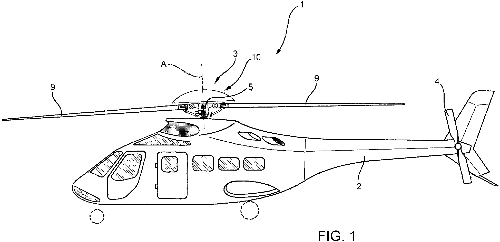
Figure 1 is a side view of a helicopter comprising a rotor according to a first embodiment of the present invention; -
Figure 2 shows, in section, a damping device incorporated in the rotor inFigure 1 , with parts not fully shown for the sake of clarity; -
Figure 3 shows, on an enlarged scale, first components of the rotor inFigure 2 ; -
Figure 4 shows, on a still further enlarged scale, second components of the damping device inFigure 3 ; -
Figure 5 shows, on a highly enlarged scale and in cross-section, certain details of the damping device inFigure 2 ; -
Figure 6 is a top view of the first components inFigure 3 ; -
Figure 7 is a top view of the second components inFigure 4 ; -
Figure 8 is an operating diagram of the first components inFigure 5 ; -
Figure 9 is a section along the line IX-IX inFigure 8 ; -
Figure 10 is a section along the line X-X inFigure 8 ; -
Figure 11 shows, in cross-section, a rotor according to a further embodiment of the present invention, with parts not fully shown for the sake of clarity; -
Figure 12 is a section along the line XII-XII inFigure 11 ; -
Figure 13 shows, in cross-section, a rotor according to a third embodiment of the present invention, with parts removed for clarity; and -
Figure 14 shows, in cross-section, a rotor according to a fourth embodiment of the present invention, with parts removed for clarity. - Referring to
Figure 1 ,reference numeral 1 indicates a hover-capable aircraft, in particular a helicopter basically comprising afuselage 2, amain rotor 3 positioned on the top of thefuselage 2 and rotating about an axis A, and a tail rotor 4 located at one end of thefuselage 2 and rotating about its own axis, transversal to axis A. - In greater detail, the
rotor 3 comprises ahollow hub 5, with an axis A, carrying a plurality of cantilever-mountedblades 9, which extend radially to axis A. - Referring to
Figure 2 , therotor 3 also comprises amast 6, rotatable about axis A with angular speed Ω with respect to a reference system integral with thefuselage 2, angularly integral with thehub 5, and coupled, in a manner not shown, with a drive member, for example a turbine, carried by thehelicopter 1. - More specifically, the
mast 6 is partly housed inside thehub 5 and is angularly integral with the hub 5 (Figure 2 ). - More specifically, the
mast 6 is angularly integral with thehub 5 by means of asplined profile 7 and a pair ofwedges 8 radially interposed between themast 6 and thehub 5. In particular, thesplined profile 7 is axially interposed between theaforesaid wedges 8. - In particular, the
mast 6 is hollow. - The
main rotor 3 also comprises aflow conveyor 10 designed to guide the airflow generated by the rotation of therotor 3 according to a predetermined path shaped so as to limit the vibrations generated by separation of the aforesaid flow from the tips of theblades 9 located on the opposite end to thehub 5. - In greater detail, the
flow conveyor 10 is annular, extends around axis A and is located on the opposite side of thehub 5 with respect to thefuselage 2. - The
flow conveyor 10 has a "hat-like" shape and is delimited by a pair ofsurfaces surface 11 axially delimits theflow conveyor 10 on the opposite side to thehub 5, whilesurface 12 axially delimits theflow conveyor 10 on the side closest thehub 5. -
Surface 11 is continuous and extends, proceeding in a radial direction starting from axis A, at an axially decreasing distance from thehub 5. -
Surface 12 has a first circularperipheral edge 13 and a second peripheral edge (not shown inFigure 2 ), opposite toedge 13 and arranged radially outermost toperipheral edge 13. Furthermore, the second peripheral edge ofsurface 12 axially faces a peripheral edge ofsurface 11. -
Surfaces - More specifically,
surface 12, when proceeding fromedge 13 towards the second edge, first moves away from thehub 5 and then moves closer to thehub 5. -
Surfaces tubular body 14, symmetrical with respect to axis A and having a lateral surface extending betweensurfaces - The
rotor 3 further comprises a vibration-damping device 15 for damping the transmission of vibrations to themast 6 in a plane orthogonal to axis A. In other words, thedevice 15 dampens the flexural vibrations of themast 6. - In greater detail, the
device 15 comprises a pair ofmasses masses - The
masses mast 6. - In this way,
masses mast 6 andmasses mast 6. - The first and second damping forces correspond to the centrifugal forces generated on the
mast 6 by the eccentric rotation of themasses mast 6. - These first and second damping forces have a sinusoidal course, an amplitude dependent on the magnitude of the
respective masses masses - The first and second damping forces generate
sull'mast 6 respective first and second resultants with a sinusoidal course, the amplitude and phase of which depend on the angular distance of therespective masses masses - Preferably, the
masses mast 6 in the same direction of rotation of themast 6 about axis A and with an angular speed of (N-1)*Ω relative to themast 6, where N is the number ofblades 6 and Ω is the angular rotation speed of themast 6. In this way, the first damping force is sinusoidal with an angular frequency of N*Ω with respect to the reference system integral with the fuselage. - In the present description, the term angular frequency means the frequency multiplied by 2n.
-
Masses mast 6 and with an angular frequency of (N+1)*Ω relative to themast 6. - Where not expressly indicated, hereinafter in the present description it is understood that the angular speed (N-1)*Ω is in the same sense as the angular speed Ω of the
mast 6 and that angular speed (N+1)*Ω is in the opposite sense to the angular speed Ω of themast 6, and that the angular speeds (N-1)*Ω and (N+1)*Ω are to be considered in the reference system integral with themast 6. - In this way, the first and second damping forces both have angular frequency N*Ω in a reference system integral with the
fuselage 2. This angular frequency N*Ω corresponds to the angular frequency of the vibrations to be dampened, i.e. the vibrations transmitted from theblades 9 to thefuselage 2. - The first damping forces are equal to each other in magnitude and the second damping forces are equal to each other in magnitude.
- The
masses - In the case shown,
masses masses - In a further embodiment that is not shown, the
masses - Advantageously, the
rotor 3 comprises a transmission unit 19 (Figure 8 ) functionally interposed between themast 6 and themasses aforesaid masses mast 6 and in respective mutually opposite directions of rotation. - In this way, the
masses mast 6. - Preferably, the
transmission unit 19 comprises (Figure 5 ): - a
stage 25 that receives motion from therotating mast 6 with angular speed Ω and has, in output, ashaft 30 angularly integral withmasses 20a; 20b and rotating with speed of rotation (N-1)*Ω in the same direction as the direction of rotation of themast 6; and - a
stage 26 that receives motion fromshaft 30 and has, in output, ashaft 40 angularly integral withmasses 21a; 21b and rotating with speed of rotation (N+1)*Ω in the opposite direction to the direction of rotation of themast 6. - In particular,
shafts mast 6.Shaft 40 is coaxial with and housed insideshaft 30. -
Shaft 30 rotates in the same direction as themast 6, whileshaft 40 rotates in the opposite direction to themast 6 andshaft 30. - In the case shown, the
masses body 14 of theflow conveyor 10, as can be seen inFigure 2 . -
Stages - In greater detail,
stage 25 comprises (Figure 8 to 10 ): - a
tubular casing 27 mounted coaxially inside themast 6 such that it can rotate about axis A at the same angular speed Ω of themast 6 and defininggear teeth 31 radially internal with respect to axis A; - a planet-
gear carrier 28 fixed to thefuselage 2 and therefore angularly fixed with respect to axis A; - a
sun gear 29 rotatable about axis A, defininggear teeth 32 radially external with respect to axis A and angularly integral withshaft 30. -
Stage 25 further comprises: - a plurality, three in the case shown, of planet gears 33, rotatable about their own axes C parallel to axis A, and having respective
outer gear teeth 34 with respect to the associated axes C and meshing with thegear teeth 31 of thecasing 27; and - a plurality, three in the case shown, of planet gears 35, rotatable about their own axes D parallel to the axes A, C, and having respective
outer gear teeth 36 with respect to the associated axes C, each meshing with thegear teeth 34 of arespective planet gear 33. - The planet-
gear carrier 28 comprises a plurality ofarms 44; 39 parallel to respective axes C and D and about which the respective planet gears 33, 35; 37 can rotate. - The
mast 6 andshaft 30 turn in the same direction of rotation, thanks to the presence of planet gears 33, 35. - In other words,
stage 25 is an epicyclic train, in which: - the
casing 27 defines a motion input and forms a ring gear rotating with angular speed Ω about axis A in the reference system integral with thefuselage 2; - the
sun gear 29 rotates with angular speed (N-1)*Ω about axis A and defines a motion output; and - the planet-
gear carrier 28 is angularly fixed with respect to axis A. - a
ring gear 41 housed inside themast 6, axially interposed between thesun gear 29 andshaft 30 and angularly integral with thesun gear 29 andshaft 30, and comprisinginternal gear teeth 42 with respect to axis A; and - a
sun gear 45 rotatable about axis A with angular speed (N+1)*Ω and angularly integral withshaft 40 and comprisingexternal gear teeth 43 with respect to axis A. -
Stage 26 further comprises: - a plurality, three in the case shown, of planet gears 46 rotatable about their own axes E parallel to axis A, and having respective
outer gear teeth 47 with respect to the associated axes E and meshing with thegear teeth 42 of thering gear 41; and - a plurality, three in the case shown, of planet gears 48 angularly integral with the planet gears 46 and having respective
outer gear teeth 49 with respect to the associated axes E and meshing with thegear teeth 43 of thesun gear 45. - In particular, the axes E are radially interposed between respective axes C and D.
- Furthermore, the diameter of planet gears 46 is greater than the diameter of planet gears 48.
- The planet-
gear carrier 28 comprises a pair ofarms 50 parallel to respective axes E and about which the respective planet gears 46, 48 can rotate. - In other words,
stage 26 is an epicyclic train, in which: - the
ring gear 41 defines a motion input with angular speed (N-1)*Ω in the same direction as the direction of rotation of themast 6 and is angularly integral with thesun gear 29 ofstage 25; - the
sun gear 45 rotates with angular speed (N+1)*Ω in the opposite direction to the direction of rotation of themast 6 and defines a motion output; and - the planet-
gear carrier 28 is fixed and is shared withstage 25. -
connection groups shaft 30 and therespective masses - connection groups 61a, 61b for connecting the
shaft 40 and therespective masses - With particular reference to
Figure 6 , theconnection groups casing 51 angularly integral with themast 6 and housed inside themast 6. - In the following, only one
connection group connection groups - The
connection group Figures 4 ,6 and 7 ): - a
sleeve 62 fitted onshaft 30 coaxial with axis A; and - a
casing 63 surrounding thesleeve 62, driven in rotation by thesleeve 62 and angularly connected to themasses - a
shaft 64 rotatable about an axis B orthogonal to and offset from axis A with respect to thecasing 63 and angularly integral with thecasing 63 about axis A; - a
worm screw 65 rotating integrally with theshaft 64 about axis B; and - a
disc 66 mounted in manner angularly movable about axis A with respect to thesleeve 62 and the shaft 30 (40), equipped withhelical gear teeth 67, external with respect to axis A and meshing with theworm screw 65, and angularly integral with themass - The
casing 63 also performs the function of containing the oil necessary for lubricating the movement of theshaft 64 and thedisc 66, and protecting theworm screw 65. - The
disc 66 is also connected in an angularly integral manner with an associated arm 68 (Figures 3 and6 ). Thearm 68 extends radially from only one side of axis A and carries, overhanging at its opposite end to the axis, the associatedmass - The
worm screw 65 andgear teeth 67 of thedisc 66 are configured so as to create a condition of irreversible motion. - In particular, rotation of the
worm screw 65 about axis B causes rotation of thedisc 66 and, therefore, of themass disc 66 about axis A does not cause rotation of theworm screw 65 about axis B. - From the foregoing, it follows that the rotation of
shaft 30 about axis A drives theworm screw 65, thedisc 66 and themasses - It is important to note that the condition of irreversible motion existing between the
worm screw 65 and thegear teeth 67 prevents inertia of thedisc 66 from causing relative movement between theworm screw 65 and thegear teeth 67 when theworm screw 65 is angularly stationary with respect to axis B. In other words, when theworm screw 65 is angularly stationary with respect to axis B, theworm screw 65 and thedisc 66 behave like bodies rigidly connected to each other and rotate integrally about axis A. - Advantageously, the
rotor 3 further comprises a plurality ofactuators Figures 3, 4 ,6 and 7 ) selectively operable to vary the phase and amplitude of the first and second resultant forces generated by the rotation of themass mast 6. - In greater detail, the
actuators masses - The
actuators masses - With particular reference to
Figures 3 to 7 , eachactuator - an
electric motor 82 having anoutput shaft 83 rotatable about an axis parallel to and offset from axis B; and - a
gear 84 interposed between theelectric motor 82 and the associatedshaft 64, and designed to transform rotation of theoutput shaft 83 parallel to axis B into rotation ofshaft 64 and theworm screw 65 about axis B. - The
electric motor 82 is housed externally to the associatedcasing 63. - The
electric motor 82 is angularly integral with the associatedcasing 63 and, therefore, with shaft 30 (40) about axis A. - In consequence, both when switched on and when switched off, the
electric motor 82, rotates about axis A with angular speed (N-1)*Ω, ((N+1)*Ω) integral with the shaft 30 (40) and with thecasing 63. - Conversely, switching on the
electric motor 82 causes rotation ofshafts worm screw 65 about axis B with respect to thecasing 63 and shaft 30 (40). - The rotation of the
worm screw 65 about axis B causes rotation of thedisc 66 and thearm 68 of the associatedmass - In other words, each
actuator electric motor 82, causes an additional rotation of the associatedmass shaft 30; 40. This rotation adds to the continual rotation of themasses - The
rotor 3 further comprises: - a first slip-ring (not shown) to electrically connect a source of electrical power carried on the
fuselage 2 with theelectric motors 82 ofactuators - a second slip-ring (also not shown) to electrically connect the electricity source with the
electric motors 82 ofactuators - Finally, the
rotor 3 comprises: - a plurality of sensors 85 (schematically shown in
Figure 2 ) capable of generating a plurality of signals associated with the state of acceleration of thefuselage 2 in a plane orthogonal to axis A; and - a control unit 86 (also schematically shown in
Figure 2 ) configured to generate, on the basis of one of the signals generated by thesensors 85, a control signal for theactuators - In use, the
mast 6 drives thehub 5 and theblades 9 in rotation about axis A. - More specifically, the
mast 6 rotates about axis A with angular speed Ω, with reference to the reference system integral with thefuselage 2. - The rotation of the
hub 5 and theblades 9 generates vibrations, which would be transmitted to themast 6 and, from there, to thefuselage 2 of thehelicopter 1. - With respect to the fixed system of the fuselage, these vibrations mainly have an angular frequency equal to N*Ω, where N is the number of
blades 9 and Ω is the angular rotation speed of themast 6. - In order to reduce these vibrations, the
mast 6 drives, via thetransmission unit 19, themasses mast 6. - Due to the centrifugal effect, these eccentric rotations of the
masses mast 6. - More specifically, the first and the second damping forces are sinusoidal and with respective angular frequencies equal to (N-1)*Ω and (N+1)*Ω, in the reference system integral with the
mast 6. - These first and second damping forces counter the loads due to these vibrations in a plane orthogonal to axis A.
- Furthermore, these first and second damping forces have, in the reference system integral with the
fuselage 2, an angular frequency equal to N*Ω, i.e. the angular frequency of the disturbing vibratory forces that it is wished to dampen. - The first and second damping forces generate respective first and second resultants on the
mast 6. - These first and second resultants have amplitude and phase dependent on the respective angle between the
masses masses masses - It is important to note that the
masses mast 6 and rotate with respective angular speeds (N-1)*Ω; (N+1)*Ω, both when theactuators - Whereas the selective activation of the
actuators mast 6. - The functioning of the
rotor 3 is hereinafter described starting from a state in which theactuators - The
mast 6 drivesshaft 30, viastage 25 of thetransmission unit 19, andshaft 40, viastage 26 of thetransmission unit 19, in rotation about axis A. - The
stages shafts mast 6. - In particular, the
mast 6 andshaft 30 rotate in the same direction andshaft 40 rotates in the opposite direction to themast 6 andshaft 30. - The
shafts 30; 40 drive themasses connection groups - In greater detail, shaft 30 (40) drives in rotation, integrally with itself, and about axis A, the assembly formed by the
sleeve 62, thecasing 63, theshaft 64, theworm screw 65, thedisc 66 and theactuator respective connection groups - In the state where the
actuators electric motors 82 are not powered and, therefore, theworm screw 65 is angularly stationary with respect to axis B. - In this situation, the
worm screw 65 and thedisc 66 of the associatedconnection groups worm screw 65 and thegear teeth 67 of thedisc 66 prevents inertia of thedisc 66 causing relative movement between theworm screw 65 and thegear teeth 67. - In consequence, in the aforementioned condition, the
discs 66 of theconnection groups - The rotation of the
discs 66, via thearms 68, causes the eccentric rotation of the associatedmasses - The functioning of the
rotor 3 is hereinafter described with reference to a state of activation of theactuators - The
control unit 86 receives signals from thesensors 85 associated with the state of acceleration of themast 6 and generates control signals for theelectric motors 82 of theactuators - The activation of one or more
electric motors 82 of theactuators respective output shafts 83 about the respective axes B for predetermined angles. - One or
more output shafts 83 drive the associatedshafts 64 and worm screws 65 in rotation, by means ofgears 84, about the respective axes B for predetermined angles. - The rotation of one or more worm screws 65 causes the rotation of one or
more discs 66 and, therefore, of one ormore masses mast 6 and about axis A, by a predetermined angle. - Referring to
Figures 11 and 12 , reference numeral 3' indicates a rotor according to a second embodiment of the present invention. - Rotor 3' is similar to
rotor 3 and will hereinafter be described only with regard to what differentiates it from the latter; the same or equivalent parts of therotors 3, 3' will be indicated, where possible, by the same reference numbers. - In particular, rotor 3' differs from
rotor 3 in that themasses actuators connection groups body 14 of theflow conveyor 10. - Furthermore, rotor 3' differs from
rotor 3 in that themasses arms 68, radially to axis A, and rolling on respective guides 23' provided in thebody 14 of theflow conveyor 10. - More specifically, the rollers 22' extend around respective axes parallel to axis A and have respective axial ends 24' opposite to each other and radially sliding in corresponding radial slots 18' defined by the free ends of the
arms 68. - The functioning of rotor 3' is entirely similar to that of
rotor 3 and is only described with regard to what differs from the functioning ofrotor 3. - In particular, the rollers 22' defining the
masses body 14. - Due to the fact that the rollers 22' can slide, with respect to the associated
arms 68, radially to axis A, the centrifugal forces acting on the rollers 22' are discharged on thebody 14 of theflow conveyor 10. - Referring to
Figure 13 ,reference numeral 3" indicates a rotor according to a third embodiment of the present invention. -
Rotor 3" is similar torotor 3 and will hereinafter be described only with regard to what differentiates it from the latter; the same or equivalent parts of therotors -
Rotor 3" differ fromrotor 3 in that thetransmission unit 19" comprises a plurality ofstages mast 6 rotating with angular speed Ω and drive thearm 68 of the associatedmasses mast 6. - In greater detail, each
stage - a
ring gear mast 6 about axis A; - a
sun gear shaft - a plurality, three in the case shown, of
planet gears 99a, 99b rotatable about their own axes H, parallel to and offset from axis A, and havingrespective gear teeth 100a, 100b meshing, on respective opposite sides of the associated axis H, withgear teeth ring gear gear teeth sun gear - a planet-
gear carrier respective planet gears 99a, 99b rotate about their respective axes H. - Each
stage - a
ring gear - a
sun gear shaft - a plurality, three in the case shown, of
planet gears gear teeth ring gear gear teeth sun gear - a planet-
gear carrier 103c, common to thestages mast 6 about axis A, and fixed to thering gear 96b ofstage 90b. - The planet gears 99c, 99d are rotatable about their own axes I with respect to the common planet-
gear carrier 103c. - Each
stage like element respective shaft sun gear arm 68 of the associatedmass - In the case shown, the
ring gear 96a is connected to aflange 110 extending radially outwards from themast 6. - The
ring gear 96b and the planet-gear carriers 103c are connected to ahollow body 111, which is connected to themast 6 at the end axially opposite to theflange 110. - In the case shown, the
shafts -
Shaft 98a surrounds themast 6. -
Body 111 surrounds theshafts mast 6. - Furthermore, the
shafts - Axes H are radially interposed between axis A and axes I.
- The
transmission unit 19" further comprises acasing 120 housing thestages fuselage 2 in a way not shown in detail. - The planet-
gear carriers casing 120 by respectiveannular bushings - In the case shown, the
bushings arms 122; 123 projecting in a cantilever fashion from thecasing 120 towards axis A and the respective planet-gear carriers -
Rotor 3" also differs fromrotor 3 in that theactuators 80a", 80b", 81a", 81b" are carried by planet-gear carriers ring gears - Each
actuator 80a" , 80b", 81a", 81b" further comprises: - an
electric motor 82" having anoutput member 83 rotatable about axis B and on which theworm screw 65 is mounted; and - a
disc 66" havinghelical gear teeth 67" meshing with theworm screw 65 and fixed to the associated planet-gear carrier ring gear - The functioning of
rotor 3" is entirely similar to that ofrotor 3 and is only described with regard to what differs from the functioning ofrotor 3. - In particular, the
mast 6 drives theshafts masses respective stages mast 6 also drivesshafts masses respective stages - In greater detail, the
stages masses mast 6. Thestages masses mast 6. - In the state where the
actuators 80a", 80b", 81a", 81b" are deactivated, the planet-gear carriers casing 120 and, therefore, angularly fixed with respect to axis A. - In these conditions, the angle between the
masses - If the
control unit 86 detects the need to vary the phases or amplitudes of the first and second resultants, one ormore actuators 80a", 80b", 81a", 81b" are activated, causing the rotation, by a predetermined angle, of the associated one or more worm screws 65 about axis B and of the associated one ormore discs 66" about axis A, fixed to an associated planet-gear carrier ring gear more sun gears more masses - Rotation of the planet-
gear carrier 103, 103b and/orring gear bushings casing 120 and the planet-gear carriers 103, 103b and/or thering gear - Referring to
Figure 14 ,reference numeral 3"' indicates a rotor according to a fourth embodiment of the present invention. -
Rotor 3"' is similar torotor 3 and will hereinafter be described only with regard to what differentiates it from the latter; the same or equivalent parts of therotors 3, 3''' will be indicated, where possible, by the same reference numbers. - In particular, rotor 3''' differs from
rotor 3 in that the entire transmission unit 19''', i.e. both stages, is housed inside thebody 14 of theflow conveyor 10. - The functioning of rotor 3''' is identical to that of
rotor 3 and is therefore not described. - From examination of the characteristics of the
rotor - In particular, the
masses mast 6 via thetransmission unit - In this way, it is possible to achieve "active" vibration damping of the
mast 6 in a plane orthogonal to axis A by exploiting the rotation of themast 6 and using theelectric motors respective masses - Due to the fact that the
transmission unit mast 6 and themasses masses masses - The
actuators blades 9. - The coupling between each
worm screw 65 and thegear teeth 67 of the associateddisc worm screw 65 about axis B causes rotation of the associateddisc shaft masses disc 66 about axis A does not cause rotation of the associatedworm screw 65 about axis B. In addition, thedisc mast 6. - Therefore, when the
electric motors discs 66. In this situation, the worm screws 65 and the associateddiscs - Conversely, when the
electric motors discs corresponding masses mast 6 and about axis A by the angles necessary for achieving the desired amplitude and phase values for the first and second resultant forces. - The rollers 22' forming the
masses arms 68 and radially slide in guides 23'. In this way, the first and second resultants are discharged on thebody 14 of theflow conveyor 10 and transferred from the latter to themast 6. - The
electric motors actuators 80a", 80b", 81a", 81a" ofrotor 3" are angularly fixed with respect to axis A. In consequence, it is not necessary to provide any slip ring for electrically powering theseelectric motors 82, 82'', with evident simplification of production and maintenance operations for therotor 3". - The
rotor actuators electric motors 82 connected to one of themasses electric motor 82 associated with the other one ofmasses -
Rotor 3"' has theentire transmission unit 19"' housed inside thebody 14 of theflow conveyor 10, leaving themast 6 free and simplifying assembly. - Finally, it is also clear that modifications and variants can be made regarding the
rotor - In particular, the
rotor helicopter 1. - Furthermore, instead of the
masses rotor mast 6. - Finally, instead of the
masses rotor mast 6 and the guides are also driven in rotation to adjust the amplitude of this resultant damping force. - Finally, the rotor according to the present invention could be the tail rotor 4 of the
helicopter 1 instead of themain rotor 3, 3', 3'', 3'''.
Claims (15)
- A rotor (3, 3', 3", 3''') for a hover-capable aircraft (1), comprising:- a hub (5) rotatable about a first axis (A) and, in turn, comprising a plurality of blades (9);- a mast (6) connectable to a drive member of said aircraft (1) and operatively connected to said hub (5) to drive the hub (5) in rotation about said first axis (A); anddamping means (15; 20a, 20b; 21a, 21b) to dampen the transmission of vibrations to said mast (6) in a plane orthogonal to said first axis (A);
said damping means (15; 20a, 20b; 21a, 21b) in turn comprising at least one first mass (20a, 20b) and at least one second mass (21a, 21b) that can eccentrically rotate about said first axis (A), respectively with a first and a second speed of rotation ((N-1)*Ω; -(N+1)*Ω) with respect to said mast (6); said first mass (20a, 20b) and second mass (21a, 21b) being operatively connected to said mast (6) to generate, respectively, a first and a second damping force on said mast (6) having a main component in a direction radial to said first axis (A);
characterized in that it comprises a transmission unit (19, 19', 19'', 19'''), which is functionally interposed between said mast (6) and said first and second masses (20a, 20b; 21a, 21b) so as to drive said first and second masses (20a, 20b; 21a, 21b) in rotation in opposite directions to each other. - A rotor according to claim 1, characterized in that said transmission unit (19; 19'; 19''; 19''') comprises a first output member (30, 68; 98c, 98d, 68) connected to said first mass (20a, 20b) and at least a second output member (40, 68; 98a, 98b, 68) connected to said second mass (21a, 21b);
said transmission unit (19; 19'; 19'') being configured so as to drive said first output member (30, 68; 98c, 98d, 68) in rotation with a third angular speed associated with said first angular speed ((N-1)*Ω) and in a first direction, and said second output member (40, 68; 98a, 98b, 68) with a fourth angular speed associated with said second angular speed (-(N+1)*Ω) and in a second direction opposite to said first direction. - A rotor according to claim 2, characterized in that said transmission unit (19, 19', 19"') comprises:- a first stage (25) functionally interposed between said mast (6) and said at least one first mass (20a, 20b); and- a second stage (26) functionally interposed between said first stage (25) and at least one said second mass (21a; 21b).
- A rotor according to claim 3, characterized in that said first and second stages (25, 26) comprise a first and a second epicyclic train, respectively;
a first and a second sun gear (29, 45) of said first and second epicyclic trains defined by said first and second stages (25, 26) being angularly integral about said first axis (A) with said first and second masses (20a, 20b; 21a, 21b), respectively;
said first sun gear (29) being further angularly integral with a second ring gear (41) of said second epicyclic train defined by said second stage (26);
said first and second epicyclic trains defined by said first and second stages (25, 26) further comprising:- respective first and second planet gears (33, 35; 46, 48);- a common planet-gear carrier (28), about which said first and second planet gears (33, 37; 46, 48) rotate and which is connected to a fuselage (2) of said aircraft (1);said first planet gears (33, 35, 37) meshing with said first sun gear (29) and with a first ring gear (27);
said second planet gears (46, 48) meshing with said second sun gear (45) and with said second ring gear (41). - A rotor according to claim 1 or 2, characterized in that
said transmission unit (19") comprises:- a casing (120) fixed with respect to said fuselage (2);- a first stage (90a, 90b) functionally interposed between said mast (6) and said second mass (21a, 21b); and- a second stage (90c, 90d) functionally interposed between said mast (6) and said first mass (20a, 20b);said first stage (90a, 90b) and second stage (91a, 91b) comprising a first and a second epicyclic train, respectively; said first and second epicyclic trains having a third and a fourth sun gear (97a, 97b; 97c, 97d), respectively, operatively connected to the respective said second and first masses (21a, 21b; 20a, 20b) and defining a first and a second motion output, respectively;
said first epicyclic train further comprising:- a third ring gear (96a; 96b) defining a first motion input and rotating integrally with said mast (6);- a plurality of third planet gears (99a, 99b) meshing with said third ring gear (96a, 96b) and said third sun gear (97a, 97b); and- a third planet-gear carrier (103a, 103b) with respect to which said third planet gears (99a, 99b) are mounted in a rotatable manner;said second epicyclic train further comprising:- a fourth ring gear (96c, 96d);- a plurality of fourth planet gears (99c, 99d) meshing with said fourth ring gear (96c; 96d) and said fourth sun gear (97c, 97d); and- a fourth planet-gear carrier (103c) defining a second motion input and rotating integrally with said mast (6) and with respect to which said fourth planet gears (99c, 99d) are mounted in a rotatable manner;said third planet-gear carrier (103a, 103b) and said fourth ring gear (96c; 96d) making sliding contact with said casing (120). - A rotor according to any of the preceding claims, characterized in that said first speed of rotation is equal to (N-1)*Ω and said second speed of rotation is equal to - (N+1)*Ω, where N is the number of said blades (9) and Ω is the speed of rotation of said mast (6) in a reference system integral with said fuselage (2);
said first mass (20a, 20b) being rotatable in the same direction as said mast (6) and with respect to said mast (6) with said first angular speed ((N-1)*Ω);
said second mass (21a, 21b) being rotatable in the opposite direction to said mast (6) and with respect to said mast (6) with said second angular speed ((N+1)*Ω). - A rotor according to any one of the preceding claims, characterized in that said first and second masses (20a, 20b; 21a, 21b) generate, in use, a resultant force with a sinusoidal course on said mast (6);
said rotor (3, 3', 3", 3"') further comprising actuator means (80a, 80b, 81a, 81b; 80a", 80b", 81a", 81b") selectively operable to vary the amplitude and phase of said resultant force. - A rotor according to claim 7, characterized in that said actuator means (80a, 80b, 81a, 81b; 80a", 80b", 81a", 81b'') are selectively operable to vary a first angle between said first masses (20a, 20b) and/or a second angle between said second mass (21a, 21b) with respect to said first axis (A).
- A rotor according to claim 7 or 8, characterized by said actuator means (80a, 80b, 81a, 81b; 80a", 80b", 81a", 81b") comprise:- a drive member (82, 82");- a support element (66, 66") operatively connected to one of said first and second masses (20a, 20b; 21a, 21b) and rotatable with respect to said mast (6); and- a further transmission unit (65, 67) that can be driven by said drive member (82, 82") and designed to drive, in use, said support element (66, 66");said further transmission unit (65, 67) being configured so as to irreversibly transmit motion only from an output member (83) of said drive member (82, 82'') to said support element (66, 66") and to prevent the transmission of motion in the opposite direction from said support element (66, 66") to said drive member (82, 82").
- A rotor according to claim 9, characterized in that said further transmission unit (65, 67) comprises a worm screw (65) that can be operated by said drive member (82), and helical gear teeth (67) carried by said support element (66) and irreversibly meshing with said worm screw (65).
- A rotor according to claim 9 or 10, when dependent on claims 1 to 4, or 6 to 8, characterized in that it comprises, for each said first mass (20a, 20b) and second mass (21a, 21b), an associated casing (62, 63);
said associated casing (62, 63) rotating integrally with said mast (6) and with said drive member (82) about said first axis (A), and at least partly housing said further transmission unit (66, 67);
the associated output member (83) rotating with respect to said casing (62, 63) about a second axis (B) transversal to said first axis (A);
said support element (66) being mounted in a manner angularly integral with said casing (62, 63) about said first axis (A). - A rotor according to claim 9 or 10, when dependent on claims 1 or 2, or 6 to 8, characterized in that it comprises:- a first said drive member (82") designed to cause rotation, according to a predetermined angle, of said second mass (21a, 21b) about said first axis (A), and a first said support element (66") operatively connected to said first said drive member (82") by a first said further transmission unit (66", 67); said first support element (66") being carried by said third planet-gear carrier (103a, 103b); the operation of said first drive member (82") causing relative motion of said third planet-gear carrier (103a, 103b) with respect to said casing (120) and about said first axis (A); and/or- a second said drive member (82'') designed to cause rotation, according to a predetermined angle, of said first mass (20a, 20b) about said first axis (A) and a second said support element (66") operatively connected to said second said drive member (82") by a second said further transmission unit (66", 67); said second support element (66") being carried by said fourth ring gear (96c, 96d); the operation of said second drive member (82") causing, in use, relative motion of said fourth ring gear (96c, 96d) with respect to said casing (120) and about said first axis (A).
- A rotor according to any of the preceding claims, characterized in that said first and second masses (20a, 20b; 21a, 21b) are movable along a direction radial to said first axis (A) with respect to said mast (6), and make contact with respective guides (23') rotating integrally with said mast (6) about said first axis (A).
- A rotor according to any of the preceding claims, characterized in that it comprises a flow conveyor (10) connected to said hub (5) and designed to direct the airflow generated, in use, from the rotation of said blades (9) according to a predetermined path;
said first and second masses (20a, 20b; 21a, 21b) being housed inside said flow conveyor (10);
said rotor (3, 3', 3") being characterized in that said first and second epicyclic trains defining said first and second stages (25, 26; 90a, 90b, 90c, 90d) are housed inside said mast (6);
or in that the entire said transmission unit (19"') is housed inside said flow conveyor (10). - A hover-capable aircraft (1), characterized in that it comprises a rotor (3, 3', 3", 3"') according to any of the preceding claims.
Priority Applications (8)
| Application Number | Priority Date | Filing Date | Title |
|---|---|---|---|
| EP17207833.9A EP3421359B1 (en) | 2017-06-30 | 2017-06-30 | Rotor for a hover-capable aircraft |
| EP17179162.7A EP3421358B1 (en) | 2017-06-30 | 2017-06-30 | Rotor for a hover-capable aircraft |
| KR1020197038665A KR102553860B1 (en) | 2017-06-30 | 2018-06-28 | Rotors for hoverable aircraft |
| RU2019143738A RU2757548C2 (en) | 2017-06-30 | 2018-06-28 | Rotor for hover-capable aircraft |
| PCT/EP2018/067495 WO2019002513A1 (en) | 2017-06-30 | 2018-06-28 | Rotor for a hover-capable aircraft |
| CN201880039335.0A CN110753661B (en) | 2017-06-30 | 2018-06-28 | Rotor for an aircraft capable of hovering |
| JP2019572077A JP7053686B2 (en) | 2017-06-30 | 2018-06-28 | Rotor for aerial stationary aircraft |
| US16/621,178 US11319061B2 (en) | 2017-06-30 | 2018-06-28 | Rotor for a hover-capable aircraft |
Applications Claiming Priority (1)
| Application Number | Priority Date | Filing Date | Title |
|---|---|---|---|
| EP17179162.7A EP3421358B1 (en) | 2017-06-30 | 2017-06-30 | Rotor for a hover-capable aircraft |
Related Child Applications (2)
| Application Number | Title | Priority Date | Filing Date |
|---|---|---|---|
| EP17207833.9A Division-Into EP3421359B1 (en) | 2017-06-30 | 2017-06-30 | Rotor for a hover-capable aircraft |
| EP17207833.9A Division EP3421359B1 (en) | 2017-06-30 | 2017-06-30 | Rotor for a hover-capable aircraft |
Publications (2)
| Publication Number | Publication Date |
|---|---|
| EP3421358A1 true EP3421358A1 (en) | 2019-01-02 |
| EP3421358B1 EP3421358B1 (en) | 2019-08-21 |
Family
ID=59772341
Family Applications (2)
| Application Number | Title | Priority Date | Filing Date |
|---|---|---|---|
| EP17179162.7A Active EP3421358B1 (en) | 2017-06-30 | 2017-06-30 | Rotor for a hover-capable aircraft |
| EP17207833.9A Active EP3421359B1 (en) | 2017-06-30 | 2017-06-30 | Rotor for a hover-capable aircraft |
Family Applications After (1)
| Application Number | Title | Priority Date | Filing Date |
|---|---|---|---|
| EP17207833.9A Active EP3421359B1 (en) | 2017-06-30 | 2017-06-30 | Rotor for a hover-capable aircraft |
Country Status (7)
| Country | Link |
|---|---|
| US (1) | US11319061B2 (en) |
| EP (2) | EP3421358B1 (en) |
| JP (1) | JP7053686B2 (en) |
| KR (1) | KR102553860B1 (en) |
| CN (1) | CN110753661B (en) |
| RU (1) | RU2757548C2 (en) |
| WO (1) | WO2019002513A1 (en) |
Cited By (3)
| Publication number | Priority date | Publication date | Assignee | Title |
|---|---|---|---|---|
| EP3766779A1 (en) | 2019-07-19 | 2021-01-20 | LEONARDO S.p.A. | Rotor for a hover-capable aircraft |
| EP3766778A1 (en) | 2019-07-19 | 2021-01-20 | LEONARDO S.p.A. | Rotor for a hover-capable aircraft |
| CN114096461A (en) * | 2019-06-13 | 2022-02-25 | 列奥纳多股份公司 | Rotor for an aircraft capable of hovering |
Families Citing this family (3)
| Publication number | Priority date | Publication date | Assignee | Title |
|---|---|---|---|---|
| US11214361B2 (en) * | 2018-11-21 | 2022-01-04 | Textron Innovations Inc. | Vibration attenuator |
| US11187315B1 (en) * | 2020-09-28 | 2021-11-30 | Textron Innovations Inc. | Diameter saving ring gear flexure |
| US12589866B2 (en) | 2023-10-11 | 2026-03-31 | Steve Walpole | Aircraft propulsion system |
Citations (9)
| Publication number | Priority date | Publication date | Assignee | Title |
|---|---|---|---|---|
| GB1120193A (en) * | 1964-12-31 | 1968-07-17 | Boeing Co | Vibration absorbing device |
| US6062818A (en) * | 1997-10-01 | 2000-05-16 | Eurocopter | Rotor head pendular resonator |
| US20060197487A1 (en) * | 2005-02-17 | 2006-09-07 | Thomas Manfredotti | Antivibration device having rotary flyweights and an epicyclic geartrain |
| US20120181377A1 (en) * | 2011-01-14 | 2012-07-19 | Sikorsky Aircraft Corporation | Vibration control system |
| US8435200B2 (en) | 2008-12-22 | 2013-05-07 | Masanori Yoshikawa | Ingrown nail correcting device |
| US20140360830A1 (en) * | 2007-04-24 | 2014-12-11 | Textron Innovations Inc. | Rotor hub vibration attenuator |
| WO2015031768A1 (en) * | 2013-08-29 | 2015-03-05 | Lord Corporation | Circular force generator (cfg) devices, systems, and methods having indirectly driven imbalanced rotors |
| EP2857313A1 (en) | 2013-10-03 | 2015-04-08 | AGUSTAWESTLAND S.p.A. | Hover aircraft rotor comprising a vibration damping device |
| US20160325828A1 (en) | 2014-01-15 | 2016-11-10 | Lord Corporation | Hub-based active vibration control systems, devices, and methods with offset imbalanced rotors |
Family Cites Families (6)
| Publication number | Priority date | Publication date | Assignee | Title |
|---|---|---|---|---|
| US8746649B2 (en) * | 2002-05-21 | 2014-06-10 | Textron Innovations Inc. | Variable stiffness support |
| CN101022994B (en) * | 2004-08-30 | 2012-07-04 | 洛德公司 | Helicopter vibration control system and rotary force generator for canceling vibrations |
| ITTO20070442A1 (en) * | 2007-06-20 | 2008-12-21 | Santino Pancotti | ROTOR FOR A HELICOPTER INCLUDING A VIBRATION DAMPING DEVICE AND ITS REQUALIFICATION METHOD |
| DE102010021867A1 (en) * | 2010-05-28 | 2011-12-01 | Eurocopter Deutschland Gmbh | Power generator for attachment to a structure |
| US10065730B2 (en) * | 2014-01-22 | 2018-09-04 | Bell Helicopter Textron Inc. | Active vibration control system with non-concentric revolving masses |
| US10308355B2 (en) * | 2015-08-03 | 2019-06-04 | Moog Inc. | Hub mounted vibration suppression system |
-
2017
- 2017-06-30 EP EP17179162.7A patent/EP3421358B1/en active Active
- 2017-06-30 EP EP17207833.9A patent/EP3421359B1/en active Active
-
2018
- 2018-06-28 RU RU2019143738A patent/RU2757548C2/en active
- 2018-06-28 WO PCT/EP2018/067495 patent/WO2019002513A1/en not_active Ceased
- 2018-06-28 KR KR1020197038665A patent/KR102553860B1/en active Active
- 2018-06-28 CN CN201880039335.0A patent/CN110753661B/en active Active
- 2018-06-28 JP JP2019572077A patent/JP7053686B2/en active Active
- 2018-06-28 US US16/621,178 patent/US11319061B2/en active Active
Patent Citations (9)
| Publication number | Priority date | Publication date | Assignee | Title |
|---|---|---|---|---|
| GB1120193A (en) * | 1964-12-31 | 1968-07-17 | Boeing Co | Vibration absorbing device |
| US6062818A (en) * | 1997-10-01 | 2000-05-16 | Eurocopter | Rotor head pendular resonator |
| US20060197487A1 (en) * | 2005-02-17 | 2006-09-07 | Thomas Manfredotti | Antivibration device having rotary flyweights and an epicyclic geartrain |
| US20140360830A1 (en) * | 2007-04-24 | 2014-12-11 | Textron Innovations Inc. | Rotor hub vibration attenuator |
| US8435200B2 (en) | 2008-12-22 | 2013-05-07 | Masanori Yoshikawa | Ingrown nail correcting device |
| US20120181377A1 (en) * | 2011-01-14 | 2012-07-19 | Sikorsky Aircraft Corporation | Vibration control system |
| WO2015031768A1 (en) * | 2013-08-29 | 2015-03-05 | Lord Corporation | Circular force generator (cfg) devices, systems, and methods having indirectly driven imbalanced rotors |
| EP2857313A1 (en) | 2013-10-03 | 2015-04-08 | AGUSTAWESTLAND S.p.A. | Hover aircraft rotor comprising a vibration damping device |
| US20160325828A1 (en) | 2014-01-15 | 2016-11-10 | Lord Corporation | Hub-based active vibration control systems, devices, and methods with offset imbalanced rotors |
Cited By (15)
| Publication number | Priority date | Publication date | Assignee | Title |
|---|---|---|---|---|
| CN114096461A (en) * | 2019-06-13 | 2022-02-25 | 列奥纳多股份公司 | Rotor for an aircraft capable of hovering |
| CN114096461B (en) * | 2019-06-13 | 2024-05-31 | 列奥纳多股份公司 | Rotor for an aircraft capable of hovering |
| CN114466793A (en) * | 2019-07-19 | 2022-05-10 | 列奥纳多股份公司 | Rotor for aircraft with hovering capability |
| WO2021014235A1 (en) | 2019-07-19 | 2021-01-28 | Leonardo S.P.A. | Rotor for a hover-capable aircraft |
| WO2021014234A1 (en) | 2019-07-19 | 2021-01-28 | Leonardo S.P.A. | Rotor for a hover-capable aircraft |
| CN114450222A (en) * | 2019-07-19 | 2022-05-06 | 列奥纳多股份公司 | Rotor for an aircraft capable of hovering |
| EP3766779A1 (en) | 2019-07-19 | 2021-01-20 | LEONARDO S.p.A. | Rotor for a hover-capable aircraft |
| KR20220061955A (en) * | 2019-07-19 | 2022-05-13 | 레오나르도 에스.피.에이. | Rotor for hoverable aircraft |
| US11738859B2 (en) | 2019-07-19 | 2023-08-29 | Leonardo S.P.A. | Rotor for a hover-capable aircraft |
| US11760468B2 (en) | 2019-07-19 | 2023-09-19 | Leonardo S.P.A. | Rotor for a hover-capable aircraft |
| EP4269238A2 (en) | 2019-07-19 | 2023-11-01 | Leonardo S.p.a. | Rotor for a hover-capable aircraft |
| EP4269238A3 (en) * | 2019-07-19 | 2023-12-27 | Leonardo S.p.a. | Rotor for a hover-capable aircraft |
| EP3766778A1 (en) | 2019-07-19 | 2021-01-20 | LEONARDO S.p.A. | Rotor for a hover-capable aircraft |
| CN114466793B (en) * | 2019-07-19 | 2024-07-02 | 列奥纳多股份公司 | Rotor for aircraft with hover capability |
| CN114450222B (en) * | 2019-07-19 | 2026-04-28 | 列奥纳多股份公司 | Rotors for hovering aircraft |
Also Published As
| Publication number | Publication date |
|---|---|
| US11319061B2 (en) | 2022-05-03 |
| WO2019002513A1 (en) | 2019-01-03 |
| RU2019143738A (en) | 2021-06-25 |
| CN110753661A (en) | 2020-02-04 |
| KR20200036817A (en) | 2020-04-07 |
| RU2019143738A3 (en) | 2021-09-16 |
| US20200198779A1 (en) | 2020-06-25 |
| JP7053686B2 (en) | 2022-04-12 |
| CN110753661B (en) | 2023-03-24 |
| RU2757548C2 (en) | 2021-10-18 |
| EP3421359A1 (en) | 2019-01-02 |
| EP3421358B1 (en) | 2019-08-21 |
| JP2020525346A (en) | 2020-08-27 |
| EP3421359B1 (en) | 2019-08-21 |
| KR102553860B1 (en) | 2023-07-10 |
Similar Documents
| Publication | Publication Date | Title |
|---|---|---|
| EP3421359B1 (en) | Rotor for a hover-capable aircraft | |
| US9046148B2 (en) | Active force generation system for minimizing vibration in a rotating system | |
| EP3209558B1 (en) | Vibration control assembly for an aircraft and method of controlling aircraft vibration | |
| US8985501B2 (en) | Vibration control system | |
| EP3055206B1 (en) | Active vibration control actuator | |
| CN114450222B (en) | Rotors for hovering aircraft | |
| CN111417573B (en) | Helicopter Kit | |
| CN114466793B (en) | Rotor for aircraft with hover capability | |
| RU2780246C2 (en) | Vibration damping device for helicopter | |
| Attilio et al. | ROTOR FOR A HOVER-CAPABLE AIRCRAFT | |
| RU2022104172A (en) | SCREW FOR Hovering Aircraft | |
| RU2777706C2 (en) | Vibration damping device for helicopter | |
| RU2022104174A (en) | SCREW FOR Hovering Aircraft | |
| SE453686B (en) | Variable-ratio transmission mechanism |
Legal Events
| Date | Code | Title | Description |
|---|---|---|---|
| STAA | Information on the status of an ep patent application or granted ep patent |
Free format text: STATUS: EXAMINATION IS IN PROGRESS |
|
| PUAI | Public reference made under article 153(3) epc to a published international application that has entered the european phase |
Free format text: ORIGINAL CODE: 0009012 |
|
| 17P | Request for examination filed |
Effective date: 20171129 |
|
| AK | Designated contracting states |
Kind code of ref document: A1 Designated state(s): AL AT BE BG CH CY CZ DE DK EE ES FI FR GB GR HR HU IE IS IT LI LT LU LV MC MK MT NL NO PL PT RO RS SE SI SK SM TR |
|
| AX | Request for extension of the european patent |
Extension state: BA ME |
|
| GRAP | Despatch of communication of intention to grant a patent |
Free format text: ORIGINAL CODE: EPIDOSNIGR1 |
|
| STAA | Information on the status of an ep patent application or granted ep patent |
Free format text: STATUS: GRANT OF PATENT IS INTENDED |
|
| INTG | Intention to grant announced |
Effective date: 20190311 |
|
| GRAS | Grant fee paid |
Free format text: ORIGINAL CODE: EPIDOSNIGR3 |
|
| GRAA | (expected) grant |
Free format text: ORIGINAL CODE: 0009210 |
|
| STAA | Information on the status of an ep patent application or granted ep patent |
Free format text: STATUS: THE PATENT HAS BEEN GRANTED |
|
| AK | Designated contracting states |
Kind code of ref document: B1 Designated state(s): AL AT BE BG CH CY CZ DE DK EE ES FI FR GB GR HR HU IE IS IT LI LT LU LV MC MK MT NL NO PL PT RO RS SE SI SK SM TR |
|
| REG | Reference to a national code |
Ref country code: GB Ref legal event code: FG4D |
|
| REG | Reference to a national code |
Ref country code: CH Ref legal event code: EP |
|
| REG | Reference to a national code |
Ref country code: DE Ref legal event code: R096 Ref document number: 602017006278 Country of ref document: DE |
|
| REG | Reference to a national code |
Ref country code: AT Ref legal event code: REF Ref document number: 1169457 Country of ref document: AT Kind code of ref document: T Effective date: 20190915 |
|
| REG | Reference to a national code |
Ref country code: IE Ref legal event code: FG4D |
|
| REG | Reference to a national code |
Ref country code: LT Ref legal event code: MG4D |
|
| REG | Reference to a national code |
Ref country code: NL Ref legal event code: MP Effective date: 20190821 |
|
| PG25 | Lapsed in a contracting state [announced via postgrant information from national office to epo] |
Ref country code: FI Free format text: LAPSE BECAUSE OF FAILURE TO SUBMIT A TRANSLATION OF THE DESCRIPTION OR TO PAY THE FEE WITHIN THE PRESCRIBED TIME-LIMIT Effective date: 20190821 Ref country code: NO Free format text: LAPSE BECAUSE OF FAILURE TO SUBMIT A TRANSLATION OF THE DESCRIPTION OR TO PAY THE FEE WITHIN THE PRESCRIBED TIME-LIMIT Effective date: 20191121 Ref country code: NL Free format text: LAPSE BECAUSE OF FAILURE TO SUBMIT A TRANSLATION OF THE DESCRIPTION OR TO PAY THE FEE WITHIN THE PRESCRIBED TIME-LIMIT Effective date: 20190821 Ref country code: HR Free format text: LAPSE BECAUSE OF FAILURE TO SUBMIT A TRANSLATION OF THE DESCRIPTION OR TO PAY THE FEE WITHIN THE PRESCRIBED TIME-LIMIT Effective date: 20190821 Ref country code: BG Free format text: LAPSE BECAUSE OF FAILURE TO SUBMIT A TRANSLATION OF THE DESCRIPTION OR TO PAY THE FEE WITHIN THE PRESCRIBED TIME-LIMIT Effective date: 20191121 Ref country code: SE Free format text: LAPSE BECAUSE OF FAILURE TO SUBMIT A TRANSLATION OF THE DESCRIPTION OR TO PAY THE FEE WITHIN THE PRESCRIBED TIME-LIMIT Effective date: 20190821 Ref country code: PT Free format text: LAPSE BECAUSE OF FAILURE TO SUBMIT A TRANSLATION OF THE DESCRIPTION OR TO PAY THE FEE WITHIN THE PRESCRIBED TIME-LIMIT Effective date: 20191223 Ref country code: LT Free format text: LAPSE BECAUSE OF FAILURE TO SUBMIT A TRANSLATION OF THE DESCRIPTION OR TO PAY THE FEE WITHIN THE PRESCRIBED TIME-LIMIT Effective date: 20190821 |
|
| PG25 | Lapsed in a contracting state [announced via postgrant information from national office to epo] |
Ref country code: AL Free format text: LAPSE BECAUSE OF FAILURE TO SUBMIT A TRANSLATION OF THE DESCRIPTION OR TO PAY THE FEE WITHIN THE PRESCRIBED TIME-LIMIT Effective date: 20190821 Ref country code: LV Free format text: LAPSE BECAUSE OF FAILURE TO SUBMIT A TRANSLATION OF THE DESCRIPTION OR TO PAY THE FEE WITHIN THE PRESCRIBED TIME-LIMIT Effective date: 20190821 Ref country code: RS Free format text: LAPSE BECAUSE OF FAILURE TO SUBMIT A TRANSLATION OF THE DESCRIPTION OR TO PAY THE FEE WITHIN THE PRESCRIBED TIME-LIMIT Effective date: 20190821 Ref country code: GR Free format text: LAPSE BECAUSE OF FAILURE TO SUBMIT A TRANSLATION OF THE DESCRIPTION OR TO PAY THE FEE WITHIN THE PRESCRIBED TIME-LIMIT Effective date: 20191122 Ref country code: IS Free format text: LAPSE BECAUSE OF FAILURE TO SUBMIT A TRANSLATION OF THE DESCRIPTION OR TO PAY THE FEE WITHIN THE PRESCRIBED TIME-LIMIT Effective date: 20191221 Ref country code: ES Free format text: LAPSE BECAUSE OF FAILURE TO SUBMIT A TRANSLATION OF THE DESCRIPTION OR TO PAY THE FEE WITHIN THE PRESCRIBED TIME-LIMIT Effective date: 20190821 |
|
| REG | Reference to a national code |
Ref country code: AT Ref legal event code: MK05 Ref document number: 1169457 Country of ref document: AT Kind code of ref document: T Effective date: 20190821 |
|
| PG25 | Lapsed in a contracting state [announced via postgrant information from national office to epo] |
Ref country code: TR Free format text: LAPSE BECAUSE OF FAILURE TO SUBMIT A TRANSLATION OF THE DESCRIPTION OR TO PAY THE FEE WITHIN THE PRESCRIBED TIME-LIMIT Effective date: 20190821 |
|
| PG25 | Lapsed in a contracting state [announced via postgrant information from national office to epo] |
Ref country code: PL Free format text: LAPSE BECAUSE OF FAILURE TO SUBMIT A TRANSLATION OF THE DESCRIPTION OR TO PAY THE FEE WITHIN THE PRESCRIBED TIME-LIMIT Effective date: 20190821 Ref country code: DK Free format text: LAPSE BECAUSE OF FAILURE TO SUBMIT A TRANSLATION OF THE DESCRIPTION OR TO PAY THE FEE WITHIN THE PRESCRIBED TIME-LIMIT Effective date: 20190821 Ref country code: EE Free format text: LAPSE BECAUSE OF FAILURE TO SUBMIT A TRANSLATION OF THE DESCRIPTION OR TO PAY THE FEE WITHIN THE PRESCRIBED TIME-LIMIT Effective date: 20190821 Ref country code: RO Free format text: LAPSE BECAUSE OF FAILURE TO SUBMIT A TRANSLATION OF THE DESCRIPTION OR TO PAY THE FEE WITHIN THE PRESCRIBED TIME-LIMIT Effective date: 20190821 Ref country code: AT Free format text: LAPSE BECAUSE OF FAILURE TO SUBMIT A TRANSLATION OF THE DESCRIPTION OR TO PAY THE FEE WITHIN THE PRESCRIBED TIME-LIMIT Effective date: 20190821 |
|
| PG25 | Lapsed in a contracting state [announced via postgrant information from national office to epo] |
Ref country code: CZ Free format text: LAPSE BECAUSE OF FAILURE TO SUBMIT A TRANSLATION OF THE DESCRIPTION OR TO PAY THE FEE WITHIN THE PRESCRIBED TIME-LIMIT Effective date: 20190821 Ref country code: SM Free format text: LAPSE BECAUSE OF FAILURE TO SUBMIT A TRANSLATION OF THE DESCRIPTION OR TO PAY THE FEE WITHIN THE PRESCRIBED TIME-LIMIT Effective date: 20190821 Ref country code: IS Free format text: LAPSE BECAUSE OF FAILURE TO SUBMIT A TRANSLATION OF THE DESCRIPTION OR TO PAY THE FEE WITHIN THE PRESCRIBED TIME-LIMIT Effective date: 20200224 Ref country code: SK Free format text: LAPSE BECAUSE OF FAILURE TO SUBMIT A TRANSLATION OF THE DESCRIPTION OR TO PAY THE FEE WITHIN THE PRESCRIBED TIME-LIMIT Effective date: 20190821 |
|
| REG | Reference to a national code |
Ref country code: DE Ref legal event code: R097 Ref document number: 602017006278 Country of ref document: DE |
|
| PLBE | No opposition filed within time limit |
Free format text: ORIGINAL CODE: 0009261 |
|
| STAA | Information on the status of an ep patent application or granted ep patent |
Free format text: STATUS: NO OPPOSITION FILED WITHIN TIME LIMIT |
|
| PG2D | Information on lapse in contracting state deleted |
Ref country code: IS |
|
| 26N | No opposition filed |
Effective date: 20200603 |
|
| PG25 | Lapsed in a contracting state [announced via postgrant information from national office to epo] |
Ref country code: MC Free format text: LAPSE BECAUSE OF FAILURE TO SUBMIT A TRANSLATION OF THE DESCRIPTION OR TO PAY THE FEE WITHIN THE PRESCRIBED TIME-LIMIT Effective date: 20190821 |
|
| REG | Reference to a national code |
Ref country code: CH Ref legal event code: PL |
|
| PG25 | Lapsed in a contracting state [announced via postgrant information from national office to epo] |
Ref country code: LU Free format text: LAPSE BECAUSE OF NON-PAYMENT OF DUE FEES Effective date: 20200630 |
|
| REG | Reference to a national code |
Ref country code: BE Ref legal event code: MM Effective date: 20200630 |
|
| PG25 | Lapsed in a contracting state [announced via postgrant information from national office to epo] |
Ref country code: CH Free format text: LAPSE BECAUSE OF NON-PAYMENT OF DUE FEES Effective date: 20200630 Ref country code: LI Free format text: LAPSE BECAUSE OF NON-PAYMENT OF DUE FEES Effective date: 20200630 Ref country code: IE Free format text: LAPSE BECAUSE OF NON-PAYMENT OF DUE FEES Effective date: 20200630 |
|
| PG25 | Lapsed in a contracting state [announced via postgrant information from national office to epo] |
Ref country code: BE Free format text: LAPSE BECAUSE OF NON-PAYMENT OF DUE FEES Effective date: 20200630 |
|
| PG25 | Lapsed in a contracting state [announced via postgrant information from national office to epo] |
Ref country code: MT Free format text: LAPSE BECAUSE OF FAILURE TO SUBMIT A TRANSLATION OF THE DESCRIPTION OR TO PAY THE FEE WITHIN THE PRESCRIBED TIME-LIMIT Effective date: 20190821 Ref country code: CY Free format text: LAPSE BECAUSE OF FAILURE TO SUBMIT A TRANSLATION OF THE DESCRIPTION OR TO PAY THE FEE WITHIN THE PRESCRIBED TIME-LIMIT Effective date: 20190821 |
|
| PG25 | Lapsed in a contracting state [announced via postgrant information from national office to epo] |
Ref country code: MK Free format text: LAPSE BECAUSE OF FAILURE TO SUBMIT A TRANSLATION OF THE DESCRIPTION OR TO PAY THE FEE WITHIN THE PRESCRIBED TIME-LIMIT Effective date: 20190821 |
|
| PG25 | Lapsed in a contracting state [announced via postgrant information from national office to epo] |
Ref country code: SI Free format text: LAPSE BECAUSE OF FAILURE TO SUBMIT A TRANSLATION OF THE DESCRIPTION OR TO PAY THE FEE WITHIN THE PRESCRIBED TIME-LIMIT Effective date: 20190821 |
|
| P01 | Opt-out of the competence of the unified patent court (upc) registered |
Effective date: 20231005 |
|
| PGFP | Annual fee paid to national office [announced via postgrant information from national office to epo] |
Ref country code: DE Payment date: 20250626 Year of fee payment: 9 |
|
| PGFP | Annual fee paid to national office [announced via postgrant information from national office to epo] |
Ref country code: GB Payment date: 20250617 Year of fee payment: 9 |
|
| PGFP | Annual fee paid to national office [announced via postgrant information from national office to epo] |
Ref country code: IT Payment date: 20250605 Year of fee payment: 9 |
|
| PGFP | Annual fee paid to national office [announced via postgrant information from national office to epo] |
Ref country code: FR Payment date: 20250624 Year of fee payment: 9 |