EP3421350A1 - Assemblage entre un chassis et un element annexe, aeronef comportant un tel assemblage et procedes de solidarisation et de desolidarisation d'un tel assemblage - Google Patents
Assemblage entre un chassis et un element annexe, aeronef comportant un tel assemblage et procedes de solidarisation et de desolidarisation d'un tel assemblage Download PDFInfo
- Publication number
- EP3421350A1 EP3421350A1 EP18170490.9A EP18170490A EP3421350A1 EP 3421350 A1 EP3421350 A1 EP 3421350A1 EP 18170490 A EP18170490 A EP 18170490A EP 3421350 A1 EP3421350 A1 EP 3421350A1
- Authority
- EP
- European Patent Office
- Prior art keywords
- frame
- face
- joint
- wire
- assembly
- Prior art date
- Legal status (The legal status is an assumption and is not a legal conclusion. Google has not performed a legal analysis and makes no representation as to the accuracy of the status listed.)
- Granted
Links
Images



Classifications
-
- B—PERFORMING OPERATIONS; TRANSPORTING
- B64—AIRCRAFT; AVIATION; COSMONAUTICS
- B64C—AEROPLANES; HELICOPTERS
- B64C1/00—Fuselages; Constructional features common to fuselages, wings, stabilising surfaces or the like
- B64C1/14—Windows; Doors; Hatch covers or access panels; Surrounding frame structures; Canopies; Windscreens accessories therefor, e.g. pressure sensors, water deflectors, hinges, seals, handles, latches, windscreen wipers
- B64C1/1476—Canopies; Windscreens or similar transparent elements
- B64C1/1492—Structure and mounting of the transparent elements in the window or windscreen
-
- F—MECHANICAL ENGINEERING; LIGHTING; HEATING; WEAPONS; BLASTING
- F16—ENGINEERING ELEMENTS AND UNITS; GENERAL MEASURES FOR PRODUCING AND MAINTAINING EFFECTIVE FUNCTIONING OF MACHINES OR INSTALLATIONS; THERMAL INSULATION IN GENERAL
- F16B—DEVICES FOR FASTENING OR SECURING CONSTRUCTIONAL ELEMENTS OR MACHINE PARTS TOGETHER, e.g. NAILS, BOLTS, CIRCLIPS, CLAMPS, CLIPS OR WEDGES; JOINTS OR JOINTING
- F16B11/00—Connecting constructional elements or machine parts by sticking or pressing them together, e.g. cold pressure welding
- F16B11/006—Connecting constructional elements or machine parts by sticking or pressing them together, e.g. cold pressure welding by gluing
Definitions
- the present invention relates to the field of assemblies between a frame provided with a border and an auxiliary element such as a strip, a profile formed in an opaque material or a panel comprising an at least partially translucent or transparent wall, such as a windshield or a porthole.
- the invention relates to assemblies subject to significant mechanical and / or vibratory stresses that may for example be achieved by a connection according to a connection type embedding by bonding between the auxiliary element and the frame by means in particular of a gluing intermediate such as glue, a gasket or sealant of the aeronautical type called "PR" based polysulfide liquid rubber capable of polymerizing at room temperature.
- a connection type embedding by bonding between the auxiliary element and the frame by means in particular of a gluing intermediate such as glue, a gasket or sealant of the aeronautical type called "PR" based polysulfide liquid rubber capable of polymerizing at room temperature.
- a gluing intermediate such as glue, a gasket or sealant of the aeronautical type called "PR" based polysulfide liquid rubber capable of polymerizing at room temperature.
- Such an assembly by means of a bonding intermediate may also be carried out in a complementary manner by clamping reversible securing means such as in particular screws cooper
- such assemblies of this type may also include at least one protrusion such as a spacer, a pin, a pin or a coil, arranged in the adhesive joint and forming an obstacle to the cutting of adhesive seal.
- the adhesive seal may have a predetermined thickness which is preferably substantially constant. The protrusion then extends at least partially in the thickness of the glue joint between the frame and the auxiliary element.
- reversible fixing devices which are designed to be embedded in an adhesive joint and are arranged parallel to a longitudinal direction of the adhesive joint corresponding to the direction of application of such an adhesive joint.
- these fastening devices comprise extraction son passing through studs forming a set of excrescences intended to be arranged on the periphery of an ancillary element such as a windshield for a rotorcraft.
- such a fixing device as described in the document EP 2,610,097 can not be used a posteriori to allow to replace an auxiliary element of an assembly between a frame and this auxiliary element.
- the assembly In order to use such a type of fasteners, the assembly must have been initially designed with studs as described in the document EP 2,610,097 .
- Such studs are indeed not retractable once assembly is completed and can not be replaced by removable studs.
- pads described in the document EP 2,610,097 when a frame or an auxiliary element has integral non-retractable studs, these must not be damaged during disassembly of the auxiliary element.
- the document US 2005/0200163 describes an assembly between a frame and a window or windshield of a motor vehicle. According to this assembly, a continuous rope can be embedded in the entire periphery of a glue joint so as to serve, in an emergency, means for assisting the cutting of the glue joint.
- a motorized means may in particular allow a tensile force to be exerted on one of the ends of this rope which then emerges from the glue joint.
- actuators can also be embedded in the glue joint so as to ensure, always in case of emergency, a fast disconnection between the glass and the vehicle frame.
- the rope, remaining embedded in the glue joint then passes locally above the actuators so as to be able to perform a partial cutting thereof in a transverse direction oriented towards the inside of the opening in the frame.
- the rope is not arranged near and around the actuators and in no way comprises two free ends emerging from the glue joint. So the assembly described in the document US 2005/0200163 Under no circumstances would it be possible to cut with a rope an adhesive joint arranged in the vicinity and around an outgrowth whose function is precisely to achieve a rapid separation between the window and the vehicle frame.
- the present invention therefore aims to provide an assembly and an aircraft equipped with such an assembly comprising means for assisting in the cutting of a glue joint at least in the vicinity and around excrescences to overcome the limitations mentioned above. Indeed, such an assembly subsequently makes it possible to separate an auxiliary element from a chassis without being at risk for excrescences forming an obstacle to the cutting of the adhesive joint.
- Another objective is also to provide a method of uncoupling to facilitate the cutting of a glue joint equipping an assembly having growths arranged in the glue joint. This cutting aid is then at least performed near and around these excrescences and ensures their integrity once the subsidiary element removed from the chassis.
- the invention thus relates to an assembly comprising a frame provided with a border, an attached element at the level of the frame edge, a glue joint arranged at the interface between a first face of the frame and a second face of the auxiliary element and at least one protrusion arranged in the adhesive joint and forming at least one obstacle to the cutting of the adhesive joint, this (or these) protrusion (s) extends (ent) at least partially between the first face of the chassis and the second face of the auxiliary element, such an assembly comprising means for assisting the cutting of the adhesive joint, the cutting aid means comprising at least one elongate member partially embedded within the seal of glue.
- the (or) elongate organ (s) is (are) remarkable in that it (s) is (are) arranged (s) at least in the vicinity and around the (or) ) outgrowth (s) and in that the (or) elongate member (s) comprises two free ends emerging from the glue joint.
- such an assembly makes it possible to cut the glue joint in the vicinity and around the protuberances formed for example by spacers, pins, pins or coils by means of an elongate member (s) (s). ) prepositioned in the glue joint in the manufacture of this assembly.
- elongate members may in particular be in the form of son or sheaths adapted to receive a (or) wire (s).
- the elongate members are therefore sufficiently flexible to be able to at least partially surround one (or) outgrowth (s) arranged (s) in the adhesive joint.
- the (or) elongated member (s) may (may) comprise two free ends emerging from the adhesive joint on the same side with respect to the adhesive joint.
- each elongate member surrounds a protrusion or a group of excrescences by effecting a change of orientation of at least 180 °.
- An elongate organ according to this first embodiment then allows to cut the glue joint by making a tensile force on a wire whose one end may be secured to a fixed point of the assembly.
- the (or) elongate member (s) may (may) comprise two free ends emerging from the adhesive joint on the two opposite sides with respect to the adhesive joint.
- each elongate member surrounds a protrusion or a group of excrescences by effecting a change of orientation of at least 360 °.
- Such an arrangement may be advantageous since it makes it possible to locate the maintenance operations making it possible to remove an auxiliary element on one side of this auxiliary element such as, for example, inside an aircraft cockpit. when it comes to replacing a windshield or any other type of porthole.
- the (or) elongate member (s) may (may) comprise at least one wire.
- Such a wire must then have a length large enough to emerge from the glue joint and allow it to be secured to a fixed point or a winding system making it possible to exert on the wire a tensile force.
- the ends of the wire may also comprise attachment means to facilitate their respective joining.
- Such a wire may in particular be made of a material chosen for example from the group comprising steels, polymers and high tenacity textile fibers such as glass, carbon or aramid.
- an elongated member may comprise several wires juxtaposed parallel to each other but spaced apart from one another. to be arranged in different areas of the glue joint. Each wire of the same elongate member then makes it possible to cut a predetermined width of the adhesive joint around an outgrowth.
- the (or) elongate member (s) may (may) include at least one sheath grommet for receiving at least one wire.
- Such a grommet can thus be initially empty or be pre-equipped with one or more wire (s).
- the introduction of a wire into the grommet can be carried out only when a need to cut the glue joint manifests itself and therefore after polymerization of the glue joint .
- the (or) elongate member (s) may (may) be previously secured (s) with the first face of the frame.
- Such pre-joining of an elongate member may advantageously be carried out by means of a bonding intermediate capable of guaranteeing a holding in position at least temporarily before application of the adhesive joint.
- the (or) organ (s) elongate (s) may (may) also be previously secured (s) with the second side of the ancillary element.
- the (or) elongate organ (s) can (can) form at least a half loop around the (or) outgrowth (s).
- an elongated member surrounds an outgrowth by effecting a change of orientation of at least 180 ° around it.
- Such a half-loop then makes it possible to cut the adhesive seal in a first lateral zone of the adhesive seal located opposite to a longitudinal edge of the adhesive joint from which the two free ends of the elongate member can emerge.
- the elongated member may advantageously form a loop around an outgrowth by then making two 180 ° orientation changes around it.
- the tightening of a wire around the outgrowth then makes it possible to cut the adhesive seal in a first lateral zone of the adhesive seal located opposite to a longitudinal edge of the adhesive seal from which emerges one free ends of the elongate member but also in a second lateral area of the adhesive seal located opposite the first side area of the adhesive joint.
- the entire width of a glue joint formed by the first and second lateral areas around an outgrowth can be cut in a single operation by a single wire forming a complete loop around the outgrowth.
- the (or) organ (s) elongate (s) can (can) form at least a first loop around a first protrusion and at least a second loop around a second protrusion.
- the first loop and the second loop can be nested together.
- the entire length of the adhesive joint located between the first protrusion and the second protrusion can be cut in a single operation by a single wire forming the first loop and the second loop.
- the tensile force achieved on the wire then allows each of the two loops to tighten to come cut the glue joint around the first and second growths.
- the present invention also relates to an aircraft comprising at least one assembly as described above.
- Such an aircraft is then advantageous because it embeds as soon as its manufacture of elongate members embedded in a glue joint to facilitate the subsequent disassembly of an attached securing element in connection type of embedding with a frame at least by gluing.
- the auxiliary element may in particular be in the form of a windshield before and have a curvature and curvature important.
- the aircraft can advantageously be in the form of a rotorcraft.
- the invention also relates to a method of joining a frame and at least one additional element attached to a level of a border of the frame, the joining method comprising a gluing step of applying a glue joint at the interface between a first face of the frame and a second face of the auxiliary element.
- the joining method is remarkable in that it allows an assembly as described above, the joining method comprising a preliminary step of positioning between the first face of the frame and the second face of the annex element l '(or the) organ (s) at least in the vicinity of and around one or more outgrowths, the elongated member (s) being then partially embedded inside the joint glue during the gluing step.
- such a preliminary step is performed before the bonding step of the joining method by positioning (or) elongate member (s) near the (or) outgrowth (s).
- the (or) elongate member (s) then surrounds an outgrowth by effecting a change of orientation of at least 180 ° as previously described.
- the invention also relates to a method of separating between a frame and an additional element attached to a frame edge, the auxiliary element being secured to the frame at least by gluing via a glue joint arranged at the interface between a first face of the frame and a second face of the subsidiary element, the uncoupling method comprising an insertion step of inserting at least one wire through the glue joint between the first face of the frame and the second face of the ancillary element and a cutting step of the adhesive joint by exerting a tensile force on at least one end of (or) wire (s).
- such a separation process is remarkable in that it comprises at least three sub-stages of passage of the thread (s) transversely through the glue joint, the sub-stages of the passage comprising firstly a first sub-stage of passage and a third sub-stage of passage between a first side and a second side of the adhesive joint and secondly a second sub-stage of passage between the second side and the first side of the adhesive joint , the third sub-step of passage being carried out upstream of the second sub passage step in a longitudinal direction of the glue joint.
- such a longitudinal direction of the glue joint corresponds to the direction of application of the glue joint to the surface of the frame or the auxiliary element.
- such an insertion step can be implemented using a sheath arranged beforehand and embedded in the glue joint.
- this insertion step can also be performed on a standard adhesive seal that is to say not pre-equipped with a sheath grommet.
- perforating tools may include a needle which may be advantageously heated to allow degrading the resilience properties of the adhesive joint and thus facilitate its transverse penetration through the adhesive joint.
- such a needle may comprise an eye allowing the passage of the wire and / or a wire puller of small diameter then making it possible to pull the wire suitable for cutting the adhesive joint.
- This wire then has a diameter substantially greater than the diameter of the wire puller.
- At least one protrusion may be arranged in the adhesive joint and form at least one obstacle to the cutting of the adhesive joint, this (or these) protrusion (s) extending at least partially between the first face of the frame and the second face of the ancillary element.
- the sub-steps passage of the insertion step may be performed locally through the glue joint in the vicinity and around the (or) outgrowth (s), the (or) wire (s) forming at least one loop around of the (or) outgrowth (s).
- this (or these) outgrowth (s) may form a stud or a spacer so as to give the glue joint a predetermined thickness.
- the outgrowth (s) may be directly formed by the frame and / or by the auxiliary element and / or by an insert and at least partially between the frame and the ancillary element.
- first passage sub-step and the third passage sub-step are performed upstream of an outgrowth and the second sub-passage step is performed downstream of this outgrowth along the longitudinal direction of the adhesive joint.
- the passage sub-steps of the insertion step can be carried out locally through the glue joint at a concave shape of the frame edge, the (or the ) thread (s) forming at least one loop at the concave shape of the border.
- the first sub-step of passage and the third sub-step of passage are carried out in the concave shape upstream along the longitudinal direction of the adhesive joint and the second sub-step of passage is carried out in this concave shape. downstream along the longitudinal direction of the glue joint.
- transition steps of the insertion step can also be performed locally through glue joint at a left surface of the frame edge, the (or) thread (s) forming at least one loop at the left surface of the border.
- the first sub-step of passage and the third sub-step of passage are carried out in the left surface corresponding to a pronounced and localized curve of the auxiliary element upstream along the longitudinal direction of the adhesive joint and the second sub-step of passage is made in this left surface downstream along the longitudinal direction of the glue joint.
- the cutting step can be performed by exerting a tensile force on at least one free end of the (or) wire (s) by means of a winding member for winding the (or the) wire (s), the tensile force to tighten the (or) loop (s) of (or) wire (s).
- Such a retractor device can advantageously be held in position on the auxiliary element by means of a suction cup and means for generating a vacuum between the suction cup and the auxiliary element.
- a crank makes it possible to form a lever arm to allow an operator to operate a winding axis to wind the wire on itself.
- the retractor may exert a tensile force for cutting the glue joint especially around the protuberances, a concave shape of the frame edge and / or a left surface of this border by a tightening of the loop on itself.
- this retractor device can also be used to cut any other portion of a glue joint, the frame edge may in this case be substantially rectilinear curved or convex shape.
- an assembly 1 between a frame 2 having a border 3 at which is attached an auxiliary element 4 may for example comprise a wall 5 at least partially transparent or translucent.
- such an assembly 1 is produced by means of a glue joint 6 attached to the edge 3 of the frame 2.
- Outgrowths 9, 10 may in particular make it possible to define a predetermined distance to impart to the glue joint 6 a predetermined thickness over its entire length.
- the protuberances 9, 10 form obstacles to the cutting of the adhesive joint 6.
- the protuberances 9, 10 can emerge from a first face 7 of the frame 2 to come into contact with a second face 8 of the auxiliary element 4.
- Such outgrowths 9, 10 may then comprise, for example, threads making it possible to form a connection of the screw-in type with additional reversible fastening means 11.
- the protuberances 9, 10 may be formed by nipples, pins or inserts and extending at least partially between the first face 7 of the frame 2 and the second face 8 of the element Annex 4.
- such an assembly 1 also comprises cutting aid means 13 comprising one or more elongated member (s) 12 and / or 14 embedded at least partially in the glue joint 6 and surrounding at least one of the excrescences 9 and 10 by effecting a change of orientation.
- cutting aid means 13 comprising one or more elongated member (s) 12 and / or 14 embedded at least partially in the glue joint 6 and surrounding at least one of the excrescences 9 and 10 by effecting a change of orientation.
- such a change of orientation makes it possible to position the two free ends 15, 17 and 16, 18 on one and the same side 21 of the adhesive joint 6 arranged in this case opposite an outer face of the frame 2.
- Each elongated member 12 and 14 may in particular comprise at least one wire or a sheath for the introduction of a wire into the interior of the adhesive joint 6.
- the elongated member 12 is formed by a wire directly embedded in the adhesive joint 6 when it is applied to the frame 2. Such an arrangement thus makes it possible to facilitate the subsequent cutting of the adhesive seal 6 when the auxiliary element 4 must be replaced.
- a tensile force on at least one of the free ends 15 and 16 of the elongate member 12 effectively makes it possible to shear the adhesive joint 6 by bringing the elongate member 12 closer to the protuberance 10.
- the switching aid means 13 comprise two elongate members 12, 14 advantageously forming two semi-loops partially overlapping. Such a superposition of the two half-loops then makes it possible to completely cut a portion of adhesive joint 6 arranged between two protuberances 9, 10 juxtaposed.
- the free ends 15, 17 and 16, 18 of the elongate members 12, 14 are also arranged on the same side 21 of the adhesive joint 6.
- the elongated members 22, 24, 32, 34 may also form loops arranged around the protuberances 9, 10, 19, 20 by producing a 360 ° orientation change.
- the free ends 25, 27, 35, 37 and 26, 28, 36, 38 emerge then from the two opposite sides 29 and 30 with respect to an application direction or the longitudinal direction of the adhesive joint 6.
- the same elongated member 42 may also form a first loop 40 around a first protrusion 9 and a second loop 41 around a second protrusion 10, the first and second loops 40 and 41 overlapping advantageously.
- the free ends 45 and 46 of the elongated member 42 are arranged on either side of the adhesive joint 6 at two opposite sides 29 and 30.
- the elongated member 12 ' can be secured beforehand with the first face 7 of the frame 2. In this way, the elongate member 12' remains precisely positioned relative to the frame 2 during application glue joint 6.
- the elongated member 12 can also be secured beforehand with the second face 8 of the additional element 4. In this way, the correct positioning of the elongate member 12" is guaranteed when the assembly between the frame 2 and the auxiliary element 4.
- the elongated member 52 may comprise two son 50, 51 juxtaposed and each for cutting a predetermined thickness or width of the adhesive joint 6 around a protrusion 9.
- the two son 50, 51 can then be solicited traction simultaneously or successively one after the other to cut the glue joint 6 around the protrusion 9.
- the elongated member 62 comprises a sheath 63 which is adapted to receive a wire 53.
- This wire 53 can be implemented simultaneously with the sheath 63 during the bonding by gluing in the glue joint 6 or again the glue joint 6 made. In this way, the wire 53 is placed in the grommet sheath 63 only when it is necessary to cut the glue joint 6 around the protrusion 9 to replace the auxiliary element 4.
- the invention also relates to an aircraft 60 in general, and a rotorcraft in particular, equipped with such an assembly 1. More particularly, such an assembly 1 may be formed by a glazed assembly, in particular between a chassis rotorcraft fuselage and a front windshield of the aircraft 60 forming the auxiliary element.
- FIG 11 is a schematic representation of the joining method 70 for making an assembly 1 between a frame 2 and an ancillary element 4.
- Such preceded securing 70 comprises firstly a preliminary step 71 of positioning between the first face 7 of the frame 2 and the second face 8 of the additional element 4 at least one elongated member 12, 12 ', 12 ", 14, 22, 32, 42, 52, 62, 24, 34 as described in FIGS. Figures 1 to 9 at least near and around at least one protrusion 9, 10, 19, 20.
- the method 70 then comprises a gluing step 72 consisting of applying an adhesive joint 6 to the interface between a first face 7 of the frame 2 and a second face 8 of the subsidiary element 4.
- the method 70 can also advantageously comprise a clamping step 73 of reversible fastening means 11 for making a connection type of embedding between the frame 2 and the ancillary element 4.
- a decoupling method 80 may comprise a step of loosening 81 of reversible fastening means 11 for making a connection type of embedment between a frame 2 and an ancillary element 4.
- Such a separation process 80 then comprises an insertion step 82 of inserting at least one wire 84, 85, 87, 88, 184, 284 as shown in FIGS. Figures 13 to 17 between a first face 7 of the frame 2 and a second face 8 of the additional element 4.
- a wire 84, 85, 87, 88, 184, 284 may be inserted at least in the vicinity and around at least an outgrowth 9, 10, at a concave shape 109 of a border 3 of the frame 2 and / or at a left surface 209 of the edge 3 of the frame 2.
- such an insertion step 82 may advantageously comprise at least a first sub-step 90 of the passage of the wire 87 through the adhesive joint 6 in a first transverse direction d1, at least a second substep of passage 91 of the wire 87 to through the glue joint 6 in a second transverse direction d2 opposite to the first transverse direction d1 and at least a third substep 91 of the thread 87 through the glue joint 6 in the first transverse direction d1.
- These first and second transverse directions d1 and d2 are moreover oriented substantially perpendicular to a longitudinal direction D of the adhesive joint 6.
- the third substep of passage 92 is performed upstream of said second substep of passage 91 along the longitudinal direction D of said adhesive joint 6.
- the uncoupling method 80 also comprises a cutting step 83 of the glue joint 6 made by exerting a tensile force on at least one of the free ends of the wire 84, 85, 87, 88, 184, 284.
- the wires 84, 85 respectively surround an outgrowth 9, 10 respectively forming a loop 86.
- Each loop 86 is superimposed with the two adjacent loops so as to allow a total cutting of the adhesive joint 6 arranged between two protuberances 9, 10 adjacent.
- the figure 14 illustrates a single wire 87 forming a first loop 96 around a first protrusion 9 and a second loop 97 surrounding a second protrusion 10.
- the figure 15 represents for its part the cutting of an adhesive joint 6 at a concave shape 109 of a border 3 of the frame 2. Such cutting is then performed by means of a wire 184 inserted through the glue joint 6 by making a loop 186 at the concave shape 109. Such an insertion step 82 of the wire 184 thus prevents accidental release of the wire 184 during the tensile force for cutting the adhesive joint 6 .
- the free ends of the wire 184 emerge on either side of the adhesive joint 6 and consequently the wire 184 makes a change of orientation of 360 ° by passing three times through the adhesive joint 6.
- the cutting of an adhesive joint 6 can also be performed at a left surface 209 of a border 3 of the frame 2.
- a left surface 209 is thus formed by a non-planar area having a pronounced curve relative to the rest of the border 3 of the chassis 2.
- the insertion step 82 is then performed by means of a wire 284 inserted through the glue joint 6 by making a loop 286 at the left surface 209.
- the free ends of the wire 284 emerge on the same side of the glue joint 6 and the wire 284 performs a 540 ° change of orientation by passing four times through the glue joint 6.
- the cutting step 83 may be performed using a winding member 100 exerting a tensile force on a first free end 89 of the wire 88, a second free end 99 of the wire 88 being in turn secured to a fixed point of the retractor member 100 relative to the auxiliary member 4.
- a retractor member 100 is then reversibly secured to the auxiliary member 4 and allows, via a crank 101 to tighten the two loops 96, 97 formed by the wire 88 around the two protuberances 9, 10.
- Such a winding member 100 comprises reduction means thus reducing the tensile force required to perform manual cutting by an operator.
Landscapes
- Engineering & Computer Science (AREA)
- Mechanical Engineering (AREA)
- Aviation & Aerospace Engineering (AREA)
- Standing Axle, Rod, Or Tube Structures Coupled By Welding, Adhesion, Or Deposition (AREA)
- Adhesives Or Adhesive Processes (AREA)
Abstract
Description
- La présente invention se rapporte au domaine des assemblages entre un châssis muni d'une bordure et un élément annexe tel une bande, un profil formé dans un matériau opaque ou encore un panneau comportant une paroi au moins partiellement translucide ou transparente, tel un parebrise ou un hublot.
- Plus particulièrement, l'invention concerne les assemblages soumis à des sollicitations mécaniques et/ou vibratoires importantes pouvant par exemple être réalisés par une solidarisation selon une liaison de type encastrement par un collage entre l'élément annexe et le châssis au moyen notamment d'un intermédiaire de collage tel que de la colle, un joint d'étanchéité ou un mastic de type aéronautique dit "PR" à base de caoutchouc liquide polysulfure apte à polymériser à température ambiante. Un tel assemblage au moyen d'un intermédiaire de collage peut également être réalisé de façon complémentaire par un serrage de moyens de solidarisation réversible tels que notamment des vis coopérant avec des taraudages complémentaires ménagés dans le châssis.
- Par exemple, il est ainsi connu des documents
DE 196 21 577 ,EP 0 298 788 ,FR 2 766 156 - Par ailleurs, de tels assemblages de ce type peuvent également comporter au moins une excroissance telle une entretoise, un pion, un téton ou une bobine, agencée dans le joint de colle et formant un obstacle au découpage de joint de colle. En outre, le joint de colle peut présenter une épaisseur prédéterminée qui est avantageusement sensiblement constante. L'excroissance s'étend alors au moins partiellement dans l'épaisseur du joint de colle entre le châssis et l'élément annexe.
- Cependant, si de tels assemblages sont très efficaces pour résister à de tels niveaux de sollicitations mécaniques et/ou vibratoires, ils peuvent se révéler très problématiques pour permettre de réaliser le remplacement d'un élément annexe endommagé. En effet, la présence d'une excroissance noyée dans le joint de colle n'est pas compatible avec les procédés classiques permettant de réaliser un découpage continu du joint de colle tel que notamment décrit dans le document
EP 0 093 283 . - Par suite, et tel que décrit par le demandeur dans le document
EP 2 610 097 , il a également été conçu des dispositifs de fixation réversible destinés à être noyés dans un joint de colle et en étant agencés parallèlement à une direction longitudinale du joint de colle correspondant à la direction d'application d'un tel joint de colle. En outre, ces dispositifs de fixation comportent des fils d'extraction traversant des plots formant un jeu d'excroissances destiné à être agencé à la périphérie d'un élément annexe tel un parebrise pour giravion. - Cependant, de tels dispositifs de fixation sont invasifs pour les plots et nécessitent de procéder au remplacement des plots une fois le joint de colle découpé. De plus, de tels dispositifs sont complexes à positionner et à maintenir en place sur un châssis et peuvent également engendrer des problèmes d'étanchéité si un des plots n'est pas correctement positionné.
- En outre, un tel dispositif de fixation tel que décrit dans le document
EP 2 610 097 ne peut être utilisé a postériori pour permettre de remplacer un élément annexe d'un assemblage entre un châssis et cet élément annexe. Pour pouvoir utiliser un tel type dispositifs de fixation, il faut que l'assemblage ait été initialement conçu avec des plots tels que décrits dans le documentEP 2 610 097 . - De tels plots ne sont en effet pas escamotables une fois l'assemblage réalisé et ne peuvent pas être remplacés par des plots amovibles. Par suite, contrairement aux plots décrits dans le document
EP 2 610 097 , lorsqu'un châssis ou un élément annexe comporte des plots intégrés non escamotables, ceux-ci ne doivent surtout pas être endommagés lors d'un démontage de l'élément annexe. - Le document
US 2005 / 0200163 décrit quant à lui un assemblage entre un châssis et une vitre ou un parebrise de véhicule motorisé. Conformément à cet assemblage, une corde continue peut être noyée dans toute la périphérie d'un joint de colle de manière à servir, en cas d'urgence, de moyen d'aide au découpage du joint de colle. Un moyen motorisé peut notamment permettre d'effectuer un effort de traction sur l'une des extrémités de cette corde qui émerge alors du joint de colle. - L'autre extrémité de cette corde semble quant à elle être noyée dans le joint de colle.
- De plus, des actionneurs peuvent également être noyés dans le joint de colle de manière à assurer, toujours en cas d'urgence, une désolidarisation rapide entre la vitre et le châssis du véhicule. Dans ce cas, la corde, restant noyée dans le joint de colle, passe alors localement au dessus des actionneurs de manière à pouvoir effectuer un découpage partiel de celui-ci selon une direction transversale orientée vers l'intérieur de l'ouverture ménagée dans le châssis.
- Autrement dit, la corde n'est pas agencée à proximité et autour des actionneurs et ne comporte en aucun cas deux extrémités libres émergeant du joint de colle. Ainsi l'assemblage décrit dans le document
US 2005 / 0200163 ne permettrait en aucun cas de découper à l'aide de la corde un joint de colle agencé à proximité et autour d'une excroissance dont la fonction est justement d'effectuer une désolidarisation rapide entre la vitre et le châssis du véhicule. - La présente invention a alors pour objet de proposer un assemblage et un aéronef équipé d'un tel assemblage comportant des moyens d'aide au découpage d'un joint de colle au moins à proximité et autour d'excroissances permettant de s'affranchir des limitations mentionnées ci-dessus. En effet, un tel assemblage permet ultérieurement de désolidariser un élément annexe d'un châssis en étant sans risque pour des excroissances formant un obstacle au découpage du joint de colle.
- Un autre objectif est également de proposer un procédé de désolidarisation visant à faciliter le découpage d'un joint de colle équipant un assemblage comportant des excroissances agencées dans le joint de colle. Cette aide au découpage est alors au moins réalisée à proximité et autour de ces excroissances et permet de garantir leur intégrité une fois l'élément annexe déposé du châssis.
- L'invention se rapporte donc à un assemblage comportant un châssis muni d'une bordure, un élément annexe rapporté au niveau de la bordure du châssis, un joint de colle agencé à l'interface entre une première face du châssis et une deuxième face de l'élément annexe et au moins une excroissance agencée dans le joint de colle et formant au moins un obstacle au découpage du joint de colle, cette (ou ces) excroissance(s) s'étend(ent) au moins partiellement entre la première face du châssis et la seconde face de l'élément annexe, un tel assemblage comportant des moyens d'aide au découpage du joint de colle, les moyens d'aide au découpage comportant au moins un organe longiligne partiellement noyé à l'intérieur du joint de colle.
- Selon l'invention, le (ou les) organe(s) longiligne(s) est (sont) remarquable en ce qu'il(s) est (sont) agencé(s) au moins à proximité et autour de la (ou des) excroissance(s) et en ce que l'(ou les) organe(s) longiligne(s) comporte deux extrémités libres émergeant du joint de colle.
- Autrement dit, un tel assemblage permet de réaliser un découpage du joint de colle à proximité et autour des excroissances formées par exemple par des entretoises, des pions, des tétons ou des bobines grâce à un (ou des) organe(s) longiligne(s) prépositionné(s) dans le joint de colle à la fabrication de cet assemblage. De tels organes longilignes peuvent notamment se présenter sous la forme de fils ou de gaines aptes à recevoir un (ou des) fil(s). Les organes longilignes sont donc suffisamment souples pour pouvoir entourer au moins partiellement une (ou des) excroissance(s) agencée(s) dans le joint de colle.
- De plus, lorsqu'on exerce un effort de traction sur l'une au moins des deux extrémités libres d'un organe longiligne, une portion centrale de cet organe longiligne située entre les deux extrémités libres se déplace pour découper le joint de colle suivant une direction radiale par rapport à l'excroissance. De cette manière la portion centrale de l'organe longiligne vient entourer totalement ou quasi-totalement cette excroissance et découpe toute la colle qui l'entoure.
- Selon un premier exemple de réalisation, le (ou les) organe(s) longiligne(s) peut(peuvent) comporter deux extrémités libres émergeant du joint de colle d'un même côté par rapport au joint de colle.
- Ainsi, chaque organe longiligne entoure une excroissance ou un groupe d'excroissances en effectuant un changement d'orientation d'au moins 180°. Un organe longiligne selon ce premier exemple de réalisation permet alors de découper le joint de colle en effectuant un effort de traction sur un fil dont l'une des extrémités peut être solidarisée à un point fixe de l'assemblage.
- Selon un second exemple de réalisation, le (ou les) organe(s) longiligne(s) peut(peuvent) comporter deux extrémités libres émergeant du joint de colle des deux côtés opposés par rapport au joint de colle.
- Dans ce cas, chaque organe longiligne entoure une excroissance ou un groupe d'excroissances en effectuant un changement d'orientation d'au moins 360°. Un tel agencement peut être avantageux puisqu'il permet de localiser les opérations de maintenance permettant de réaliser une dépose d'un élément annexe d'un seul côté de cet élément annexe tel que par exemple à l'intérieur d'un cockpit d'aéronef lorsqu'il s'agit de remplacer un parebrise ou tout autre type de hublot.
- Avantageusement, le (ou les) organe(s) longiligne(s) peut(peuvent) comporter au moins un fil.
- Un tel fil doit alors comporter une longueur suffisamment grande pour émerger du joint de colle et permettre sa solidarisation avec un point fixe ou un système d'enroulement permettant d'exercer sur le fil un effort de traction. Les extrémités du fil peuvent également comporter des moyens d'accroche permettant de faciliter leur solidarisation respective.
- Un tel fil peut notamment être réalisé dans un matériau choisi par exemple parmi le groupe comportant les aciers, les polymères et les fibres textiles à haute ténacité tel que le verre, carbone ou l'aramide.
- De plus, un organe longiligne peut comporter plusieurs fils juxtaposés parallèlement mais espacés les uns des autres de manière à être agencés dans différentes zones du joint de colle. Chaque fil d'un même organe longiligne permet alors de découper une largeur prédéterminée du joint de colle autour d'une excroissance.
- En pratique, le (ou les) organe(s) longiligne(s) peut(peuvent) comporter au moins une gaine passe-fil destinée à recevoir au moins un fil.
- Une telle gaine passe-fil peut ainsi être initialement vide ou encore être prééquipée d'un ou plusieurs fil(s). Dans le cas où la gaine passe-fil est vide, l'introduction d'un fil dans la gaine passe-fil peut être réalisée uniquement lorsqu'un besoin de découper le joint de colle se manifeste et par conséquent après polymérisation du joint de colle.
- Par ailleurs, pour faciliter le maintien en position de l'organe longiligne lors de l'application du joint de colle, il peut être avantageux de solidariser le (ou les) organe(s) longiligne(s) avec l'une des faces en regard au niveau de l'interface entre le châssis et l'élément annexe.
- Ainsi, selon une première variante de l'invention, l' (ou les) organe(s) longiligne(s) peut(peuvent) être préalablement solidarisé(s) avec la première face du châssis.
- Une telle solidarisation préalable d'un organe longiligne peut avantageusement être réalisée au moyen d'un intermédiaire de collage apte à garantir un maintien en position au moins temporaire avant application du joint de colle.
- Bien entendu, selon une seconde variante de l'invention, l' (ou les) organe(s) longiligne(s) peut(peuvent) également être préalablement solidarisé(s) avec la deuxième face de l'élément annexe.
- Selon un exemple avantageux de l'invention, le (ou les) organe(s) longiligne(s) peut(peuvent) former au moins une demi-boucle autour de l' (ou des) excroissance(s).
- Autrement dit, un organe longiligne entoure une excroissance en effectuant un changement d'orientation d'au moins 180° autour de celle-ci. Une telle demi-boucle permet alors de découper le joint de colle dans une première zone latérale du joint de colle située de manière opposée à une bordure longitudinale du joint de colle de laquelle peut émerger les deux extrémités libres de l'organe longiligne.
- Cependant, l'organe longiligne peut avantageusement former une boucle autour d'une excroissance en effectuant alors deux changements d'orientation de 180° autour de celle-ci. Dans ce cas, le serrage d'un fil autour de l'excroissance permet alors de découper le joint de colle dans une première zone latérale du joint de colle située de manière opposée à une bordure longitudinale du joint de colle de laquelle émerge l'une des extrémités libres de l'organe longiligne mais également dans une seconde zone latérale du joint de colle située de manière opposée à la première zone latérale du joint de colle.
- De cette manière, toute la largeur d'un joint de colle formé par les première et seconde zone latérales autour d'une excroissance peut être découpée en une seule opération par un unique fil formant une boucle complète autour de l'excroissance.
- Avantageusement, l' (ou les) organe(s) longiligne(s) peut(peuvent) former au moins une première boucle autour d'une première excroissance et au moins une deuxième boucle autour d'une deuxième excroissance.
- Selon cette caractéristique, la première boucle et la deuxième boucle peuvent être imbriquées entre elles. De cette manière, toute la longueur du joint de colle située entre la première excroissance et la deuxième excroissance peut être découpée en une seule opération par un unique fil formant la première boucle et la deuxième boucle. L'effort de traction réalisé sur le fil permet alors à chacune des deux boucles de se resserrer pour venir découper le joint de colle autour des première et deuxième excroissances.
- La présente invention a aussi pour objet un aéronef comportant au moins un assemblage tel que décrit ci-dessus.
- Un tel aéronef est alors avantageux car il embarque dès sa fabrication des organes longilignes noyés dans un joint de colle visant à faciliter le démontage ultérieur d'un élément annexe solidarisé en liaison de type encastrement avec un châssis au moins par collage. Dans ce cas, l'élément annexe peut notamment se présenter sous la forme d'un parebrise avant et présenter une courbure et un galbe importants. L'aéronef peut avantageusement se présenter sous la forme d'un giravion.
- Comme déjà évoqué, l'invention se rapporte aussi à un procédé de solidarisation entre un châssis et au moins un élément annexe rapporté au niveau d'une bordure du châssis, le procédé de solidarisation comportant une étape de collage consistant à appliquer un joint de colle à l'interface entre une première face du châssis et une deuxième face de l'élément annexe.
- Le procédé de solidarisation est remarquable en ce qu'il permet de réaliser un assemblage tel que décrit ci-dessus, le procédé de solidarisation comportant une étape préliminaire consistant à positionner entre la première face du châssis et la deuxième face de l'élément annexe l' (ou les) organe(s) longiligne(s) au moins à proximité et autour d'une (ou des) excroissance(s), l' (ou les) organe(s) longiligne(s) étant ensuite partiellement noyé(s) à l'intérieur du joint de colle lors de l'étape de collage.
- En d'autres termes, une telle étape préliminaire est effectuée avant l'étape de collage du procédé de solidarisation en positionnant un (ou des) organe(s) longiligne(s) à proximité de la (ou des) excroissance(s). L' (ou les) organe(s) longiligne(s) entoure(nt) alors une excroissance en effectuant un changement d'orientation d'au moins 180° comme précédemment décrit.
- L'invention concerne également un procédé de désolidarisation entre un châssis et un élément annexe rapporté au niveau d'une bordure du châssis, l'élément annexe étant solidarisé au châssis au moins par collage via un joint de colle agencé à l'interface entre une première face du châssis et une deuxième face de l'élément annexe, le procédé de désolidarisation comportant une étape d'insertion consistant à insérer au moins un fil au travers du joint de colle entre la première face du châssis et la deuxième face de l'élément annexe et une étape de découpage du joint de colle en exerçant un effort de traction sur au moins une extrémité du (ou des) fil(s).
- Selon l'invention, un tel procédé de désolidarisation est remarquable en ce qu'il comporte au moins trois sous étapes de passage du (ou des) fil(s) transversalement au travers du joint de colle, les sous étapes de passage comportant d'une part une première sous étape de passage et une troisième sous étape de passage entre un premier côté et un second côté du joint de colle et d'autre part une deuxième sous étape de passage entre le second côté et le premier côté du joint de colle, la troisième sous étape de passage étant effectuée en amont de la deuxième sous étape de passage suivant une direction longitudinale du joint de colle.
- En pratique, une telle direction longitudinale du joint de colle correspond à la direction d'application du joint de colle à la surface du châssis ou de l'élément annexe.
- Comme déjà évoqué précédemment une telle étape d'insertion peut être mise en oeuvre en utilisant une gaine passe-fil préalablement agencée et noyée dans le joint de colle. Cependant cette étape d'insertion peut également être effectuée sur un joint de colle standard c'est-à-dire non prééquipé d'une gaine passe-fil.
- Pour réaliser cette étape d'insertion, il est alors nécessaire d'utiliser des outils perforants permettant de traverser le joint de colle et de faire passer le fil au travers au moins trois fois pour former au moins une boucle en effectuant un changement d'orientation d'au moins 360°. De tels outils perforants peuvent comporter une aiguille qui peut être avantageusement chauffante pour permettre de dégrader les propriétés de résilience du joint de colle et faciliter ainsi sa pénétration transversale au travers du joint de colle.
- En outre une telle aiguille peut comporter un chas permettant le passage du fil et/ou d'un tire-fil de faible diamètre permettant ensuite de tirer le fil apte à découper le joint de colle. Ce fil comporte alors un diamètre sensiblement supérieur au diamètre du tire-fil.
- En pratique, au moins une excroissance peut être agencée dans le joint de colle et former au moins un obstacle au découpage du joint de colle, cette (ou ces) excroissance(s) s'étendant au moins partiellement entre la première face du châssis et la seconde face de l'élément annexe. Dans ce cas, les sous étapes de passage de l'étape d'insertion peuvent être réalisées localement au travers du joint de colle à proximité et autour de l' (ou des) excroissance (s), le (ou les) fil(s) formant au moins une boucle autour de l' (ou des) excroissance(s).
- Comme déjà évoqué, cette (ou ces) excroissance(s) peuvent former un plot ou une entretoise de manière à conférer au joint de colle une épaisseur prédéterminée. L' (ou les) excroissance(s) peu(ven)t être directement formée(s) par le châssis et/ou par l'élément annexe et/ou encore par une pièce rapportée et s'entendant au moins partiellement entre le châssis et l'élément annexe.
- Dans ce cas, la première sous étape de passage et la troisième sous étape de passage sont réalisées en amont d'une excroissance et la deuxième sous étape de passage est réalisée en aval de cette excroissance suivant la direction longitudinale du joint de colle.
- Selon un exemple de réalisation avantageux de l'invention, les sous étapes de passage de l'étape d'insertion peuvent être réalisées localement au travers du joint de colle au niveau d'une forme concave de la bordure du châssis, le (ou les) fil(s) formant au moins une boucle au niveau de la forme concave de la bordure.
- Ainsi comme précédemment décrit pour une excroissance, la première sous étape de passage et la troisième sous étape de passage sont réalisées dans la forme concave en amont suivant la direction longitudinale du joint de colle et la deuxième sous étape de passage est réalisée dans cette forme concave en aval suivant la direction longitudinale du joint de colle.
- Par ailleurs, les sous étapes de passage de l'étape d'insertion peuvent également être réalisées localement au travers du joint de colle au niveau d'une surface gauche de la bordure du châssis, le (ou les) fil(s) formant au moins une boucle au niveau de la surface gauche de la bordure.
- De même, la première sous étape de passage et la troisième sous étape de passage sont réalisées dans la surface gauche correspondant à un galbe prononcé et localisé de l'élément annexe en amont suivant la direction longitudinale du joint de colle et la deuxième sous étape de passage est réalisée dans cette surface gauche en aval suivant la direction longitudinale du joint de colle.
- Selon un exemple avantageux de l'invention, l'étape de découpage peut être réalisée en exerçant un effort de traction sur au moins une extrémité libre du (ou des) fil(s) au moyen d'un organe enrouleur permettant d'enrouler le (ou les) fil(s), l'effort de traction permettant de resserrer la (ou les) boucle(s) du (ou des) fil(s).
- Un tel dispositif enrouleur peut avantageusement être maintenu en position sur l'élément annexe au moyen d'une ventouse et de moyens pour générer une dépression entre la ventouse et l'élément annexe.
- En outre une manivelle permet de former un bras de levier pour permettre à un opérateur d'actionner un axe d'enroulement pour enrouler le fil sur lui-même. De cette manière, l'organe enrouleur peut exercer un effort de traction permettant de découper le joint de colle notamment autour des excroissances, d'une forme concave de la bordure du châssis et/ou d'une surface gauche de cette bordure par un resserrement de la boucle sur elle-même. Bien entendu, ce dispositif enrouleur peut également être utilisé pour découper toute autre portion d'un joint de colle, la bordure du châssis pouvant dans ce cas être sensiblement de forme rectiligne courbée ou convexe.
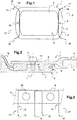
- L'invention et ses avantages apparaîtront avec plus de détails dans le cadre de la description qui suit avec des exemples donnés à titre illustratif en référence aux figures annexées qui représentent :
- la
figure 1 , une vue de face d'un assemblage vitré conforme à l'invention, - la
figure 2 , une vue en coupe partielle d'un assemblage vitré au niveau de l'interface entre un châssis et un panneau vitré, conformément à l'invention - les
figures 3 à 5 , des vues de face selon différents exemples de réalisation d'assemblages vitrés conformes à l'invention, - les
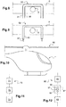
figures 6 à 7 , des vues en coupe partielle selon deux variantes d'assemblages vitrés, conformément à l'invention, - les
figures 8 à 9 , des vues de face selon d'autres exemples de réalisation d'assemblages vitrés conformes à l'invention, - la
figure 10 , une vue de côté d'un aéronef équipé d'un assemblage vitré, conformément à l'invention, - la
figure 11 , un premier logigramme illustrant les étapes du procédé de solidarisation conforme à l'invention, - la
figure 12 , un second logigramme illustrant les étapes du procédé de désolidarisation conforme à l'invention, et - les
figures 13 à 17 , des vues de face illustrant différentes variantes du procédé de désolidarisation conforme à l'invention. - Les éléments présents dans plusieurs figures distinctes peuvent être affectés d'une seule et même référence.
- Tel que représentée à la
figure 1 , l'invention concerne un assemblage 1 entre un châssis 2 comportant une bordure 3 au niveau de laquelle est rapporté un élément annexe 4 pouvant par exemple comporter une paroi 5 au moins partiellement transparent ou translucide. - En outre, un tel assemblage 1 est réalisé à l'aide d'un joint de colle 6 rapporté au niveau de la bordure 3 du châssis 2. Des excroissances 9, 10 peuvent notamment permettent de définir un écartement prédéterminé pour conférer au joint de colle 6 une épaisseur prédéterminée sur toute sa longueur.
- En effet telles que représentées à la
figure 2 , les excroissances 9, 10 forment des obstacles au découpage du joint de colle 6. Selon cet exemple de réalisation, les excroissances 9, 10 peuvent émerger d'une première face 7 du châssis 2 pour venir au contact d'une deuxième face 8 de l'élément annexe 4. De telles excroissances 9, 10 peuvent alors comporter par exemple des taraudages permettant de réaliser une liaison de type encastrement par vissage avec des moyens de solidarisation réversible 11 supplémentaires. - Selon d'autres variantes non représentées, les excroissances 9, 10 peuvent être formées par des tétons, des pions ou des bobines rapportées et s'étendant au moins partiellement entre la première face 7 du châssis 2 et la deuxième face 8 de l'élément annexe 4.
- Par ailleurs, un tel assemblage 1 comporte également des moyens d'aide au découpage 13 comportant un (ou des) organe(s) longiligne(s) 12 et/ou 14 noyé(s) au moins partiellement dans le joint de colle 6 et entourant l'une au moins des excroissances 9 et 10 en effectuant un changement d'orientation. Dans l'exemple de réalisation de la
figure 1 , un tel changement d'orientation permet de positionner les deux extrémités libres 15, 17 et 16, 18 d'un même côté 21 du joint de colle 6 agencé dans ce cas en regard d'une face extérieure du châssis 2. - Chaque organe longiligne 12 et 14 peut notamment comporter au moins un fil ou une gaine passe-fil permettant l'introduction d'un fil à l'intérieur du joint de colle 6.
- Tel que représenté à la
figure 2 , l'organe longiligne 12 est formé par un fil directement noyé dans le joint de colle 6 lors de son application sur le châssis 2. Un tel agencement permet ainsi de faciliter le découpage ultérieur du joint de colle 6 lorsque le l'élément annexe 4 doit être remplacé. Un effort de traction sur l'une au moins des extrémités libres 15 et 16 de l'organe longiligne 12 permet en effet de cisailler le joint de colle 6 par un rapprochement de l'organe longiligne 12 vers l'excroissance 10. - Tel que représenté à la
figure 3 , les moyens d'aide au découpage 13 comportent deux organes longilignes 12, 14 avantageusement formant deux demi-boucles se chevauchant partiellement. Une telle superposition des deux demi-boucles permet alors de découper en totalité une portion de joint de colle 6 agencée entre deux excroissances 9, 10 juxtaposées. - Selon cet exemple de réalisation de l'invention, les extrémités libres 15, 17 et 16, 18 des organes longilignes 12, 14 sont également agencées d'un même côté 21 du joint de colle 6.
- Cependant tels que représentés à la
figure 4 , les organes longilignes 22, 24, 32, 34 peuvent également former des boucles agencées autour des excroissances 9, 10, 19, 20 en réalisant un changement d'orientation de 360°. Dans ce cas, les extrémités libres 25, 27, 35, 37 et 26, 28, 36, 38 émergent alors des deux côtés opposés 29 et 30 par rapport à une direction d'application ou la direction longitudinale du joint de colle 6. - Tel que représenté à la
figure 5 , selon une autre variante de l'invention, un même organe longiligne 42 peut également former une première boucle 40 autour d'une première excroissance 9 et une deuxième boucle 41 autour d'une deuxième excroissance 10, les première et deuxième boucles 40 et 41 se chevauchant avantageusement. - Par ailleurs telles que représentées, les extrémités libres 45 et 46 de l'organe longiligne 42 sont agencées de part et d'autre du joint de colle 6 au niveau de deux côtés opposés 29 et 30.
- Tel que représenté à la
figure 6 selon une première variante d'assemblage, l'organe longiligne 12' peut être préalablement solidarisé avec la première face 7 du châssis 2. De cette manière, l'organe longiligne 12' reste précisément positionné par rapport au châssis 2 lors de l'application du joint de colle 6. - Par ailleurs tel que représenté à la
figure 7 selon une deuxième variante d'assemblage, l'organe longiligne 12" peut également être préalablement solidarisé avec la deuxième face 8 de l'élément annexe 4. De cette manière, le bon positionnement de l'organe longiligne 12" est garanti lors de l'assemblage entre le châssis 2 et l'élément annexe 4. - Tel que représenté à la
figure 8 selon un autre exemple d'assemblage, l'organe longiligne 52 peut comporter deux fils 50, 51 juxtaposés et permettant chacun de découper une épaisseur ou une largeur prédéterminée du joint de colle 6 autour d'une excroissance 9. Les deux fils 50, 51 peuvent alors être sollicités en traction simultanément ou encore successivement l'un après l'autre pour découper le joint de colle 6 autour de l'excroissance 9. - Selon un autre exemple d'assemblage tel que représenté à la
figure 9 , l'organe longiligne 62 comporte une gaine passe-fil 63 qui est apte à recevoir un fil 53. Ce fil 53 peut être mis en place simultanément avec la gaine passe-fil 63 lors de l'assemblage par collage dans le joint de colle 6 ou encore une fois le joint de colle 6 réalisé. De cette manière, le fil 53 est placé dans la gaine passe-fil 63 uniquement lorsqu'il est nécessaire de découper le joint de colle 6 autour de l'excroissance 9 pour procéder au remplacement de l'élément annexe 4. - Tel que représenté à la
figure 10 , l'invention concerne également un aéronef 60 en général, et un giravion en particulier, équipé d'un tel assemblage 1. Plus particulièrement, un tel assemblage 1 peut être formé par un assemblage vitré notamment entre un fuselage de giravion formant châssis et un parebrise avant de l'aéronef 60 formant l'élément annexe. - En outre, la
figure 11 est une représentation schématique du procédé de solidarisation 70 permettant de réaliser un assemblage 1 entre un châssis 2 et un élément annexe 4. Un tel précédé de solidarisation 70 comporte tout d'abord une étape préliminaire 71 consistant à positionner entre la première face 7 du châssis 2 et la deuxième face 8 de l'élément annexe 4 au moins un organe longilignes 12, 12', 12", 14, 22, 32, 42, 52, 62, 24, 34 tels que décrits auxfigures 1 à 9 au moins à proximité et autour d'au moins une excroissance 9, 10, 19, 20. - Le procédé 70 comporte ensuite une étape de collage 72 consistant à appliquer un joint de colle 6 à l'interface entre une première face 7 du châssis 2 et une deuxième face 8 de l'élément annexe 4. Tel que représenté, le procédé 70 peut également avantageusement comporter une étape de serrage 73 de moyens de solidarisation réversible 11 permettant de réaliser une liaison de type encastrement entre le châssis 2 et le l'élément annexe 4.
- Telle que représentée à la
figure 12 , l'invention se rapporte également à un procédé de désolidarisation 80 pouvant comporter une étape de desserrage 81 de moyens de solidarisation réversible 11 permettant de réaliser une liaison de type encastrement entre un châssis 2 et un élément annexe 4. - Un tel procédé de désolidarisation 80 comporte ensuite une étape d'insertion 82 consistant à insérer au moins un fil 84, 85, 87, 88, 184, 284 tel que représenté aux
figures 13 à 17 entre une première face 7 du châssis 2 et une deuxième face 8 de l'élément annexe 4. En outre, un tel fil 84, 85, 87, 88, 184, 284 peut être inséré au moins à proximité et autour d'au moins une excroissance 9, 10, au niveau d'une forme concave 109 d'une bordure 3 du châssis 2 et/ou encore au niveau d'une surface gauche 209 de la bordure 3 du châssis 2. - En outre tel que représenté à la
figure 14 , une telle étape d'insertion 82 peut avantageusement comporter au moins une première sous étape de passage 90 du fil 87 au travers du joint de colle 6 suivant une première direction transversale d1, au moins une deuxième sous étape de passage 91 du fil 87 au travers du joint de colle 6 suivant une seconde direction transversale d2 opposée à la première direction transversale d1 et au moins une troisième sous étape de passage 91 du fil 87 au travers du joint de colle 6 suivant la première direction transversale d1. Ces première et seconde directions transversales d1 et d2 sont par ailleurs orientées sensiblement perpendiculairement par rapport à une direction longitudinale D du joint de colle 6. - Par ailleurs, la troisième sous étape de passage 92 est effectuée en amont de ladite deuxième sous étape de passage 91 suivant la direction longitudinale D dudit joint de colle 6.
- Le procédé de désolidarisation 80 comporte également une étape de découpage 83 du joint de colle 6 réalisée en exerçant un effort de traction sur l'une au moins des extrémités libres du fil 84, 85, 87, 88, 184, 284.
- Tel que représenté à la
figure 13 , les fils 84, 85 entourent respectivement une excroissance 9, 10 en formant respectivement chacun une boucle 86. Chaque boucle 86 se superpose avec les deux boucles adjacentes de manière à permettre un découpage total du joint de colle 6 agencé entre deux excroissances 9, 10 adjacentes. - La
figure 14 illustre quant à elle un unique fil 87 formant une première boucle 96 autour une première excroissance 9 et une seconde boucle 97 entourant quant à elle une deuxième excroissance 10. - La
figure 15 représente quant à elle le découpage d'un joint de colle 6 au niveau d'une forme concave 109 d'une bordure 3 du châssis 2. Un tel découpage est alors réalisé au moyen d'un fil 184 inséré au travers du joint de colle 6 en effectuant une boucle 186 au niveau de la forme concave 109. Une telle étape d'insertion 82 du fil 184 permet ainsi d'éviter toute sortie accidentelle du fil 184 lors de l'effort de traction permettant de découper le joint de colle 6. - Les extrémités libres du fil 184 émergent de part et d'autre du joint de colle 6 et par conséquent le fil 184 effectue un changement d'orientation de 360° en passant trois fois au travers du joint de colle 6.
- De même et tel que représenté à la
figure 16 , le découpage d'un joint de colle 6 peut également être réalisé au niveau d'une surface gauche 209 d'une bordure 3 du châssis 2. Une telle surface gauche 209 est ainsi formée par une zone non plane comportant un galbe prononcé par rapport au reste de la bordure 3 du châssis 2. - Dans ce cas, l'étape d'insertion 82 est alors réalisée au moyen d'un fil 284 inséré au travers du joint de colle 6 en effectuant une boucle 286 au niveau de la surface gauche 209.
- Telles que représentées, les extrémités libres du fil 284 émergent d'un même côté du joint de colle 6 et le fil 284 effectue un changement d'orientation de 540° en passant quatre fois au travers du joint de colle 6.
- Tel que représenté à la
figure 17 , l'étape de découpage 83 peut être réalisée en utilisant un organe enrouleur 100 exerçant un effort de traction sur une première extrémité libre 89 du fil 88, une seconde extrémité libre 99 du fil 88 étant quant à elle solidarisée avec un point fixe de l'organe enrouleur 100 par rapport à l'élément annexe 4. Un tel organe enrouleur 100 est alors solidarisé de manière réversible avec l'élément annexe 4 et permet, via une manivelle 101 de resserrer les deux boucles 96, 97 formées par le fil 88 autour des deux excroissances 9, 10. - Un tel organe enrouleur 100 comporte des moyens de démultiplication permettant ainsi de réduire l'effort de traction nécessaire pour réaliser un découpage manuel par un opérateur.
- Naturellement, la présente invention est sujette à de nombreuses variations quant à sa mise en oeuvre. Bien que plusieurs modes de réalisation aient été décrits, on comprend bien qu'il n'est pas concevable d'identifier de manière exhaustive tous les modes possibles. Il est bien sûr envisageable de remplacer un moyen décrit par un moyen équivalent sans sortir du cadre de la présente invention.
Claims (16)
- Assemblage (1) comportant un châssis (2) muni d'une bordure (3), un élément annexe (4) rapporté au niveau de ladite bordure (3) dudit châssis (2), un joint de colle (6) agencé à l'interface entre une première face (7) dudit châssis (2) et une deuxième face (8) dudit élément annexe (4) et au moins une excroissance (9, 10, 19, 20) agencée dans ledit joint de colle (6) et formant au moins un obstacle au découpage dudit joint de colle (6), ladite au moins une excroissance (9, 10, 19, 20) s'étendant au moins partiellement entre ladite première face (7) dudit châssis (2) et ladite seconde face (8) dudit élément annexe (4),
ledit assemblage (1) comportant des moyens d'aide au découpage (13) dudit joint de colle (6), lesdits moyens d'aide au découpage (13) comportant au moins un organe longiligne (12, 12', 12", 22, 32, 42, 52, 62, 14, 24, 34) partiellement noyé à l'intérieur dudit joint de colle (6),
caractérisé en ce que ledit au moins un organe longiligne (12, 12', 12", 22, 32, 42, 52, 62, 14, 24, 34) est agencé au moins à proximité et autour de ladite au moins une excroissance (9, 10, 19, 20) et en ce que ledit au moins un organe longiligne (12, 12', 12", 22, 32, 42, 52, 62, 14, 24, 34) comporte deux extrémités libres (15, 17, 25, 27, 35, 37, 45) et (16, 18,26, 28, 36, 38, 46) émergeant dudit joint de colle (6). - Assemblage selon la revendication 1,
caractérisé en ce que ledit au moins un organe longiligne (12, 14) comporte deux extrémités libres (15, 17) et (16, 18) émergeant dudit joint de colle (6) d'un même côté (21) par rapport audit joint de colle (6). - Assemblage selon la revendication 1,
caractérisé en ce que ledit au moins un organe longiligne (22, 24, 32, 34, 42) comporte deux extrémités libres (25, 27, 35, 37, 45) et (26, 28, 36, 38, 46) émergeant dudit joint de colle (6) des deux côtés opposés (29) et (30) par rapport audit joint de colle (6). - Assemblage selon l'une quelconque des revendications 1 à 3,
caractérisé en ce que ledit au moins un organe longiligne (52, 62) comporte au moins un fil (50, 51, 53). - Assemblage selon l'une quelconque des revendications 1 à 4,
caractérisé en ce que ledit au moins un organe longiligne (62) comporte au moins une gaine passe-fil (63) destinée à recevoir au moins un fil (53). - Assemblage selon l'une quelconque des revendications 1 à 5,
caractérisé en ce que ledit au moins un organe longiligne (12') est préalablement solidarisé avec ladite première face (7) dudit châssis (2). - Assemblage selon l'une quelconque des revendications 1 à 5,
caractérisé en ce que ledit au moins un organe longiligne (12") est préalablement solidarisé avec ladite deuxième face (8) dudit élément annexe (4). - Assemblage selon l'une quelconque des revendications 1 à 7,
caractérisé en ce que ledit au moins un organe longiligne (12, 14, 22, 24, 32, 34) forme au moins une demi-boucle autour de ladite au moins une excroissance (9, 10, 19, 20). - Assemblage selon l'une quelconque des revendications 1 à 8,
caractérisé en ce que ledit au moins un organe longiligne (42) forme au moins une première boucle (40) autour d'une première excroissance (9) et au moins une deuxième boucle (41) autour d'une deuxième excroissance (10). - Aéronef (60) caractérisé en ce qu'il comporte au moins un assemblage (1) selon l'une quelconque des revendications 1 à 9.
- Procédé de solidarisation (70) entre un châssis (2) et au moins un élément annexe (4) rapporté au niveau d'une bordure (3) dudit châssis (2), ledit procédé de solidarisation (70) comportant une étape de collage (72) consistant à appliquer un joint de colle (6) à l'interface entre une première face (7) dudit châssis (2) et une deuxième face (8) dudit élément annexe (4),
caractérisé en ce que ledit procédé de solidarisation (70) permet de réaliser un assemblage (1) selon l'une quelconque des revendications 1 à 9, ledit procédé de solidarisation (70) comportant une étape préliminaire (71) consistant à positionner entre ladite première face (7) dudit châssis (2) et ladite deuxième face (8) dudit élément annexe (4) ledit au moins un organe longiligne (12, 12', 12", 14, 22, 32, 42, 52, 62, 24, 34) au moins à proximité et autour de ladite au moins une excroissance (9, 10, 19, 20), ledit au moins un organe longiligne (12, 12', 12", 22, 32, 42, 52, 62, 14, 24, 34) étant ensuite partiellement noyé à l'intérieur dudit joint de colle (6) lors de ladite étape de collage (72). - Procédé de désolidarisation (80) entre un châssis (2) et un élément annexe (4) rapporté au niveau d'une bordure (3) dudit châssis (2), ledit élément annexe (4) étant solidarisé audit châssis (2) au moins par collage via un joint de colle (6) agencé à l'interface entre une première face (7) dudit châssis (2) et une deuxième face (8) dudit élément annexe (4), ledit procédé de désolidarisation (80) comportant :• une étape d'insertion (82) consistant à insérer au moins un fil (84, 85, 87, 88, 184, 284) au travers dudit au moins un joint de colle (6) entre ladite première face (7) dudit châssis (2) et ladite deuxième face (8) dudit élément annexe (4), et• une étape de découpage (83) dudit joint de colle (6) en exerçant un effort de traction sur au moins une extrémité dudit au moins un fil (84, 85, 87, 88, 184, 284),caractérisé en ce que ladite étape d'insertion (82) comporte au moins trois sous étapes de passage (90), (91) et (92) dudit au moins un fil (84, 85, 87, 88, 184, 284) transversalement au travers dudit joint de colle (6), lesdites au moins trois sous étapes de passage (90), (91) et (92) comportant d'une part une première sous étape de passage (90) et une troisième sous étape de passage (92) entre un premier côté (29) et un second côté (30) dudit joint de colle (6) et d'autre part une deuxième sous étape de passage (91) entre ledit second côté (30) et ledit premier côté (29) dudit joint de colle (6), ladite troisième sous étape de passage (92) étant effectuée en amont ladite deuxième sous étape de passage (91) suivant une direction longitudinale D dudit joint de colle (6).
- Procédé selon la revendication 12,
caractérisé en ce que, au moins une excroissance (9, 10, 19, 20) étant agencée dans ledit joint de colle (6) et formant au moins un obstacle au découpage dudit joint de colle (6), ladite au moins une excroissance (9, 10, 19, 20) s'étendant au moins partiellement entre ladite première face (7) dudit châssis (2) et ladite seconde face (8) dudit élément annexe (4), lesdites au moins trois sous étapes de passage (90), (91) et (92) de ladite étape d'insertion (82) sont réalisées localement au travers dudit joint de colle (6) à proximité et autour de ladite au moins une excroissance (9, 10, 19, 20), ledit au moins un fil (84, 85, 87, 88) formant au moins une boucle (86, 96, 97) autour de ladite au moins une excroissance (9, 10, 19, 20). - Procédé selon l'une quelconque des revendications 12 à 13,
caractérisé en ce que lesdites au moins trois sous étapes de passage (90), (91) et (92) de ladite étape d'insertion (82) sont réalisées localement au travers dudit joint de colle (6) au niveau d'une forme concave (109) de ladite bordure (3) dudit châssis (2), ledit au moins un fil (184) formant au moins une boucle (186) au niveau de ladite forme concave (109) de ladite bordure (3). - Procédé selon l'une quelconque des revendications 12 à 14,
caractérisé en ce que lesdites au moins trois sous étapes de passage (90), (91) et (92) de ladite étape d'insertion (82) sont réalisées localement au travers dudit joint de colle (6) au niveau d'une surface gauche (209) de ladite bordure (3) dudit châssis (2), ledit au moins un fil (284) formant au moins une boucle (286) au niveau de ladite surface gauche (209) de ladite bordure (3). - Procédé selon l'une quelconque des revendications 12 à 15,
caractérisé en ce que ladite étape de découpage (83) est réalisée en exerçant un effort de traction sur au moins une extrémité libre (89) dudit au moins un fil (88, 184, 284) au moyen d'un organe enrouleur (100) permettant d'enrouler ledit au moins un fil (88, 184, 284), ledit effort de traction permettant de resserrer ladite au moins une boucle (96, 97, 186, 286) dudit au moins un fil (88, 184, 284).
Applications Claiming Priority (1)
| Application Number | Priority Date | Filing Date | Title |
|---|---|---|---|
| FR1770695A FR3068404B1 (fr) | 2017-06-30 | 2017-06-30 | Assemblage entre un chassis et un element annexe,aeronef comportant un tel assemblage et procedes de solidarisation et de desolidarisation d'un tel assemblage |
Publications (2)
| Publication Number | Publication Date |
|---|---|
| EP3421350A1 true EP3421350A1 (fr) | 2019-01-02 |
| EP3421350B1 EP3421350B1 (fr) | 2020-10-07 |
Family
ID=59859394
Family Applications (1)
| Application Number | Title | Priority Date | Filing Date |
|---|---|---|---|
| EP18170490.9A Active EP3421350B1 (fr) | 2017-06-30 | 2018-05-03 | Assemblage entre un chassis et un element annexe, aeronef comportant un tel assemblage et procedes de solidarisation et de desolidarisation d'un tel assemblage |
Country Status (2)
| Country | Link |
|---|---|
| EP (1) | EP3421350B1 (fr) |
| FR (1) | FR3068404B1 (fr) |
Cited By (1)
| Publication number | Priority date | Publication date | Assignee | Title |
|---|---|---|---|---|
| CN114056540A (zh) * | 2021-10-26 | 2022-02-18 | 航天特种材料及工艺技术研究所 | 一种舱门热密封材料构件及其制备方法 |
Families Citing this family (1)
| Publication number | Priority date | Publication date | Assignee | Title |
|---|---|---|---|---|
| FR3121483B1 (fr) | 2021-03-30 | 2023-02-24 | Airbus Helicopters | Assemblage ayant deux éléments assemblés par un joint de colle muni de tunnels obturés, véhicule comportant un tel assemblage et procédés de solidarisation et de désolidarisation d’un tel assemblage |
Citations (5)
| Publication number | Priority date | Publication date | Assignee | Title |
|---|---|---|---|---|
| EP0298788A2 (fr) * | 1987-07-09 | 1989-01-11 | Saint-Gobain Vitrage International | Méthode de pose de vitrage automobile par collage direct et vitrage pour le collage |
| DE19621577A1 (de) * | 1996-04-02 | 1997-12-04 | Walter Naesl | Verfahren und Vorrichtung zur Montage und Demontage eines verklebten Elementes |
| FR2766156A1 (fr) * | 1997-07-18 | 1999-01-22 | Eurocopter France | Encadrement de vitre permettant le largage d'un hublot d'helicoptere |
| US20050200163A1 (en) * | 2004-03-09 | 2005-09-15 | Arnold Edward H.Jr. | Motor vehicle fixed window removal system |
| EP2610097A1 (fr) * | 2011-12-27 | 2013-07-03 | Eurocopter | Dispositif de fixation réversible d'un panneau à une structure pour obturer une fenêtre de cette structure, véhicule et procédé |
-
2017
- 2017-06-30 FR FR1770695A patent/FR3068404B1/fr not_active Expired - Fee Related
-
2018
- 2018-05-03 EP EP18170490.9A patent/EP3421350B1/fr active Active
Patent Citations (5)
| Publication number | Priority date | Publication date | Assignee | Title |
|---|---|---|---|---|
| EP0298788A2 (fr) * | 1987-07-09 | 1989-01-11 | Saint-Gobain Vitrage International | Méthode de pose de vitrage automobile par collage direct et vitrage pour le collage |
| DE19621577A1 (de) * | 1996-04-02 | 1997-12-04 | Walter Naesl | Verfahren und Vorrichtung zur Montage und Demontage eines verklebten Elementes |
| FR2766156A1 (fr) * | 1997-07-18 | 1999-01-22 | Eurocopter France | Encadrement de vitre permettant le largage d'un hublot d'helicoptere |
| US20050200163A1 (en) * | 2004-03-09 | 2005-09-15 | Arnold Edward H.Jr. | Motor vehicle fixed window removal system |
| EP2610097A1 (fr) * | 2011-12-27 | 2013-07-03 | Eurocopter | Dispositif de fixation réversible d'un panneau à une structure pour obturer une fenêtre de cette structure, véhicule et procédé |
Cited By (2)
| Publication number | Priority date | Publication date | Assignee | Title |
|---|---|---|---|---|
| CN114056540A (zh) * | 2021-10-26 | 2022-02-18 | 航天特种材料及工艺技术研究所 | 一种舱门热密封材料构件及其制备方法 |
| CN114056540B (zh) * | 2021-10-26 | 2023-05-05 | 航天特种材料及工艺技术研究所 | 一种舱门热密封材料构件及其制备方法 |
Also Published As
| Publication number | Publication date |
|---|---|
| FR3068404A1 (fr) | 2019-01-04 |
| FR3068404B1 (fr) | 2020-05-22 |
| EP3421350B1 (fr) | 2020-10-07 |
Similar Documents
| Publication | Publication Date | Title |
|---|---|---|
| CA2882819C (fr) | Systeme de joint pour vitrage de vehicule, vitrage equipe du systeme et procede de montage du vitrage | |
| EP2483057B1 (fr) | Procede de fixation d'une piece rapportee sur un cordon profile et vitrage obtenu par le procede | |
| CA1327620C (fr) | Methode de pose de vitrage automobile par collage direct et vitrage pour le collage | |
| EP3209484B1 (fr) | Assemblage par un element d'ancrage mecanique entre deux pieces dont l'une est realisee en materiau composite | |
| FR2927675A1 (fr) | Dispositif de fixation provisoire et reutilisable destine au pre-assemblage d'au moins deux elements structuraux prealablement perces. | |
| EP3421350B1 (fr) | Assemblage entre un chassis et un element annexe, aeronef comportant un tel assemblage et procedes de solidarisation et de desolidarisation d'un tel assemblage | |
| FR2917666A1 (fr) | Roue a rayon demontable en materiau composite | |
| EP2159154A1 (fr) | Encadrement étanche d'un hublot | |
| EP3670274A1 (fr) | Piece de carrosserie comprenant une boucle de verrouillage | |
| EP4158221B1 (fr) | Dispositif de jonction de bande transporteuse a câbles muni d'elements de blocage de câble | |
| FR2863185A1 (fr) | Dispositif d'equipement d'un trou dans un panneau et panneau ainsi equipe | |
| EP2610097B1 (fr) | Dispositif de fixation réversible d'un panneau à une structure pour obturer une fenêtre de cette structure, véhicule et procédé | |
| EP3334578B1 (fr) | Procédé de fabrication d'un cadre de forme annulaire | |
| EP4067674B1 (fr) | Assemblage ayant deux elements assembles par un joint de colle muni de tunnels obtures, vehicule comportant un tel assemblage et procedes de solidarisation et de desolidarisation d'un tel assemblage | |
| FR3025452B1 (fr) | Piece composite renforcee de fibres et procede pour fabriquer une piece composite renforcee de fibres | |
| EP3751154B1 (fr) | Insert fileté pour panneau sandwich, procédé d'assemblage et assemblage correspondant | |
| FR3101327A1 (fr) | Système de fixation d’un equipement sur une poutre d’aeronef, comprenant deux dispositifs d’enserrage destines a etre forces l’un en direction de l’autre | |
| EP2412888A2 (fr) | Connecteur de raccordement d'une plaque isolante et d'au moins une paroi d'un mur à isolation intégrée, élément de construction comportant un tel connecteur et mur comportant un tel élément de construction | |
| EP3724523B1 (fr) | Dispositif de fixation, ensemble de fixation comprenant un tel dispositif et procede de fabrication d'un tel ensemble | |
| EP2075525B1 (fr) | Cordeau de découpe pyrotechnique et procédé de fabrication d'un tel cordeau | |
| EP2620659B1 (fr) | Accessoire d'assemblage d'un matériel à une structure composite, ensemble pour doter une structure composite d'un tel accessoire et procédé de fixation d'un tel accessoire | |
| OA21151A (fr) | Dispositif de jonction de bande transporteuse à cables muni d'éléments de blocage de cable | |
| EP4688403A1 (fr) | Assemblage comportant au moins une piece composite et des moyens de fixation | |
| WO2009066027A1 (fr) | Procede de montage d'un embout sur une conduite pour former un raccord | |
| WO2015090987A1 (fr) | Traverse pour planche de bord avec support latéral a structure mixte métallo-plastique |
Legal Events
| Date | Code | Title | Description |
|---|---|---|---|
| PUAI | Public reference made under article 153(3) epc to a published international application that has entered the european phase |
Free format text: ORIGINAL CODE: 0009012 |
|
| STAA | Information on the status of an ep patent application or granted ep patent |
Free format text: STATUS: THE APPLICATION HAS BEEN PUBLISHED |
|
| AK | Designated contracting states |
Kind code of ref document: A1 Designated state(s): AL AT BE BG CH CY CZ DE DK EE ES FI FR GB GR HR HU IE IS IT LI LT LU LV MC MK MT NL NO PL PT RO RS SE SI SK SM TR |
|
| AX | Request for extension of the european patent |
Extension state: BA ME |
|
| STAA | Information on the status of an ep patent application or granted ep patent |
Free format text: STATUS: REQUEST FOR EXAMINATION WAS MADE |
|
| 17P | Request for examination filed |
Effective date: 20181220 |
|
| RBV | Designated contracting states (corrected) |
Designated state(s): AL AT BE BG CH CY CZ DE DK EE ES FI FR GB GR HR HU IE IS IT LI LT LU LV MC MK MT NL NO PL PT RO RS SE SI SK SM TR |
|
| GRAP | Despatch of communication of intention to grant a patent |
Free format text: ORIGINAL CODE: EPIDOSNIGR1 |
|
| STAA | Information on the status of an ep patent application or granted ep patent |
Free format text: STATUS: GRANT OF PATENT IS INTENDED |
|
| RIC1 | Information provided on ipc code assigned before grant |
Ipc: B64C 1/14 20060101AFI20200507BHEP Ipc: F16B 11/00 20060101ALN20200507BHEP Ipc: B60J 10/70 20160101ALI20200507BHEP |
|
| INTG | Intention to grant announced |
Effective date: 20200529 |
|
| GRAS | Grant fee paid |
Free format text: ORIGINAL CODE: EPIDOSNIGR3 |
|
| GRAA | (expected) grant |
Free format text: ORIGINAL CODE: 0009210 |
|
| STAA | Information on the status of an ep patent application or granted ep patent |
Free format text: STATUS: THE PATENT HAS BEEN GRANTED |
|
| AK | Designated contracting states |
Kind code of ref document: B1 Designated state(s): AL AT BE BG CH CY CZ DE DK EE ES FI FR GB GR HR HU IE IS IT LI LT LU LV MC MK MT NL NO PL PT RO RS SE SI SK SM TR |
|
| REG | Reference to a national code |
Ref country code: GB Ref legal event code: FG4D Free format text: NOT ENGLISH |
|
| REG | Reference to a national code |
Ref country code: CH Ref legal event code: EP Ref country code: AT Ref legal event code: REF Ref document number: 1320925 Country of ref document: AT Kind code of ref document: T Effective date: 20201015 |
|
| REG | Reference to a national code |
Ref country code: IE Ref legal event code: FG4D Free format text: LANGUAGE OF EP DOCUMENT: FRENCH |
|
| REG | Reference to a national code |
Ref country code: DE Ref legal event code: R096 Ref document number: 602018008395 Country of ref document: DE |
|
| REG | Reference to a national code |
Ref country code: NL Ref legal event code: MP Effective date: 20201007 |
|
| REG | Reference to a national code |
Ref country code: AT Ref legal event code: MK05 Ref document number: 1320925 Country of ref document: AT Kind code of ref document: T Effective date: 20201007 |
|
| PG25 | Lapsed in a contracting state [announced via postgrant information from national office to epo] |
Ref country code: GR Free format text: LAPSE BECAUSE OF FAILURE TO SUBMIT A TRANSLATION OF THE DESCRIPTION OR TO PAY THE FEE WITHIN THE PRESCRIBED TIME-LIMIT Effective date: 20210108 Ref country code: NO Free format text: LAPSE BECAUSE OF FAILURE TO SUBMIT A TRANSLATION OF THE DESCRIPTION OR TO PAY THE FEE WITHIN THE PRESCRIBED TIME-LIMIT Effective date: 20210107 Ref country code: FI Free format text: LAPSE BECAUSE OF FAILURE TO SUBMIT A TRANSLATION OF THE DESCRIPTION OR TO PAY THE FEE WITHIN THE PRESCRIBED TIME-LIMIT Effective date: 20201007 Ref country code: PT Free format text: LAPSE BECAUSE OF FAILURE TO SUBMIT A TRANSLATION OF THE DESCRIPTION OR TO PAY THE FEE WITHIN THE PRESCRIBED TIME-LIMIT Effective date: 20210208 Ref country code: RS Free format text: LAPSE BECAUSE OF FAILURE TO SUBMIT A TRANSLATION OF THE DESCRIPTION OR TO PAY THE FEE WITHIN THE PRESCRIBED TIME-LIMIT Effective date: 20201007 |
|
| REG | Reference to a national code |
Ref country code: LT Ref legal event code: MG4D |
|
| PG25 | Lapsed in a contracting state [announced via postgrant information from national office to epo] |
Ref country code: AT Free format text: LAPSE BECAUSE OF FAILURE TO SUBMIT A TRANSLATION OF THE DESCRIPTION OR TO PAY THE FEE WITHIN THE PRESCRIBED TIME-LIMIT Effective date: 20201007 Ref country code: ES Free format text: LAPSE BECAUSE OF FAILURE TO SUBMIT A TRANSLATION OF THE DESCRIPTION OR TO PAY THE FEE WITHIN THE PRESCRIBED TIME-LIMIT Effective date: 20201007 Ref country code: BG Free format text: LAPSE BECAUSE OF FAILURE TO SUBMIT A TRANSLATION OF THE DESCRIPTION OR TO PAY THE FEE WITHIN THE PRESCRIBED TIME-LIMIT Effective date: 20210107 Ref country code: LV Free format text: LAPSE BECAUSE OF FAILURE TO SUBMIT A TRANSLATION OF THE DESCRIPTION OR TO PAY THE FEE WITHIN THE PRESCRIBED TIME-LIMIT Effective date: 20201007 Ref country code: IS Free format text: LAPSE BECAUSE OF FAILURE TO SUBMIT A TRANSLATION OF THE DESCRIPTION OR TO PAY THE FEE WITHIN THE PRESCRIBED TIME-LIMIT Effective date: 20210207 Ref country code: PL Free format text: LAPSE BECAUSE OF FAILURE TO SUBMIT A TRANSLATION OF THE DESCRIPTION OR TO PAY THE FEE WITHIN THE PRESCRIBED TIME-LIMIT Effective date: 20201007 Ref country code: SE Free format text: LAPSE BECAUSE OF FAILURE TO SUBMIT A TRANSLATION OF THE DESCRIPTION OR TO PAY THE FEE WITHIN THE PRESCRIBED TIME-LIMIT Effective date: 20201007 |
|
| PG25 | Lapsed in a contracting state [announced via postgrant information from national office to epo] |
Ref country code: HR Free format text: LAPSE BECAUSE OF FAILURE TO SUBMIT A TRANSLATION OF THE DESCRIPTION OR TO PAY THE FEE WITHIN THE PRESCRIBED TIME-LIMIT Effective date: 20201007 Ref country code: NL Free format text: LAPSE BECAUSE OF FAILURE TO SUBMIT A TRANSLATION OF THE DESCRIPTION OR TO PAY THE FEE WITHIN THE PRESCRIBED TIME-LIMIT Effective date: 20201007 |
|
| REG | Reference to a national code |
Ref country code: DE Ref legal event code: R097 Ref document number: 602018008395 Country of ref document: DE |
|
| PG25 | Lapsed in a contracting state [announced via postgrant information from national office to epo] |
Ref country code: RO Free format text: LAPSE BECAUSE OF FAILURE TO SUBMIT A TRANSLATION OF THE DESCRIPTION OR TO PAY THE FEE WITHIN THE PRESCRIBED TIME-LIMIT Effective date: 20201007 Ref country code: SK Free format text: LAPSE BECAUSE OF FAILURE TO SUBMIT A TRANSLATION OF THE DESCRIPTION OR TO PAY THE FEE WITHIN THE PRESCRIBED TIME-LIMIT Effective date: 20201007 Ref country code: LT Free format text: LAPSE BECAUSE OF FAILURE TO SUBMIT A TRANSLATION OF THE DESCRIPTION OR TO PAY THE FEE WITHIN THE PRESCRIBED TIME-LIMIT Effective date: 20201007 Ref country code: CZ Free format text: LAPSE BECAUSE OF FAILURE TO SUBMIT A TRANSLATION OF THE DESCRIPTION OR TO PAY THE FEE WITHIN THE PRESCRIBED TIME-LIMIT Effective date: 20201007 Ref country code: EE Free format text: LAPSE BECAUSE OF FAILURE TO SUBMIT A TRANSLATION OF THE DESCRIPTION OR TO PAY THE FEE WITHIN THE PRESCRIBED TIME-LIMIT Effective date: 20201007 Ref country code: SM Free format text: LAPSE BECAUSE OF FAILURE TO SUBMIT A TRANSLATION OF THE DESCRIPTION OR TO PAY THE FEE WITHIN THE PRESCRIBED TIME-LIMIT Effective date: 20201007 |
|
| PLBE | No opposition filed within time limit |
Free format text: ORIGINAL CODE: 0009261 |
|
| STAA | Information on the status of an ep patent application or granted ep patent |
Free format text: STATUS: NO OPPOSITION FILED WITHIN TIME LIMIT |
|
| PG25 | Lapsed in a contracting state [announced via postgrant information from national office to epo] |
Ref country code: DK Free format text: LAPSE BECAUSE OF FAILURE TO SUBMIT A TRANSLATION OF THE DESCRIPTION OR TO PAY THE FEE WITHIN THE PRESCRIBED TIME-LIMIT Effective date: 20201007 |
|
| 26N | No opposition filed |
Effective date: 20210708 |
|
| PG25 | Lapsed in a contracting state [announced via postgrant information from national office to epo] |
Ref country code: AL Free format text: LAPSE BECAUSE OF FAILURE TO SUBMIT A TRANSLATION OF THE DESCRIPTION OR TO PAY THE FEE WITHIN THE PRESCRIBED TIME-LIMIT Effective date: 20201007 |
|
| PG25 | Lapsed in a contracting state [announced via postgrant information from national office to epo] |
Ref country code: SI Free format text: LAPSE BECAUSE OF FAILURE TO SUBMIT A TRANSLATION OF THE DESCRIPTION OR TO PAY THE FEE WITHIN THE PRESCRIBED TIME-LIMIT Effective date: 20201007 |
|
| REG | Reference to a national code |
Ref country code: DE Ref legal event code: R119 Ref document number: 602018008395 Country of ref document: DE |
|
| REG | Reference to a national code |
Ref country code: CH Ref legal event code: PL |
|
| PG25 | Lapsed in a contracting state [announced via postgrant information from national office to epo] |
Ref country code: CH Free format text: LAPSE BECAUSE OF NON-PAYMENT OF DUE FEES Effective date: 20210531 Ref country code: MC Free format text: LAPSE BECAUSE OF FAILURE TO SUBMIT A TRANSLATION OF THE DESCRIPTION OR TO PAY THE FEE WITHIN THE PRESCRIBED TIME-LIMIT Effective date: 20201007 Ref country code: LU Free format text: LAPSE BECAUSE OF NON-PAYMENT OF DUE FEES Effective date: 20210503 Ref country code: LI Free format text: LAPSE BECAUSE OF NON-PAYMENT OF DUE FEES Effective date: 20210531 |
|
| REG | Reference to a national code |
Ref country code: BE Ref legal event code: MM Effective date: 20210531 |
|
| PG25 | Lapsed in a contracting state [announced via postgrant information from national office to epo] |
Ref country code: IE Free format text: LAPSE BECAUSE OF NON-PAYMENT OF DUE FEES Effective date: 20210503 Ref country code: DE Free format text: LAPSE BECAUSE OF NON-PAYMENT OF DUE FEES Effective date: 20211201 |
|
| PG25 | Lapsed in a contracting state [announced via postgrant information from national office to epo] |
Ref country code: IS Free format text: LAPSE BECAUSE OF FAILURE TO SUBMIT A TRANSLATION OF THE DESCRIPTION OR TO PAY THE FEE WITHIN THE PRESCRIBED TIME-LIMIT Effective date: 20210207 |
|
| PG25 | Lapsed in a contracting state [announced via postgrant information from national office to epo] |
Ref country code: BE Free format text: LAPSE BECAUSE OF NON-PAYMENT OF DUE FEES Effective date: 20210531 |
|
| PG25 | Lapsed in a contracting state [announced via postgrant information from national office to epo] |
Ref country code: CY Free format text: LAPSE BECAUSE OF FAILURE TO SUBMIT A TRANSLATION OF THE DESCRIPTION OR TO PAY THE FEE WITHIN THE PRESCRIBED TIME-LIMIT Effective date: 20201007 |
|
| P01 | Opt-out of the competence of the unified patent court (upc) registered |
Effective date: 20230530 |
|
| PG25 | Lapsed in a contracting state [announced via postgrant information from national office to epo] |
Ref country code: HU Free format text: LAPSE BECAUSE OF FAILURE TO SUBMIT A TRANSLATION OF THE DESCRIPTION OR TO PAY THE FEE WITHIN THE PRESCRIBED TIME-LIMIT; INVALID AB INITIO Effective date: 20180503 |
|
| PG25 | Lapsed in a contracting state [announced via postgrant information from national office to epo] |
Ref country code: MK Free format text: LAPSE BECAUSE OF FAILURE TO SUBMIT A TRANSLATION OF THE DESCRIPTION OR TO PAY THE FEE WITHIN THE PRESCRIBED TIME-LIMIT Effective date: 20201007 |
|
| PG25 | Lapsed in a contracting state [announced via postgrant information from national office to epo] |
Ref country code: MT Free format text: LAPSE BECAUSE OF FAILURE TO SUBMIT A TRANSLATION OF THE DESCRIPTION OR TO PAY THE FEE WITHIN THE PRESCRIBED TIME-LIMIT Effective date: 20201007 |
|
| PGFP | Annual fee paid to national office [announced via postgrant information from national office to epo] |
Ref country code: GB Payment date: 20250527 Year of fee payment: 8 |
|
| PGFP | Annual fee paid to national office [announced via postgrant information from national office to epo] |
Ref country code: IT Payment date: 20250527 Year of fee payment: 8 |
|
| PGFP | Annual fee paid to national office [announced via postgrant information from national office to epo] |
Ref country code: FR Payment date: 20250528 Year of fee payment: 8 |
|
| PG25 | Lapsed in a contracting state [announced via postgrant information from national office to epo] |
Ref country code: TR Free format text: LAPSE BECAUSE OF FAILURE TO SUBMIT A TRANSLATION OF THE DESCRIPTION OR TO PAY THE FEE WITHIN THE PRESCRIBED TIME-LIMIT Effective date: 20201007 |