EP3421310A1 - A brake pedal latching with electric status indication signal - Google Patents
A brake pedal latching with electric status indication signal Download PDFInfo
- Publication number
- EP3421310A1 EP3421310A1 EP17179142.9A EP17179142A EP3421310A1 EP 3421310 A1 EP3421310 A1 EP 3421310A1 EP 17179142 A EP17179142 A EP 17179142A EP 3421310 A1 EP3421310 A1 EP 3421310A1
- Authority
- EP
- European Patent Office
- Prior art keywords
- brake pedal
- braking system
- linking mechanism
- pin
- handle
- Prior art date
- Legal status (The legal status is an assumption and is not a legal conclusion. Google has not performed a legal analysis and makes no representation as to the accuracy of the status listed.)
- Granted
Links
Images



Classifications
-
- B—PERFORMING OPERATIONS; TRANSPORTING
- B60—VEHICLES IN GENERAL
- B60T—VEHICLE BRAKE CONTROL SYSTEMS OR PARTS THEREOF; BRAKE CONTROL SYSTEMS OR PARTS THEREOF, IN GENERAL; ARRANGEMENT OF BRAKING ELEMENTS ON VEHICLES IN GENERAL; PORTABLE DEVICES FOR PREVENTING UNWANTED MOVEMENT OF VEHICLES; VEHICLE MODIFICATIONS TO FACILITATE COOLING OF BRAKES
- B60T7/00—Brake-action initiating means
- B60T7/02—Brake-action initiating means for personal initiation
- B60T7/04—Brake-action initiating means for personal initiation foot actuated
- B60T7/06—Disposition of pedal
-
- B—PERFORMING OPERATIONS; TRANSPORTING
- B60—VEHICLES IN GENERAL
- B60T—VEHICLE BRAKE CONTROL SYSTEMS OR PARTS THEREOF; BRAKE CONTROL SYSTEMS OR PARTS THEREOF, IN GENERAL; ARRANGEMENT OF BRAKING ELEMENTS ON VEHICLES IN GENERAL; PORTABLE DEVICES FOR PREVENTING UNWANTED MOVEMENT OF VEHICLES; VEHICLE MODIFICATIONS TO FACILITATE COOLING OF BRAKES
- B60T11/00—Transmitting braking action from initiating means to ultimate brake actuator without power assistance or drive or where such assistance or drive is irrelevant
- B60T11/10—Transmitting braking action from initiating means to ultimate brake actuator without power assistance or drive or where such assistance or drive is irrelevant transmitting by fluid means, e.g. hydraulic
- B60T11/16—Master control, e.g. master cylinders
- B60T11/18—Connection thereof to initiating means
-
- B—PERFORMING OPERATIONS; TRANSPORTING
- B60—VEHICLES IN GENERAL
- B60T—VEHICLE BRAKE CONTROL SYSTEMS OR PARTS THEREOF; BRAKE CONTROL SYSTEMS OR PARTS THEREOF, IN GENERAL; ARRANGEMENT OF BRAKING ELEMENTS ON VEHICLES IN GENERAL; PORTABLE DEVICES FOR PREVENTING UNWANTED MOVEMENT OF VEHICLES; VEHICLE MODIFICATIONS TO FACILITATE COOLING OF BRAKES
- B60T7/00—Brake-action initiating means
- B60T7/02—Brake-action initiating means for personal initiation
- B60T7/04—Brake-action initiating means for personal initiation foot actuated
- B60T7/042—Brake-action initiating means for personal initiation foot actuated by electrical means, e.g. using travel or force sensors
-
- B—PERFORMING OPERATIONS; TRANSPORTING
- B60—VEHICLES IN GENERAL
- B60T—VEHICLE BRAKE CONTROL SYSTEMS OR PARTS THEREOF; BRAKE CONTROL SYSTEMS OR PARTS THEREOF, IN GENERAL; ARRANGEMENT OF BRAKING ELEMENTS ON VEHICLES IN GENERAL; PORTABLE DEVICES FOR PREVENTING UNWANTED MOVEMENT OF VEHICLES; VEHICLE MODIFICATIONS TO FACILITATE COOLING OF BRAKES
- B60T7/00—Brake-action initiating means
- B60T7/02—Brake-action initiating means for personal initiation
- B60T7/04—Brake-action initiating means for personal initiation foot actuated
- B60T7/045—Brake-action initiating means for personal initiation foot actuated with locking and release means, e.g. providing parking brake application
-
- G—PHYSICS
- G05—CONTROLLING; REGULATING
- G05G—CONTROL DEVICES OR SYSTEMS INSOFAR AS CHARACTERISED BY MECHANICAL FEATURES ONLY
- G05G13/00—Manually-actuated control mechanisms provided with two or more controlling members and also two or more controlled members
-
- B—PERFORMING OPERATIONS; TRANSPORTING
- B60—VEHICLES IN GENERAL
- B60T—VEHICLE BRAKE CONTROL SYSTEMS OR PARTS THEREOF; BRAKE CONTROL SYSTEMS OR PARTS THEREOF, IN GENERAL; ARRANGEMENT OF BRAKING ELEMENTS ON VEHICLES IN GENERAL; PORTABLE DEVICES FOR PREVENTING UNWANTED MOVEMENT OF VEHICLES; VEHICLE MODIFICATIONS TO FACILITATE COOLING OF BRAKES
- B60T11/00—Transmitting braking action from initiating means to ultimate brake actuator without power assistance or drive or where such assistance or drive is irrelevant
- B60T11/10—Transmitting braking action from initiating means to ultimate brake actuator without power assistance or drive or where such assistance or drive is irrelevant transmitting by fluid means, e.g. hydraulic
- B60T11/16—Master control, e.g. master cylinders
- B60T11/20—Tandem, side-by-side, or other multiple master cylinder units
- B60T11/21—Tandem, side-by-side, or other multiple master cylinder units with two pedals operating on respective circuits, pressures therein being equalised when both pedals are operated together, e.g. for steering
-
- G—PHYSICS
- G05—CONTROLLING; REGULATING
- G05G—CONTROL DEVICES OR SYSTEMS INSOFAR AS CHARACTERISED BY MECHANICAL FEATURES ONLY
- G05G1/00—Controlling members, e.g. knobs or handles; Assemblies or arrangements thereof; Indicating position of controlling members
- G05G1/30—Controlling members actuated by foot
- G05G1/44—Controlling members actuated by foot pivoting
Definitions
- the present invention relates to work vehicles, and, more specifically to work vehicles which include left and right brake circuits.
- a typical left and right braking assembly includes left and right brake circuits which include left and right brake pedals.
- the braking assembly may also include a locking feature which selectively couples the left and right pedals together so that depressing of one pedal depresses the other as well. Under certain circumstances, for example under greater velocities, it may be advantageous to link both pedals together so that an operator does not mistakenly brake only one wheel, which may cause the work vehicle to experience a sudden divergence in its direction of travel.
- a locking feature may include a pin or bracket that is moveably attached to one pedal, and which slides or rotates to thereby engage or disengage the other pedal. This operation may be accomplished manually by an operator who usually must bend down to use his hands to engage or disengage the locking feature.
- Some locking features additionally notify the operator of the linked or unlinked position of the pedals.
- a locking system is known from GB 2,466,065 which discloses a releasable locking mechanism, i.e., a locking pin attached to the right pedal, that selectively locks the left and right pedals together, and further the locking pin contacts a pressure sensor located on the left pedal. The pressure sensor sends a warning signal to the operator when it does not detect engagement of the locking pin.
- the increased complexity may lead to increased manufacturing costs.
- the present invention provides a braking system that includes a linking mechanism and a sensor.
- the linking mechanism includes an axially sliding pin that selectively links and unlinks the pedals together.
- the pin has a cutout with a cam profile, and the sensor selectively engages with the cam profile of the pin.
- the invention in one form is directed to a braking system for a work vehicle.
- the braking system includes a first brake pedal configured for activating a first brake circuit and a second brake pedal configured for activating a second brake circuit.
- the braking system is characterized by a linking mechanism that is coupled to the first brake pedal and is configured for selectively linking the first brake pedal and the second brake pedal together.
- the braking system also includes a sensor that is coupled to the first brake pedal and is configured for sensing an engagement status and a disengagement status of the linking mechanism.
- the linking mechanism includes a handle pivotally connected to the first brake pedal and a pin moveably coupled to the handle.
- the pin is axially moveable by actuation of the handle to selectively couple with the second brake pedal.
- the handle includes a protrusion such that the protrusion at least partially extends beyond an outer periphery of the first brake pedal.
- the protrusion is configured such that the linking mechanism is engageable by a foot of an operator which contacts the protrusion of the handle in order to link the first brake pedal and the second brake pedal, and the linking mechanism is not disengageable by the foot of the operator in order to unlink the first brake pedal and the second brake pedal.
- the pin has a cutout which is associated with the sensor.
- the cutout includes a cam profile, and the sensor is selectively engaged by the cam profile.
- the senor senses the engagement status upon engaging with the cam profile.
- the pin is moveably coupled to the handle by a connecting rod such that rotation of the handle slides the pin in order to link and unlink the first brake pedal and the second brake pedal.
- the linking mechanism further includes a biasing member coupled to the handle and the first brake pedal.
- the biasing member is in the form of a spring which is configured to bias the linking mechanism in an engaged position and a disengaged position.
- the senor communicates the engagement status to an ECU.
- the linking mechanism is coupled to a back surface of the first brake pedal such that the linking mechanism is located behind the first brake pedal.
- the first brake pedal includes a posterior housing member that has a first bore for receiving at least a portion of the pin such that the pin axially slides within the first bore, and the second brake pedal includes a second bore that can be coaxially aligned with the first bore of the first brake pedal.
- the bore of the second brake pedal receives at least a portion of the pin of the linking mechanism upon engaging the linking mechanism.
- a braking system 10 which generally includes left and right brake pedals 12, 14, a linking mechanism 16 that is coupled to the left brake pedal 12, and a sensor 18 that is coupled to the left brake pedal 12.
- the braking system 10 may be incorporated as part of a work vehicle such as a tractor, a combine, a backhoe, etc.
- the left and right brake pedals 12, 14 are configured for activating left and right brake circuits 20, 22 which in turn may individually brake left and right wheels (not shown).
- the brake pedals 12, 14 may respectively include brake extension members 24, 26 which help translate the motion of the brake pedals 12, 14 to the other components of the brake circuits 20, 22.
- the brake circuits 20, 22 may include various components, such as electrical components, hydraulic lines, hydraulic cylinders, etc., which are utilized to brake the wheels of the work vehicle. For brevity of description, these components have been hidden from view.
- the linking mechanism 16 may be mounted to the backside of the left brake pedal 12 via receiving holes 34, 36 in the left brake pedal 12 ( Fig. 7 ).
- the linking mechanism 16 generally includes a handle 40 pivotally connected to the back of the left brake pedal 12, a pin 42 moveably coupled to the handle 40 by a connecting rod 44, and a biasing member 46 that is coupled to the handle 40 and the left brake pedal 12.
- the linking mechanism 16 is configured for selectively linking the brake pedals 12, 14 together.
- the linking mechanism 16 When the linking mechanism 16 is engaged, i.e., in the engaged position, the brake pedals 12, 14 are linked together such that a depression of one brake pedal 12 or 14 moves both of the brake pedals 12, 14 together in unison.
- the linking mechanism 16 is disengaged, i.e., in the disengaged position, the brake pedals 12, 14 are in the unlinked from one another.
- the handle 40 may have a protrusion in the form of an elongated member 48.
- the protrusion 48 may at least partially extend beyond the outer periphery of the left brake pedal 12.
- the protrusion 48 may extend outwardly to an end and/or it may include a rearwardly bent portion at its end.
- the handle 40 may also include fingers 50, 52 that extend from either side of the elongated member 48.
- the fingers 50, 52 respectively mount the pin 42 and the biasing member 46.
- the handle 40 may be pivotally connected to the left pedal 12 at a connection point by a known fastener 54.
- a screw 54 may be threaded into the receiving hole 34 of the left brake pedal 12.
- the body of the handle 40 is located behind the pedal 12 and thereby the protrusion 48 does not extend in front of the left brake pedal 12 or otherwise interfere with the braking process.
- the protrusion 48 does not wrap around or partially extend in front of the left brake pedal 12, and thus the protrusion 48 does not interfere with the travel of an operator's foot as he applies a braking force to depress either pedal 12, 14.
- the location of the protrusion 48 of the handle 40 is located further from the hub of the brake pedals 12, 14, the sensitivity to the free play and the mechanical stress on the parts is reduced. This leads to the advantages of avoiding tight tolerances on the parts, reducing manufacturing complexity and cost, and increasing reliability.
- the protrusion 48 In the disengaged position, the protrusion 48 extends outwardly to a side of the left pedal 12 ( Fig. 3 ). In the engaged position, the protrusion 48 extends substantially upwardly, and the end of the protrusion 48 may be located above the topside of the left brake pedal 12 ( Fig. 5 ). In this regard, an operator may contact the protrusion 48 to engage and/or disengage the linking mechanism 16. For example, an operator may use his foot to contact and move the protrusion 48 of the handle 40 in order to link the brake pedals 12, 14 together. Thereby, an operator does not have to remove his hands from the wheel in order to engage the linking mechanism 16.
- an operator may not be able to use his foot to disengage the linking mechanism 16 as the end of the protrusion 48 is positioned substantially above the left brake pedal 12. Instead, the operator may use his hand to move the protrusion 48 of the handle 40 to unlink the brake pedals 12, 14.
- the pin 42 is axially moveable by actuation of the handle 40. As the handle 40 is rotated upwardly or downwardly, the pin 42 axially moves forwardly or backwardly, respectively. Thereby, the pin 42 selectively couples with the right brake pedal 14 as it axially slides back and forth.
- the pin 42 is moveably coupled to the connecting rod 44, and in turn the connecting rod 44 is moveably coupled to the finger 50 of the handle 40.
- the pin 42 may include a cutout 56 that is associated with the sensor 18.
- the cutout 56 may also include a cam profile such that the sensor 18 is selectively engaged by the cam profile ( Fig. 6 ).
- the pin 42 may be composed of any suitable metal, plastic, or composite material.
- the biasing member 46 is coupled at one end to the left brake pedal 12 by a link 58, which is fitted into the receiving hole 36 of the left brake pedal 12, and the biasing member 46 is coupled to the finger 52 of the handle 40 at its other end.
- the biasing member 46 may be in the form of a spring 46 which is configured to provide a biasing force on the linking mechanism 16 in both of the engaged position and the disengaged position. In other words, as the operator moves the handle 40 between the engaged and disengaged positions, the force of the spring 46 may overtake the dead center of the handle 40, and may thereby hold the linking mechanism 16 in either position. Additionally, the spring 46 may be configured to tune the force required in order to change the position of the linking mechanism 16. For example, the operation, e.g.
- the spring 46 is a torsion spring 46; however, any suitable spring may be used including a torsion and tension spring. It should be appreciated that the biasing member 46 may not be a spring but instead may be in the form of any desired biasing member such as an elastic member (not shown).
- the sensor 18 is coupled to the left brake pedal 12 and is configured for sensing an engagement status and a disengagement status of the linking mechanism 16.
- the engagement status and the disengagement status respectively correspond to the engaged position and the disengaged position of the linking mechanism 16.
- the sensor 18 may be in the form of a mechanical sensor 18 with a moveable tip which engages with the cutout 56 of the pin 42.
- the sensor 18 may be in the form for a mechanical status switch.
- the tip of sensor 18 may contact the pin 42 as it axially translates back and forth. Thereby, the tip of sensor 18 may move forwardly and rearwardly relative to the left brake pedal 12 as an end of the sensor 18 engages and disengages with the cutout 56 of the pin 42.
- the sensor 18 When the sensor 18 is not engaged with the cam profile of the cutout 56, the sensor 18 provides the disengagement status ( Fig. 4 ). When the sensor 18 engages with the cam profile of the cutout 56, the sensor 18 provides the engagement status ( Fig. 6 ).
- the sensor 18 may communicate the engagement status and/or the disengagement status to an electronic control unit (ECU) 60 of the work vehicle ( Fig. 1 ).
- the ECU 60 of the work vehicle may be in the form of any desired control unit, such as a vehicle control unit (VCU).
- VCU vehicle control unit
- the ECU 60 may signal an indicator light and/or a display graphic to notify the operator of the status of the linking mechanism 16.
- the ECU 60 may further interact with the vehicle brake logic and/or vehicle speed.
- the senor 18 may be a hall effect sensor detecting movement of a magnet positioned on pin 42 to provide engagement status and/or disengagement status to the ECU 60.
- the linking mechanism 16 may also include a posterior housing member 28 that has bores 30, 32 to respectively house the pin 42 and the sensor 18.
- the pin 42 may axially slide within the bore 30, and the sensor 18 may move up and down within the bore 32 as the pin 42 slides back and forth.
- the posterior housing member 28 may be monolithically formed as part of the left brake pedal 12, or the posterior housing member 28 may be fixedly attached to the left brake pedal 12 ( Fig. 7 ).
- the left brake extension member 24 may couple to the backside of the posterior housing member 28.
- the linking mechanism 16 may include a bore 38 that is located on the right brake pedal 14.
- the right brake extension member 26 may include the bore 38 ( Fig. 3 ), or the right brake pedal 14 may additionally include a posterior housing member with a bore (not shown).
- the bore 38 of the right brake pedal 14 may be coaxially aligned with the bore 30 of the left brake pedal 12 when the brake pedals 12, 14 are at rest or when the brake pedals 12, 14 are linked together.
- the linking mechanism 16 is in the engaged position when the pin 42 is at least partially positioned within the bore 38 of the right brake pedal 14, and the linking mechanism 16 is in the disengaged position when the pin 42 is not within the bore 38 of the right brake pedal 14.
- linking mechanism 16 and the sensor 18 may be coupled to either brake pedal 12, 14.
- the linking mechanism 16 may be coupled to the right brake pedal 14 instead of the left brake pedal 12 as shown.
- the various components of the left and right brake pedals 12, 14 would be switched.
- the present invention provides that the sensor accurately senses the position of the pin of the linking mechanism in order to notify the operator of the linked and unlinked position of the brake pedals.
- the present invention also provides that the linking mechanism may be easily engaged by an operator without having the operator remove his hands from the wheel during operation of the work vehicle.
- the present invention further provides that the linking mechanism is biased such that it is configured to be held in the engaged position and the disengaged position.
Landscapes
- Engineering & Computer Science (AREA)
- Transportation (AREA)
- Mechanical Engineering (AREA)
- Physics & Mathematics (AREA)
- General Physics & Mathematics (AREA)
- Automation & Control Theory (AREA)
- Braking Elements And Transmission Devices (AREA)
Abstract
Description
- The present invention relates to work vehicles, and, more specifically to work vehicles which include left and right brake circuits.
- It is common for work vehicles, such as tractors, to have left and right brake lines to individually control the braking of the left and right wheels. Having separate brake lines for each wheel generally allows for increased steering control, especially in slippery surfaces. A typical left and right braking assembly includes left and right brake circuits which include left and right brake pedals. The braking assembly may also include a locking feature which selectively couples the left and right pedals together so that depressing of one pedal depresses the other as well. Under certain circumstances, for example under greater velocities, it may be advantageous to link both pedals together so that an operator does not mistakenly brake only one wheel, which may cause the work vehicle to experience a sudden divergence in its direction of travel.
- Generally, a locking feature may include a pin or bracket that is moveably attached to one pedal, and which slides or rotates to thereby engage or disengage the other pedal. This operation may be accomplished manually by an operator who usually must bend down to use his hands to engage or disengage the locking feature. Some locking features additionally notify the operator of the linked or unlinked position of the pedals. For example, a locking system is known from
GB 2,466,065 - What is needed in the art is a braking system for a work vehicle that is cost-effective and easy to use.
- The present invention provides a braking system that includes a linking mechanism and a sensor. The linking mechanism includes an axially sliding pin that selectively links and unlinks the pedals together. The pin has a cutout with a cam profile, and the sensor selectively engages with the cam profile of the pin.
- The invention in one form is directed to a braking system for a work vehicle. The braking system includes a first brake pedal configured for activating a first brake circuit and a second brake pedal configured for activating a second brake circuit. The braking system is characterized by a linking mechanism that is coupled to the first brake pedal and is configured for selectively linking the first brake pedal and the second brake pedal together. The braking system also includes a sensor that is coupled to the first brake pedal and is configured for sensing an engagement status and a disengagement status of the linking mechanism.
- In another exemplary embodiment, the linking mechanism includes a handle pivotally connected to the first brake pedal and a pin moveably coupled to the handle.
- In yet another exemplary embodiment, the pin is axially moveable by actuation of the handle to selectively couple with the second brake pedal.
- In yet another exemplary embodiment, the handle includes a protrusion such that the protrusion at least partially extends beyond an outer periphery of the first brake pedal.
- In yet another exemplary embodiment, the protrusion is configured such that the linking mechanism is engageable by a foot of an operator which contacts the protrusion of the handle in order to link the first brake pedal and the second brake pedal, and the linking mechanism is not disengageable by the foot of the operator in order to unlink the first brake pedal and the second brake pedal.
- In yet another exemplary embodiment, the pin has a cutout which is associated with the sensor.
- In yet another exemplary embodiment, the cutout includes a cam profile, and the sensor is selectively engaged by the cam profile.
- In yet another exemplary embodiment, the sensor senses the engagement status upon engaging with the cam profile.
- In yet another exemplary embodiment, the pin is moveably coupled to the handle by a connecting rod such that rotation of the handle slides the pin in order to link and unlink the first brake pedal and the second brake pedal.
- In yet another exemplary embodiment, the linking mechanism further includes a biasing member coupled to the handle and the first brake pedal.
- In yet another exemplary embodiment, the biasing member is in the form of a spring which is configured to bias the linking mechanism in an engaged position and a disengaged position.
- In yet another exemplary embodiment, the sensor communicates the engagement status to an ECU.
- In yet another exemplary embodiment, the linking mechanism is coupled to a back surface of the first brake pedal such that the linking mechanism is located behind the first brake pedal.
- In yet another exemplary embodiment, the first brake pedal includes a posterior housing member that has a first bore for receiving at least a portion of the pin such that the pin axially slides within the first bore, and the second brake pedal includes a second bore that can be coaxially aligned with the first bore of the first brake pedal.
- In yet another exemplary embodiment, the bore of the second brake pedal receives at least a portion of the pin of the linking mechanism upon engaging the linking mechanism.
- The above-mentioned and other features and advantages of this invention, and the manner of attaining them, will become more apparent and the invention will be better understood by reference to the following description of an embodiment of the invention taken in conjunction with the accompanying drawings, wherein:
-
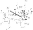
Fig. 1 is a front perspective view of a braking system in the engaged position according to an embodiment of the present invention; -
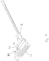
Fig. 2 is a front perspective view of the braking system in the disengaged position; -
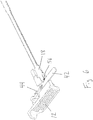
Fig. 3 is a rear perspective view of the braking system in the disengaged position; -
Fig. 4 is a perspective sectional view of the linking mechanism in the disengaged position, taken along line 4-4 inFig. 3 ; -
Fig. 5 is a rear perspective view of the braking system in the engaged position; -
Fig. 6 is a perspective sectional view of the linking mechanism in the engaged position with the right pedal being hidden from view, taken along line 6-6 inFig. 5 ; and -
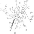
Fig. 7 is an exploded view illustrating the linking mechanism. - Corresponding reference characters indicate corresponding parts throughout the several views. The exemplification set out herein illustrates an embodiment, in one form, of the invention, and such exemplification is not to be construed as limiting the scope of the invention in any manner.
- Referring now to the drawings, and more specifically to
Figs. 1-3 , there is shown abraking system 10 which generally includes left andright brake pedals mechanism 16 that is coupled to theleft brake pedal 12, and asensor 18 that is coupled to theleft brake pedal 12. Thebraking system 10 may be incorporated as part of a work vehicle such as a tractor, a combine, a backhoe, etc. - The left and
right brake pedals right brake circuits brake pedals brake extension members brake pedals brake circuits brake circuits - Referring now to
Figs. 3-7 , there is shown the linkingmechanism 16 in greater detail as it is portrayed in the engaged position (Figs. 5 and6 ) and in the disengaged position (Figs. 3 and4 ). The linkingmechanism 16 may be mounted to the backside of theleft brake pedal 12 via receivingholes Fig. 7 ). The linkingmechanism 16 generally includes ahandle 40 pivotally connected to the back of theleft brake pedal 12, apin 42 moveably coupled to thehandle 40 by a connectingrod 44, and abiasing member 46 that is coupled to thehandle 40 and theleft brake pedal 12. The linkingmechanism 16 is configured for selectively linking thebrake pedals mechanism 16 is engaged, i.e., in the engaged position, thebrake pedals brake pedal brake pedals mechanism 16 is disengaged, i.e., in the disengaged position, thebrake pedals - The
handle 40, as shown more clearly inFig. 7 , may have a protrusion in the form of anelongated member 48. Theprotrusion 48 may at least partially extend beyond the outer periphery of theleft brake pedal 12. Theprotrusion 48 may extend outwardly to an end and/or it may include a rearwardly bent portion at its end. Thehandle 40 may also includefingers elongated member 48. Thefingers pin 42 and thebiasing member 46. Thehandle 40 may be pivotally connected to theleft pedal 12 at a connection point by a knownfastener 54. For example, ascrew 54 may be threaded into the receivinghole 34 of theleft brake pedal 12. - The body of the
handle 40 is located behind thepedal 12 and thereby theprotrusion 48 does not extend in front of theleft brake pedal 12 or otherwise interfere with the braking process. In other words, as theprotrusion 48 does not wrap around or partially extend in front of theleft brake pedal 12, and thus theprotrusion 48 does not interfere with the travel of an operator's foot as he applies a braking force to depress eitherpedal mechanism 16 will be undesirably engaged and/or disengaged. Also, as the location of theprotrusion 48 of thehandle 40 is located further from the hub of thebrake pedals - In the disengaged position, the
protrusion 48 extends outwardly to a side of the left pedal 12 (Fig. 3 ). In the engaged position, theprotrusion 48 extends substantially upwardly, and the end of theprotrusion 48 may be located above the topside of the left brake pedal 12 (Fig. 5 ). In this regard, an operator may contact theprotrusion 48 to engage and/or disengage thelinking mechanism 16. For example, an operator may use his foot to contact and move theprotrusion 48 of thehandle 40 in order to link thebrake pedals linking mechanism 16. Additionally, for example, an operator may not be able to use his foot to disengage thelinking mechanism 16 as the end of theprotrusion 48 is positioned substantially above theleft brake pedal 12. Instead, the operator may use his hand to move theprotrusion 48 of thehandle 40 to unlink thebrake pedals - The
pin 42 is axially moveable by actuation of thehandle 40. As thehandle 40 is rotated upwardly or downwardly, thepin 42 axially moves forwardly or backwardly, respectively. Thereby, thepin 42 selectively couples with theright brake pedal 14 as it axially slides back and forth. Thepin 42 is moveably coupled to the connectingrod 44, and in turn the connectingrod 44 is moveably coupled to thefinger 50 of thehandle 40. Thepin 42 may include acutout 56 that is associated with thesensor 18. Thecutout 56 may also include a cam profile such that thesensor 18 is selectively engaged by the cam profile (Fig. 6 ). Thepin 42 may be composed of any suitable metal, plastic, or composite material. - The biasing
member 46 is coupled at one end to theleft brake pedal 12 by alink 58, which is fitted into the receivinghole 36 of theleft brake pedal 12, and the biasingmember 46 is coupled to thefinger 52 of thehandle 40 at its other end. The biasingmember 46 may be in the form of aspring 46 which is configured to provide a biasing force on thelinking mechanism 16 in both of the engaged position and the disengaged position. In other words, as the operator moves thehandle 40 between the engaged and disengaged positions, the force of thespring 46 may overtake the dead center of thehandle 40, and may thereby hold thelinking mechanism 16 in either position. Additionally, thespring 46 may be configured to tune the force required in order to change the position of the linkingmechanism 16. For example, the operation, e.g. rotating thehandle 40, to engage thelinking mechanism 16 may be easier compared to the operation of disengaging the linkingmechanism 16. Further, for example, the engaging of the linkingmechanism 16 may be accomplished by a slight kick on theprotrusion 48 of thehandle 40 by the operator. In the present embodiment, thespring 46 is atorsion spring 46; however, any suitable spring may be used including a torsion and tension spring. It should be appreciated that the biasingmember 46 may not be a spring but instead may be in the form of any desired biasing member such as an elastic member (not shown). - The
sensor 18 is coupled to theleft brake pedal 12 and is configured for sensing an engagement status and a disengagement status of the linkingmechanism 16. The engagement status and the disengagement status respectively correspond to the engaged position and the disengaged position of the linkingmechanism 16. Thesensor 18 may be in the form of amechanical sensor 18 with a moveable tip which engages with thecutout 56 of thepin 42. For example, thesensor 18 may be in the form for a mechanical status switch. The tip ofsensor 18 may contact thepin 42 as it axially translates back and forth. Thereby, the tip ofsensor 18 may move forwardly and rearwardly relative to theleft brake pedal 12 as an end of thesensor 18 engages and disengages with thecutout 56 of thepin 42. When thesensor 18 is not engaged with the cam profile of thecutout 56, thesensor 18 provides the disengagement status (Fig. 4 ). When thesensor 18 engages with the cam profile of thecutout 56, thesensor 18 provides the engagement status (Fig. 6 ). Thesensor 18 may communicate the engagement status and/or the disengagement status to an electronic control unit (ECU) 60 of the work vehicle (Fig. 1 ). TheECU 60 of the work vehicle may be in the form of any desired control unit, such as a vehicle control unit (VCU). Once the status of the linkingmechanism 16 is communicated to theECU 60 by thesensor 18, theECU 60 may signal an indicator light and/or a display graphic to notify the operator of the status of the linkingmechanism 16. TheECU 60 may further interact with the vehicle brake logic and/or vehicle speed. - Alternatively, the
sensor 18 may be a hall effect sensor detecting movement of a magnet positioned onpin 42 to provide engagement status and/or disengagement status to theECU 60. - The linking
mechanism 16 may also include aposterior housing member 28 that has bores 30, 32 to respectively house thepin 42 and thesensor 18. Thepin 42 may axially slide within thebore 30, and thesensor 18 may move up and down within thebore 32 as thepin 42 slides back and forth. Theposterior housing member 28 may be monolithically formed as part of theleft brake pedal 12, or theposterior housing member 28 may be fixedly attached to the left brake pedal 12 (Fig. 7 ). The leftbrake extension member 24 may couple to the backside of theposterior housing member 28. Additionally, the linkingmechanism 16 may include abore 38 that is located on theright brake pedal 14. For example, the rightbrake extension member 26 may include the bore 38 (Fig. 3 ), or theright brake pedal 14 may additionally include a posterior housing member with a bore (not shown). Thebore 38 of theright brake pedal 14 may be coaxially aligned with thebore 30 of theleft brake pedal 12 when thebrake pedals brake pedals mechanism 16 is in the engaged position when thepin 42 is at least partially positioned within thebore 38 of theright brake pedal 14, and thelinking mechanism 16 is in the disengaged position when thepin 42 is not within thebore 38 of theright brake pedal 14. - It should be appreciated that the linking
mechanism 16 and thesensor 18 may be coupled to eitherbrake pedal mechanism 16 may be coupled to theright brake pedal 14 instead of theleft brake pedal 12 as shown. In this regard, the various components of the left andright brake pedals - The present invention provides that the sensor accurately senses the position of the pin of the linking mechanism in order to notify the operator of the linked and unlinked position of the brake pedals. The present invention also provides that the linking mechanism may be easily engaged by an operator without having the operator remove his hands from the wheel during operation of the work vehicle. The present invention further provides that the linking mechanism is biased such that it is configured to be held in the engaged position and the disengaged position.
- While this invention has been described with respect to at least one embodiment, the present invention can be further modified within the spirit and scope of this disclosure. This application is therefore intended to cover any variations, uses, or adaptations of the invention using its general principles. Further, this application is intended to cover such departures from the present disclosure as come within known or customary practice in the art to which this invention pertains and which fall within the limits of the appended claims.
Claims (15)
- A braking system (10) for a work vehicle, comprising:a first brake pedal (12) configured for activating a first brake circuit (20);a second brake pedal (14) configured for activating a second brake circuit (22);characterized by:a linking mechanism (16) coupled to the first brake pedal (12) and configured for selectively linking the first brake pedal (12) and the second brake pedal (14) together; anda sensor (18) coupled to the first brake pedal (12) and configured for sensing an engagement status and a disengagement status of the linking mechanism (16).
- The braking system (10) of claim 1, wherein said linking mechanism (16) includes a handle (40) pivotally connected to the first brake pedal (12) and a pin (42) moveably coupled to the handle (40).
- The braking system (10) of claim 2, wherein said pin (42) is axially moveable by actuation of said handle (40) to selectively couple with the said second brake pedal (14).
- The braking system (10) of claim 2, wherein said handle (40) includes a protrusion (48) such that said protrusion (48) at least partially extends beyond an outer periphery of said first brake pedal (12).
- The braking system (10) of claim 4, wherein said protrusion (48) is configured such that said linking mechanism (16) is engageable by a foot of an operator which contacts said protrusion (48) of the handle (40) in order to link said first brake pedal (12) and said second brake pedal (14), and said linking mechanism (16) is not disengageable by the foot of the operator in order to unlink said first brake pedal (12) and said second brake pedal (14).
- The braking system (10) of claim 2, wherein said pin (42) has a cutout (56) which is associated with a moveable tip of said sensor (18).
- The braking system (10) of claim 6, wherein said cutout (56) includes a cam profile, and said sensor (18) is selectively engaged by said cam profile.
- The braking system (10) of claim 7, wherein said sensor (18) senses said engagement status upon engaging with said cam profile.
- The braking system (10) of claims 2-8, wherein said pin (42) is moveably coupled to said handle (40) by a connecting rod (44) such that rotation of the handle (40) slides the pin (42) in order to link and unlink said first brake pedal (12) and said second brake pedal (14).
- The braking system (10) of claim any of the preceding claims, wherein said linking mechanism (16) further includes a biasing member (46) coupled to the handle (40) and the first brake pedal (12).
- The braking system (10) of claim 10, wherein said biasing member (46) is in the form of a spring (46) which is configured to bias said linking mechanism (16) in an engaged position and a disengaged position.
- The braking system (10) of any of the preceding claims, wherein said sensor (18) communicates said engagement status to an ECU (60).
- The braking system (10) of any of the preceding claims, wherein said linking mechanism (16) is coupled to a back surface of the first brake pedal (12) such that said linking mechanism (16) is located behind the first brake pedal (12).
- The braking system (10) of claims 2-9, wherein said first brake pedal (12) includes a posterior housing member (28) that has a first bore (30) for receiving at least a portion of said pin (42) such that said pin (42) axially slides within said first bore (30), and said second brake pedal (14) includes a second bore (38) that can be coaxially aligned with said first bore (30) of the first brake pedal (12).
- The braking system (10) of claim 14, wherein said bore (38) of said second brake pedal (14) receives at least a portion of said pin (42) of said linking mechanism (16) upon engaging the linking mechanism (16).
Priority Applications (1)
| Application Number | Priority Date | Filing Date | Title |
|---|---|---|---|
| EP17179142.9A EP3421310B1 (en) | 2017-06-30 | 2017-06-30 | A brake pedal latching with electric status indication signal |
Applications Claiming Priority (1)
| Application Number | Priority Date | Filing Date | Title |
|---|---|---|---|
| EP17179142.9A EP3421310B1 (en) | 2017-06-30 | 2017-06-30 | A brake pedal latching with electric status indication signal |
Publications (2)
| Publication Number | Publication Date |
|---|---|
| EP3421310A1 true EP3421310A1 (en) | 2019-01-02 |
| EP3421310B1 EP3421310B1 (en) | 2020-12-09 |
Family
ID=59296710
Family Applications (1)
| Application Number | Title | Priority Date | Filing Date |
|---|---|---|---|
| EP17179142.9A Active EP3421310B1 (en) | 2017-06-30 | 2017-06-30 | A brake pedal latching with electric status indication signal |
Country Status (1)
| Country | Link |
|---|---|
| EP (1) | EP3421310B1 (en) |
Citations (4)
| Publication number | Priority date | Publication date | Assignee | Title |
|---|---|---|---|---|
| US4299136A (en) * | 1979-04-20 | 1981-11-10 | Dr. Ing. H.C.F. Porsche Ag | Locking system for two brake pedals of a motor vehicle mounted on a common shaft |
| EP1099993B1 (en) * | 1999-11-11 | 2010-04-21 | CNH Italia S.p.A. | Vehicle control device, in particular for agricultural vehicles |
| GB2466065A (en) | 2008-12-12 | 2010-06-16 | Agco Gmbh | Braking system having left and right brake pedals that are lockable together, and warning means to indicate the pedals are unlocked |
| WO2017001992A1 (en) * | 2015-06-30 | 2017-01-05 | Lodi S.P.A. | A pedalboard with safety system for tractors |
-
2017
- 2017-06-30 EP EP17179142.9A patent/EP3421310B1/en active Active
Patent Citations (4)
| Publication number | Priority date | Publication date | Assignee | Title |
|---|---|---|---|---|
| US4299136A (en) * | 1979-04-20 | 1981-11-10 | Dr. Ing. H.C.F. Porsche Ag | Locking system for two brake pedals of a motor vehicle mounted on a common shaft |
| EP1099993B1 (en) * | 1999-11-11 | 2010-04-21 | CNH Italia S.p.A. | Vehicle control device, in particular for agricultural vehicles |
| GB2466065A (en) | 2008-12-12 | 2010-06-16 | Agco Gmbh | Braking system having left and right brake pedals that are lockable together, and warning means to indicate the pedals are unlocked |
| WO2017001992A1 (en) * | 2015-06-30 | 2017-01-05 | Lodi S.P.A. | A pedalboard with safety system for tractors |
Also Published As
| Publication number | Publication date |
|---|---|
| EP3421310B1 (en) | 2020-12-09 |
Similar Documents
| Publication | Publication Date | Title |
|---|---|---|
| JP3781864B2 (en) | Automotive brake pedal equipment | |
| EP2210804B1 (en) | Bicycle control device | |
| US20110036196A1 (en) | Electronic throttle control device for motorcycles, snowmobiles and similar vehicles | |
| JP5843283B2 (en) | Vehicle input device | |
| US11981391B2 (en) | Operating device for human-powered vehicle | |
| JP7472850B2 (en) | Pedal device | |
| US8726758B2 (en) | Arrangement structure of parking brake lever and arrangement structure of operating lever in vehicle | |
| US7278367B1 (en) | Marine vessel steering wheel with integrated throttle control device | |
| TW201444729A (en) | Operating device | |
| US20210323624A1 (en) | Bicycle operating apparatus | |
| US20240300456A1 (en) | Brake pedal system for a motor vehicle | |
| WO2008052051A2 (en) | Aircraft brake actuation measurement unit | |
| US20140060238A1 (en) | Device for preventing inward shifting of brake pedal during collision | |
| EP3421310B1 (en) | A brake pedal latching with electric status indication signal | |
| US4662237A (en) | Actuating device for automobiles | |
| JP2007153270A (en) | Interlocking brake mechanism for bar handle vehicles | |
| JP2013032115A (en) | Braking device of vehicle | |
| JP6706586B2 (en) | Vehicle operation pedal device | |
| CN212570814U (en) | Steering column combination switch with four handles | |
| WO2020012696A1 (en) | Operation pedal device for vehicle | |
| US20260078618A1 (en) | Handle arrangement and vehicle door | |
| US20040144195A1 (en) | Brake control device on steering wheel | |
| US12594878B2 (en) | Turn signal switch device | |
| TW202019751A (en) | Control method for accessory of vehicle | |
| CA2652246C (en) | Throttle control apparatus for a snowmobile |
Legal Events
| Date | Code | Title | Description |
|---|---|---|---|
| PUAI | Public reference made under article 153(3) epc to a published international application that has entered the european phase |
Free format text: ORIGINAL CODE: 0009012 |
|
| STAA | Information on the status of an ep patent application or granted ep patent |
Free format text: STATUS: THE APPLICATION HAS BEEN PUBLISHED |
|
| AK | Designated contracting states |
Kind code of ref document: A1 Designated state(s): AL AT BE BG CH CY CZ DE DK EE ES FI FR GB GR HR HU IE IS IT LI LT LU LV MC MK MT NL NO PL PT RO RS SE SI SK SM TR |
|
| AX | Request for extension of the european patent |
Extension state: BA ME |
|
| STAA | Information on the status of an ep patent application or granted ep patent |
Free format text: STATUS: REQUEST FOR EXAMINATION WAS MADE |
|
| 17P | Request for examination filed |
Effective date: 20190702 |
|
| RBV | Designated contracting states (corrected) |
Designated state(s): AL AT BE BG CH CY CZ DE DK EE ES FI FR GB GR HR HU IE IS IT LI LT LU LV MC MK MT NL NO PL PT RO RS SE SI SK SM TR |
|
| REG | Reference to a national code |
Ref country code: DE Ref legal event code: R079 Ref document number: 602017029123 Country of ref document: DE Free format text: PREVIOUS MAIN CLASS: B60T0011210000 Ipc: B60T0007040000 |
|
| GRAP | Despatch of communication of intention to grant a patent |
Free format text: ORIGINAL CODE: EPIDOSNIGR1 |
|
| STAA | Information on the status of an ep patent application or granted ep patent |
Free format text: STATUS: GRANT OF PATENT IS INTENDED |
|
| RIC1 | Information provided on ipc code assigned before grant |
Ipc: G05G 1/44 20080401ALN20200608BHEP Ipc: B60T 7/04 20060101AFI20200608BHEP Ipc: B60T 7/06 20060101ALI20200608BHEP Ipc: B60T 11/18 20060101ALI20200608BHEP Ipc: B60T 11/21 20060101ALN20200608BHEP Ipc: G05G 13/00 20060101ALI20200608BHEP Ipc: B60T 8/00 20060101ALI20200608BHEP |
|
| INTG | Intention to grant announced |
Effective date: 20200626 |
|
| GRAS | Grant fee paid |
Free format text: ORIGINAL CODE: EPIDOSNIGR3 |
|
| GRAA | (expected) grant |
Free format text: ORIGINAL CODE: 0009210 |
|
| STAA | Information on the status of an ep patent application or granted ep patent |
Free format text: STATUS: THE PATENT HAS BEEN GRANTED |
|
| AK | Designated contracting states |
Kind code of ref document: B1 Designated state(s): AL AT BE BG CH CY CZ DE DK EE ES FI FR GB GR HR HU IE IS IT LI LT LU LV MC MK MT NL NO PL PT RO RS SE SI SK SM TR |
|
| REG | Reference to a national code |
Ref country code: GB Ref legal event code: FG4D |
|
| REG | Reference to a national code |
Ref country code: AT Ref legal event code: REF Ref document number: 1343114 Country of ref document: AT Kind code of ref document: T Effective date: 20201215 Ref country code: CH Ref legal event code: EP |
|
| REG | Reference to a national code |
Ref country code: DE Ref legal event code: R096 Ref document number: 602017029123 Country of ref document: DE |
|
| REG | Reference to a national code |
Ref country code: IE Ref legal event code: FG4D |
|
| PG25 | Lapsed in a contracting state [announced via postgrant information from national office to epo] |
Ref country code: FI Free format text: LAPSE BECAUSE OF FAILURE TO SUBMIT A TRANSLATION OF THE DESCRIPTION OR TO PAY THE FEE WITHIN THE PRESCRIBED TIME-LIMIT Effective date: 20201209 Ref country code: GR Free format text: LAPSE BECAUSE OF FAILURE TO SUBMIT A TRANSLATION OF THE DESCRIPTION OR TO PAY THE FEE WITHIN THE PRESCRIBED TIME-LIMIT Effective date: 20210310 Ref country code: NO Free format text: LAPSE BECAUSE OF FAILURE TO SUBMIT A TRANSLATION OF THE DESCRIPTION OR TO PAY THE FEE WITHIN THE PRESCRIBED TIME-LIMIT Effective date: 20210309 Ref country code: RS Free format text: LAPSE BECAUSE OF FAILURE TO SUBMIT A TRANSLATION OF THE DESCRIPTION OR TO PAY THE FEE WITHIN THE PRESCRIBED TIME-LIMIT Effective date: 20201209 |
|
| REG | Reference to a national code |
Ref country code: AT Ref legal event code: MK05 Ref document number: 1343114 Country of ref document: AT Kind code of ref document: T Effective date: 20201209 |
|
| PG25 | Lapsed in a contracting state [announced via postgrant information from national office to epo] |
Ref country code: LV Free format text: LAPSE BECAUSE OF FAILURE TO SUBMIT A TRANSLATION OF THE DESCRIPTION OR TO PAY THE FEE WITHIN THE PRESCRIBED TIME-LIMIT Effective date: 20201209 Ref country code: BG Free format text: LAPSE BECAUSE OF FAILURE TO SUBMIT A TRANSLATION OF THE DESCRIPTION OR TO PAY THE FEE WITHIN THE PRESCRIBED TIME-LIMIT Effective date: 20210309 Ref country code: SE Free format text: LAPSE BECAUSE OF FAILURE TO SUBMIT A TRANSLATION OF THE DESCRIPTION OR TO PAY THE FEE WITHIN THE PRESCRIBED TIME-LIMIT Effective date: 20201209 |
|
| REG | Reference to a national code |
Ref country code: NL Ref legal event code: MP Effective date: 20201209 |
|
| PG25 | Lapsed in a contracting state [announced via postgrant information from national office to epo] |
Ref country code: NL Free format text: LAPSE BECAUSE OF FAILURE TO SUBMIT A TRANSLATION OF THE DESCRIPTION OR TO PAY THE FEE WITHIN THE PRESCRIBED TIME-LIMIT Effective date: 20201209 Ref country code: HR Free format text: LAPSE BECAUSE OF FAILURE TO SUBMIT A TRANSLATION OF THE DESCRIPTION OR TO PAY THE FEE WITHIN THE PRESCRIBED TIME-LIMIT Effective date: 20201209 |
|
| REG | Reference to a national code |
Ref country code: LT Ref legal event code: MG9D |
|
| PG25 | Lapsed in a contracting state [announced via postgrant information from national office to epo] |
Ref country code: SK Free format text: LAPSE BECAUSE OF FAILURE TO SUBMIT A TRANSLATION OF THE DESCRIPTION OR TO PAY THE FEE WITHIN THE PRESCRIBED TIME-LIMIT Effective date: 20201209 Ref country code: PT Free format text: LAPSE BECAUSE OF FAILURE TO SUBMIT A TRANSLATION OF THE DESCRIPTION OR TO PAY THE FEE WITHIN THE PRESCRIBED TIME-LIMIT Effective date: 20210409 Ref country code: RO Free format text: LAPSE BECAUSE OF FAILURE TO SUBMIT A TRANSLATION OF THE DESCRIPTION OR TO PAY THE FEE WITHIN THE PRESCRIBED TIME-LIMIT Effective date: 20201209 Ref country code: LT Free format text: LAPSE BECAUSE OF FAILURE TO SUBMIT A TRANSLATION OF THE DESCRIPTION OR TO PAY THE FEE WITHIN THE PRESCRIBED TIME-LIMIT Effective date: 20201209 Ref country code: SM Free format text: LAPSE BECAUSE OF FAILURE TO SUBMIT A TRANSLATION OF THE DESCRIPTION OR TO PAY THE FEE WITHIN THE PRESCRIBED TIME-LIMIT Effective date: 20201209 Ref country code: EE Free format text: LAPSE BECAUSE OF FAILURE TO SUBMIT A TRANSLATION OF THE DESCRIPTION OR TO PAY THE FEE WITHIN THE PRESCRIBED TIME-LIMIT Effective date: 20201209 Ref country code: CZ Free format text: LAPSE BECAUSE OF FAILURE TO SUBMIT A TRANSLATION OF THE DESCRIPTION OR TO PAY THE FEE WITHIN THE PRESCRIBED TIME-LIMIT Effective date: 20201209 |
|
| PG25 | Lapsed in a contracting state [announced via postgrant information from national office to epo] |
Ref country code: AT Free format text: LAPSE BECAUSE OF FAILURE TO SUBMIT A TRANSLATION OF THE DESCRIPTION OR TO PAY THE FEE WITHIN THE PRESCRIBED TIME-LIMIT Effective date: 20201209 Ref country code: PL Free format text: LAPSE BECAUSE OF FAILURE TO SUBMIT A TRANSLATION OF THE DESCRIPTION OR TO PAY THE FEE WITHIN THE PRESCRIBED TIME-LIMIT Effective date: 20201209 |
|
| REG | Reference to a national code |
Ref country code: DE Ref legal event code: R097 Ref document number: 602017029123 Country of ref document: DE |
|
| PG25 | Lapsed in a contracting state [announced via postgrant information from national office to epo] |
Ref country code: IS Free format text: LAPSE BECAUSE OF FAILURE TO SUBMIT A TRANSLATION OF THE DESCRIPTION OR TO PAY THE FEE WITHIN THE PRESCRIBED TIME-LIMIT Effective date: 20210409 |
|
| PLBE | No opposition filed within time limit |
Free format text: ORIGINAL CODE: 0009261 |
|
| STAA | Information on the status of an ep patent application or granted ep patent |
Free format text: STATUS: NO OPPOSITION FILED WITHIN TIME LIMIT |
|
| PG25 | Lapsed in a contracting state [announced via postgrant information from national office to epo] |
Ref country code: AL Free format text: LAPSE BECAUSE OF FAILURE TO SUBMIT A TRANSLATION OF THE DESCRIPTION OR TO PAY THE FEE WITHIN THE PRESCRIBED TIME-LIMIT Effective date: 20201209 |
|
| 26N | No opposition filed |
Effective date: 20210910 |
|
| PG25 | Lapsed in a contracting state [announced via postgrant information from national office to epo] |
Ref country code: DK Free format text: LAPSE BECAUSE OF FAILURE TO SUBMIT A TRANSLATION OF THE DESCRIPTION OR TO PAY THE FEE WITHIN THE PRESCRIBED TIME-LIMIT Effective date: 20201209 Ref country code: SI Free format text: LAPSE BECAUSE OF FAILURE TO SUBMIT A TRANSLATION OF THE DESCRIPTION OR TO PAY THE FEE WITHIN THE PRESCRIBED TIME-LIMIT Effective date: 20201209 |
|
| PG25 | Lapsed in a contracting state [announced via postgrant information from national office to epo] |
Ref country code: MC Free format text: LAPSE BECAUSE OF FAILURE TO SUBMIT A TRANSLATION OF THE DESCRIPTION OR TO PAY THE FEE WITHIN THE PRESCRIBED TIME-LIMIT Effective date: 20201209 Ref country code: ES Free format text: LAPSE BECAUSE OF FAILURE TO SUBMIT A TRANSLATION OF THE DESCRIPTION OR TO PAY THE FEE WITHIN THE PRESCRIBED TIME-LIMIT Effective date: 20201209 |
|
| REG | Reference to a national code |
Ref country code: CH Ref legal event code: PL |
|
| REG | Reference to a national code |
Ref country code: BE Ref legal event code: MM Effective date: 20210630 |
|
| PG25 | Lapsed in a contracting state [announced via postgrant information from national office to epo] |
Ref country code: LU Free format text: LAPSE BECAUSE OF NON-PAYMENT OF DUE FEES Effective date: 20210630 |
|
| PG25 | Lapsed in a contracting state [announced via postgrant information from national office to epo] |
Ref country code: LI Free format text: LAPSE BECAUSE OF NON-PAYMENT OF DUE FEES Effective date: 20210630 Ref country code: IE Free format text: LAPSE BECAUSE OF NON-PAYMENT OF DUE FEES Effective date: 20210630 Ref country code: CH Free format text: LAPSE BECAUSE OF NON-PAYMENT OF DUE FEES Effective date: 20210630 |
|
| PG25 | Lapsed in a contracting state [announced via postgrant information from national office to epo] |
Ref country code: IS Free format text: LAPSE BECAUSE OF FAILURE TO SUBMIT A TRANSLATION OF THE DESCRIPTION OR TO PAY THE FEE WITHIN THE PRESCRIBED TIME-LIMIT Effective date: 20210409 |
|
| PG25 | Lapsed in a contracting state [announced via postgrant information from national office to epo] |
Ref country code: BE Free format text: LAPSE BECAUSE OF NON-PAYMENT OF DUE FEES Effective date: 20210630 |
|
| PG25 | Lapsed in a contracting state [announced via postgrant information from national office to epo] |
Ref country code: CY Free format text: LAPSE BECAUSE OF FAILURE TO SUBMIT A TRANSLATION OF THE DESCRIPTION OR TO PAY THE FEE WITHIN THE PRESCRIBED TIME-LIMIT Effective date: 20201209 |
|
| PG25 | Lapsed in a contracting state [announced via postgrant information from national office to epo] |
Ref country code: HU Free format text: LAPSE BECAUSE OF FAILURE TO SUBMIT A TRANSLATION OF THE DESCRIPTION OR TO PAY THE FEE WITHIN THE PRESCRIBED TIME-LIMIT; INVALID AB INITIO Effective date: 20170630 |
|
| PG25 | Lapsed in a contracting state [announced via postgrant information from national office to epo] |
Ref country code: MK Free format text: LAPSE BECAUSE OF FAILURE TO SUBMIT A TRANSLATION OF THE DESCRIPTION OR TO PAY THE FEE WITHIN THE PRESCRIBED TIME-LIMIT Effective date: 20201209 |
|
| PG25 | Lapsed in a contracting state [announced via postgrant information from national office to epo] |
Ref country code: TR Free format text: LAPSE BECAUSE OF FAILURE TO SUBMIT A TRANSLATION OF THE DESCRIPTION OR TO PAY THE FEE WITHIN THE PRESCRIBED TIME-LIMIT Effective date: 20201209 |
|
| PG25 | Lapsed in a contracting state [announced via postgrant information from national office to epo] |
Ref country code: MT Free format text: LAPSE BECAUSE OF FAILURE TO SUBMIT A TRANSLATION OF THE DESCRIPTION OR TO PAY THE FEE WITHIN THE PRESCRIBED TIME-LIMIT Effective date: 20201209 |
|
| PGFP | Annual fee paid to national office [announced via postgrant information from national office to epo] |
Ref country code: GB Payment date: 20260622 Year of fee payment: 10 |
|
| PGFP | Annual fee paid to national office [announced via postgrant information from national office to epo] |
Ref country code: IT Payment date: 20260623 Year of fee payment: 10 |
|
| PGFP | Annual fee paid to national office [announced via postgrant information from national office to epo] |
Ref country code: DE Payment date: 20260623 Year of fee payment: 10 |
|
| PGFP | Annual fee paid to national office [announced via postgrant information from national office to epo] |
Ref country code: FR Payment date: 20260622 Year of fee payment: 10 |