EP3421125A1 - Filler for packed tower and seawater desulfurization device - Google Patents
Filler for packed tower and seawater desulfurization device Download PDFInfo
- Publication number
- EP3421125A1 EP3421125A1 EP17773594.1A EP17773594A EP3421125A1 EP 3421125 A1 EP3421125 A1 EP 3421125A1 EP 17773594 A EP17773594 A EP 17773594A EP 3421125 A1 EP3421125 A1 EP 3421125A1
- Authority
- EP
- European Patent Office
- Prior art keywords
- plate
- filler
- vertical direction
- filling
- plate unit
- Prior art date
- Legal status (The legal status is an assumption and is not a legal conclusion. Google has not performed a legal analysis and makes no representation as to the accuracy of the status listed.)
- Withdrawn
Links
- 239000000945 filler Substances 0.000 title claims abstract description 180
- 239000013535 sea water Substances 0.000 title claims description 120
- 238000006477 desulfuration reaction Methods 0.000 title claims description 30
- 230000023556 desulfurization Effects 0.000 title claims description 30
- XLYOFNOQVPJJNP-UHFFFAOYSA-N water Substances O XLYOFNOQVPJJNP-UHFFFAOYSA-N 0.000 claims abstract description 55
- UGFAIRIUMAVXCW-UHFFFAOYSA-N Carbon monoxide Chemical compound [O+]#[C-] UGFAIRIUMAVXCW-UHFFFAOYSA-N 0.000 claims description 52
- 239000003546 flue gas Substances 0.000 claims description 52
- NINIDFKCEFEMDL-UHFFFAOYSA-N Sulfur Chemical compound [S] NINIDFKCEFEMDL-UHFFFAOYSA-N 0.000 abstract description 19
- 229910052717 sulfur Inorganic materials 0.000 abstract description 19
- 239000011593 sulfur Substances 0.000 abstract description 19
- 239000002912 waste gas Substances 0.000 abstract 2
- 230000007423 decrease Effects 0.000 abstract 1
- 239000007788 liquid Substances 0.000 description 44
- 230000001965 increasing effect Effects 0.000 description 20
- 238000010586 diagram Methods 0.000 description 15
- 238000007254 oxidation reaction Methods 0.000 description 10
- 238000010521 absorption reaction Methods 0.000 description 9
- 238000002156 mixing Methods 0.000 description 9
- 230000003647 oxidation Effects 0.000 description 9
- 238000007865 diluting Methods 0.000 description 8
- 230000002378 acidificating effect Effects 0.000 description 7
- 239000006096 absorbing agent Substances 0.000 description 5
- LSNNMFCWUKXFEE-UHFFFAOYSA-M Bisulfite Chemical compound OS([O-])=O LSNNMFCWUKXFEE-UHFFFAOYSA-M 0.000 description 4
- QVGXLLKOCUKJST-UHFFFAOYSA-N atomic oxygen Chemical compound [O] QVGXLLKOCUKJST-UHFFFAOYSA-N 0.000 description 4
- 238000010790 dilution Methods 0.000 description 4
- 239000012895 dilution Substances 0.000 description 4
- 229910052760 oxygen Inorganic materials 0.000 description 4
- 239000001301 oxygen Substances 0.000 description 4
- BVKZGUZCCUSVTD-UHFFFAOYSA-M Bicarbonate Chemical compound OC([O-])=O BVKZGUZCCUSVTD-UHFFFAOYSA-M 0.000 description 3
- 230000002745 absorbent Effects 0.000 description 3
- 239000002250 absorbent Substances 0.000 description 3
- 230000000694 effects Effects 0.000 description 3
- 238000000034 method Methods 0.000 description 3
- LSNNMFCWUKXFEE-UHFFFAOYSA-N Sulfurous acid Chemical compound OS(O)=O LSNNMFCWUKXFEE-UHFFFAOYSA-N 0.000 description 2
- 239000000428 dust Substances 0.000 description 2
- 239000000126 substance Substances 0.000 description 2
- YZCKVEUIGOORGS-UHFFFAOYSA-N Hydrogen atom Chemical compound [H] YZCKVEUIGOORGS-UHFFFAOYSA-N 0.000 description 1
- 238000005273 aeration Methods 0.000 description 1
- 238000006243 chemical reaction Methods 0.000 description 1
- 239000003245 coal Substances 0.000 description 1
- 239000012141 concentrate Substances 0.000 description 1
- 239000002826 coolant Substances 0.000 description 1
- 238000001816 cooling Methods 0.000 description 1
- 238000006114 decarboxylation reaction Methods 0.000 description 1
- 238000010612 desalination reaction Methods 0.000 description 1
- 230000002708 enhancing effect Effects 0.000 description 1
- 239000002803 fossil fuel Substances 0.000 description 1
- 239000007789 gas Substances 0.000 description 1
- 229910052602 gypsum Inorganic materials 0.000 description 1
- 239000010440 gypsum Substances 0.000 description 1
- 238000004519 manufacturing process Methods 0.000 description 1
- 239000011159 matrix material Substances 0.000 description 1
- 239000000243 solution Substances 0.000 description 1
Images







Classifications
-
- B—PERFORMING OPERATIONS; TRANSPORTING
- B01—PHYSICAL OR CHEMICAL PROCESSES OR APPARATUS IN GENERAL
- B01D—SEPARATION
- B01D53/00—Separation of gases or vapours; Recovering vapours of volatile solvents from gases; Chemical or biological purification of waste gases, e.g. engine exhaust gases, smoke, fumes, flue gases, aerosols
- B01D53/14—Separation of gases or vapours; Recovering vapours of volatile solvents from gases; Chemical or biological purification of waste gases, e.g. engine exhaust gases, smoke, fumes, flue gases, aerosols by absorption
- B01D53/1456—Removing acid components
-
- B—PERFORMING OPERATIONS; TRANSPORTING
- B01—PHYSICAL OR CHEMICAL PROCESSES OR APPARATUS IN GENERAL
- B01D—SEPARATION
- B01D3/00—Distillation or related exchange processes in which liquids are contacted with gaseous media, e.g. stripping
- B01D3/14—Fractional distillation or use of a fractionation or rectification column
- B01D3/26—Fractionating columns in which vapour and liquid flow past each other, or in which the fluid is sprayed into the vapour, or in which a two-phase mixture is passed in one direction
- B01D3/28—Fractionating columns with surface contact and vertical guides, e.g. film action
-
- B—PERFORMING OPERATIONS; TRANSPORTING
- B01—PHYSICAL OR CHEMICAL PROCESSES OR APPARATUS IN GENERAL
- B01D—SEPARATION
- B01D53/00—Separation of gases or vapours; Recovering vapours of volatile solvents from gases; Chemical or biological purification of waste gases, e.g. engine exhaust gases, smoke, fumes, flue gases, aerosols
- B01D53/14—Separation of gases or vapours; Recovering vapours of volatile solvents from gases; Chemical or biological purification of waste gases, e.g. engine exhaust gases, smoke, fumes, flue gases, aerosols by absorption
- B01D53/18—Absorbing units; Liquid distributors therefor
-
- B—PERFORMING OPERATIONS; TRANSPORTING
- B01—PHYSICAL OR CHEMICAL PROCESSES OR APPARATUS IN GENERAL
- B01D—SEPARATION
- B01D53/00—Separation of gases or vapours; Recovering vapours of volatile solvents from gases; Chemical or biological purification of waste gases, e.g. engine exhaust gases, smoke, fumes, flue gases, aerosols
- B01D53/34—Chemical or biological purification of waste gases
- B01D53/46—Removing components of defined structure
- B01D53/48—Sulfur compounds
- B01D53/50—Sulfur oxides
-
- B—PERFORMING OPERATIONS; TRANSPORTING
- B01—PHYSICAL OR CHEMICAL PROCESSES OR APPARATUS IN GENERAL
- B01D—SEPARATION
- B01D53/00—Separation of gases or vapours; Recovering vapours of volatile solvents from gases; Chemical or biological purification of waste gases, e.g. engine exhaust gases, smoke, fumes, flue gases, aerosols
- B01D53/34—Chemical or biological purification of waste gases
- B01D53/74—General processes for purification of waste gases; Apparatus or devices specially adapted therefor
- B01D53/77—Liquid phase processes
- B01D53/78—Liquid phase processes with gas-liquid contact
-
- B—PERFORMING OPERATIONS; TRANSPORTING
- B01—PHYSICAL OR CHEMICAL PROCESSES OR APPARATUS IN GENERAL
- B01J—CHEMICAL OR PHYSICAL PROCESSES, e.g. CATALYSIS OR COLLOID CHEMISTRY; THEIR RELEVANT APPARATUS
- B01J19/00—Chemical, physical or physico-chemical processes in general; Their relevant apparatus
- B01J19/32—Packing elements in the form of grids or built-up elements for forming a unit or module inside the apparatus for mass or heat transfer
-
- B—PERFORMING OPERATIONS; TRANSPORTING
- B01—PHYSICAL OR CHEMICAL PROCESSES OR APPARATUS IN GENERAL
- B01D—SEPARATION
- B01D2251/00—Reactants
- B01D2251/10—Oxidants
- B01D2251/11—Air
-
- B—PERFORMING OPERATIONS; TRANSPORTING
- B01—PHYSICAL OR CHEMICAL PROCESSES OR APPARATUS IN GENERAL
- B01D—SEPARATION
- B01D2251/00—Reactants
- B01D2251/60—Inorganic bases or salts
- B01D2251/606—Carbonates
-
- B—PERFORMING OPERATIONS; TRANSPORTING
- B01—PHYSICAL OR CHEMICAL PROCESSES OR APPARATUS IN GENERAL
- B01D—SEPARATION
- B01D2252/00—Absorbents, i.e. solvents and liquid materials for gas absorption
- B01D2252/10—Inorganic absorbents
- B01D2252/103—Water
- B01D2252/1035—Sea water
-
- B—PERFORMING OPERATIONS; TRANSPORTING
- B01—PHYSICAL OR CHEMICAL PROCESSES OR APPARATUS IN GENERAL
- B01D—SEPARATION
- B01D2257/00—Components to be removed
- B01D2257/30—Sulfur compounds
- B01D2257/302—Sulfur oxides
-
- B—PERFORMING OPERATIONS; TRANSPORTING
- B01—PHYSICAL OR CHEMICAL PROCESSES OR APPARATUS IN GENERAL
- B01D—SEPARATION
- B01D2258/00—Sources of waste gases
- B01D2258/02—Other waste gases
- B01D2258/0283—Flue gases
-
- B—PERFORMING OPERATIONS; TRANSPORTING
- B01—PHYSICAL OR CHEMICAL PROCESSES OR APPARATUS IN GENERAL
- B01D—SEPARATION
- B01D53/00—Separation of gases or vapours; Recovering vapours of volatile solvents from gases; Chemical or biological purification of waste gases, e.g. engine exhaust gases, smoke, fumes, flue gases, aerosols
- B01D53/34—Chemical or biological purification of waste gases
- B01D53/46—Removing components of defined structure
- B01D53/48—Sulfur compounds
- B01D53/50—Sulfur oxides
- B01D53/501—Sulfur oxides by treating the gases with a solution or a suspension of an alkali or earth-alkali or ammonium compound
- B01D53/504—Sulfur oxides by treating the gases with a solution or a suspension of an alkali or earth-alkali or ammonium compound characterised by a specific device
Definitions
- the present invention relates to a filler for a packed tower and a seawater desulfurization device.
- a desulfurization device is also provided to remove sulfur content contained in flue gas that is generated when fossil fuel such as coal is burned.
- Seawater desulfurization for performing desulfurization by utilizing seawater as an absorbent has been attracting attention from a viewpoint that a power plant and the like are built at a place on the sea front in many cases because a large amount of coolant water is required, and operation cost for desulfurization processing can be kept low.
- the seawater desulfurization device using seawater as an absorbent is used in a thermal power station and the like because cost thereof is lower than that of a limestone-gypsum method.
- the seawater desulfurization device includes a flue gas desulfurization absorber (packed tower).
- the flue gas desulfurization absorber is a tower in which a porous filler is arranged.
- the flue gas desulfurization absorber distributes seawater from an upper side in a vertical direction of the filler to cause the seawater to pass through the filler.
- the flue gas desulfurization absorber causes the flue gas to pass through the filler. Accordingly, the seawater and the flue gas are brought into gas-liquid contact with each other inside the filler, and the sulfur content in the flue gas is absorbed into the seawater.
- Patent Literature 1 Japanese Patent No. 5754877 Summary
- the filler is required to reduce an amount of absorbent (seawater) while securing a desulfurization amount by enhancing gas-liquid contact efficiency.
- the gas-liquid contact efficiency can be enhanced by increasing a surface area of the filler, but the filler is required to have a complicated shape in this case. Accordingly, production cost may be increased, or a pressure loss may be increased.
- the present invention has been made in view of such a situation, and an object of the present invention is to provide a filler for a packed tower and a seawater desulfurization device for preventing the gas-liquid contact efficiency from being lowered with a simple structure.
- a filler according to this disclosure is for a packed tower that causes water to pass through the filler when the water is sprinkled from an upper side in a vertical direction, and causes flue gas to pass through the filler, to bring the flue gas into contact with the water to desulfurize the flue gas.
- the filler is arranged inside the packed tower, and includes a first plate unit including a plurality of plate parts that extend in the vertical direction and are arranged at predetermined intervals; and a second plate unit including a plurality of plate parts that intersect with the plate parts of the first plate unit, extend in the vertical direction, and are arranged at predetermined intervals, the second plate unit forming, together with the first plate unit, a grid part both end parts of which along the vertical direction are opened. A thickness of each plate part is reduced from an upper end face in the vertical direction toward a lower end face.
- the filler is constituted of the first plate unit and the second plate unit as a simple structure.
- a thickness of the filler at the upper end face is larger than a thickness thereof at the lower end face.
- an end face of the plate part on an upper side in the vertical direction is preferably perpendicular to the vertical direction.
- the end face on the upper side in the vertical direction of the filler is perpendicular to the vertical direction, so that the rebounding amount of water can be increased, and the gas-liquid contact efficiency can be enhanced more appropriately.
- the plate part preferably includes a groove part on an end face on an upper side in the vertical direction.
- the filler has a groove part on the end face on the upper side in the vertical direction, so that the rebounding amount of water can be increased, and the gas-liquid contact efficiency can be enhanced more appropriately.
- a first filling part including the first plate unit and the second plate unit, and a second filling part including the first plate unit and the second plate unit are stacked along the vertical direction, and a plate part of the first plate unit included in the second filling part is arranged at a position shifted from a position of a plate part of the first plate unit included in the first filling part in a horizontal direction perpendicular to the vertical direction.
- the filler can cause water rebounded from the plate part of the first filling part to easily hit the plate part of the second filling part.
- the filler can further enhance the gas-liquid contact efficiency.
- a plurality of filling units each including the first filling part and the second filling part are stacked along the vertical direction, and in the filling units adjacent to each other along the vertical direction, plate parts included in the first plate unit of the first filling part are arranged to be located directly above each other in the horizontal direction, and plate parts included in the first plate unit of the second filling part are arranged to be located directly above each other in the horizontal direction.
- the filler facilitates causing water flowing on the surface of the plate part to be dropped onto the plate part included in the filling unit on a lower side in the vertical direction.
- the filler can further enhance the gas-liquid contact efficiency.
- the plate part preferably includes a projection part on each of surfaces extending in the vertical direction, the projection part extending from one side surface to the other side surface of the plate part in a direction away from the surface.
- the filler has a projection part, so that the gas-liquid contact efficiency can be further enhanced.
- a filler according to this disclosure is for a packed tower that causes water to pass through the filler when the water is sprinkled from an upper side in a vertical direction, and causes flue gas to pass through the filler, to bring the flue gas into contact with the water to desulfurize the flue gas.
- the filler is arranged inside the packed tower, and includes a first plate unit including a plurality of plate parts that extend in the vertical direction and are arranged at predetermined intervals; and a second plate unit including a plurality of plate parts that intersect with the plate parts of the first plate unit, extend in the vertical direction, and are arranged at predetermined intervals, the second plate unit forming, together with the first plate unit, a grid part both end parts of which along the vertical direction are opened.
- the plate part includes a projection part on each of surfaces extending in the vertical direction, the projection part extending from one side part to the other side part of the plate part in a direction away from the surface. An angle between an upper surface of the projection part in the vertical direction and the vertical direction is equal to or larger than 90 degrees and smaller than 180 degrees.
- the filler can enhance the gas-liquid contact efficiency with a simple structure by increasing a rebounding amount of water by the projection part.
- the projection part is preferably arranged on an upper end face of the plate part in the vertical direction.
- the filler can cause a larger amount of water to hit the projection part, so that the rebounding amount can be increased, and the gas-liquid contact efficiency can be enhanced more appropriately.
- a lower surface of the projection part in the vertical direction is preferably tilted upward in the vertical direction from a terminal part connected to the plate part toward a distal end part.
- a filler according to this disclosure is for a packed tower that causes water to pass through the filler when the water is sprinkled from an upper side in a vertical direction, and causes flue gas to pass through the filler, to bring the flue gas into contact with the water to desulfurize the flue gas.
- the filler is arranged inside the packed tower, and includes a first filling part that includes a first plate unit including a plurality of plate parts that extend in the vertical direction and are arranged at predetermined intervals, and a second plate unit including a plurality of plate parts that intersect with the plate parts of the first plate unit, extend in the vertical direction, and are arranged at predetermined intervals, the second plate unit forming, together with the first plate unit, a grid part both end parts of which along the vertical direction are opened; a second filling part that includes the first plate unit and the second plate unit; and an opening plate part as a plate-shaped member having a plane surface in which a plurality of openings penetrate in a grid-like fashion.
- the first filling part and the second filling part are stacked along the vertical direction across the opening plate part.
- a distance between center axes of the openings adjacent to each other is equal to a distance between center axes of grid parts adjacent to each other, and a thickness between a side surface of the opening and a side surface adjacent to the opening is larger than a thickness of the plate part.
- the thickness between the openings of the opening plate part is larger than the thickness of the plate part.
- a pitch of the opening is equal to a pitch of the grid part.
- a length of the opening plate part along the vertical direction is preferably shorter than a length of the first filling part and the second filling part along the vertical direction.
- opening plate parts having a small thickness and a simple structure are stacked.
- the filler can efficiently enhance the gas-liquid contact efficiency with a simpler structure.
- the center axis of the opening in the opening plate part is preferably identical to the center axis of the grid part of the first filling part or the second filling part adjacent to the opening on a lower side in a vertical direction.
- water can easily hit the opening plate part, so that the rebounding amount of water can be increased, and the gas-liquid contact efficiency can be enhanced.
- the center axis of the opening in the opening plate part is preferably arranged to be shifted from a position of the center axis of the grid part of the first filling part or the second filling part adjacent to the opening on a lower side in a vertical direction.
- water can easily hit the opening plate part, so that the rebounding amount of water can be increased, and the gas-liquid contact efficiency can be enhanced.
- the desulfurization device for flue gas includes the filler for a packed tower.
- the desulfurization device includes the filler, so that the gas-liquid contact efficiency can be enhanced with a simple structure.
- gas-liquid contact efficiency can be prevented from being lowered with a simple structure.
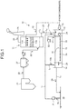
- FIG. 1 is a schematic diagram illustrating a configuration of a seawater desulfurization device according to a first embodiment.
- a seawater desulfurization device 10 (desulfurization device) according to the first embodiment includes a packed tower 11 (flue gas desulfurization absorber), an inlet-side diluting and mixing basin 12, an oxidation basin 13 for performing processing of recovering water quality, and an outlet-side diluting and mixing basin 14.
- a seawater desulfurization device 10 includes a packed tower 11 (flue gas desulfurization absorber), an inlet-side diluting and mixing basin 12, an oxidation basin 13 for performing processing of recovering water quality, and an outlet-side diluting and mixing basin 14.
- seawater 15 used for the packed tower 11 and the seawater 15 used for modifying water quality by the oxidation basin 13 that performs processing of recovering water quality used is seawater after being separately pumped up and used for cooling by a condenser (not illustrated) in a boiler 21, and before being discharged to the sea 16.
- the seawater 15 for dilution is pumped up from the sea 16 by a pump P 11 via a seawater supply line L 1 , and partial seawater 15a is supplied to the inlet-side diluting and mixing basin 12 by the pump P 11 via a seawater supply line L 2 .
- a dilution seawater supply line L 3 is arranged for supplying seawater 15b for dilution to the outlet-side diluting and mixing basin 14 as needed.
- cooled seawater from the condenser (not illustrated) is used, but the present invention is not limited thereto. Seawater that is directly pumped up by the pump P 11 from the sea 16 may be used.
- the packed tower 11 is a tower that brings flue gas 22 from the boiler 21 into gas-liquid contact with the seawater 15 to clean the flue gas 22.
- the packed tower 11 includes a sprinkler device 11A and a filler 11B therein.
- the sprinkler device 11A sprinkles the seawater 15 toward the filler 11B from an upper side in a vertical direction of the filler 11B.
- the seawater 15 passes through the filler 11B.
- the flue gas 22 is supplied to the packed tower 11 from the boiler 21.
- the flue gas 22 is caused to pass through the filler 11B.
- the flue gas 22 is brought into gas-liquid contact with the seawater 15 within the filler 11B, and a sulfur component in the flue gas 22 is absorbed into the seawater 15.
- the sprinkler device 11A may have any configuration that supplies the seawater 15 to the filler 11B from the upper side in the vertical direction of the filler 11B.
- the sprinkler device 11A is arranged on the upper side in the vertical direction of the filler 11B, and sprinkles (jets) the seawater in a vertically downward direction, but the direction in which the seawater is jetted is not limited to the vertically downward direction.
- the direction in which the seawater is jetted (supplied), that is, a traveling direction of the seawater jetted from the sprinkler device 11A is optional so long as the sprinkler device 11A jets (supplies) the seawater to the filler 11B from the upper side in the vertical direction of the filler 11B.
- the packed tower 11 brings the flue gas 22 into gas-liquid contact with the seawater 15 to cause a reaction as represented by the following Equation (1), causes the seawater 15 to absorb sulfur content such as SOx contained in a form of SO 2 and the like in the flue gas 22, and removes the sulfur content in the flue gas 22 using the seawater 15.
- H 2 SO 3 that is generated through gas-liquid contact between the seawater 15 and the flue gas 22 dissociates and a hydrogen ion (H + ) is released into the seawater 15, so that a pH is lowered, and a large amount of sulfur content is absorbed into sulfur content absorption seawater 23.
- the sulfur content absorption seawater 23 contains high-concentration sulfur content.
- the pH of the sulfur content absorption seawater 23 is, for example, about 3 to 6.
- the sulfur content absorption seawater 23 that has absorbed sulfur content in the packed tower 11 is stored in a tower bottom part of the packed tower 11.
- the sulfur content absorption seawater 23 stored in the tower bottom part of the packed tower 11 is supplied to the inlet-side diluting and mixing basin 12 via a sulfur content absorption seawater discharge line L 4 .
- the sulfur content absorption seawater 23 supplied to the inlet-side diluting and mixing basin 12 is mixed with the seawater 15 from the condenser and the seawater 15a for dilution that are supplied to the inlet-side diluting and mixing basin 12 to be diluted, and becomes acidic mixed seawater 24.
- Cleaned gas 25 desulfurized in the packed tower 11 is discharged to the atmosphere through a stack 26.
- a dust collection unit 27 is arranged between the boiler 21 and the packed tower 11, and removes ash dust and the like from the flue gas 22.
- a desulfurization ratio of the flue gas 22 is separately adjusted based on a ratio between inlet SO 2 concentration and outlet SO 2 concentration (outlet SO 2 concentration/inlet SO 2 concentration) in the flue gas 22 supplied to the packed tower 11, and seawater properties of the seawater 15 for desulfurization and the sulfur content absorption seawater 23.
- an SO 2 concentration meter is arranged for measuring inlet SO 2 concentration and outlet SO 2 concentration of the flue gas 22.
- the acidic mixed seawater 24 obtained by mixing the sulfur content absorption seawater 23 with the seawater 15 is supplied to the oxidation basin 13 arranged on a downstream side of the inlet-side diluting and mixing basin 12.
- a diffuser 30 for seawater desulfurization serving as an aeration unit that performs processing of recovering water quality of the acidic mixed seawater 24.
- the diffuser 30 for seawater desulfurization includes an air blower for oxidation 32 serving as an air introduction unit that supplies air 31, an air supply pipe 33 that supplies the air 31, a diffuser tube 34 branched off from the air supply pipe 33, and a hole for jetting for supplying the air 31 to the acidic mixed seawater 24 within the oxidation basin 13.
- the outside air 31 is supplied into the oxidation basin 13 through a hole via the diffuser tube 34 by the air blower for oxidation 32, and oxygen is dissolved as represented by the following Equation (2).
- the sulfur content in the acidic mixed seawater 24 is brought into contact with the air 31 to cause an oxidation reaction of a bisulfite ion (HSO 3 - ) and a decarboxylation reaction of a bicarbonate ion (HCO 3 - ) as represented by the following Equations (3) to (5), and water quality of the acidic mixed seawater 24 is recovered to make water quality recovered seawater 29, which is discharged to the sea 16 via a discharge line L 7 .
- the pH of the acidic mixed seawater 24 can be raised, and chemical oxygen demand (COD) can be reduced. Accordingly, the water quality recovered seawater 29 can be discharged while causing the pH, dissolved oxygen (DO) concentration, and the chemical oxygen demand (COD) of the water quality recovered seawater 29 to be at a level that can be discharged to the sea 16.
- COD chemical oxygen demand
- FIG. 2 is a perspective view of the filler according to the first embodiment.
- FIG. 3 is a cross-sectional view of the filler according to the first embodiment viewed from the direction S in FIG. 2 .
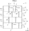
- FIG. 4 is a cross-sectional view of the filler according to the first embodiment viewed from the direction T in FIG. 2 .
- the filler 11B includes a filling unit 40A and a filling unit 40B.
- a direction orthogonal to a direction X as a predetermined direction is assumed to be a direction Y
- a direction orthogonal to the direction X and the direction Y is assumed to be a direction Z.
- the direction Z is a vertical direction
- the direction X and the direction Y are horizontal directions.
- the direction S corresponds to the direction Y
- the direction T corresponds to the direction X.
- the filling unit 40A includes a first filling part 50 and a second filling part 52.
- the first filling part 50 includes an outer frame part 60, a first plate unit 64, and a second plate unit 74.
- the outer frame part 60 includes a first outer frame part 60A and a second outer frame part 60B.
- the first outer frame part 60A is a plate-shaped member extending along the direction Y.
- Two first outer frame parts 60A are opposed to each other in the direction X.
- the second outer frame part 60B is a plate-shaped member extending along the direction X.
- Two second outer frame parts 60B are opposed to each other along the direction Y.
- a space surrounded by the two first outer frame parts 60A and the two second outer frame parts 60B has a rectangular shape.
- the lengths of the first outer frame part 60A and the second outer frame part 60B may be the same, or any of the lengths thereof may be longer.
- the first plate unit 64 includes a plate part 62A.
- the plate part 62A is a plate-shaped member extending in the direction Z from a lower end face 67 as an end face on a lower side along the direction Z (opposite side of the direction Z) to an upper end face 66 as an end face on an upper side along the direction Z (direction Z side).
- the plate part 62A extends toward the direction Y from a side surface 62S as one side surface along the direction Y to the other side surface 62T.
- the side surface 62S is fixed to one of the second outer frame parts 60B
- the side surface 62T is fixed to the other one of the second outer frame parts 60B.
- the upper end face 66 is a face perpendicular to the direction Z, that is, a face parallel with the direction X and the direction Y.
- a thickness of the plate part 62A that is, a length thereof along the direction X becomes smaller from the upper end face 66 toward the lower end face 67.
- the thickness of the plate part 62A at the upper end face 66 that is, the length along the direction X at the upper end face 66 is assumed to be a length L1.
- the thickness of the plate part 62A at the lower end face 67, that is, the length along the direction X at the lower end face 67 is assumed to be L2.
- the length L1 is longer than the length L2 in the plate part 62A. More specifically, the length L1 is preferably 1.5 times or more the length L2.
- the first plate unit 64 a plurality of plate parts 62A described above are arranged at predetermined intervals along the direction X.
- the first plate unit 64 includes four plate parts 62A, but there can be any number of plate parts 62A.
- the second plate unit 74 includes a plate part 72A.
- the plate part 72A is a plate-shaped member extending toward the direction Z from a lower end face 77 as an end face on a lower side along the direction Z (opposite side of the direction Z) to an upper end face 76 as an end face on an upper side along the direction Z (direction Z side).
- the plate part 72A extends while intersecting with (herein, being orthogonal to) the plate part 62A. Specifically, as illustrated in FIG. 2 , the plate part 72A extends in the direction X from a side surface 72S as one side surface along the direction X to the other side surface 72T.
- the side surface 72S is fixed to one of the first outer frame parts 60A
- the side surface 72T is fixed to the other one of the first outer frame parts 60A.
- the upper end face 76 is a face perpendicular to the direction Z, that is, a face parallel with the direction X and the direction Y. As illustrated in FIG. 4 , a thickness of the plate part 72A, that is, a length thereof along the direction Y becomes smaller from the upper end face 76 toward the lower end face 77.
- the thickness of the plate part 72A at the upper end face 76 that is, the length along the direction Y at the upper end face 76 is assumed to be a length L3.
- the thickness of the plate part 72A at the lower end face 77 that is, the length along the direction Y at the lower end face 77 is assumed to be a length L4.
- the length L3 is longer than the length L4 in the plate part 72A. More specifically, the length L3 is preferably 1.5 times or more the length L4.
- the second plate unit 74 a plurality of plate parts 72A described above are arranged at predetermined intervals along the direction Y.
- the second plate unit 74 includes two plate parts 72A, but there can be any number of plate parts 72A.
- the first plate unit 64 and the second plate unit 74 form a grid part 69 as a space surrounded by two plate parts 62A and the two plate parts 72A. Side surfaces of the grid part 69 along the directions X and Y are surrounded by the plate parts 62A and 72A, and both end parts thereof along the direction Z are opened.
- the second filling part 52 includes the outer frame part 60, the first plate unit 64, and the second plate unit 74.
- the first plate unit 64 included in the second filling part 52 includes a plate part 62B.
- a distance from the plate part 62B to the outer frame part 60 (first outer frame part 60A) along the direction X is different from a distance from the plate part 62A included in the first filling part 50 to the outer frame part 60 (first outer frame part 60A) along the direction X.
- the plate part 62B is the same as the plate part 62A in other respects.
- the second plate unit 74 included in the second filling part 52 includes a plate part 72B.
- a distance from the plate part 72B to the outer frame part 60 (second outer frame part 60B) along the direction Y is different from a distance from the plate part 72 included in the first filling part 50 to the outer frame part 60 (second outer frame part 60B) along the direction Y.
- the plate part 72B is the same as the plate part 72A in other respects. That is, in the second filling part 52, the distance from the plate part 62B to the outer frame part 60 along the direction X and the distance from the plate part 72B to the outer frame part 60 along the direction Y are different from those in the first filling part 50.
- the second filling part 52 has the same structure as that of the first filling part 50 in other respects.
- the plate part 62A is not distinguished from the plate part 62B, they are referred to as a plate part 62.
- the plate part 72A is not distinguished from the plate part 72B, they are referred to as a plate part 72.
- the first filling part 50 and the second filling part 52 are stacked along the direction Z.
- a bottom face opposite to the direction Z of the outer frame part 60 of the first filling part 50 is placed over an upper surface on the direction Z side of the outer frame part 60 of the second filling part 52.
- the grid part 69 in the first filling part 50 communicates with the grid part 69 in the second filling part 52.
- the plate part 62B included in the second filling part 52 is arranged at a position shifted from the plate part 62A included in the first filling part 50 in the direction X.
- the plate part 62A is not arranged on an extension line of the plate part 62B along the direction Z.
- the plate part 62B is arranged in a region adjacent, along the direction X, to a region on an extension line of the plate part 62A along the direction Z.
- the plate part 72B included in the second filling part 52 is arranged at a position shifted from the plate part 72A included in the first filling part 50 in the direction Y.
- the plate part 72B is not arranged on an extension line of the plate part 72A along the direction Z.
- the plate part 72B is arranged in a region adjacent, along the direction Y, to a region on an extension line of the plate part 72A along the direction Z.
- plate parts 62 included in the first filling part 50 and the second filling part 52 are arranged at positions shifted from each other in the direction X, and plate parts 72 included in the first filling part 50 and the second filling part 52 are arranged at positions shifted from each other in the direction Y.
- only one group of the plate parts 62 and the plate parts 72 may be arranged at positions shifted from each other.
- the filling unit 40B includes the first filling part 50 and the second filling part 52.
- a method of stacking the first filling part 50 and the second filling part 52 in the filling unit 40B is the same as that in the filling unit 40A. That is, the filling unit 40B has the same structure as that of the filling unit 40A.
- the filling unit 40A and the filling unit 40B are stacked along the direction Z. Specifically, in the filler 11B, a bottom face opposite to the direction Z of the outer frame part 60 of the second filling part 52 included in the filling unit 40A is placed over an upper surface on the direction Z side of the outer frame part 60 of the first filling part 50 included in the filling unit 40B.
- the grid part 69 included in the filling unit 40A communicates with the grid part 69 included in the filling unit 40B.
- the filler 11B includes two filling units 40A and 40B, but there can be any number of filling units.
- the plate parts 62A included in the filling unit 40A are arranged to be located directly above each other in the direction X, and the plate parts 62B included in the filling unit 40B are arranged to be located directly above each other in the direction X.
- the plate part 62A included in the filling unit 40A is arranged on an extension line of the plate part 62A included in the filling unit 40B along the direction Z.
- a position of a center axis A1 along the direction Z of the plate part 62A included in the filling unit 40A is identical to a position of a center axis A2 along the direction Z of the plate part 62A included in the filling unit 40B.
- the plate parts 62B included in the filling unit 40A are arranged to be located directly above each other in the direction X, and the plate parts 62B included in the filling unit 40B are arranged are arranged to be located directly above each other in the direction X.
- the plate part 62B included in the filling unit 40B is arranged on an extension line of the plate part 62B included in the filling unit 40A along the direction Z.
- a position of a center axis A3 along the direction Z of the plate part 62B included in the filling unit 40A is identical to a position of a center axis A4 along the direction Z of the plate part 62B included in the filling unit 40B.
- the plate part 72A included in the filling unit 40A and the plate part 72A included in the filling unit 40B are arranged to be located directly above each other in the direction Y.
- the plate part 72A included in the filling unit 40B is arranged on an extension line of the plate part 72A included in the filling unit 40A along the direction Z.
- a position of a center axis B1 along the direction Z of the plate part 72A included in the filling unit 40A is identical to a position of a center axis B2 along the direction Z of the plate part 72A included in the filling unit 40B.
- the plate part 72B included in the filling unit 40A and the plate part 72B included in the filling unit 40B are arranged to be located directly above each other in the direction Y.
- the plate part 72B included in the filling unit 40B is arranged on an extension line of the plate part 72B included in the filling unit 40A along the direction Z.
- a position of a center axis B3 along the direction Z of the plate part 72B included in the filling unit 40A is identical to a position of a center axis B4 along the direction Z of the plate part 72B included in the filling unit 40B.
- the filler 11B configured as described above is housed in the packed tower 11.
- the filler 11B is filled within the packed tower 11 so that the direction Z becomes a direction along an upper side of the vertical direction.
- the directions X and Y become horizontal directions orthogonal to the vertical direction.
- the upper end face 66 of the plate part 62 becomes an end face on an upper side in the vertical direction
- the upper end face 76 of the plate part 72 becomes an end face on an upper side in the vertical direction.
- the filler attached to the inside of the packed tower 11 is required to enhance gas-liquid contact efficiency.
- the thickness of the plate parts 62 and 72 is reduced toward a lower side in the direction Z (vertical direction).
- a large amount of the seawater 15 sprinkled from an upper side in the vertical direction is rebounded by the plate parts 62 and 72.
- Drops of the seawater 15 are finely distributed by being rebounded. Accordingly, a surface area of the seawater 15 is increased, and when the seawater 15 is rebounded, time during which the seawater 15 remains in the filler 11B is increased.
- gas-liquid contact efficiency can be enhanced.
- the filler 11B is constituted of the plate parts 62 and 72 intersecting with each other, so that the structure thereof is simple. The following specifically describes rebounding of the seawater 15 by the plate parts 62 and 72.
- FIG. 5 is an explanatory diagram for explaining rebounding of the seawater.
- FIG. 5 is a cross-sectional view of the filler 11B viewed from the direction S in FIG. 2 .
- rebounding of seawater W by the plate part 62 is described.
- the plate part 72 exhibits the same effect, so that redundant description will not be repeated.
- the seawater 15 is supplied to the filler 11B from an upper side in the direction Z (vertical direction).
- the upper end face 66 of the plate part 62 on the upper side in the vertical direction has a larger thickness than that of the lower end face 67.
- the seawater 15 tends to easily hit the upper end face 66 rather than a surface 68 of the plate part 62.
- the seawater 15 When hitting the surface 68 extending along the vertical direction, the seawater 15 easily flows vertically downward along the surface 68.
- the upper end face 66 does not extend along the vertical direction, so that the seawater 15 can be easily rebounded when hitting the upper end face 66.
- the filler 11B can increase the rebounding amount of the seawater 15 to enhance gas-liquid contact efficiency.
- the rebounded seawater 15 may hit an adjacent plate part 62 or hit the plate part 62 on a lower side to be further rebounded, and gas-liquid contact efficiency is further enhanced.
- the plate part 62B of the second filling part 52 is arranged on a lower side in the vertical direction of the plate part 62A of the first filling part 50.
- the plate part 62B of the second filling part 52 is arranged at a position shifted from the plate part 62A of the first filling part 50 along the direction X, that is, the horizontal direction.
- the seawater 15A rebounded from the plate part 62A of the first filling part 50 tends to easily hit the upper end face 66 of the plate part 62B of the second filling part 52.
- the seawater 15 tends to be rebounded more easily, and gas-liquid contact efficiency can be further enhanced.
- the plate part 62A included in the filling unit 40B is arranged on a lower side in the vertical direction of the plate part 62A included in the filling unit 40A.
- the plate part 62A included in the filling unit 40B is arranged to be located directly above the plate part 62A included in the filling unit 40A in the direction X. That is, the plate part 62A included in the filling unit 40B is arranged on an extension line on a lower side in the vertical direction of the plate part 62A included in the filling unit 40A.
- the seawater 15B flowing on the surface 68 of the plate part 62A included in the filling unit 40A concentrates in a center direction of the plate part 62A along the surface 68 as flowing vertically downward, and is dropped onto the plate part 62A included in the filling unit 40B.
- the seawater 15B hits the upper end face 66 of the plate part 62A included in the filling unit 40B.
- the seawater 15 tends to be rebounded more easily, and gas-liquid contact efficiency can be further enhanced.
- the seawater 15 is brought into gas-liquid contact with the flue gas 22, but the embodiment is not limited thereto. Water may be used in place of the seawater.
- the filler 11B is a filler for the packed tower 11 that is arranged inside the packed tower 11, causes water to pass therethrough when the water is sprinkled from an upper side in the vertical direction, causes the flue gas 22 to pass therethrough, and brings the flue gas 22 into contact with the water to be desulfurized.
- the filler 11B includes the first plate unit 64 and the second plate unit 74.
- the first plate unit 64 includes a plurality of plate parts 62 that extend in the direction Z (vertical direction), and are arranged at predetermined intervals.
- the second plate unit 74 includes a plurality of plate parts 72 that intersect with the plate part 62 of the first plate unit 64, extend in the direction Z (vertical direction), and are arranged at predetermined intervals.
- the second plate unit 74 forms, together with the first plate unit 64, the grid part 69 both end faces of which along the direction Z (vertical direction) are opened.
- the thickness of the plate part 62 is reduced from the upper end face 66 in the direction Z (vertical direction) toward the lower end face 67 in the direction Z (vertical direction).
- the filler 11B is constituted of the plate parts 62 and 72.
- the filler 11B has a simple structure.
- the thickness of the upper end face 66 on the upper side in the vertical direction is larger than that of the lower end face 67.
- the filler 11B can increase the rebounding amount of the seawater 15 to enhance gas-liquid contact efficiency.
- the upper end face 66 as an end face on the upper side in the direction Z (vertical direction) is perpendicular to the direction Z (vertical direction).
- the seawater 15 supplied from the upper side in the vertical direction tends to flow along the surface.
- the hitting surface becomes nearly perpendicular to the vertical direction, the seawater 15 supplied from the upper side in the vertical direction tends to be rebounded more easily.
- the upper end face 66 is a face perpendicular to the vertical direction, so that the rebounding amount of the seawater 15 can be increased, and gas-liquid contact efficiency can be enhanced more appropriately.
- the plate parts 62 and 72 may include groove parts 66A and 76A on the upper end faces 66 and 76.
- FIG. 6 and FIG. 7 are schematic diagrams illustrating another example of the plate part according to the first embodiment.
- the groove part 66A (76A) may have a V-shape in which two planes intersect with each other forming an angle ⁇ 1 as illustrated in FIG. 6 , or may be formed with a curved surface as illustrated in FIG. 7 .
- the groove part 66A can increase the rebounding amount of the seawater 15, and enhance gas-liquid contact efficiency more appropriately.
- the angle ⁇ 1 is preferably equal to or larger than 90 degrees and smaller than 180 degrees.
- the first filling part 50 and the second filling part 52 are stacked along the direction Z (vertical direction).
- the plate part 62B of the first plate unit 64 included in the second filling part 52 is arranged at a position shifted from the position of the plate part 62A of the first plate unit 64 included in the first filling part 50 in the horizontal direction (direction X) perpendicular to the vertical direction.
- the filler 11B can cause the seawater 15A rebounded from the plate part 62A of the first filling part 50 to easily hit the plate part 62B of the second filling part 52.
- the filler 11B can further enhance gas-liquid contact efficiency.
- a plurality of filling units including the first filling part 50 and the second filling part 52 are stacked along the vertical direction (direction Z).
- the plate parts 62A included in the first plate unit 64 of the first filling part 50 are arranged to be located directly above each other in the horizontal direction (direction X).
- the plate parts 62B included in the first plate unit 64 of the second filling part 52 are arranged to be located directly above each other in the horizontal direction.
- the filler 11B facilitates causing the seawater 15B flowing on the surface 68 of the plate part 62 to be dropped onto the plate part 62 included in the filling unit 40B.
- the filler 11B can further enhance gas-liquid contact efficiency.
- a filler 11Ba according to the second embodiment is different from that in the first embodiment in that the plate part includes a projection part. Description about the same configuration in the second embodiment as that in the first embodiment will not be repeated.
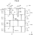
- FIG. 8 and FIG. 9 are cross-sectional views of the filling part according to the second embodiment.
- a first plate unit 64a of the first filling part 50 according to the second embodiment includes a plate part 62Aa.
- the first plate unit 64a of the second filling part 52 according to the second embodiment includes a plate part 62Ba.
- the plate part 62Aa and the plate part 62Ba that is, a plate part 62a has a constant thickness from an upper end face 66a toward a lower end face 67a. That is, surfaces 68a on both sides along the direction X of the plate part 62a are along the direction Z (vertical direction).
- the plate part 62a includes a projection part 80A on each of the surfaces 68a on both sides.
- the projection part 80A extends from one side surface 62S to the other side surface 62T (refer to FIG. 2 ) of the plate part 62a in a direction away from the surface 68a. More specifically, the projection part 80A of the surface 68a on the direction X side extends toward the direction X, and the projection part 80A of the surface 68a on an opposite side of the direction X extends toward a direction opposite to the direction X.
- the projection part 80A includes an upper surface 82A as a surface on the direction Z side (a surface on the upper side in the vertical direction), and a lower surface 84A as a surface opposite to the direction Z (a surface on the lower side in the vertical direction).
- the upper surface 82A is a surface perpendicular to the direction Z (vertical direction). That is, an angle ⁇ 2 between the upper surface 82A and the direction Z (vertical direction) is 90 degrees. However, the angle ⁇ 2 may be equal to or larger than 90 degrees and smaller than 180 degrees, and is more preferably equal to or larger than 90 degrees and smaller than 120 degrees.
- the lower surface 84A as a surface opposite to the direction Z of the projection part 80A (a surface on the lower side in the vertical direction) is also a surface perpendicular to the direction Z (vertical direction).
- the projection part 80A is arranged at the upper end face 66a of the plate part 62a, that is, arranged at an end part on the direction Z side of the plate part 62a.
- the thickness of the plate part 62a, that is, the length along the direction X is assumed to be a length L5.
- the height of the plate part 62a, that is, the length along the direction Z is assumed to be a length L6.
- the width of the projection part 80A, that is, the length along the direction X is assumed to be a length L7.
- the height of the projection part 80A, that is, the length along the direction Z is assumed to be a length L8.
- the length L5 is equal to or larger than 1 mm and equal to or smaller than 5 mm.
- the length L6 is equal to or larger than 5 cm and equal to or smaller than 30 cm.
- the length L7 is equal to or larger than 1.5 mm and equal to or smaller than 50 mm, and is preferably equal to or larger than 1.5 times the length L5 and equal to or smaller than 10 times the length L5.
- the length L8 is equal to or larger than 1 mm and equal to or smaller than 5 cm.
- the lengths L5, L6, L7, and L8 are not limited to a value in this numerical range.
- a second plate unit 74a of the first filling part 50 according to the second embodiment includes a plate part 72Aa.
- the second plate unit 74a of the second filling part 52 according to the second embodiment includes a plate part 72Ba.
- the plate part 72Aa and the plate part 72Ba that is, a plate part 72a has a constant thickness from an upper end face 76a toward a lower end face 77a. That is, surfaces 78a on both sides along the direction Y of the plate part 72a are along the direction Z (vertical direction).
- the plate part 72a includes a projection part 80B on each of the surfaces 78a on both sides.
- the projection part 80B extends from one side surface 72S to the other side surface 72T (refer to FIG.
- the projection part 80B of the surface 78a on the direction Y side extends toward the direction Y
- the projection part 80B of the surface 78a on an opposite side of the direction Y extends toward a direction opposite to the direction Y.
- the projection part 80B includes an upper surface 82B as a surface on the direction Z side (a surface on the upper side in the vertical direction), and a lower surface 84B as a surface opposite to the direction Z (a surface on the lower side in the vertical direction).
- the upper surface 82B is a surface perpendicular to the direction Z (vertical direction). That is, an angle ⁇ 3 between the upper surface 82B and the direction Z (vertical direction) is 90 degrees. However, the angle ⁇ 3 may be equal to or larger than 90 degrees and smaller than 180 degrees.
- the lower surface 84B is also a surface perpendicular to the direction Z (vertical direction).
- the projection part 80B is arranged at the upper end face 76a of the plate part 72a, that is, arranged at an end part on the direction Z side of the plate part 72a.
- the thickness of the plate part 72a that is, the length along the direction Y is assumed to be a length L9.
- the height of the plate part 72a, that is, the length along the direction Z is assumed to be a length L10.
- the width of the projection part 80B, that is, the length along the direction Y is assumed to be a length L11.
- the height of the projection part 80B, that is, the length along the direction Z is assumed to be a length L12.
- the length L9 is equal to or larger than 1 mm and equal to or smaller than 5 mm.
- the length L10 is equal to or larger than 5 cm and equal to or smaller than 30 cm.
- the length L11 is equal to or larger than 1.5 mm and equal to or smaller than 50 mm, and is preferably equal to or larger than 1.5 times the length L5 and equal to or smaller than 10 times the length L5.
- the length L12 is equal to or larger than 1 mm and equal to or smaller than 5 cm.
- the lengths L9, L10, L11, and L12 are not limited to a value in this numerical range.
- the filler 11Ba according to the second embodiment includes the projection parts 80A and 80B, so that the filler 11Ba can enhance gas-liquid contact efficiency with a simple structure similarly to the filler 11B according to the first embodiment.
- the projection part 80A of the plate part 62a projects from the surface 68a of the plate part 62a along the direction X.
- the angle between the upper surface 82A of the projection part 80A and the direction Z (vertical direction) is equal to or larger than 90 degrees and smaller than 180 degrees. In this way, the projection part 80A projects from the plate part 62a.
- the seawater 15 tends to easily hit the upper surface 82A of the projection part 80A rather than the surface 68a of the plate part 62a.
- the upper surface 82A of the projection part 80A forms an angle equal to or larger than 90 degrees and smaller than 180 degrees with respect to the vertical direction.
- the seawater 15 tends to be easily rebounded when hitting the upper surface 82A.
- the rebounded seawater 15 tends to easily hit the plate part 62Ba of the second filling part 52 at a position shifted along the direction Y.
- the filler 11Ba includes the projection part 80A, so that the rebounding amount of the seawater 15 can be increased, and gas-liquid contact efficiency can be enhanced.
- the projection part 80B has the same effect as that of the projection part 80A.
- the filler 11Ba may include at least one of the projection parts 80A and 80B.
- the filler 11Ba is a filler for the packed tower 11 that is arranged inside the packed tower 11, causes water to pass therethrough when the water is sprinkled from an upper side in the vertical direction, causes the flue gas 22 to pass therethrough, and brings the flue gas 22 into contact with the water to be desulfurized.
- the filler 11B includes the first plate unit 64 and the second plate unit 74.
- the first plate unit 64 includes a plurality of plate parts 62a that extend in the direction Z (vertical direction), and are arranged at predetermined intervals.
- the second plate unit 74 includes a plurality of plate parts 72a that intersect with the plate part 62 of the first plate unit 64, extend in the direction Z (vertical direction), and are arranged at predetermined intervals.
- the second plate unit 74 forms, together with the first plate unit 64, the grid part 69 both end faces of which along the direction Z (vertical direction) are opened.
- the plate part 62a includes the projection part 80A.
- the projection part 80A extends in a direction away from the surface 68a from one side part (side surface 62S) to the other side part (side surface 62T) of the plate part 62a on both surfaces 68a extending in the direction Z (vertical direction).
- the angle between the surface on the upper side in the vertical direction (upper surface 82A) of the projection part 80A and the vertical direction (direction Z) is equal to or larger than 90 degrees and smaller than 180 degrees.
- the projection part 80A can increase the rebounding amount of the seawater 15 and enhance gas-liquid contact efficiency.
- the projection part 80A is arranged at the upper end face 66a in the vertical direction of the plate part 62a.
- the filler 11Ba can cause a larger amount of seawater 15 to hit the projection part 80A, and the rebounding amount can be increased to enhance gas-liquid contact efficiency more appropriately.
- the projection part 80A according to the second embodiment is arranged on the upper end face 66a side of the plate part 62a, and the upper surface 82A and the lower surface 84A are perpendicular to the direction Z.
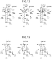
- FIGS. 10 to 12 are diagrams illustrating another configuration example of the projection part according to the second embodiment.
- the following describes another example of the projection part 80A.
- the projection part 80B can have the same shape as that of the projection part 80A, so that the description thereof is omitted.
- the projection part 80A can be at any position in the direction Z so long as the projection part 80A is arranged on the surface 68a of the plate part 62a.
- the projection part 80A may be arranged between the upper end face 66a and the lower end face 67a.
- the projection part 80A may be arranged at the lower end face 67a.
- the lower surface 84A of the projection part 80A may be tilted toward the direction Z (upper side in the vertical direction) from a terminal part 84S connected to the plate part 62a toward a distal end part 84T. Due to this, the seawater 15 flowing along the projection part 80A can be caused to flow toward the center, and the seawater 15 can be caused to appropriately hit the plate part 62a immediately below in the vertical direction.
- the lower surface 84A may be a plane tilted toward the direction Z.
- the lower surface 84A may be a curved surface bulging toward a direction opposite to the direction Z.
- the upper surface 82A of the projection part 80A may be tilted toward the direction Z (upper side in the vertical direction) from a terminal part 82S connected to the plate part 62a toward a distal end part 82T.
- the projection part 80A can increase the rebounding amount of the seawater 15 to enhance gas-liquid contact efficiency more appropriately.
- An angle ⁇ 4 between the upper surface 82A and the surface 68a of the plate part 62a is preferably equal to or larger than 60 degrees and smaller than 90 degrees. For example, as illustrated in (A) of FIG.
- the lower surface 84A may be a plane tilted toward the direction Z, or a curved surface bulging toward a direction opposite to the direction Z. As illustrated in (B) and (C) of FIG. 12 , the lower surface 84A may also be tilted in the direction Z in addition to the upper surface 82A.
- FIG. 13 is a schematic diagram illustrating another example of the plate part according to the second embodiment. As illustrated in (A) of FIG. 13 , the thickness of the plate part 62a may be reduced from an upper part in the direction Z (vertical direction) (upper end face 66a) toward a lower part in the direction Z (vertical direction) (lower end face 67a). That is, the plate part 62a in (A) of FIG. 13 is the plate part 62a according to the first embodiment. In other words, the plate part 62 (72) according to the first embodiment may include the projection part 80A (80B) according to the second embodiment.
- the thickness of the plate part 62a may be increased from the upper end face 66a toward an intermediate part 66a1, and the thickness thereof may be reduced from the intermediate part 66a1 toward the lower end face 67a.
- the intermediate part 66a1 is an optional position between the upper end face 66a and the lower end face 67a of the plate part 62a.
- the thickness of the plate part 62a may be increased from the upper end face 66a toward the lower end face 67a.
- a filler 11Bb according to the third embodiment is different from that in the first embodiment in that the filler 11Bb includes an opening plate part 90. Description about the same configuration in the third embodiment as that in the first embodiment will not be repeated.
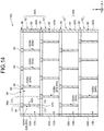
- FIGS. 14 and 15 are cross-sectional views of the filling part according to the third embodiment.
- FIG. 16 is a top view of the filling part according to the third embodiment.
- a first plate unit 64b of the first filling part 50 according to the third embodiment includes a plate part 62Ab.
- the first plate unit 64b of the second filling part 52 according to the third embodiment includes a plate part 62Bb.
- the plate part 62Ab and the plate part 62Bb that is, a plate part 62b has a constant thickness from an upper end face 66b toward a lower end face 67b. That is, surfaces 68b on both sides along the direction X of the plate part 62b are along the direction Z (vertical direction).
- a second plate unit 74b of the first filling part 50 according to the third embodiment includes a plate part 72Ab.
- a second plate unit 74b of the second filling part 52 according to the third embodiment includes a plate part 72Bb.
- the plate part 72Ab and the plate part 72Bb that is, a plate part 72b has a constant thickness from an upper end face 76b toward a lower end face 77b. That is, surfaces 78b on both sides along the direction Y of the plate part 72b are along the direction Z (vertical direction).
- the filler 11Bb includes the opening plate part 90.
- the opening plate part 90 includes an outer frame part 92, a first thin plate unit 95, and a second thin plate unit 97.
- the outer frame part 92 includes a first outer frame part 92A and a second outer frame part 92B.
- the first outer frame part 92A is a plate-shaped member extending along the direction Y.
- Two first outer frame parts 92A are opposed to each other in the direction X.
- the second outer frame part 92B is a plate-shaped member extending along the direction X.
- Two second outer frame parts 92B are opposed to each other along the direction Y.
- a space surrounded by the two first outer frame parts 92A and the two second outer frame parts 92B has a rectangular shape.
- the length of the first outer frame part 92A along the direction Y is the same as that of the first outer frame part 60A of the first filling part 50 (refer to FIG. 2 ).
- the length along the direction X of the second outer frame part 92B is the same as that of the second outer frame part 60B of the first filling part 50 (refer to FIG. 2 ).
- the first thin plate unit 95 includes a thin plate part 94.
- the thin plate part 94 is a plate-shaped member extending along the direction Y from one of the second outer frame parts 92B to the other one of the second outer frame parts 92B. Surfaces on both sides of the thin plate part 94 along the direction Z side are planes, which are perpendicular to the direction Z.
- a length L13 along the direction X of the thin plate part 94 is longer than the thickness (length) along the direction X of the plate part 62b.
- the length L13 is equal to or larger than 1.5 mm and equal to or smaller than 50 mm
- the length L14 is equal to or larger than 1.5 mm and equal to or smaller than 50 mm.
- a plurality of thin plate parts 94 are arranged at predetermined intervals along the direction X.
- the number of thin plate parts 94 is the same as the number of plate parts 62b.
- the second thin plate unit 97 includes a thin plate part 96.
- the thin plate part 96 is a plate-shaped member extending along the direction X from one of the first outer frame parts 92A to the other one of the first outer frame parts 92A. Surfaces on both sides of the thin plate part 96 along the direction Z side are planes, which are perpendicular to the direction Z.
- a length L15 along the direction Y of the thin plate part 96 is longer than the thickness (length) along the direction Y of the plate part 72b.
- the length L15 is equal to or larger than 1.5 mm and equal to or smaller than 50 mm
- the length L16 is equal to or larger than 1.5 mm and equal to or smaller than 50 mm.
- the second thin plate unit 97 a plurality of thin plate parts 96 are arranged at predetermined intervals along the direction Y.
- the number of thin plate parts 96 is the same as the number of plate parts 72b.
- the first thin plate unit 95 and the second thin plate unit 97 form an opening 99 as a space surrounded by two thin plate parts 94 and two thin plate parts 96.
- the opening 99 side surfaces along the directions X and Y are surrounded by the thin plate parts 94 and 96, and both end parts along the direction Z are opened.
- the opening plate part 90 is a plate-shaped member having a plane surface perpendicular to the direction Z, and it can be said that a plurality of openings 99 penetrate the surface in a grid-like fashion (two-dimensional matrix). As illustrated in FIG. 14 and FIG. 15 , the length along the direction Z of the opening plate part 90 is shorter than the length along the direction Z of the plate parts 62 and 72. In other words, the length along the direction Z of the opening plate part 90 is shorter than the length along the direction Z of the first filling part 50, and shorter than the length along the direction Z of the second filling part 52.
- the number of openings 99 is the same as the number of grid parts 69 included in the first filling part 50, and the number of grid parts 69 included in the second filling part 52.
- a pitch of the opening 99 is the same as a pitch of the grid part 69. That is, a distance between center axes along the direction Z of adjacent openings 99 is the same as a distance between center axes along the direction Z of adjacent grid parts 69. However, the length along the direction X and the direction Y of the opening 99 is shorter than the length along the direction X and the direction Y of the grid part 69.
- a plurality of opening plate parts 90 described above are stacked along the direction Z together with the first filling part 50 and the second filling part 52.
- the opening plate part 90 is arranged on the direction Z side (upper side in the vertical direction) of the first filling part 50.
- the opening plate part 90 is also arranged between the first filling part 50 and the second filling part. That is, the first filling part 50 and the second filling part 52 are stacked along the vertical direction with the opening plate part 90 interposed therebetween.
- the filling unit 40A and the filling unit 40B are stacked along the vertical direction with the opening plate part 90 interposed therebetween.
- the thin plate part 94 of the opening plate part 90 is arranged on the upper end face 66b of the plate part 62b adjacent to the opposite side of the direction Z.
- the plate part 62b included in the first filling part 50 or the second filling part 52 adjacent to the opening plate part 90 on the opposite side of the direction Z (lower side in the vertical direction) is referred to as a first adjacent plate part.
- the thin plate part 94 included in the opening plate part 90 and the first adjacent plate part are arranged to be located directly above each other in the direction X.
- the first adjacent plate part is arranged on an extension line of the thin plate part 94 along the direction Z.
- a position of a center axis C1 along the direction Z of the thin plate part 94 is identical to that of a center axis C2 of the first adjacent plate part.
- a center axis of the opening 99 of the opening plate part 90 is assumed to be a center axis C3, and a center axis of the grid part 69 formed by the first filling part 50 or the second filling part 52 adjacent to the opposite side of the direction Z (lower side in the vertical direction) of the opening plate part 90 is assumed to be a center axis C4.
- a position of the center axis C3 is identical to that of the center axis C4.
- the opening 99 communicates with the grid part 69.
- the thin plate part 96 of the opening plate part 90 is arranged on the upper end face 76b of the plate part 72b adjacent to the opposite side of the direction Z.
- the plate part 72b included in the first filling part 50 or the second filling part 52 adjacent to the opening plate part 90 on the opposite side of the direction Z (lower side in the vertical direction) is referred to as a second adjacent plate part.
- the thin plate part 96 included in the opening plate part 90 and the second adjacent plate part are arranged to be located directly above each other in the direction Y.
- the second adjacent plate part is arranged on an extension line of the thin plate part 96 along the direction Z.
- a position of a center axis D1 along the direction Z of the thin plate part 96 is identical to that of a center axis D2 of the second adjacent plate part.
- the filler 11Bb is a filler for the packed tower 11 that is arranged inside the packed tower 11, causes water to pass therethrough when the water is sprinkled from an upper side in the vertical direction, causes the flue gas 22 to pass therethrough, and brings the flue gas 22 into contact with the water to be desulfurized.
- the filler 11Bb includes the first filling part 50, the second filling part 52, and the opening plate part 90.
- the opening plate part 90 is a plate-shaped member having a plane surface, and a plurality of openings 99 are opened on the surface thereof in a grid-like fashion.
- the first filling part 50 and the second filling part 52 are stacked along the direction Z (vertical direction) with the opening plate part 90 interposed therebetween.
- a distance between center axes of adjacent openings 99 is equal to a distance between center axes of adjacent grid parts 69.
- the thickness between a side surface of the opening 99 and a side surface of the adjacent opening 99, that is, the length L13 of the thin plate part 94 is larger than the thickness of the plate part 62b, that is, the length L14.
- the length L13 of the thin plate part 94 is longer than the length L14 of the plate part 62b.
- the pitch of the opening 99 (distance between the center axes) is equal to the pitch of the grid part 69.
- the seawater 15 tends to easily hit the opening plate part 90, so that the filler 11Bb can increase the rebounding amount of the seawater 15 to enhance gas-liquid contact efficiency.
- gas-liquid contact efficiency can be efficiently enhanced with a simple structure.
- the length along the direction Z (vertical direction) of the opening plate part 90 is shorter than the length along the vertical direction of the first filling part 50 and the second filling part 52. That is, in the filler 11Bb, the opening plate parts 90 having a small thickness and a simple structure are stacked. Thus, with the filler 11Bb, gas-liquid contact efficiency can be efficiently enhanced with a simpler structure.
- the center axis C3 of the opening 99 is identical to the center axis C4 of the grid part 69 of the first filling part 50 or the second filling part 52 adjacent to the opposite side of the direction Z (lower side in the vertical direction).
- the thin plate part 94 is arranged to cover the upper side in the vertical direction of the plate part 62b.
- FIG. 17 is a diagram illustrating another example of the filler according to the third embodiment.
- the position of the center axis C3 of the opening 99 may be shifted from that of the center axis C4 of the grid part 69 of the first filling part 50 or the second filling part 52 adjacent to the opposite side of the direction Z (lower side in the vertical direction).
- the thin plate part 94 is arranged at a position shifted from the plate part 62b in the direction X.
- the seawater 15A that has hit the thin plate part 94 tends to easily hit the upper end face 66b of the plate part 62b.
- the filler 11Bb can increase the rebounding amount of the seawater 15 to enhance gas-liquid contact efficiency.
- the opening plate part 90 according to the third embodiment may be attached to the filler 11B according to the first embodiment and the filler 11Ba according to the second embodiment using the same method.
- the embodiments of the present invention have been described above. However, the embodiments are not limited thereto.
- the components described above include a component that is easily conceivable by those skilled in the art, substantially the same component, and what is called an equivalent.
- the components described above can also be appropriately combined with each other.
- the components can be variously omitted, replaced, or modified without departing from the gist of the embodiments described above.
- the filler 11B (the first filling part 50 and the second filling part 52) according to the first embodiment includes the outer frame part 60 (the first outer frame part 60A and the second outer frame part 60B), but does not necessarily include the outer frame part 60.
- the filler 11B members in which the first plate unit 64 intersects with the second plate unit 74 (the first filling part 50 and the second filling part 52) are stacked.
- the filler 11Ba according to the second embodiment and the filler 11Bb according to the third embodiment do not necessarily include the outer frame part 60.
- the opening plate part 90 according to the third embodiment does not necessarily include the outer frame part 92 (the first outer frame part 92A and the second outer frame part 92B).
Landscapes
- Chemical & Material Sciences (AREA)
- Engineering & Computer Science (AREA)
- Chemical Kinetics & Catalysis (AREA)
- Oil, Petroleum & Natural Gas (AREA)
- Analytical Chemistry (AREA)
- General Chemical & Material Sciences (AREA)
- Environmental & Geological Engineering (AREA)
- Biomedical Technology (AREA)
- Health & Medical Sciences (AREA)
- Physics & Mathematics (AREA)
- Thermal Sciences (AREA)
- Organic Chemistry (AREA)
- Treating Waste Gases (AREA)
- Gas Separation By Absorption (AREA)
- Physical Or Chemical Processes And Apparatus (AREA)
Abstract
Description
- The present invention relates to a filler for a packed tower and a seawater desulfurization device. Background
- In recent years, a thermal power station that is provided with a seawater desalination plant has been increasing. A desulfurization device is also provided to remove sulfur content contained in flue gas that is generated when fossil fuel such as coal is burned. Seawater desulfurization for performing desulfurization by utilizing seawater as an absorbent has been attracting attention from a viewpoint that a power plant and the like are built at a place on the sea front in many cases because a large amount of coolant water is required, and operation cost for desulfurization processing can be kept low. The seawater desulfurization device using seawater as an absorbent is used in a thermal power station and the like because cost thereof is lower than that of a limestone-gypsum method.
- For example, as disclosed in
Patent Literature 1, the seawater desulfurization device includes a flue gas desulfurization absorber (packed tower). The flue gas desulfurization absorber is a tower in which a porous filler is arranged. The flue gas desulfurization absorber distributes seawater from an upper side in a vertical direction of the filler to cause the seawater to pass through the filler. The flue gas desulfurization absorber causes the flue gas to pass through the filler. Accordingly, the seawater and the flue gas are brought into gas-liquid contact with each other inside the filler, and the sulfur content in the flue gas is absorbed into the seawater. - Patent Literature 1: Japanese Patent No.
5754877 - The filler is required to reduce an amount of absorbent (seawater) while securing a desulfurization amount by enhancing gas-liquid contact efficiency. The gas-liquid contact efficiency can be enhanced by increasing a surface area of the filler, but the filler is required to have a complicated shape in this case. Accordingly, production cost may be increased, or a pressure loss may be increased.
- The present invention has been made in view of such a situation, and an object of the present invention is to provide a filler for a packed tower and a seawater desulfurization device for preventing the gas-liquid contact efficiency from being lowered with a simple structure.
- To solve the problem described above and achieve the object, a filler according to this disclosure is for a packed tower that causes water to pass through the filler when the water is sprinkled from an upper side in a vertical direction, and causes flue gas to pass through the filler, to bring the flue gas into contact with the water to desulfurize the flue gas. The filler is arranged inside the packed tower, and includes a first plate unit including a plurality of plate parts that extend in the vertical direction and are arranged at predetermined intervals; and a second plate unit including a plurality of plate parts that intersect with the plate parts of the first plate unit, extend in the vertical direction, and are arranged at predetermined intervals, the second plate unit forming, together with the first plate unit, a grid part both end parts of which along the vertical direction are opened. A thickness of each plate part is reduced from an upper end face in the vertical direction toward a lower end face.
- The filler is constituted of the first plate unit and the second plate unit as a simple structure. A thickness of the filler at the upper end face is larger than a thickness thereof at the lower end face. Thus, the filler can increase a rebounding amount of water to enhance gas-liquid contact efficiency.
- In the filler, an end face of the plate part on an upper side in the vertical direction is preferably perpendicular to the vertical direction. The end face on the upper side in the vertical direction of the filler is perpendicular to the vertical direction, so that the rebounding amount of water can be increased, and the gas-liquid contact efficiency can be enhanced more appropriately.
- In the filler, the plate part preferably includes a groove part on an end face on an upper side in the vertical direction. The filler has a groove part on the end face on the upper side in the vertical direction, so that the rebounding amount of water can be increased, and the gas-liquid contact efficiency can be enhanced more appropriately.
- In the filler, it is preferable that a first filling part including the first plate unit and the second plate unit, and a second filling part including the first plate unit and the second plate unit are stacked along the vertical direction, and a plate part of the first plate unit included in the second filling part is arranged at a position shifted from a position of a plate part of the first plate unit included in the first filling part in a horizontal direction perpendicular to the vertical direction. The filler can cause water rebounded from the plate part of the first filling part to easily hit the plate part of the second filling part. Thus, the filler can further enhance the gas-liquid contact efficiency.
- In the filler, it is preferable that a plurality of filling units each including the first filling part and the second filling part are stacked along the vertical direction, and in the filling units adjacent to each other along the vertical direction, plate parts included in the first plate unit of the first filling part are arranged to be located directly above each other in the horizontal direction, and plate parts included in the first plate unit of the second filling part are arranged to be located directly above each other in the horizontal direction. The filler facilitates causing water flowing on the surface of the plate part to be dropped onto the plate part included in the filling unit on a lower side in the vertical direction. Thus, the filler can further enhance the gas-liquid contact efficiency.
- In the filler, the plate part preferably includes a projection part on each of surfaces extending in the vertical direction, the projection part extending from one side surface to the other side surface of the plate part in a direction away from the surface. The filler has a projection part, so that the gas-liquid contact efficiency can be further enhanced.
- To solve the problem described above and achieve the object, a filler according to this disclosure is for a packed tower that causes water to pass through the filler when the water is sprinkled from an upper side in a vertical direction, and causes flue gas to pass through the filler, to bring the flue gas into contact with the water to desulfurize the flue gas. The filler is arranged inside the packed tower, and includes a first plate unit including a plurality of plate parts that extend in the vertical direction and are arranged at predetermined intervals; and a second plate unit including a plurality of plate parts that intersect with the plate parts of the first plate unit, extend in the vertical direction, and are arranged at predetermined intervals, the second plate unit forming, together with the first plate unit, a grid part both end parts of which along the vertical direction are opened. The plate part includes a projection part on each of surfaces extending in the vertical direction, the projection part extending from one side part to the other side part of the plate part in a direction away from the surface. An angle between an upper surface of the projection part in the vertical direction and the vertical direction is equal to or larger than 90 degrees and smaller than 180 degrees.
- The filler can enhance the gas-liquid contact efficiency with a simple structure by increasing a rebounding amount of water by the projection part.
- In the filler, the projection part is preferably arranged on an upper end face of the plate part in the vertical direction. Thus, the filler can cause a larger amount of water to hit the projection part, so that the rebounding amount can be increased, and the gas-liquid contact efficiency can be enhanced more appropriately.
- In the filler, a lower surface of the projection part in the vertical direction is preferably tilted upward in the vertical direction from a terminal part connected to the plate part toward a distal end part.
- To solve the problem described above and achieve the object, a filler according to this disclosure is for a packed tower that causes water to pass through the filler when the water is sprinkled from an upper side in a vertical direction, and causes flue gas to pass through the filler, to bring the flue gas into contact with the water to desulfurize the flue gas. The filler is arranged inside the packed tower, and includes a first filling part that includes a first plate unit including a plurality of plate parts that extend in the vertical direction and are arranged at predetermined intervals, and a second plate unit including a plurality of plate parts that intersect with the plate parts of the first plate unit, extend in the vertical direction, and are arranged at predetermined intervals, the second plate unit forming, together with the first plate unit, a grid part both end parts of which along the vertical direction are opened; a second filling part that includes the first plate unit and the second plate unit; and an opening plate part as a plate-shaped member having a plane surface in which a plurality of openings penetrate in a grid-like fashion. The first filling part and the second filling part are stacked along the vertical direction across the opening plate part. A distance between center axes of the openings adjacent to each other is equal to a distance between center axes of grid parts adjacent to each other, and a thickness between a side surface of the opening and a side surface adjacent to the opening is larger than a thickness of the plate part.
- In the filler, the thickness between the openings of the opening plate part is larger than the thickness of the plate part. In the filler, a pitch of the opening (a distance between center axes) is equal to a pitch of the grid part. Thus, in the filler, water can easily hit the opening plate part, so that the rebounding amount of water can be increased, and the gas-liquid contact efficiency can be enhanced with a simpler structure.
- In the filler, a length of the opening plate part along the vertical direction is preferably shorter than a length of the first filling part and the second filling part along the vertical direction. In the filler, opening plate parts having a small thickness and a simple structure are stacked. Thus, the filler can efficiently enhance the gas-liquid contact efficiency with a simpler structure.
- In the filler, the center axis of the opening in the opening plate part is preferably identical to the center axis of the grid part of the first filling part or the second filling part adjacent to the opening on a lower side in a vertical direction. In the filler, water can easily hit the opening plate part, so that the rebounding amount of water can be increased, and the gas-liquid contact efficiency can be enhanced.
- In the filler, the center axis of the opening in the opening plate part is preferably arranged to be shifted from a position of the center axis of the grid part of the first filling part or the second filling part adjacent to the opening on a lower side in a vertical direction. In the filler, water can easily hit the opening plate part, so that the rebounding amount of water can be increased, and the gas-liquid contact efficiency can be enhanced.
- To solve the above problems and achieve the object, the desulfurization device for flue gas according to the present disclosure includes the filler for a packed tower. The desulfurization device includes the filler, so that the gas-liquid contact efficiency can be enhanced with a simple structure.
- According to the present invention, gas-liquid contact efficiency can be prevented from being lowered with a simple structure.
-
-
FIG. 1 is a schematic diagram illustrating a configuration of a seawater desulfurization device according to a first embodiment. -
FIG. 2 is a perspective view of a filler according to the first embodiment. -
FIG. 3 is a cross-sectional view of the filler according to the first embodiment viewed from the direction S inFIG. 2 . -
FIG. 4 is a cross-sectional view of the filler according to the first embodiment viewed from the direction T inFIG. 2 . -
FIG. 5 is an explanatory diagram for explaining rebounding of seawater. -
FIG. 6 is a schematic diagram illustrating another example of a plate part according to the first embodiment. -
FIG. 7 is a schematic diagram illustrating another example of the plate part according to the first embodiment. -
FIG. 8 is a cross-sectional view of a filling part according to a second embodiment. -
FIG. 9 is a cross-sectional view of the filling part according to the second embodiment. -
FIG. 10 is a diagram illustrating another configuration example of a projection part according to the second embodiment. -
FIG. 11 is a diagram illustrating another configuration example of the projection part according to the second embodiment. -
FIG. 12 is a diagram illustrating another configuration example of the projection part according to the second embodiment. -
FIG. 13 is a schematic diagram illustrating another example of a plate part according to the second embodiment. -
FIG. 14 is a cross-sectional view of a filling part according to a third embodiment. -
FIG. 15 is a cross-sectional view of the filling part according to the third embodiment. -
FIG. 16 is a top view of the filling part according to the third embodiment. -
FIG. 17 is a diagram illustrating another example of the filler according to the third embodiment. - The following describes preferred embodiments of the present invention in detail with reference to the attached drawings. The present invention is not limited to the embodiments. In a case in which there are a plurality of embodiments, the embodiments may be combined with each other.
-
FIG. 1 is a schematic diagram illustrating a configuration of a seawater desulfurization device according to a first embodiment. As illustrated inFIG. 1 , a seawater desulfurization device 10 (desulfurization device) according to the first embodiment includes a packed tower 11 (flue gas desulfurization absorber), an inlet-side diluting and mixingbasin 12, anoxidation basin 13 for performing processing of recovering water quality, and an outlet-side diluting and mixingbasin 14. - In the present embodiment, as
seawater 15 used for the packedtower 11 and theseawater 15 used for modifying water quality by theoxidation basin 13 that performs processing of recovering water quality, used is seawater after being separately pumped up and used for cooling by a condenser (not illustrated) in aboiler 21, and before being discharged to thesea 16. - The
seawater 15 for dilution is pumped up from thesea 16 by a pump P11 via a seawater supply line L1, andpartial seawater 15a is supplied to the inlet-side diluting and mixingbasin 12 by the pump P11 via a seawater supply line L2. A dilution seawater supply line L3 is arranged for supplyingseawater 15b for dilution to the outlet-side diluting and mixingbasin 14 as needed. In the present embodiment, cooled seawater from the condenser (not illustrated) is used, but the present invention is not limited thereto. Seawater that is directly pumped up by the pump P11 from thesea 16 may be used. - The packed
tower 11 is a tower that bringsflue gas 22 from theboiler 21 into gas-liquid contact with theseawater 15 to clean theflue gas 22. The packedtower 11 includes asprinkler device 11A and afiller 11B therein. Thesprinkler device 11A sprinkles theseawater 15 toward thefiller 11B from an upper side in a vertical direction of thefiller 11B. Theseawater 15 passes through thefiller 11B. Theflue gas 22 is supplied to the packedtower 11 from theboiler 21. Theflue gas 22 is caused to pass through thefiller 11B. Theflue gas 22 is brought into gas-liquid contact with theseawater 15 within thefiller 11B, and a sulfur component in theflue gas 22 is absorbed into theseawater 15. Due to this, theflue gas 22 is desulfurized. Thesprinkler device 11A may have any configuration that supplies theseawater 15 to thefiller 11B from the upper side in the vertical direction of thefiller 11B. For example, in the present embodiment, thesprinkler device 11A is arranged on the upper side in the vertical direction of thefiller 11B, and sprinkles (jets) the seawater in a vertically downward direction, but the direction in which the seawater is jetted is not limited to the vertically downward direction. That is, the direction in which the seawater is jetted (supplied), that is, a traveling direction of the seawater jetted from thesprinkler device 11A is optional so long as thesprinkler device 11A jets (supplies) the seawater to thefiller 11B from the upper side in the vertical direction of thefiller 11B. - The packed
tower 11 brings theflue gas 22 into gas-liquid contact with theseawater 15 to cause a reaction as represented by the following Equation (1), causes theseawater 15 to absorb sulfur content such as SOx contained in a form of SO2 and the like in theflue gas 22, and removes the sulfur content in theflue gas 22 using theseawater 15.
SO2 (G) + H2O → H2SO3 (L) → HSO3 - + H+ (1)
- Through the seawater desulfurization, H2SO3 that is generated through gas-liquid contact between the
seawater 15 and theflue gas 22 dissociates and a hydrogen ion (H+) is released into theseawater 15, so that a pH is lowered, and a large amount of sulfur content is absorbed into sulfurcontent absorption seawater 23. Thus, the sulfurcontent absorption seawater 23 contains high-concentration sulfur content. - At this point, the pH of the sulfur
content absorption seawater 23 is, for example, about 3 to 6. The sulfurcontent absorption seawater 23 that has absorbed sulfur content in the packedtower 11 is stored in a tower bottom part of the packedtower 11. The sulfurcontent absorption seawater 23 stored in the tower bottom part of the packedtower 11 is supplied to the inlet-side diluting and mixingbasin 12 via a sulfur content absorption seawater discharge line L4. The sulfurcontent absorption seawater 23 supplied to the inlet-side diluting and mixingbasin 12 is mixed with theseawater 15 from the condenser and theseawater 15a for dilution that are supplied to the inlet-side diluting and mixingbasin 12 to be diluted, and becomes acidicmixed seawater 24. - Cleaned gas 25 desulfurized in the packed
tower 11 is discharged to the atmosphere through astack 26. Adust collection unit 27 is arranged between theboiler 21 and the packedtower 11, and removes ash dust and the like from theflue gas 22. - A desulfurization ratio of the
flue gas 22 is separately adjusted based on a ratio between inlet SO2 concentration and outlet SO2 concentration (outlet SO2 concentration/inlet SO2 concentration) in theflue gas 22 supplied to the packedtower 11, and seawater properties of theseawater 15 for desulfurization and the sulfurcontent absorption seawater 23. - At an inlet and an outlet for the
flue gas 22 of the packedtower 11, an SO2 concentration meter is arranged for measuring inlet SO2 concentration and outlet SO2 concentration of theflue gas 22. - The acidic
mixed seawater 24 obtained by mixing the sulfurcontent absorption seawater 23 with theseawater 15 is supplied to theoxidation basin 13 arranged on a downstream side of the inlet-side diluting and mixingbasin 12. In theoxidation basin 13, arranged is adiffuser 30 for seawater desulfurization serving as an aeration unit that performs processing of recovering water quality of the acidicmixed seawater 24. - The
diffuser 30 for seawater desulfurization includes an air blower foroxidation 32 serving as an air introduction unit that suppliesair 31, anair supply pipe 33 that supplies theair 31, adiffuser tube 34 branched off from theair supply pipe 33, and a hole for jetting for supplying theair 31 to the acidicmixed seawater 24 within theoxidation basin 13. - The
outside air 31 is supplied into theoxidation basin 13 through a hole via thediffuser tube 34 by the air blower foroxidation 32, and oxygen is dissolved as represented by the following Equation (2). In theoxidation basin 13, the sulfur content in the acidicmixed seawater 24 is brought into contact with theair 31 to cause an oxidation reaction of a bisulfite ion (HSO3 -) and a decarboxylation reaction of a bicarbonate ion (HCO3 -) as represented by the following Equations (3) to (5), and water quality of the acidicmixed seawater 24 is recovered to make water quality recoveredseawater 29, which is discharged to thesea 16 via a discharge line L7.
O2 (G) → O2 (L) (2)
HSO3 - + 1/2O2 → SO4 2- + H+ (3)
HCO3 - + H+ → CO2 (G) + H2O (4)
CO3 2- + 2H+ → CO2 (G) + H2O (5)
- Due to this, the pH of the acidic
mixed seawater 24 can be raised, and chemical oxygen demand (COD) can be reduced. Accordingly, the water quality recoveredseawater 29 can be discharged while causing the pH, dissolved oxygen (DO) concentration, and the chemical oxygen demand (COD) of the water quality recoveredseawater 29 to be at a level that can be discharged to thesea 16. - Next, the following describes the
filler 11B arranged within the packedtower 11.FIG. 2 is a perspective view of the filler according to the first embodiment.FIG. 3 is a cross-sectional view of the filler according to the first embodiment viewed from the direction S inFIG. 2 .FIG. 4 is a cross-sectional view of the filler according to the first embodiment viewed from the direction T inFIG. 2 . As illustrated inFIG. 2 , thefiller 11B includes afilling unit 40A and afilling unit 40B. Hereinafter, a direction orthogonal to a direction X as a predetermined direction is assumed to be a direction Y, and a direction orthogonal to the direction X and the direction Y is assumed to be a direction Z. When thefiller 11B is attached to the inside of the packedtower 11, the direction Z is a vertical direction, and the direction X and the direction Y are horizontal directions. The direction S corresponds to the direction Y, and the direction T corresponds to the direction X. - The filling
unit 40A includes a first fillingpart 50 and a second fillingpart 52. The first fillingpart 50 includes anouter frame part 60, afirst plate unit 64, and asecond plate unit 74. As illustrated inFIG. 2 , theouter frame part 60 includes a firstouter frame part 60A and a secondouter frame part 60B. The firstouter frame part 60A is a plate-shaped member extending along the direction Y. Two firstouter frame parts 60A are opposed to each other in the direction X. The secondouter frame part 60B is a plate-shaped member extending along the direction X. Two secondouter frame parts 60B are opposed to each other along the direction Y. In theouter frame part 60, a space surrounded by the two firstouter frame parts 60A and the two secondouter frame parts 60B has a rectangular shape. The lengths of the firstouter frame part 60A and the secondouter frame part 60B may be the same, or any of the lengths thereof may be longer. - As illustrated in
FIG. 2 andFIG. 3 , thefirst plate unit 64 includes aplate part 62A. Theplate part 62A is a plate-shaped member extending in the direction Z from alower end face 67 as an end face on a lower side along the direction Z (opposite side of the direction Z) to an upper end face 66 as an end face on an upper side along the direction Z (direction Z side). As illustrated inFIG. 2 , theplate part 62A extends toward the direction Y from aside surface 62S as one side surface along the direction Y to theother side surface 62T. In theplate part 62A, theside surface 62S is fixed to one of the secondouter frame parts 60B, and theside surface 62T is fixed to the other one of the secondouter frame parts 60B. - As illustrated in
FIG. 3 , theupper end face 66 is a face perpendicular to the direction Z, that is, a face parallel with the direction X and the direction Y. A thickness of theplate part 62A, that is, a length thereof along the direction X becomes smaller from the upper end face 66 toward thelower end face 67. The thickness of theplate part 62A at theupper end face 66, that is, the length along the direction X at theupper end face 66 is assumed to be a length L1. The thickness of theplate part 62A at thelower end face 67, that is, the length along the direction X at thelower end face 67 is assumed to be L2. The length L1 is longer than the length L2 in theplate part 62A. More specifically, the length L1 is preferably 1.5 times or more the length L2. - In the present embodiment, in the
first plate unit 64, a plurality ofplate parts 62A described above are arranged at predetermined intervals along the direction X. Thefirst plate unit 64 includes fourplate parts 62A, but there can be any number ofplate parts 62A. - As illustrated in
FIG. 2 andFIG. 4 , thesecond plate unit 74 includes aplate part 72A. Theplate part 72A is a plate-shaped member extending toward the direction Z from alower end face 77 as an end face on a lower side along the direction Z (opposite side of the direction Z) to an upper end face 76 as an end face on an upper side along the direction Z (direction Z side). Theplate part 72A extends while intersecting with (herein, being orthogonal to) theplate part 62A. Specifically, as illustrated inFIG. 2 , theplate part 72A extends in the direction X from aside surface 72S as one side surface along the direction X to theother side surface 72T. In theplate part 72A, theside surface 72S is fixed to one of the firstouter frame parts 60A, and theside surface 72T is fixed to the other one of the firstouter frame parts 60A. - The
upper end face 76 is a face perpendicular to the direction Z, that is, a face parallel with the direction X and the direction Y. As illustrated inFIG. 4 , a thickness of theplate part 72A, that is, a length thereof along the direction Y becomes smaller from the upper end face 76 toward thelower end face 77. The thickness of theplate part 72A at theupper end face 76, that is, the length along the direction Y at theupper end face 76 is assumed to be a length L3. The thickness of theplate part 72A at thelower end face 77, that is, the length along the direction Y at thelower end face 77 is assumed to be a length L4. The length L3 is longer than the length L4 in theplate part 72A. More specifically, the length L3 is preferably 1.5 times or more the length L4. - In the present embodiment, in the
second plate unit 74, a plurality ofplate parts 72A described above are arranged at predetermined intervals along the direction Y. Thesecond plate unit 74 includes twoplate parts 72A, but there can be any number ofplate parts 72A. - The
first plate unit 64 and thesecond plate unit 74 form agrid part 69 as a space surrounded by twoplate parts 62A and the twoplate parts 72A. Side surfaces of thegrid part 69 along the directions X and Y are surrounded by theplate parts - Similarly to the first filling
part 50, the second fillingpart 52 includes theouter frame part 60, thefirst plate unit 64, and thesecond plate unit 74. However, as illustrated inFIG. 3 , thefirst plate unit 64 included in the second fillingpart 52 includes aplate part 62B. A distance from theplate part 62B to the outer frame part 60 (firstouter frame part 60A) along the direction X is different from a distance from theplate part 62A included in the first fillingpart 50 to the outer frame part 60 (firstouter frame part 60A) along the direction X. Theplate part 62B is the same as theplate part 62A in other respects. As illustrated inFIG. 4 , thesecond plate unit 74 included in the second fillingpart 52 includes aplate part 72B. A distance from theplate part 72B to the outer frame part 60 (secondouter frame part 60B) along the direction Y is different from a distance from theplate part 72 included in the first fillingpart 50 to the outer frame part 60 (secondouter frame part 60B) along the direction Y. Theplate part 72B is the same as theplate part 72A in other respects. That is, in the second fillingpart 52, the distance from theplate part 62B to theouter frame part 60 along the direction X and the distance from theplate part 72B to theouter frame part 60 along the direction Y are different from those in the first fillingpart 50. Thesecond filling part 52 has the same structure as that of the first fillingpart 50 in other respects. Hereinafter, in a case in which theplate part 62A is not distinguished from theplate part 62B, they are referred to as aplate part 62. In a case in which theplate part 72A is not distinguished from theplate part 72B, they are referred to as aplate part 72. - In the
filling unit 40A, the first fillingpart 50 and the second fillingpart 52 are stacked along the direction Z. In thefilling unit 40A, a bottom face opposite to the direction Z of theouter frame part 60 of the first fillingpart 50 is placed over an upper surface on the direction Z side of theouter frame part 60 of the second fillingpart 52. In thefilling unit 40A, thegrid part 69 in the first fillingpart 50 communicates with thegrid part 69 in the second fillingpart 52. As illustrated inFIG. 3 , in thefilling unit 40A, theplate part 62B included in the second fillingpart 52 is arranged at a position shifted from theplate part 62A included in the first fillingpart 50 in the direction X. In other words, in thefilling unit 40A, theplate part 62A is not arranged on an extension line of theplate part 62B along the direction Z. In thefilling unit 40A, theplate part 62B is arranged in a region adjacent, along the direction X, to a region on an extension line of theplate part 62A along the direction Z. - As illustrated in
FIG. 4 , in thefilling unit 40A, theplate part 72B included in the second fillingpart 52 is arranged at a position shifted from theplate part 72A included in the first fillingpart 50 in the direction Y. In other words, in thefilling unit 40A, theplate part 72B is not arranged on an extension line of theplate part 72A along the direction Z. In thefilling unit 40A, theplate part 72B is arranged in a region adjacent, along the direction Y, to a region on an extension line of theplate part 72A along the direction Z. - In this way, in the
filling unit 40A,plate parts 62 included in the first fillingpart 50 and the second fillingpart 52 are arranged at positions shifted from each other in the direction X, andplate parts 72 included in the first fillingpart 50 and the second fillingpart 52 are arranged at positions shifted from each other in the direction Y. Alternatively, in thefilling unit 40A, only one group of theplate parts 62 and theplate parts 72 may be arranged at positions shifted from each other. - Similarly to the
filling unit 40A, the fillingunit 40B includes the first fillingpart 50 and the second fillingpart 52. A method of stacking the first fillingpart 50 and the second fillingpart 52 in thefilling unit 40B is the same as that in thefilling unit 40A. That is, the fillingunit 40B has the same structure as that of the fillingunit 40A. - In the
filler 11B, the fillingunit 40A and the fillingunit 40B are stacked along the direction Z. Specifically, in thefiller 11B, a bottom face opposite to the direction Z of theouter frame part 60 of the second fillingpart 52 included in thefilling unit 40A is placed over an upper surface on the direction Z side of theouter frame part 60 of the first fillingpart 50 included in thefilling unit 40B. Thegrid part 69 included in thefilling unit 40A communicates with thegrid part 69 included in thefilling unit 40B. In the present embodiment, thefiller 11B includes two fillingunits - As illustrated in
FIG. 3 , in thefiller 11B, theplate parts 62A included in thefilling unit 40A are arranged to be located directly above each other in the direction X, and theplate parts 62B included in thefilling unit 40B are arranged to be located directly above each other in the direction X. In other words, in thefiller 11B, theplate part 62A included in thefilling unit 40A is arranged on an extension line of theplate part 62A included in thefilling unit 40B along the direction Z. In other words, a position of a center axis A1 along the direction Z of theplate part 62A included in thefilling unit 40A is identical to a position of a center axis A2 along the direction Z of theplate part 62A included in thefilling unit 40B. - As illustrated in
FIG. 3 , in thefiller 11B, theplate parts 62B included in thefilling unit 40A are arranged to be located directly above each other in the direction X, and theplate parts 62B included in thefilling unit 40B are arranged are arranged to be located directly above each other in the direction X. In other words, in thefiller 11B, theplate part 62B included in thefilling unit 40B is arranged on an extension line of theplate part 62B included in thefilling unit 40A along the direction Z. In other words, a position of a center axis A3 along the direction Z of theplate part 62B included in thefilling unit 40A is identical to a position of a center axis A4 along the direction Z of theplate part 62B included in thefilling unit 40B. - As illustrated in
FIG. 4 , in thefiller 11B, theplate part 72A included in thefilling unit 40A and theplate part 72A included in thefilling unit 40B are arranged to be located directly above each other in the direction Y. In other words, in thefiller 11B, theplate part 72A included in thefilling unit 40B is arranged on an extension line of theplate part 72A included in thefilling unit 40A along the direction Z. In other words, a position of a center axis B1 along the direction Z of theplate part 72A included in thefilling unit 40A is identical to a position of a center axis B2 along the direction Z of theplate part 72A included in thefilling unit 40B. - As illustrated in
FIG. 4 , in thefiller 11B, theplate part 72B included in thefilling unit 40A and theplate part 72B included in thefilling unit 40B are arranged to be located directly above each other in the direction Y. In other words, in thefiller 11B, theplate part 72B included in thefilling unit 40B is arranged on an extension line of theplate part 72B included in thefilling unit 40A along the direction Z. In other words, a position of a center axis B3 along the direction Z of theplate part 72B included in thefilling unit 40A is identical to a position of a center axis B4 along the direction Z of theplate part 72B included in thefilling unit 40B. - The
filler 11B configured as described above is housed in the packedtower 11. Thefiller 11B is filled within the packedtower 11 so that the direction Z becomes a direction along an upper side of the vertical direction. In this case, the directions X and Y become horizontal directions orthogonal to the vertical direction. The upper end face 66 of theplate part 62 becomes an end face on an upper side in the vertical direction, and the upper end face 76 of theplate part 72 becomes an end face on an upper side in the vertical direction. - The filler attached to the inside of the packed
tower 11 is required to enhance gas-liquid contact efficiency. In thefiller 11B according to the first embodiment, the thickness of theplate parts filler 11B, a large amount of theseawater 15 sprinkled from an upper side in the vertical direction is rebounded by theplate parts seawater 15 are finely distributed by being rebounded. Accordingly, a surface area of theseawater 15 is increased, and when theseawater 15 is rebounded, time during which theseawater 15 remains in thefiller 11B is increased. Thus, when an amount of the reboundedseawater 15 is increased, gas-liquid contact efficiency can be enhanced. Thefiller 11B is constituted of theplate parts seawater 15 by theplate parts -
FIG. 5 is an explanatory diagram for explaining rebounding of the seawater. Similarly toFIG. 3 ,FIG. 5 is a cross-sectional view of thefiller 11B viewed from the direction S inFIG. 2 . In the example ofFIG. 5 , rebounding of seawater W by theplate part 62 is described. Theplate part 72 exhibits the same effect, so that redundant description will not be repeated. As illustrated inFIG. 5 , theseawater 15 is supplied to thefiller 11B from an upper side in the direction Z (vertical direction). The upper end face 66 of theplate part 62 on the upper side in the vertical direction has a larger thickness than that of thelower end face 67. Thus, theseawater 15 tends to easily hit the upper end face 66 rather than asurface 68 of theplate part 62. When hitting thesurface 68 extending along the vertical direction, theseawater 15 easily flows vertically downward along thesurface 68. On the other hand, theupper end face 66 does not extend along the vertical direction, so that theseawater 15 can be easily rebounded when hitting theupper end face 66. Thus, due to the large thickness of theupper end face 66, thefiller 11B can increase the rebounding amount of theseawater 15 to enhance gas-liquid contact efficiency. The reboundedseawater 15 may hit anadjacent plate part 62 or hit theplate part 62 on a lower side to be further rebounded, and gas-liquid contact efficiency is further enhanced. - The
plate part 62B of the second fillingpart 52 is arranged on a lower side in the vertical direction of theplate part 62A of the first fillingpart 50. Theplate part 62B of the second fillingpart 52 is arranged at a position shifted from theplate part 62A of the first fillingpart 50 along the direction X, that is, the horizontal direction. Thus, theseawater 15A rebounded from theplate part 62A of the first fillingpart 50 tends to easily hit the upper end face 66 of theplate part 62B of the second fillingpart 52. Thus, theseawater 15 tends to be rebounded more easily, and gas-liquid contact efficiency can be further enhanced. - The
plate part 62A included in thefilling unit 40B is arranged on a lower side in the vertical direction of theplate part 62A included in thefilling unit 40A. Theplate part 62A included in thefilling unit 40B is arranged to be located directly above theplate part 62A included in thefilling unit 40A in the direction X. That is, theplate part 62A included in thefilling unit 40B is arranged on an extension line on a lower side in the vertical direction of theplate part 62A included in thefilling unit 40A. Thus, theseawater 15B flowing on thesurface 68 of theplate part 62A included in thefilling unit 40A concentrates in a center direction of theplate part 62A along thesurface 68 as flowing vertically downward, and is dropped onto theplate part 62A included in thefilling unit 40B. Theseawater 15B hits the upper end face 66 of theplate part 62A included in thefilling unit 40B. Thus, theseawater 15 tends to be rebounded more easily, and gas-liquid contact efficiency can be further enhanced. In the present embodiment, theseawater 15 is brought into gas-liquid contact with theflue gas 22, but the embodiment is not limited thereto. Water may be used in place of the seawater. - As described above, the
filler 11B according to the first embodiment is a filler for the packedtower 11 that is arranged inside the packedtower 11, causes water to pass therethrough when the water is sprinkled from an upper side in the vertical direction, causes theflue gas 22 to pass therethrough, and brings theflue gas 22 into contact with the water to be desulfurized. Thefiller 11B includes thefirst plate unit 64 and thesecond plate unit 74. Thefirst plate unit 64 includes a plurality ofplate parts 62 that extend in the direction Z (vertical direction), and are arranged at predetermined intervals. Thesecond plate unit 74 includes a plurality ofplate parts 72 that intersect with theplate part 62 of thefirst plate unit 64, extend in the direction Z (vertical direction), and are arranged at predetermined intervals. Thesecond plate unit 74 forms, together with thefirst plate unit 64, thegrid part 69 both end faces of which along the direction Z (vertical direction) are opened. The thickness of theplate part 62 is reduced from the upper end face 66 in the direction Z (vertical direction) toward thelower end face 67 in the direction Z (vertical direction). - The
filler 11B is constituted of theplate parts filler 11B has a simple structure. In thefiller 11B, the thickness of the upper end face 66 on the upper side in the vertical direction is larger than that of thelower end face 67. Thus, thefiller 11B can increase the rebounding amount of theseawater 15 to enhance gas-liquid contact efficiency. - In the
plate part 62, the upper end face 66 as an end face on the upper side in the direction Z (vertical direction) is perpendicular to the direction Z (vertical direction). When a hitting surface is along the vertical direction, theseawater 15 supplied from the upper side in the vertical direction tends to flow along the surface. On the other hand, as the hitting surface becomes nearly perpendicular to the vertical direction, theseawater 15 supplied from the upper side in the vertical direction tends to be rebounded more easily. In thefiller 11B, theupper end face 66 is a face perpendicular to the vertical direction, so that the rebounding amount of theseawater 15 can be increased, and gas-liquid contact efficiency can be enhanced more appropriately. - As illustrated in
FIG. 6 and FIG. 7 , theplate parts groove parts FIG. 6 and FIG. 7 are schematic diagrams illustrating another example of the plate part according to the first embodiment. Thegroove part 66A (76A) may have a V-shape in which two planes intersect with each other forming an angle θ1 as illustrated inFIG. 6 , or may be formed with a curved surface as illustrated inFIG. 7 . In either case, in theplate part 62, thegroove part 66A can increase the rebounding amount of theseawater 15, and enhance gas-liquid contact efficiency more appropriately. The angle θ1 is preferably equal to or larger than 90 degrees and smaller than 180 degrees. - In the
filler 11B, the first fillingpart 50 and the second fillingpart 52 are stacked along the direction Z (vertical direction). Theplate part 62B of thefirst plate unit 64 included in the second fillingpart 52 is arranged at a position shifted from the position of theplate part 62A of thefirst plate unit 64 included in the first fillingpart 50 in the horizontal direction (direction X) perpendicular to the vertical direction. Thus, thefiller 11B can cause theseawater 15A rebounded from theplate part 62A of the first fillingpart 50 to easily hit theplate part 62B of the second fillingpart 52. Thus, thefiller 11B can further enhance gas-liquid contact efficiency. - In the
filler 11B, a plurality of filling units including the first fillingpart 50 and the second fillingpart 52 are stacked along the vertical direction (direction Z). In the filling units adjacent to each other along the vertical direction, theplate parts 62A included in thefirst plate unit 64 of the first fillingpart 50 are arranged to be located directly above each other in the horizontal direction (direction X). In the filling units adjacent to each other along the vertical direction, theplate parts 62B included in thefirst plate unit 64 of the second fillingpart 52 are arranged to be located directly above each other in the horizontal direction. Thefiller 11B facilitates causing theseawater 15B flowing on thesurface 68 of theplate part 62 to be dropped onto theplate part 62 included in thefilling unit 40B. Thus, thefiller 11B can further enhance gas-liquid contact efficiency. - Next, the following describes a second embodiment. A filler 11Ba according to the second embodiment is different from that in the first embodiment in that the plate part includes a projection part. Description about the same configuration in the second embodiment as that in the first embodiment will not be repeated.
-
FIG. 8 andFIG. 9 are cross-sectional views of the filling part according to the second embodiment. As illustrated inFIG. 8 , afirst plate unit 64a of the first fillingpart 50 according to the second embodiment includes a plate part 62Aa. Thefirst plate unit 64a of the second fillingpart 52 according to the second embodiment includes a plate part 62Ba. The plate part 62Aa and the plate part 62Ba, that is, aplate part 62a has a constant thickness from anupper end face 66a toward alower end face 67a. That is, surfaces 68a on both sides along the direction X of theplate part 62a are along the direction Z (vertical direction). Theplate part 62a includes aprojection part 80A on each of thesurfaces 68a on both sides. Theprojection part 80A extends from oneside surface 62S to theother side surface 62T (refer toFIG. 2 ) of theplate part 62a in a direction away from thesurface 68a. More specifically, theprojection part 80A of thesurface 68a on the direction X side extends toward the direction X, and theprojection part 80A of thesurface 68a on an opposite side of the direction X extends toward a direction opposite to the direction X. - The
projection part 80A includes anupper surface 82A as a surface on the direction Z side (a surface on the upper side in the vertical direction), and alower surface 84A as a surface opposite to the direction Z (a surface on the lower side in the vertical direction). Theupper surface 82A is a surface perpendicular to the direction Z (vertical direction). That is, an angle θ2 between theupper surface 82A and the direction Z (vertical direction) is 90 degrees. However, the angle θ2 may be equal to or larger than 90 degrees and smaller than 180 degrees, and is more preferably equal to or larger than 90 degrees and smaller than 120 degrees. Thelower surface 84A as a surface opposite to the direction Z of theprojection part 80A (a surface on the lower side in the vertical direction) is also a surface perpendicular to the direction Z (vertical direction). Theprojection part 80A is arranged at theupper end face 66a of theplate part 62a, that is, arranged at an end part on the direction Z side of theplate part 62a. - The thickness of the
plate part 62a, that is, the length along the direction X is assumed to be a length L5. The height of theplate part 62a, that is, the length along the direction Z is assumed to be a length L6. The width of theprojection part 80A, that is, the length along the direction X is assumed to be a length L7. The height of theprojection part 80A, that is, the length along the direction Z is assumed to be a length L8. The length L5 is equal to or larger than 1 mm and equal to or smaller than 5 mm. The length L6 is equal to or larger than 5 cm and equal to or smaller than 30 cm. The length L7 is equal to or larger than 1.5 mm and equal to or smaller than 50 mm, and is preferably equal to or larger than 1.5 times the length L5 and equal to or smaller than 10 times the length L5. The length L8 is equal to or larger than 1 mm and equal to or smaller than 5 cm. However, the lengths L5, L6, L7, and L8 are not limited to a value in this numerical range. - As illustrated in
FIG. 9 , asecond plate unit 74a of the first fillingpart 50 according to the second embodiment includes a plate part 72Aa. Thesecond plate unit 74a of the second fillingpart 52 according to the second embodiment includes a plate part 72Ba. The plate part 72Aa and the plate part 72Ba, that is, aplate part 72a has a constant thickness from anupper end face 76a toward alower end face 77a. That is, surfaces 78a on both sides along the direction Y of theplate part 72a are along the direction Z (vertical direction). Theplate part 72a includes aprojection part 80B on each of thesurfaces 78a on both sides. Theprojection part 80B extends from oneside surface 72S to theother side surface 72T (refer toFIG. 2 ) of theplate part 72a in a direction away from thesurface 78a. More specifically, theprojection part 80B of thesurface 78a on the direction Y side extends toward the direction Y, and theprojection part 80B of thesurface 78a on an opposite side of the direction Y extends toward a direction opposite to the direction Y. - The
projection part 80B includes anupper surface 82B as a surface on the direction Z side (a surface on the upper side in the vertical direction), and alower surface 84B as a surface opposite to the direction Z (a surface on the lower side in the vertical direction). Theupper surface 82B is a surface perpendicular to the direction Z (vertical direction). That is, an angle θ3 between theupper surface 82B and the direction Z (vertical direction) is 90 degrees. However, the angle θ3 may be equal to or larger than 90 degrees and smaller than 180 degrees. Thelower surface 84B is also a surface perpendicular to the direction Z (vertical direction). Theprojection part 80B is arranged at theupper end face 76a of theplate part 72a, that is, arranged at an end part on the direction Z side of theplate part 72a. - The thickness of the
plate part 72a, that is, the length along the direction Y is assumed to be a length L9. The height of theplate part 72a, that is, the length along the direction Z is assumed to be a length L10. The width of theprojection part 80B, that is, the length along the direction Y is assumed to be a length L11. The height of theprojection part 80B, that is, the length along the direction Z is assumed to be a length L12. The length L9 is equal to or larger than 1 mm and equal to or smaller than 5 mm. The length L10 is equal to or larger than 5 cm and equal to or smaller than 30 cm. The length L11 is equal to or larger than 1.5 mm and equal to or smaller than 50 mm, and is preferably equal to or larger than 1.5 times the length L5 and equal to or smaller than 10 times the length L5. The length L12 is equal to or larger than 1 mm and equal to or smaller than 5 cm. However, the lengths L9, L10, L11, and L12 are not limited to a value in this numerical range. - The filler 11Ba according to the second embodiment includes the
projection parts filler 11B according to the first embodiment. As illustrated inFIG. 8 , theprojection part 80A of theplate part 62a projects from thesurface 68a of theplate part 62a along the direction X. The angle between theupper surface 82A of theprojection part 80A and the direction Z (vertical direction) is equal to or larger than 90 degrees and smaller than 180 degrees. In this way, theprojection part 80A projects from theplate part 62a. Thus, theseawater 15 tends to easily hit theupper surface 82A of theprojection part 80A rather than thesurface 68a of theplate part 62a. Theupper surface 82A of theprojection part 80A forms an angle equal to or larger than 90 degrees and smaller than 180 degrees with respect to the vertical direction. Thus, theseawater 15 tends to be easily rebounded when hitting theupper surface 82A. The reboundedseawater 15 tends to easily hit the plate part 62Ba of the second fillingpart 52 at a position shifted along the direction Y. Thus, the filler 11Ba includes theprojection part 80A, so that the rebounding amount of theseawater 15 can be increased, and gas-liquid contact efficiency can be enhanced. Theprojection part 80B has the same effect as that of theprojection part 80A. However, the filler 11Ba may include at least one of theprojection parts - As described above, the filler 11Ba according to the second embodiment is a filler for the packed
tower 11 that is arranged inside the packedtower 11, causes water to pass therethrough when the water is sprinkled from an upper side in the vertical direction, causes theflue gas 22 to pass therethrough, and brings theflue gas 22 into contact with the water to be desulfurized. Thefiller 11B includes thefirst plate unit 64 and thesecond plate unit 74. Thefirst plate unit 64 includes a plurality ofplate parts 62a that extend in the direction Z (vertical direction), and are arranged at predetermined intervals. Thesecond plate unit 74 includes a plurality ofplate parts 72a that intersect with theplate part 62 of thefirst plate unit 64, extend in the direction Z (vertical direction), and are arranged at predetermined intervals. Thesecond plate unit 74 forms, together with thefirst plate unit 64, thegrid part 69 both end faces of which along the direction Z (vertical direction) are opened. Theplate part 62a includes theprojection part 80A. Theprojection part 80A extends in a direction away from thesurface 68a from one side part (side surface 62S) to the other side part (side surface 62T) of theplate part 62a on bothsurfaces 68a extending in the direction Z (vertical direction). The angle between the surface on the upper side in the vertical direction (upper surface 82A) of theprojection part 80A and the vertical direction (direction Z) is equal to or larger than 90 degrees and smaller than 180 degrees. - In the filler 11Ba, the
projection part 80A can increase the rebounding amount of theseawater 15 and enhance gas-liquid contact efficiency. - The
projection part 80A is arranged at theupper end face 66a in the vertical direction of theplate part 62a. Thus, the filler 11Ba can cause a larger amount ofseawater 15 to hit theprojection part 80A, and the rebounding amount can be increased to enhance gas-liquid contact efficiency more appropriately. - The
projection part 80A according to the second embodiment is arranged on theupper end face 66a side of theplate part 62a, and theupper surface 82A and thelower surface 84A are perpendicular to the direction Z. However, the embodiment is not limited thereto.FIGS. 10 to 12 are diagrams illustrating another configuration example of the projection part according to the second embodiment. The following describes another example of theprojection part 80A. Theprojection part 80B can have the same shape as that of theprojection part 80A, so that the description thereof is omitted. - As illustrated in
FIG. 10 , theprojection part 80A can be at any position in the direction Z so long as theprojection part 80A is arranged on thesurface 68a of theplate part 62a. For example, as illustrated in (A) ofFIG. 10 , theprojection part 80A may be arranged between theupper end face 66a and thelower end face 67a. As illustrated in (B) ofFIG. 10 , theprojection part 80A may be arranged at thelower end face 67a. - As illustrated in
FIG. 11 , thelower surface 84A of theprojection part 80A may be tilted toward the direction Z (upper side in the vertical direction) from aterminal part 84S connected to theplate part 62a toward adistal end part 84T. Due to this, theseawater 15 flowing along theprojection part 80A can be caused to flow toward the center, and theseawater 15 can be caused to appropriately hit theplate part 62a immediately below in the vertical direction. For example, as illustrated in (A) ofFIG. 11 , thelower surface 84A may be a plane tilted toward the direction Z. As illustrated in (B) ofFIG. 11 , thelower surface 84A may be a curved surface bulging toward a direction opposite to the direction Z. - As illustrated in
FIG. 12 , theupper surface 82A of theprojection part 80A may be tilted toward the direction Z (upper side in the vertical direction) from aterminal part 82S connected to theplate part 62a toward adistal end part 82T. When theupper surface 82A is tilted toward the direction Z, theprojection part 80A can increase the rebounding amount of theseawater 15 to enhance gas-liquid contact efficiency more appropriately. An angle θ4 between theupper surface 82A and thesurface 68a of theplate part 62a is preferably equal to or larger than 60 degrees and smaller than 90 degrees. For example, as illustrated in (A) ofFIG. 12 , thelower surface 84A may be a plane tilted toward the direction Z, or a curved surface bulging toward a direction opposite to the direction Z. As illustrated in (B) and (C) ofFIG. 12 , thelower surface 84A may also be tilted in the direction Z in addition to theupper surface 82A. - The thickness, that is, the length along the direction X of the
plate part 62a is constant from theupper end face 66a toward thelower end face 67a. However, the thickness of theplate part 62a may vary from theupper end face 66a toward thelower end face 67a.FIG. 13 is a schematic diagram illustrating another example of the plate part according to the second embodiment. As illustrated in (A) ofFIG. 13 , the thickness of theplate part 62a may be reduced from an upper part in the direction Z (vertical direction) (upper end face 66a) toward a lower part in the direction Z (vertical direction) (lower end face 67a). That is, theplate part 62a in (A) ofFIG. 13 is theplate part 62a according to the first embodiment. In other words, the plate part 62 (72) according to the first embodiment may include theprojection part 80A (80B) according to the second embodiment. - As illustrated in (B) of
FIG. 13 , the thickness of theplate part 62a may be increased from theupper end face 66a toward an intermediate part 66a1, and the thickness thereof may be reduced from the intermediate part 66a1 toward thelower end face 67a. The intermediate part 66a1 is an optional position between theupper end face 66a and thelower end face 67a of theplate part 62a. As illustrated in (C) ofFIG. 13 , the thickness of theplate part 62a may be increased from theupper end face 66a toward thelower end face 67a. - Next, the following describes a third embodiment. A filler 11Bb according to the third embodiment is different from that in the first embodiment in that the filler 11Bb includes an
opening plate part 90. Description about the same configuration in the third embodiment as that in the first embodiment will not be repeated. -
FIGS. 14 and15 are cross-sectional views of the filling part according to the third embodiment.FIG. 16 is a top view of the filling part according to the third embodiment. As illustrated inFIG. 14 , afirst plate unit 64b of the first fillingpart 50 according to the third embodiment includes a plate part 62Ab. Thefirst plate unit 64b of the second fillingpart 52 according to the third embodiment includes a plate part 62Bb. The plate part 62Ab and the plate part 62Bb, that is, aplate part 62b has a constant thickness from anupper end face 66b toward alower end face 67b. That is, surfaces 68b on both sides along the direction X of theplate part 62b are along the direction Z (vertical direction). - As illustrated in
FIG. 15 , asecond plate unit 74b of the first fillingpart 50 according to the third embodiment includes a plate part 72Ab. Asecond plate unit 74b of the second fillingpart 52 according to the third embodiment includes a plate part 72Bb. The plate part 72Ab and the plate part 72Bb, that is, aplate part 72b has a constant thickness from anupper end face 76b toward alower end face 77b. That is, surfaces 78b on both sides along the direction Y of theplate part 72b are along the direction Z (vertical direction). - The filler 11Bb includes the
opening plate part 90. As illustrated inFIG. 16 , the openingplate part 90 includes anouter frame part 92, a firstthin plate unit 95, and a secondthin plate unit 97. Theouter frame part 92 includes a firstouter frame part 92A and a secondouter frame part 92B. The firstouter frame part 92A is a plate-shaped member extending along the direction Y. Two firstouter frame parts 92A are opposed to each other in the direction X. The secondouter frame part 92B is a plate-shaped member extending along the direction X. Two secondouter frame parts 92B are opposed to each other along the direction Y. In theouter frame part 92, a space surrounded by the two firstouter frame parts 92A and the two secondouter frame parts 92B has a rectangular shape. The length of the firstouter frame part 92A along the direction Y is the same as that of the firstouter frame part 60A of the first filling part 50 (refer toFIG. 2 ). The length along the direction X of the secondouter frame part 92B is the same as that of the secondouter frame part 60B of the first filling part 50 (refer toFIG. 2 ). - The first
thin plate unit 95 includes athin plate part 94. Thethin plate part 94 is a plate-shaped member extending along the direction Y from one of the secondouter frame parts 92B to the other one of the secondouter frame parts 92B. Surfaces on both sides of thethin plate part 94 along the direction Z side are planes, which are perpendicular to the direction Z. A length L13 along the direction X of thethin plate part 94 is longer than the thickness (length) along the direction X of theplate part 62b. The length L13 is equal to or larger than 1.5 mm and equal to or smaller than 50 mm, and the length L14 is equal to or larger than 1.5 mm and equal to or smaller than 50 mm. - In the first
thin plate unit 95, a plurality ofthin plate parts 94 are arranged at predetermined intervals along the direction X. The number ofthin plate parts 94 is the same as the number ofplate parts 62b. - The second
thin plate unit 97 includes athin plate part 96. Thethin plate part 96 is a plate-shaped member extending along the direction X from one of the firstouter frame parts 92A to the other one of the firstouter frame parts 92A. Surfaces on both sides of thethin plate part 96 along the direction Z side are planes, which are perpendicular to the direction Z. A length L15 along the direction Y of thethin plate part 96 is longer than the thickness (length) along the direction Y of theplate part 72b. The length L15 is equal to or larger than 1.5 mm and equal to or smaller than 50 mm, and the length L16 is equal to or larger than 1.5 mm and equal to or smaller than 50 mm. - In the second
thin plate unit 97, a plurality ofthin plate parts 96 are arranged at predetermined intervals along the direction Y. The number ofthin plate parts 96 is the same as the number ofplate parts 72b. The firstthin plate unit 95 and the secondthin plate unit 97 form anopening 99 as a space surrounded by twothin plate parts 94 and twothin plate parts 96. In theopening 99, side surfaces along the directions X and Y are surrounded by thethin plate parts - The opening
plate part 90 is a plate-shaped member having a plane surface perpendicular to the direction Z, and it can be said that a plurality ofopenings 99 penetrate the surface in a grid-like fashion (two-dimensional matrix). As illustrated inFIG. 14 andFIG. 15 , the length along the direction Z of theopening plate part 90 is shorter than the length along the direction Z of theplate parts opening plate part 90 is shorter than the length along the direction Z of the first fillingpart 50, and shorter than the length along the direction Z of the second fillingpart 52. - The number of
openings 99 is the same as the number ofgrid parts 69 included in the first fillingpart 50, and the number ofgrid parts 69 included in the second fillingpart 52. A pitch of theopening 99 is the same as a pitch of thegrid part 69. That is, a distance between center axes along the direction Z ofadjacent openings 99 is the same as a distance between center axes along the direction Z ofadjacent grid parts 69. However, the length along the direction X and the direction Y of theopening 99 is shorter than the length along the direction X and the direction Y of thegrid part 69. - As illustrated in
FIG. 14 andFIG. 15 , a plurality of openingplate parts 90 described above are stacked along the direction Z together with the first fillingpart 50 and the second fillingpart 52. The openingplate part 90 is arranged on the direction Z side (upper side in the vertical direction) of the first fillingpart 50. The openingplate part 90 is also arranged between the first fillingpart 50 and the second filling part. That is, the first fillingpart 50 and the second fillingpart 52 are stacked along the vertical direction with the openingplate part 90 interposed therebetween. The fillingunit 40A and the fillingunit 40B are stacked along the vertical direction with the openingplate part 90 interposed therebetween. - As illustrated in
FIG. 14 , thethin plate part 94 of theopening plate part 90 is arranged on theupper end face 66b of theplate part 62b adjacent to the opposite side of the direction Z. Herein, theplate part 62b included in the first fillingpart 50 or the second fillingpart 52 adjacent to theopening plate part 90 on the opposite side of the direction Z (lower side in the vertical direction) is referred to as a first adjacent plate part. In the filler 11Bb, thethin plate part 94 included in theopening plate part 90 and the first adjacent plate part are arranged to be located directly above each other in the direction X. In other words, in the filler 11Bb, the first adjacent plate part is arranged on an extension line of thethin plate part 94 along the direction Z. In other words, a position of a center axis C1 along the direction Z of thethin plate part 94 is identical to that of a center axis C2 of the first adjacent plate part. A center axis of theopening 99 of theopening plate part 90 is assumed to be a center axis C3, and a center axis of thegrid part 69 formed by the first fillingpart 50 or the second fillingpart 52 adjacent to the opposite side of the direction Z (lower side in the vertical direction) of theopening plate part 90 is assumed to be a center axis C4. In this case, it can be said that a position of the center axis C3 is identical to that of the center axis C4. Theopening 99 communicates with thegrid part 69. - As illustrated in
FIG. 15 , thethin plate part 96 of theopening plate part 90 is arranged on theupper end face 76b of theplate part 72b adjacent to the opposite side of the direction Z. Herein, theplate part 72b included in the first fillingpart 50 or the second fillingpart 52 adjacent to theopening plate part 90 on the opposite side of the direction Z (lower side in the vertical direction) is referred to as a second adjacent plate part. In the filler 11Bb, thethin plate part 96 included in theopening plate part 90 and the second adjacent plate part are arranged to be located directly above each other in the direction Y. In other words, in the filler 11Bb, the second adjacent plate part is arranged on an extension line of thethin plate part 96 along the direction Z. In other words, it can be said that a position of a center axis D1 along the direction Z of thethin plate part 96 is identical to that of a center axis D2 of the second adjacent plate part. - As described above, the filler 11Bb according to the third embodiment is a filler for the packed
tower 11 that is arranged inside the packedtower 11, causes water to pass therethrough when the water is sprinkled from an upper side in the vertical direction, causes theflue gas 22 to pass therethrough, and brings theflue gas 22 into contact with the water to be desulfurized. The filler 11Bb includes the first fillingpart 50, the second fillingpart 52, and theopening plate part 90. The openingplate part 90 is a plate-shaped member having a plane surface, and a plurality ofopenings 99 are opened on the surface thereof in a grid-like fashion. The first fillingpart 50 and the second fillingpart 52 are stacked along the direction Z (vertical direction) with the openingplate part 90 interposed therebetween. A distance between center axes ofadjacent openings 99 is equal to a distance between center axes ofadjacent grid parts 69. The thickness between a side surface of theopening 99 and a side surface of theadjacent opening 99, that is, the length L13 of thethin plate part 94 is larger than the thickness of theplate part 62b, that is, the length L14. - In the filler 11Bb, the length L13 of the
thin plate part 94 is longer than the length L14 of theplate part 62b. In the filler 11Bb, the pitch of the opening 99 (distance between the center axes) is equal to the pitch of thegrid part 69. Thus, theseawater 15 tends to easily hit the openingplate part 90, so that the filler 11Bb can increase the rebounding amount of theseawater 15 to enhance gas-liquid contact efficiency. Thus, with the filler 11Bb, gas-liquid contact efficiency can be efficiently enhanced with a simple structure. - The length along the direction Z (vertical direction) of the
opening plate part 90 is shorter than the length along the vertical direction of the first fillingpart 50 and the second fillingpart 52. That is, in the filler 11Bb, the openingplate parts 90 having a small thickness and a simple structure are stacked. Thus, with the filler 11Bb, gas-liquid contact efficiency can be efficiently enhanced with a simpler structure. - In the filler 11Bb, the center axis C3 of the
opening 99 is identical to the center axis C4 of thegrid part 69 of the first fillingpart 50 or the second fillingpart 52 adjacent to the opposite side of the direction Z (lower side in the vertical direction). In this case, in the filler 11Bb, thethin plate part 94 is arranged to cover the upper side in the vertical direction of theplate part 62b. Thus, in the filler 11Bb, theseawater 15 tends to easily hit the openingplate part 90, so that the rebounding amount of theseawater 15 can be increased to enhance gas-liquid contact efficiency. -
FIG. 17 is a diagram illustrating another example of the filler according to the third embodiment. As illustrated inFIG. 17 , in the filler 11Bb, the position of the center axis C3 of theopening 99 may be shifted from that of the center axis C4 of thegrid part 69 of the first fillingpart 50 or the second fillingpart 52 adjacent to the opposite side of the direction Z (lower side in the vertical direction). In this case, thethin plate part 94 is arranged at a position shifted from theplate part 62b in the direction X. Also in this case, as illustrated inFIG. 17 , theseawater 15A that has hit thethin plate part 94 tends to easily hit theupper end face 66b of theplate part 62b. Thus, even if the positions of the center axes C3 and C4 are shifted from each other as described above, the filler 11Bb can increase the rebounding amount of theseawater 15 to enhance gas-liquid contact efficiency. - The opening
plate part 90 according to the third embodiment may be attached to thefiller 11B according to the first embodiment and the filler 11Ba according to the second embodiment using the same method. - The embodiments of the present invention have been described above. However, the embodiments are not limited thereto. The components described above include a component that is easily conceivable by those skilled in the art, substantially the same component, and what is called an equivalent. The components described above can also be appropriately combined with each other. In addition, the components can be variously omitted, replaced, or modified without departing from the gist of the embodiments described above. For example, the
filler 11B (the first fillingpart 50 and the second filling part 52) according to the first embodiment includes the outer frame part 60 (the firstouter frame part 60A and the secondouter frame part 60B), but does not necessarily include theouter frame part 60. In this case, in thefiller 11B, members in which thefirst plate unit 64 intersects with the second plate unit 74 (the first fillingpart 50 and the second filling part 52) are stacked. Similarly, the filler 11Ba according to the second embodiment and the filler 11Bb according to the third embodiment do not necessarily include theouter frame part 60. The openingplate part 90 according to the third embodiment does not necessarily include the outer frame part 92 (the firstouter frame part 92A and the secondouter frame part 92B). -
- 10 Seawater desulfurization device (desulfurization device)
- 11 Packed tower
- 11A Sprinkler device
- 11B Filler
- 15 Seawater (water)
- 40A, 40B Filling unit
- 50 First filling part
- 52 Second filling part
- 62, 62A, 62B, 72, 72A, 72B Plate part
- 64 First plate unit
- 66, 76 Upper end face
- 67, 77 Lower end face
- 74 Second plate unit
Claims (14)
- A filler for a packed tower that causes water to pass through the filler when the water is sprinkled from an upper side in a vertical direction, and causes flue gas to pass through the filler, to bring the flue gas into contact with the water to desulfurize the flue gas, the filler being arranged inside the packed tower, the filler comprising:a first plate unit including a plurality of plate parts that extend in the vertical direction and are arranged at predetermined intervals; anda second plate unit including a plurality of plate parts that intersect with the plate parts of the first plate unit, extend in the vertical direction, and are arranged at predetermined intervals, the second plate unit forming, together with the first plate unit, a grid part both end parts of which along the vertical direction are opened, whereina thickness of each plate part is reduced from an upper end face in the vertical direction toward a lower end face.
- The filler for a packed tower according to claim 1, wherein an end face of the plate part on an upper side in the vertical direction is perpendicular to the vertical direction.
- The filler for a packed tower according to claim 1 or 2, wherein the plate part includes a groove part on an end face on an upper side in the vertical direction.
- The filler for a packed tower according to any one of claims 1 to 3, wherein
a first filling part including the first plate unit and the second plate unit, and a second filling part including the first plate unit and the second plate unit are stacked along the vertical direction, and
a plate part of the first plate unit included in the second filling part is arranged at a position shifted from a position of a plate part of the first plate unit included in the first filling part in a horizontal direction perpendicular to the vertical direction. - The filler for a packed tower according to claim 4, wherein
a plurality of filling units each including the first filling part and the second filling part are stacked along the vertical direction, and
in the filling units adjacent to each other along the vertical direction, plate parts included in the first plate unit of the first filling part are arranged to be located directly above each other in the horizontal direction, and plate parts included in the first plate unit of the second filling part are arranged to be located directly above each other in the horizontal direction. - The filler for a packed tower according to any one of claims 1 to 5, wherein the plate part includes a projection part on each of surfaces extending in the vertical direction, the projection part extending from one side surface to the other side surface of the plate part in a direction away from the surface.
- A filler for a packed tower that causes water to pass through the filler when the water is sprinkled from an upper side in a vertical direction, and causes flue gas to pass through the filler, to bring the flue gas into contact with the water to desulfurize the flue gas, the filler being arranged inside the packed tower, the filler comprising:a first plate unit including a plurality of plate parts that extend in the vertical direction and are arranged at predetermined intervals; anda second plate unit including a plurality of plate parts that intersect with the plate parts of the first plate unit, extend in the vertical direction, and are arranged at predetermined intervals, the second plate unit forming, together with the first plate unit, a grid part both end parts of which along the vertical direction are opened, whereinthe plate part includes a projection part on each of surfaces extending in the vertical direction, the projection part extending from one side part to the other side part of the plate part in a direction away from the surface, andan angle between an upper surface of the projection part in the vertical direction and the vertical direction is equal to or larger than 90 degrees and smaller than 180 degrees.
- The filler for a packed tower according to claim 7, wherein the projection part is arranged on an upper end face of the plate part in the vertical direction.
- The filler for a packed tower according to claim 7 or 8, wherein a lower surface of the projection part in the vertical direction is tilted upward in the vertical direction from a terminal part connected to the plate part toward a distal end part.
- A filler for a packed tower that causes water to pass through the filler when the water is sprinkled from an upper side in a vertical direction, and causes flue gas to pass through the filler, to bring the flue gas into contact with the water to desulfurize the flue gas, the filler being arranged inside the packed tower, the filler comprising:a first filling part that includesa first plate unit including a plurality of plate parts that extend in the vertical direction and are arranged at predetermined intervals, anda second plate unit including a plurality of plate parts that intersect with the plate parts of the first plate unit, extend in the vertical direction, and are arranged at predetermined intervals, the second plate unit forming, together with the first plate unit, a grid part both end parts of which along the vertical direction are opened;a second filling part that includes the first plate unit and the second plate unit; andan opening plate part as a plate-shaped member having a plane surface in which a plurality of openings penetrate in a grid-like fashion, whereinthe first filling part and the second filling part are stacked along the vertical direction across the opening plate part, anda distance between center axes of the openings adjacent to each other is equal to a distance between center axes of grid parts adjacent to each other, and a thickness between a side surface of the opening and a side surface adjacent to the opening is larger than a thickness of the plate part.
- The filler for a packed tower according to claim 10, wherein a length of the opening plate part along the vertical direction is shorter than a length of the first filling part and the second filling part along the vertical direction.
- The filler for a packed tower according to claim 10 or 11, wherein the center axis of the opening in the opening plate part is identical to the center axis of the grid part of the first filling part or the second filling part adjacent to the opening on a lower side in a vertical direction.
- The filler for a packed tower according to claim 10 or 11, wherein the center axis of the opening in the opening plate part is arranged to be shifted from a position of the center axis of the grid part of the first filling part or the second filling part adjacent to the opening on a lower side in a vertical direction.
- A seawater desulfurization device for flue gas, comprising the filler for a packed tower according to any one of claims 1 to 13.
Applications Claiming Priority (2)
| Application Number | Priority Date | Filing Date | Title |
|---|---|---|---|
| JP2016072651A JP6632452B2 (en) | 2016-03-31 | 2016-03-31 | Packing material for packed tower and seawater desulfurization equipment |
| PCT/JP2017/002695 WO2017169045A1 (en) | 2016-03-31 | 2017-01-26 | Filler for packed tower and seawater desulfurization device |
Publications (2)
| Publication Number | Publication Date |
|---|---|
| EP3421125A1 true EP3421125A1 (en) | 2019-01-02 |
| EP3421125A4 EP3421125A4 (en) | 2019-10-23 |
Family
ID=59963767
Family Applications (1)
| Application Number | Title | Priority Date | Filing Date |
|---|---|---|---|
| EP17773594.1A Withdrawn EP3421125A4 (en) | 2016-03-31 | 2017-01-26 | Filler for packed tower and seawater desulfurization device |
Country Status (8)
| Country | Link |
|---|---|
| EP (1) | EP3421125A4 (en) |
| JP (1) | JP6632452B2 (en) |
| KR (1) | KR102115140B1 (en) |
| CN (1) | CN108883391B (en) |
| MY (1) | MY193882A (en) |
| PH (1) | PH12018501947A1 (en) |
| SG (1) | SG11201807902WA (en) |
| WO (1) | WO2017169045A1 (en) |
Cited By (1)
| Publication number | Priority date | Publication date | Assignee | Title |
|---|---|---|---|---|
| CN110302641A (en) * | 2019-04-25 | 2019-10-08 | 太仓北新建材有限公司 | A kind of desulfurizer and sulfur removal technology of flue gas |
Families Citing this family (1)
| Publication number | Priority date | Publication date | Assignee | Title |
|---|---|---|---|---|
| US11491441B2 (en) * | 2017-06-16 | 2022-11-08 | Chevron U.S.A. Inc. | Methods and systems for removing contaminants from flue gas on a ship or offshore floating vessel using a rotating packed bed device |
Family Cites Families (20)
| Publication number | Priority date | Publication date | Assignee | Title |
|---|---|---|---|---|
| US3039749A (en) * | 1957-11-13 | 1962-06-19 | Fluor Corp | Packing for gas-liquid contacting equipment |
| US3112261A (en) * | 1961-04-13 | 1963-11-26 | Fluor Corp | Apparatus and method for promoting biological oxidation of organic material |
| DE1401642A1 (en) * | 1962-05-16 | 1968-10-10 | Maschb Ag Balcke | Lattice-like cooler fittings |
| US3189335A (en) * | 1962-05-28 | 1965-06-15 | Fluor Corp | Arched packing for cooling towers |
| US3969447A (en) * | 1973-10-18 | 1976-07-13 | Fritz W. Glitsch & Sons, Inc. | Grids for fluid contact apparatus |
| JPS595339B2 (en) * | 1975-09-26 | 1984-02-03 | 三菱樹脂株式会社 | Equipment for use in the building |
| US4146802A (en) | 1977-09-19 | 1979-03-27 | Motorola, Inc. | Self latching buffer |
| JPS59145034A (en) * | 1983-02-09 | 1984-08-20 | Mitsubishi Heavy Ind Ltd | Packing material for gas-liquid contact apparatus |
| JPS59175896U (en) * | 1983-05-10 | 1984-11-24 | 三菱重工業株式会社 | Cooling tower packing structure |
| JPS60186025A (en) * | 1984-03-06 | 1985-09-21 | Toshiba Corp | Instantaneously annealing apparatus |
| JPS60186025U (en) * | 1984-05-18 | 1985-12-10 | 三菱化成ポリテック株式会社 | Packing plate for gas-liquid contact |
| US4996008A (en) * | 1990-01-22 | 1991-02-26 | Peterson Charles A | Cooling tower liquid contact plate support system |
| JP2605692Y2 (en) * | 1992-04-28 | 2000-07-31 | 三菱重工業株式会社 | Grid packing for packed towers |
| JP2511557Y2 (en) * | 1992-07-30 | 1996-09-25 | 三菱重工業株式会社 | Lattice packing for gas-liquid contactor |
| JPH078706A (en) * | 1993-06-28 | 1995-01-13 | Miyauchi Tsuneko | Filler for gas-liquid contact |
| JP4057345B2 (en) * | 2002-06-04 | 2008-03-05 | 株式会社マーレ フィルターシステムズ | Evaporative fuel collector for internal combustion engine |
| JP5166791B2 (en) * | 2007-07-24 | 2013-03-21 | 三菱重工業株式会社 | Flue gas desulfurization equipment |
| JP5773687B2 (en) * | 2011-02-28 | 2015-09-02 | 三菱日立パワーシステムズ株式会社 | Seawater flue gas desulfurization system and power generation system |
| JP2014011443A (en) * | 2012-07-03 | 2014-01-20 | Ps4 Luxco S A R L | Semiconductor device manufacturing method |
| CN104607137B (en) * | 2013-11-05 | 2016-08-17 | 中国石油化工股份有限公司 | A kind of water-drop-shaped grating type structured packing |
-
2016
- 2016-03-31 JP JP2016072651A patent/JP6632452B2/en active Active
-
2017
- 2017-01-26 CN CN201780019921.4A patent/CN108883391B/en active Active
- 2017-01-26 EP EP17773594.1A patent/EP3421125A4/en not_active Withdrawn
- 2017-01-26 MY MYPI2018703430A patent/MY193882A/en unknown
- 2017-01-26 KR KR1020187027340A patent/KR102115140B1/en active Active
- 2017-01-26 SG SG11201807902WA patent/SG11201807902WA/en unknown
- 2017-01-26 WO PCT/JP2017/002695 patent/WO2017169045A1/en not_active Ceased
-
2018
- 2018-09-11 PH PH12018501947A patent/PH12018501947A1/en unknown
Cited By (1)
| Publication number | Priority date | Publication date | Assignee | Title |
|---|---|---|---|---|
| CN110302641A (en) * | 2019-04-25 | 2019-10-08 | 太仓北新建材有限公司 | A kind of desulfurizer and sulfur removal technology of flue gas |
Also Published As
| Publication number | Publication date |
|---|---|
| EP3421125A4 (en) | 2019-10-23 |
| KR102115140B1 (en) | 2020-05-26 |
| CN108883391A (en) | 2018-11-23 |
| JP2017177081A (en) | 2017-10-05 |
| WO2017169045A1 (en) | 2017-10-05 |
| MY193882A (en) | 2022-10-30 |
| SG11201807902WA (en) | 2018-10-30 |
| CN108883391B (en) | 2020-12-25 |
| PH12018501947A1 (en) | 2019-06-17 |
| KR20180114938A (en) | 2018-10-19 |
| JP6632452B2 (en) | 2020-01-22 |
Similar Documents
| Publication | Publication Date | Title |
|---|---|---|
| US9005534B2 (en) | Flue-gas desulfurization equipment | |
| EP3187245B1 (en) | Exhaust gas treatment apparatus | |
| JP2015174025A (en) | Seawater flue gas desulfurization apparatus and application method of the same | |
| US20100089231A1 (en) | Apparatus and method thereof | |
| EP2331233A2 (en) | Apparatus and method thereof | |
| PL190283B1 (en) | Gas-to-liquid contactor incorporating a liquid distributing system | |
| CA2696275A1 (en) | Systems and methods for removing gaseous pollutants from a gas stream | |
| ES2833049T3 (en) | Multi-level gas scrubber with multiple flooded scrubber heads | |
| JP6313945B2 (en) | Air diffuser for seawater desulfurization, seawater desulfurizer equipped with the same, and water quality improvement method | |
| TW201604139A (en) | Antifoam device and method of use for seawater foam control | |
| CN108367234A (en) | Flue gas desulfurization equipment | |
| KR100285102B1 (en) | Oxygen-containing gas blower of wet flue gas desulfurizer and flue gas desulfurizer | |
| CN108883391B (en) | Filler for packed tower and seawater desulfurization device | |
| KR102061276B1 (en) | Wet flue gas desulfurization apparatus | |
| JP2011031209A (en) | Wet type flue gas desulfurization apparatus | |
| CN107690351B (en) | foam blocking system | |
| WO2019163950A1 (en) | Water treatment tank and desulfurization device | |
| JP2014233702A (en) | Seawater desulfurization device and seawater desulfurization system | |
| KR102130840B1 (en) | Wet flue gas desulfurization apparatus | |
| JP5991664B2 (en) | Flue gas desulfurization system | |
| JP2006122862A (en) | Apparatus for treating exhaust gas | |
| JP2004237258A (en) | Wet type flue gas desulfurization equipment | |
| KR101740618B1 (en) | Apparatus for treating flue gas | |
| JP3883745B2 (en) | Two-chamber wet flue gas desulfurization apparatus and method | |
| CN119317473A (en) | Unit design and method for direct capture of carbon dioxide from air |
Legal Events
| Date | Code | Title | Description |
|---|---|---|---|
| STAA | Information on the status of an ep patent application or granted ep patent |
Free format text: STATUS: THE INTERNATIONAL PUBLICATION HAS BEEN MADE |
|
| PUAI | Public reference made under article 153(3) epc to a published international application that has entered the european phase |
Free format text: ORIGINAL CODE: 0009012 |
|
| STAA | Information on the status of an ep patent application or granted ep patent |
Free format text: STATUS: REQUEST FOR EXAMINATION WAS MADE |
|
| 17P | Request for examination filed |
Effective date: 20180927 |
|
| AK | Designated contracting states |
Kind code of ref document: A1 Designated state(s): AL AT BE BG CH CY CZ DE DK EE ES FI FR GB GR HR HU IE IS IT LI LT LU LV MC MK MT NL NO PL PT RO RS SE SI SK SM TR |
|
| AX | Request for extension of the european patent |
Extension state: BA ME |
|
| DAV | Request for validation of the european patent (deleted) | ||
| DAX | Request for extension of the european patent (deleted) | ||
| A4 | Supplementary search report drawn up and despatched |
Effective date: 20190925 |
|
| RIC1 | Information provided on ipc code assigned before grant |
Ipc: B01D 3/22 20060101ALI20190919BHEP Ipc: B01J 10/02 20060101ALI20190919BHEP Ipc: B01D 53/50 20060101ALI20190919BHEP Ipc: B01J 19/32 20060101AFI20190919BHEP Ipc: B01D 53/78 20060101ALI20190919BHEP Ipc: B01D 53/18 20060101ALI20190919BHEP Ipc: B01D 3/28 20060101ALI20190919BHEP |
|
| STAA | Information on the status of an ep patent application or granted ep patent |
Free format text: STATUS: EXAMINATION IS IN PROGRESS |
|
| 17Q | First examination report despatched |
Effective date: 20200707 |
|
| RAP1 | Party data changed (applicant data changed or rights of an application transferred) |
Owner name: MITSUBISHI POWER, LTD. |
|
| GRAP | Despatch of communication of intention to grant a patent |
Free format text: ORIGINAL CODE: EPIDOSNIGR1 |
|
| STAA | Information on the status of an ep patent application or granted ep patent |
Free format text: STATUS: GRANT OF PATENT IS INTENDED |
|
| RIN1 | Information on inventor provided before grant (corrected) |
Inventor name: KAGAWA, SEIJI Inventor name: YOSHIMOTO, TAKASHI Inventor name: HIRAYAMA, KOICHIRO Inventor name: TAKEUCHI, YASUHIRO Inventor name: YAMADA, KAIRI Inventor name: SASAKI, RYOZO Inventor name: KAMIYAMA, NAOYUKI |
|
| INTG | Intention to grant announced |
Effective date: 20201221 |
|
| STAA | Information on the status of an ep patent application or granted ep patent |
Free format text: STATUS: THE APPLICATION IS DEEMED TO BE WITHDRAWN |
|
| 18D | Application deemed to be withdrawn |
Effective date: 20210501 |