EP3421084A1 - Medizinische leitungsverbinder mit kontaktelektroden - Google Patents
Medizinische leitungsverbinder mit kontaktelektroden Download PDFInfo
- Publication number
- EP3421084A1 EP3421084A1 EP18180869.2A EP18180869A EP3421084A1 EP 3421084 A1 EP3421084 A1 EP 3421084A1 EP 18180869 A EP18180869 A EP 18180869A EP 3421084 A1 EP3421084 A1 EP 3421084A1
- Authority
- EP
- European Patent Office
- Prior art keywords
- lead
- contacts
- ball contacts
- flexible circuit
- ball
- Prior art date
- Legal status (The legal status is an assumption and is not a legal conclusion. Google has not performed a legal analysis and makes no representation as to the accuracy of the status listed.)
- Granted
Links
- 238000000034 method Methods 0.000 claims abstract description 8
- 239000000463 material Substances 0.000 claims description 8
- 230000015572 biosynthetic process Effects 0.000 claims 4
- 229920001971 elastomer Polymers 0.000 claims 2
- 239000000806 elastomer Substances 0.000 claims 2
- 238000005516 engineering process Methods 0.000 abstract description 39
- 238000010586 diagram Methods 0.000 description 22
- 239000004020 conductor Substances 0.000 description 6
- 238000003780 insertion Methods 0.000 description 4
- 230000037431 insertion Effects 0.000 description 4
- 239000000758 substrate Substances 0.000 description 4
- 229910052751 metal Inorganic materials 0.000 description 3
- 239000002184 metal Substances 0.000 description 3
- OKTJSMMVPCPJKN-UHFFFAOYSA-N Carbon Chemical compound [C] OKTJSMMVPCPJKN-UHFFFAOYSA-N 0.000 description 2
- 239000013536 elastomeric material Substances 0.000 description 2
- 239000006260 foam Substances 0.000 description 2
- BASFCYQUMIYNBI-UHFFFAOYSA-N platinum Chemical compound [Pt] BASFCYQUMIYNBI-UHFFFAOYSA-N 0.000 description 2
- 208000024827 Alzheimer disease Diseases 0.000 description 1
- RYGMFSIKBFXOCR-UHFFFAOYSA-N Copper Chemical compound [Cu] RYGMFSIKBFXOCR-UHFFFAOYSA-N 0.000 description 1
- 208000018737 Parkinson disease Diseases 0.000 description 1
- BQCADISMDOOEFD-UHFFFAOYSA-N Silver Chemical compound [Ag] BQCADISMDOOEFD-UHFFFAOYSA-N 0.000 description 1
- ATJFFYVFTNAWJD-UHFFFAOYSA-N Tin Chemical compound [Sn] ATJFFYVFTNAWJD-UHFFFAOYSA-N 0.000 description 1
- 230000004075 alteration Effects 0.000 description 1
- 208000027499 body ache Diseases 0.000 description 1
- 229910052799 carbon Inorganic materials 0.000 description 1
- 238000004891 communication Methods 0.000 description 1
- 230000006835 compression Effects 0.000 description 1
- 238000007906 compression Methods 0.000 description 1
- 229920001940 conductive polymer Polymers 0.000 description 1
- 239000000470 constituent Substances 0.000 description 1
- 229910052802 copper Inorganic materials 0.000 description 1
- 239000010949 copper Substances 0.000 description 1
- 201000010099 disease Diseases 0.000 description 1
- 208000037265 diseases, disorders, signs and symptoms Diseases 0.000 description 1
- 239000013013 elastic material Substances 0.000 description 1
- 206010015037 epilepsy Diseases 0.000 description 1
- 238000000605 extraction Methods 0.000 description 1
- 238000007667 floating Methods 0.000 description 1
- -1 for example Substances 0.000 description 1
- PCHJSUWPFVWCPO-UHFFFAOYSA-N gold Chemical compound [Au] PCHJSUWPFVWCPO-UHFFFAOYSA-N 0.000 description 1
- 229910052737 gold Inorganic materials 0.000 description 1
- 239000010931 gold Substances 0.000 description 1
- 229910002804 graphite Inorganic materials 0.000 description 1
- 239000010439 graphite Substances 0.000 description 1
- WABPQHHGFIMREM-UHFFFAOYSA-N lead(0) Chemical compound [Pb] WABPQHHGFIMREM-UHFFFAOYSA-N 0.000 description 1
- 238000012986 modification Methods 0.000 description 1
- 230000004048 modification Effects 0.000 description 1
- 238000005192 partition Methods 0.000 description 1
- 229910052697 platinum Inorganic materials 0.000 description 1
- 238000000926 separation method Methods 0.000 description 1
- 229910052709 silver Inorganic materials 0.000 description 1
- 239000004332 silver Substances 0.000 description 1
- 229910000679 solder Inorganic materials 0.000 description 1
- 238000000638 solvent extraction Methods 0.000 description 1
- 238000001356 surgical procedure Methods 0.000 description 1
- 229910052718 tin Inorganic materials 0.000 description 1
- 239000011135 tin Substances 0.000 description 1
- 238000012546 transfer Methods 0.000 description 1
Images


Classifications
-
- H—ELECTRICITY
- H01—ELECTRIC ELEMENTS
- H01R—ELECTRICALLY-CONDUCTIVE CONNECTIONS; STRUCTURAL ASSOCIATIONS OF A PLURALITY OF MUTUALLY-INSULATED ELECTRICAL CONNECTING ELEMENTS; COUPLING DEVICES; CURRENT COLLECTORS
- H01R24/00—Two-part coupling devices, or either of their cooperating parts, characterised by their overall structure
- H01R24/58—Contacts spaced along longitudinal axis of engagement
-
- A—HUMAN NECESSITIES
- A61—MEDICAL OR VETERINARY SCIENCE; HYGIENE
- A61N—ELECTROTHERAPY; MAGNETOTHERAPY; RADIATION THERAPY; ULTRASOUND THERAPY
- A61N1/00—Electrotherapy; Circuits therefor
- A61N1/18—Applying electric currents by contact electrodes
- A61N1/32—Applying electric currents by contact electrodes alternating or intermittent currents
- A61N1/36—Applying electric currents by contact electrodes alternating or intermittent currents for stimulation
- A61N1/372—Arrangements in connection with the implantation of stimulators
- A61N1/375—Constructional arrangements, e.g. casings
- A61N1/3752—Details of casing-lead connections
-
- H—ELECTRICITY
- H01—ELECTRIC ELEMENTS
- H01R—ELECTRICALLY-CONDUCTIVE CONNECTIONS; STRUCTURAL ASSOCIATIONS OF A PLURALITY OF MUTUALLY-INSULATED ELECTRICAL CONNECTING ELEMENTS; COUPLING DEVICES; CURRENT COLLECTORS
- H01R12/00—Structural associations of a plurality of mutually-insulated electrical connecting elements, specially adapted for printed circuits, e.g. printed circuit boards [PCB], flat or ribbon cables, or like generally planar structures, e.g. terminal strips, terminal blocks; Coupling devices specially adapted for printed circuits, flat or ribbon cables, or like generally planar structures; Terminals specially adapted for contact with, or insertion into, printed circuits, flat or ribbon cables, or like generally planar structures
- H01R12/50—Fixed connections
- H01R12/59—Fixed connections for flexible printed circuits, flat or ribbon cables or like structures
-
- H—ELECTRICITY
- H01—ELECTRIC ELEMENTS
- H01R—ELECTRICALLY-CONDUCTIVE CONNECTIONS; STRUCTURAL ASSOCIATIONS OF A PLURALITY OF MUTUALLY-INSULATED ELECTRICAL CONNECTING ELEMENTS; COUPLING DEVICES; CURRENT COLLECTORS
- H01R12/00—Structural associations of a plurality of mutually-insulated electrical connecting elements, specially adapted for printed circuits, e.g. printed circuit boards [PCB], flat or ribbon cables, or like generally planar structures, e.g. terminal strips, terminal blocks; Coupling devices specially adapted for printed circuits, flat or ribbon cables, or like generally planar structures; Terminals specially adapted for contact with, or insertion into, printed circuits, flat or ribbon cables, or like generally planar structures
- H01R12/70—Coupling devices
- H01R12/77—Coupling devices for flexible printed circuits, flat or ribbon cables or like structures
- H01R12/81—Coupling devices for flexible printed circuits, flat or ribbon cables or like structures connecting to another cable except for flat or ribbon cable
-
- H—ELECTRICITY
- H01—ELECTRIC ELEMENTS
- H01R—ELECTRICALLY-CONDUCTIVE CONNECTIONS; STRUCTURAL ASSOCIATIONS OF A PLURALITY OF MUTUALLY-INSULATED ELECTRICAL CONNECTING ELEMENTS; COUPLING DEVICES; CURRENT COLLECTORS
- H01R2107/00—Four or more poles
-
- H—ELECTRICITY
- H01—ELECTRIC ELEMENTS
- H01R—ELECTRICALLY-CONDUCTIVE CONNECTIONS; STRUCTURAL ASSOCIATIONS OF A PLURALITY OF MUTUALLY-INSULATED ELECTRICAL CONNECTING ELEMENTS; COUPLING DEVICES; CURRENT COLLECTORS
- H01R2201/00—Connectors or connections adapted for particular applications
- H01R2201/12—Connectors or connections adapted for particular applications for medicine and surgery
-
- Y—GENERAL TAGGING OF NEW TECHNOLOGICAL DEVELOPMENTS; GENERAL TAGGING OF CROSS-SECTIONAL TECHNOLOGIES SPANNING OVER SEVERAL SECTIONS OF THE IPC; TECHNICAL SUBJECTS COVERED BY FORMER USPC CROSS-REFERENCE ART COLLECTIONS [XRACs] AND DIGESTS
- Y10—TECHNICAL SUBJECTS COVERED BY FORMER USPC
- Y10S—TECHNICAL SUBJECTS COVERED BY FORMER USPC CROSS-REFERENCE ART COLLECTIONS [XRACs] AND DIGESTS
- Y10S439/00—Electrical connectors
- Y10S439/909—Medical use or attached to human body
Definitions
- the disclosed technology relates generally to lead connectors, and more particularly, some embodiments relate to lead connectors with contact electrodes for medical use.
- Electrodes used in medical devices transfer ionic current energy into electrical current, where such currents can be amplified and be applied for various medical applications.
- the electrodes may be applied to help diagnose various diseases, monitor the human body for specific conditions, and even facilitate medical operations during complex surgeries. Indeed, such electrodes are even known to help provide medical treatment for patients with Parkinson's disease, Alzheimer's disease, sinus, body ache, epilepsy, heart conditions, and other various medical conditions.
- a lead connector may include a base member; a flexible circuit configured to support electrical connections; and a casing that includes a bottom casing and a detachable cover member to be placed on top of the bottom casing.
- the bottom casing may include an array of slot opening to provide access to a surface of the flexible circuit and the lead connector may include an array of electrode contacts positioned on top of the slot openings within the bottom casing.
- the lead connector may receive a lead that is configured to be inserted through the lead connector via an opening on both ends of the cover member, wherein the lead pushes the ball contacts downward to make electrical contact with the flexible circuit through the slot opening of the bottom casing.
- a lead wire which may be a multi-conductor lead, includes a plurality of lead contacts disposed along the lead.
- the lead contacts are dimensioned and spaced apart such that when the lead is inserted into the lead connector, the lead contacts align with corresponding lead connector contacts in the lead connector housing.
- the lead is of a shape and diameter to be inserted in the lead connector housing, and the lead connector housing can be shaped such that it guides the lead to a position in which the lead contacts are aligned and in physical contact with the corresponding electrical contacts on the lead connector, thereby establishing an electrical connection.
- the electrical contacts on the lead connector can be in the form of floating contacts that deflect to allow insertion of the lead into the lead connector housing, but that also spring back to provide good electrical contact to their corresponding lead contacts.
- the lead connector contacts are mounted on and electrically connected to a flexible circuit board, such that the circuit board can flex to allow the lead contacts to deflect.
- the flexible circuit board can be mounted on an elastomeric material such as a foam or foam-like substrate to support the circuit board, allow it to flex and also provide pressure to force the lead connector contacts toward the lead contacts.
- the properties of the elastomeric substrate can be selected such that it provides sufficient pressure to allow good electrical contact between the connector contacts and their respective lead contacts.
- the elastomeric substrate can be selected such that it provides sufficient friction to hold the lead in place in the connector body during use.
- the lead connectors can be configured as disposable items that can be slid into place on the leads for use and then removed from the leads and discarded after use.
- An elastomeric substrate not only provides pressure for a good electrical connection, but can also allow the lead connector to flex during use, which can be an advantage in certain applications such as medical applications and other applications across various industries.
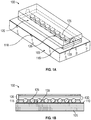
- Figure 1A is a diagram illustrating a lead connector 100 in accordance with one embodiment of the technology described herein. Additionally, Figure 1B is a diagram illustrating a cross-sectional view of the example lead connector 100 illustrated in Figure 1A .
- the example lead connector may include at least a base member 105, a flexible circuit 110, bottom casing 115, cover member 120, and lead connector contacts 125.
- the base member 105 may be made of an elastomeric material by way of example only. Additionally, the base member 105 may be made of any material with sufficient elastic properties to allow the base member 105 to be bent, stretched, twisted, or deformed, and when released, return to its original shape and dimensions.
- the elastic properties of the base material may be selected to allow the base to conform to the surface to which it is applied, flex sufficiently to allow a lead to be inserted into opening 130 located on either or both sides of cover member 120, and spring back with sufficient force to allow the lead connector contacts 125 to make sufficient electrical contact with the lead contacts.
- base member 105 may be made of any material as would be appreciated by one of ordinary skill in the art.
- a flexible circuit 110 may be mounted on the top surface of the base member 105.
- the flexible circuit 110 may include one or more layers of printed circuit connections and contacts, including traces that may be connected to or in contact with the lead connector contacts 125.
- the flexible circuit 110 and the underlying base member 105 may support the mechanical and electrical connections needed to ensure that the proper electrical connections are made so that electronic or medical devices may be supported when connected to the lead connector 100.
- the flexible circuit 110 may be designed to flex and bend as the base member 105 flexes and bends, so that both the flexible circuit 110 and the base member 105 may experience the same or near identical movement or conformed shape.
- lead connector contacts 125 are in the form of ball contacts, which may be made of or coated with a conductive material such as, for example, gold, silver, copper, graphite, platinum, tin, carbon, conductive polymers, or other conductive materials.
- lead connector contacts 125 are in the form of solder bumps or balls or other like structures affixed to the flexible circuit 110.
- Embodiments using ball contacts can be configured to allow the ball contacts to roll during insertion/extraction of the lead, providing easier acceptance and removal of the lead.
- a bottom casing 115 may be securely implanted or positioned on top of the flexible circuit 110.
- the bottom casing 115 may be a structure dimensioned to hold the ball contacts in place on their corresponding contacts on flexible circuit 110.
- the bottom casing 115 may include individual receptacles 135 dimensioned to contain an individual electrode ball contact 125 in place and large enough to allow the ball contacts to roll within the receptacles 135.
- the bottom casing 115 may have cut-outs at the bottom of each receptacle 135 so as to expose the surface of ball contacts 125 with the top surface of their corresponding contact on flexible circuit 110.
- the height of the receptacles 135 can be chosen such that the top surfaces of the ball contacts extend beyond the receptacle walls.
- An example of this is illustrated in Figure 1B , which shows ball contacts 125 as being taller than the walls of receptacles 135.
- receptacles 135 can be dimensioned with a smaller opening at the top (i.e., smaller than the diameter of the receptacle at the middle of the ball contacts) so that the receptacles 135 can hold the ball contacts in place on the contacts of flexible circuit 110.
- the bottom casing 115 may be configured so that a cover member 120 is securely fitted on top of the bottom casing 115. Furthermore, the cover member 120 may also detach from the bottom casing 115, which may allow a user or a medical professional to remove or replace the ball contacts 125 as needed.
- the cover member 120 is dimensioned such that when there is no lead inserted in lead connector 100, there is unobstructed space directly above the ball contacts 125, as more clearly depicted in Figure 1B . In such embodiments, when there is no lead inserted in lead connector 100 the ball contacts 125 may or may not be touching the flexible circuit 110.
- the cover member 120 may include an opening 130 on either or both ends of the cover member 120.
- the opening 130 may be configured to receive and guide a lead (not shown here) through the cover member 120 of the lead connector 100. Opening 130 may extend the entire length of cover member 120, or it may extend only part way through cover member 120. In some embodiments, the length of opening 130 is dimensioned such that it also forms a lead placement stop for the lead being inserted into the opening.
- the lead placement stop e.g., the end of the opening
- the lead contacts are lined up with the lead connector contacts.
- the lead itself can include a lead stop (such as, for example, a ring around the outer circumference of the lead) that can limit the amount by which the lead can be inserted into the lead connector housing. That is, the lead stop can be configured to contact the outer surface of cover member 120 when the lead is fully inserted.
- a lead stop such as, for example, a ring around the outer circumference of the lead
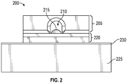
- FIG 2 is a diagram illustrating a side view of an example lead connector 200 in accordance with one embodiment of the technology described herein.
- This diagram illustrates an electrode ball contact 215 placed within a lead connector 200 as viewed through the opening.
- the electrode ball contact 215 may be free to float within the bottom casing 220 and cover member 205 areas when a lead (not shown here) is not placed through the opening 210.
- the ball contacts 215 may float vertically, in some embodiments they are restrained from horizontal movement by the walls of the receptacles in bottom casing 220 (e.g., the receptacles 135 of Figure 1 ).
- the electrode ball contact 215 may not make complete contact or be electrically engaged with the flexible circuit 230 located directly beneath the bottom casing 220.
- the height of the opening between the top of the receptacle walls and the ceiling, or inner surface, of cover member 205 is large enough to admit a lead but small enough so that the ball contacts do not escape from their respective receptacles.
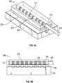
- Figure 3A is a diagram illustrating a lead connector 300 in an engaged state where a lead 305 is inserted in accordance with one embodiment of the technology described herein.
- Figure 3B illustrates a side view of the lead connector 300 illustrated in Figure 3A .
- An engaged state for purposes of this application may be used to indicate that a lead 305 is inserted into the lead connector 300 through the opening 320 located on both sides of the cover member 310.
- the lead 305 may include an array of electrical contacts 315 disposed along the length of an end portion of the lead 305.
- Each contact may be individually electrically connected to a separate internal conductor to provide, in this case, eight communication paths. Having the contacts wrap entirely around the lead allows freedom of orientation (e.g., rotational freedom) when placing the lead into the lead connector.
- other contact configurations can be provided on the lead such as, for example, a patch contact or a band that extends only partially around the lead circumference.
- eight lead contacts 315 are illustrated, other quantities of lead contacts 315 can be provided on the lead depending on the application or the need.
- the electrical contacts 315 may be positioned to pass a signal between their corresponding conductors in the lead, through ball contacts 325 to the circuit board when the lead electrical contacts 315 are touching the electrical ball contacts 325.
- the lead 305 may be inserted within the opening 320 so that the lead electrical contacts 315 located are aligned to make contact with the ball contacts 325.
- the lead 305 may push the ball contacts 325 downward, causing them to make contact with the flexible circuit 330. This is more clearly depicted in Figure 3B .
- the lead when the lead 305 is guided and pushed through the opening 320, the lead pushes ball contacts 325 downward to engage with the flexible circuit 330.
- the diameter of the lead (and lead contacts) may be chosen to provide a desired amount of deflection of the ball contacts 325.
- the amount of deflection of the ball contacts 325 may be sufficient to flex flexible circuit 330 and compress base member 335 as shown in the illustrated example. Because the flexible circuit 330 and the base member 335 may both be made of a flexible material, and because they may have elastic properties, the flexible circuit 330 and the base member 335 may both conform to the contours of the ball contacts 325 when the lead 305 is placed through the opening 320.
- Resistance provided by the elastic material can provide for a better electrical contact. Also, conformance of the flexible circuit to part of the surface of ball contacts 325 (i.e., the contact on the flexible circuit 300 wrapping part way around ball contact 325) can provide a greater surface area for the electrical contact than configurations in which the flexible circuit 300 does not conform to the circumference of the ball contact 325. Additionally, by having the lead 305 push down on the ball contacts, this may further ensure that the ball contacts are properly engaged with the flexible circuit 330.
- Figure 4 is a diagram illustrating an end view of the example lead connector where an electrode ball contact 405 is in contact with a lead 410 in accordance with one embodiment of the technology described.
- Figure 2 shows a lead connector 200 without a lead
- Figure 4 shows a lead 410 inserted within the lead connector 400 via an opening 430 on the cover member 420.
- the diameter of the lead 410 pushes the electrode ball contact 405 downward and forces the electrode ball contact 405 to engage with the flexible circuit 435 located on top of the base member 440.
- FIG. 5 is a diagram illustrating another example of a lead connector 500 in an engaged state where a lead 505 is inserted in accordance with one embodiment of the technology described herein.
- the two rows of ball contacts 510 may be connected in parallel to one another so that when a lead 505 is inserted through the opening 515, a single electrical contact 520 may be simultaneously in contact with a pair of ball contacts 510 located on opposite sides of one another.
- 2 or more ball contacts can be electrically connected to one another (e.g., via interconnects on the flexible circuit).
- Such embodiments provide multiple points of contact for a single electrical contact 520 of the lead 505, which may, for example, increase the current handling capacity of the connection. This is further illustrated in Figure 6 .
- each ball contact 510 in a pair may be electrically isolated from one another so that separate signal paths may be provided.
- separate, electrically isolated lead contacts may also be provided around the lead to facilitate the channel separation.
- FIG. 6 is a diagram illustrating a lead connector 600 with a lead 610 in contact with multiple ball contacts 605 in accordance with one embodiment of the technology described.
- the lead 610 when the lead 610 is inserted through the opening 615 located on the cover member 620, the lead pushes down on the ball contacts 605. Again, with the lead 610 engaged, this may force the ball contacts 605 to make contact with the flexible circuit 630 located on top of the base member 635, and thus securing an engaged electrical connection from the electrical contacts on the lead 610 to the flexible circuit 630.
- sufficient downforce may be provided to flex flexible circuit 630 and compress base member 635.
- the base member e.g. base member 635
- the flexible circuit can be mounted on a metal or plastic or other plate that flexes sufficiently to allow the ball contacts to deflect for lead insertion, yet is sufficiently resistant to such flexion so that sufficient electrical contact is made between the ball contacts and the electrical contacts on the lead.
- a backing plate can be mounted under the circuit board (or provided as a base of the circuit board) with one edge attached to a housing, such that the backing plate provides a cantilevered spring-like mechanism under the circuit board. Materials can be chosen such that the backing plate deflects sufficiently to allow the lead to be inserted into the connector, while providing sufficient pressure on the ball contacts so that they make good electrical contact with the lead contacts.
- FIG. 7 is a diagram illustrating a lead connector 700 with springs beneath the metal ball contacts 710 in accordance with one embodiment of the technology described.
- the springs 720 may be compression springs that are each located underneath the multiple lead connector contacts 710.
- the springs 720 implemented may be of various shapes and sizes, such as conical, cylindrical, hourglass, and barrel-shaped springs.
- the springs 720 may facilitate the electrical contact of the lead connector contacts 710 with the flexible circuit 715, and when the lead 705 is inserted through the lead connector 700, the lead 705 may push the lead connector contacts 710 into the flexible circuit and simultaneously cause the springs 720 underneath to compress while providing sufficient force in opposition to allow the lead connector contacts 710 to make sufficient electrical contact with the lead contacts 725.
- the illustrated example shows one spring aligned with each contact, as another example, the circuit board may be a rigid board and one or more springs mounted to apply pressure against the circuit board.
- module does not imply that the components or functionality described or claimed as part of the module are all configured in a common package. Indeed, any or all of the various components of a module, whether control logic or other components, can be combined in a single package or separately maintained and can further be distributed in multiple groupings or packages or across multiple locations.
Landscapes
- Health & Medical Sciences (AREA)
- Engineering & Computer Science (AREA)
- Biomedical Technology (AREA)
- Nuclear Medicine, Radiotherapy & Molecular Imaging (AREA)
- Radiology & Medical Imaging (AREA)
- Life Sciences & Earth Sciences (AREA)
- Animal Behavior & Ethology (AREA)
- General Health & Medical Sciences (AREA)
- Public Health (AREA)
- Veterinary Medicine (AREA)
- Coupling Device And Connection With Printed Circuit (AREA)
Applications Claiming Priority (1)
| Application Number | Priority Date | Filing Date | Title |
|---|---|---|---|
| US15/640,419 US9972951B1 (en) | 2017-06-30 | 2017-06-30 | Medical lead connectors with contact electrodes |
Publications (2)
| Publication Number | Publication Date |
|---|---|
| EP3421084A1 true EP3421084A1 (de) | 2019-01-02 |
| EP3421084B1 EP3421084B1 (de) | 2019-07-24 |
Family
ID=62091340
Family Applications (1)
| Application Number | Title | Priority Date | Filing Date |
|---|---|---|---|
| EP18180869.2A Active EP3421084B1 (de) | 2017-06-30 | 2018-06-29 | Medizinische leitungsverbinder mit kontaktelektroden |
Country Status (2)
| Country | Link |
|---|---|
| US (1) | US9972951B1 (de) |
| EP (1) | EP3421084B1 (de) |
Families Citing this family (4)
| Publication number | Priority date | Publication date | Assignee | Title |
|---|---|---|---|---|
| US10608390B2 (en) * | 2017-06-30 | 2020-03-31 | Benchmark Electronics, Inc. | Medical lead connectors with contact electrodes |
| US10644468B2 (en) * | 2017-06-30 | 2020-05-05 | Benchmark Electronics, Inc. | Medical lead connectors with contact electrodes |
| EP3940893A1 (de) * | 2018-05-15 | 2022-01-19 | Benchmark Electronics, Inc. | Medizinische leitungsverbinder mit kontaktelektroden |
| EP3648263B8 (de) * | 2018-11-02 | 2022-04-27 | Benchmark Electronics, Inc. | Medizinische leitungsverbinder mit kontaktelektroden |
Citations (4)
| Publication number | Priority date | Publication date | Assignee | Title |
|---|---|---|---|---|
| WO2003061469A1 (en) * | 2002-01-17 | 2003-07-31 | Ad-Tech Medical Instrument Corporation | Improved electrical connector for multi-contact medical electrodes |
| WO2007109762A1 (en) * | 2006-03-23 | 2007-09-27 | Medtronic, Inc. | Medical electrical lead connection systems and methods |
| US20080274651A1 (en) * | 2007-05-03 | 2008-11-06 | Boyd Garth W | Electrical connection apparatus |
| US8162684B1 (en) * | 2008-08-07 | 2012-04-24 | Jerzy Roman Sochor | Implantable connector with contact-containing feedthrough pins |
Family Cites Families (4)
| Publication number | Priority date | Publication date | Assignee | Title |
|---|---|---|---|---|
| US2767383A (en) * | 1954-01-04 | 1956-10-16 | Wate Electric Products Co | Circuit continuing device |
| US5070605A (en) * | 1988-04-22 | 1991-12-10 | Medtronic, Inc. | Method for making an in-line pacemaker connector system |
| US6662035B2 (en) * | 2001-09-13 | 2003-12-09 | Neuropace, Inc. | Implantable lead connector assembly for implantable devices and methods of using it |
| US8593816B2 (en) * | 2011-09-21 | 2013-11-26 | Medtronic, Inc. | Compact connector assembly for implantable medical device |
-
2017
- 2017-06-30 US US15/640,419 patent/US9972951B1/en active Active
-
2018
- 2018-06-29 EP EP18180869.2A patent/EP3421084B1/de active Active
Patent Citations (4)
| Publication number | Priority date | Publication date | Assignee | Title |
|---|---|---|---|---|
| WO2003061469A1 (en) * | 2002-01-17 | 2003-07-31 | Ad-Tech Medical Instrument Corporation | Improved electrical connector for multi-contact medical electrodes |
| WO2007109762A1 (en) * | 2006-03-23 | 2007-09-27 | Medtronic, Inc. | Medical electrical lead connection systems and methods |
| US20080274651A1 (en) * | 2007-05-03 | 2008-11-06 | Boyd Garth W | Electrical connection apparatus |
| US8162684B1 (en) * | 2008-08-07 | 2012-04-24 | Jerzy Roman Sochor | Implantable connector with contact-containing feedthrough pins |
Also Published As
| Publication number | Publication date |
|---|---|
| EP3421084B1 (de) | 2019-07-24 |
| US9972951B1 (en) | 2018-05-15 |
Similar Documents
| Publication | Publication Date | Title |
|---|---|---|
| EP3421084B1 (de) | Medizinische leitungsverbinder mit kontaktelektroden | |
| US10644468B2 (en) | Medical lead connectors with contact electrodes | |
| US8342887B2 (en) | Image guide wire connection | |
| US8118604B2 (en) | Socket connector having electrical element supported by insulated elastomer | |
| EP0681749B1 (de) | Verbinder fuer eine flexible schaltung | |
| CA2167065A1 (en) | Edge-connecting printed circuit board | |
| US7572131B2 (en) | Electrical interconnect system utilizing non-conductive elastomeric elements | |
| CA2300350A1 (en) | An electrical connecting device | |
| US7806699B2 (en) | Wound coil compression connector | |
| EP3570390B1 (de) | Medizinische leitungsverbinder mit kontaktelektroden | |
| EP1898497B1 (de) | Verbinder und Kontakte zur Verwendung mit dem Verbinder | |
| US20120315772A1 (en) | Solderless connector for microelectronics | |
| US7833019B2 (en) | Spring beam wafer connector | |
| US12456830B2 (en) | Connector | |
| US10103471B1 (en) | Reversible connector interface | |
| US10608390B2 (en) | Medical lead connectors with contact electrodes | |
| EP3648263B1 (de) | Medizinische leitungsverbinder mit kontaktelektroden | |
| US9147956B2 (en) | Helical spring, connector, electrode and electrometer | |
| US9024619B2 (en) | Connection system for sensor device | |
| KR20180106203A (ko) | 가이드몰드의 내측에 경사 탄성전도판을 구비한 센서용 신호전달 조립체 | |
| JP2008097929A (ja) | 極細同軸線ハーネス、極細同軸線ハーネス接続体、および極細同軸線ハーネスの接続方法 | |
| JPH02503967A (ja) | 電気ソケット |
Legal Events
| Date | Code | Title | Description |
|---|---|---|---|
| PUAI | Public reference made under article 153(3) epc to a published international application that has entered the european phase |
Free format text: ORIGINAL CODE: 0009012 |
|
| STAA | Information on the status of an ep patent application or granted ep patent |
Free format text: STATUS: THE APPLICATION HAS BEEN PUBLISHED |
|
| AK | Designated contracting states |
Kind code of ref document: A1 Designated state(s): AL AT BE BG CH CY CZ DE DK EE ES FI FR GB GR HR HU IE IS IT LI LT LU LV MC MK MT NL NO PL PT RO RS SE SI SK SM TR |
|
| AX | Request for extension of the european patent |
Extension state: BA ME |
|
| STAA | Information on the status of an ep patent application or granted ep patent |
Free format text: STATUS: REQUEST FOR EXAMINATION WAS MADE |
|
| GRAP | Despatch of communication of intention to grant a patent |
Free format text: ORIGINAL CODE: EPIDOSNIGR1 |
|
| STAA | Information on the status of an ep patent application or granted ep patent |
Free format text: STATUS: GRANT OF PATENT IS INTENDED |
|
| 17P | Request for examination filed |
Effective date: 20190117 |
|
| RBV | Designated contracting states (corrected) |
Designated state(s): AL AT BE BG CH CY CZ DE DK EE ES FI FR GB GR HR HU IE IS IT LI LT LU LV MC MK MT NL NO PL PT RO RS SE SI SK SM TR |
|
| RIC1 | Information provided on ipc code assigned before grant |
Ipc: A61N 1/375 20060101AFI20190208BHEP |
|
| INTG | Intention to grant announced |
Effective date: 20190227 |
|
| RIN1 | Information on inventor provided before grant (corrected) |
Inventor name: JOHNS, DANIEL WILLIAM Inventor name: HIGGINS, DANIEL PATRICK Inventor name: WHITE, ROBERT RAYMOND |
|
| GRAS | Grant fee paid |
Free format text: ORIGINAL CODE: EPIDOSNIGR3 |
|
| GRAA | (expected) grant |
Free format text: ORIGINAL CODE: 0009210 |
|
| STAA | Information on the status of an ep patent application or granted ep patent |
Free format text: STATUS: THE PATENT HAS BEEN GRANTED |
|
| AK | Designated contracting states |
Kind code of ref document: B1 Designated state(s): AL AT BE BG CH CY CZ DE DK EE ES FI FR GB GR HR HU IE IS IT LI LT LU LV MC MK MT NL NO PL PT RO RS SE SI SK SM TR |
|
| REG | Reference to a national code |
Ref country code: GB Ref legal event code: FG4D |
|
| REG | Reference to a national code |
Ref country code: CH Ref legal event code: EP |
|
| REG | Reference to a national code |
Ref country code: DE Ref legal event code: R096 Ref document number: 602018000300 Country of ref document: DE |
|
| REG | Reference to a national code |
Ref country code: AT Ref legal event code: REF Ref document number: 1157494 Country of ref document: AT Kind code of ref document: T Effective date: 20190815 |
|
| REG | Reference to a national code |
Ref country code: IE Ref legal event code: FG4D |
|
| REG | Reference to a national code |
Ref country code: NL Ref legal event code: MP Effective date: 20190724 |
|
| REG | Reference to a national code |
Ref country code: LT Ref legal event code: MG4D |
|
| REG | Reference to a national code |
Ref country code: AT Ref legal event code: MK05 Ref document number: 1157494 Country of ref document: AT Kind code of ref document: T Effective date: 20190724 |
|
| PG25 | Lapsed in a contracting state [announced via postgrant information from national office to epo] |
Ref country code: PT Free format text: LAPSE BECAUSE OF FAILURE TO SUBMIT A TRANSLATION OF THE DESCRIPTION OR TO PAY THE FEE WITHIN THE PRESCRIBED TIME-LIMIT Effective date: 20191125 Ref country code: NL Free format text: LAPSE BECAUSE OF FAILURE TO SUBMIT A TRANSLATION OF THE DESCRIPTION OR TO PAY THE FEE WITHIN THE PRESCRIBED TIME-LIMIT Effective date: 20190724 Ref country code: HR Free format text: LAPSE BECAUSE OF FAILURE TO SUBMIT A TRANSLATION OF THE DESCRIPTION OR TO PAY THE FEE WITHIN THE PRESCRIBED TIME-LIMIT Effective date: 20190724 Ref country code: AT Free format text: LAPSE BECAUSE OF FAILURE TO SUBMIT A TRANSLATION OF THE DESCRIPTION OR TO PAY THE FEE WITHIN THE PRESCRIBED TIME-LIMIT Effective date: 20190724 Ref country code: LT Free format text: LAPSE BECAUSE OF FAILURE TO SUBMIT A TRANSLATION OF THE DESCRIPTION OR TO PAY THE FEE WITHIN THE PRESCRIBED TIME-LIMIT Effective date: 20190724 Ref country code: BG Free format text: LAPSE BECAUSE OF FAILURE TO SUBMIT A TRANSLATION OF THE DESCRIPTION OR TO PAY THE FEE WITHIN THE PRESCRIBED TIME-LIMIT Effective date: 20191024 Ref country code: SE Free format text: LAPSE BECAUSE OF FAILURE TO SUBMIT A TRANSLATION OF THE DESCRIPTION OR TO PAY THE FEE WITHIN THE PRESCRIBED TIME-LIMIT Effective date: 20190724 Ref country code: FI Free format text: LAPSE BECAUSE OF FAILURE TO SUBMIT A TRANSLATION OF THE DESCRIPTION OR TO PAY THE FEE WITHIN THE PRESCRIBED TIME-LIMIT Effective date: 20190724 Ref country code: NO Free format text: LAPSE BECAUSE OF FAILURE TO SUBMIT A TRANSLATION OF THE DESCRIPTION OR TO PAY THE FEE WITHIN THE PRESCRIBED TIME-LIMIT Effective date: 20191024 |
|
| PG25 | Lapsed in a contracting state [announced via postgrant information from national office to epo] |
Ref country code: RS Free format text: LAPSE BECAUSE OF FAILURE TO SUBMIT A TRANSLATION OF THE DESCRIPTION OR TO PAY THE FEE WITHIN THE PRESCRIBED TIME-LIMIT Effective date: 20190724 Ref country code: LV Free format text: LAPSE BECAUSE OF FAILURE TO SUBMIT A TRANSLATION OF THE DESCRIPTION OR TO PAY THE FEE WITHIN THE PRESCRIBED TIME-LIMIT Effective date: 20190724 Ref country code: IS Free format text: LAPSE BECAUSE OF FAILURE TO SUBMIT A TRANSLATION OF THE DESCRIPTION OR TO PAY THE FEE WITHIN THE PRESCRIBED TIME-LIMIT Effective date: 20191124 Ref country code: AL Free format text: LAPSE BECAUSE OF FAILURE TO SUBMIT A TRANSLATION OF THE DESCRIPTION OR TO PAY THE FEE WITHIN THE PRESCRIBED TIME-LIMIT Effective date: 20190724 Ref country code: ES Free format text: LAPSE BECAUSE OF FAILURE TO SUBMIT A TRANSLATION OF THE DESCRIPTION OR TO PAY THE FEE WITHIN THE PRESCRIBED TIME-LIMIT Effective date: 20190724 Ref country code: GR Free format text: LAPSE BECAUSE OF FAILURE TO SUBMIT A TRANSLATION OF THE DESCRIPTION OR TO PAY THE FEE WITHIN THE PRESCRIBED TIME-LIMIT Effective date: 20191025 |
|
| PG25 | Lapsed in a contracting state [announced via postgrant information from national office to epo] |
Ref country code: TR Free format text: LAPSE BECAUSE OF FAILURE TO SUBMIT A TRANSLATION OF THE DESCRIPTION OR TO PAY THE FEE WITHIN THE PRESCRIBED TIME-LIMIT Effective date: 20190724 |
|
| PG25 | Lapsed in a contracting state [announced via postgrant information from national office to epo] |
Ref country code: DK Free format text: LAPSE BECAUSE OF FAILURE TO SUBMIT A TRANSLATION OF THE DESCRIPTION OR TO PAY THE FEE WITHIN THE PRESCRIBED TIME-LIMIT Effective date: 20190724 Ref country code: EE Free format text: LAPSE BECAUSE OF FAILURE TO SUBMIT A TRANSLATION OF THE DESCRIPTION OR TO PAY THE FEE WITHIN THE PRESCRIBED TIME-LIMIT Effective date: 20190724 Ref country code: RO Free format text: LAPSE BECAUSE OF FAILURE TO SUBMIT A TRANSLATION OF THE DESCRIPTION OR TO PAY THE FEE WITHIN THE PRESCRIBED TIME-LIMIT Effective date: 20190724 Ref country code: IT Free format text: LAPSE BECAUSE OF FAILURE TO SUBMIT A TRANSLATION OF THE DESCRIPTION OR TO PAY THE FEE WITHIN THE PRESCRIBED TIME-LIMIT Effective date: 20190724 Ref country code: PL Free format text: LAPSE BECAUSE OF FAILURE TO SUBMIT A TRANSLATION OF THE DESCRIPTION OR TO PAY THE FEE WITHIN THE PRESCRIBED TIME-LIMIT Effective date: 20190724 |
|
| PG25 | Lapsed in a contracting state [announced via postgrant information from national office to epo] |
Ref country code: IS Free format text: LAPSE BECAUSE OF FAILURE TO SUBMIT A TRANSLATION OF THE DESCRIPTION OR TO PAY THE FEE WITHIN THE PRESCRIBED TIME-LIMIT Effective date: 20200224 Ref country code: SM Free format text: LAPSE BECAUSE OF FAILURE TO SUBMIT A TRANSLATION OF THE DESCRIPTION OR TO PAY THE FEE WITHIN THE PRESCRIBED TIME-LIMIT Effective date: 20190724 Ref country code: SK Free format text: LAPSE BECAUSE OF FAILURE TO SUBMIT A TRANSLATION OF THE DESCRIPTION OR TO PAY THE FEE WITHIN THE PRESCRIBED TIME-LIMIT Effective date: 20190724 Ref country code: CZ Free format text: LAPSE BECAUSE OF FAILURE TO SUBMIT A TRANSLATION OF THE DESCRIPTION OR TO PAY THE FEE WITHIN THE PRESCRIBED TIME-LIMIT Effective date: 20190724 |
|
| REG | Reference to a national code |
Ref country code: DE Ref legal event code: R097 Ref document number: 602018000300 Country of ref document: DE |
|
| PLBE | No opposition filed within time limit |
Free format text: ORIGINAL CODE: 0009261 |
|
| STAA | Information on the status of an ep patent application or granted ep patent |
Free format text: STATUS: NO OPPOSITION FILED WITHIN TIME LIMIT |
|
| PG2D | Information on lapse in contracting state deleted |
Ref country code: IS |
|
| 26N | No opposition filed |
Effective date: 20200603 |
|
| PG25 | Lapsed in a contracting state [announced via postgrant information from national office to epo] |
Ref country code: MC Free format text: LAPSE BECAUSE OF FAILURE TO SUBMIT A TRANSLATION OF THE DESCRIPTION OR TO PAY THE FEE WITHIN THE PRESCRIBED TIME-LIMIT Effective date: 20190724 |
|
| PG25 | Lapsed in a contracting state [announced via postgrant information from national office to epo] |
Ref country code: LU Free format text: LAPSE BECAUSE OF NON-PAYMENT OF DUE FEES Effective date: 20200629 |
|
| REG | Reference to a national code |
Ref country code: BE Ref legal event code: MM Effective date: 20200630 |
|
| PG25 | Lapsed in a contracting state [announced via postgrant information from national office to epo] |
Ref country code: IE Free format text: LAPSE BECAUSE OF NON-PAYMENT OF DUE FEES Effective date: 20200629 |
|
| PG25 | Lapsed in a contracting state [announced via postgrant information from national office to epo] |
Ref country code: BE Free format text: LAPSE BECAUSE OF NON-PAYMENT OF DUE FEES Effective date: 20200630 |
|
| REG | Reference to a national code |
Ref country code: CH Ref legal event code: PL |
|
| PG25 | Lapsed in a contracting state [announced via postgrant information from national office to epo] |
Ref country code: LI Free format text: LAPSE BECAUSE OF NON-PAYMENT OF DUE FEES Effective date: 20210630 Ref country code: CH Free format text: LAPSE BECAUSE OF NON-PAYMENT OF DUE FEES Effective date: 20210630 |
|
| PG25 | Lapsed in a contracting state [announced via postgrant information from national office to epo] |
Ref country code: MT Free format text: LAPSE BECAUSE OF FAILURE TO SUBMIT A TRANSLATION OF THE DESCRIPTION OR TO PAY THE FEE WITHIN THE PRESCRIBED TIME-LIMIT Effective date: 20190724 Ref country code: CY Free format text: LAPSE BECAUSE OF FAILURE TO SUBMIT A TRANSLATION OF THE DESCRIPTION OR TO PAY THE FEE WITHIN THE PRESCRIBED TIME-LIMIT Effective date: 20190724 |
|
| PG25 | Lapsed in a contracting state [announced via postgrant information from national office to epo] |
Ref country code: MK Free format text: LAPSE BECAUSE OF FAILURE TO SUBMIT A TRANSLATION OF THE DESCRIPTION OR TO PAY THE FEE WITHIN THE PRESCRIBED TIME-LIMIT Effective date: 20190724 |
|
| PGFP | Annual fee paid to national office [announced via postgrant information from national office to epo] |
Ref country code: GB Payment date: 20220707 Year of fee payment: 5 Ref country code: DE Payment date: 20220705 Year of fee payment: 5 |
|
| PGFP | Annual fee paid to national office [announced via postgrant information from national office to epo] |
Ref country code: FR Payment date: 20220727 Year of fee payment: 5 |
|
| P01 | Opt-out of the competence of the unified patent court (upc) registered |
Effective date: 20230520 |
|
| PG25 | Lapsed in a contracting state [announced via postgrant information from national office to epo] |
Ref country code: SI Free format text: LAPSE BECAUSE OF FAILURE TO SUBMIT A TRANSLATION OF THE DESCRIPTION OR TO PAY THE FEE WITHIN THE PRESCRIBED TIME-LIMIT Effective date: 20190724 |
|
| REG | Reference to a national code |
Ref country code: DE Ref legal event code: R119 Ref document number: 602018000300 Country of ref document: DE |
|
| GBPC | Gb: european patent ceased through non-payment of renewal fee |
Effective date: 20230629 |
|
| PG25 | Lapsed in a contracting state [announced via postgrant information from national office to epo] |
Ref country code: DE Free format text: LAPSE BECAUSE OF NON-PAYMENT OF DUE FEES Effective date: 20240103 Ref country code: GB Free format text: LAPSE BECAUSE OF NON-PAYMENT OF DUE FEES Effective date: 20230629 |
|
| PG25 | Lapsed in a contracting state [announced via postgrant information from national office to epo] |
Ref country code: FR Free format text: LAPSE BECAUSE OF NON-PAYMENT OF DUE FEES Effective date: 20230630 |