EP3420887A1 - Method for determining the position of the eye rotation center of the eye of a subject, and associated device - Google Patents
Method for determining the position of the eye rotation center of the eye of a subject, and associated device Download PDFInfo
- Publication number
- EP3420887A1 EP3420887A1 EP17179209.6A EP17179209A EP3420887A1 EP 3420887 A1 EP3420887 A1 EP 3420887A1 EP 17179209 A EP17179209 A EP 17179209A EP 3420887 A1 EP3420887 A1 EP 3420887A1
- Authority
- EP
- European Patent Office
- Prior art keywords
- eye
- subject
- rotation center
- erc
- image
- Prior art date
- Legal status (The legal status is an assumption and is not a legal conclusion. Google has not performed a legal analysis and makes no representation as to the accuracy of the status listed.)
- Granted
Links
Images


Classifications
-
- A—HUMAN NECESSITIES
- A61—MEDICAL OR VETERINARY SCIENCE; HYGIENE
- A61B—DIAGNOSIS; SURGERY; IDENTIFICATION
- A61B3/00—Apparatus for testing the eyes; Instruments for examining the eyes
- A61B3/0016—Operational features thereof
- A61B3/0025—Operational features thereof characterised by electronic signal processing, e.g. eye models
-
- G—PHYSICS
- G02—OPTICS
- G02C—SPECTACLES; SUNGLASSES OR GOGGLES INSOFAR AS THEY HAVE THE SAME FEATURES AS SPECTACLES; CONTACT LENSES
- G02C7/00—Optical parts
- G02C7/02—Lenses; Lens systems ; Methods of designing lenses
- G02C7/024—Methods of designing ophthalmic lenses
- G02C7/027—Methods of designing ophthalmic lenses considering wearer's parameters
-
- G—PHYSICS
- G02—OPTICS
- G02C—SPECTACLES; SUNGLASSES OR GOGGLES INSOFAR AS THEY HAVE THE SAME FEATURES AS SPECTACLES; CONTACT LENSES
- G02C7/00—Optical parts
- G02C7/02—Lenses; Lens systems ; Methods of designing lenses
- G02C7/024—Methods of designing ophthalmic lenses
- G02C7/028—Special mathematical design techniques
-
- G—PHYSICS
- G02—OPTICS
- G02C—SPECTACLES; SUNGLASSES OR GOGGLES INSOFAR AS THEY HAVE THE SAME FEATURES AS SPECTACLES; CONTACT LENSES
- G02C13/00—Assembling; Repairing; Cleaning
- G02C13/003—Measuring during assembly or fitting of spectacles
- G02C13/005—Measuring geometric parameters required to locate ophtalmic lenses in spectacles frames
Definitions
- the invention relates to the fields of optometry and optical metrology.
- the invention relates to a device and a method for determining the position of the eye rotation center of the eye of a subject.
- the invention relates also to a method for calculating an ophthalmic lens using this method.
- the position of a center of rotation of at least one of the eyes is determined.
- Movements of each eye of a subject can generally be considered as being a combination of rotations about a particular point that is referred to as the center of rotation of the eye or "eye rotation center”, hereinafter also referred to as ERC.
- the position of the ERC may be deduced approximately from the position of the cornea by assuming a mean value for the radius of the eye, typically a value of about 15 millimeters (mm).
- a mean value for the radius of the eye typically a value of about 15 millimeters (mm).
- the radius of the eye varies significantly from one subject to another, such that this approximation leads to significant errors that are highly penalizing for the pertinence of the personalized optical design calculation.
- the reference accessory gives information on the relative position of the head of the subject and the image capture device.
- one object of the invention is to provide an easy-to-implement method to determine quickly an approximate value of the position of the ERC of a subject, in particular without the need of using a reference accessory.
- a method for determining a position of the eye rotation center of an eye of a subject comprising:
- geometric model of the eye, one understands any physical model adapted to summarize both the optical path of the light through a human eye, and also the movements of this eye.
- a simple geometric model may be used wherein the geometry of the eye is partially modeled with only two spheres nested one in the other (see Lefohn A. et al., "An ocularist's approach to human iris synthesis", IEEE Computer Graphics and Applications, Vol. 23, Issue 6, Nov.-Dec. 2003 ).
- a first part of one sphere can be contemplated as the sclera of the eye: the eye rotation center is positioned at the center of this sphere.
- a second part of the other sphere can be contemplated as the cornea of the eye.
- Another possible geometric model may be used wherein the geometry of the eye is modeled with one sphere for the sclera of the eye and one ellipsoid for the cornea of the eye.
- the position of the eye rotation may be determined as a function of:
- the eccentricity of the cornea may be found by a measurement using an apparatus called an auto kerato-refractometer (also known as "AKR" ) , for example the VX120 Multi-Diagnostic Unit from the US company Visionix.
- an auto kerato-refractometer also known as "AKR”
- VX120 Multi-Diagnostic Unit from the US company Visionix.
- the invention also relates to a method for calculating a personalized ophthalmic lens for a subject comprising:
- the invention finally relates to a device for determining a position of the eye rotation center of an eye of a subject.
- said device comprises:
- the device further comprises a calibration system.
- the calibration system comprises a calibration scale of predetermined dimension, the image-capture apparatus being further configured to acquire at least one facial image of the eye including at least a portion of said calibration scale.
- the calibration system comprises an image-capture apparatus that is configured to acquire two distinct facial images of said eye, the image-processing means being configured to determine the measured value of an outer diameter of an iris of said eye on the basis of two distinct facial images.
- the image-capture apparatus comprises a first image-capture apparatus and a second image-capture apparatus that are spaced from each other by a predetermined separation distance, each image-capture apparatus being configured to acquire at least one facial image of said eye.
- FIG. 1 a section view of a simplified physiological structure of a human eye 1 (one the two eyes of a subject, who is not represented on fig. 1 ).
- This structure is basically, with a quite good approximation, a shape of revolution around an optical axis 3, said optical axis 3 passing by the eye rotation center 2 (hereinafter noted ERC) of the eye 1.
- ERC eye rotation center 2
- the eye 1 comprises mainly a cornea 10, an intra-ocular lens 20 (hereinafter referred to as lens 20) of variable optical power, and a sclera 30.
- the cornea 10 is formed by two surfaces 11, 12: a front (anterior) face 11 and a rear (posterior) face 12. Geometrically, those surfaces are in reality very complex, e . g . aspherical, yet in practice, and in the framework of this application, one will assume that the front face 11 and the rear face 12 are substantially spherical surfaces having said optical axis 3 as an axis of revolution (the respective centers of the two spheres are on this optical axis), said optical axis 3 intersecting said surfaces 11, 12 at points 13, 19 (see fig. 1 ). In the following, the intersection point 13 will be referred to as the "apex" of the cornea 10.
- the front and back faces 11, 12 of the cornea 10 form two optical spherical (concave) diopters of radius R C,1 and R C,2 which have here positive values with the geometrical convention chosen for figure 1 (see arrow at the top of this figure indicating the direction of propagating light).
- anterior chamber 14 of the eye 1 which contains a liquid, the "aqueous humor” , which is an optically transparent medium with a refractive index n AH around 1.33.
- This anterior chamber 14 hence extends from the rear face 12 to the front face 21 of the lens 20, said front face 21 being pressed against the iris 18 of the eye 1 (although in figure 1 it is not the case for the sake of clarity), so that the front face 21 of the lens 20 is approximately coplanar with the pupil 15 of the eye 1.
- the “anterior chamber depth” (hereinafter also referred to as "ACD”) is the distance d AC from the rear apex 19 of the cornea 10 to the front apex 24 of the lens 20.
- This distance d AC is generally comprised between 3 and 4 mm, and decreases with the age of the subject (see below).
- the iris 18 of the eye 1 clings to the cornea 10 and the sclera 30 at two transitional regions 16, 17 also known as the "corneal limbi" of the eye 1.
- the lens 20 is formed by two surfaces 21, 22 of revolution around the optical axis 3: the front face 21 and the rear face 22 of the lens 20.
- Those lens surfaces 21, 22 are not only of very complex shape - typically aspherical - but also change of shape with accommodation of the eye 1 (increase of the optical power of the eye 1 by modifying the front and/or the shapes of the front and rear surfaces 21, 22).
- the eye 1 is here at rest, namely without accommodation and with lowest optical power.
- the base thickness t L of the lens 20 between the front apex 24 and the rear apex 25 of the lens 20 is comprised between 3 and 5 mm (the thickness t L of the lens 20 vary also as a function of accommodation).
- the front and back faces 21, 22 of the lens 20 form two optical spherical diopters of radius R L,1 (concave, positive) and R L,2 (concave, negative) separated by the base thickness t L of the lens 20.
- the rest of the eye 1 is formed by the sclera 30 which takes around 5/6 th of circumference of the eye 1, and by the vitreous body 32, which is basically a transparent aqueous liquid contained in the eye 1, filling the space comprised between the rear face 22 of the lens 20 and the retina 31 which partially covers the internal surface of the sclera 30.
- the optical axis 3 of the eye 1 intersects the retina 31 at the foveal zone 33, also known as the fovea, which is the area of the retina 31 with the highest visual acuity (highest concentration of sensitive photo-receptors) where the images of objects or persons seen by the subject are formed optically.
- the ERC 2 On the optical axis 3 is the ERC 2 which is aligned with the apex 13 of the cornea 10 and with the fovea 33 of the sclera 30.
- the distance L E from the apex 13 to the fovea 33 (see fig. 2 ) is referred to as the "length" of the eye 1 and is typically comprised between 20 and 30 mm, more often between 22 mm and 27 mm.
- the position of the ERC 2 may be determined for example by the raw data of the distance d ERC (see figure 1 ) between the apex 13 of the cornea 10 and the ERC 2.
- the position of the ERC 2 may be difficult to determine directly not only because the ERC 2 is internal to the eye 1 but also because its actual position depends on many other parameters, most of them, like the anterior chamber depth d AC , lens thickness t L , eye length L E being difficult to measure directly.
- direct measurement it is meant a simple geometrical measurement, e.g. with a simple graduated ruler.
- the set of personal parameters includes only geometric dimensions of the eye 1.
- FIG 2 a possible geometric model of the eye 1 of figure 1 .
- This geometric model is built on the assumption that the sclera 30 and the cornea 10 are respectively a part of a first and a second spheres.
- this geometric model is a model of the sclera 30 and of the cornea 10 of the eye 1, said sclera 30 being modeled (see figure 2 ) by a first sphere (see first circle C 1 drawn on fig. 2 ) having a first radius R 1 and said cornea 10 being modeled by a second sphere (see second circle C 2 drawn on fig. 2 ) having a second radius R 2 smaller than the first radius R 1 (R 2 ⁇ R 1 ), said first sphere and said second sphere having a first center P 1 and a second center P 2 respectively, said first center P 1 and said second center P 2 being aligned on a straight line A defining the optical axis 3 of the eye 1.
- the distance P 1 P 2 between the two centers P 1 and P 2 is such that P 1 P 2 ⁇ (R 1 2 - R 2 2 ) 1 ⁇ 2 .
- these two spheres are represented by two circles C 1 , C 2 , whose part drawn with a solid line (---) corresponds respectively to the cornea 10 and to the sclera 30.
- the parts of the circles C 1 , C 2 drawn with a dashed line (- -) on figure 2 have no physical reality and have been represented here only of the sake of understanding.
- the ERC 2 is positioned at the center P 1 of the first circle C 1 .
- the corneal limbi 16, 17 of the eye 1 in figure 1 correspond to the intersection points P 6 , P 7 of the first circle C 1 with the second circle C 2 .
- the segment [P 6 P 7 ] joining the intersection points P 6 , P 7 may be considered to be in the same plane as the pupil 15 and the iris 18 of the eye 1: it crosses perpendicularly the straight line A (i.e. the optical axis 3) at point P 5 .
- the outer diameter D I of the iris 18 may be easily measured geometrically. One thus may choose the outer diameter D I of the iris 18 as the first geometric dimension of the eye 1 of the subject to be included in the geometric model.
- the step of measuring a first value of the outer diameter D I of the iris 18 comprises:
- the invention also provides a device for determining the position d ERC of the eye rotation center 2 of the eye 1 of the subject, said device comprising:
- the present device is obviously not limited to a calibration scale, and we can imagine any other calibration system that would be configured so that the calculation means can determine an approximate value of the position of the eye rotation center on the basis of a facial image of the eye.
- the calculation means comprise a geometric model of the eye of the subject such as, for example, the one described above (2-spheres model).
- the image-processing means and calculation means may be a computer receiving the facial image from the image-capture apparatus.
- the device for determining a position of the eye rotation center of an eye of a subject comprises:
- the step of measuring a first value of the outer diameter D I of the iris 18 may comprise:
- the method according to the invention one assesses the remaining values of the remaining geometric dimensions of the geometric model, that is the eye length L E ; and the anterior chamber depth d AC (the distance between point P 3 and P 5 in figure 2 ).
- the anterior chamber depth can be measured using an apparatus called an auto kerato-refractometer (also known as "AKR" ) , for example the VX120 Multi-Diagnostic Unit from the US company Visionix.
- ARR auto kerato-refractometer
- a value of the eye length L E shall be now assessed in order to determine the position (here the distance d ERC , see fig. 2 ) of the ERC 2 of the eye 1 of the subject.
- optical power P E of said eye 1 may be either measured (using for example the same apparatus VX110) directly or evaluated directly using tabulated data, eventually depending on personal parameters of the subject.
- the eye length L E which is the geometric distance between the apex 13 of the cornea 10 and the fovea 33 of the sclera 30, can be calculated, in the paraxial approximation, as a function of geometric and optical parameters of the eye 1.
- figure 4 a schematic optical drawing, in the paraxial approximation, of the eye 1 of the subject, here with a corrective ophthalmic lens 6 corresponding to the need K of visual correction for the subject.
- S C ,1 F' SYS > 0
- H E (object) and H' E (image) of the eye 1 made up by association of cornea 10 and lens 20
- H C H E ⁇ n 0 ⁇ d CL n AH ⁇ P L
- H E H L ′ H ′ E ⁇ ⁇ n VH ⁇ d CL n AH ⁇ P C P E .
- Figure 5 shows an example of result for the calculation of the eye length L E as a function of the outer diameter D I of the iris 18 of the eye 1 of the subject. This result has been obtained using the data tabulated for the above-mentioned variables from Tan, Bo, "Optical Modeling of Schematic Eyes and the Ophthalmic Applications” - PhD dissertation, University of Tennessee, 2009 - http://trace.tennessee.edu/utk graddiss/63 .
- the eye length L E is comprised between around 20 mm and 28 mm.
- the curve 8 is a quasi straight line, showing that the eye length L E varies linearly with the need K in visual correction.
- Figure 6 shows a 3D plot of the position dERC of the ERC 2 of the eye 1 of the subject as a function of age and need K (in diopters) of visual correction.
- a first approximate value of the position d ERC of the ERC 2 After having determined a first approximate value of the position d ERC of the ERC 2 performing the different steps above, one then compares said first approximate value with a reference value d ERC,ref , e . g . found in a geometrical database which stores an huge amount of measured values of the position d ERC as function of age, need in visual correction, gender, and/or ethnicity, etc...; and one determines a second approximate value of said position of the eye rotation center based on the result of said comparison.
- the step of determining the second approximate value of the position of said eye comprises:
- determining the second approximate value of the position of said eye rotation center comprises:
Landscapes
- Physics & Mathematics (AREA)
- Health & Medical Sciences (AREA)
- Ophthalmology & Optometry (AREA)
- Life Sciences & Earth Sciences (AREA)
- General Health & Medical Sciences (AREA)
- General Physics & Mathematics (AREA)
- Optics & Photonics (AREA)
- Engineering & Computer Science (AREA)
- Biophysics (AREA)
- Surgery (AREA)
- Mathematical Physics (AREA)
- Biomedical Technology (AREA)
- Heart & Thoracic Surgery (AREA)
- Medical Informatics (AREA)
- Molecular Biology (AREA)
- Signal Processing (AREA)
- Animal Behavior & Ethology (AREA)
- Public Health (AREA)
- Veterinary Medicine (AREA)
- Geometry (AREA)
- Eye Examination Apparatus (AREA)
- Eyeglasses (AREA)
- Prostheses (AREA)
Abstract
- providing a geometric model of an eye, whereby the position of the eye rotation center of this eye is determined based on a set of personal parameters (LE, dAC, DI, AGE, K) including at least a first geometric dimension (DI) of the eye, each personal parameter being distinct from said position of the eye rotation center;
- determining a value of each personal parameter for the subject; and
- determining a first approximate value of said position of the eye rotation center in accordance with said geometric model based on the values of the personal parameters.
Description
- The invention relates to the fields of optometry and optical metrology.
- More precisely, the invention relates to a device and a method for determining the position of the eye rotation center of the eye of a subject.
- The invention relates also to a method for calculating an ophthalmic lens using this method.
- In order to customize the ophthalmic lens for a specific subject, geometrical, postural and behavioral parameters of the subject and/or of the subject with his/her eyeglasses need to be determined.
- Among these parameters, the position of a center of rotation of at least one of the eyes is determined.
- Movements of each eye of a subject can generally be considered as being a combination of rotations about a particular point that is referred to as the center of rotation of the eye or "eye rotation center", hereinafter also referred to as ERC.
- It is desirable to determine the position of this particular point, for example to perform calculations of a personalized optical design by ray tracing for the corrective lens that is to be fitted properly to a frame chosen by the subject.
- In present practice, the position of the ERC may be deduced approximately from the position of the cornea by assuming a mean value for the radius of the eye, typically a value of about 15 millimeters (mm). Unfortunately, the radius of the eye varies significantly from one subject to another, such that this approximation leads to significant errors that are highly penalizing for the pertinence of the personalized optical design calculation.
- In order to determine the position of the ERC, it is also known a method based on image processing, wherein one captures, by means of an image capture apparatus, at least two facial images of the subject equipped with a reference accessory while the subject looks at this image capture apparatus.
- These images are treated in order to determine the ERC. The reference accessory gives information on the relative position of the head of the subject and the image capture device.
- However, such method takes time to be carried out and is not particularly well suited to be performed rapidly in the shop of an eye-care practitioner.
- Moreover, such method is very precise, whereas a lower level of precision is required, for example to discriminate those patients having an ERC with a position situated outside of the normal range.
- Therefore one object of the invention is to provide an easy-to-implement method to determine quickly an approximate value of the position of the ERC of a subject, in particular without the need of using a reference accessory.
- The above object is achieved according to the invention by a method for determining a position of the eye rotation center of an eye of a subject comprising:
- providing a geometric model of an eye, whereby the position of the eye rotation center of this eye is determined based on a set of personal parameters including at least a first geometric dimension of the eye, each personal parameter being distinct from said position of the eye rotation center of the eye;
- determining a value of each personal parameter for the subject; and
- determining a first approximate value of said position of the eye rotation center of the subject in accordance with said geometric model based on the values of the personal parameters.
- By "geometric model" of the eye, one understands any physical model adapted to summarize both the optical path of the light through a human eye, and also the movements of this eye.
- As the physiological structure of a human eye is very complicated, a complete geometric model of an eye is very hard to elaborate, taking into account all the optical surfaces and physical media involved in the optical path of the light through the eye.
- Advantageously, a simple geometric model may be used wherein the geometry of the eye is partially modeled with only two spheres nested one in the other (see Lefohn A. et al., "An ocularist's approach to human iris synthesis", IEEE Computer Graphics and Applications, Vol. 23, ). A first part of one sphere can be contemplated as the sclera of the eye: the eye rotation center is positioned at the center of this sphere. A second part of the other sphere can be contemplated as the cornea of the eye.
- Another possible geometric model may be used wherein the geometry of the eye is modeled with one sphere for the sclera of the eye and one ellipsoid for the cornea of the eye. In this model, the position of the eye rotation may be determined as a function of:
- the length of the eye;
- the outer diameter of the iris of the eye;
- the eccentricity of the cornea; and
- the depth of the anterior chamber of the eye.
- The eccentricity of the cornea may be found by a measurement using an apparatus called an auto kerato-refractometer (also known as "AKR"), for example the VX120 Multi-Diagnostic Unit from the US company Visionix.
- With this apparatus, one gets easily the 3D profile of the cornea and one can then find the ellipsoid which models the cornea in the best way.
- Other advantageous and non-limiting features of the method according to the invention include:
- said set of personal parameters further comprises at least a second geometric dimension of the eye, said first geometric dimension being measured and said second geometric dimension being assessed;
- the step of assessing said second geometric dimension comprises an evaluation of at least one particular remaining geometric dimension of the eye based on tabulated data comprising several entries, each entry comprising a value of said second geometric dimension in association with at least one corresponding personal characteristic of the subject;
- said corresponding personal characteristic comprises age, gender, and/or ethnicity of the subject;
- the step of assessing said second geometric dimension comprises an evaluation of said second geometric dimension of the eye using an optical model allowing to determine said second geometric dimension based on an optical power of said eye and a need of visual correction for said subject;
- said first geometric dimension of said eye comprises at least one of the following: an outer diameter of an iris of said eye, a front and/or rear shape of a lens of said eye; and/or a distance between a corneal apex and said lens of the eye or a pupil or a plane of the pupil of said eye;
- said geometric model is a model of the sclera and of the cornea of the eye, said sclera being modeled by a first sphere having a first radius and said cornea being modeled by a second sphere having a second radius, said first sphere and said second sphere having a first center and a second center respectively, said first center and said second center defining an optical axis of said eye;
- said method further comprises:
- acquiring at least one facial image of said eye of the subject; and
- processing the at least one facial image to derive, from said at least one facial image, an outer diameter of an iris of said eye as said first geometric dimension of the eye;
- said method further comprises:
- comparing said first approximate value of the position of the eye rotation center with a reference value; and
- determining a second approximate value of said position of the eye rotation center based on the result of said comparison;
- said method further comprises a calibration step, said at least one facial image including a calibration scale of predetermined length, and the processing step comprises the processing of the image from a dimension of said calibration scale in said facial image;
- when the result of the comparison shows that the difference between the first approximate value and the reference value is larger than a predetermined threshold, the step of determining said second approximate value of the position of said eye rotation center comprises:
- capturing, thanks to an image-capture device, at least two images of said eye while the subject looks in two different gaze directions;
- identifying, on each image, the image of the pupil of the eye and determining a geometrical feature of the image of the pupil linked to the shape of this image of the pupil; and
- determining said second approximate value as a function of said geometrical features of the image of the pupil determined for each image of said plurality of images.
- when the result of the comparison shows that the difference between the first approximate value and the reference value is smaller than a predetermined threshold, the step of determining the second approximate value of the position of said eye rotation center of the eye comprises:
- feeding said first approximate value to a geometrical database storing values of the position of said eye rotation center of a plurality of subjects; and
- estimating said second approximate value as being equal to said first approximate value; and
- said predetermined threshold is equal to 0.5 millimeter, preferably equal to 0.1 millimeter.
- The invention also relates to a method for calculating a personalized ophthalmic lens for a subject comprising:
- determining a first approximate value of the position of an eye rotation center of an eye of the subject with a method of determination according to the present invention;
- comparing said first approximate value of the position of the eye rotation center with a reference value; and
- when the result of the comparison shows that the difference between the first approximate value and the reference value is smaller than a predetermined threshold, calculating the personalized ophthalmic lens on the basis of the first approximate value of the position of the eye rotation center of the subject.
- The invention finally relates to a device for determining a position of the eye rotation center of an eye of a subject.
- According to the invention, said device comprises:
- an image-capture apparatus configured to acquire at least one facial image of said eye including at least a portion of said calibration scale;
- image-processing means configured to process said at least one facial image to determine a measured value of an outer diameter of an iris of said eye; and
- calculation means configured to determine a first approximate value of said position of the eye rotation center as a function of said value of an outer diameter of an iris of said eye and of a geometric model of an eye whereby the position of the eye rotation center of the eye is determined based on a set of personal parameters including at least the outer diameter of the iris of the eye, each personal parameter being distinct from said position of the eye rotation center.
- The device further comprises a calibration system.
- In a first embodiment, the calibration system comprises a calibration scale of predetermined dimension, the image-capture apparatus being further configured to acquire at least one facial image of the eye including at least a portion of said calibration scale.
- In a second embodiment, the calibration system comprises an image-capture apparatus that is configured to acquire two distinct facial images of said eye, the image-processing means being configured to determine the measured value of an outer diameter of an iris of said eye on the basis of two distinct facial images.
- For instance, in said second embodiment, the image-capture apparatus comprises a first image-capture apparatus and a second image-capture apparatus that are spaced from each other by a predetermined separation distance, each image-capture apparatus being configured to acquire at least one facial image of said eye.
- The following description, enriched with joint drawings that should be taken as non limitative examples, will help understand the invention and figure out how it can be realized.
- On joint drawings:
-
figure 1 is a section view of the structure of the eye of a subject; -
figure 2 is a schematic view of one geometric model used for the invention; -
figure 3 is a facial image of the eye of a subject acquired by a device according to the invention; -
figure 4 is a paraxial representation of the optical model used for the eye of the subject; -
figure 5 is a curve showing the variation of the length of the eye as a function of the outer diameter of the iris of the subject aged 60; -
figure 6 is a 3D plot showing the variation of the position of the eye rotation center as a function of age of the subject and need of visual correction for the subject. - We represent on
figure 1 a section view of a simplified physiological structure of a human eye 1 (one the two eyes of a subject, who is not represented onfig. 1 ). This structure is basically, with a quite good approximation, a shape of revolution around anoptical axis 3, saidoptical axis 3 passing by the eye rotation center 2 (hereinafter noted ERC) of theeye 1. - It is well-known that the
eye 1 comprises mainly acornea 10, an intra-ocular lens 20 (hereinafter referred to as lens 20) of variable optical power, and asclera 30. - The
cornea 10 is formed by twosurfaces 11, 12: a front (anterior) face 11 and a rear (posterior) face 12. Geometrically, those surfaces are in reality very complex, e.g. aspherical, yet in practice, and in the framework of this application, one will assume that thefront face 11 and therear face 12 are substantially spherical surfaces having saidoptical axis 3 as an axis of revolution (the respective centers of the two spheres are on this optical axis), saidoptical axis 3 intersecting said surfaces 11, 12 atpoints 13, 19 (seefig. 1 ). In the following, theintersection point 13 will be referred to as the "apex" of thecornea 10. Optically, the front and back faces 11, 12 of thecornea 10 form two optical spherical (concave) diopters of radius RC,1 and RC,2 which have here positive values with the geometrical convention chosen forfigure 1 (see arrow at the top of this figure indicating the direction of propagating light). - Right behind the
cornea 10 is theanterior chamber 14 of theeye 1 which contains a liquid, the "aqueous humor", which is an optically transparent medium with a refractive index nAH around 1.33. Thisanterior chamber 14 hence extends from therear face 12 to thefront face 21 of thelens 20, saidfront face 21 being pressed against theiris 18 of the eye 1 (although infigure 1 it is not the case for the sake of clarity), so that thefront face 21 of thelens 20 is approximately coplanar with thepupil 15 of theeye 1. The "anterior chamber depth" (hereinafter also referred to as "ACD") is the distance dAC from therear apex 19 of thecornea 10 to thefront apex 24 of thelens 20. This distance dAC is generally comprised between 3 and 4 mm, and decreases with the age of the subject (see below). Theiris 18 of theeye 1 clings to thecornea 10 and the sclera 30 at twotransitional regions eye 1. - Like the
cornea 10, thelens 20 is formed by twosurfaces front face 21 and therear face 22 of thelens 20. Those lens surfaces 21, 22 are not only of very complex shape - typically aspherical - but also change of shape with accommodation of the eye 1 (increase of the optical power of theeye 1 by modifying the front and/or the shapes of the front andrear surfaces 21, 22). For the sake of simplicity, we will consider in the following description that theeye 1 is here at rest, namely without accommodation and with lowest optical power. In this configuration, the base thickness tL of thelens 20 between thefront apex 24 and therear apex 25 of thelens 20 is comprised between 3 and 5 mm (the thickness tL of thelens 20 vary also as a function of accommodation). Optically, the front and back faces 21, 22 of thelens 20 form two optical spherical diopters of radius RL,1 (concave, positive) and RL,2 (concave, negative) separated by the base thickness tL of thelens 20. - The rest of the
eye 1 is formed by the sclera 30 which takes around 5/6th of circumference of theeye 1, and by thevitreous body 32, which is basically a transparent aqueous liquid contained in theeye 1, filling the space comprised between therear face 22 of thelens 20 and theretina 31 which partially covers the internal surface of thesclera 30. Theoptical axis 3 of theeye 1 intersects theretina 31 at thefoveal zone 33, also known as the fovea, which is the area of theretina 31 with the highest visual acuity (highest concentration of sensitive photo-receptors) where the images of objects or persons seen by the subject are formed optically. - On the
optical axis 3 is theERC 2 which is aligned with the apex 13 of thecornea 10 and with thefovea 33 of thesclera 30. The distance LE from the apex 13 to the fovea 33 (seefig. 2 ) is referred to as the "length" of theeye 1 and is typically comprised between 20 and 30 mm, more often between 22 mm and 27 mm. The position of theERC 2 may be determined for example by the raw data of the distance dERC (seefigure 1 ) between the apex 13 of thecornea 10 and theERC 2. - One can see that the above described structure of the
human eye 1 is quite complicated. The position of theERC 2 may be difficult to determine directly not only because theERC 2 is internal to theeye 1 but also because its actual position depends on many other parameters, most of them, like the anterior chamber depth dAC, lens thickness tL, eye length LE being difficult to measure directly. By direct measurement, it is meant a simple geometrical measurement, e.g. with a simple graduated ruler. - Therefore, it is one object of the invention to allow determining the position of the
ERC 2 indirectly by measuring directly at least one geometric dimension of theeye 1 of the subject. - More precisely, according to the invention, we propose a method for determining the position of the
ERC 2 of theeye 1 of the subject, said method comprising the steps of: - providing a geometric model of an eye, whereby the position of the eye rotation center is determined based on a set of personal parameters including at least a first geometric dimension of the eye, each personal parameter being distinct from said position of the eye rotation center of the eye;
- determining a value of each personal parameter for the subject; and
- determining a first approximate value of said position of the eye rotation center of the subject in accordance with said geometric model based on the values of the personal parameters.
- In the preferred embodiment of the invention presented here, the set of personal parameters includes only geometric dimensions of the
eye 1. - We represented on
figure 2 a possible geometric model of theeye 1 offigure 1 . This geometric model is built on the assumption that thesclera 30 and thecornea 10 are respectively a part of a first and a second spheres. - More precisely, this geometric model is a model of the
sclera 30 and of thecornea 10 of theeye 1, said sclera 30 being modeled (seefigure 2 ) by a first sphere (see first circle C1 drawn onfig. 2 ) having a first radius R1 and saidcornea 10 being modeled by a second sphere (see second circle C2 drawn onfig. 2 ) having a second radius R2 smaller than the first radius R1 (R2 < R1), said first sphere and said second sphere having a first center P1 and a second center P2 respectively, said first center P1 and said second center P2 being aligned on a straight line A defining theoptical axis 3 of theeye 1. - As obviously shown on
figure 2 , the distance P1P2 between the two centers P1 and P2 is such that P1P2 < (R1 2 - R2 2)½. Note also that onfigure 2 , these two spheres are represented by two circles C1, C2, whose part drawn with a solid line (---) corresponds respectively to thecornea 10 and to thesclera 30. The parts of the circles C1, C2 drawn with a dashed line (- -) onfigure 2 have no physical reality and have been represented here only of the sake of understanding. - In this simple geometric model, the
ERC 2 is positioned at the center P1 of the first circle C1. With this geometric model, we consider that thecorneal limbi eye 1 infigure 1 correspond to the intersection points P6, P7 of the first circle C1 with the second circle C2. The segment [P6P7] joining the intersection points P6, P7 may be considered to be in the same plane as thepupil 15 and theiris 18 of the eye 1: it crosses perpendicularly the straight line A (i.e. the optical axis 3) at point P5. - One easily understands that there are only three degrees of liberty in this simple geometric model:
- i) the first radius R1 (R1 = P1P4) of the first circle C1 (modeling
sclera 30 and fovea 33); - ii) the second radius R2 (R2 = P2P3) of the second circle C2 (modeling
cornea 10 and apex 13); and - iii) the distance d21 = P2P1 between the center P2 of the second circle C2 (no physical meaning) and the center P1 of the first circle C1, corresponding to the
ERC 2 of theeye 1. - Nevertheless, those three geometric dimensions R1, R2, d21 are not directly measurable in a simple manner on the subject. Then, we prefer to rebuild the geometric model of the
eye 1 offigure 1 around the three following geometric dimensions, namely (seefigure 2 ): - i') the distance between point P3 (i.e. apex 13) and point P4 (i.e. fovea 33): this distance is the geometric dimension of the
eye 1, or eye length LE; - ii') the distance between the point P3 and the point P5 (may be regarded as the
front apex 24 of the lens 20): this distance is the geometric dimension of theanterior chamber 14, i.e. the anterior chamber depth dAC; and - iii') the distance between the point P6 (upper corneal limbus) and the point P7 (lower corneal limbus): this distance is the geometric dimension of the
iris 18 of theeye 1 of the subject, more precisely its outer diameter DI. - Working out the trigonometry in
figure 2 , one can show the following relation (referred to as equation (1)) between the three geometric dimensions LE, dAC, DI and the position of the ERC 2 (geometrically at the center P1 of the first circle C1), e.g. the distance dERC from the apex 13 of thecornea 10 to the ERC 2:
- Hence the problem of determining the position of the
ERC 2 is equivalent to the problem of determining the three geometric dimensions LE, dAC, DI of the rebuilt geometrical model. - Among the selected geometric dimensions LE, dAC, DI, the outer diameter DI of the
iris 18 may be easily measured geometrically. One thus may choose the outer diameter DI of theiris 18 as the first geometric dimension of theeye 1 of the subject to be included in the geometric model. - In a preferred embodiment, the step of measuring a first value of the outer diameter DI of the
iris 18 comprises: - a first sub-step of image acquisition wherein one acquires a facial image 4 (see
figure 3 ) of saideye 1 of the subject, saidfacial image 4 including acalibration scale 5 of predetermined length (1 mm in the case offigure 3 , meaning that the real length of thescale 5 is 1 mm, whatever the actual length in the facial image 4); and - a second sub-step of image processing wherein one process the facial image 4 (which is generally a digital image) to derive, from said
facial image 4 and from the dimension of said calibration scale 5 (i.e. its actual length) in thefacial image 4, the outer diameter DI of theiris 18. - To implement this method, the invention also provides a device for determining the position dERC of the
eye rotation center 2 of theeye 1 of the subject, said device comprising: - a calibration scale of predetermined length like the one drawn in
figure 3 ; - an image-capture apparatus, such as a digital camera for example, configured to acquire at least one facial image of the eye which includes at least a portion of said calibration scale;
- image-processing means configured to process the facial image to determine a measured value of an outer diameter of an iris of said eye; and
- calculation means configured to determine an approximate value of said position of the eye rotation center as a function of said value of the outer diameter DI of the
iris 18, said calculation means implementing a method for determining said position of the eye rotation center as described above. - The present device is obviously not limited to a calibration scale, and we can imagine any other calibration system that would be configured so that the calculation means can determine an approximate value of the position of the eye rotation center on the basis of a facial image of the eye.
- Hence, the calculation means comprise a geometric model of the eye of the subject such as, for example, the one described above (2-spheres model).
- The image-processing means and calculation means may be a computer receiving the facial image from the image-capture apparatus.
- In another embodiment, the device for determining a position of the eye rotation center of an eye of a subject comprises:
- a first image-capture apparatus and a second image-capture apparatus spaced from each other by a predetermined separation distance, each image-capture apparatus being configured to acquire at least one facial image of said eye;
- image-processing means configured to process the two facial images acquired by the two image-capture apparatus to determine a measured value of an outer diameter of an iris of said eye; and
- calculation means configured to determine an approximate value of said position of the eye rotation center as a function of said value of an outer diameter of an iris of said eye.
- Such device is described in the document
WO 2015/101737 in the name of the applicant. - In a variant of the method, the step of measuring a first value of the outer diameter DI of the
iris 18 may comprise: - a) determining the real inter-pupil distance between the two eyes of the subject (this can be done easily at the optician's shop);
- b) acquiring a facial image of the whole face of the subject, said image including the images of the two eyes of the subject;
- c) evaluating the actual dimension of inter-pupil distance between the two images of the eyes in the facial image of the whole face; and
- d) deriving a value for the outer diameter DI of the eye from the inter-pupil distance.
- Then, in the method according to the invention, one assesses the remaining values of the remaining geometric dimensions of the geometric model, that is the eye length LE; and the anterior chamber depth dAC (the distance between point P3 and P5 in
figure 2 ). - In the preferred embodiment of the invention described here, one evaluates the anterior chamber depth dAC based on tabulated data gathered among a large number of subjects. The anterior chamber depth can be measured using an apparatus called an auto kerato-refractometer (also known as "AKR"), for example the VX120 Multi-Diagnostic Unit from the US company Visionix.
- Advantageously, one may sort out the measured values of the anterior chamber depth based on age, gender, and/or ethnicity of the subject, so that one can interpolate and/or extrapolate a mathematical rule to assess the value of the anterior chamber depth dAC as a function of these personal parameters of the subject.
- At this stage, one got:
- 1) a measured first value for the outer diameter DI of the
iris 18 of theeye 1 of the subject; and - 2) an assessed value of the anterior chamber depth dAC based on tabulated data depending on personal parameters of the subject.
- According to Eq. 1 above, a value of the eye length LE shall be now assessed in order to determine the position (here the distance dERC, see
fig. 2 ) of theERC 2 of theeye 1 of the subject. - Like the anterior chamber depth dAC, one could estimate the eye length LE based on other tabulated data, eventually depending on personal parameters of the subject.
- Yet, in the preferred embodiment described here, one evaluates the eye length LE using an optical model which allows determining said eye length LE based on the objective optical power PE of said
eye 1 and a subjective need K of visual correction for said subject (both optical power PE and need K of visual correction are expressed in diopters). - Again, the optical power PE of said
eye 1 may be either measured (using for example the same apparatus VX110) directly or evaluated directly using tabulated data, eventually depending on personal parameters of the subject. - Here, one prefers using a complete optical model of the
eye 1, wherein the eye length LE, which is the geometric distance between the apex 13 of thecornea 10 and thefovea 33 of thesclera 30, can be calculated, in the paraxial approximation, as a function of geometric and optical parameters of theeye 1. - We have represented in
figure 4 a schematic optical drawing, in the paraxial approximation, of theeye 1 of the subject, here with a correctiveophthalmic lens 6 corresponding to the need K of visual correction for the subject. - The different references in this
figure 4 are the following: - no: refractive index of ambient air;
- nK: refractive index of the corrective
ophthalmic lens 6 - SK,1 and RK,1: apex and radius of curvature of the first diopter (air/lens) of the
ophthalmic lens 6; - SK,2 and RK,2: apex and radius of curvature of the second diopter (lens/air) of the
ophthalmic lens 6; - dvo: distance between the
ophthalmic lens 6 and theeye 1; - eC, nC: thickness and refractive index and of the
cornea 10; - SC,1 and RC,1: apex and radius of curvature of the first diopter (air/cornea) of the
cornea 10; - SC,2 and RC,2: apex and radius of curvature of the second diopter (cornea/air) of the
cornea 10; - nAH: refractive index of the aqueous humor;
- dAC: the anterior chamber depth;
- eL, nL: thickness and refractive index and of the
intra-ocular lens 20; - SL,1 and RL,1: apex and radius of curvature of the first diopter (aqueous humor/lens) of the
cornea 10; - SL,2 and RL,2: apex and radius of curvature of the second diopter (lens/vitreous humor) of the
cornea 10; - nVH: refractive index of the vitreous humor;
- F'SYS: image focal length of the whole optical system formed by the ophthalmic lens. With its refractive correction and at rest, the
eye 1 is such that F'SYS is positioned on the retina plane 7 (paraxial approximation), more precisely at thefovea 33. - From
figure 4 , it is clear that the eye length LE is the distance from the apex SC,1 (apex 13 offig. 1 ) of thecornea 10 to the image focal length F'SYS (fovea 33 offig. 1 ): LE = |S C,1 F'SYS | =S C,1 F'SYS > 0 - The
cornea 10, with its two apex SC,1 and SC,2, may be, in the optical paraxial approximation, modeled by a centered system having an optical power PC given by the well-known Gullstrand's formula:


- In the same way, the
lens 20, with its two apex SL,1 and SL,2, may be, in the paraxial approximation, modeled by a centered system having an optical power PL given by the Gullstrand's formula:


- Using Equations (6) and (10), one gets:

eye 1 by the following equation:
- Again, using Gullstrand's formulas, one derives the principal points HE (object) and H'E (image) of the eye 1 (made up by association of
cornea 10 and lens 20) as:

- Then, it comes :


- By definition, the object focal length fE and the image focal length f'E of the eye are given by:


- Now, one considers the whole optical system formed by:
- the corrective
ophthalmic lens 6 of optical power PK (PK = K) eventually worn by the subject (PK = 0 if the subject does not need any visual correction); and - the
eye 1 of the subject, - Moreover, again using Gullstrand's formula, one got:


- And, at the end, one obtains the final equation giving the eye length LE of the subject based on all the optical parameters of
figure 4 :
- From those calculations, one can make the following remarks:
- A) the eye length LE depends on (see
fig. 4 ):- the refractive index of ambient air n0 ≈1.00 ;
- all the geometric or optical parameters of the eye 1: eC, nC, RC,1, RC,2, nAH, eL, nL, RL,1, RL,2, nVH;
- the anterior chamber depth dAC;
- the equivalent lens-eye distance

- the need K of visual correction (PK = K) of the subject.
- B) the above-mentioned variables n0, eC, nC, RC,1, RC,2, nAH, eL, nL, RL,1, RL,2, nVH, dAC may be either measured or estimated using tabulated data which may eventually depend on personal data of the subject as the age, the gender and/or the ethnicity;
- C) if the subject does not need any visual correction, that is K = 0, then PK = 0 and


-
Figure 5 shows an example of result for the calculation of the eye length LE as a function of the outer diameter DI of theiris 18 of theeye 1 of the subject. This result has been obtained using the data tabulated for the above-mentioned variables from Tan, Bo, "Optical Modeling of Schematic Eyes and the Ophthalmic Applications" - PhD dissertation, University of Tennessee, 2009 - http://trace.tennessee.edu/utk graddiss/63. - The tabulation has been made as a function of both AGE of the subject and need K of visual correction for the subject. Below are the expressions of the different variables used for the calculation of
figure 5 : - ▪ nC = 1.3771
- ▪ eC = 0.55
- ▪ RC,1 = 7.75 + 0.016 * K
- ▪ RC,2 = 6.5 + 0.013 * K
- ▪ nAH = 1.3374
- ▪ dAC = 3.909 - 0.0105 * AGE
- ▪ nL = 1.42
- ▪ eL = 3.46 + 0.013 * AGE
- ▪ RL,1 = 12.283 - 0.0438 * AGE
- ▪ RL,2 = -6.0
- ▪ nVH = 1.336
- For
figure 5 , one assumes that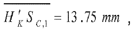
curve 8 of the length of the eye LE for a subject being 60 years old (AGE = 60). - On this figure, one can see that the eye length LE is comprised between around 20 mm and 28 mm.
- Moreover, one can see that the
curve 8 is a quasi straight line, showing that the eye length LE varies linearly with the need K in visual correction. - Finally, from this
figure 5 , one recovers the fact that, on one hand, a nearsighted eye (needing a negative power of correction, i.e. a divergent ophthalmic lens) is longer than the "normal" eye (needing no power of correction, K = 0), and, on the other end, a farsighted eye (needing a positive power of correction, i.e. a convergent ophthalmic lens) is shorter than the "normal" eye. -
Figure 6 shows a 3D plot of the position dERC of theERC 2 of theeye 1 of the subject as a function of age and need K (in diopters) of visual correction. - On this figure, one rediscovers that a myopic eye, needing negative correction (K < 0, divergent ophthalmic lens), is longer than a "normal" eye without such need (K = 0). The same is true for a hypermetropic eye (need K > 0; convergent ophthalmic lens) which is too short. For an age of 40 years, one sees that:
- the position dERC of the
ERC 2 of theeye 1 is around 13.5 mm for a "normal" eye (K = 0); and - the difference in the position dERC is as high as 2 mm (for an eye length of about 25 mm) for the two extreme cases (K = -6 δ and K = +6 δ).
- Preferably, after having determined a first approximate value of the position dERC of the
ERC 2 performing the different steps above, one then compares said first approximate value with a reference value dERC,ref, e.g. found in a geometrical database which stores an huge amount of measured values of the position dERC as function of age, need in visual correction, gender, and/or ethnicity, etc...; and one determines a second approximate value of said position of the eye rotation center based on the result of said comparison. - In practice, when the result of the comparison shows that the difference ΔdERC = |dERC - dERC,ref| between the approximate value dERC and the reference value dERC,ref is smaller than a predetermined threshold equal to 0.5 millimeter, preferably equal to 0.1 mm, the step of determining the second approximate value of the position of said eye comprises:
- feeding said first approximate value dERC to the geometrical database which stores values of the position of said eye rotation center of a plurality of subjects; and
- estimating said second approximate value as being equal to the first approximate value dERC.
- On the contrary, when the result of the comparison shows that the difference between the approximate value dERC and the reference value dERC,ref is larger than the predetermined threshold, determining the second approximate value of the position of said eye rotation center comprises:
- capturing, thanks to an image-capture device, at least two images of said eye while the individual looks in two different gaze directions;
- identifying, on each image, the image of the pupil of the eye and determining a geometrical feature of the image of the pupil linked to the shape of this image of the pupil; and
- determining said second approximate value as a function of said geometrical features of the image of the pupil determined for each image of said plurality of images.
- A description of this step of determining the second approximate value of the position of said eye rotation center may be found in the not-published
document EP 16 306 302.7


Claims (14)
- Method for determining a position (dERC) of the eye rotation center (2) of an eye (1) of a subject comprising:- providing a geometric model of an eye (1), whereby the position (DERC) of the eye rotation center (2) of this eye (1) is determined based on a set of personal parameters (LE, dAC, DI, AGE, K) including at least a first geometric dimension (DI) of the eye (1), each personal parameter (LE, dAC, DI, AGE, K) being distinct from said position of the eye rotation center (2) of the eye (1);- determining a value of each personal parameter (LE, dAC, DI, AGE, K) for the subject; and- determining a first approximate value of said position (dERC) of the eye rotation center (2) of the eye (1) of the subject in accordance with said geometric model based on the values of the personal parameters (LE, dAC, DI, AGE, K).
- Method according to claim 1, wherein said set of personal parameters (LE, dAC, DI, AGE, K) further comprises at least a second geometric dimension (LE) of the eye (1), said first geometric dimension (DI) being measured and said second geometric dimension being assessed.
- Method according to claim 2, wherein the step of assessing said second geometric dimension comprises an evaluation of at least one particular remaining geometric dimension of the eye (1) based on tabulated data comprising several entries, each entry comprising a value of said second geometric dimension in association with at least one corresponding personal characteristic of the subject.
- Method according to claim 3, wherein said corresponding personal characteristic comprises age (AGE), gender, and/or ethnicity of the subject.
- Method according to claim 2, wherein the step of assessing said second geometric dimension (LE) comprises an evaluation of said second geometric dimension (LE) of the eye (1) using an optical model allowing to determine said second geometric dimension (LE) based on an optical power (PE) of said eye (1) and a need (K) of visual correction for said subject.
- Method according to anyone of claims 1 to 5, wherein said first geometric dimension (DI) of said eye (1) comprises at least one of the following:- an outer diameter (DI) of an iris (18) of said eye (1);- a front and/or rear shape of a lens (20) of said eye (1); and/or- a distance (dAC) between a corneal apex (13) and said lens (20) of the eye (1) or a pupil (15) or a plane of the pupil (15) of said eye (1).
- Method according to anyone of claims 1 to 6, wherein said geometric model is a model of the sclera (30) and of the cornea (10) of the eye (1), said sclera (30) being modeled by a first sphere (C1) having a first radius (R1) and said cornea (10) being modeled by a second sphere (C2) having a second radius (R2), said first sphere (C1) and said second sphere (C2) having a first center (P1) and a second center (P2) respectively, said first center (P1) and said second center (P2) defining an optical axis (3) of said eye (1).
- Method according to anyone of claims 1 to 7, further comprising:- acquiring at least one facial image (4) of said eye (1) of the subject; and- processing the at least one facial image (4) to derive, from said at least one facial image (4), an outer diameter (DI) of an iris (18) of said eye (1) as said first geometric dimension of the eye (1).
- Method according to anyone of claims 1 to 8, further comprising:- comparing said first approximate value of the position (dERC) of the eye rotation center (2) with a reference value (dERC,ref); and- determining a second approximate value of said position (dERC) of the eye rotation center (2) based on the result of said comparison.
- Method according to claim 9, wherein, when the result of the comparison shows that the difference (ΔdERC) between the first approximate value and the reference value is larger than a predetermined threshold, determining the second approximate value of the position (dERC) of said eye rotation center (2) comprises:- capturing, thanks to an image-capture device, at least two images of said eye (1) while the subject looks in two different gaze directions;- identifying, on each image, the image of the pupil (15) of the eye (1) and determining a geometrical feature of the image of the pupil (15) linked to the shape of this image of the pupil (15); and- determining said second approximate value as a function of said geometrical features of the image of the pupil (15) determined for each image of said plurality of images.
- Method according to claim 9, wherein, when the result of the comparison shows that the difference (ΔdERC) between the approximate value and the reference value is smaller than a predetermined threshold, the step of determining the second approximate value of the position (dERC) of said eye rotation center (2) of the eye (1) comprises:- feeding said first approximate value to a geometrical database storing values of the position of said eye rotation center (2) of a plurality of subjects; and- estimating said second approximate value as being equal to the first approximate value.
- Method for calculating a personalized ophthalmic lens (6) for a subject comprising:- determining a first approximate value of the position (dERC) of the eye rotation center (2) of an eye (1) of the subject with a method of determination according to any one of claims 1 to 11;- comparing said first approximate value of the position (dERC) of the eye rotation center (2) with a reference value (dERC,ref); and- when the result of the comparison shows that the difference between the first approximate value and the reference value is smaller than a predetermined threshold, calculating the personalized ophthalmic lens (6) on the basis of the first approximate value of the position (dERC) of the eye rotation center (2) of the subject.
- Method according to anyone of claims 10 to 12, wherein said predetermined threshold is equal to 0.5 millimeter.
- Device for determining a position (dERC) of the eye rotation center (2) of an eye (1) of a subject comprising:- an image-capture apparatus configured to acquire at least one facial image (4) of said eye (1);- image-processing means configured to process said at least one facial image (4) to determine a measured value of an outer diameter (DI) of an iris (18) of said eye (1); and- calculation means configured to determine a first approximate value of said position (dERC) of the eye rotation center (2) as a function of said value of the outer diameter (DI) of the iris (18) of said eye (1) and of a geometric model of an eye whereby the position of the eye rotation center of the eye is determined based on a set of personal parameters including at least the outer diameter of the iris of the eye, each personal parameter being distinct from said position of the eye rotation center.
Priority Applications (6)
| Application Number | Priority Date | Filing Date | Title |
|---|---|---|---|
| EP17179209.6A EP3420887B1 (en) | 2017-06-30 | 2017-06-30 | Method for determining the position of the eye rotation center of the eye of a subject, and associated device |
| JP2019572556A JP7186733B2 (en) | 2017-06-30 | 2018-06-29 | Method and associated equipment for locating the eye's rotation point in a subject |
| CN201880042171.7A CN110785113B (en) | 2017-06-30 | 2018-06-29 | Method for determining the position of the center of rotation of the eye of a subject's eye and related device |
| PCT/EP2018/067574 WO2019002543A1 (en) | 2017-06-30 | 2018-06-29 | Method for determining the position of the eye rotation center of the eye of a subject, and associated device |
| EP18734564.0A EP3644825B1 (en) | 2017-06-30 | 2018-06-29 | Method for determining the position of the eye rotation center of the eye of a subject, and associated device |
| US16/624,461 US11333901B2 (en) | 2017-06-30 | 2018-06-29 | Method for determining the position of the eye rotation center of the eye of a subject, and associated device |
Applications Claiming Priority (1)
| Application Number | Priority Date | Filing Date | Title |
|---|---|---|---|
| EP17179209.6A EP3420887B1 (en) | 2017-06-30 | 2017-06-30 | Method for determining the position of the eye rotation center of the eye of a subject, and associated device |
Publications (2)
| Publication Number | Publication Date |
|---|---|
| EP3420887A1 true EP3420887A1 (en) | 2019-01-02 |
| EP3420887B1 EP3420887B1 (en) | 2025-01-29 |
Family
ID=59298245
Family Applications (2)
| Application Number | Title | Priority Date | Filing Date |
|---|---|---|---|
| EP17179209.6A Active EP3420887B1 (en) | 2017-06-30 | 2017-06-30 | Method for determining the position of the eye rotation center of the eye of a subject, and associated device |
| EP18734564.0A Active EP3644825B1 (en) | 2017-06-30 | 2018-06-29 | Method for determining the position of the eye rotation center of the eye of a subject, and associated device |
Family Applications After (1)
| Application Number | Title | Priority Date | Filing Date |
|---|---|---|---|
| EP18734564.0A Active EP3644825B1 (en) | 2017-06-30 | 2018-06-29 | Method for determining the position of the eye rotation center of the eye of a subject, and associated device |
Country Status (5)
| Country | Link |
|---|---|
| US (1) | US11333901B2 (en) |
| EP (2) | EP3420887B1 (en) |
| JP (1) | JP7186733B2 (en) |
| CN (1) | CN110785113B (en) |
| WO (1) | WO2019002543A1 (en) |
Cited By (1)
| Publication number | Priority date | Publication date | Assignee | Title |
|---|---|---|---|---|
| WO2024240783A1 (en) | 2023-05-25 | 2024-11-28 | Essilor International | Lens element |
Families Citing this family (8)
| Publication number | Priority date | Publication date | Assignee | Title |
|---|---|---|---|---|
| DE102017007974A1 (en) * | 2017-01-27 | 2018-08-02 | Rodenstock Gmbh | Assignment of an eye model for the optimization of spectacle lenses with measurement data |
| CN111771179B (en) | 2018-01-17 | 2025-05-27 | 奇跃公司 | Display system and method for determining registration between a display and a user's eyes |
| WO2019143844A1 (en) * | 2018-01-17 | 2019-07-25 | Magic Leap, Inc. | Eye center of rotation determination, depth plane selection, and render camera positioning in display systems |
| WO2020023542A1 (en) | 2018-07-24 | 2020-01-30 | Magic Leap, Inc. | Display systems and methods for determining registration between a display and eyes of a user |
| WO2020028867A1 (en) | 2018-08-03 | 2020-02-06 | Magic Leap, Inc. | Depth plane selection for multi-depth plane display systems by user categorization |
| AU2021323518B2 (en) | 2020-08-10 | 2026-01-15 | Shamir Optical Industry Ltd. | Lenses and methods for affecting the progression of myopia |
| US12373030B2 (en) * | 2022-11-16 | 2025-07-29 | Shenzhen GOODIX Technology Co., Ltd. | Optical sightline tracking for a wearable system |
| CN116958885B (en) * | 2023-09-19 | 2023-12-05 | 四川大学 | Correcting glasses wearing comfort evaluation method and system based on reading vision |
Citations (4)
| Publication number | Priority date | Publication date | Assignee | Title |
|---|---|---|---|---|
| US20130076884A1 (en) * | 2010-03-19 | 2013-03-28 | Fittingbox | Method and device for measuring an interpupillary distance |
| US20130083976A1 (en) * | 2011-10-03 | 2013-04-04 | Qualcomm Incorporated | Image-based head position tracking method and system |
| WO2015101737A1 (en) | 2014-01-02 | 2015-07-09 | Essilor International (Compagnie Generale D'optique) | Method for determining at least one geometric parameter of a customized glasses frame, and related method for determining the customized frame |
| EP2963482A1 (en) * | 2013-02-28 | 2016-01-06 | HOYA Corporation | Spectacle lens design system, supply system, design method, and production method |
Family Cites Families (32)
| Publication number | Priority date | Publication date | Assignee | Title |
|---|---|---|---|---|
| US4420228A (en) * | 1980-06-12 | 1983-12-13 | Humphrey Instruments, Inc. | Method and apparatus for analysis of corneal shape |
| JP3347514B2 (en) * | 1995-03-31 | 2002-11-20 | ホーヤ株式会社 | Eye optical system simulation device |
| FR2762098B1 (en) * | 1997-04-10 | 1999-05-21 | Essilor Int | TRANSPARENT ARTICLE WITH RADIAL REFRACTION INDEX GRADIENT AND ITS MANUFACTURING PROCESS |
| CA2344586C (en) * | 1998-10-02 | 2008-04-29 | Scientific Optics, Inc. | Method for diagnosing and improving vision |
| US6505936B1 (en) | 1999-10-05 | 2003-01-14 | Lasersight Technologies, Inc. | Ellipsoidal corneal modeling for estimation and reshaping |
| JP2001145613A (en) * | 1999-11-22 | 2001-05-29 | Oki Electric Ind Co Ltd | Camera device with distance measurement function |
| US6631990B2 (en) | 2001-01-03 | 2003-10-14 | Acmed, Inc. | System for measuring distances in the anterior chamber of the eye |
| US8317327B2 (en) * | 2005-03-16 | 2012-11-27 | Lc Technologies, Inc. | System and method for eyeball surface topography as a biometric discriminator |
| FR2884130B1 (en) * | 2005-04-08 | 2008-02-15 | Essilor Int | METHOD AND DEVICE FOR DETERMINING THE ROTATION CENTER OF AN EYE |
| US8862447B2 (en) | 2010-04-30 | 2014-10-14 | Amo Groningen B.V. | Apparatus, system and method for predictive modeling to design, evaluate and optimize ophthalmic lenses |
| WO2010028654A1 (en) | 2008-09-11 | 2010-03-18 | Iol Innovations Aps | System and method for determining and predicting iol power in situ |
| EP2392961B1 (en) * | 2009-01-30 | 2019-06-26 | HOYA Corporation | Method for evaluating eyeglass lens, method for designing eyeglass lens, and method for manufacturing eyeglass lens |
| DE102009010467A1 (en) * | 2009-02-26 | 2010-09-09 | Carl Zeiss Vision Gmbh | Method and device for determining the position of the ocular pivot point |
| ES2656358T3 (en) * | 2011-10-22 | 2018-02-26 | Alcon Pharmaceuticals Ltd. | Apparatus for monitoring one or more eye parameters |
| EP2669732A1 (en) * | 2012-05-30 | 2013-12-04 | ESSILOR INTERNATIONAL (Compagnie Générale d'Optique) | A method for providing a personalized spectacle lens optical system for a wearer |
| EP2880489B1 (en) * | 2012-07-31 | 2023-05-24 | Essilor International | Progressive ophthalmic lens |
| DE102012019473A1 (en) * | 2012-09-28 | 2014-06-12 | Carl Zeiss Meditec Ag | Method for reliably determining the axial length of an eye |
| US20150029322A1 (en) * | 2013-07-23 | 2015-01-29 | Qualcomm Incorporated | Method and computations for calculating an optical axis vector of an imaged eye |
| FR3012952B1 (en) * | 2013-11-08 | 2015-11-06 | Essilor Int | METHOD FOR DETERMINING AT LEAST ONE OPTICAL DESIGN PARAMETER OF A PROGRESSIVE OPHTHALMIC LENS |
| DE102013020706A1 (en) * | 2013-12-10 | 2015-06-11 | Carl Zeiss Meditec Ag | Method for optimized selection of the IOL to be implanted in an eye |
| WO2015117905A1 (en) * | 2014-02-04 | 2015-08-13 | Fraunhofer-Gesellschaft zur Förderung der angewandten Forschung e.V. | 3-d image analyzer for determining viewing direction |
| KR102212209B1 (en) * | 2014-04-10 | 2021-02-05 | 삼성전자주식회사 | Method, apparatus and computer readable recording medium for eye gaze tracking |
| US10247962B2 (en) * | 2014-04-14 | 2019-04-02 | Essilor International | Method of calculating an optical system of a progressive addition ophthalmic lens being arranged to output a supplementary image |
| AU2015255562A1 (en) * | 2014-05-08 | 2016-11-10 | Mimo Ag | Method for the acquisition of optical coherence tomography image data of retina tissue of an eye of a human subject |
| FR3021204A1 (en) * | 2014-05-20 | 2015-11-27 | Essilor Int | METHOD FOR DETERMINING AT LEAST ONE PARAMETER OF VISUAL BEHAVIOR OF AN INDIVIDUAL |
| JP2016106962A (en) * | 2014-12-09 | 2016-06-20 | キヤノン株式会社 | Ophthalmologic apparatus and control method thereof |
| JP6633468B2 (en) * | 2015-08-26 | 2020-01-22 | 株式会社トプコン | Blood flow measurement device |
| BR112018006370B1 (en) * | 2015-10-01 | 2022-10-25 | Carl Zeiss Vision International Gmbh | NON-CORRECTIVE SINGLE LENS GLASSES OR SAFETY HELMET, COMPUTER IMPLEMENTED METHOD TO DESIGN A ONE-PIECE SHIELD, METHOD TO MANUFACTURE A ONE-PIECE SHIELD AND COMPUTER READable STORAGE MEDIA |
| JP6631951B2 (en) * | 2015-12-18 | 2020-01-15 | 国立大学法人静岡大学 | Eye gaze detection device and eye gaze detection method |
| BR102016009093A2 (en) * | 2016-04-22 | 2017-10-31 | Sequoia Capital Ltda. | EQUIPMENT FOR ACQUISITION OF 3D IMAGE DATE OF A FACE AND AUTOMATIC METHOD FOR PERSONALIZED MODELING AND MANUFACTURE OF GLASS FRAMES |
| EP3479293A4 (en) * | 2016-06-29 | 2020-03-04 | Seeing Machines Limited | SYSTEMS AND METHODS FOR PERFORMING LOOK TRACKING |
| CN108876879B (en) * | 2017-05-12 | 2022-06-14 | 腾讯科技(深圳)有限公司 | Method and device for realizing human face animation, computer equipment and storage medium |
-
2017
- 2017-06-30 EP EP17179209.6A patent/EP3420887B1/en active Active
-
2018
- 2018-06-29 JP JP2019572556A patent/JP7186733B2/en active Active
- 2018-06-29 WO PCT/EP2018/067574 patent/WO2019002543A1/en not_active Ceased
- 2018-06-29 CN CN201880042171.7A patent/CN110785113B/en active Active
- 2018-06-29 US US16/624,461 patent/US11333901B2/en active Active
- 2018-06-29 EP EP18734564.0A patent/EP3644825B1/en active Active
Patent Citations (4)
| Publication number | Priority date | Publication date | Assignee | Title |
|---|---|---|---|---|
| US20130076884A1 (en) * | 2010-03-19 | 2013-03-28 | Fittingbox | Method and device for measuring an interpupillary distance |
| US20130083976A1 (en) * | 2011-10-03 | 2013-04-04 | Qualcomm Incorporated | Image-based head position tracking method and system |
| EP2963482A1 (en) * | 2013-02-28 | 2016-01-06 | HOYA Corporation | Spectacle lens design system, supply system, design method, and production method |
| WO2015101737A1 (en) | 2014-01-02 | 2015-07-09 | Essilor International (Compagnie Generale D'optique) | Method for determining at least one geometric parameter of a customized glasses frame, and related method for determining the customized frame |
Non-Patent Citations (2)
| Title |
|---|
| LEFOHN A. ET AL.: "An ocularist's approach to human iris synthesis", IEEE COMPUTER GRAPHICS AND APPLICATIONS, vol. 23, no. 6, November 2003 (2003-11-01), XP011103127 |
| TAN, BO: "Optical Modeling of Schematic Eyes and the Ophthalmic Applications", PHD DISSERTATION, 2009, Retrieved from the Internet <URL:http://trace.tennessee.edu/utk qraddiss/63> |
Cited By (1)
| Publication number | Priority date | Publication date | Assignee | Title |
|---|---|---|---|---|
| WO2024240783A1 (en) | 2023-05-25 | 2024-11-28 | Essilor International | Lens element |
Also Published As
| Publication number | Publication date |
|---|---|
| US11333901B2 (en) | 2022-05-17 |
| JP2020525228A (en) | 2020-08-27 |
| JP7186733B2 (en) | 2022-12-09 |
| EP3644825B1 (en) | 2024-08-14 |
| EP3644825A1 (en) | 2020-05-06 |
| US20200218087A1 (en) | 2020-07-09 |
| WO2019002543A1 (en) | 2019-01-03 |
| EP3420887B1 (en) | 2025-01-29 |
| CN110785113A (en) | 2020-02-11 |
| CN110785113B (en) | 2022-07-12 |
Similar Documents
| Publication | Publication Date | Title |
|---|---|---|
| EP3644825B1 (en) | Method for determining the position of the eye rotation center of the eye of a subject, and associated device | |
| JP6072176B2 (en) | Method and apparatus for determining eyeball fulcrum position | |
| JP5997351B2 (en) | Manufacturing method of spectacle lens | |
| US9664591B2 (en) | Eyeglass lens evaluation method, eyeglass lens design method, eyeglass lens manufacturing method, eyeglass lens manufacturing system, and eyeglass lens | |
| CN101686802B (en) | Apparatus and method for determining necessary correction of defective vision of eye | |
| EP1837699B1 (en) | Method for the determination of a progressive ophtalmic lens | |
| CN101057170B (en) | Method for designing spectacle lenses taking into account an individual's head and eye movement | |
| EP2342599B1 (en) | Method for determining the inset of a progressive addition lens | |
| EP2392961A1 (en) | Method for evaluating eyeglass lens, method for designing eyeglass lens, and method for manufacturing eyeglass lens | |
| JP6845795B2 (en) | How to determine the lens design of an optical lens suitable for the wearer | |
| EP2450738A1 (en) | Progressive power lens and progressive power lens design method | |
| CN106537231B (en) | Progressive ophthalmic lens, design method and system thereof, computer readable storage medium | |
| JP6785857B2 (en) | A refractive power determination device configured to determine the refractive power of an optical lens and a method for determining the refractive power of an optical lens. | |
| CN116209943A (en) | Lenses and methods for affecting myopia progression | |
| KR101644489B1 (en) | Method for heterophoria measuring | |
| EP4512304A2 (en) | Determining a lens shape for producing an optical lens for an eye of a person | |
| EP4491098A1 (en) | Device for determining a visual behaviour of a person | |
| CN113795785A (en) | Method and device for determining at least an optical characteristic of a progressive lens to be placed in a frame for vision correction of a subject | |
| KR20230059330A (en) | Machine learning-based eyeglasses ordering devices and methods with VR |
Legal Events
| Date | Code | Title | Description |
|---|---|---|---|
| PUAI | Public reference made under article 153(3) epc to a published international application that has entered the european phase |
Free format text: ORIGINAL CODE: 0009012 |
|
| STAA | Information on the status of an ep patent application or granted ep patent |
Free format text: STATUS: THE APPLICATION HAS BEEN PUBLISHED |
|
| AK | Designated contracting states |
Kind code of ref document: A1 Designated state(s): AL AT BE BG CH CY CZ DE DK EE ES FI FR GB GR HR HU IE IS IT LI LT LU LV MC MK MT NL NO PL PT RO RS SE SI SK SM TR |
|
| AX | Request for extension of the european patent |
Extension state: BA ME |
|
| STAA | Information on the status of an ep patent application or granted ep patent |
Free format text: STATUS: REQUEST FOR EXAMINATION WAS MADE |
|
| 17P | Request for examination filed |
Effective date: 20190701 |
|
| RBV | Designated contracting states (corrected) |
Designated state(s): AL AT BE BG CH CY CZ DE DK EE ES FI FR GB GR HR HU IE IS IT LI LT LU LV MC MK MT NL NO PL PT RO RS SE SI SK SM TR |
|
| STAA | Information on the status of an ep patent application or granted ep patent |
Free format text: STATUS: EXAMINATION IS IN PROGRESS |
|
| 17Q | First examination report despatched |
Effective date: 20210609 |
|
| P01 | Opt-out of the competence of the unified patent court (upc) registered |
Effective date: 20230525 |
|
| GRAP | Despatch of communication of intention to grant a patent |
Free format text: ORIGINAL CODE: EPIDOSNIGR1 |
|
| STAA | Information on the status of an ep patent application or granted ep patent |
Free format text: STATUS: GRANT OF PATENT IS INTENDED |
|
| INTG | Intention to grant announced |
Effective date: 20241007 |
|
| GRAS | Grant fee paid |
Free format text: ORIGINAL CODE: EPIDOSNIGR3 |
|
| GRAA | (expected) grant |
Free format text: ORIGINAL CODE: 0009210 |
|
| STAA | Information on the status of an ep patent application or granted ep patent |
Free format text: STATUS: THE PATENT HAS BEEN GRANTED |
|
| AK | Designated contracting states |
Kind code of ref document: B1 Designated state(s): AL AT BE BG CH CY CZ DE DK EE ES FI FR GB GR HR HU IE IS IT LI LT LU LV MC MK MT NL NO PL PT RO RS SE SI SK SM TR |
|
| REG | Reference to a national code |
Ref country code: GB Ref legal event code: FG4D |
|
| REG | Reference to a national code |
Ref country code: CH Ref legal event code: EP |
|
| REG | Reference to a national code |
Ref country code: DE Ref legal event code: R096 Ref document number: 602017087527 Country of ref document: DE |
|
| REG | Reference to a national code |
Ref country code: IE Ref legal event code: FG4D |
|
| REG | Reference to a national code |
Ref country code: NL Ref legal event code: MP Effective date: 20250129 |
|
| PG25 | Lapsed in a contracting state [announced via postgrant information from national office to epo] |
Ref country code: NL Free format text: LAPSE BECAUSE OF FAILURE TO SUBMIT A TRANSLATION OF THE DESCRIPTION OR TO PAY THE FEE WITHIN THE PRESCRIBED TIME-LIMIT Effective date: 20250129 |
|
| PG25 | Lapsed in a contracting state [announced via postgrant information from national office to epo] |
Ref country code: RS Free format text: LAPSE BECAUSE OF FAILURE TO SUBMIT A TRANSLATION OF THE DESCRIPTION OR TO PAY THE FEE WITHIN THE PRESCRIBED TIME-LIMIT Effective date: 20250429 |
|
| PG25 | Lapsed in a contracting state [announced via postgrant information from national office to epo] |
Ref country code: FI Free format text: LAPSE BECAUSE OF FAILURE TO SUBMIT A TRANSLATION OF THE DESCRIPTION OR TO PAY THE FEE WITHIN THE PRESCRIBED TIME-LIMIT Effective date: 20250129 |
|
| PG25 | Lapsed in a contracting state [announced via postgrant information from national office to epo] |
Ref country code: PL Free format text: LAPSE BECAUSE OF FAILURE TO SUBMIT A TRANSLATION OF THE DESCRIPTION OR TO PAY THE FEE WITHIN THE PRESCRIBED TIME-LIMIT Effective date: 20250129 |
|
| PG25 | Lapsed in a contracting state [announced via postgrant information from national office to epo] |
Ref country code: ES Free format text: LAPSE BECAUSE OF FAILURE TO SUBMIT A TRANSLATION OF THE DESCRIPTION OR TO PAY THE FEE WITHIN THE PRESCRIBED TIME-LIMIT Effective date: 20250129 |
|
| REG | Reference to a national code |
Ref country code: LT Ref legal event code: MG9D |
|
| PG25 | Lapsed in a contracting state [announced via postgrant information from national office to epo] |
Ref country code: IS Free format text: LAPSE BECAUSE OF FAILURE TO SUBMIT A TRANSLATION OF THE DESCRIPTION OR TO PAY THE FEE WITHIN THE PRESCRIBED TIME-LIMIT Effective date: 20250529 Ref country code: NO Free format text: LAPSE BECAUSE OF FAILURE TO SUBMIT A TRANSLATION OF THE DESCRIPTION OR TO PAY THE FEE WITHIN THE PRESCRIBED TIME-LIMIT Effective date: 20250429 |
|
| REG | Reference to a national code |
Ref country code: AT Ref legal event code: MK05 Ref document number: 1762602 Country of ref document: AT Kind code of ref document: T Effective date: 20250129 |
|
| PG25 | Lapsed in a contracting state [announced via postgrant information from national office to epo] |
Ref country code: HR Free format text: LAPSE BECAUSE OF FAILURE TO SUBMIT A TRANSLATION OF THE DESCRIPTION OR TO PAY THE FEE WITHIN THE PRESCRIBED TIME-LIMIT Effective date: 20250129 |
|
| PG25 | Lapsed in a contracting state [announced via postgrant information from national office to epo] |
Ref country code: PT Free format text: LAPSE BECAUSE OF FAILURE TO SUBMIT A TRANSLATION OF THE DESCRIPTION OR TO PAY THE FEE WITHIN THE PRESCRIBED TIME-LIMIT Effective date: 20250529 Ref country code: LV Free format text: LAPSE BECAUSE OF FAILURE TO SUBMIT A TRANSLATION OF THE DESCRIPTION OR TO PAY THE FEE WITHIN THE PRESCRIBED TIME-LIMIT Effective date: 20250129 |
|
| PG25 | Lapsed in a contracting state [announced via postgrant information from national office to epo] |
Ref country code: BG Free format text: LAPSE BECAUSE OF FAILURE TO SUBMIT A TRANSLATION OF THE DESCRIPTION OR TO PAY THE FEE WITHIN THE PRESCRIBED TIME-LIMIT Effective date: 20250129 Ref country code: GR Free format text: LAPSE BECAUSE OF FAILURE TO SUBMIT A TRANSLATION OF THE DESCRIPTION OR TO PAY THE FEE WITHIN THE PRESCRIBED TIME-LIMIT Effective date: 20250430 |
|
| PG25 | Lapsed in a contracting state [announced via postgrant information from national office to epo] |
Ref country code: AT Free format text: LAPSE BECAUSE OF FAILURE TO SUBMIT A TRANSLATION OF THE DESCRIPTION OR TO PAY THE FEE WITHIN THE PRESCRIBED TIME-LIMIT Effective date: 20250129 |
|
| PG25 | Lapsed in a contracting state [announced via postgrant information from national office to epo] |
Ref country code: SE Free format text: LAPSE BECAUSE OF FAILURE TO SUBMIT A TRANSLATION OF THE DESCRIPTION OR TO PAY THE FEE WITHIN THE PRESCRIBED TIME-LIMIT Effective date: 20250129 |
|
| PG25 | Lapsed in a contracting state [announced via postgrant information from national office to epo] |
Ref country code: SM Free format text: LAPSE BECAUSE OF FAILURE TO SUBMIT A TRANSLATION OF THE DESCRIPTION OR TO PAY THE FEE WITHIN THE PRESCRIBED TIME-LIMIT Effective date: 20250129 |
|
| PG25 | Lapsed in a contracting state [announced via postgrant information from national office to epo] |
Ref country code: DK Free format text: LAPSE BECAUSE OF FAILURE TO SUBMIT A TRANSLATION OF THE DESCRIPTION OR TO PAY THE FEE WITHIN THE PRESCRIBED TIME-LIMIT Effective date: 20250129 |
|
| PG25 | Lapsed in a contracting state [announced via postgrant information from national office to epo] |
Ref country code: EE Free format text: LAPSE BECAUSE OF FAILURE TO SUBMIT A TRANSLATION OF THE DESCRIPTION OR TO PAY THE FEE WITHIN THE PRESCRIBED TIME-LIMIT Effective date: 20250129 Ref country code: CZ Free format text: LAPSE BECAUSE OF FAILURE TO SUBMIT A TRANSLATION OF THE DESCRIPTION OR TO PAY THE FEE WITHIN THE PRESCRIBED TIME-LIMIT Effective date: 20250129 |
|
| PG25 | Lapsed in a contracting state [announced via postgrant information from national office to epo] |
Ref country code: RO Free format text: LAPSE BECAUSE OF FAILURE TO SUBMIT A TRANSLATION OF THE DESCRIPTION OR TO PAY THE FEE WITHIN THE PRESCRIBED TIME-LIMIT Effective date: 20250129 |
|
| PG25 | Lapsed in a contracting state [announced via postgrant information from national office to epo] |
Ref country code: SK Free format text: LAPSE BECAUSE OF FAILURE TO SUBMIT A TRANSLATION OF THE DESCRIPTION OR TO PAY THE FEE WITHIN THE PRESCRIBED TIME-LIMIT Effective date: 20250129 |
|
| REG | Reference to a national code |
Ref country code: DE Ref legal event code: R097 Ref document number: 602017087527 Country of ref document: DE |
|
| PLBE | No opposition filed within time limit |
Free format text: ORIGINAL CODE: 0009261 |
|
| STAA | Information on the status of an ep patent application or granted ep patent |
Free format text: STATUS: NO OPPOSITION FILED WITHIN TIME LIMIT |
|
| REG | Reference to a national code |
Ref country code: CH Ref legal event code: L10 Free format text: ST27 STATUS EVENT CODE: U-0-0-L10-L00 (AS PROVIDED BY THE NATIONAL OFFICE) Effective date: 20251210 |
|
| 26N | No opposition filed |
Effective date: 20251030 |
|
| REG | Reference to a national code |
Ref country code: CH Ref legal event code: H13 Free format text: ST27 STATUS EVENT CODE: U-0-0-H10-H13 (AS PROVIDED BY THE NATIONAL OFFICE) Effective date: 20260127 |
|
| PG25 | Lapsed in a contracting state [announced via postgrant information from national office to epo] |
Ref country code: MC Free format text: LAPSE BECAUSE OF FAILURE TO SUBMIT A TRANSLATION OF THE DESCRIPTION OR TO PAY THE FEE WITHIN THE PRESCRIBED TIME-LIMIT Effective date: 20250129 |
|
| PG25 | Lapsed in a contracting state [announced via postgrant information from national office to epo] |
Ref country code: LU Free format text: LAPSE BECAUSE OF NON-PAYMENT OF DUE FEES Effective date: 20250630 |
|
| REG | Reference to a national code |
Ref country code: BE Ref legal event code: MM Effective date: 20250630 |
|
| PG25 | Lapsed in a contracting state [announced via postgrant information from national office to epo] |
Ref country code: IE Free format text: LAPSE BECAUSE OF NON-PAYMENT OF DUE FEES Effective date: 20250630 |
|
| PG25 | Lapsed in a contracting state [announced via postgrant information from national office to epo] |
Ref country code: BE Free format text: LAPSE BECAUSE OF NON-PAYMENT OF DUE FEES Effective date: 20250630 |
|
| PG25 | Lapsed in a contracting state [announced via postgrant information from national office to epo] |
Ref country code: CH Free format text: LAPSE BECAUSE OF NON-PAYMENT OF DUE FEES Effective date: 20250630 |
|
| PG25 | Lapsed in a contracting state [announced via postgrant information from national office to epo] |
Ref country code: LT Free format text: LAPSE BECAUSE OF FAILURE TO SUBMIT A TRANSLATION OF THE DESCRIPTION OR TO PAY THE FEE WITHIN THE PRESCRIBED TIME-LIMIT Effective date: 20250129 |
|
| PGFP | Annual fee paid to national office [announced via postgrant information from national office to epo] |
Ref country code: GB Payment date: 20260629 Year of fee payment: 10 |
|
| PGFP | Annual fee paid to national office [announced via postgrant information from national office to epo] |
Ref country code: IT Payment date: 20260622 Year of fee payment: 10 |
|
| PGFP | Annual fee paid to national office [announced via postgrant information from national office to epo] |
Ref country code: DE Payment date: 20260629 Year of fee payment: 10 |
|
| PGFP | Annual fee paid to national office [announced via postgrant information from national office to epo] |
Ref country code: FR Payment date: 20260625 Year of fee payment: 10 |
|
| PG25 | Lapsed in a contracting state [announced via postgrant information from national office to epo] |
Ref country code: CY Free format text: LAPSE BECAUSE OF FAILURE TO SUBMIT A TRANSLATION OF THE DESCRIPTION OR TO PAY THE FEE WITHIN THE PRESCRIBED TIME-LIMIT Effective date: 20250129 |