EP3420838B1 - Wrap-around wire support for shoe - Google Patents
Wrap-around wire support for shoe Download PDFInfo
- Publication number
- EP3420838B1 EP3420838B1 EP18176163.6A EP18176163A EP3420838B1 EP 3420838 B1 EP3420838 B1 EP 3420838B1 EP 18176163 A EP18176163 A EP 18176163A EP 3420838 B1 EP3420838 B1 EP 3420838B1
- Authority
- EP
- European Patent Office
- Prior art keywords
- heel
- midsole
- shoe
- arch
- outsole
- Prior art date
- Legal status (The legal status is an assumption and is not a legal conclusion. Google has not performed a legal analysis and makes no representation as to the accuracy of the status listed.)
- Active
Links
- 239000000463 material Substances 0.000 claims description 62
- 230000002787 reinforcement Effects 0.000 claims description 39
- 239000000203 mixture Substances 0.000 claims 2
- 229920005983 Infinergy® Polymers 0.000 claims 1
- 210000002683 foot Anatomy 0.000 description 42
- 230000008878 coupling Effects 0.000 description 25
- 238000010168 coupling process Methods 0.000 description 25
- 238000005859 coupling reaction Methods 0.000 description 25
- 239000004433 Thermoplastic polyurethane Substances 0.000 description 17
- 229920002803 thermoplastic polyurethane Polymers 0.000 description 17
- 230000000694 effects Effects 0.000 description 11
- 238000000034 method Methods 0.000 description 10
- 239000004744 fabric Substances 0.000 description 7
- 229920002396 Polyurea Polymers 0.000 description 6
- BFMKFCLXZSUVPI-UHFFFAOYSA-N ethyl but-3-enoate Chemical compound CCOC(=O)CC=C BFMKFCLXZSUVPI-UHFFFAOYSA-N 0.000 description 6
- 239000006260 foam Substances 0.000 description 6
- 230000007246 mechanism Effects 0.000 description 6
- 230000002093 peripheral effect Effects 0.000 description 6
- 238000004026 adhesive bonding Methods 0.000 description 4
- 239000013305 flexible fiber Substances 0.000 description 4
- 108010084652 homeobox protein PITX1 Proteins 0.000 description 4
- 230000007423 decrease Effects 0.000 description 3
- 229920001971 elastomer Polymers 0.000 description 3
- 238000005516 engineering process Methods 0.000 description 3
- 239000000835 fiber Substances 0.000 description 3
- 238000004519 manufacturing process Methods 0.000 description 3
- 210000000452 mid-foot Anatomy 0.000 description 3
- 229920003023 plastic Polymers 0.000 description 3
- 239000004033 plastic Substances 0.000 description 3
- 239000005060 rubber Substances 0.000 description 3
- 229920002725 thermoplastic elastomer Polymers 0.000 description 3
- 239000000853 adhesive Substances 0.000 description 2
- 230000001070 adhesive effect Effects 0.000 description 2
- 239000004568 cement Substances 0.000 description 2
- 239000006261 foam material Substances 0.000 description 2
- 238000007373 indentation Methods 0.000 description 2
- 238000002347 injection Methods 0.000 description 2
- 239000007924 injection Substances 0.000 description 2
- 238000001746 injection moulding Methods 0.000 description 2
- 239000010985 leather Substances 0.000 description 2
- 239000011159 matrix material Substances 0.000 description 2
- 239000002245 particle Substances 0.000 description 2
- 239000004814 polyurethane Substances 0.000 description 2
- 239000004753 textile Substances 0.000 description 2
- 239000004604 Blowing Agent Substances 0.000 description 1
- 229920000049 Carbon (fiber) Polymers 0.000 description 1
- 229920001410 Microfiber Polymers 0.000 description 1
- 239000004677 Nylon Substances 0.000 description 1
- 229910000831 Steel Inorganic materials 0.000 description 1
- 239000004917 carbon fiber Substances 0.000 description 1
- 239000000470 constituent Substances 0.000 description 1
- 230000008602 contraction Effects 0.000 description 1
- 230000003247 decreasing effect Effects 0.000 description 1
- 230000001419 dependent effect Effects 0.000 description 1
- 238000010586 diagram Methods 0.000 description 1
- 210000004744 fore-foot Anatomy 0.000 description 1
- 238000003780 insertion Methods 0.000 description 1
- 230000037431 insertion Effects 0.000 description 1
- 239000002649 leather substitute Substances 0.000 description 1
- VNWKTOKETHGBQD-UHFFFAOYSA-N methane Chemical compound C VNWKTOKETHGBQD-UHFFFAOYSA-N 0.000 description 1
- 239000003658 microfiber Substances 0.000 description 1
- 229920001778 nylon Polymers 0.000 description 1
- 229920003226 polyurethane urea Polymers 0.000 description 1
- 239000003380 propellant Substances 0.000 description 1
- 230000004043 responsiveness Effects 0.000 description 1
- 238000009958 sewing Methods 0.000 description 1
- 230000035939 shock Effects 0.000 description 1
- 229910001220 stainless steel Inorganic materials 0.000 description 1
- 239000010935 stainless steel Substances 0.000 description 1
- 239000010959 steel Substances 0.000 description 1
- 239000013589 supplement Substances 0.000 description 1
- 239000004758 synthetic textile Substances 0.000 description 1
- XLYOFNOQVPJJNP-UHFFFAOYSA-N water Substances O XLYOFNOQVPJJNP-UHFFFAOYSA-N 0.000 description 1
- 238000010618 wire wrap Methods 0.000 description 1
Images


Classifications
-
- A—HUMAN NECESSITIES
- A43—FOOTWEAR
- A43B—CHARACTERISTIC FEATURES OF FOOTWEAR; PARTS OF FOOTWEAR
- A43B7/00—Footwear with health or hygienic arrangements
- A43B7/14—Footwear with health or hygienic arrangements with foot-supporting parts
- A43B7/1495—Footwear with health or hygienic arrangements with foot-supporting parts with arch-supports of the bracelet type
-
- A—HUMAN NECESSITIES
- A43—FOOTWEAR
- A43C—FASTENINGS OR ATTACHMENTS OF FOOTWEAR; LACES IN GENERAL
- A43C11/00—Other fastenings specially adapted for shoes
- A43C11/16—Fastenings secured by wire, bolts, or the like
- A43C11/165—Fastenings secured by wire, bolts, or the like characterised by a spool, reel or pulley for winding up cables, laces or straps by rotation
Definitions
- the invention is generally related to shoes used during sporting activities and, more particularly, to a pair of shoes having increased support and/or torsional control properties and features to optimize performance and other characteristics of the shoes during a particular sporting activity (e.g., golf).
- a particular sporting activity e.g., golf
- the golfer's weight begins to shift and by the time the golf ball is struck, the golfer's weight is again evenly distributed between the rear and front feet, or has started to shift more to the front foot.
- the finish position of the swing most of the golfer's weight is on the front foot with more weight on the outside (lateral side) of the front foot than the inside (medial side), and the heel of the golfer's back foot is elevated above the ground and faces rearwardly.
- the heel and most of the outsole of the golfer's rear shoe are off of the ground, with only the toe portion contacting the ground for balance.
- the golfer's feet make complex movements during a golf swing to keep the golfer balanced while generating torque and club head speed to strike the golf ball.
- significant forces in various directions are exerted on the left and right shoes.
- the shoes provide enhanced stability, traction and torsional control in order to withstand and react appropriately to these forces and maximize the performance of the golfer's footwork during the golf swing.
- Similar circumstances exist during other sports such as baseball (e.g., during a batter's swing) and track & field (e.g., during start and running on a track), for example.
- shoes e.g., arch support, torsion, flexibility, stiffness, weight, etc.
- various characteristics of shoes e.g., arch support, torsion, flexibility, stiffness, weight, etc.
- US 2014/0223779 A1 discloses an article of footwear including an upper with a heel region that extends posteriorly about the heel, a medial side, and a lateral side.
- the article of footwear also includes a sole structure.
- the article includes a longitudinal strand that extends along at least one of the medial side and the lateral side.
- the article includes an underfoot strand that is coupled to the longitudinal strand and that extends across the sole structure to extend between the lateral side and the medial side of the upper.
- the article includes a closure strand that is coupled to the longitudinal strand.
- the closure strand is configured to couple to the closure element such that tensioning of the closure element tensions the longitudinal strand, the underfoot strand, and the closure strand to selectively secure the article of footwear to the foot.
- the invention addresses the above and other needs by providing shoes with improved comfort, fit, stability and performance to a wearer of the shoes.
- a shoe in one embodiment, includes: an upper configured to receive therein a foot of a wearer of the shoe, the upper comprising a closure and a tongue configured to cover a top portion of the foot; at least one wire lace coupled to opposing edges of the closure and configured to pull the opposing edges of the closure closer together to tighten the closure around the foot, and configured to release and allow the opposing edges to move away from each other to loosen the closure around the foot; and at least one support wire coupled to the at least one wire lace, wherein the at least one support wire wraps around a lateral, bottom and medial side of the upper such that when the at least one wire lace tightens the closure around the foot, the at least one support wire tightens around the lateral, bottom and medial sides of the upper.
- the invention provides a golf shoe that includes: an upper configured to receive therein a foot of a wearer of the golf shoe, the upper comprising a closure and a tongue configured to cover a top portion of the foot; a reel assembly and at least one wire lace coupled to the reel assembly; a wrap-around saddle assembly comprising a saddle and at least one saddle wire coupled to the saddle, wherein the saddle wraps around a lateral, bottom and medial side of the upper and the at least one saddle wire is coupled to the at least one wire lace such that when the reel assembly is turned in a first direction, the saddle tightens around the lateral, bottom and medial sides of the upper; a sole comprising a front sole portion and a heel sole portion, wherein the saddle wraps around a middle portion of the bottom surface of the upper located between the front and heel sole portions; and a plurality of traction elements disposed on bottom surfaces of the front and heel sole portions.
- the invention is directed to a method of manufacturing a shoe, the method including: providing an upper configured to receive therein a foot of a wearer of the golf shoe, the upper comprising a closure and a tongue configured to cover a top portion of the foot; coupling a reel assembly to the tongue; coupling at least one wire lace to the reel assembly; wrapping a saddle around a lateral, bottom and medial side of the upper, wherein the saddle comprises at least one saddle wire coupled to the saddle; coupling the at least one saddle wire to the at least one wire lace such that when the reel assembly is turned in a first direction, the saddle tightens around the lateral, bottom and medial sides of the upper; coupling a front sole portion to a front portion of the bottom surface of the upper; and coupling a heel sole portion to a heel portion of the bottom surface of the upper, wherein the saddle wraps around a middle portion of the bottom surface of the upper located between the front and heel portions.
- FIG. 1 illustrates a perspective view of a left shoe 100, in accordance with one embodiment of the invention.
- the shoe 100 includes an upper 102 for covering a top surface of a wearer's foot and front sole portion 104 and a heel sole portion 106 each attached to respective bottom surfaces of the upper 102.
- the front sole portion 104 and the heel sole portion 106 are two separate sole portions that leave exposed a mid-portion of the upper 102.
- an arch midsole reinforcement structure 221 ( Fig. 8 ) is affixed to an arch portion of the bottom surface of the upper 102 to provide further support and stability to this region of the shoe, as shown in Figure 8 and described in further detail below.
- the upper 102 includes an opening 108 through which a wearer's foot (not shown) may be inserted, and a closure 110 that allows a top portion of the upper 102 to be expanded or widened for easier insertion of the wearer's foot and thereafter closed or tightened around the wearer's foot.
- a flexible tongue 112 forms part of the closure 110 and is fixed to an underside of the upper 102 near the bottom of the closure 110 and extends upwardly past a top portion of the closure 110 so as to cover a top surface of the wearer's foot that would otherwise be exposed.
- the tongue 112 provides a cushioning cover above a top surface of the wearer's foot around which the closure 110 may be tightened via a lacing system to snugly secure the shoe 100 around the wearer's foot after it has been inserted through opening 108.
- the shoe 100 includes a reel-based lacing system 114 to tighten and secure the closure 110 and tongue 112 around the wearer's foot, in accordance with one embodiment of the invention.
- the reel-based lacing system 114 includes a reel assembly 116, a wire lace 118, and lace guides 120 and 121.
- the reel assembly 116 is attached to a top portion of the tongue 112 and contains a spool member (not shown) for holding the wire lace 118.
- the wire lace 118 is threaded through the plurality of lace guides 120, which also function as coupling mechanisms 120 to couple the reel-based lacing system to a wrap-around saddle assembly 122, as described in further detail below.
- the reel assembly 116 When the reel assembly is turned in a predetermined direction (e.g., clockwise), the wire lace 118 is wound around the spool member and becomes shorter, thereby pulling the lace guides 120 and 121 on opposite sides of the closure 110 closer together to tighten the closure 110 around the wearer's foot.
- Reel-based lacing systems are known in the art and described, for example, in U.S. Patent Publications Nos. 2014/0123449 and 2013/0092780 , and U.S. Patent Nos. 8,516,662 and 8,468,657 .
- the reel assembly 116 includes a knob (e.g., knob 218 in U.S.
- Patent Publication No. 2014/0123449 that may be raised axially to disengage the knob from the spool member (e.g., spool member 216 in U.S. Patent Publication No. 2014/0123449 ) in order to allow the spool member to freewheel in a loosening direction to release the lace.
- the knob may be manually and incrementally turned in the loosening direction to gradually loosen the lacing system.
- the shoe 100 further includes the wrap-around saddle assembly 122 that forms a portion of the closure 110, and includes one or more wire loops 124 threaded through respective channels (not shown) of a saddle 126 that wraps around an underside of the upper 102, as discussed in further detail below.
- Each wire loop 124 is received within respective lace guide/coupling mechanisms 120 on opposite side edges of the saddle assembly 122 or closure 110.
- three wire loops 124 extend from a respective coupling mechanism 120 affixed to one side edge of the saddle 126 and wraps around the side and bottom surfaces of the upper 102 to be coupled to a corresponding coupling mechanism 120 affixed to the opposite side edge of the saddle 126.
- the wire lace 118 is also threaded through lace guides 121 affixed to opposite side edges of the closure near a top portion of the closure 110 to further tighten and secure the closure 110 around the wearer's foot.
- the reel assembly 116 is turned to tighten the wire lace 118 and the coupling mechanisms 120 and lace guides 121 on opposite sides of the saddle 126 and closure 110, respectively, are brought closer together, the wire loops 124 are pulled taut to tighten around a corresponding mid-portion of the wearer's foot that includes the arch of the foot.
- the wrap-around saddle assembly 122 in addition to forming a part of the closure 110, provides increased arch support, lateral stability, and a tighter fit around the middle portion of the wearer's foot, which decreases foot fatigue and thereby increases comfort and performance of the wearer's foot during a sporting activity.
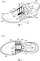
- Figure 2 illustrates a top view of a right shoe 100' corresponding to the left shoe 100 of Figure 1 , in accordance with one embodiment of the invention.
- the right shoe 100' has the same features discussed above with respect to the left shoe 100 of Figure 1 . These common features are designated with the same reference numerals as in Figure 1 .
- the wire lace 118 is laced in a traditional criss-cross pattern over the top of the tongue 112. It is understood, however, that any desired lacing pattern may be implemented in accordance with various embodiments of the invention.
- the wire lace 118 is secured to each side edge of the saddle 126 by a plurality (e.g., three) of coupling mechanisms 120 fixed to each side edge of the saddle 126 of the wrap-around saddle assembly 122.
- the wire lace 118 is further secured to lace guides 121 affixed to each side edge of the closure 110 near the top portion of the closure 110.
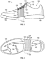
- Figures 3 and 4 illustrates side and bottom views, respectively, of the shoe 100 of Figure 1 , in accordance with one embodiment of the invention.
- the wire loops 124 and saddle 126 of saddle assembly 122 wrap around a bottom portion of the upper 102 that is located between the front sole portion 104 and the heel sole portion 106, where no sole is present.
- increased arch support and a tighter, custom fit of the shoe is provided.
- Increased arch support and a custom fit increases the comfort and responsiveness of the shoe and decreases foot fatigue that may be experienced by a wearer during a sporting activity.
- the front and heel soles 104 and 106 may include various grooves or indentations 140 in various patterns to provide enhanced flexibility, grip or traction to the bottom of the shoe 100. It is understood that any desired sole patterns may be implemented on the front and heel sole portions 104 and 106, respectively, in accordance with various embodiments of the invention. Additionally, cleats (not shown) may be fixed to the sole portions 104 and 106 in any desired configuration, number and size to provide increased gripping action on various surfaces such as natural or artificial turf, for example.
- FIG. 5 illustrates a perspective view of a wrap-around saddle assembly 122 when detached from the shoe 100, in accordance with one embodiment of the invention.
- the saddle assembly 122 includes the saddle 126 and a plurality (e.g., three) wire loops 124 that are threaded through respective channels 128 (indicated by dashed lines) in the saddle 126 such that each wire loop 124 traverses the entire length of the saddle 126 to extend outwardly from each corresponding end of the saddle 126 where they can be coupled to corresponding, opposing coupling members 120, as discussed above.
- a plurality e.g., three wire loops 124 that are threaded through respective channels 128 (indicated by dashed lines) in the saddle 126 such that each wire loop 124 traverses the entire length of the saddle 126 to extend outwardly from each corresponding end of the saddle 126 where they can be coupled to corresponding, opposing coupling members 120, as discussed above.
- each wire loop 124 need not extend across the entire underside of the shoe but, instead, may be fixed (e.g., stitched, glued, etc.) to respective edge portions of the saddle 126 such that when the wire loop 124 is pulled taut, as described above, the saddle 126 is also pulled taut around the foot of the wearer.
- at least a portion of the bottom portion 150 of the saddle 126 is fixed (e.g., stitched, glued, bonded, etc.) to a corresponding arch region of a bottom surface of the upper 102 ( Fig. 3 ), or to the arch midsole reinforcement structure 221 ( Fig. 8 ) so as to prevent undesired sliding or movement of the saddle 126 with respect to the upper 102 or arch midsole reinforcement structure 221.
- the saddle 126 may be made from various known materials or combination of materials and implemented in various configurations (e.g., size, shape, thickness, etc.).
- the saddle 126 reinforces the middle portion of the upper 102 and provides enhanced support and stability to this area of the shoe 100.
- the saddle 126 may be made from various materials known in the art, such as thermoplastic polyurethane or polyurea (TPU), rubber, leather, synthetic leather, textiles, and polyurethane or polyurea (PU), or carbon fiber, for example, or any combination of these materials to achieve desired strength, reinforcement and/or flexibility properties.
- TPU thermoplastic polyurethane or polyurea
- PU polyurethane or polyurea
- carbon fiber for example, or any combination of these materials to achieve desired strength, reinforcement and/or flexibility properties.
- Figure 6 illustrates a cross-sectional side view of a coupling member 120, in accordance with one embodiment of the invention.
- the coupling member 120 includes a first channel 160 through which wire lace 118 of reel-based lacing system 114 ( Fig. 1 ) may be threaded in accordance with known reel-based lacing techniques.
- the coupling member 120 further includes a second channel 162 into which a wire loop 124 may be inserted via slot 164.
- the slot 164 has a smaller height than a diameter of the second channel 162 such that once the wire loop 124 is inserted into the second channel 162, the smaller height of the slot 164 will prevent or resist movement of the wire loop 124 out of the second channel 162.
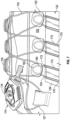
- FIG 7 illustrates a perspective close-up view of the reel-based lacing system 114 coupled to the wrap-around saddle assembly 122 via coupling members 120, as described above.
- the reel-based lacing system 114 includes a reel assembly 116 for reeling in or out a wire lace 118, which is received within respective first channels 160 of a plurality of coupling members 120.
- Each wire loop 124 of the saddle assembly 122 is also received within respective second channels 162 of the coupling member 120.
- the coupling members 120 couple the reel-based lacing system 114 to the wrap-around saddle assembly.
- each coupling member 120 is shown as partially transparent to reveal the wires contained within each coupling member 120.
- the saddle 126 is affixed onto the upper 102 by sewing the saddle 126 onto the upper 102 as shown by stitching 170. It is understood however, that the saddle 126 may be fixed or loosely coupled to one or more portions of the upper 102 in any desired fashion (e.g., stitching, gluing, bonding, etc.). As also shown in Figure 7 , longitudinal grooves formed in the saddle 126 form respective channels 172 between the saddle 126 and the underlying upper 102 through which respective portions of wire loops 124 may travel and wrap around the side and bottom portions of the upper 102. In one embodiment, the stitching 170 forms an exterior boundary for containing respective wire loops 124 within their respective channels 172.
- the wire loops 124 are tightened around the side and bottom portions of the upper 102 via the coupling members 120, thereby providing a tight fit around the arch and mid-foot area of the wearer.
- Figure 8 illustrates a side view of a golf shoe 200 in accordance with one embodiment of the invention.
- the golf shoe 200 has many similar features as the shoe 100 described above such as an upper 102, a reel assembly 116, wire laces 118, slightly modified coupling members 120' and lace guides 121', a wrap-around saddle assembly 122 having a plurality of wire loops 124 and a wrap-around saddle 126.
- these common elements and features will not be described again here.
- the golf shoe 200 further includes a sole 202 having a front sole portion 204, a heel sole portion 206 and an arch sole portion 208 that couples the front and heel sole portions 204 and 206 together, as described in further detail below.
- the front sole portion 204 includes a front midsole 210 that is sandwiched between a bottom surface of a front portion of the upper 102 and a front outsole 212 attached to a bottom surface of the front midsole 210.
- a front midsole reinforcement structure 214 is attached to a top portion of the front midsole 210 and surrounds an upper portion of the front midsole 210 where the front midsole 210 contacts the bottom surface of the upper 102.
- Portions of the front midsole reinforcement structure 214 are fixed to portions of the front outsole 212 to provide a reinforcement frame that surrounds the front midsole 210.
- the front midsole reinforcement structure 214 may be fixed to the front outsole 212 using any known technique (e.g., bonding, gluing, fastening with screws, etc.) or, alternatively, may be integrally formed together using known injection molding techniques.
- the front midsole reinforcement structure 214 and the front outsole can be made from a relatively dense ethyl vinyl acetate (EVA) or thermoplastic polyurethane (TPU) material that substantially prevents the respective portions of the front midsole 210 covered by the front midsole reinforcement structure 214 and the front outsole 212 from collapsing or substantially stretching in an outwardly direction, thereby providing increased strength and stability to the front midsole 210.
- EVA ethyl vinyl acetate
- TPU thermoplastic polyurethane
- the heel sole portion 206 includes a heel midsole 216 that is sandwiched between a bottom surface of a heel portion of the upper 102 and a heel outsole 218 attached to a bottom surface of the heel midsole 216.
- a heel midsole reinforcement structure 220 is attached to a top portion of the heel midsole 216 and surrounds an upper portion of the heel midsole 216 where the heel midsole 216 contacts the bottom surface of the heel portion of the upper 102.
- Portions of the heel midsole reinforcement structure 220 are fixed to portions of the heel outsole 218 to provide a reinforcement frame that surrounds the heel midsole 216.
- the heel midsole reinforcement structure 220 may be fixed to the heel outsole 218 using any known technique (e.g., bonding, gluing, fastening with screws, etc.) or, alternatively, may be integrally formed together using known injection molding techniques.
- the heel midsole reinforcement structure 220 and the heel outsole 218 can be made from a relatively dense ethyl vinyl acetate (EVA) or thermoplastic polyurethane (TPU) material that substantially prevents the respective portions of the heel midsole 216 covered by the heel midsole reinforcement structure 220 and the heel outsole 218 from collapsing or substantially stretching in an outwardly direction, thereby providing increased strength and stability to the heel midsole 216.
- EVA ethyl vinyl acetate
- TPU thermoplastic polyurethane
- the golf shoe 200 further includes an arch sole portion 208 comprising an arch outsole portion 219 that spans across and connects the front outsole portion 212 with the heel outsole portion 218, in accordance with one embodiment of the invention.
- the arch sole portion 208 further includes an arch midsole surrounded by an arch midsole reinforcement structure 221 and a window 222 between the arch midsole reinforcement structure and arch outsole portion 219, in accordance with one embodiment of the invention.
- the saddle 126 wraps around the arch midsole and reinforcement structure 221 such that the window 222 (i.e., a space of air) is formed between the bottom surface of the saddle 126 and the arch outsole portion 219, as shown in Figure 8 .
- the window 222 allows for the saddle 126 to completely wrap around the side and bottom surfaces of the upper 102, and further allows for the expansion and contraction of the saddle 126 as the wire laces 118 and wire loops 124 are loosened or tightened, as described above.
- the window 222 further allows for increased flexion to the arch region of the shoe 200, and torsion between the front and heel portions of the shoe 200. In other words, the front and heel portions can more readily twist with respect to one another.
- the arch outsole portion 219 (a.k.a., torsion control bridge) is provided, as described in further detail below.
- the arch outsole portion 219 provides further stability and torsion control to the middle section of the shoe 200 because it resists twisting of the front and heel portions of the upper 102 with respect to one another.
- a desired amount of torsion control can be achieved by adjusting the thickness, rigidity and/or physical material properties of the arch outsole portion 219.
- the arch outsole portion 219 allows for the full-length of the outsole to touch the ground and thus provides for traction along the full length of the shoe 200. It further provides an increased outsole surface area that contacts the ground, thereby providing increased traction while still allowing for a desired level of torsion/twisting of the shoe.
- the arch outsole portion 219 provides a torsion control bridge between the front and heel outsole portions 212 and 218, that allows the front and heel portions of the shoe 200 to move independently of one another to a desired degree, but not substantially beyond the desired amount.
- the arch outsole portion 219 further increases the length and surface area of the outsole that contacts the ground to provide increased traction during a sporting activity.
- both the arch midsole and its surround arch midsole reinforcement structure are collectively illustrated as the structure 221 since the arch midsole is contained within or surrounding by the arch midsole reinforcement structure.
- the arch midsole and surrounding arch midsole reinforcement structure 221 extends across a middle portion of the bottom surface of the upper 102 to provide further support and stability in the arch region of the shoe 200, in accordance with one embodiment of the invention.
- the arch midsole reinforcement structure 221 provides a relatively rigid frame or housing that surrounds and contains an arch midsole made from a relatively less rigid material (e.g., eTPU) located under the arch region of the upper 102.
- the wrap-around saddle 126 wraps around the arch midsole and arch midsole reinforcement structure 221 and, in one embodiment, is secured or affixed thereto.
- the front, heel and arch midsole reinforcement structures 214, 220 and 221, respectively, are integrally formed with one another and extend across substantially all of the bottom surface of upper 102, as shown in Figure 8 .
- the front and heel midsoles 210 and 216, as well as the arch midsole, discussed above can be made from an expanded TPU (eTPU) material (aka, Boost TM foam).
- eTPU expanded TPU
- Boost TM foam expanded TPU
- Such eTPU and other foams based on thermoplastic polyurethanes (TPU) suitable for use to form the midsole and/or outsole layers, in accordance with various embodiments, are described in further detail in U.S. Pat. App. Pub. No. 2010/0222442 A1 , which is incorporated by reference herein in its entirety.
- exemplary methods for production of eTPU using water as a blowing agent or propellant are described in U.S. Pat. App. Pub. No. 2012/0065285 A1 .
- the midsole layer can comprise a hybrid material comprising a matrix of PU and foamed particles of TPU or other thermoplastic elastomers, as described in U.S. Pat. App. Pub. No. 2010/0047550 A1 .
- Boost TM foam as a midsole material is that it is light weight and possesses superior energy-return or rebound properties that promote smooth energy transfer during the swing.
- the Boost TM foam also results in a lighter weight shoe, which further reduces fatigue to the wearer, especially if he or she is walking a golf course.
- the Boost TM foam also provides consistent and responsive cushioning across dynamic temperature ranges from subzero cold to punishing heat, thereby retaining its advantageous properties in any weather.
- the wrap-around saddle assembly 122 may be omitted and a shoe may utilize a traditional lacing system or reel-based lacing system.
- the arch outsole portion 219 can still function to provide enhanced traction, stability and torsion control to the shoe, as described above.
- the arch outsole portion 219 is integrally formed with the front and heel outsole portions 212 and 218, and made from the same outsole materials described above.
- the arch outsole portion 219 may be made from the same or a different material and mechanically attached to the front and heel outsole portions 212 and 216 such that it may be detached and interchanged with various different arch outsole portions (not shown) having different physical characteristics to achieve different desired performance characteristics of the shoe 200.
- Figure 9 illustrates a bottom surface of an outsole 250 that can be utilized in connection with the golf shoe 200 of Figure 8 , in accordance with one embodiment of the invention.
- the outsole 250 has a peripheral region 252 (shown as a darker region) that surrounds an interior region 254 (shown as a lighter region).
- the dimensions (e.g., thickness) and/or material(s) used to form the peripheral region 252 provide greater rigidity and durability when compared to the interior region 254.
- the greater rigidity and durability of the peripheral region 252 provides increased support and strength to the peripheral frame of the shoe 200 and allows for relatively larger traction elements 256 and 258 to be formed on or affixed to the peripheral region 252 of the outsole 250 to provide increased traction.
- a plurality of relatively smaller traction elements 260 extend outwardly from a bottom surface of the interior region 254 to provide further traction to supplement the traction provided by the larger traction elements 256 and 258 on the peripheral region 252.
- the interior region 254 further includes a plurality of holes 262 that allows the midsole material (e.g., Boost TM ) to expand through the holes 262, which allows for greater deformation of the midsole material and, hence, an enhanced "shock absorbing" property of the midsoles 210 and 216.
- the holes 262 also significantly decrease the weight of the interior region 254 of outsole 250, which reduces fatigue to a wearer, especially if they are walking long distances.
- the wrap around saddle assembly 122 comprising the saddle 126 and wire loops 124, is located directly above the arch outsole portion 219 with no midsole material sandwiched therebetween.
- a window of open space 222 ( Fig. 8 ) between the arch outsole portion 219 and the wrap-around saddle assembly 122 allows the saddle 126 and wire loops 124 to be completely wrapped around the side and bottom surfaces of the upper 102, and to be tightened or loosened using the reel-based lacing system 114 ( Fig. 1 ), as described above.
- the traction elements 256, 258 and 260 may be formed in various ways and made from various materials known in the art.
- the traction elements 256, 258 and 260 may be formed using GripMore TM technology, in which a plurality of cleat and/or traction elements may be attached to a bottom surface of a flexible fiber cloth or mesh textile lining that is cut and shaped to match the size and shape of each corresponding traction zone on a bottom surface of the outsole(s) 208, 212 and/or 218.
- GripMore TM technology is described in further detail in Taiwan Publication No. TW M412636U1 .
- the fiber cloth or mesh lining is fixedly adhered to a correspondingly sized and shaped indented bottom surface of the outsole corresponding to each respective traction zone.
- Multiple durometer plastic cleats are then injected into the fiber cloth so as to be permanently held in place by means of known techniques.
- the cleats which can be made of a highly durable TPR (thermoplastic rubber) are injected onto a lightweight but strong mesh textile lining and affixed with commercial grade adhesives for a secure bond.
- the mesh backing with injected cleats is then set into a predefined area in the outsole (commonly made from TPU) and glued in place to form the traction elements needed as per the sporting activity requirements.
- the flexible fiber cloth or mesh lining can be made from known plastics, rubber or other flexible, durable materials, or any combination of such materials.
- the cleats or traction elements can be made from suitable polyurethane (PU) materials.
- the flexible fiber cloth can be cut and shaped to be attached to premade indentations in the bottom surface of the outsole.
- the flexible fiber cloth can be permanently attached to the bottom surface of the outsole by any suitable means, such as gluing, bonding, etc.
- the Gripmore TM cleat technology provides many advantages for shoes requiring cleats.
- the fiber cloth can be ideally shaped, preformed and placed as desired without restriction to provide any cleat or traction element configuration. Additionally, since conventional cleat receptacle structures for receiving and securing a cleat therein are no longer required, the manufacturing cost and weight of the golf shoes are significantly decreased. Further, since cleat receptacle structures are no longer required, the size and placement of cleats on the bottom surface of the outsole are no longer limited by available space for the receptacle structures in the midsole layer.
- the various elements of the shoes described herein can be made from known suitable materials to achieve desired performance, durability and comfort characteristics, in accordance with various embodiments of the invention.
- the upper 102 may be made from a breathable micro fiber leather, or similar material, with varying thicknesses in various portions of the upper to achieve desired characteristics and properties.
- the outsoles discussed above may be made from an EVA or TPU material, and can be injection molded with one or more types of thermoplastic polyurethane (TPU).
- TPU thermoplastic polyurethane
- the midsoles discussed above can be formed by pouring PU or Boost TM foam material into respective TPU molds of the front and heel outsole portions.
- the soles described herein, comprising midsole and outsole layers can provide increased comfort and performance compared to conventional golf shoe soles having a single rigid platform that spans the sole and supports the traction elements in a dependent manner.
- the poured midsole can provide a durable yet soft and comfortable region below the golfer's foot and can bond directly to the injection molded outsole without cement or other rigid adhesion materials.
- the lower outsole can comprise a durable yet flexible material and can include various traction elements supported independently from one another such that they can flex and move separately throughout the golf swing, which results in more of the traction elements being in contact with the ground at any given time and allows the golfer's foot to have more freedom of motion and more comfort.
- the soles described herein can be lighter than conventional soles due to the use of lightweight polymeric materials, direct bonding of the constituent materials without cement, lack of other conventional platform components, and other properties.
- the midsole can be bonded directly to the outsole without an intermediate adhesive material.
- the midsole can comprise various foams and hybrid materials, such as a matrix of PU and foamed particles of TPU or eTPU.
- various soles and methods of making soles may be utilized in accordance with the present invention, such as those described in U.S. Patent Application Serial No. 14/513,582, filed on October 14, 2014 , claiming priority to U.S. Provisional Application Serial No. 61/896,442, filed on October 28, 2013 . It should be noted that in these previous applications, what is referred to as the "midsole” herein is referred to as the "upper outsole.”
- the sole of a golf shoe may be made from various material layers as described in U.S. Publication No. 2013/0291409 A1 .
- Boost TM foam material for the midsole
- other embodiments of the invention are not limited to using a particular type of material for the midsole, which can be made from any other suitable material such as TPU, Rubber, EVA, etc., or combination of such materials.
- the wire laces 118 and wire loops 124 may be made from any suitable material or combination of materials (e.g., steel, plastics, etc.) that have the desired strength and durability properties for a given activity.
- the wire laces 118 and 124 are made from nylon-coated stainless steel.
- the invention is not restricted to the illustrated exemplary designs, structures or configurations, but can be implemented using a variety of alternative designs, structures and configurations depending on the particular sporting activity (e.g., golf, baseball, track and field, etc.) or performance characteristics desired for a particular application.
Landscapes
- Health & Medical Sciences (AREA)
- Epidemiology (AREA)
- General Health & Medical Sciences (AREA)
- Public Health (AREA)
- Footwear And Its Accessory, Manufacturing Method And Apparatuses (AREA)
Description
- The invention is generally related to shoes used during sporting activities and, more particularly, to a pair of shoes having increased support and/or torsional control properties and features to optimize performance and other characteristics of the shoes during a particular sporting activity (e.g., golf).
- Many sporting activities today require shoes that provide enhanced stability, traction and performance to the athletes that wear them. For example, in golf, the golfer's footwork during the swing is complex and generates many different forces on the golfer's feet that must be absorbed, withstood and/or compensated for by the golfer's shoes. In general, for most golf shots the golfer's weight is initially loaded 50/50 on each foot and the golfer's weight is typically distributed evenly across the bottom surface area of each foot. During the backswing, a majority of the golfer's weight typically shifts to the outside (lateral side) of the golfer's back foot while the front foot maintains some weight for balance. The backswing applies forces tending to spin or pivot the back forefoot outwardly and the back heel inwardly, which must be resisted by the back foot's contact with the ground to keep the golfer's back foot stable.
- During the downswing of the club, the golfer's weight begins to shift and by the time the golf ball is struck, the golfer's weight is again evenly distributed between the rear and front feet, or has started to shift more to the front foot. At the finish position of the swing, most of the golfer's weight is on the front foot with more weight on the outside (lateral side) of the front foot than the inside (medial side), and the heel of the golfer's back foot is elevated above the ground and faces rearwardly. In a proper swing, only the toe portion of the golfer's rear foot remains in contact with the ground at the finish. Thus, in the finish position, the heel and most of the outsole of the golfer's rear shoe are off of the ground, with only the toe portion contacting the ground for balance.
- As discussed above, the golfer's feet make complex movements during a golf swing to keep the golfer balanced while generating torque and club head speed to strike the golf ball. During various stages of the golf swing, significant forces in various directions are exerted on the left and right shoes. Thus, it is desirable that the shoes provide enhanced stability, traction and torsional control in order to withstand and react appropriately to these forces and maximize the performance of the golfer's footwork during the golf swing. Similar circumstances exist during other sports such as baseball (e.g., during a batter's swing) and track & field (e.g., during start and running on a track), for example.
- In order to address the above exemplary needs, it is desirable to optimize various characteristics of shoes (e.g., arch support, torsion, flexibility, stiffness, weight, etc.) to provide the best comfort, fit, stability and performance to a wearer of the shoes, generally, and more particularly, to an athlete wearing the shoes during a sporting activity.
-
US 2014/0223779 A1 discloses an article of footwear including an upper with a heel region that extends posteriorly about the heel, a medial side, and a lateral side. The article of footwear also includes a sole structure. Moreover, the article includes a longitudinal strand that extends along at least one of the medial side and the lateral side. Also, the article includes an underfoot strand that is coupled to the longitudinal strand and that extends across the sole structure to extend between the lateral side and the medial side of the upper. Furthermore, the article includes a closure strand that is coupled to the longitudinal strand. The closure strand is configured to couple to the closure element such that tensioning of the closure element tensions the longitudinal strand, the underfoot strand, and the closure strand to selectively secure the article of footwear to the foot. - The underlying problem of the present invention is solved by the subject-matter of the independent claims.
- The invention addresses the above and other needs by providing shoes with improved comfort, fit, stability and performance to a wearer of the shoes.
- In one embodiment of the invention, a shoe is provided that includes: an upper configured to receive therein a foot of a wearer of the shoe, the upper comprising a closure and a tongue configured to cover a top portion of the foot; at least one wire lace coupled to opposing edges of the closure and configured to pull the opposing edges of the closure closer together to tighten the closure around the foot, and configured to release and allow the opposing edges to move away from each other to loosen the closure around the foot; and at least one support wire coupled to the at least one wire lace, wherein the at least one support wire wraps around a lateral, bottom and medial side of the upper such that when the at least one wire lace tightens the closure around the foot, the at least one support wire tightens around the lateral, bottom and medial sides of the upper.
- In another embodiment, the invention provides a golf shoe that includes: an upper configured to receive therein a foot of a wearer of the golf shoe, the upper comprising a closure and a tongue configured to cover a top portion of the foot; a reel assembly and at least one wire lace coupled to the reel assembly; a wrap-around saddle assembly comprising a saddle and at least one saddle wire coupled to the saddle, wherein the saddle wraps around a lateral, bottom and medial side of the upper and the at least one saddle wire is coupled to the at least one wire lace such that when the reel assembly is turned in a first direction, the saddle tightens around the lateral, bottom and medial sides of the upper; a sole comprising a front sole portion and a heel sole portion, wherein the saddle wraps around a middle portion of the bottom surface of the upper located between the front and heel sole portions; and a plurality of traction elements disposed on bottom surfaces of the front and heel sole portions.
- In a further embodiment, the invention is directed to a method of manufacturing a shoe, the method including: providing an upper configured to receive therein a foot of a wearer of the golf shoe, the upper comprising a closure and a tongue configured to cover a top portion of the foot; coupling a reel assembly to the tongue; coupling at least one wire lace to the reel assembly; wrapping a saddle around a lateral, bottom and medial side of the upper, wherein the saddle comprises at least one saddle wire coupled to the saddle; coupling the at least one saddle wire to the at least one wire lace such that when the reel assembly is turned in a first direction, the saddle tightens around the lateral, bottom and medial sides of the upper; coupling a front sole portion to a front portion of the bottom surface of the upper; and coupling a heel sole portion to a heel portion of the bottom surface of the upper, wherein the saddle wraps around a middle portion of the bottom surface of the upper located between the front and heel portions.
- In the following description of exemplary embodiments, reference is made to the following Figures which form a part hereof, and in which it is shown by way of illustration specific embodiments in which the invention may be made and practiced. It is to be understood that other embodiments may be utilized, and design and/or structural changes may be made, without departing from the scope of the invention. The Figures are provided for purposes of illustration only and merely depict exemplary embodiments of the invention to facilitate the reader's understanding of the invention and should not be considered limiting of the breadth, scope, or applicability of the invention. It should be noted that for clarity and ease of illustration these drawings are not necessarily drawn to scale.
-
Figure 1 is a perspective view of a left shoe, in accordance with one embodiment of the invention. -
Figure 2 is a top view of a right shoe corresponding to the left shoe ofFigure 1 , in accordance with one embodiment of the invention. -
Figure 3 is a side view of the shoe ofFigure 1 , in accordance with one embodiment of the invention. -
Figure 4 is a bottom view of the shoe ofFigure 1 , in accordance with one embodiment of the invention. -
Figure 5 is a perspective view of a wrap-around wire saddle, in accordance with one embodiment of the invention. -
Figure 6 is a cross-sectional side view of a coupling member having two wire loops contained therein, in accordance with one embodiment of the invention. -
Figure 7 illustrates a close-up view of a plurality of coupling members that couple a BOA reel-based lace system with the wrap-around wire saddle ofFigure 5 , in accordance with one embodiment of the invention. -
Figure 8 is a side view of a golf shoe, in accordance with one embodiment of the invention. -
Figure 9 is a bottom view of the golf shoe ofFigure 8 , in accordance with one embodiment of the invention. - In the following description of exemplary embodiments, reference is made to the accompanying drawings which form a part hereof, and in which it is shown by way of illustration of specific embodiments in which the invention may be practiced. It is to be understood that other embodiments may be utilized and structural changes may be made without departing from the scope of the invention. Although various embodiments and features of the invention are described below in the context of golf shoes, it will be apparent to those of ordinary skill in the art that various features and advantages of the invention can be applied to shoes used during other types of sporting activities.
-
Figure 1 illustrates a perspective view of aleft shoe 100, in accordance with one embodiment of the invention. Theshoe 100 includes an upper 102 for covering a top surface of a wearer's foot and frontsole portion 104 and a heelsole portion 106 each attached to respective bottom surfaces of the upper 102. As described in further detail below with reference toFigure 4 , in one embodiment, the frontsole portion 104 and the heelsole portion 106 are two separate sole portions that leave exposed a mid-portion of the upper 102. In an alternative embodiment, an arch midsole reinforcement structure 221 (Fig. 8 ) is affixed to an arch portion of the bottom surface of the upper 102 to provide further support and stability to this region of the shoe, as shown inFigure 8 and described in further detail below. - The upper 102 includes an
opening 108 through which a wearer's foot (not shown) may be inserted, and aclosure 110 that allows a top portion of the upper 102 to be expanded or widened for easier insertion of the wearer's foot and thereafter closed or tightened around the wearer's foot. Aflexible tongue 112 forms part of theclosure 110 and is fixed to an underside of the upper 102 near the bottom of theclosure 110 and extends upwardly past a top portion of theclosure 110 so as to cover a top surface of the wearer's foot that would otherwise be exposed. As is known in the art, thetongue 112 provides a cushioning cover above a top surface of the wearer's foot around which theclosure 110 may be tightened via a lacing system to snugly secure theshoe 100 around the wearer's foot after it has been inserted through opening 108. - As shown in
Figure 1 , theshoe 100 includes a reel-basedlacing system 114 to tighten and secure theclosure 110 andtongue 112 around the wearer's foot, in accordance with one embodiment of the invention. The reel-basedlacing system 114 includes areel assembly 116, awire lace 118, andlace guides reel assembly 116 is attached to a top portion of thetongue 112 and contains a spool member (not shown) for holding thewire lace 118. Thewire lace 118 is threaded through the plurality oflace guides 120, which also function ascoupling mechanisms 120 to couple the reel-based lacing system to a wrap-aroundsaddle assembly 122, as described in further detail below. When the reel assembly is turned in a predetermined direction (e.g., clockwise), thewire lace 118 is wound around the spool member and becomes shorter, thereby pulling thelace guides closure 110 closer together to tighten theclosure 110 around the wearer's foot. Reel-based lacing systems are known in the art and described, for example, inU.S. Patent Publications Nos. 2014/0123449 and2013/0092780 , andU.S. Patent Nos. 8,516,662 and8,468,657 . As disclosed inU.S. Patent Publication No. 2014/0123449 , for example, in some embodiments, thereel assembly 116 includes a knob (e.g.,knob 218 inU.S. Patent Publication No. 2014/0123449 ) that may be raised axially to disengage the knob from the spool member (e.g.,spool member 216 inU.S. Patent Publication No. 2014/0123449 ) in order to allow the spool member to freewheel in a loosening direction to release the lace. In other embodiments, the knob may be manually and incrementally turned in the loosening direction to gradually loosen the lacing system. - The
shoe 100 further includes the wrap-aroundsaddle assembly 122 that forms a portion of theclosure 110, and includes one ormore wire loops 124 threaded through respective channels (not shown) of asaddle 126 that wraps around an underside of the upper 102, as discussed in further detail below. Eachwire loop 124 is received within respective lace guide/coupling mechanisms 120 on opposite side edges of thesaddle assembly 122 orclosure 110. As shown inFigures 1-4 , in one embodiment, threewire loops 124 extend from arespective coupling mechanism 120 affixed to one side edge of thesaddle 126 and wraps around the side and bottom surfaces of the upper 102 to be coupled to acorresponding coupling mechanism 120 affixed to the opposite side edge of thesaddle 126. Thewire lace 118 is also threaded through lace guides 121 affixed to opposite side edges of the closure near a top portion of theclosure 110 to further tighten and secure theclosure 110 around the wearer's foot. When thereel assembly 116 is turned to tighten thewire lace 118 and thecoupling mechanisms 120 and lace guides 121 on opposite sides of thesaddle 126 andclosure 110, respectively, are brought closer together, thewire loops 124 are pulled taut to tighten around a corresponding mid-portion of the wearer's foot that includes the arch of the foot. Thus, the wrap-aroundsaddle assembly 122, in addition to forming a part of theclosure 110, provides increased arch support, lateral stability, and a tighter fit around the middle portion of the wearer's foot, which decreases foot fatigue and thereby increases comfort and performance of the wearer's foot during a sporting activity. -
Figure 2 illustrates a top view of a right shoe 100' corresponding to theleft shoe 100 ofFigure 1 , in accordance with one embodiment of the invention. The right shoe 100' has the same features discussed above with respect to theleft shoe 100 ofFigure 1 . These common features are designated with the same reference numerals as inFigure 1 . As shown inFigure 2 , thewire lace 118 is laced in a traditional criss-cross pattern over the top of thetongue 112. It is understood, however, that any desired lacing pattern may be implemented in accordance with various embodiments of the invention. Thewire lace 118 is secured to each side edge of thesaddle 126 by a plurality (e.g., three) ofcoupling mechanisms 120 fixed to each side edge of thesaddle 126 of the wrap-aroundsaddle assembly 122. Thewire lace 118 is further secured to lace guides 121 affixed to each side edge of theclosure 110 near the top portion of theclosure 110. When thereel assembly 116 is turned to tighten thewire lace 118, opposite side edges of thesaddle 126 and the top portion of theclosure 110 are brought closer together to tighten the upper 102 around the wearer's foot. Additionally, thewire loops 124 that wrap around the bottom of the mid-portion of the upper 102 tighten around the mid-portion and bottom arch of the foot to provide increased support and a more snug, custom fit around the wearer's foot. -
Figures 3 and 4 illustrates side and bottom views, respectively, of theshoe 100 ofFigure 1 , in accordance with one embodiment of the invention. As shown inFigures 3 and 4 , thewire loops 124 and saddle 126 ofsaddle assembly 122 wrap around a bottom portion of the upper 102 that is located between the frontsole portion 104 and the heelsole portion 106, where no sole is present. Thus, as thewire loops 124 are tightened around the mid-portion of the shoe, as described above, increased arch support and a tighter, custom fit of the shoe is provided. Increased arch support and a custom fit increases the comfort and responsiveness of the shoe and decreases foot fatigue that may be experienced by a wearer during a sporting activity. - As further shown in
Figure 4 , the front andheel soles indentations 140 in various patterns to provide enhanced flexibility, grip or traction to the bottom of theshoe 100. It is understood that any desired sole patterns may be implemented on the front and heelsole portions sole portions -
Figure 5 illustrates a perspective view of a wrap-aroundsaddle assembly 122 when detached from theshoe 100, in accordance with one embodiment of the invention. Thesaddle assembly 122 includes thesaddle 126 and a plurality (e.g., three)wire loops 124 that are threaded through respective channels 128 (indicated by dashed lines) in thesaddle 126 such that eachwire loop 124 traverses the entire length of thesaddle 126 to extend outwardly from each corresponding end of thesaddle 126 where they can be coupled to corresponding, opposingcoupling members 120, as discussed above. In an alternative embodiment, eachwire loop 124 need not extend across the entire underside of the shoe but, instead, may be fixed (e.g., stitched, glued, etc.) to respective edge portions of thesaddle 126 such that when thewire loop 124 is pulled taut, as described above, thesaddle 126 is also pulled taut around the foot of the wearer. In one embodiment, at least a portion of the bottom portion 150 of thesaddle 126 is fixed (e.g., stitched, glued, bonded, etc.) to a corresponding arch region of a bottom surface of the upper 102 (Fig. 3 ), or to the arch midsole reinforcement structure 221 (Fig. 8 ) so as to prevent undesired sliding or movement of thesaddle 126 with respect to the upper 102 or archmidsole reinforcement structure 221. - The
saddle 126 may be made from various known materials or combination of materials and implemented in various configurations (e.g., size, shape, thickness, etc.). Thesaddle 126 reinforces the middle portion of the upper 102 and provides enhanced support and stability to this area of theshoe 100. In various embodiments, thesaddle 126 may be made from various materials known in the art, such as thermoplastic polyurethane or polyurea (TPU), rubber, leather, synthetic leather, textiles, and polyurethane or polyurea (PU), or carbon fiber, for example, or any combination of these materials to achieve desired strength, reinforcement and/or flexibility properties. -
Figure 6 illustrates a cross-sectional side view of acoupling member 120, in accordance with one embodiment of the invention. As shown inFigure 6 , thecoupling member 120 includes afirst channel 160 through whichwire lace 118 of reel-based lacing system 114 (Fig. 1 ) may be threaded in accordance with known reel-based lacing techniques. Thecoupling member 120 further includes asecond channel 162 into which awire loop 124 may be inserted viaslot 164. Theslot 164 has a smaller height than a diameter of thesecond channel 162 such that once thewire loop 124 is inserted into thesecond channel 162, the smaller height of theslot 164 will prevent or resist movement of thewire loop 124 out of thesecond channel 162. -
Figure 7 illustrates a perspective close-up view of the reel-basedlacing system 114 coupled to the wrap-aroundsaddle assembly 122 viacoupling members 120, as described above. As shown inFigure 7 , the reel-basedlacing system 114 includes areel assembly 116 for reeling in or out awire lace 118, which is received within respectivefirst channels 160 of a plurality ofcoupling members 120. Eachwire loop 124 of thesaddle assembly 122 is also received within respectivesecond channels 162 of thecoupling member 120. Thus, thecoupling members 120 couple the reel-basedlacing system 114 to the wrap-around saddle assembly. InFigure 7 , eachcoupling member 120 is shown as partially transparent to reveal the wires contained within eachcoupling member 120. - In one embodiment, the
saddle 126 is affixed onto the upper 102 by sewing thesaddle 126 onto the upper 102 as shown by stitching 170. It is understood however, that thesaddle 126 may be fixed or loosely coupled to one or more portions of the upper 102 in any desired fashion (e.g., stitching, gluing, bonding, etc.). As also shown inFigure 7 , longitudinal grooves formed in thesaddle 126 formrespective channels 172 between thesaddle 126 and the underlying upper 102 through which respective portions ofwire loops 124 may travel and wrap around the side and bottom portions of the upper 102. In one embodiment, thestitching 170 forms an exterior boundary for containingrespective wire loops 124 within theirrespective channels 172. As discussed above, as thereel assembly 116 is turned to reel in thewire lace 118, thewire loops 124 are tightened around the side and bottom portions of the upper 102 via thecoupling members 120, thereby providing a tight fit around the arch and mid-foot area of the wearer. -
Figure 8 illustrates a side view of agolf shoe 200 in accordance with one embodiment of the invention. Thegolf shoe 200 has many similar features as theshoe 100 described above such as an upper 102, areel assembly 116, wire laces 118, slightly modified coupling members 120' and lace guides 121', a wrap-aroundsaddle assembly 122 having a plurality ofwire loops 124 and a wrap-aroundsaddle 126. For the sake of brevity, these common elements and features will not be described again here. - As shown in
Figure 8 , thegolf shoe 200 further includes a sole 202 having a frontsole portion 204, a heelsole portion 206 and an archsole portion 208 that couples the front and heelsole portions sole portion 204 includes afront midsole 210 that is sandwiched between a bottom surface of a front portion of the upper 102 and afront outsole 212 attached to a bottom surface of thefront midsole 210. A frontmidsole reinforcement structure 214 is attached to a top portion of thefront midsole 210 and surrounds an upper portion of thefront midsole 210 where thefront midsole 210 contacts the bottom surface of the upper 102. Portions of the frontmidsole reinforcement structure 214 are fixed to portions of thefront outsole 212 to provide a reinforcement frame that surrounds thefront midsole 210. The frontmidsole reinforcement structure 214 may be fixed to thefront outsole 212 using any known technique (e.g., bonding, gluing, fastening with screws, etc.) or, alternatively, may be integrally formed together using known injection molding techniques. In one embodiment, the frontmidsole reinforcement structure 214 and the front outsole can be made from a relatively dense ethyl vinyl acetate (EVA) or thermoplastic polyurethane (TPU) material that substantially prevents the respective portions of thefront midsole 210 covered by the frontmidsole reinforcement structure 214 and thefront outsole 212 from collapsing or substantially stretching in an outwardly direction, thereby providing increased strength and stability to thefront midsole 210. - Similarly, the heel
sole portion 206 includes aheel midsole 216 that is sandwiched between a bottom surface of a heel portion of the upper 102 and aheel outsole 218 attached to a bottom surface of theheel midsole 216. A heelmidsole reinforcement structure 220 is attached to a top portion of theheel midsole 216 and surrounds an upper portion of theheel midsole 216 where theheel midsole 216 contacts the bottom surface of the heel portion of the upper 102. Portions of the heelmidsole reinforcement structure 220 are fixed to portions of theheel outsole 218 to provide a reinforcement frame that surrounds theheel midsole 216. The heelmidsole reinforcement structure 220 may be fixed to theheel outsole 218 using any known technique (e.g., bonding, gluing, fastening with screws, etc.) or, alternatively, may be integrally formed together using known injection molding techniques. In one embodiment, the heelmidsole reinforcement structure 220 and theheel outsole 218 can be made from a relatively dense ethyl vinyl acetate (EVA) or thermoplastic polyurethane (TPU) material that substantially prevents the respective portions of theheel midsole 216 covered by the heelmidsole reinforcement structure 220 and theheel outsole 218 from collapsing or substantially stretching in an outwardly direction, thereby providing increased strength and stability to theheel midsole 216. - As further shown in
Figure 8 , thegolf shoe 200 further includes an archsole portion 208 comprising anarch outsole portion 219 that spans across and connects thefront outsole portion 212 with theheel outsole portion 218, in accordance with one embodiment of the invention. The archsole portion 208 further includes an arch midsole surrounded by an archmidsole reinforcement structure 221 and awindow 222 between the arch midsole reinforcement structure andarch outsole portion 219, in accordance with one embodiment of the invention. In one embodiment, thesaddle 126 wraps around the arch midsole andreinforcement structure 221 such that the window 222 (i.e., a space of air) is formed between the bottom surface of thesaddle 126 and thearch outsole portion 219, as shown inFigure 8 . Thewindow 222 allows for thesaddle 126 to completely wrap around the side and bottom surfaces of the upper 102, and further allows for the expansion and contraction of thesaddle 126 as the wire laces 118 andwire loops 124 are loosened or tightened, as described above. Thewindow 222 further allows for increased flexion to the arch region of theshoe 200, and torsion between the front and heel portions of theshoe 200. In other words, the front and heel portions can more readily twist with respect to one another. To offset and/or control the amount of torsion between the front and heel portions of theshoe 200, the arch outsole portion 219 (a.k.a., torsion control bridge) is provided, as described in further detail below. - The
arch outsole portion 219 provides further stability and torsion control to the middle section of theshoe 200 because it resists twisting of the front and heel portions of the upper 102 with respect to one another. A desired amount of torsion control can be achieved by adjusting the thickness, rigidity and/or physical material properties of thearch outsole portion 219. Further, thearch outsole portion 219 allows for the full-length of the outsole to touch the ground and thus provides for traction along the full length of theshoe 200. It further provides an increased outsole surface area that contacts the ground, thereby providing increased traction while still allowing for a desired level of torsion/twisting of the shoe. Thus, thearch outsole portion 219 provides a torsion control bridge between the front andheel outsole portions shoe 200 to move independently of one another to a desired degree, but not substantially beyond the desired amount. Thearch outsole portion 219 further increases the length and surface area of the outsole that contacts the ground to provide increased traction during a sporting activity. - In
Figure 8 , both the arch midsole and its surround arch midsole reinforcement structure are collectively illustrated as thestructure 221 since the arch midsole is contained within or surrounding by the arch midsole reinforcement structure. In one embodiment, the arch midsole and surrounding archmidsole reinforcement structure 221 extends across a middle portion of the bottom surface of the upper 102 to provide further support and stability in the arch region of theshoe 200, in accordance with one embodiment of the invention. The archmidsole reinforcement structure 221 provides a relatively rigid frame or housing that surrounds and contains an arch midsole made from a relatively less rigid material (e.g., eTPU) located under the arch region of the upper 102. The wrap-aroundsaddle 126 wraps around the arch midsole and archmidsole reinforcement structure 221 and, in one embodiment, is secured or affixed thereto. In one embodiment, the front, heel and archmidsole reinforcement structures Figure 8 . - In one embodiment, the front and
heel midsoles U.S. Pat. App. Pub. No. 2010/0222442 A1 , which is incorporated by reference herein in its entirety. Additionally, exemplary methods for production of eTPU using water as a blowing agent or propellant are described inU.S. Pat. App. Pub. No. 2012/0065285 A1 . In some embodiments, the midsole layer can comprise a hybrid material comprising a matrix of PU and foamed particles of TPU or other thermoplastic elastomers, as described inU.S. Pat. App. Pub. No. 2010/0047550 A1 . - Some exemplary advantages of using Boost™ foam as a midsole material is that it is light weight and possesses superior energy-return or rebound properties that promote smooth energy transfer during the swing. The Boost™ foam also results in a lighter weight shoe, which further reduces fatigue to the wearer, especially if he or she is walking a golf course. The Boost™ foam also provides consistent and responsive cushioning across dynamic temperature ranges from subzero cold to punishing heat, thereby retaining its advantageous properties in any weather.
- In an alternative embodiment, the wrap-around
saddle assembly 122 may be omitted and a shoe may utilize a traditional lacing system or reel-based lacing system. In this embodiment, thearch outsole portion 219 can still function to provide enhanced traction, stability and torsion control to the shoe, as described above. - In one embodiment the
arch outsole portion 219 is integrally formed with the front andheel outsole portions arch outsole portion 219 may be made from the same or a different material and mechanically attached to the front andheel outsole portions shoe 200. -
Figure 9 illustrates a bottom surface of anoutsole 250 that can be utilized in connection with thegolf shoe 200 ofFigure 8 , in accordance with one embodiment of the invention. As shown inFigure 9 , theoutsole 250 has a peripheral region 252 (shown as a darker region) that surrounds an interior region 254 (shown as a lighter region). In one embodiment, the dimensions (e.g., thickness) and/or material(s) used to form theperipheral region 252 provide greater rigidity and durability when compared to theinterior region 254. The greater rigidity and durability of theperipheral region 252 provides increased support and strength to the peripheral frame of theshoe 200 and allows for relativelylarger traction elements peripheral region 252 of theoutsole 250 to provide increased traction. - A plurality of relatively
smaller traction elements 260 extend outwardly from a bottom surface of theinterior region 254 to provide further traction to supplement the traction provided by thelarger traction elements peripheral region 252. Theinterior region 254 further includes a plurality ofholes 262 that allows the midsole material (e.g., Boost™) to expand through theholes 262, which allows for greater deformation of the midsole material and, hence, an enhanced "shock absorbing" property of themidsoles holes 262 also significantly decrease the weight of theinterior region 254 ofoutsole 250, which reduces fatigue to a wearer, especially if they are walking long distances. - As also shown in
Figure 9 , the wrap aroundsaddle assembly 122, comprising thesaddle 126 andwire loops 124, is located directly above thearch outsole portion 219 with no midsole material sandwiched therebetween. As discussed above, a window of open space 222 (Fig. 8 ) between thearch outsole portion 219 and the wrap-aroundsaddle assembly 122 allows thesaddle 126 andwire loops 124 to be completely wrapped around the side and bottom surfaces of the upper 102, and to be tightened or loosened using the reel-based lacing system 114 (Fig. 1 ), as described above. - In various embodiments the
traction elements traction elements TW M412636U1 - In one embodiment, the fiber cloth or mesh lining is fixedly adhered to a correspondingly sized and shaped indented bottom surface of the outsole corresponding to each respective traction zone. Multiple durometer plastic cleats are then injected into the fiber cloth so as to be permanently held in place by means of known techniques. For example, the cleats which can be made of a highly durable TPR (thermoplastic rubber) are injected onto a lightweight but strong mesh textile lining and affixed with commercial grade adhesives for a secure bond. The mesh backing with injected cleats is then set into a predefined area in the outsole (commonly made from TPU) and glued in place to form the traction elements needed as per the sporting activity requirements.
- In various embodiments, the flexible fiber cloth or mesh lining can be made from known plastics, rubber or other flexible, durable materials, or any combination of such materials. In various embodiments, the cleats or traction elements can be made from suitable polyurethane (PU) materials. The flexible fiber cloth can be cut and shaped to be attached to premade indentations in the bottom surface of the outsole. The flexible fiber cloth can be permanently attached to the bottom surface of the outsole by any suitable means, such as gluing, bonding, etc.
- The Gripmore™ cleat technology provides many advantages for shoes requiring cleats. The fiber cloth can be ideally shaped, preformed and placed as desired without restriction to provide any cleat or traction element configuration. Additionally, since conventional cleat receptacle structures for receiving and securing a cleat therein are no longer required, the manufacturing cost and weight of the golf shoes are significantly decreased. Further, since cleat receptacle structures are no longer required, the size and placement of cleats on the bottom surface of the outsole are no longer limited by available space for the receptacle structures in the midsole layer.
- The various elements of the shoes described herein can be made from known suitable materials to achieve desired performance, durability and comfort characteristics, in accordance with various embodiments of the invention. For example, in one embodiment, the upper 102 may be made from a breathable micro fiber leather, or similar material, with varying thicknesses in various portions of the upper to achieve desired characteristics and properties. As another example, the outsoles discussed above may be made from an EVA or TPU material, and can be injection molded with one or more types of thermoplastic polyurethane (TPU). The midsoles discussed above can be formed by pouring PU or Boost™ foam material into respective TPU molds of the front and heel outsole portions. Thus, the soles described herein, comprising midsole and outsole layers, can provide increased comfort and performance compared to conventional golf shoe soles having a single rigid platform that spans the sole and supports the traction elements in a dependent manner.
- The poured midsole can provide a durable yet soft and comfortable region below the golfer's foot and can bond directly to the injection molded outsole without cement or other rigid adhesion materials. The lower outsole can comprise a durable yet flexible material and can include various traction elements supported independently from one another such that they can flex and move separately throughout the golf swing, which results in more of the traction elements being in contact with the ground at any given time and allows the golfer's foot to have more freedom of motion and more comfort. Additionally, the soles described herein can be lighter than conventional soles due to the use of lightweight polymeric materials, direct bonding of the constituent materials without cement, lack of other conventional platform components, and other properties.
- In one embodiment, the midsole can be bonded directly to the outsole without an intermediate adhesive material. The midsole can comprise various foams and hybrid materials, such as a matrix of PU and foamed particles of TPU or eTPU. Various soles and methods of making soles may be utilized in accordance with the present invention, such as those described in
U.S. Patent Application Serial No. 14/513,582, filed on October 14, 2014 U.S. Provisional Application Serial No. 61/896,442, filed on October 28, 2013 U.S. Publication No. 2013/0291409 A1 . - Although various embodiments described above focus on the use of Boost™ foam material for the midsole, other embodiments of the invention are not limited to using a particular type of material for the midsole, which can be made from any other suitable material such as TPU, Rubber, EVA, etc., or combination of such materials.
- Additionally, other components or elements of the shoes described herein can be made from any suitable material or combination of materials using any technique known to those skilled in the art. For example, the wire laces 118 and
wire loops 124 may be made from any suitable material or combination of materials (e.g., steel, plastics, etc.) that have the desired strength and durability properties for a given activity. In one embodiment, the wire laces 118 and 124 are made from nylon-coated stainless steel. - Various exemplary embodiments of the invention have been described above to provide shoes having enhanced mid-foot and arch support and customizable fit and/or increased torsional control and traction under a mid-foot region of the shoe. It should be understood that the various embodiments described herein have been presented by way of example only, and not by way of limitation. Likewise, the various figures or diagrams presented depict an example design, structure or configuration, which is done to aid in understanding the concepts, features and functionality that can be included in various shoe pairs in accordance with one or more embodiments of the invention. The invention is not restricted to the illustrated exemplary designs, structures or configurations, but can be implemented using a variety of alternative designs, structures and configurations depending on the particular sporting activity (e.g., golf, baseball, track and field, etc.) or performance characteristics desired for a particular application.
- Additionally, it should be understood that the various features and functionality described in one or more of the individual embodiments are not limited in their applicability to the particular embodiment with which they are described, but instead can be applied, alone or in some combination, to one or more of the other embodiments of the invention, whether or not such embodiments are explicitly described and whether or not such features are presented as being a part of a particular described embodiment. Thus, the breadth and scope of the present invention should not be limited by any of the above-described exemplary embodiments but should be given a scope commensurate with the claims.
Claims (15)
- A shoe (100), comprising:an upper (102) configured to receive therein a foot of a wearer of the shoe (100), the upper (102) comprising a closure (110) and a tongue (112) configured to cover a top portion of the foot;a front sole portion (204) attached to a front portion of a bottom surface of the upper (102), the front sole portion (204) comprising a front midsole (210) made from a first material, a front outsole (212) made from a second material that is more rigid than the first material, and a front midsole reinforcement structure (214) made from a third material that is more rigid than the first material, the front midsole (210) being at least partially contained by the front midsole reinforcement structure (214) and the front outsole (212);a heel sole portion (206) attached to a heel portion of the bottom surface of the upper (102), the heel sole portion (206) comprising a heel midsole (216) made from the first material, a heel outsole (218) made from the second material, and a heel midsole reinforcement structure (220) made from the third material, the heel midsole (216) being at least partially contained by the heel midsole reinforcement structure (220) and the heel outsole (218);wherein at least one support wire (126) wraps around a middle portion of the bottom surface of the upper (102), wherein the middle portion is located between the front and heel portions; anda torsion control bridge (219) connecting the front and heel sole portions,characterised in that
a window (222) is formed between the torsion control bridge (219) and a portion of the bottom surface of the upper located between the front and heel sole portions. - The shoe (100) of claim 1, wherein the second and third materials have different compositions from one another.
- The shoe (100) of claim 2, wherein the first material comprises an expanded thermoplastic polyurethane, eTPU.
- The shoe (100) of claim 1, wherein the torsion control bridge comprises an arch outsole portion (219) disposed between the front and heel outsole portions and integrally formed with the front and heel outsole portions.
- The shoe (100) of claim 4, wherein the front and heel outsoles each comprise a medial portion and a lateral portion, wherein the medial portions of the front and heel outsoles are integrally formed with one another and the lateral portions of the front and heel outsoles are integrally formed with one another.
- The shoe (100) of claim 5, wherein the medial portions of the front and heel outsoles comprise a plurality a holes therein for allowing respective portions of the front and heel midsoles to expand there through.
- The shoe (100) of claim 4, further comprising a plurality of traction elements located on bottom surfaces of the front and heel outsoles.
- The shoe (100) of claim 1, further comprising:an arch midsole made from the first material and disposed between the front and heel midsoles; andan arch midsole reinforcement structure made from the third material and disposed between the front and heel midsole reinforcement structures, wherein the arch midsole reinforcement structure reinforces at least a portion of the arch midsole.
- The shoe (100) of claim 8, further comprising:a reel assembly coupled to the tongue;at least one wire lace coupled to the reel assembly and opposing edges of the closure such that when the reel assembly is turned in a first direction, the at least one wire lace pulls the opposing edges of the closure closer together and, when the reel assembly is turned in a second direction, the at least one wire lace releases and allows the opposing edges to move away from each other; anda wrap-around saddle assembly comprising a saddle and at least one saddle wire coupled to the saddle, wherein the saddle wraps around an arch portion of the upper located between the front and heel sole portions and the at least one saddle wire is coupled to the at least one wire lace such that when the reel assembly is turned in the first direction, the at least one saddle wire tightens the saddle around the arch portion of the upper and when the reel assembly is turned in the second direction, the at least one saddle wire loosens the saddle around the arch portion of the upper, and wherein the window is formed between a top surface of the torsion control bridge and a bottom surface of the saddle.
- A golf shoe (200), comprising:an upper (102) configured to receive therein a foot of a wearer of the shoe (200), the upper comprising a closure (110) and a tongue (112) configured to cover a top portion of the foot;a front sole portion (204) attached to a front portion of a bottom surface of the upper (102), the front sole portion comprising a front midsole (210) comprising a first material and a front outsole (212) comprising a second material that is more rigid than the first material,a front midsole reinforcement structure (214) comprising a third material that is more rigid than the first material, the front midsole (210) being at least partially contained by the front midsole reinforcement structure (214) and the front outsole (212);a heel sole portion (206) attached to a heel portion of the bottom surface of the upper (102), the heel sole portion (206) comprising a heel midsole (216) comprising the first material and a heel outsole (218) comprising the second material;a heel midsole reinforcement structure (220) comprising the third material, the heel midsole (216) being at least partially contained by the heel midsole reinforcement structure (220) and the heel outsole (218);wherein at least one support wire (126) wraps around a middle portion of the bottom surface of the upper (102), wherein the middle portion is located between the front and heel portions;an arch outsole (219) comprising the second material and connecting the front and heel outsoles, wherein a window (22) is formed between the arch outsole (219) and a portion of the bottom surface of the upper (102) located between the front and heel sole portions; anda plurality of traction elements (256, 258, 260) disposed on bottom surfaces of the front and heel outsoles.
- The golf shoe (200) of claim 10, further comprising an arch midsole made from the first material and disposed between the front and heel midsoles.
- The golf shoe (200) of claim 11, further comprising: an arch midsole reinforcement structure comprising the third material and disposed between the front and heel midsole reinforcement structures, wherein the arch midsole reinforcement structure reinforces at least a portion of the arch midsole.
- The golf shoe (200) of claim 10, wherein the second and third materials have different compositions from one another.
- The golf shoe (200) of claim 10, wherein the arch outsole is integrally formed with the front and heel outsoles.
- The golf shoe of claim 14, wherein the front and heel outsoles each comprise a medial portion and a lateral portion, wherein the medial portions of the front and heel outsoles are integrally formed with one another and the lateral portions of the front and heel outsoles are integrally formed with one another.
Applications Claiming Priority (2)
| Application Number | Priority Date | Filing Date | Title |
|---|---|---|---|
| US201562170353P | 2015-06-03 | 2015-06-03 | |
| EP16169112.6A EP3100629B1 (en) | 2015-06-03 | 2016-05-11 | Wrap-around wire support for shoe |
Related Parent Applications (1)
| Application Number | Title | Priority Date | Filing Date |
|---|---|---|---|
| EP16169112.6A Division EP3100629B1 (en) | 2015-06-03 | 2016-05-11 | Wrap-around wire support for shoe |
Publications (2)
| Publication Number | Publication Date |
|---|---|
| EP3420838A1 EP3420838A1 (en) | 2019-01-02 |
| EP3420838B1 true EP3420838B1 (en) | 2023-10-18 |
Family
ID=55963242
Family Applications (2)
| Application Number | Title | Priority Date | Filing Date |
|---|---|---|---|
| EP18176163.6A Active EP3420838B1 (en) | 2015-06-03 | 2016-05-11 | Wrap-around wire support for shoe |
| EP16169112.6A Active EP3100629B1 (en) | 2015-06-03 | 2016-05-11 | Wrap-around wire support for shoe |
Family Applications After (1)
| Application Number | Title | Priority Date | Filing Date |
|---|---|---|---|
| EP16169112.6A Active EP3100629B1 (en) | 2015-06-03 | 2016-05-11 | Wrap-around wire support for shoe |
Country Status (2)
| Country | Link |
|---|---|
| EP (2) | EP3420838B1 (en) |
| JP (1) | JP2016221232A (en) |
Families Citing this family (6)
| Publication number | Priority date | Publication date | Assignee | Title |
|---|---|---|---|---|
| JP2019000213A (en) * | 2017-06-13 | 2019-01-10 | キャラウェイ・ゴルフ・カンパニ | Shoe |
| JPWO2019073609A1 (en) * | 2017-10-13 | 2020-07-16 | 株式会社アシックス | Shoe soles and shoes |
| EP3727072A1 (en) * | 2017-12-22 | 2020-10-28 | Geox S.p.A. | Fastening device for a shoe |
| JP7303638B2 (en) * | 2019-02-14 | 2023-07-05 | トップゴルフ キャラウェイ ブランズ コーポレーション | shoes |
| US11844401B2 (en) | 2020-11-18 | 2023-12-19 | Acushnet Company | Article of footwear with closure system |
| WO2024170000A1 (en) * | 2024-03-26 | 2024-08-22 | 泉州市森晟鞋业有限公司 | System and method for connecting shoe functional component to shoe upper component |
Citations (1)
| Publication number | Priority date | Publication date | Assignee | Title |
|---|---|---|---|---|
| US20120023775A1 (en) * | 2005-05-19 | 2012-02-02 | Mark Reilly | Footwear with a shank system |
Family Cites Families (20)
| Publication number | Priority date | Publication date | Assignee | Title |
|---|---|---|---|---|
| US6289558B1 (en) * | 1997-08-22 | 2001-09-18 | Boa Technology, Inc. | Footwear lacing system |
| JP3238132B2 (en) * | 1998-10-02 | 2001-12-10 | 美津濃株式会社 | Midsole structure for sports shoes |
| JP2004016732A (en) * | 2002-06-20 | 2004-01-22 | Konsho Ryu | Shoes with winding device |
| WO2007082838A1 (en) | 2006-01-18 | 2007-07-26 | Basf Se | Foams based on thermoplastic polyurethanes |
| EP2109637B1 (en) | 2007-01-16 | 2018-07-25 | Basf Se | Hybrid systems consisting of foamed thermoplastic elastomers and polyurethanes |
| US8074379B2 (en) * | 2008-02-12 | 2011-12-13 | Acushnet Company | Shoes with shank and heel wrap |
| JP5129084B2 (en) * | 2008-10-23 | 2013-01-23 | ダンロップスポーツ株式会社 | Golf shoes |
| KR101688997B1 (en) | 2008-11-21 | 2016-12-22 | 보아 테크놀러지, 인크. | Reel based lacing system |
| WO2010136398A1 (en) | 2009-05-26 | 2010-12-02 | Basf Se | Water as a propellant for thermoplastics |
| US8479415B2 (en) * | 2010-03-30 | 2013-07-09 | Nike, Inc. | Article of footwear with a detachable wrap |
| US8387282B2 (en) * | 2010-04-26 | 2013-03-05 | Nike, Inc. | Cable tightening system for an article of footwear |
| DE112011101525B4 (en) | 2010-04-30 | 2020-07-09 | Boa Technology, Inc. | Retractor-based lacing system |
| US8875418B2 (en) * | 2011-02-04 | 2014-11-04 | Nike, Inc. | Tendon assembly for an article of footwear |
| TWM412636U (en) | 2011-03-25 | 2011-10-01 | Bing-Fang Li | golf shoes |
| US9101181B2 (en) | 2011-10-13 | 2015-08-11 | Boa Technology Inc. | Reel-based lacing system |
| DE102012206094B4 (en) | 2012-04-13 | 2019-12-05 | Adidas Ag | Soles for sports footwear, shoes and method of making a shoe sole |
| EP2916680B1 (en) | 2012-11-06 | 2018-12-26 | Boa Technology Inc. | Devices and methods for adjusting the fit of footwear |
| US9144263B2 (en) * | 2013-02-14 | 2015-09-29 | Nike, Inc. | Article of footwear with interconnected tensile strands |
| US9545128B2 (en) * | 2013-03-04 | 2017-01-17 | Nike, Inc. | Article of footwear incorporating a knitted component with tensile strand |
| KR102297325B1 (en) * | 2013-09-13 | 2021-09-03 | 보아 테크놀러지, 인크. | Reel based closure device and method therefore |
-
2015
- 2015-11-18 JP JP2015225553A patent/JP2016221232A/en active Pending
-
2016
- 2016-05-11 EP EP18176163.6A patent/EP3420838B1/en active Active
- 2016-05-11 EP EP16169112.6A patent/EP3100629B1/en active Active
Patent Citations (1)
| Publication number | Priority date | Publication date | Assignee | Title |
|---|---|---|---|---|
| US20120023775A1 (en) * | 2005-05-19 | 2012-02-02 | Mark Reilly | Footwear with a shank system |
Also Published As
| Publication number | Publication date |
|---|---|
| EP3100629A1 (en) | 2016-12-07 |
| JP2016221232A (en) | 2016-12-28 |
| EP3100629B1 (en) | 2018-06-27 |
| EP3420838A1 (en) | 2019-01-02 |
Similar Documents
| Publication | Publication Date | Title |
|---|---|---|
| US9788599B2 (en) | Torsion control bridge for shoe | |
| US9743709B2 (en) | Wrap-around wire support for shoe | |
| EP3420838B1 (en) | Wrap-around wire support for shoe | |
| US12042004B2 (en) | Articles of footwear transitional between a foot insertion or removal configuration and a foot supporting configuration | |
| US9713357B2 (en) | Asymmetric shoes | |
| US12114733B2 (en) | Golf shoes with lace tightening system for closure and comfortable fit | |
| US9907363B2 (en) | Strap securing systems for articles of footwear and other foot-receiving devices | |
| JP6072345B2 (en) | Footwear articles having a tensile structure | |
| US9326562B2 (en) | Outsole and sports shoe | |
| AU712111B2 (en) | Athletic shoe, especially soccer shoe | |
| CN104902773A (en) | Article of footwear having adjustable sole structure | |
| US9345283B2 (en) | Article of footwear with customizable stiffness | |
| US12167777B2 (en) | Golf shoes with lace tightening system for closure and comfortable fit | |
| US20140259766A1 (en) | Shoe Construction | |
| US7013586B1 (en) | Article of athletic footwear with a leash | |
| US20190231024A1 (en) | Foot Motion Control And/Or Stability Systems For Articles Of Footwear And Other Foot-Receiving Devices | |
| US20240099420A1 (en) | Golf shoes with lace tightening system for closure and comfortable fit | |
| KR102751850B1 (en) | Golf shoes with lace tightening system for closure and comfortable fit |
Legal Events
| Date | Code | Title | Description |
|---|---|---|---|
| PUAI | Public reference made under article 153(3) epc to a published international application that has entered the european phase |
Free format text: ORIGINAL CODE: 0009012 |
|
| STAA | Information on the status of an ep patent application or granted ep patent |
Free format text: STATUS: THE APPLICATION HAS BEEN PUBLISHED |
|
| AC | Divisional application: reference to earlier application |
Ref document number: 3100629 Country of ref document: EP Kind code of ref document: P |
|
| AK | Designated contracting states |
Kind code of ref document: A1 Designated state(s): AL AT BE BG CH CY CZ DE DK EE ES FI FR GB GR HR HU IE IS IT LI LT LU LV MC MK MT NL NO PL PT RO RS SE SI SK SM TR |
|
| STAA | Information on the status of an ep patent application or granted ep patent |
Free format text: STATUS: REQUEST FOR EXAMINATION WAS MADE |
|
| 17P | Request for examination filed |
Effective date: 20190702 |
|
| RBV | Designated contracting states (corrected) |
Designated state(s): AL AT BE BG CH CY CZ DE DK EE ES FI FR GB GR HR HU IE IS IT LI LT LU LV MC MK MT NL NO PL PT RO RS SE SI SK SM TR |
|
| STAA | Information on the status of an ep patent application or granted ep patent |
Free format text: STATUS: EXAMINATION IS IN PROGRESS |
|
| 17Q | First examination report despatched |
Effective date: 20210219 |
|
| STAA | Information on the status of an ep patent application or granted ep patent |
Free format text: STATUS: EXAMINATION IS IN PROGRESS |
|
| GRAP | Despatch of communication of intention to grant a patent |
Free format text: ORIGINAL CODE: EPIDOSNIGR1 |
|
| STAA | Information on the status of an ep patent application or granted ep patent |
Free format text: STATUS: GRANT OF PATENT IS INTENDED |
|
| INTG | Intention to grant announced |
Effective date: 20230509 |
|
| GRAS | Grant fee paid |
Free format text: ORIGINAL CODE: EPIDOSNIGR3 |
|
| GRAA | (expected) grant |
Free format text: ORIGINAL CODE: 0009210 |
|
| STAA | Information on the status of an ep patent application or granted ep patent |
Free format text: STATUS: THE PATENT HAS BEEN GRANTED |
|
| AC | Divisional application: reference to earlier application |
Ref document number: 3100629 Country of ref document: EP Kind code of ref document: P |
|
| AK | Designated contracting states |
Kind code of ref document: B1 Designated state(s): AL AT BE BG CH CY CZ DE DK EE ES FI FR GB GR HR HU IE IS IT LI LT LU LV MC MK MT NL NO PL PT RO RS SE SI SK SM TR |
|
| REG | Reference to a national code |
Ref country code: GB Ref legal event code: FG4D |
|
| REG | Reference to a national code |
Ref country code: CH Ref legal event code: EP |
|
| REG | Reference to a national code |
Ref country code: IE Ref legal event code: FG4D |
|
| REG | Reference to a national code |
Ref country code: DE Ref legal event code: R096 Ref document number: 602016083593 Country of ref document: DE |
|
| REG | Reference to a national code |
Ref country code: LT Ref legal event code: MG9D |
|
| REG | Reference to a national code |
Ref country code: NL Ref legal event code: MP Effective date: 20231018 |
|
| REG | Reference to a national code |
Ref country code: AT Ref legal event code: MK05 Ref document number: 1621614 Country of ref document: AT Kind code of ref document: T Effective date: 20231018 |
|
| PG25 | Lapsed in a contracting state [announced via postgrant information from national office to epo] |
Ref country code: NL Free format text: LAPSE BECAUSE OF FAILURE TO SUBMIT A TRANSLATION OF THE DESCRIPTION OR TO PAY THE FEE WITHIN THE PRESCRIBED TIME-LIMIT Effective date: 20231018 |
|
| PG25 | Lapsed in a contracting state [announced via postgrant information from national office to epo] |
Ref country code: GR Free format text: LAPSE BECAUSE OF FAILURE TO SUBMIT A TRANSLATION OF THE DESCRIPTION OR TO PAY THE FEE WITHIN THE PRESCRIBED TIME-LIMIT Effective date: 20240119 |
|
| PG25 | Lapsed in a contracting state [announced via postgrant information from national office to epo] |
Ref country code: IS Free format text: LAPSE BECAUSE OF FAILURE TO SUBMIT A TRANSLATION OF THE DESCRIPTION OR TO PAY THE FEE WITHIN THE PRESCRIBED TIME-LIMIT Effective date: 20240218 |
|
| PG25 | Lapsed in a contracting state [announced via postgrant information from national office to epo] |
Ref country code: LT Free format text: LAPSE BECAUSE OF FAILURE TO SUBMIT A TRANSLATION OF THE DESCRIPTION OR TO PAY THE FEE WITHIN THE PRESCRIBED TIME-LIMIT Effective date: 20231018 |
|
| PG25 | Lapsed in a contracting state [announced via postgrant information from national office to epo] |
Ref country code: AT Free format text: LAPSE BECAUSE OF FAILURE TO SUBMIT A TRANSLATION OF THE DESCRIPTION OR TO PAY THE FEE WITHIN THE PRESCRIBED TIME-LIMIT Effective date: 20231018 |
|
| PG25 | Lapsed in a contracting state [announced via postgrant information from national office to epo] |
Ref country code: ES Free format text: LAPSE BECAUSE OF FAILURE TO SUBMIT A TRANSLATION OF THE DESCRIPTION OR TO PAY THE FEE WITHIN THE PRESCRIBED TIME-LIMIT Effective date: 20231018 |
|
| PG25 | Lapsed in a contracting state [announced via postgrant information from national office to epo] |
Ref country code: LT Free format text: LAPSE BECAUSE OF FAILURE TO SUBMIT A TRANSLATION OF THE DESCRIPTION OR TO PAY THE FEE WITHIN THE PRESCRIBED TIME-LIMIT Effective date: 20231018 Ref country code: IS Free format text: LAPSE BECAUSE OF FAILURE TO SUBMIT A TRANSLATION OF THE DESCRIPTION OR TO PAY THE FEE WITHIN THE PRESCRIBED TIME-LIMIT Effective date: 20240218 Ref country code: GR Free format text: LAPSE BECAUSE OF FAILURE TO SUBMIT A TRANSLATION OF THE DESCRIPTION OR TO PAY THE FEE WITHIN THE PRESCRIBED TIME-LIMIT Effective date: 20240119 Ref country code: ES Free format text: LAPSE BECAUSE OF FAILURE TO SUBMIT A TRANSLATION OF THE DESCRIPTION OR TO PAY THE FEE WITHIN THE PRESCRIBED TIME-LIMIT Effective date: 20231018 Ref country code: BG Free format text: LAPSE BECAUSE OF FAILURE TO SUBMIT A TRANSLATION OF THE DESCRIPTION OR TO PAY THE FEE WITHIN THE PRESCRIBED TIME-LIMIT Effective date: 20240118 Ref country code: AT Free format text: LAPSE BECAUSE OF FAILURE TO SUBMIT A TRANSLATION OF THE DESCRIPTION OR TO PAY THE FEE WITHIN THE PRESCRIBED TIME-LIMIT Effective date: 20231018 Ref country code: PT Free format text: LAPSE BECAUSE OF FAILURE TO SUBMIT A TRANSLATION OF THE DESCRIPTION OR TO PAY THE FEE WITHIN THE PRESCRIBED TIME-LIMIT Effective date: 20240219 |
|
| PG25 | Lapsed in a contracting state [announced via postgrant information from national office to epo] |
Ref country code: SE Free format text: LAPSE BECAUSE OF FAILURE TO SUBMIT A TRANSLATION OF THE DESCRIPTION OR TO PAY THE FEE WITHIN THE PRESCRIBED TIME-LIMIT Effective date: 20231018 Ref country code: RS Free format text: LAPSE BECAUSE OF FAILURE TO SUBMIT A TRANSLATION OF THE DESCRIPTION OR TO PAY THE FEE WITHIN THE PRESCRIBED TIME-LIMIT Effective date: 20231018 Ref country code: PL Free format text: LAPSE BECAUSE OF FAILURE TO SUBMIT A TRANSLATION OF THE DESCRIPTION OR TO PAY THE FEE WITHIN THE PRESCRIBED TIME-LIMIT Effective date: 20231018 Ref country code: NO Free format text: LAPSE BECAUSE OF FAILURE TO SUBMIT A TRANSLATION OF THE DESCRIPTION OR TO PAY THE FEE WITHIN THE PRESCRIBED TIME-LIMIT Effective date: 20240118 Ref country code: LV Free format text: LAPSE BECAUSE OF FAILURE TO SUBMIT A TRANSLATION OF THE DESCRIPTION OR TO PAY THE FEE WITHIN THE PRESCRIBED TIME-LIMIT Effective date: 20231018 Ref country code: HR Free format text: LAPSE BECAUSE OF FAILURE TO SUBMIT A TRANSLATION OF THE DESCRIPTION OR TO PAY THE FEE WITHIN THE PRESCRIBED TIME-LIMIT Effective date: 20231018 |
|
| PGFP | Annual fee paid to national office [announced via postgrant information from national office to epo] |
Ref country code: GB Payment date: 20240418 Year of fee payment: 9 |
|
| PGFP | Annual fee paid to national office [announced via postgrant information from national office to epo] |
Ref country code: DE Payment date: 20240418 Year of fee payment: 9 |
|
| PG25 | Lapsed in a contracting state [announced via postgrant information from national office to epo] |
Ref country code: DK Free format text: LAPSE BECAUSE OF FAILURE TO SUBMIT A TRANSLATION OF THE DESCRIPTION OR TO PAY THE FEE WITHIN THE PRESCRIBED TIME-LIMIT Effective date: 20231018 |
|
| REG | Reference to a national code |
Ref country code: DE Ref legal event code: R097 Ref document number: 602016083593 Country of ref document: DE |
|
| PG25 | Lapsed in a contracting state [announced via postgrant information from national office to epo] |
Ref country code: CZ Free format text: LAPSE BECAUSE OF FAILURE TO SUBMIT A TRANSLATION OF THE DESCRIPTION OR TO PAY THE FEE WITHIN THE PRESCRIBED TIME-LIMIT Effective date: 20231018 |
|
| PG25 | Lapsed in a contracting state [announced via postgrant information from national office to epo] |
Ref country code: SK Free format text: LAPSE BECAUSE OF FAILURE TO SUBMIT A TRANSLATION OF THE DESCRIPTION OR TO PAY THE FEE WITHIN THE PRESCRIBED TIME-LIMIT Effective date: 20231018 |
|
| PG25 | Lapsed in a contracting state [announced via postgrant information from national office to epo] |
Ref country code: SM Free format text: LAPSE BECAUSE OF FAILURE TO SUBMIT A TRANSLATION OF THE DESCRIPTION OR TO PAY THE FEE WITHIN THE PRESCRIBED TIME-LIMIT Effective date: 20231018 Ref country code: SK Free format text: LAPSE BECAUSE OF FAILURE TO SUBMIT A TRANSLATION OF THE DESCRIPTION OR TO PAY THE FEE WITHIN THE PRESCRIBED TIME-LIMIT Effective date: 20231018 Ref country code: RO Free format text: LAPSE BECAUSE OF FAILURE TO SUBMIT A TRANSLATION OF THE DESCRIPTION OR TO PAY THE FEE WITHIN THE PRESCRIBED TIME-LIMIT Effective date: 20231018 Ref country code: IT Free format text: LAPSE BECAUSE OF FAILURE TO SUBMIT A TRANSLATION OF THE DESCRIPTION OR TO PAY THE FEE WITHIN THE PRESCRIBED TIME-LIMIT Effective date: 20231018 Ref country code: EE Free format text: LAPSE BECAUSE OF FAILURE TO SUBMIT A TRANSLATION OF THE DESCRIPTION OR TO PAY THE FEE WITHIN THE PRESCRIBED TIME-LIMIT Effective date: 20231018 Ref country code: DK Free format text: LAPSE BECAUSE OF FAILURE TO SUBMIT A TRANSLATION OF THE DESCRIPTION OR TO PAY THE FEE WITHIN THE PRESCRIBED TIME-LIMIT Effective date: 20231018 Ref country code: CZ Free format text: LAPSE BECAUSE OF FAILURE TO SUBMIT A TRANSLATION OF THE DESCRIPTION OR TO PAY THE FEE WITHIN THE PRESCRIBED TIME-LIMIT Effective date: 20231018 |
|
| PGFP | Annual fee paid to national office [announced via postgrant information from national office to epo] |
Ref country code: FR Payment date: 20240418 Year of fee payment: 9 |
|
| PLBE | No opposition filed within time limit |
Free format text: ORIGINAL CODE: 0009261 |
|
| STAA | Information on the status of an ep patent application or granted ep patent |
Free format text: STATUS: NO OPPOSITION FILED WITHIN TIME LIMIT |
|
| 26N | No opposition filed |
Effective date: 20240719 |
|
| PG25 | Lapsed in a contracting state [announced via postgrant information from national office to epo] |
Ref country code: SI Free format text: LAPSE BECAUSE OF FAILURE TO SUBMIT A TRANSLATION OF THE DESCRIPTION OR TO PAY THE FEE WITHIN THE PRESCRIBED TIME-LIMIT Effective date: 20231018 |
|
| PG25 | Lapsed in a contracting state [announced via postgrant information from national office to epo] |
Ref country code: SI Free format text: LAPSE BECAUSE OF FAILURE TO SUBMIT A TRANSLATION OF THE DESCRIPTION OR TO PAY THE FEE WITHIN THE PRESCRIBED TIME-LIMIT Effective date: 20231018 |
|
| REG | Reference to a national code |
Ref country code: CH Ref legal event code: PL |
|
| PG25 | Lapsed in a contracting state [announced via postgrant information from national office to epo] |
Ref country code: MC Free format text: LAPSE BECAUSE OF FAILURE TO SUBMIT A TRANSLATION OF THE DESCRIPTION OR TO PAY THE FEE WITHIN THE PRESCRIBED TIME-LIMIT Effective date: 20231018 |
|
| PG25 | Lapsed in a contracting state [announced via postgrant information from national office to epo] |
Ref country code: LU Free format text: LAPSE BECAUSE OF NON-PAYMENT OF DUE FEES Effective date: 20240511 |
|
| PG25 | Lapsed in a contracting state [announced via postgrant information from national office to epo] |
Ref country code: CH Free format text: LAPSE BECAUSE OF NON-PAYMENT OF DUE FEES Effective date: 20240531 |