EP3420770B1 - Passive intermodulation shaping - Google Patents
Passive intermodulation shaping Download PDFInfo
- Publication number
- EP3420770B1 EP3420770B1 EP17711258.8A EP17711258A EP3420770B1 EP 3420770 B1 EP3420770 B1 EP 3420770B1 EP 17711258 A EP17711258 A EP 17711258A EP 3420770 B1 EP3420770 B1 EP 3420770B1
- Authority
- EP
- European Patent Office
- Prior art keywords
- frame
- prbs
- ues
- pim
- node
- Prior art date
- Legal status (The legal status is an assumption and is not a legal conclusion. Google has not performed a legal analysis and makes no representation as to the accuracy of the status listed.)
- Active
Links
- 238000007493 shaping process Methods 0.000 title 1
- 238000000034 method Methods 0.000 claims description 19
- 230000005540 biological transmission Effects 0.000 claims description 17
- 238000013468 resource allocation Methods 0.000 claims description 8
- 230000007774 longterm Effects 0.000 claims description 3
- 101150071746 Pbsn gene Proteins 0.000 claims 12
- 230000000694 effects Effects 0.000 description 16
- 238000010586 diagram Methods 0.000 description 8
- 239000000969 carrier Substances 0.000 description 4
- 230000006870 function Effects 0.000 description 4
- 230000002411 adverse Effects 0.000 description 2
- 238000001228 spectrum Methods 0.000 description 2
- 101100297651 Mus musculus Pim2 gene Proteins 0.000 description 1
- 101001001642 Xenopus laevis Serine/threonine-protein kinase pim-3 Proteins 0.000 description 1
- 239000000654 additive Substances 0.000 description 1
- 230000001413 cellular effect Effects 0.000 description 1
- 230000007797 corrosion Effects 0.000 description 1
- 238000005260 corrosion Methods 0.000 description 1
- 230000007547 defect Effects 0.000 description 1
- 230000001419 dependent effect Effects 0.000 description 1
- 230000002045 lasting effect Effects 0.000 description 1
- 238000007726 management method Methods 0.000 description 1
- 238000004519 manufacturing process Methods 0.000 description 1
- 230000000704 physical effect Effects 0.000 description 1
- 230000035755 proliferation Effects 0.000 description 1
- 230000011664 signaling Effects 0.000 description 1
- 238000006467 substitution reaction Methods 0.000 description 1
Images


Classifications
-
- H—ELECTRICITY
- H04—ELECTRIC COMMUNICATION TECHNIQUE
- H04L—TRANSMISSION OF DIGITAL INFORMATION, e.g. TELEGRAPHIC COMMUNICATION
- H04L5/00—Arrangements affording multiple use of the transmission path
- H04L5/003—Arrangements for allocating sub-channels of the transmission path
- H04L5/0058—Allocation criteria
- H04L5/0062—Avoidance of ingress interference, e.g. ham radio channels
-
- H—ELECTRICITY
- H04—ELECTRIC COMMUNICATION TECHNIQUE
- H04W—WIRELESS COMMUNICATION NETWORKS
- H04W72/00—Local resource management
- H04W72/50—Allocation or scheduling criteria for wireless resources
- H04W72/54—Allocation or scheduling criteria for wireless resources based on quality criteria
- H04W72/541—Allocation or scheduling criteria for wireless resources based on quality criteria using the level of interference
-
- H—ELECTRICITY
- H04—ELECTRIC COMMUNICATION TECHNIQUE
- H04L—TRANSMISSION OF DIGITAL INFORMATION, e.g. TELEGRAPHIC COMMUNICATION
- H04L5/00—Arrangements affording multiple use of the transmission path
- H04L5/003—Arrangements for allocating sub-channels of the transmission path
- H04L5/0037—Inter-user or inter-terminal allocation
-
- H—ELECTRICITY
- H04—ELECTRIC COMMUNICATION TECHNIQUE
- H04L—TRANSMISSION OF DIGITAL INFORMATION, e.g. TELEGRAPHIC COMMUNICATION
- H04L5/00—Arrangements affording multiple use of the transmission path
- H04L5/003—Arrangements for allocating sub-channels of the transmission path
- H04L5/0058—Allocation criteria
- H04L5/0066—Requirements on out-of-channel emissions
-
- H—ELECTRICITY
- H04—ELECTRIC COMMUNICATION TECHNIQUE
- H04W—WIRELESS COMMUNICATION NETWORKS
- H04W72/00—Local resource management
- H04W72/04—Wireless resource allocation
-
- H—ELECTRICITY
- H04—ELECTRIC COMMUNICATION TECHNIQUE
- H04W—WIRELESS COMMUNICATION NETWORKS
- H04W72/00—Local resource management
- H04W72/50—Allocation or scheduling criteria for wireless resources
- H04W72/54—Allocation or scheduling criteria for wireless resources based on quality criteria
- H04W72/542—Allocation or scheduling criteria for wireless resources based on quality criteria using measured or perceived quality
-
- H—ELECTRICITY
- H04—ELECTRIC COMMUNICATION TECHNIQUE
- H04W—WIRELESS COMMUNICATION NETWORKS
- H04W72/00—Local resource management
- H04W72/50—Allocation or scheduling criteria for wireless resources
- H04W72/52—Allocation or scheduling criteria for wireless resources based on load
Definitions
- This disclosure relates to an apparatus for controlling radio resource allocation in a node of a radio access network.
- LTE Long-Term Evolution
- LTE-A Long-Term Evolution Advanced
- orthogonal frequency-division multiple access (OFDMA) scheme is used.
- OFDMA orthogonal frequency-division multiple access
- the physical channels and physical signals are mapped onto the OFDMA symbols and sub-carriers. These are grouped together into frames in which data is transmitted. Each frame is further divided into a plurality of physical resource blocks (PRBs).
- PRBs physical resource blocks
- a base station in the network known in LTE networks as an eNodeB, or eNB, allocates PRBs to the user equipment (UE) which may be utilised when sending data to the base station.
- UE user equipment
- the role of the LTE scheduler is to organise fitting data into the LTE frame. This organisation is complex, and is sensitive to factors including traffic volume, QoS requirements, and radio conditions.
- PIM passive intermodulation
- each of these frames will have a finite bandwidth running from a lower frequency 'L' to a higher frequency 'H', as shown in Figure 8B . Therefore the equations must be adjusted accordingly.
- f 1L ⁇ f 1H and f 2L ⁇ f 2H it is necessary to consider the four ranges of frequencies that will be affected by PIM.
- GB 2 508 383 A discloses a method of processing interference in a data stream carrying a plurality of uplink signals received in a wireless network, where the interference comprises a non-linear product of at least one downlink signal of the wireless network.
- the present disclosure provides an apparatus for controlling radio resource allocation in a node of a radio access network to minimize interference in a received uplink signal caused by passive intermodulation, PIM, between downlink signals for transmission by the same antenna in the same frame, comprising: a logical module configured for use in a scheduler for allocating physical resource blocks, PRBs, to plural user equipment, UE, in a frame for transmitting data to the UEs from a single antenna of the node, the logical module being configured to in use: receive channel quality indicators, CQIs, of PRB allocations for different UEs in the frame, determine suitable PRBs for each UE, based on the CQIs; and determine a PRB allocation for each UE from the suitable PRBs for each UE based on: in the time domain, minimizing the spread in time slots for each UE and in the frequency domain, maximizing the spread in frequency for each UE.
- a logical module configured for use in a scheduler for allocating physical resource blocks, PRBs, to plural
- the present disclosure provides a method for controlling radio resource allocation in a node of a radio access network to minimize interference in a received uplink signal caused by passive intermodulation, PIM, between downlink signals for transmission by the same antenna in the same frame, the method comprising the steps of: allocating physical resource blocks, PRBs, to plural user equipment, UE, in a downlink frame for transmitting data to the UEs from a single antenna of the node, receiving channel quality indicators, CQIs, of PRB allocations for different UEs in the frame, determining suitable PRBs for each UE, based on the CQIs, and determining a PRB allocation for each UE from the suitable PRBs for each UE based on: in the time domain, minimizing the spread in time slots for each UE, and in the frequency domain, maximizing the spread in frequency for each UE.
- the present disclosure provides a computer readable medium, optionally non-transitory, storing instructions which when executed by the one or more processors of the apparatus in the first aspect of the present disclosure, instantiate and operate the logical module.
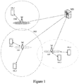
- Figure 1 provides a schematic diagram illustrating some basic functionality of a conventional mobile telecommunications network.
- the network includes a plurality of base stations 110 connected to a core network 120.
- the base stations 110 implement the Radio Access Network, which, under LTE enables packet switched voice and data communication between User Equipment 130 and a Core Network 120.
- Each base station 110 provides a coverage area 102 within which data can be communicated to and from UEs 130. Data is transmitted from base stations 110 to UEs 130 within their respective coverage areas 102 via a radio downlink. Data is transmitted from UEs 130 to the base stations 110 via a radio uplink.
- the core network 120 routes data to and from the UEs 130 via the respective base stations 110 and provides functions such as authentication, mobility management, charging and so on.
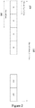
- FIG. 2 shows a schematic diagram illustrating an OFDM based LTE downlink radio frame 200.
- the LTE downlink radio frame 200 is transmitted from an LTE base station (known as an enhanced Node B, eNodeB, or eNB) and lasts 10 ms.
- the downlink radio frame comprises ten sub-frames 202, each sub-frame lasting 1 ms.
- Sub-frames 202 are themselves divided into two slots 204 (each 0.5ms). These slots are numbered to allow distinctions to be made between slots, thus Figure 3 shows slots #0, #1 ...#18, #19 in time order.
- Synchronisation signals are transmitted in certain sub-frames of the LTE radio frame to allow receiving UEs to maintain synchronisation with the radio transmissions of the eNB.
- an eNB may transmit different frames on different cells, each cell having the same bandwidth.
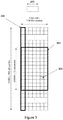
- Figure 3 is a schematic diagram of a grid which illustrates the structure of an example conventional downlink LTE slot 300.
- the horizontal axis represents time while the vertical represents frequency.
- the frequency axis is divided into a predetermined number of orthogonal sub-carriers, 15kHz each, distributed across the bandwidth of the downlink radio carrier, say 10MHz.
- the slot 300 comprises a predetermined number of "symbols" 306, which are transmitted during the 0.5 ms interval of the slot.
- the example slot 300 shown in Figure 3 comprises seven OFDM symbols 306 and six hundred sub-carriers (some of these are omitted for brevity) spread across a 10MHz bandwidth.
- the smallest allocation of user data for transmission in LTE is a "resource block" 302 comprising twelve sub-carriers transmitted over one slot.
- Control data may be allocated to smaller units known as resource elements, corresponding to a single sub-carrier of a given symbol - an example of a resource element is shown in Figure 3 , (reference sign - 304).
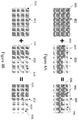
- Figures 4A and 4B are a simplified example of the PIM effects which two downlink frames may have on an uplink frame, where Figure 4B illustrates how the operation of a scheduler using apparatuses and methods of the present disclosure, can reduce the effects of interference due to PIM on performance of the Radio Access Network.
- the horizontal axis represents time, and the vertical axis represents frequency.
- each resource block 4021 within the frame has been allocated data by the scheduler.
- downlink frame 404 of a second cell only a portion 4041 of the frame has been allocated by the scheduler, wherein the remaining resource blocks 4042 do not comprise allocated resource blocks.
- the resource blocks allocated 4041 have been allocated so that they maximize the spread in time and minimize the spread in frequency.
- PIM may occur which affects the uplink frame 406 corresponding to the second cell.
- the resource blocks affected by PIM in the uplink frame 406 may be divided into two groups.
- the first group 4061 correlate to the resource blocks allocated 4041 in the downlink frame 404 relating to the second cell.
- the second group 4063 borders the first group 4061 in the frequency domain across the whole frame, this is because the effects of PIM are three times larger than the bandwidth of the transmission. Therefore the area not affected by PIM 4062 is reduced.
- the first group 4161 correlate to the resource blocks allocated 4141 in the downlink frame 414 relating to the second cell.
- the second group 4163 affected by PIM borders the first group 4161 in the frequency domain.
- the affected area of the second group 4163 borders only the frequencies of the first group 4161, and is limited in time to only the time slots contemporaneous with the first group 4161. Therefore the area not affected by PIM 4162 is increased compared to the area 4062 in Figure 4A , and, in accordance with aspects of the present disclosure, the effects of PIM can be minimised by configuring a scheduler to allocate resource blocks accordingly.
- Figure 5 illustrates an eNB base station used in the LTE environment.
- the eNB is responsible for the distribution of radio transmissions to all UEs on the downlink channels and receives transmissions from the UEs on the uplink channels. This is put into effect through combination of both analogue and digital signal processing functions.
- the eNB sends signaling messages to the UEs in order to control their operation, for example in relation to allocating resource blocks to be used in uplink communication.
- the eNB includes a scheduler for arranging data into resource blocks within a downlink frame.
- the scheduling of resource blocks may take into account various factors which many include any of: quality of service (QoS) reports, channel quality indicators (CQIs), buffer status, discontinuous reception (DRX) patterns, hybrid automatic repeat request (HARQ) acknowledgments and rank indications.
- QoS quality of service
- CQIs channel quality indicators
- DRX discontinuous reception
- HARQ hybrid automatic repeat request
- Each resource block may have an associated CQI.
- the CQI consists of 4-bits, these bits collectively indicate the maximum data rate that a UE is capable of managing with a resource block error ratio of 10% or less.
- the CQI is primarily calculated from the received signal to interference plus noise ratio (SINR). It may also depend on the configuration of the UE and its ability to process amounts of data.
- PIM occurs in a base station during the simultaneous transmission of data on different radio frequencies. Specifically within the LTE environment, it occurs an eNB when during the transmission of data in two different cells of the same bandwidth and of the same LTE frequency band, but in the same frame.
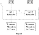
- Figure 5 of the present disclosure illustrates the relationship between the individual schedulers for each cell.
- Data 602, 604 for each cell is received by their respective schedulers 606, 608.
- the data may comprise any of: QoS reports, CQIs, buffer status, DRX patterns, HARQ acknowledgments and rank indications.
- first cell scheduler 506 and the second cell scheduler 508 may share information 507 such as CQIs.
- the schedulers 506, may use this information 507 to allocate resource blocks in their respective frames in order to reduce the effects of PIM.
- the scheduler 506, 507 may be implemented by software or hardware or a combination of the two.
- Figure 6 is a process flow diagram relating to the operation of the scheduler located in the eNB.
- step 602 the scheduler is initialised.
- step 604 the scheduler receives CQI reports from all the UEs which are in communication with the eNB. These CQI reports are subsequently stored, temporarily or permanently in the memory of the scheduler.
- step 606 using the data from the CQIs received from the respective UEs, the scheduler determines the resource blocks within a frame for each UE.
- step 608 the scheduler determines a resource block allocation within the frame in order to maximise the spread in frequency and minimize the spread in time. Furthermore, where optimal time and frequency resources overlap in a frame, in order to reconcile the overlap, the scheduler allocates subsets of resource blocks within the frame in order maximise the spread in frequency and minimize the spread in time.
- step 610 the scheduler repeats the aforementioned scheduling process for the next frame after the transmission time interval (TTI) of the existing frame has completed.
- TTI transmission time interval
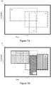
- Figures 7A and 7B relate to an example where suitable radio resources (PRBs) overlap in a frame.
- the illustrated frame 800 comprises the suitable time and frequency resources 802, 804, 806 for three UEs as determined from the received CQIs from each of the UEs. These three suitable resource allocations 802, 804 and 806 intersect and overlap at various areas across the frame 800.
- Figure 7B illustrates the application of the scheduler in accordance with the present disclosure on the frame 800 in order to reduce the effects of PIM.
- the resources For each of the respective suitable resources 802, 804, 806 the resources have been allocated 812, 814, 816 within the frame, generally and also when reconciling any overlap between the suitable resources, in order to maximize the range in frequency and minimize the range in time, thus reducing the effects of PIM.
Landscapes
- Engineering & Computer Science (AREA)
- Signal Processing (AREA)
- Computer Networks & Wireless Communication (AREA)
- Quality & Reliability (AREA)
- Mobile Radio Communication Systems (AREA)
Description
- This disclosure relates to an apparatus for controlling radio resource allocation in a node of a radio access network.
- The use of portable electronic devices for wireless data and voice communications for using a cellular telecommunications, such as one operating in accordance with the 4G Long-Term Evolution (LTE) or Long-Term Evolution Advanced (LTE-A) telecommunication standards have proliferated in recent years.
- In LTE and LTE-A compliant telecommunication networks, and orthogonal frequency-division multiple access (OFDMA) scheme is used. In this scheme, the physical channels and physical signals are mapped onto the OFDMA symbols and sub-carriers. These are grouped together into frames in which data is transmitted. Each frame is further divided into a plurality of physical resource blocks (PRBs). A base station in the network, known in LTE networks as an eNodeB, or eNB, allocates PRBs to the user equipment (UE) which may be utilised when sending data to the base station.
- The role of the LTE scheduler is to organise fitting data into the LTE frame. This organisation is complex, and is sensitive to factors including traffic volume, QoS requirements, and radio conditions.
- The increase of telecommunication usage has resulted in the number of frequency bands and amount of spectrum used in each band increasing considerably. This proliferation of telecommunication usage has often resulted in an associated decrease in system performance. It is desirable to adapt the operation of the Radio Access Network components to improve system performance, or at least to mitigate this reduction in system performance.
- It has been identified that one of the underlying factors for the decrease in performance is the result of passive intermodulation (PIM). It is in the above context in which PIM can adversely affect the performance of the network. PIM is an interference which occurs during the mixing of two or more frequencies by non-linear components when the frequencies are transmitted by the same antenna. PIM regularly occurs due to physical factors in the antenna, such as natural corrosion of the components, manufacturing defects and damage, poor connections at junctions and contaminated connections. Specifically within the LTE and LTE-A environments, multiple different frequency bands are often emitted from a single antenna, which renders it susceptible to the aforementioned physical effects.
- Although PIM occurs across many frequencies, interference is most severe at the third order product. For two single frequencies, f1 and f2, as shown in
Figure 8A , PIM is calculated as:

- In an environment with two transmissions, i.e., two downlink frames, in reality each of these frames will have a finite bandwidth running from a lower frequency 'L' to a higher frequency 'H', as shown in
Figure 8B . Therefore the equations must be adjusted accordingly. For two frequency bands f1L → f1H and f2L → f2H it is necessary to consider the four ranges of frequencies that will be affected by PIM. These are:


- Thus through overlap and substitution of these four ranges, the effective range and location of PIM occurring from two frames of the same bandwidth may be reduced to the following; which is effectively three times the bandwidth of the source.

- One of the effects of the number of frequency bands and amount of frequency spectrum used in each band increasing is that the bandwidths of PIM have also increased. Within the LTE and LTE-A environment, it has been shown that the resulting PIM from two or more downlink frames has particular adverse effects on uplink frames from a UE to the eNB.
- It is in this context that the present disclosure is devised.
-
GB 2 508 383 A - The invention is defined by the independent claims. Embodiments are defined by the dependent claims.
- Viewed from one aspect, the present disclosure provides an apparatus for controlling radio resource allocation in a node of a radio access network to minimize interference in a received uplink signal caused by passive intermodulation, PIM, between downlink signals for transmission by the same antenna in the same frame, comprising: a logical module configured for use in a scheduler for allocating physical resource blocks, PRBs, to plural user equipment, UE, in a frame for transmitting data to the UEs from a single antenna of the node, the logical module being configured to in use: receive channel quality indicators, CQIs, of PRB allocations for different UEs in the frame, determine suitable PRBs for each UE, based on the CQIs; and determine a PRB allocation for each UE from the suitable PRBs for each UE based on: in the time domain, minimizing the spread in time slots for each UE and in the frequency domain, maximizing the spread in frequency for each UE. The result of this is that the effect of PIM is reduced in uplink frames, therefore further resulting in less data loss and corruption and hence a more efficient telecommunications network.
- Viewed from another aspect, the present disclosure provides a method for controlling radio resource allocation in a node of a radio access network to minimize interference in a received uplink signal caused by passive intermodulation, PIM, between downlink signals for transmission by the same antenna in the same frame, the method comprising the steps of: allocating physical resource blocks, PRBs, to plural user equipment, UE, in a downlink frame for transmitting data to the UEs from a single antenna of the node, receiving channel quality indicators, CQIs, of PRB allocations for different UEs in the frame, determining suitable PRBs for each UE, based on the CQIs, and determining a PRB allocation for each UE from the suitable PRBs for each UE based on: in the time domain, minimizing the spread in time slots for each UE, and in the frequency domain, maximizing the spread in frequency for each UE.
- Viewed from another aspect, the present disclosure provides a computer readable medium, optionally non-transitory, storing instructions which when executed by the one or more processors of the apparatus in the first aspect of the present disclosure, instantiate and operate the logical module.
- Embodiments of the disclosure are further described hereinafter with reference to the accompanying drawings, in which:
-
Figure 1 provides a schematic diagram illustrating a conventional mobile telecommunications network. -
Figure 2 provides a schematic diagram illustrating a downlink frame. -
Figure 3 provides a schematic diagram of a grid which illustrates the structure of a conventional downlink slot. -
Figures 4A and 4B provide an example of the effects of PIM two downlink frames may have on an uplink frame, withFigure 4B being illustrative of the effect of embodiments of the present disclosure on reducing the impacts of PIM. -
Figure 5 provides a schematic diagram illustrating a base station and scheduler configuration across multiple cells. -
Figure 6 illustrates an embodiment of the process flow of the scheduler located in the base station configured and operating in accordance with apparatuses and methods of the present disclosure. -
Figures 7A and 7B provide an example embodiment of the operation of the scheduling algorithm in accordance with apparatuses and methods of the present disclosure to reduce interference due to PIM where optimal resources for multiple UEs overlap within the frame. -
Figures 8A and 8B illustrate single and finite bandwidth frequencies which can combine to produce interference through PIM. -
Figure 1 provides a schematic diagram illustrating some basic functionality of a conventional mobile telecommunications network. - The network includes a plurality of
base stations 110 connected to acore network 120. - The
base stations 110 implement the Radio Access Network, which, under LTE enables packet switched voice and data communication between User Equipment 130 and a Core Network 120. Eachbase station 110 provides acoverage area 102 within which data can be communicated to and from UEs 130. Data is transmitted frombase stations 110 to UEs 130 within theirrespective coverage areas 102 via a radio downlink. Data is transmitted from UEs 130 to thebase stations 110 via a radio uplink. Thecore network 120 routes data to and from the UEs 130 via therespective base stations 110 and provides functions such as authentication, mobility management, charging and so on. -
Figure 2 shows a schematic diagram illustrating an OFDM based LTEdownlink radio frame 200. Here, the horizontal axis represents time while the vertical represents frequency. The LTEdownlink radio frame 200 is transmitted from an LTE base station (known as an enhanced Node B, eNodeB, or eNB) and lasts 10 ms. The downlink radio frame comprises tensub-frames 202, each sub-frame lasting 1 ms.Sub-frames 202 are themselves divided into two slots 204 (each 0.5ms). These slots are numbered to allow distinctions to be made between slots, thusFigure 3 shows slots #0, #1 ...#18, #19 in time order. Synchronisation signals are transmitted in certain sub-frames of the LTE radio frame to allow receiving UEs to maintain synchronisation with the radio transmissions of the eNB. Within an operating frequency band, an eNB may transmit different frames on different cells, each cell having the same bandwidth. -
Figure 3 is a schematic diagram of a grid which illustrates the structure of an example conventionaldownlink LTE slot 300. As inFigure 2 , the horizontal axis represents time while the vertical represents frequency. The frequency axis is divided into a predetermined number of orthogonal sub-carriers, 15kHz each, distributed across the bandwidth of the downlink radio carrier, say 10MHz. Theslot 300 comprises a predetermined number of "symbols" 306, which are transmitted during the 0.5 ms interval of the slot. - The
example slot 300 shown inFigure 3 comprises sevenOFDM symbols 306 and six hundred sub-carriers (some of these are omitted for brevity) spread across a 10MHz bandwidth. The smallest allocation of user data for transmission in LTE is a "resource block" 302 comprising twelve sub-carriers transmitted over one slot. Control data may be allocated to smaller units known as resource elements, corresponding to a single sub-carrier of a given symbol - an example of a resource element is shown inFigure 3 , (reference sign - 304). -
Figures 4A and 4B are a simplified example of the PIM effects which two downlink frames may have on an uplink frame, whereFigure 4B illustrates how the operation of a scheduler using apparatuses and methods of the present disclosure, can reduce the effects of interference due to PIM on performance of the Radio Access Network. The horizontal axis represents time, and the vertical axis represents frequency. - In
Figure 4A , in thedownlink frame 402 of a first cell, everyresource block 4021 within the frame has been allocated data by the scheduler. Indownlink frame 404 of a second cell, only aportion 4041 of the frame has been allocated by the scheduler, wherein the remainingresource blocks 4042 do not comprise allocated resource blocks. The resource blocks allocated 4041 have been allocated so that they maximize the spread in time and minimize the spread in frequency. When thefirst frame 402 andsecond frame 404 are transmitted simultaneously from the same antenna but on different frequency bands, PIM may occur which affects theuplink frame 406 corresponding to the second cell. The resource blocks affected by PIM in theuplink frame 406 may be divided into two groups. Thefirst group 4061 correlate to the resource blocks allocated 4041 in thedownlink frame 404 relating to the second cell. Thesecond group 4063 borders thefirst group 4061 in the frequency domain across the whole frame, this is because the effects of PIM are three times larger than the bandwidth of the transmission. Therefore the area not affected byPIM 4062 is reduced. - On the other hand, in
Figure 4B , like inFigure 4A , in thedownlink frame 412 of a first cell, everyresource block 4121 within the frame has been allocated data by the scheduler. Indownlink frame 414 of a second cell, only aportion 4141 of the frame has been allocated by the scheduler, wherein the remainingresource blocks 4142 do not comprise allocated resource blocks. Unlike in theFigure 4A arrangement, the resource blocks allocated 4141 have been allocated so that they minimize the spread in time and maximize the spread in frequency. When thefirst frame 412 andsecond frame 414 are transmitted simultaneously from the same antenna but on different frequency bands, PIM may occur which affects theuplink frame 416 corresponding to the second cell. The resource blocks affected by PIM in theuplink frame 416 may be divided into two groups. Thefirst group 4161 correlate to the resource blocks allocated 4141 in thedownlink frame 414 relating to the second cell. Similarly to the example inFigure 4A , because the effects of PIM are three times larger than the bandwidth of the transmission, thesecond group 4163 affected by PIM borders thefirst group 4161 in the frequency domain. However because the spread in time has been minimized, it does not span across the whole time slot. Rather, the affected area of thesecond group 4163 borders only the frequencies of thefirst group 4161, and is limited in time to only the time slots contemporaneous with thefirst group 4161. Therefore the area not affected byPIM 4162 is increased compared to thearea 4062 inFigure 4A , and, in accordance with aspects of the present disclosure, the effects of PIM can be minimised by configuring a scheduler to allocate resource blocks accordingly. - Contrasting the effects of PIM in the uplink frame of
Figures 4A and 4B , in 4A a greater number of resource blocks are effected in theuplink frame 406 as the third order effect of PIM is three times the width of the source frequency. Apparatuses and methods of the present disclosure therefore advantageously cause a scheduler to consider allocating resource blocks based on a recommended PIM-minimising resource allocation that attempts to minimize the spread in time and maximize the spread in frequency when allocating resource blocks within downlink frames. -
Figure 5 illustrates an eNB base station used in the LTE environment. There are two primary functions associated with the eNB. The first of which is that the eNB is responsible for the distribution of radio transmissions to all UEs on the downlink channels and receives transmissions from the UEs on the uplink channels. This is put into effect through combination of both analogue and digital signal processing functions. Next, the eNB sends signaling messages to the UEs in order to control their operation, for example in relation to allocating resource blocks to be used in uplink communication. - In this function, the eNB includes a scheduler for arranging data into resource blocks within a downlink frame. The scheduling of resource blocks may take into account various factors which many include any of: quality of service (QoS) reports, channel quality indicators (CQIs), buffer status, discontinuous reception (DRX) patterns, hybrid automatic repeat request (HARQ) acknowledgments and rank indications.
- Each resource block may have an associated CQI. The CQI consists of 4-bits, these bits collectively indicate the maximum data rate that a UE is capable of managing with a resource block error ratio of 10% or less. The CQI is primarily calculated from the received signal to interference plus noise ratio (SINR). It may also depend on the configuration of the UE and its ability to process amounts of data.
- PIM occurs in a base station during the simultaneous transmission of data on different radio frequencies. Specifically within the LTE environment, it occurs an eNB when during the transmission of data in two different cells of the same bandwidth and of the same LTE frequency band, but in the same frame.
Figure 5 of the present disclosure illustrates the relationship between the individual schedulers for each cell.Data 602, 604 for each cell is received by their respective schedulers 606, 608. The data may comprise any of: QoS reports, CQIs, buffer status, DRX patterns, HARQ acknowledgments and rank indications. - Furthermore, the first cell scheduler 506 and the
second cell scheduler 508 may share information 507 such as CQIs. For a given frame the schedulers 506, may use this information 507 to allocate resource blocks in their respective frames in order to reduce the effects of PIM. The scheduler 506, 507 may be implemented by software or hardware or a combination of the two. - The methods and apparatuses of the present disclosure will now be described in more detail in relation to
Figure 6. Figure 6 is a process flow diagram relating to the operation of the scheduler located in the eNB. - In
step 602, the scheduler is initialised. - In step 604 the scheduler receives CQI reports from all the UEs which are in communication with the eNB. These CQI reports are subsequently stored, temporarily or permanently in the memory of the scheduler.
- In step 606, using the data from the CQIs received from the respective UEs, the scheduler determines the resource blocks within a frame for each UE.
- In step 608, the scheduler determines a resource block allocation within the frame in order to maximise the spread in frequency and minimize the spread in time. Furthermore, where optimal time and frequency resources overlap in a frame, in order to reconcile the overlap, the scheduler allocates subsets of resource blocks within the frame in order maximise the spread in frequency and minimize the spread in time.
- In
step 610, the scheduler repeats the aforementioned scheduling process for the next frame after the transmission time interval (TTI) of the existing frame has completed. -
Figures 7A and 7B relate to an example where suitable radio resources (PRBs) overlap in a frame. InFigure 7A , the illustratedframe 800, comprises the suitable time andfrequency resources suitable resource allocations frame 800. -
Figure 7B illustrates the application of the scheduler in accordance with the present disclosure on theframe 800 in order to reduce the effects of PIM. For each of the respectivesuitable resources - Throughout the description and claims of this specification, the words "comprise" and "contain" and variations of them mean "including but not limited to", and they are not intended to (and do not) exclude other moieties, additives, components, integers or steps. Throughout the description and claims of this specification, the singular encompasses the plural unless the context otherwise requires. In particular, where the indefinite article is used, the specification is to be understood as contemplating plurality as well as singularity, unless the context requires otherwise.
- Features, integers, characteristics, described in conjunction with a particular aspect, embodiment or example of the methods and apparatuses of the present disclosure are to be understood to be applicable to any other aspect, embodiment or example described herein unless incompatible therewith. All of the features disclosed in this specification (including any accompanying claims, abstract and drawings), and/or all of the steps of any method or process so disclosed, may be combined in any combination, except combinations where at least some of such features and/or steps are mutually exclusive. The present disclosure is not restricted to the details of any foregoing embodiments. The present disclosure extends to any novel one, or any novel combination, of the features disclosed in this specification (including any accompanying claims, abstract and drawings), or to any novel one, or any novel combination, of the steps of any method or process so disclosed.
Claims (15)
- An apparatus for controlling radio resource allocation in a node of a radio access network to minimize interference in a received uplink signal caused by passive intermodulation, PIM, between downlink signals for transmission by the same antenna in the same frame, comprising:a logical module configured for use in a scheduler for allocating physical resource blocks, PRBs, to plural user equipment, UE, in a frame for transmitting data to the UEs from a single antenna of the node;the logical module being configured to in use:receive (604) channel quality indicators, CQIs, of PRB allocations for different UEs in the frame;determine (606) suitable PRBs for each UE, based on the CQIs; anddetermine (608) a PRB allocation for each UE from the suitable PRBs for each UE based on:in the time domain, minimizing the spread in time slots for each UE; and;in the frequency domain, maximizing the spread in frequency for each UE.
- The apparatus as claimed in claim 1, the logical module being further configured to allocate PRBs to UEs based on the PRB allocation.
- The apparatus as claimed in claim 2, wherein the logical module is further configured to allocate PRBs to UEs based on one or more of: traffic volumes and a volume of buffered data for transmission to the UEs at the node; QoS requirements; and radio conditions.
- The apparatus as claimed in any preceding claim, further configured to detect, or receive an indication of detected PIM interference in the antenna of the node, and adjust the determined PRB allocation for each UE to reconcile an overlap between the suitable PRBs for each UE..
- The apparatus as claimed in any preceding claim, wherein the logical module is further configured to: in PRBs where the PRB allocations of the different UEs overlap, adjust the determined PRB allocation for each UE to reconcile any overlap between the suitable PRBs for each UE based on:in the time domain, minimizing the spread in time slots for each UE; andin the frequency domain, maximizing the spread in frequency for each UE.
- The apparatus as claimed in any preceding claim, wherein the logical module is configured to group PRBs to give resource allocations into groupings each having continuous spans in time slots and in frequency, the groupings being adjusted to minimise PIM.
- The apparatus as claimed in any preceding claim, configured for use as a scheduler in a Long-Term Evolution, LTE, Release 8 or later standard-compliant network.
- The apparatus as claimed in any preceding claim, wherein the apparatus is configured as part of a scheduler and wherein the node is an Evolved Node B, eNB.
- The apparatus as claimed in claim 7, wherein the apparatus is configured as a scheduler to cause the eNB to transmit buffered data for the UEs to the UEs in the allocated resource blocks in the frame.
- The apparatus as claimed in any preceding claim, wherein the logical module is further configured to receive CQIs at each transmission time interval, TTI.
- The apparatus as claimed in any preceding claim wherein the CQIs comprise part of uplink control information, UCI.
- The apparatus as claimed in any preceding claim, wherein the logical module is configured to operate to determine PRB allocations for each UE based on the CQIs for each frame every transmission time interval, TTI.
- The apparatus Apparatus as claimed in any preceding claim, further comprising one or more processors and computer readable media storing instructions which when executed by the one or more processors, instantiate and operate the logical module.
- A method for controlling radio resource allocation in a node of a radio access network to minimize interference in a received uplink signal caused by passive intermodulation, PIM, between downlink signals for transmission by the same antenna in the same frame, the method comprising the steps of:allocating physical resource blocks, PRBs, to plural user equipment, UE, in a downlink frame for transmitting data to the UEs from a single antenna of the node;receiving (604) channel quality indicators, CQIs, of PRB allocations for different UEs in the frame;determining (606) suitable PRBs for each UE, based on the CQIs; anddetermining (608) a PRB allocation for each UE from the suitable PRBs for each UE based on:in the time domain, minimizing the spread in time slots for each UE; and;in the frequency domain, maximizing the spread in frequency for each UE.
- Computer readable medium, storing instructions which when executed by the one or more processors of an apparatus as claimed in any of claims 1 to 13, instantiate and operate the logical module.
Applications Claiming Priority (2)
| Application Number | Priority Date | Filing Date | Title |
|---|---|---|---|
| GB1603072.8A GB2547648B (en) | 2016-02-23 | 2016-02-23 | Passive intermodulation shaping |
| PCT/GB2017/050466 WO2017144883A1 (en) | 2016-02-23 | 2017-02-23 | Passive intermodulation shaping |
Publications (2)
| Publication Number | Publication Date |
|---|---|
| EP3420770A1 EP3420770A1 (en) | 2019-01-02 |
| EP3420770B1 true EP3420770B1 (en) | 2020-08-05 |
Family
ID=55753012
Family Applications (1)
| Application Number | Title | Priority Date | Filing Date |
|---|---|---|---|
| EP17711258.8A Active EP3420770B1 (en) | 2016-02-23 | 2017-02-23 | Passive intermodulation shaping |
Country Status (3)
| Country | Link |
|---|---|
| EP (1) | EP3420770B1 (en) |
| GB (1) | GB2547648B (en) |
| WO (1) | WO2017144883A1 (en) |
Families Citing this family (1)
| Publication number | Priority date | Publication date | Assignee | Title |
|---|---|---|---|---|
| EP3911081A1 (en) * | 2020-05-04 | 2021-11-17 | Nokia Solutions and Networks Oy | Scheduling in wireless communication networks |
Family Cites Families (4)
| Publication number | Priority date | Publication date | Assignee | Title |
|---|---|---|---|---|
| CN103380650B (en) * | 2011-02-15 | 2017-09-05 | 瑞典爱立信有限公司 | First network node and the second network node and method therein |
| US9025478B2 (en) * | 2011-08-16 | 2015-05-05 | Google Technology Holdings LLC | Self-interference handling in a wireless communication terminal supporting carrier aggregation |
| GB2508383B (en) * | 2012-11-29 | 2014-12-17 | Aceaxis Ltd | Processing interference due to non-linear products in a wireless network |
| CN105230096B (en) * | 2013-08-30 | 2019-03-26 | 华为技术有限公司 | Passive intermodulation signal interference dispatching method and device |
-
2016
- 2016-02-23 GB GB1603072.8A patent/GB2547648B/en active Active
-
2017
- 2017-02-23 EP EP17711258.8A patent/EP3420770B1/en active Active
- 2017-02-23 WO PCT/GB2017/050466 patent/WO2017144883A1/en active Application Filing
Non-Patent Citations (1)
| Title |
|---|
| None * |
Also Published As
| Publication number | Publication date |
|---|---|
| WO2017144883A1 (en) | 2017-08-31 |
| EP3420770A1 (en) | 2019-01-02 |
| GB201603072D0 (en) | 2016-04-06 |
| GB2547648B (en) | 2018-11-28 |
| GB2547648A (en) | 2017-08-30 |
Similar Documents
| Publication | Publication Date | Title |
|---|---|---|
| US11252712B2 (en) | Method and apparatus for control resource set configuration for common control | |
| CN107005885B (en) | Apparatus and method for balancing traffic load using inter-site carrier aggregation | |
| EP2432289B1 (en) | Method and apparatus for scheduling uplink radio resources in radio communication system | |
| US10374780B2 (en) | Method and device for indicating number of bits | |
| US10805952B2 (en) | Infrastructure equipment, wireless communications network and method | |
| TWI524797B (en) | A method and system for mitigating inter-cell interference | |
| US8811306B2 (en) | System and method for scheduling in a multi-hop environment | |
| KR102197238B1 (en) | Method and apparatus for transmitting channel state information in wireless communication system | |
| CN109392141A (en) | A kind of method, apparatus and system of adjustment frequency domain resource and transmission instruction information | |
| WO2018000929A1 (en) | Sub-frame configuration method and relevant devices | |
| KR20120116271A (en) | Method and apparatus of operating subframe and transmitting channel state information for controlling interference in communication system | |
| CN112005509B (en) | Uplink control information payload size | |
| CN116406010A (en) | Method for receiving downlink signal in wireless communication system and terminal using the same | |
| US20190150131A1 (en) | Base station, user equipment and communication method used in wireless communication system | |
| CN105450358A (en) | Indication method and indication device of the quantity of MAC (Medium Access Control) PDU (Protocol Data Unit) | |
| CN102781110A (en) | Method and device for allocating resource location with frequency hopping function | |
| CN109392117B (en) | Scheduling request configuration method in orthogonal frequency division multiplexing system | |
| CN113170425B (en) | Channel state information acquisition method and device and computer storage medium | |
| CN108886463B (en) | Method, system and apparatus for enabling a network node to perform radio operation tasks in a telecommunications network | |
| EP3420770B1 (en) | Passive intermodulation shaping | |
| CN111972020B (en) | Resource allocation method and device | |
| US20220330321A1 (en) | Signaling solution for fast beam diversity | |
| CN104429123B (en) | A kind of notification method and device of descending power allocation of parameters | |
| US8781486B1 (en) | Resource allocation and band assignment in carrier-aggregated wireless networks | |
| WO2017092475A1 (en) | Method and device for air interface scheduling in mac layer |
Legal Events
| Date | Code | Title | Description |
|---|---|---|---|
| STAA | Information on the status of an ep patent application or granted ep patent |
Free format text: STATUS: UNKNOWN |
|
| STAA | Information on the status of an ep patent application or granted ep patent |
Free format text: STATUS: THE INTERNATIONAL PUBLICATION HAS BEEN MADE |
|
| PUAI | Public reference made under article 153(3) epc to a published international application that has entered the european phase |
Free format text: ORIGINAL CODE: 0009012 |
|
| STAA | Information on the status of an ep patent application or granted ep patent |
Free format text: STATUS: REQUEST FOR EXAMINATION WAS MADE |
|
| 17P | Request for examination filed |
Effective date: 20180828 |
|
| AK | Designated contracting states |
Kind code of ref document: A1 Designated state(s): AL AT BE BG CH CY CZ DE DK EE ES FI FR GB GR HR HU IE IS IT LI LT LU LV MC MK MT NL NO PL PT RO RS SE SI SK SM TR |
|
| AX | Request for extension of the european patent |
Extension state: BA ME |
|
| DAV | Request for validation of the european patent (deleted) | ||
| DAX | Request for extension of the european patent (deleted) | ||
| GRAP | Despatch of communication of intention to grant a patent |
Free format text: ORIGINAL CODE: EPIDOSNIGR1 |
|
| STAA | Information on the status of an ep patent application or granted ep patent |
Free format text: STATUS: GRANT OF PATENT IS INTENDED |
|
| INTG | Intention to grant announced |
Effective date: 20200221 |
|
| GRAS | Grant fee paid |
Free format text: ORIGINAL CODE: EPIDOSNIGR3 |
|
| GRAA | (expected) grant |
Free format text: ORIGINAL CODE: 0009210 |
|
| STAA | Information on the status of an ep patent application or granted ep patent |
Free format text: STATUS: THE PATENT HAS BEEN GRANTED |
|
| AK | Designated contracting states |
Kind code of ref document: B1 Designated state(s): AL AT BE BG CH CY CZ DE DK EE ES FI FR GR HR HU IE IS IT LI LT LU LV MC MK MT NL NO PL PT RO RS SE SI SK SM TR |
|
| RBV | Designated contracting states (corrected) |
Designated state(s): AL AT BE BG CH CY CZ DE DK EE ES FI FR GR HR HU IE IS IT LI LT LU LV MC MK MT NL NO PL PT RO RS SE SI SK SM TR |
|
| RIN1 | Information on inventor provided before grant (corrected) |
Inventor name: TURK, JOHN Inventor name: MURRAY, ERIC |
|
| REG | Reference to a national code |
Ref country code: CH Ref legal event code: EP |
|
| REG | Reference to a national code |
Ref country code: AT Ref legal event code: REF Ref document number: 1300519 Country of ref document: AT Kind code of ref document: T Effective date: 20200815 |
|
| REG | Reference to a national code |
Ref country code: DE Ref legal event code: R096 Ref document number: 602017021016 Country of ref document: DE |
|
| REG | Reference to a national code |
Ref country code: IE Ref legal event code: FG4D |
|
| REG | Reference to a national code |
Ref country code: LT Ref legal event code: MG4D |
|
| REG | Reference to a national code |
Ref country code: NL Ref legal event code: MP Effective date: 20200805 |
|
| REG | Reference to a national code |
Ref country code: AT Ref legal event code: MK05 Ref document number: 1300519 Country of ref document: AT Kind code of ref document: T Effective date: 20200805 |
|
| PG25 | Lapsed in a contracting state [announced via postgrant information from national office to epo] |
Ref country code: HR Free format text: LAPSE BECAUSE OF FAILURE TO SUBMIT A TRANSLATION OF THE DESCRIPTION OR TO PAY THE FEE WITHIN THE PRESCRIBED TIME-LIMIT Effective date: 20200805 Ref country code: ES Free format text: LAPSE BECAUSE OF FAILURE TO SUBMIT A TRANSLATION OF THE DESCRIPTION OR TO PAY THE FEE WITHIN THE PRESCRIBED TIME-LIMIT Effective date: 20200805 Ref country code: PT Free format text: LAPSE BECAUSE OF FAILURE TO SUBMIT A TRANSLATION OF THE DESCRIPTION OR TO PAY THE FEE WITHIN THE PRESCRIBED TIME-LIMIT Effective date: 20201207 Ref country code: BG Free format text: LAPSE BECAUSE OF FAILURE TO SUBMIT A TRANSLATION OF THE DESCRIPTION OR TO PAY THE FEE WITHIN THE PRESCRIBED TIME-LIMIT Effective date: 20201105 Ref country code: LT Free format text: LAPSE BECAUSE OF FAILURE TO SUBMIT A TRANSLATION OF THE DESCRIPTION OR TO PAY THE FEE WITHIN THE PRESCRIBED TIME-LIMIT Effective date: 20200805 Ref country code: GR Free format text: LAPSE BECAUSE OF FAILURE TO SUBMIT A TRANSLATION OF THE DESCRIPTION OR TO PAY THE FEE WITHIN THE PRESCRIBED TIME-LIMIT Effective date: 20201106 Ref country code: SE Free format text: LAPSE BECAUSE OF FAILURE TO SUBMIT A TRANSLATION OF THE DESCRIPTION OR TO PAY THE FEE WITHIN THE PRESCRIBED TIME-LIMIT Effective date: 20200805 Ref country code: AT Free format text: LAPSE BECAUSE OF FAILURE TO SUBMIT A TRANSLATION OF THE DESCRIPTION OR TO PAY THE FEE WITHIN THE PRESCRIBED TIME-LIMIT Effective date: 20200805 Ref country code: NO Free format text: LAPSE BECAUSE OF FAILURE TO SUBMIT A TRANSLATION OF THE DESCRIPTION OR TO PAY THE FEE WITHIN THE PRESCRIBED TIME-LIMIT Effective date: 20201105 Ref country code: FI Free format text: LAPSE BECAUSE OF FAILURE TO SUBMIT A TRANSLATION OF THE DESCRIPTION OR TO PAY THE FEE WITHIN THE PRESCRIBED TIME-LIMIT Effective date: 20200805 |
|
| PG25 | Lapsed in a contracting state [announced via postgrant information from national office to epo] |
Ref country code: IS Free format text: LAPSE BECAUSE OF FAILURE TO SUBMIT A TRANSLATION OF THE DESCRIPTION OR TO PAY THE FEE WITHIN THE PRESCRIBED TIME-LIMIT Effective date: 20201205 Ref country code: RS Free format text: LAPSE BECAUSE OF FAILURE TO SUBMIT A TRANSLATION OF THE DESCRIPTION OR TO PAY THE FEE WITHIN THE PRESCRIBED TIME-LIMIT Effective date: 20200805 Ref country code: NL Free format text: LAPSE BECAUSE OF FAILURE TO SUBMIT A TRANSLATION OF THE DESCRIPTION OR TO PAY THE FEE WITHIN THE PRESCRIBED TIME-LIMIT Effective date: 20200805 Ref country code: LV Free format text: LAPSE BECAUSE OF FAILURE TO SUBMIT A TRANSLATION OF THE DESCRIPTION OR TO PAY THE FEE WITHIN THE PRESCRIBED TIME-LIMIT Effective date: 20200805 Ref country code: PL Free format text: LAPSE BECAUSE OF FAILURE TO SUBMIT A TRANSLATION OF THE DESCRIPTION OR TO PAY THE FEE WITHIN THE PRESCRIBED TIME-LIMIT Effective date: 20200805 |
|
| PG25 | Lapsed in a contracting state [announced via postgrant information from national office to epo] |
Ref country code: EE Free format text: LAPSE BECAUSE OF FAILURE TO SUBMIT A TRANSLATION OF THE DESCRIPTION OR TO PAY THE FEE WITHIN THE PRESCRIBED TIME-LIMIT Effective date: 20200805 Ref country code: SM Free format text: LAPSE BECAUSE OF FAILURE TO SUBMIT A TRANSLATION OF THE DESCRIPTION OR TO PAY THE FEE WITHIN THE PRESCRIBED TIME-LIMIT Effective date: 20200805 Ref country code: RO Free format text: LAPSE BECAUSE OF FAILURE TO SUBMIT A TRANSLATION OF THE DESCRIPTION OR TO PAY THE FEE WITHIN THE PRESCRIBED TIME-LIMIT Effective date: 20200805 Ref country code: CZ Free format text: LAPSE BECAUSE OF FAILURE TO SUBMIT A TRANSLATION OF THE DESCRIPTION OR TO PAY THE FEE WITHIN THE PRESCRIBED TIME-LIMIT Effective date: 20200805 Ref country code: DK Free format text: LAPSE BECAUSE OF FAILURE TO SUBMIT A TRANSLATION OF THE DESCRIPTION OR TO PAY THE FEE WITHIN THE PRESCRIBED TIME-LIMIT Effective date: 20200805 |
|
| REG | Reference to a national code |
Ref country code: DE Ref legal event code: R097 Ref document number: 602017021016 Country of ref document: DE |
|
| PG25 | Lapsed in a contracting state [announced via postgrant information from national office to epo] |
Ref country code: AL Free format text: LAPSE BECAUSE OF FAILURE TO SUBMIT A TRANSLATION OF THE DESCRIPTION OR TO PAY THE FEE WITHIN THE PRESCRIBED TIME-LIMIT Effective date: 20200805 |
|
| PLBE | No opposition filed within time limit |
Free format text: ORIGINAL CODE: 0009261 |
|
| STAA | Information on the status of an ep patent application or granted ep patent |
Free format text: STATUS: NO OPPOSITION FILED WITHIN TIME LIMIT |
|
| PG25 | Lapsed in a contracting state [announced via postgrant information from national office to epo] |
Ref country code: SK Free format text: LAPSE BECAUSE OF FAILURE TO SUBMIT A TRANSLATION OF THE DESCRIPTION OR TO PAY THE FEE WITHIN THE PRESCRIBED TIME-LIMIT Effective date: 20200805 |
|
| 26N | No opposition filed |
Effective date: 20210507 |
|
| PG25 | Lapsed in a contracting state [announced via postgrant information from national office to epo] |
Ref country code: IT Free format text: LAPSE BECAUSE OF FAILURE TO SUBMIT A TRANSLATION OF THE DESCRIPTION OR TO PAY THE FEE WITHIN THE PRESCRIBED TIME-LIMIT Effective date: 20200805 |
|
| PG25 | Lapsed in a contracting state [announced via postgrant information from national office to epo] |
Ref country code: SI Free format text: LAPSE BECAUSE OF FAILURE TO SUBMIT A TRANSLATION OF THE DESCRIPTION OR TO PAY THE FEE WITHIN THE PRESCRIBED TIME-LIMIT Effective date: 20200805 |
|
| PG25 | Lapsed in a contracting state [announced via postgrant information from national office to epo] |
Ref country code: MC Free format text: LAPSE BECAUSE OF FAILURE TO SUBMIT A TRANSLATION OF THE DESCRIPTION OR TO PAY THE FEE WITHIN THE PRESCRIBED TIME-LIMIT Effective date: 20200805 |
|
| REG | Reference to a national code |
Ref country code: BE Ref legal event code: MM Effective date: 20210228 |
|
| PG25 | Lapsed in a contracting state [announced via postgrant information from national office to epo] |
Ref country code: LI Free format text: LAPSE BECAUSE OF NON-PAYMENT OF DUE FEES Effective date: 20210228 Ref country code: LU Free format text: LAPSE BECAUSE OF NON-PAYMENT OF DUE FEES Effective date: 20210223 Ref country code: CH Free format text: LAPSE BECAUSE OF NON-PAYMENT OF DUE FEES Effective date: 20210228 |
|
| PG25 | Lapsed in a contracting state [announced via postgrant information from national office to epo] |
Ref country code: IE Free format text: LAPSE BECAUSE OF NON-PAYMENT OF DUE FEES Effective date: 20210223 |
|
| PG25 | Lapsed in a contracting state [announced via postgrant information from national office to epo] |
Ref country code: BE Free format text: LAPSE BECAUSE OF NON-PAYMENT OF DUE FEES Effective date: 20210228 |
|
| PG25 | Lapsed in a contracting state [announced via postgrant information from national office to epo] |
Ref country code: CY Free format text: LAPSE BECAUSE OF FAILURE TO SUBMIT A TRANSLATION OF THE DESCRIPTION OR TO PAY THE FEE WITHIN THE PRESCRIBED TIME-LIMIT Effective date: 20200805 |
|
| PG25 | Lapsed in a contracting state [announced via postgrant information from national office to epo] |
Ref country code: HU Free format text: LAPSE BECAUSE OF FAILURE TO SUBMIT A TRANSLATION OF THE DESCRIPTION OR TO PAY THE FEE WITHIN THE PRESCRIBED TIME-LIMIT; INVALID AB INITIO Effective date: 20170223 |
|
| PG25 | Lapsed in a contracting state [announced via postgrant information from national office to epo] |
Ref country code: MK Free format text: LAPSE BECAUSE OF FAILURE TO SUBMIT A TRANSLATION OF THE DESCRIPTION OR TO PAY THE FEE WITHIN THE PRESCRIBED TIME-LIMIT Effective date: 20200805 |
|
| PGFP | Annual fee paid to national office [announced via postgrant information from national office to epo] |
Ref country code: DE Payment date: 20240219 Year of fee payment: 8 |
|
| PGFP | Annual fee paid to national office [announced via postgrant information from national office to epo] |
Ref country code: FR Payment date: 20240221 Year of fee payment: 8 |