EP3420383B1 - Power-oriented weather sensor - Google Patents
Power-oriented weather sensor Download PDFInfo
- Publication number
- EP3420383B1 EP3420383B1 EP17707151.1A EP17707151A EP3420383B1 EP 3420383 B1 EP3420383 B1 EP 3420383B1 EP 17707151 A EP17707151 A EP 17707151A EP 3420383 B1 EP3420383 B1 EP 3420383B1
- Authority
- EP
- European Patent Office
- Prior art keywords
- sensor
- transducer
- wind
- power
- weather
- Prior art date
- Legal status (The legal status is an assumption and is not a legal conclusion. Google has not performed a legal analysis and makes no representation as to the accuracy of the status listed.)
- Active
Links
Images




Classifications
-
- G—PHYSICS
- G01—MEASURING; TESTING
- G01W—METEOROLOGY
- G01W1/00—Meteorology
- G01W1/02—Instruments for indicating weather conditions by measuring two or more variables, e.g. humidity, pressure, temperature, cloud cover or wind speed
-
- G—PHYSICS
- G01—MEASURING; TESTING
- G01P—MEASURING LINEAR OR ANGULAR SPEED, ACCELERATION, DECELERATION, OR SHOCK; INDICATING PRESENCE, ABSENCE, OR DIRECTION, OF MOVEMENT
- G01P13/00—Indicating or recording presence, absence, or direction, of movement
-
- G—PHYSICS
- G01—MEASURING; TESTING
- G01P—MEASURING LINEAR OR ANGULAR SPEED, ACCELERATION, DECELERATION, OR SHOCK; INDICATING PRESENCE, ABSENCE, OR DIRECTION, OF MOVEMENT
- G01P13/00—Indicating or recording presence, absence, or direction, of movement
- G01P13/02—Indicating direction only, e.g. by weather vane
- G01P13/04—Indicating positive or negative direction of a linear movement or clockwise or anti-clockwise direction of a rotational movement
- G01P13/045—Indicating positive or negative direction of a linear movement or clockwise or anti-clockwise direction of a rotational movement with speed indication
-
- G—PHYSICS
- G01—MEASURING; TESTING
- G01P—MEASURING LINEAR OR ANGULAR SPEED, ACCELERATION, DECELERATION, OR SHOCK; INDICATING PRESENCE, ABSENCE, OR DIRECTION, OF MOVEMENT
- G01P5/00—Measuring speed of fluids, e.g. of air stream; Measuring speed of bodies relative to fluids, e.g. of ship, of aircraft
- G01P5/24—Measuring speed of fluids, e.g. of air stream; Measuring speed of bodies relative to fluids, e.g. of ship, of aircraft by measuring the direct influence of the streaming fluid on the properties of a detecting acoustical wave
- G01P5/245—Measuring speed of fluids, e.g. of air stream; Measuring speed of bodies relative to fluids, e.g. of ship, of aircraft by measuring the direct influence of the streaming fluid on the properties of a detecting acoustical wave by measuring transit time of acoustical waves
-
- Y—GENERAL TAGGING OF NEW TECHNOLOGICAL DEVELOPMENTS; GENERAL TAGGING OF CROSS-SECTIONAL TECHNOLOGIES SPANNING OVER SEVERAL SECTIONS OF THE IPC; TECHNICAL SUBJECTS COVERED BY FORMER USPC CROSS-REFERENCE ART COLLECTIONS [XRACs] AND DIGESTS
- Y02—TECHNOLOGIES OR APPLICATIONS FOR MITIGATION OR ADAPTATION AGAINST CLIMATE CHANGE
- Y02A—TECHNOLOGIES FOR ADAPTATION TO CLIMATE CHANGE
- Y02A90/00—Technologies having an indirect contribution to adaptation to climate change
- Y02A90/10—Information and communication technologies [ICT] supporting adaptation to climate change, e.g. for weather forecasting or climate simulation
Definitions
- the disclosed technology relates generally to ultrasonic wind sensors, otherwise known as ultrasonic anemometers. More specifically, the disclosed technology relates to the assembly ultrasonic wind sensors powered by solar cell technology.
- Ultrasonic wind sensing technology utilizes ultrasonic sound waves to measure wind velocity and wind direction.
- the ultrasonic wind sensors typically utilize two or more ultrasonic transducers to generate and transmit the ultrasonic signals to obtain such wind measurements. Specifically, by monitoring and obtaining the transmitted and received signals from the ultrasonic wind sensors, both wind speed and wind direction measurements may be obtained.
- ultrasonic wind sensing technology is much more accurate than other conventional wind speed measurement devices
- one of the current limitations associated with ultrasonic wind sensors is that the transmitted and received signals may be compromised by signal turbulence. This then results in faulty and incorrect measurement data.
- these ultra-sonic wind sensors often require a lot of power to ensure that the specific voltage impulse is properly transmitted to the receiving end of the sensor. As such, there is a need to provide a more accurate sensing system with sufficient power generation and storage capabilities to ensure that these ultrasonic wind sensors are powered effectively and efficiently.
- a prior art example of a meteorological measurement system is disclosed in US9075168 (B2 ).
- the system has a meteorological mast which extends upwards from a base and supports one or more wind gauges. At least one of the wind gauges is disposed in the region of the uppertip of the mast and is designed as a remote wind gauge for measuring wind conditions at one or more remote measurement locations situated above the mast tip at a distance from the remote wind gauge. At least another wind gauge is disposed in the region of the upper tip of the mast in close spatial proximity to the remote wind gauge and is designed as a local wind gauge for measuring wind characteristics at the location of the remote wind gauge.
- a prior art example of portable surface meteorological automatic observation integrated equipment is disclosed in CN203217092 (U ).
- the equipment comprises an integrated meteorological sensor, a vertical rod, an acquisition and communication box, a cabinet body, and a hand-held terminal, wherein one end of the vertical rod is connected to the cabinet body; the integrated meteorological sensor is connected to the other end of the vertical rod; and the integrated meteorological sensor is sequentially connected with the acquisition and communication box and the hand-held terminal.
- Meteorological information can be locally displayed through the hand-held terminal, or transmitted through a "Beidou" satellite communication mode, a CDMA mode, or a short wave communication mode to a meteorological central station so as to be displayed and stored.
- a prior art example of a movable integrated ultrasonic wave weather station is disclosed in CN204331067 (U ).
- the weather station comprises a pole, the top of the pole is fixed with a circular disc, the bottom of the pole is connected with three unfolding support legs which are uniformly distributed in a circle, and the bottoms of the unfolding support legs are provided with circular support sheets.
- the circular disc is fixed with four arc supports which are arranged in cross, and front ends of the arc supports are provided with ultrasonic wave emitters and ultrasonic receivers.
- the movable integrated ultrasonic wave weather station for teaching further comprises a solar cell panel, a weather information sensor seat, a protective box and a portable power supply support which are fixed to the pole in order.
- a data collector being connected with the ultrasonic wave emitter, the ultrasonic wave receiver and the weather information sensor seat are disposed in the protective box, and the data collector is connected with an LED display screen through a transmission module.
- the portable power supply support is provided with a portable power supply, and the portable power supply is connected with the data collector, the LED display and the solar cell panel.
- a weather sensor assembly as defined in claim 1 is disclosed.
- Figure 1 illustrates a side view of a wind sensor module 100 with an unobstructed air gap 102 according to one particular embodiment.
- wind sensor module 100 includes a bottom sensor 101 and a top sensor 103, where a gap 102 is present in between the bottom sensor 101 and the top sensor 103. With the presence of the gap 102, wind is able to flow through so that the wind sensor module 100 is able to then detect the wind blowing through and determine the appropriate wind measurements, such as wind speed and wind direction.
- the gap 102 is constructed such that the space is devoid of any objects or devices, further ensuring that there will be no signal interference when determining the appropriate wind measurements.
- the wind sensor module 100 may include a plurality of ultrasonic transducers spaced equally around the surface of the bottom sensor 101. But to ensure that the gap 102 area is unobstructed by any devices or objects, the transducers may lay flat on the surface of the bottom sensor 101. By way of example only, a range from two to six ultrasonic transducers may be equally spaced around the top most surface of the bottom sensor 101.
- each of the transducers may take turns transmitting a signal, in which the remaining transducers may receive and detect the transmitted pulse.
- select transducers may be assigned to only transmit pulsed signals while the remaining others may be assigned to only detect the transmitted pulsed signals. In other instances, each of the transducers may take turns transmitting and receiving pulsed signals.
- the top sensor 103 may include other various sensors or devices that are not transducers.
- such other sensors may be those that provide measurements for air temperature, barometric pressure, humidity, and the like.
- the top surface 105 of the top wind 103 may be configured so that the area is devoid of any sensors to reserve the area for devices that need to be exposed to the environment, such as a wireless transmission antenna 104 by way of example only.
- a wireless transmission antenna 104 such as a Wi-Fi antenna 104
- other equipment or hardware can be included on the top surface 105, such as a camera, GPS, etc.
- FIG 2 illustrates a top view of the arrangement of the wind sensor system 200.
- the wind sensor system 200 includes four individual ultrasonic wind sensors 201 A, B, C, D.
- the center 202 area here is where the gap area is located.
- the center 202 area is clear of any obstructions so that air may pass through without any interference.
- Each of the ultrasonic wind sensors 201 A, B, C, D may include transmitters so that pulses of sound may be transmitted and detected.
- the 4 ultrasonic wind sensors 201 A, B, C, D may work in pairs. Thus, with each pair, one of the ultrasonic wind sensor 201 C,D immediately opposite detects the transmitted pulse, and vice versa. The time from which it takes for the signal to be transmitted and detected is then measured through the use of an electronic timer. The time may be logged to determine the average speed of sound, which in turn can be used to estimate air temperature.
- the overall wind vector may also be determined by using the wind speed along the first axis 203 and the second axis 204 as the two vector components.
- FIG. 3 illustrates a power-optimized electronics design 300 for the individual ultrasonic wind sensors according to one particular embodiment. Because the wind sensor system may often consume a lot of electrical power in order to operate and provide the necessary wind measurements, an efficient and optimal power management source is needed.
- this power-optimized electronics design 300 utilizes a topology that allows itself to completely avoid the power-intensive generation of the necessary voltage supply to operate the wind sensor system. While this particular example utilizes a 400V supply requirement, it should be noted that any voltage supply requirement needed to power on the wind sensor system may be utilized with this power-optimized electronics design 300.
- the power-optimized electronics design 300 uses a drive signal 301 that is used to control the high-voltage MOSFET transistor 302.
- the high-voltage MOSFET transistor 303 may be connected to the main power supply 303 through a fly-back inductor 304. While the drive signal is logic-high, the transistor is turned on to then cause the current to build in the inductor until the drive signal is turned off. This may cause the inductor voltage to increase rapidly as a result of the rapid drop in current.
- the voltage in the inductor may then reach 400V momentarily (e.g ., 100 nS duration), which then drives the ultrasonic transducer 305 through a pair of diodes 306 that act as an incremental short-circuit for large signals, but then effectively disconnects the transducer after the pulse is over.
- a separate circuit may immediately be triggered after the pulse is over by using an inverting topology 307 to drive a separate high-voltage transistor 308 and short the driven side of the sonic transducer when the transducer is not driven.
- the non-driven side of the sonic transducer may be grounded through two diodes 309 that act an incremental open circuit for large signals, but which also acts as an incremental short circuit for the very small signal that is induced in the transducer during receive mode.
- the large signals may be characterized as those where the drive signal is 400V, and a very small signal as one that is in the microvolt range, by way of example only.
- This circuit then allows each transducer to be driven with a 400V impulse during transmit mode while allowing for detection of a few micro-volts during receive or detection mode.
- this particular embodiment allows for the ability to generate 400V impulse signal while drawing only 50 microamps for all of the transducers used in the sensor module.
- This power optimized electronics design 300 may be implemented into each transducer of the sensor module. However, it should be noted that this power optimized electronics design 300 may be implemented into however many transducers that are available. Thus, sensor module with 2 transducers will have this disclosed power optimized electronics design for those 2 transducers.
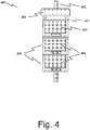
- Figure 4 illustrates a wind sensor assembly 400 that includes a sensor module 403 with power modules 405 according to one particular embodiment.
- the sensor module 403 is connected to power modules 404 to provide power to the various sensors housed and within the sensor module 403, as described above with respect to Figures 1 and 2 .
- the power modules 405 may be stacked vertically underneath the sensor module 403.
- the power modules 405 are configured to provide additional power generation capabilities as well as additional power storage capabilities.
- the power generation capabilities may be done with the use of solar cells, while the power storage capabilities may be done with the use of batteries.
- the appropriate power supply may be fed to the top sensor 401 and the bottom sensor 407 of the sensor module 403 as needed. As illustrated, the sensor module 403 remains at the top of the wind sensor assembly 400.
- the power modules 405 are stacked vertically.
- the solar cells 404 may be placed at the sides of the power modules 405. By placing the solar cells 404 at the sides of the power modules 405, this allows the power modules 405 to be stacked, thus saving space and allowing the use of more solar cells within a given area.
- FIG. 5 illustrates graphical representations that compares solar energy harvesting efficiencies of solar cell on horizontal surface and those located on vertical surfaces.
- the top graph of Figure 5 provides data points for the harvesting efficiencies of solar cells on a horizontal surface while the lower graph provides data points for the harvesting efficiencies of solar cells on a vertical surface.
- the solar efficiency level of the horizontal surface reaches a very high peak 501 at noon whereas the vertical surface reaches a much lower peak 502, and even actually experiences a small dip 503 in efficiency during the middle of the day.
- the solar cells on the vertical surface experiences a swifter rise in solar efficiency that starts earlier in the day and lasts further in the day 604 when compared to that of the horizontal surface.
- the slight dip in efficiency in the vertical surface is offset with the earlier and prolonged harvesting efficiency experienced throughout the day.
- FIG. 6 illustrates a flow chart for a method 600 using a weather sensor assembly to obtain wind measurements according to one particular embodiment.
- the method 600 includes obtaining a weather sensor assembly that includes a sensor module and a power module at step 610.
- the sensor module includes a top sensor and a bottom sensor, such that the top sensor and the bottom sensor are separated by a gap to allow air to flow through without any hindrance or obstruction.
- the power module is configured to provide power storage and power generation capabilities to the sensor module.
- method 600 at step 620 includes stacking one or more power modules vertically on top of one another underneath the sensor module.
- the power modules may have solar cells attached to the outer sides of the power module, so that the sun rays are collected at the sides of the power module. The collected solar energy may then be stored within the batteries of the power modules, so that the power is then fed to the sensor module when required and needed.
- method 600 at step 630 includes obtaining measurements from the sensor module to determine wind speed and wind direction based on the wind measurements.
- the sensor modules may include transduces that transmit and detect for pulses of sound based on the wind that passes by the ultrasonic wind sensors.
- module does not imply that the components or functionality described or claimed as part of the module are all configured in a common package. Indeed, any or all of the various components of a module, whether control logic or other components, can be combined in a single package or separately maintained and can further be distributed in multiple groupings or packages or across multiple locations.
Landscapes
- Physics & Mathematics (AREA)
- Engineering & Computer Science (AREA)
- General Physics & Mathematics (AREA)
- Environmental & Geological Engineering (AREA)
- Biodiversity & Conservation Biology (AREA)
- Atmospheric Sciences (AREA)
- Life Sciences & Earth Sciences (AREA)
- Ecology (AREA)
- Environmental Sciences (AREA)
- Acoustics & Sound (AREA)
- Multimedia (AREA)
- Aviation & Aerospace Engineering (AREA)
- Wind Motors (AREA)
- Testing Or Calibration Of Command Recording Devices (AREA)
Description
- This application claims the benefit and priority to
U.S. Provisional Patent Application Serial Number 62/299,836 filed on February 25, 2016 - The disclosed technology relates generally to ultrasonic wind sensors, otherwise known as ultrasonic anemometers. More specifically, the disclosed technology relates to the assembly ultrasonic wind sensors powered by solar cell technology.
- Ultrasonic wind sensing technology utilizes ultrasonic sound waves to measure wind velocity and wind direction. The ultrasonic wind sensors typically utilize two or more ultrasonic transducers to generate and transmit the ultrasonic signals to obtain such wind measurements. Specifically, by monitoring and obtaining the transmitted and received signals from the ultrasonic wind sensors, both wind speed and wind direction measurements may be obtained.
- While ultrasonic wind sensing technology is much more accurate than other conventional wind speed measurement devices, one of the current limitations associated with ultrasonic wind sensors is that the transmitted and received signals may be compromised by signal turbulence. This then results in faulty and incorrect measurement data. Additionally, these ultra-sonic wind sensors often require a lot of power to ensure that the specific voltage impulse is properly transmitted to the receiving end of the sensor. As such, there is a need to provide a more accurate sensing system with sufficient power generation and storage capabilities to ensure that these ultrasonic wind sensors are powered effectively and efficiently.
- A prior art example of a meteorological measurement system is disclosed in
US9075168 (B2 - A prior art example of portable surface meteorological automatic observation integrated equipment is disclosed in
CN203217092 (U ). The equipment comprises an integrated meteorological sensor, a vertical rod, an acquisition and communication box, a cabinet body, and a hand-held terminal, wherein one end of the vertical rod is connected to the cabinet body; the integrated meteorological sensor is connected to the other end of the vertical rod; and the integrated meteorological sensor is sequentially connected with the acquisition and communication box and the hand-held terminal. Meteorological information can be locally displayed through the hand-held terminal, or transmitted through a "Beidou" satellite communication mode, a CDMA mode, or a short wave communication mode to a meteorological central station so as to be displayed and stored. - A prior art example of a movable integrated ultrasonic wave weather station is disclosed in
CN204331067 (U ). The weather station comprises a pole, the top of the pole is fixed with a circular disc, the bottom of the pole is connected with three unfolding support legs which are uniformly distributed in a circle, and the bottoms of the unfolding support legs are provided with circular support sheets. The circular disc is fixed with four arc supports which are arranged in cross, and front ends of the arc supports are provided with ultrasonic wave emitters and ultrasonic receivers. The movable integrated ultrasonic wave weather station for teaching further comprises a solar cell panel, a weather information sensor seat, a protective box and a portable power supply support which are fixed to the pole in order. A data collector being connected with the ultrasonic wave emitter, the ultrasonic wave receiver and the weather information sensor seat are disposed in the protective box, and the data collector is connected with an LED display screen through a transmission module. The portable power supply support is provided with a portable power supply, and the portable power supply is connected with the data collector, the LED display and the solar cell panel. - According to various embodiments of the disclosed technology, a weather sensor assembly as defined in claim 1 is disclosed.
- Also included is a method for using a weather sensor assembly as defined in independent claim 8.
- Otherfeatures and aspects of the invention will become apparent from the following detailed description, taken in conjunction with the accompanying drawings, which illustrate, by way of example, the features in accordance with embodiments of the invention. The summary is not intended to limit the scope of the invention, which is defined solely by the claims attached hereto.
- The technology disclosed herein, in accordance with one or more various embodiments, is described in detail with reference to the following figures. The drawings are provided for purposes of illustration only and merely depict typical or example embodiments of the disclosed technology. These drawings are provided to facilitate the reader's understanding of the disclosed technology and shall not be considered limiting of the breadth, scope, or applicability thereof. It should be noted that for clarity and ease of illustration these drawings are not necessarily made to scale.
-
Figure 1 illustrates a side view of a wind sensor module with an unobstructed air gap according to one particular embodiment. -
Figure 2 illustrates a top view of a wind sensor module according to one particular embodiment. -
Figure 3 illustrates a power-optimized electronics design for each of the transducers located within a wind sensor module according to one particular embodiment. -
Figure 4 illustrates a wind sensor assembly with power modules according to one particular embodiment. -
Figure 5 illustrates graphical representations of the solar energy harvesting efficiencies of solar cells located on horizontal surfaces and those on vertical surfaces. -
Figure 6 illustrates a flow chart for using a weather sensor assembly to obtain wind measurements according to one particular embodiment. - The figures are not intended to be exhaustive or to limit the invention to the precise form disclosed. It should be understood that the invention can be practiced with modification and alteration, and that the disclosed technology be limited only by the claims and the equivalents thereof.
- The following description is not to be taken in a limiting sense, but is made merely for the purpose of describing the general principles of the disclosed embodiments. The present embodiments address the problems described in the background while also addressing other additional problems as will be seen from the following detailed description. Numerous specific details are set forth to provide a full understanding of various aspects of the subject disclosure. It will be apparent, however, to one ordinarily skilled in the art that various aspects of the subject disclosure may be practiced without some of these specific details. In other instances, well-known structures and techniques have not been shown in detail to avoid unnecessarily obscuring the subject disclosure.
-
Figure 1 illustrates a side view of awind sensor module 100 with anunobstructed air gap 102 according to one particular embodiment. As illustrated,wind sensor module 100 includes abottom sensor 101 and atop sensor 103, where agap 102 is present in between thebottom sensor 101 and thetop sensor 103. With the presence of thegap 102, wind is able to flow through so that thewind sensor module 100 is able to then detect the wind blowing through and determine the appropriate wind measurements, such as wind speed and wind direction. Additionally, thegap 102 is constructed such that the space is devoid of any objects or devices, further ensuring that there will be no signal interference when determining the appropriate wind measurements. - More specifically, the
wind sensor module 100 may include a plurality of ultrasonic transducers spaced equally around the surface of thebottom sensor 101. But to ensure that thegap 102 area is unobstructed by any devices or objects, the transducers may lay flat on the surface of thebottom sensor 101. By way of example only, a range from two to six ultrasonic transducers may be equally spaced around the top most surface of thebottom sensor 101. In such an embodiment, each of the transducers may take turns transmitting a signal, in which the remaining transducers may receive and detect the transmitted pulse. In some instances, select transducers may be assigned to only transmit pulsed signals while the remaining others may be assigned to only detect the transmitted pulsed signals. In other instances, each of the transducers may take turns transmitting and receiving pulsed signals. - Located above the
bottom sensor 101 and thegap 102 area is thetop sensor 103. Thetop sensor 103 may include other various sensors or devices that are not transducers. For example, such other sensors may be those that provide measurements for air temperature, barometric pressure, humidity, and the like. - Additionally, in further embodiments, the
top surface 105 of thetop wind 103 may be configured so that the area is devoid of any sensors to reserve the area for devices that need to be exposed to the environment, such as awireless transmission antenna 104 by way of example only. However, it should be noted that other equipment or hardware can be included on thetop surface 105, such as a camera, GPS, etc. -
Figure 2 illustrates a top view of the arrangement of thewind sensor system 200. As illustrated, thewind sensor system 200 includes four individualultrasonic wind sensors 201 A, B, C, D. Here, there are a plurality ofultrasonic wind sensors 201 A, B, C, D that are equally spaced apart from one another so that they essentially form a ring around thecenter 202. As illustrated inFigure 1 with the gap area, thecenter 202 area here is where the gap area is located. As depicted inFigure 2 , thecenter 202 area is clear of any obstructions so that air may pass through without any interference. - Each of the
ultrasonic wind sensors 201 A, B, C, D may include transmitters so that pulses of sound may be transmitted and detected. In this particular embodiment, the 4ultrasonic wind sensors 201 A, B, C, D may work in pairs. Thus, with each pair, one of theultrasonic wind sensor 201 C,D immediately opposite detects the transmitted pulse, and vice versa. The time from which it takes for the signal to be transmitted and detected is then measured through the use of an electronic timer. The time may be logged to determine the average speed of sound, which in turn can be used to estimate air temperature. The overall wind vector may also be determined by using the wind speed along thefirst axis 203 and thesecond axis 204 as the two vector components. - While this particular example provides 4
ultrasonic wind sensors 201 A, B, C, D by way of example only, it should be noted that various different number of wind sensors may be utilized. For example, a range of two to six individual ultrasonic wind sensors may be used. -
Figure 3 illustrates a power-optimizedelectronics design 300 for the individual ultrasonic wind sensors according to one particular embodiment. Because the wind sensor system may often consume a lot of electrical power in order to operate and provide the necessary wind measurements, an efficient and optimal power management source is needed. Here, as illustrated, this power-optimizedelectronics design 300 utilizes a topology that allows itself to completely avoid the power-intensive generation of the necessary voltage supply to operate the wind sensor system. While this particular example utilizes a 400V supply requirement, it should be noted that any voltage supply requirement needed to power on the wind sensor system may be utilized with this power-optimizedelectronics design 300. - Here, the power-optimized
electronics design 300 uses adrive signal 301 that is used to control the high-voltage MOSFET transistor 302. The high-voltage MOSFET transistor 303 may be connected to themain power supply 303 through a fly-back inductor 304. While the drive signal is logic-high, the transistor is turned on to then cause the current to build in the inductor until the drive signal is turned off. This may cause the inductor voltage to increase rapidly as a result of the rapid drop in current. The voltage in the inductor may then reach 400V momentarily (e.g., 100 nS duration), which then drives the ultrasonic transducer 305 through a pair ofdiodes 306 that act as an incremental short-circuit for large signals, but then effectively disconnects the transducer after the pulse is over. - A separate circuit may immediately be triggered after the pulse is over by using an
inverting topology 307 to drive a separate high-voltage transistor 308 and short the driven side of the sonic transducer when the transducer is not driven. The non-driven side of the sonic transducer may be grounded through twodiodes 309 that act an incremental open circuit for large signals, but which also acts as an incremental short circuit for the very small signal that is induced in the transducer during receive mode. In this particular case, the large signals may be characterized as those where the drive signal is 400V, and a very small signal as one that is in the microvolt range, by way of example only. This circuit then allows each transducer to be driven with a 400V impulse during transmit mode while allowing for detection of a few micro-volts during receive or detection mode. As a result, this particular embodiment allows for the ability to generate 400V impulse signal while drawing only 50 microamps for all of the transducers used in the sensor module. - This power optimized
electronics design 300 may be implemented into each transducer of the sensor module. However, it should be noted that this power optimizedelectronics design 300 may be implemented into however many transducers that are available. Thus, sensor module with 2 transducers will have this disclosed power optimized electronics design for those 2 transducers. -
Figure 4 illustrates awind sensor assembly 400 that includes asensor module 403 withpower modules 405 according to one particular embodiment. Here, thesensor module 403 is connected topower modules 404 to provide power to the various sensors housed and within thesensor module 403, as described above with respect toFigures 1 and2 . - In some embodiments, the
power modules 405 may be stacked vertically underneath thesensor module 403. Thepower modules 405 are configured to provide additional power generation capabilities as well as additional power storage capabilities. By way of example only, the power generation capabilities may be done with the use of solar cells, while the power storage capabilities may be done with the use of batteries. By stacking and incorporating thepower modules 405 to be in connection with thesensor module 403, the appropriate power supply may be fed to thetop sensor 401 and thebottom sensor 407 of thesensor module 403 as needed. As illustrated, thesensor module 403 remains at the top of thewind sensor assembly 400. - In further embodiments, the
power modules 405 are stacked vertically. By way of example only, thesolar cells 404 may be placed at the sides of thepower modules 405. By placing thesolar cells 404 at the sides of thepower modules 405, this allows thepower modules 405 to be stacked, thus saving space and allowing the use of more solar cells within a given area. - While it may seem that the
solar cells 404 will not receive a sufficient amount of sunlight if they are to be located at the sides of the power module, this is not the case. Indeed, this unexpected result is evidenced after studying and observing the path of the sun across the sky at different latitudes. Indeed, our calculations show that the total accumulated solar exposure is higher when thesolar cells 404 are positioned at the sides in a vertical manner when compared to those placed in a horizontal manner, as detailed further below. - More specifically, we observed the the sun's angles throughout the day and then applied a cosine calculation to these angles relative to a normal vector from a solar-energy collecting surface, such as solar cells that are vertically stacked as described in
Figure 4 . The application of the cosine was then used to calculate solar energy harvesting efficiency. To compare the difference in energy harvesting efficiency,Figure 5 illustrates graphical representations that compares solar energy harvesting efficiencies of solar cell on horizontal surface and those located on vertical surfaces. - Here, the top graph of
Figure 5 provides data points for the harvesting efficiencies of solar cells on a horizontal surface while the lower graph provides data points for the harvesting efficiencies of solar cells on a vertical surface. As depicted, at a latitude of 25 degrees North, the solar efficiency level of the horizontal surface reaches a veryhigh peak 501 at noon whereas the vertical surface reaches a muchlower peak 502, and even actually experiences asmall dip 503 in efficiency during the middle of the day. However, it is clear that the solar cells on the vertical surface experiences a swifter rise in solar efficiency that starts earlier in the day and lasts further in the day 604 when compared to that of the horizontal surface. As a result, the slight dip in efficiency in the vertical surface is offset with the earlier and prolonged harvesting efficiency experienced throughout the day. - As further illustrated in
Figure 5 , at a latitude of 60 degrees, the harvesting efficiency of the horizontal surface peaks 504 at no more than 8% while the vertical surface reaches a peak harvesting efficiency of approximately 25%. These graphical comparisons atFigure 5 show how much more effective vertical surfaces can be at collecting sun energy when compared to horizontal surfaces. Thus, the placement of solar cells on the vertical surface may be much more effective at collecting sun energy than if they were placed on a horizontal surface. -
Figure 6 illustrates a flow chart for amethod 600 using a weather sensor assembly to obtain wind measurements according to one particular embodiment. Themethod 600 includes obtaining a weather sensor assembly that includes a sensor module and a power module atstep 610. The sensor module includes a top sensor and a bottom sensor, such that the top sensor and the bottom sensor are separated by a gap to allow air to flow through without any hindrance or obstruction. Additionally, the power module is configured to provide power storage and power generation capabilities to the sensor module. - Next,
method 600 atstep 620 includes stacking one or more power modules vertically on top of one another underneath the sensor module. In some instances, the power modules may have solar cells attached to the outer sides of the power module, so that the sun rays are collected at the sides of the power module. The collected solar energy may then be stored within the batteries of the power modules, so that the power is then fed to the sensor module when required and needed. - Next,
method 600 atstep 630 includes obtaining measurements from the sensor module to determine wind speed and wind direction based on the wind measurements. As explained above, the sensor modules may include transduces that transmit and detect for pulses of sound based on the wind that passes by the ultrasonic wind sensors. - Terms and phrases used in this document, and variations thereof, unless otherwise expressly stated, should be construed as open ended as opposed to limiting. As examples of the foregoing: the term "including" should be read as meaning "including, without limitation" or the like; the term "example" is used to provide exemplary instances of the item in discussion, not an exhaustive or limiting list thereof; the terms "a" or "an" should be read as meaning "at least one," "one or more" or the like; and adjectives such as "conventional," "traditional," "normal," "standard," "known" and terms of similar meaning should not be construed as limiting the item described to a given time period or to an item available as of a given time, but instead should be read to encompass conventional, traditional, normal, or standard technologies that may be available or known now or at any time in the future. Likewise, where this document refers to technologies that would be apparent or known to one of ordinary skill in the art, such technologies encompass those apparent or known to the skilled artisan now or at any time in the future.
- The presence of broadening words and phrases such as "one or more," "at least," "but not limited to" or other like phrases in some instances shall not be read to mean that the narrower case is intended or required in instances where such broadening phrases may be absent. The use of the term "module" does not imply that the components or functionality described or claimed as part of the module are all configured in a common package. Indeed, any or all of the various components of a module, whether control logic or other components, can be combined in a single package or separately maintained and can further be distributed in multiple groupings or packages or across multiple locations.
Claims (13)
- A weather sensor assembly (400) comprising:a sensor module (100, 403) comprising:a top sensor (103, 401); anda bottom sensor (101, 407), wherein the top sensor (103, 401) and the bottom sensor (101, 407) are separated by a gap (102) to allow air to flow in between the top sensor (103, 401) and the bottom sensor (101, 407) unobstructed, wherein the bottom sensor (101, 407) comprises a plurality of ultrasonic transducers to measure the air flowing through the gap (102) between the bottom sensor (101, 407) and the top sensor (103, 401) to determine at least one of wind speed and wind direction;the weather sensor assembly being characterised in that it comprises two or more power modules (405) with power storage and power generation capabilities placed beneath the sensor module (100, 403), wherein the power modules (405) are stacked vertically on top of one another so as to be in connection with the sensor module (100, 403), the power modules being configured to provide power to the sensor module (100, 403), wherein each of the two or more power modules (405) comprises a solar cell attached to a side of the respective one of the two or more power modules.
- The weather sensor of claim 1, wherein the two or more power modules (405) that are stacked vertically allow the two or more power modules (405) to establish a linked connection with each other to power the sensor module (100, 403).
- The weather sensor assembly of claim 1, wherein;(i) the plurality of ultrasonic transducers of the bottom sensor (101, 407) comprises four transducers to measure the air flowing through the gap (102) between the bottom sensor (101, 407) and the top sensor (103, 401) to determine at least one of wind speed and wind direction, and/or(ii) wherein the plurality of ultrasonic transducers of the bottom sensor (101, 407) comprises a first transducer that transmits a pulse of sound to a second transducer opposite from the first transducer, such that the second transducer detects the pulse of sound.
- The weather sensor assembly of claim 3, part (ii), wherein the plurality of ultrasonic transducers of the bottom sensor (101, 407) comprises a third transducer that transmits the pulse of sound to a fourth transducer opposite from the first transducer, such that the fourth transducer detects the pulse of sound.
- The weather sensor assembly of claim 1, wherein the plurality of ultrasonic transducers of the bottom sensor (101, 407) comprises six transducers.
- The weather sensor assembly of claim 1, wherein the top sensor (103, 401) comprises a transmission antenna (104) placed on a first surface (105) of the top sensor (103, 401).
- The weather sensor assembly of claim 1, wherein the top sensor (103, 401) comprises sensors or instruments to obtain measurements of at least one of air temperature, barometric pressure, location, and humidity.
- A method for using a weather sensor assembly (400) comprising:obtaining a weather sensor assembly comprising:a sensor module (100, 403) comprising:a top sensor (103, 401); anda bottom sensor (101, 407), wherein the top sensor (103, 401) and the bottom sensor (101, 407) are separated by a gap (102)to allow air to flow in between the top sensor (103, 401) and the bottom sensor (101, 407) unobstructed, wherein the bottom sensor (101, 407) comprises a plurality of ultrasonic transducers to measure the air flowing through the gap (102) between the bottom sensor (101, 407) and the top sensor (103, 401) to determine at least one of wind speed and wind direction; andtwo or more power modules (405) with power storage and power generation capabilities;stacking the power modules (405) vertically on top of one another so as to be in connection with the sensor module (100, 403), the power modules being configured to provide power to the sensor module (100, 403), wherein each of the two or more power modules (405) comprises a solar cell attached to a side of the respective one of the two or more power modules; andobtaining measurements from the sensor module (100, 403) to determine at least wind speed and wind direction.
- The method for using the wind sensor assembly (400) of claim 8, wherein the solar cells (404) provide additional power generation capabilities to the weather sensor (400).
- The method of using a wind sensor (400) assembly of claim 8, wherein;(i) the plurality of ultrasonic transducers of the bottom sensor (101, 407) comprises four transducers to measure air flowing through the gap (102) between the bottom sensor (101, 407) and the top sensor (103, 401), and optionally or preferably,(ii) further comprising transmitting pulses of sound from a first transducer to a second transducer located opposite from the first transducer.
- The method of using a wind sensor assembly (400) of claim 10, part (ii) further comprising transmitting pulses of sound from a third transducer to a fourth transducer located opposite from the third transducer, and optionally or preferably, further comprising having the second transducer and the fourth transducer detect the pulses of sound from the first transducer and the third transducer respectively.
- The method of using a wind sensor assembly (400) of claim 8, further comprising utilizing three transducers to measure the air flowing through the gap between the second sensor (101, 407) and the first sensor (103, 401); or
wherein the plurality of ultrasonic transducers comprises six ultrasonic transducers. - The method of using a wind sensor assembly (400) of claim 8, further comprising placing a transmission antenna (104) on a first surface of the top sensor (103, 401); or
the method of using a wind sensor assembly (400) of claim 8, wherein the top sensor (103, 401) comprises sensors or instruments to obtain measurements of at least one of air temperature, barometric pressure, location, and humidity.
Applications Claiming Priority (2)
| Application Number | Priority Date | Filing Date | Title |
|---|---|---|---|
| US201662299836P | 2016-02-25 | 2016-02-25 | |
| PCT/US2017/017536 WO2017146920A1 (en) | 2016-02-25 | 2017-02-10 | Power-oriented weather sensor |
Publications (2)
| Publication Number | Publication Date |
|---|---|
| EP3420383A1 EP3420383A1 (en) | 2019-01-02 |
| EP3420383B1 true EP3420383B1 (en) | 2021-04-07 |
Family
ID=58159525
Family Applications (1)
| Application Number | Title | Priority Date | Filing Date |
|---|---|---|---|
| EP17707151.1A Active EP3420383B1 (en) | 2016-02-25 | 2017-02-10 | Power-oriented weather sensor |
Country Status (5)
| Country | Link |
|---|---|
| US (1) | US10429546B1 (en) |
| EP (1) | EP3420383B1 (en) |
| AU (1) | AU2017223177B2 (en) |
| CA (1) | CA3013934C (en) |
| WO (1) | WO2017146920A1 (en) |
Families Citing this family (19)
| Publication number | Priority date | Publication date | Assignee | Title |
|---|---|---|---|---|
| JP7140351B2 (en) * | 2018-06-11 | 2022-09-21 | ミネベアミツミ株式会社 | sensor unit |
| US12399164B2 (en) | 2018-06-19 | 2025-08-26 | Seekops Inc. | Emissions estimate model algorithms and methods |
| EP3811171B1 (en) | 2018-06-19 | 2025-02-26 | SeekOps Inc. | Emissions estimate model algorithms and methods |
| WO2019246283A1 (en) | 2018-06-19 | 2019-12-26 | Seekops Inc. | Localization analytics algorithms and methods |
| US12044666B2 (en) | 2018-07-30 | 2024-07-23 | Seekops Inc. | Ultra-lightweight, handheld gas leak detection device |
| WO2020086499A1 (en) | 2018-10-22 | 2020-04-30 | Seekops Inc. | A uav-borne, high-bandwidth, lightweight point sensor for quantifying greenhouse gases in atmospheric strata |
| EP3948202A4 (en) | 2019-04-05 | 2023-01-04 | SeekOps Inc. | TIME AND DATA EFFICIENT LEAK DETECTION ASSURANCE |
| US11994464B2 (en) | 2019-04-05 | 2024-05-28 | Seekops Inc. | Analog signal processing for a lightweight and compact laser-based trace gas sensor |
| EP4010246A4 (en) | 2019-08-05 | 2023-09-13 | SeekOps Inc. | Rapidly deployable uas system for autonomous inspection operations using a combined payload |
| WO2021055902A1 (en) | 2019-09-20 | 2021-03-25 | Seekops Inc. | Spectral fitting of compact laser-based trace gas sensor measurements for high dynamic range (hdr) |
| WO2021067844A1 (en) | 2019-10-04 | 2021-04-08 | Seekops Inc. | Closed surface flight pattern generation for unmanned aerial vehicle (uav) flux plane assessment |
| US11614430B2 (en) * | 2019-12-19 | 2023-03-28 | Seekops Inc. | Concurrent in-situ measurement of wind speed and trace gases on mobile platforms for localization and qualification of emissions |
| US11988598B2 (en) | 2019-12-31 | 2024-05-21 | Seekops Inc. | Optical cell cleaner |
| EP4100719A4 (en) | 2020-02-05 | 2024-02-21 | SeekOps Inc. | Multiple path length optical cell for trace gas measurement |
| US12055485B2 (en) | 2020-02-05 | 2024-08-06 | Seekops Inc. | Multispecies measurement platform using absorption spectroscopy for measurement of co-emitted trace gases |
| WO2021195394A1 (en) | 2020-03-25 | 2021-09-30 | Seekops Inc. | Logarithmic demodulator for laser wavelength-modulaton spectroscopy |
| US11748866B2 (en) | 2020-07-17 | 2023-09-05 | Seekops Inc. | Systems and methods of automated detection of gas plumes using optical imaging |
| WO2022016107A1 (en) | 2020-07-17 | 2022-01-20 | Seekops Inc. | Uas work practice |
| WO2022093864A1 (en) | 2020-10-27 | 2022-05-05 | Seekops Inc. | Methods and apparatus for measuring methane emissions with an optical open-cavity methane sensor |
Family Cites Families (6)
| Publication number | Priority date | Publication date | Assignee | Title |
|---|---|---|---|---|
| FR2800876B1 (en) | 1999-11-04 | 2002-01-18 | Lcj Capteurs | IMPROVEMENT WITH ULTRASONIC ANEMOMETERS |
| US7870784B2 (en) * | 2009-06-23 | 2011-01-18 | General Electric Company | Method and apparatus for measuring wind velocity |
| DE102010060663B4 (en) * | 2010-11-18 | 2018-03-08 | Ssb Wind Systems Gmbh & Co. Kg | Meteorological measuring arrangement |
| CN203217092U (en) | 2013-04-08 | 2013-09-25 | 中国人民解放军理工大学 | Portable surface meteorological automatic observation integrated equipment |
| CN204331067U (en) | 2014-12-30 | 2015-05-13 | 南京信息工程大学 | Teaching mobile integrated ultrasound wave weather station |
| CN204855549U (en) | 2015-07-10 | 2015-12-09 | 黑龙江省森林工程与环境研究所 | Forest ecosystem apoplexy factor monitoring devices |
-
2016
- 2016-12-23 US US15/390,196 patent/US10429546B1/en active Active
-
2017
- 2017-02-10 EP EP17707151.1A patent/EP3420383B1/en active Active
- 2017-02-10 CA CA3013934A patent/CA3013934C/en active Active
- 2017-02-10 AU AU2017223177A patent/AU2017223177B2/en active Active
- 2017-02-10 WO PCT/US2017/017536 patent/WO2017146920A1/en not_active Ceased
Non-Patent Citations (1)
| Title |
|---|
| None * |
Also Published As
| Publication number | Publication date |
|---|---|
| US10429546B1 (en) | 2019-10-01 |
| AU2017223177A1 (en) | 2018-08-16 |
| AU2017223177B2 (en) | 2020-08-13 |
| EP3420383A1 (en) | 2019-01-02 |
| CA3013934C (en) | 2023-01-31 |
| WO2017146920A1 (en) | 2017-08-31 |
| CA3013934A1 (en) | 2017-08-31 |
Similar Documents
| Publication | Publication Date | Title |
|---|---|---|
| US10429546B1 (en) | Weather sensor including vertically stacked multi-power modules | |
| US20110220182A1 (en) | Solar Panel Tracking and Performance Monitoring Through Wireless Communication | |
| US8592738B1 (en) | Alignment device for use with a solar tracking photovoltaic array | |
| CN109334867B (en) | Omnidirectional stable buoy for data calibration of sea-air interface observation wave glider | |
| CN103728463A (en) | Ultrasonic wind meter and measuring method | |
| JP2010016331A (en) | Solar tracking device and tracking method thereof | |
| US11674944B2 (en) | In-ground wireless soil moisture sensor | |
| CN109080831B (en) | Conical intelligent soil detection device based on unmanned aerial vehicle | |
| CN103616078B (en) | The calibration of a kind of thermal infrared load Portable field and water surface temperature verification system device | |
| JP6893678B2 (en) | Wind measuring device | |
| KR102101065B1 (en) | Adaptive environmental integrated measuring system in the polar regions | |
| KR101045240B1 (en) | Apparatus and method for measuring cross-sectional data for rainfall and snowfall calculation using 3D wireless weather forecast module | |
| CN215727476U (en) | Real-time detection device for soil moisture content | |
| CN109407079A (en) | A kind of regional positioning device and method based on attitude transducer calibration | |
| CN106018877A (en) | Ultrasonic two-dimensional wind direction and wind speed sensor | |
| CN212872888U (en) | Communication beacon | |
| CN210243837U (en) | Sludge deposition on-line monitoring system | |
| CN210108476U (en) | Tidal level monitoring device and system | |
| CN203217092U (en) | Portable surface meteorological automatic observation integrated equipment | |
| CN106954621A (en) | A kind of supersonic wave bird driving device detector and detection method | |
| CN209373154U (en) | A kind of integrated form meteorology detector | |
| CN206945685U (en) | A kind of oxygen in soil continuous monitoring device | |
| CN223253215U (en) | A test buoy | |
| JP6059557B2 (en) | Radiation measurement system | |
| CN213302505U (en) | Active target for L-band radar detection |
Legal Events
| Date | Code | Title | Description |
|---|---|---|---|
| STAA | Information on the status of an ep patent application or granted ep patent |
Free format text: STATUS: UNKNOWN |
|
| STAA | Information on the status of an ep patent application or granted ep patent |
Free format text: STATUS: THE INTERNATIONAL PUBLICATION HAS BEEN MADE |
|
| PUAI | Public reference made under article 153(3) epc to a published international application that has entered the european phase |
Free format text: ORIGINAL CODE: 0009012 |
|
| STAA | Information on the status of an ep patent application or granted ep patent |
Free format text: STATUS: REQUEST FOR EXAMINATION WAS MADE |
|
| 17P | Request for examination filed |
Effective date: 20180801 |
|
| AK | Designated contracting states |
Kind code of ref document: A1 Designated state(s): AL AT BE BG CH CY CZ DE DK EE ES FI FR GB GR HR HU IE IS IT LI LT LU LV MC MK MT NL NO PL PT RO RS SE SI SK SM TR |
|
| AX | Request for extension of the european patent |
Extension state: BA ME |
|
| DAV | Request for validation of the european patent (deleted) | ||
| DAX | Request for extension of the european patent (deleted) | ||
| RAP1 | Party data changed (applicant data changed or rights of an application transferred) |
Owner name: INTELLISENSE SYSTEMS, INC. |
|
| STAA | Information on the status of an ep patent application or granted ep patent |
Free format text: STATUS: EXAMINATION IS IN PROGRESS |
|
| 17Q | First examination report despatched |
Effective date: 20200319 |
|
| GRAP | Despatch of communication of intention to grant a patent |
Free format text: ORIGINAL CODE: EPIDOSNIGR1 |
|
| STAA | Information on the status of an ep patent application or granted ep patent |
Free format text: STATUS: GRANT OF PATENT IS INTENDED |
|
| INTG | Intention to grant announced |
Effective date: 20201124 |
|
| GRAS | Grant fee paid |
Free format text: ORIGINAL CODE: EPIDOSNIGR3 |
|
| GRAA | (expected) grant |
Free format text: ORIGINAL CODE: 0009210 |
|
| STAA | Information on the status of an ep patent application or granted ep patent |
Free format text: STATUS: THE PATENT HAS BEEN GRANTED |
|
| AK | Designated contracting states |
Kind code of ref document: B1 Designated state(s): AL AT BE BG CH CY CZ DE DK EE ES FI FR GB GR HR HU IE IS IT LI LT LU LV MC MK MT NL NO PL PT RO RS SE SI SK SM TR |
|
| REG | Reference to a national code |
Ref country code: GB Ref legal event code: FG4D |
|
| REG | Reference to a national code |
Ref country code: AT Ref legal event code: REF Ref document number: 1380420 Country of ref document: AT Kind code of ref document: T Effective date: 20210415 Ref country code: CH Ref legal event code: EP |
|
| REG | Reference to a national code |
Ref country code: DE Ref legal event code: R096 Ref document number: 602017036122 Country of ref document: DE |
|
| REG | Reference to a national code |
Ref country code: IE Ref legal event code: FG4D |
|
| REG | Reference to a national code |
Ref country code: DE Ref legal event code: R082 Ref document number: 602017036122 Country of ref document: DE Representative=s name: KROHER STROBEL RECHTS- UND PATENTANWAELTE PART, DE |
|
| REG | Reference to a national code |
Ref country code: LT Ref legal event code: MG9D |
|
| REG | Reference to a national code |
Ref country code: NL Ref legal event code: MP Effective date: 20210407 Ref country code: AT Ref legal event code: MK05 Ref document number: 1380420 Country of ref document: AT Kind code of ref document: T Effective date: 20210407 |
|
| PG25 | Lapsed in a contracting state [announced via postgrant information from national office to epo] |
Ref country code: BG Free format text: LAPSE BECAUSE OF FAILURE TO SUBMIT A TRANSLATION OF THE DESCRIPTION OR TO PAY THE FEE WITHIN THE PRESCRIBED TIME-LIMIT Effective date: 20210707 Ref country code: AT Free format text: LAPSE BECAUSE OF FAILURE TO SUBMIT A TRANSLATION OF THE DESCRIPTION OR TO PAY THE FEE WITHIN THE PRESCRIBED TIME-LIMIT Effective date: 20210407 Ref country code: HR Free format text: LAPSE BECAUSE OF FAILURE TO SUBMIT A TRANSLATION OF THE DESCRIPTION OR TO PAY THE FEE WITHIN THE PRESCRIBED TIME-LIMIT Effective date: 20210407 Ref country code: NL Free format text: LAPSE BECAUSE OF FAILURE TO SUBMIT A TRANSLATION OF THE DESCRIPTION OR TO PAY THE FEE WITHIN THE PRESCRIBED TIME-LIMIT Effective date: 20210407 Ref country code: LT Free format text: LAPSE BECAUSE OF FAILURE TO SUBMIT A TRANSLATION OF THE DESCRIPTION OR TO PAY THE FEE WITHIN THE PRESCRIBED TIME-LIMIT Effective date: 20210407 Ref country code: FI Free format text: LAPSE BECAUSE OF FAILURE TO SUBMIT A TRANSLATION OF THE DESCRIPTION OR TO PAY THE FEE WITHIN THE PRESCRIBED TIME-LIMIT Effective date: 20210407 |
|
| PG25 | Lapsed in a contracting state [announced via postgrant information from national office to epo] |
Ref country code: NO Free format text: LAPSE BECAUSE OF FAILURE TO SUBMIT A TRANSLATION OF THE DESCRIPTION OR TO PAY THE FEE WITHIN THE PRESCRIBED TIME-LIMIT Effective date: 20210707 Ref country code: PT Free format text: LAPSE BECAUSE OF FAILURE TO SUBMIT A TRANSLATION OF THE DESCRIPTION OR TO PAY THE FEE WITHIN THE PRESCRIBED TIME-LIMIT Effective date: 20210809 Ref country code: PL Free format text: LAPSE BECAUSE OF FAILURE TO SUBMIT A TRANSLATION OF THE DESCRIPTION OR TO PAY THE FEE WITHIN THE PRESCRIBED TIME-LIMIT Effective date: 20210407 Ref country code: RS Free format text: LAPSE BECAUSE OF FAILURE TO SUBMIT A TRANSLATION OF THE DESCRIPTION OR TO PAY THE FEE WITHIN THE PRESCRIBED TIME-LIMIT Effective date: 20210407 Ref country code: SE Free format text: LAPSE BECAUSE OF FAILURE TO SUBMIT A TRANSLATION OF THE DESCRIPTION OR TO PAY THE FEE WITHIN THE PRESCRIBED TIME-LIMIT Effective date: 20210407 Ref country code: GR Free format text: LAPSE BECAUSE OF FAILURE TO SUBMIT A TRANSLATION OF THE DESCRIPTION OR TO PAY THE FEE WITHIN THE PRESCRIBED TIME-LIMIT Effective date: 20210708 Ref country code: LV Free format text: LAPSE BECAUSE OF FAILURE TO SUBMIT A TRANSLATION OF THE DESCRIPTION OR TO PAY THE FEE WITHIN THE PRESCRIBED TIME-LIMIT Effective date: 20210407 Ref country code: IS Free format text: LAPSE BECAUSE OF FAILURE TO SUBMIT A TRANSLATION OF THE DESCRIPTION OR TO PAY THE FEE WITHIN THE PRESCRIBED TIME-LIMIT Effective date: 20210807 |
|
| REG | Reference to a national code |
Ref country code: DE Ref legal event code: R097 Ref document number: 602017036122 Country of ref document: DE |
|
| PG25 | Lapsed in a contracting state [announced via postgrant information from national office to epo] |
Ref country code: CZ Free format text: LAPSE BECAUSE OF FAILURE TO SUBMIT A TRANSLATION OF THE DESCRIPTION OR TO PAY THE FEE WITHIN THE PRESCRIBED TIME-LIMIT Effective date: 20210407 Ref country code: DK Free format text: LAPSE BECAUSE OF FAILURE TO SUBMIT A TRANSLATION OF THE DESCRIPTION OR TO PAY THE FEE WITHIN THE PRESCRIBED TIME-LIMIT Effective date: 20210407 Ref country code: EE Free format text: LAPSE BECAUSE OF FAILURE TO SUBMIT A TRANSLATION OF THE DESCRIPTION OR TO PAY THE FEE WITHIN THE PRESCRIBED TIME-LIMIT Effective date: 20210407 Ref country code: ES Free format text: LAPSE BECAUSE OF FAILURE TO SUBMIT A TRANSLATION OF THE DESCRIPTION OR TO PAY THE FEE WITHIN THE PRESCRIBED TIME-LIMIT Effective date: 20210407 Ref country code: RO Free format text: LAPSE BECAUSE OF FAILURE TO SUBMIT A TRANSLATION OF THE DESCRIPTION OR TO PAY THE FEE WITHIN THE PRESCRIBED TIME-LIMIT Effective date: 20210407 Ref country code: SM Free format text: LAPSE BECAUSE OF FAILURE TO SUBMIT A TRANSLATION OF THE DESCRIPTION OR TO PAY THE FEE WITHIN THE PRESCRIBED TIME-LIMIT Effective date: 20210407 Ref country code: SK Free format text: LAPSE BECAUSE OF FAILURE TO SUBMIT A TRANSLATION OF THE DESCRIPTION OR TO PAY THE FEE WITHIN THE PRESCRIBED TIME-LIMIT Effective date: 20210407 |
|
| PLBE | No opposition filed within time limit |
Free format text: ORIGINAL CODE: 0009261 |
|
| STAA | Information on the status of an ep patent application or granted ep patent |
Free format text: STATUS: NO OPPOSITION FILED WITHIN TIME LIMIT |
|
| 26N | No opposition filed |
Effective date: 20220110 |
|
| PG25 | Lapsed in a contracting state [announced via postgrant information from national office to epo] |
Ref country code: IS Free format text: LAPSE BECAUSE OF FAILURE TO SUBMIT A TRANSLATION OF THE DESCRIPTION OR TO PAY THE FEE WITHIN THE PRESCRIBED TIME-LIMIT Effective date: 20210807 Ref country code: AL Free format text: LAPSE BECAUSE OF FAILURE TO SUBMIT A TRANSLATION OF THE DESCRIPTION OR TO PAY THE FEE WITHIN THE PRESCRIBED TIME-LIMIT Effective date: 20210407 |
|
| PG25 | Lapsed in a contracting state [announced via postgrant information from national office to epo] |
Ref country code: IT Free format text: LAPSE BECAUSE OF FAILURE TO SUBMIT A TRANSLATION OF THE DESCRIPTION OR TO PAY THE FEE WITHIN THE PRESCRIBED TIME-LIMIT Effective date: 20210407 |
|
| PG25 | Lapsed in a contracting state [announced via postgrant information from national office to epo] |
Ref country code: MC Free format text: LAPSE BECAUSE OF FAILURE TO SUBMIT A TRANSLATION OF THE DESCRIPTION OR TO PAY THE FEE WITHIN THE PRESCRIBED TIME-LIMIT Effective date: 20210407 |
|
| REG | Reference to a national code |
Ref country code: CH Ref legal event code: PL |
|
| REG | Reference to a national code |
Ref country code: BE Ref legal event code: MM Effective date: 20220228 |
|
| PG25 | Lapsed in a contracting state [announced via postgrant information from national office to epo] |
Ref country code: LU Free format text: LAPSE BECAUSE OF NON-PAYMENT OF DUE FEES Effective date: 20220210 |
|
| PG25 | Lapsed in a contracting state [announced via postgrant information from national office to epo] |
Ref country code: LI Free format text: LAPSE BECAUSE OF NON-PAYMENT OF DUE FEES Effective date: 20220228 Ref country code: IE Free format text: LAPSE BECAUSE OF NON-PAYMENT OF DUE FEES Effective date: 20220210 Ref country code: CH Free format text: LAPSE BECAUSE OF NON-PAYMENT OF DUE FEES Effective date: 20220228 |
|
| PG25 | Lapsed in a contracting state [announced via postgrant information from national office to epo] |
Ref country code: BE Free format text: LAPSE BECAUSE OF NON-PAYMENT OF DUE FEES Effective date: 20220228 |
|
| PG25 | Lapsed in a contracting state [announced via postgrant information from national office to epo] |
Ref country code: HU Free format text: LAPSE BECAUSE OF FAILURE TO SUBMIT A TRANSLATION OF THE DESCRIPTION OR TO PAY THE FEE WITHIN THE PRESCRIBED TIME-LIMIT; INVALID AB INITIO Effective date: 20170210 |
|
| PG25 | Lapsed in a contracting state [announced via postgrant information from national office to epo] |
Ref country code: MK Free format text: LAPSE BECAUSE OF FAILURE TO SUBMIT A TRANSLATION OF THE DESCRIPTION OR TO PAY THE FEE WITHIN THE PRESCRIBED TIME-LIMIT Effective date: 20210407 Ref country code: CY Free format text: LAPSE BECAUSE OF FAILURE TO SUBMIT A TRANSLATION OF THE DESCRIPTION OR TO PAY THE FEE WITHIN THE PRESCRIBED TIME-LIMIT Effective date: 20210407 |
|
| PG25 | Lapsed in a contracting state [announced via postgrant information from national office to epo] |
Ref country code: MT Free format text: LAPSE BECAUSE OF FAILURE TO SUBMIT A TRANSLATION OF THE DESCRIPTION OR TO PAY THE FEE WITHIN THE PRESCRIBED TIME-LIMIT Effective date: 20210407 |
|
| PG25 | Lapsed in a contracting state [announced via postgrant information from national office to epo] |
Ref country code: TR Free format text: LAPSE BECAUSE OF FAILURE TO SUBMIT A TRANSLATION OF THE DESCRIPTION OR TO PAY THE FEE WITHIN THE PRESCRIBED TIME-LIMIT Effective date: 20210407 |
|
| PGFP | Annual fee paid to national office [announced via postgrant information from national office to epo] |
Ref country code: GB Payment date: 20251218 Year of fee payment: 10 |
|
| PGFP | Annual fee paid to national office [announced via postgrant information from national office to epo] |
Ref country code: FR Payment date: 20251128 Year of fee payment: 10 |
|
| PGFP | Annual fee paid to national office [announced via postgrant information from national office to epo] |
Ref country code: DE Payment date: 20251216 Year of fee payment: 10 |