EP3420196B1 - Turbinenschaufel mit kühlstruktur und zugehöriges herstellungsverfahren - Google Patents
Turbinenschaufel mit kühlstruktur und zugehöriges herstellungsverfahren Download PDFInfo
- Publication number
- EP3420196B1 EP3420196B1 EP17714666.9A EP17714666A EP3420196B1 EP 3420196 B1 EP3420196 B1 EP 3420196B1 EP 17714666 A EP17714666 A EP 17714666A EP 3420196 B1 EP3420196 B1 EP 3420196B1
- Authority
- EP
- European Patent Office
- Prior art keywords
- turbine blade
- cooling
- blade
- cooling structure
- turbine
- Prior art date
- Legal status (The legal status is an assumption and is not a legal conclusion. Google has not performed a legal analysis and makes no representation as to the accuracy of the status listed.)
- Active
Links
Images


Classifications
-
- F—MECHANICAL ENGINEERING; LIGHTING; HEATING; WEAPONS; BLASTING
- F01—MACHINES OR ENGINES IN GENERAL; ENGINE PLANTS IN GENERAL; STEAM ENGINES
- F01D—NON-POSITIVE DISPLACEMENT MACHINES OR ENGINES, e.g. STEAM TURBINES
- F01D5/00—Blades; Blade-carrying members; Heating, heat-insulating, cooling or antivibration means on the blades or the members
- F01D5/12—Blades
- F01D5/14—Form or construction
- F01D5/18—Hollow blades, i.e. blades with cooling or heating channels or cavities; Heating, heat-insulating or cooling means on blades
- F01D5/186—Film cooling
-
- F—MECHANICAL ENGINEERING; LIGHTING; HEATING; WEAPONS; BLASTING
- F01—MACHINES OR ENGINES IN GENERAL; ENGINE PLANTS IN GENERAL; STEAM ENGINES
- F01D—NON-POSITIVE DISPLACEMENT MACHINES OR ENGINES, e.g. STEAM TURBINES
- F01D5/00—Blades; Blade-carrying members; Heating, heat-insulating, cooling or antivibration means on the blades or the members
- F01D5/12—Blades
- F01D5/14—Form or construction
- F01D5/147—Construction, i.e. structural features, e.g. of weight-saving hollow blades
-
- F—MECHANICAL ENGINEERING; LIGHTING; HEATING; WEAPONS; BLASTING
- F01—MACHINES OR ENGINES IN GENERAL; ENGINE PLANTS IN GENERAL; STEAM ENGINES
- F01D—NON-POSITIVE DISPLACEMENT MACHINES OR ENGINES, e.g. STEAM TURBINES
- F01D11/00—Preventing or minimising internal leakage of working-fluid, e.g. between stages
- F01D11/08—Preventing or minimising internal leakage of working-fluid, e.g. between stages for sealing space between rotor blade tips and stator
- F01D11/12—Preventing or minimising internal leakage of working-fluid, e.g. between stages for sealing space between rotor blade tips and stator using a rubstrip, e.g. erodible. deformable or resiliently-biased part
- F01D11/122—Preventing or minimising internal leakage of working-fluid, e.g. between stages for sealing space between rotor blade tips and stator using a rubstrip, e.g. erodible. deformable or resiliently-biased part with erodable or abradable material
-
- F—MECHANICAL ENGINEERING; LIGHTING; HEATING; WEAPONS; BLASTING
- F01—MACHINES OR ENGINES IN GENERAL; ENGINE PLANTS IN GENERAL; STEAM ENGINES
- F01D—NON-POSITIVE DISPLACEMENT MACHINES OR ENGINES, e.g. STEAM TURBINES
- F01D5/00—Blades; Blade-carrying members; Heating, heat-insulating, cooling or antivibration means on the blades or the members
- F01D5/12—Blades
- F01D5/14—Form or construction
- F01D5/18—Hollow blades, i.e. blades with cooling or heating channels or cavities; Heating, heat-insulating or cooling means on blades
- F01D5/182—Transpiration cooling
-
- F—MECHANICAL ENGINEERING; LIGHTING; HEATING; WEAPONS; BLASTING
- F01—MACHINES OR ENGINES IN GENERAL; ENGINE PLANTS IN GENERAL; STEAM ENGINES
- F01D—NON-POSITIVE DISPLACEMENT MACHINES OR ENGINES, e.g. STEAM TURBINES
- F01D5/00—Blades; Blade-carrying members; Heating, heat-insulating, cooling or antivibration means on the blades or the members
- F01D5/12—Blades
- F01D5/14—Form or construction
- F01D5/18—Hollow blades, i.e. blades with cooling or heating channels or cavities; Heating, heat-insulating or cooling means on blades
- F01D5/187—Convection cooling
-
- F—MECHANICAL ENGINEERING; LIGHTING; HEATING; WEAPONS; BLASTING
- F01—MACHINES OR ENGINES IN GENERAL; ENGINE PLANTS IN GENERAL; STEAM ENGINES
- F01D—NON-POSITIVE DISPLACEMENT MACHINES OR ENGINES, e.g. STEAM TURBINES
- F01D5/00—Blades; Blade-carrying members; Heating, heat-insulating, cooling or antivibration means on the blades or the members
- F01D5/12—Blades
- F01D5/14—Form or construction
- F01D5/20—Specially-shaped blade tips to seal space between tips and stator
-
- F—MECHANICAL ENGINEERING; LIGHTING; HEATING; WEAPONS; BLASTING
- F05—INDEXING SCHEMES RELATING TO ENGINES OR PUMPS IN VARIOUS SUBCLASSES OF CLASSES F01-F04
- F05D—INDEXING SCHEME FOR ASPECTS RELATING TO NON-POSITIVE-DISPLACEMENT MACHINES OR ENGINES, GAS-TURBINES OR JET-PROPULSION PLANTS
- F05D2230/00—Manufacture
- F05D2230/20—Manufacture essentially without removing material
- F05D2230/22—Manufacture essentially without removing material by sintering
-
- F—MECHANICAL ENGINEERING; LIGHTING; HEATING; WEAPONS; BLASTING
- F05—INDEXING SCHEMES RELATING TO ENGINES OR PUMPS IN VARIOUS SUBCLASSES OF CLASSES F01-F04
- F05D—INDEXING SCHEME FOR ASPECTS RELATING TO NON-POSITIVE-DISPLACEMENT MACHINES OR ENGINES, GAS-TURBINES OR JET-PROPULSION PLANTS
- F05D2230/00—Manufacture
- F05D2230/30—Manufacture with deposition of material
- F05D2230/31—Layer deposition
-
- F—MECHANICAL ENGINEERING; LIGHTING; HEATING; WEAPONS; BLASTING
- F05—INDEXING SCHEMES RELATING TO ENGINES OR PUMPS IN VARIOUS SUBCLASSES OF CLASSES F01-F04
- F05D—INDEXING SCHEME FOR ASPECTS RELATING TO NON-POSITIVE-DISPLACEMENT MACHINES OR ENGINES, GAS-TURBINES OR JET-PROPULSION PLANTS
- F05D2240/00—Components
- F05D2240/20—Rotors
- F05D2240/30—Characteristics of rotor blades, i.e. of any element transforming dynamic fluid energy to or from rotational energy and being attached to a rotor
-
- F—MECHANICAL ENGINEERING; LIGHTING; HEATING; WEAPONS; BLASTING
- F05—INDEXING SCHEMES RELATING TO ENGINES OR PUMPS IN VARIOUS SUBCLASSES OF CLASSES F01-F04
- F05D—INDEXING SCHEME FOR ASPECTS RELATING TO NON-POSITIVE-DISPLACEMENT MACHINES OR ENGINES, GAS-TURBINES OR JET-PROPULSION PLANTS
- F05D2240/00—Components
- F05D2240/20—Rotors
- F05D2240/30—Characteristics of rotor blades, i.e. of any element transforming dynamic fluid energy to or from rotational energy and being attached to a rotor
- F05D2240/307—Characteristics of rotor blades, i.e. of any element transforming dynamic fluid energy to or from rotational energy and being attached to a rotor related to the tip of a rotor blade
-
- F—MECHANICAL ENGINEERING; LIGHTING; HEATING; WEAPONS; BLASTING
- F05—INDEXING SCHEMES RELATING TO ENGINES OR PUMPS IN VARIOUS SUBCLASSES OF CLASSES F01-F04
- F05D—INDEXING SCHEME FOR ASPECTS RELATING TO NON-POSITIVE-DISPLACEMENT MACHINES OR ENGINES, GAS-TURBINES OR JET-PROPULSION PLANTS
- F05D2260/00—Function
- F05D2260/20—Heat transfer, e.g. cooling
- F05D2260/202—Heat transfer, e.g. cooling by film cooling
-
- F—MECHANICAL ENGINEERING; LIGHTING; HEATING; WEAPONS; BLASTING
- F05—INDEXING SCHEMES RELATING TO ENGINES OR PUMPS IN VARIOUS SUBCLASSES OF CLASSES F01-F04
- F05D—INDEXING SCHEME FOR ASPECTS RELATING TO NON-POSITIVE-DISPLACEMENT MACHINES OR ENGINES, GAS-TURBINES OR JET-PROPULSION PLANTS
- F05D2260/00—Function
- F05D2260/20—Heat transfer, e.g. cooling
- F05D2260/203—Heat transfer, e.g. cooling by transpiration cooling
-
- F—MECHANICAL ENGINEERING; LIGHTING; HEATING; WEAPONS; BLASTING
- F05—INDEXING SCHEMES RELATING TO ENGINES OR PUMPS IN VARIOUS SUBCLASSES OF CLASSES F01-F04
- F05D—INDEXING SCHEME FOR ASPECTS RELATING TO NON-POSITIVE-DISPLACEMENT MACHINES OR ENGINES, GAS-TURBINES OR JET-PROPULSION PLANTS
- F05D2260/00—Function
- F05D2260/20—Heat transfer, e.g. cooling
- F05D2260/204—Heat transfer, e.g. cooling by the use of microcircuits
-
- Y—GENERAL TAGGING OF NEW TECHNOLOGICAL DEVELOPMENTS; GENERAL TAGGING OF CROSS-SECTIONAL TECHNOLOGIES SPANNING OVER SEVERAL SECTIONS OF THE IPC; TECHNICAL SUBJECTS COVERED BY FORMER USPC CROSS-REFERENCE ART COLLECTIONS [XRACs] AND DIGESTS
- Y02—TECHNOLOGIES OR APPLICATIONS FOR MITIGATION OR ADAPTATION AGAINST CLIMATE CHANGE
- Y02P—CLIMATE CHANGE MITIGATION TECHNOLOGIES IN THE PRODUCTION OR PROCESSING OF GOODS
- Y02P10/00—Technologies related to metal processing
- Y02P10/25—Process efficiency
Definitions
- the present invention relates to a turbine blade, preferably a blade of a gas turbine or a steam turbine.
- the present invention relates to the configuration of a blade tip of a turbine blade manufactured using additive manufacturing technology.
- Turbine blades are known, for example EP 2 863 012 A1 ,
- thermal loads as well as mechanical loads, which are caused by so-called grazing processes, ie mechanical contacts of the blade tip with a surrounding stator or housing part, regularly lead to wear of the blade tip of the blade, in particular by an increased risk of oxidation and corrosion.
- the blade tip and / or the cooling structure are designed to form a squealer edge during operation of the turbine blade.
- a squealer edge of the turbine blade is at least partially formed by the blade tip.
- the turbine blade further comprises an opposite end of the blade tip lowered.
- the end portion in the radial direction of the turbine blade relative to the blade tip may be located further inwardly or spaced from the blade tip.
- the turbine blade is preferably configured such that the cooling fluid preferably operates the turbine blade along a longitudinal axis, i. radial, flows through.
- the blade tip can be cooled particularly effectively and thus at least decisively limited wear of the blade tip during operation of the turbine blade - in comparison to conventional turbine blades.
- the turbine blade according to the invention preferably be cooled so that oxidation and / or corrosion of the blade tip is prevented during operation.
- the blade can continue to be operated advantageously over a longer period maintenance or repair, which increases the availability, usability or efficiency of the corresponding turbine.
- the cooling structure is preferably neither by conventional, for example, machining, machining process - due to its structural complexity - produced by casting.
- the turbine blade, the cooling structure and / or the outer wall section can be produced or produced by an additive (layered) production method, preferably by selective laser melting.
- an additive or generative manufacturing process lies in the ability to manufacture components with particularly complicated geometries.
- the cooling structure comprises a plurality of cooling channels which are fluidly separated from one another. This embodiment advantageously enables a custom-made and / or specially tailored by the geometry of the cooling channels Cooling of the blade tip during operation of the turbine blade.
- the end section has one or more cooling air bores, which preferably allow a so-called impingement cooling during operation of the turbine blade, in particular if a cooling medium is conducted radially from the inside through the turbine blade to the outside or flows and impinges on the end section.
- the cooling structure can be particularly suitably flowed through by cooling fluid, which is anyway provided at least partially for the impingement cooling.
- the turbine blade is designed such that the cooling structure, preferably over the entire length, extends from the end section to the blade tip.
- the respectively affected turbine stages for the cooling fluid can advantageously be kept “tight" and the formation or enlargement of radial gaps-as described-can be prevented.
- the turbine blade is designed such that the cooling structure along a cross section of the turbine blade, for example from the pressure to the suction side and from an inflow to an outflow surface, over the entire Blade tip or whose cross section extends.
- the entire cross section of the turbine blade is cooled, so that it is also advantageously possible to prevent wear of the turbine blade over the entire cross section (see above).
- the cooling structure is at least partially formed in the outer wall portion.
- an outlet of the cooling channels opens into the blade tip.
- This embodiment makes it particularly expedient to cool the turbine blade and / or the blade tip over the entire radial region.
- this embodiment is expedient to just protect the squealer edge of the turbine blade from wear.
- a "barrier air cushion" or a flow of sealing air which can seal off the radial gaps of the turbine in a particularly expedient manner, preferably forms.
- the outer wall section is a closed, for example, peripheral, wall section of the turbine blade.
- the outer wall portion may substantially (for example, except for an outlet region near the trailing edge of the turbine blade) extend around the entire circumference, i. extend both pressure and suction side.
- the outer wall section may in particular represent an extension of the pressure as well as the suction side of the turbine blade.
- the inner walls extend through the cooling structure, preferably from the end portion over the entire length of the blade tip.
- the cooling structure has a bionic or biomimetic designed and / or optimized structure.
- the blade tip of the turbine can preferably be optimized with respect to mechanically or thermally expected operating load, for example by means of a corresponding simulation method.
- the structures mentioned can not be produced by conventional production methods of hot-gas-charged parts of turbines.
- the use of the additive manufacturing technology described above allows synergistic exploitation of the advantages of the manufacturing processes as well as the advantages of the specially designed bionic structures for the turbine technology.
- the blade tip on a thermal insulation and / or oxidation protection layer.
- a further aspect of the present invention relates to a method for manufacturing the cooling structure for a turbine blade of the type described, according to claim 11.
- the method comprises the additive construction of the cooling structure at the end portion of the turbine blade, for example a worn blade tip in a service or repair step of To repair the turbine blade.
- the cooling structure is preferably constructed on the end portion in such an additive manner that the cooling channels are formed, which are designed to be flowed through by the cooling of the turbine blade during operation of a cooling fluid.
- Embodiments, features and / or advantages relating in the present case to the turbine blade or the blade tip may furthermore relate to the method for additive production, and vice versa.
- FIG. 1 shows a perspective view of a portion of a turbine blade of the prior art. Specifically, an H-shaped profile of a tip-side portion of the turbine blade is indicated, which is referred to below by the reference numeral 100 synonymous with the turbine blade.
- the turbine blade has a blade tip identified by the reference numeral 20. Synonymous with the blade tip 20 may be designated a squeal or a corresponding squeal.
- the lower part of the turbine blade 100 is not shown in the present figures, in particular in the cross-sectional illustrations.
- the turbine blade 100 has an end portion 1.
- the end section 1 is preferably lowered relative to the blade tip 20.
- the end portion 1 denotes a vertical portion of the in FIG. 1 shown profile.
- the turbine blade has an outer wall section 2, which encloses the end section 1.
- the outer wall section 2 can also be divided into a plurality of outer wall sections 2.
- the cross-sectional representation shows two parts / regions of the outer wall section.
- the outer wall section expediently extends between the end section 1 and the blade tip 20.
- FIG. 12 shows a schematic sectional view of a tip-side portion or end portion of a turbine blade 100 according to the present invention.
- the tip-side portion may preferably designate at least a portion of the turbine blade 100 between the end portion 1 and the blade tip 20.
- the turbine blade 100 or the mentioned section comprises in addition to those in FIG. 1
- the cooling structure 10 is in particular formed between the end portion 1 and the blade tip 20.
- the cooling structure 10 extends over the entire length between the end portion 1 and the blade tip 20.
- the actual blade tip 20 or the squealer edge or the squealer region extends through the configuration of the cooling structure 10 over the entire cross section (horizontal direction) of the turbine blade 100.
- the cooling structure 10 fills in FIG. 1 the entire area between the end portion 1 and the outer wall portion 2 from. In this sense, the cooling structure 10 advantageously also extends essentially over the entire width of the cross-sectional representation FIG. 1 that is, across the entire width of the turbine blade between the outer wall sections 2 shown.
- the cooling structure 10 comprises a plurality of cooling channels 5, which are formed, during operation of the turbine blade for cooling the turbine blade 100 and / or the entire designated Section of a cooling fluid (not explicitly marked) to be flowed through.
- the cooling fluid is expediently a process gas having a temperature below a hot gas or operating temperature of the corresponding turbine.
- FIG. 2 are formed in the cooling channels by a grid structure, that is, it is open or mutually at least partially fluidly connected channels.
- the said grid can also consist only of struts or a corresponding grid, so that a large channel volume can be used for cooling the turbine blade 100.
- the individual cooling channels can, for example by the grid sizes of the grid, have a diameter or a dimension between 0.1 mm and 1 mm.
- the outer wall sections 2 are according to the invention preferably closed wall sections. However, within the outer wall sections 2 in the context of the present invention, the cooling structure 10 may be at least partially formed (see FIG FIGS. 8 to 10 further down). In FIG. 2 the outer wall portions are preferably continuous, not penetrated by the cooling structure 10, wall sections.
- a plurality of cooling air bores 3 are provided in the end section 1 of the turbine blade 100 and designed to be flowed through during operation of the turbine blade 100 by a cooling fluid from (radially) inside to (radially) outside (that is from bottom to top in FIG FIG. 2 ).
- a cooling fluid from (radially) inside to (radially) outside (that is from bottom to top in FIG. 2 ).
- the cooling fluid is now preferably guided from the inside through the cooling air bores 3, wherein it then flows through the cooling structure 10 and the area of the turbine blade between the end section 1 and Blade tip 20 effectively cools and protects the blade from mechanical, oxidative and / or corrosive wear.
- This cooling is particularly so effective because the cooling structure forms a large cooling surface and at the same time the cooling fluid undergoes little resistance by advantageously large diameter of the cooling channels.
- the cooling structure 10 is manufactured by an additive or generative manufacturing method, preferably subsequent to a construction of the remainder or base structure for the turbine blade. Particularly preferably, the cooling structure 10 can be produced and / or produced by selective laser melting.
- the cooling structure 10 is built up on or at the end portion of conventional turbine blades in a maintenance or repair step ("refurbishment").
- the cooling structure is preferably built up on the end portion in such an additive manner that the cooling channels are formed.
- the cooling structure is preferably built up in the radial direction with an oversize, so that the appropriate length of the entire turbine blade can be adjusted (automatically) by abrasion. Abrasive sealing of the radial gaps of turbine blades in general is already known in the art.
- This method further advantageously enables the processing of the materials needed for turbine blades, such as nickel- or cobalt-based superalloys.
- FIG. 4 shows a schematic sectional view of a tip-side portion of a turbine blade 100 according to another embodiment of the present invention.
- two inner walls 4 are shown, which can act as an additional rubbing edge on the blade tip 20.
- the inner walls are expediently arranged within the outer wall section 2.
- the squealer edge of the turbine blade can be kept particularly expedient against mechanical influences and consequently against wear.
- additional interior walls may be provided to provide additional inventive advantages.
- the inner walls 4 are arranged on the end portion 1 that the cooling air holes are not covered.
- the inner wall 4 extends - as shown - of the end portion in the radial direction expediently to the blade tip 20th
- FIG. 4 show that the turbine blade, in particular at least the outer wall section 2, the blade tip 20, and the cooling structure 10 are provided with a coating 7.
- the coating 7 is preferably a thermal insulation and / or oxidation protection coating. It can also be a multiple coating, for example with a first, inner layer as oxidation protection, in particular with materials comprising MAX phases and / or MCrAlY alloys, and a second, outer layer for thermal insulation.
- FIG. 5 shows a schematic plan view of the blade tip 20 of FIG FIG. 4 illustrated turbine blade 100.
- FIG. 4 are two, between the pressure and suction side of the turbine blade (bottom and top) arranged, inner walls 4, characterized.
- FIG. 6 is a schematic sectional view of a blade-side portion of a turbine blade 100 according to an exemplary embodiment that does not fall within the scope of protection and is presented merely for additional explanation.
- the cooling structure 10 is formed by an irregularly shaped, in particular bionic or biomimetic optimized geometry. This can be, for example, a result of a simulation method or an optimization method, for example comprising genetic algorithms and / or comparable trial-and-error optimization steps.
- parameters such as fluid resistance, mechanical stability of the cooling structure and / or squeal edge, or thermal, mechanical, thermomechanical, oxidative, or corrosive loading during operation of the turbine blade 100 may be optimized for geometry design.
- the outer wall sections 2 are also shown continuously closed, so that no cooling channel of the cooling structure 10 terminates or opens in the outer wall sections 2.
- the cooling channels 5 can also open or end in the outer wall sections 2.
- FIG. 7 shows a schematic plan view of the blade tip 20 of FIG. 6 illustrated turbine blade 100.
- the irregular, bionic geometry of the cooling structure 10 according to this embodiment is also distributed over the entire cross-section of the turbine blade 100 or extends over it.
- the "cooling geometry” can be specifically tuned to specific "hot spots” occurring during operation of the turbine blade 100.
- the individual cooling channels can, according to this embodiment, for example, each diameter or dimensions between 0.1 mm and 1 mm.
- FIG. 9 schematically shows a cross section of a part of a turbine blade of a compared to FIG. 8 alternative perspective, for example, cut along another axis.
- the presentation FIG. 9 is to be understood in particular such that in each case a cooling channel 5 (as described above) in each case a cooling air hole 3 (see FIG.
- cooling channel 5 then extends within one of the outer wall section 2, wherein only the outlet 6 is arranged on the surface of the blade tip 20 or the squealer edge, so that the cooling fluid can also emerge from the cooling structure 10 only through the outlet 6 , Furthermore, it can be seen that the cooling channels 5 are preferably provided substantially over the entire cross-section and / or the entire provided Extend the surface of the blade tip 20 and a squishing area.
- a turbine blade can be provided, in addition to the in the FIGS. 8 and 9 illustrated "channel cooling structure” a “grid cooling structure", as described in Figures 2 to 5, is present, without departing from the inventive idea.
- the invention is not limited by the description based on the embodiments of these, but includes each new feature and any combination of features. This includes in particular any combination of features in the patent claims, even if this feature or combination itself is not explicitly stated in the patent claims or exemplary embodiments.
Landscapes
- Engineering & Computer Science (AREA)
- Mechanical Engineering (AREA)
- General Engineering & Computer Science (AREA)
- Architecture (AREA)
- Turbine Rotor Nozzle Sealing (AREA)
Description
- Die vorliegende Erfindung betrifft eine Turbinenschaufel, vorzugsweise eine Laufschaufel einer Gasturbine oder einer Dampfturbine. Insbesondere betrifft die vorliegende Erfindung die Ausgestaltung einer mittels additiver Fertigungstechnologie gefertigter Schaufelspitze einer Turbinenschaufel.
- Turbinenschaufeln, insbesondere Laufschaufeln, weisen einen an der Schaufelspitze in der Regel einen sogenannten Endabschnitt auf, an welchem zumeist eine umlaufende, oder äußere freistehende Wand der Turbinenschaufel vorhanden ist.
- Turbinenschaufeln sind beispielsweise bekannt aus
EP 2 863 012 A1 . - Bekannte additive bzw. generative Herstellungsverfahren sind, das selektive Laserschmelzen (SLM: englisch für "selective laser melting"), selektive Lasersintern (SLS: englisch für "selective laser sintering") und das Elektronenstrahlschmelzen (EBM: englisch für "electron beam melting"). Dabei wird das entsprechende Bauteil durch iteratives Auf- oder Aneinanderfügen von Lagen, Schichten- oder Volumenelementen eines Ausgangsmaterials, hergestellt. Typische Schichtdicken liegen zwischen 20 µm und 60 µm.
- Ein Verfahren zum selektiven Laserschmelzen ist beispielsweise bekannt aus
EP 1 355 760 B1 . - Eine Turbinenschaufel mit einer integrierten Wärmeisolation an der Schaufelspitze ist beispielsweise beschrieben in
US 6 135 715 A . DokumentUS2002/0141868 A1 offenbart eine Turbinenschaufel, die an Ihrer Spitze eine poröse Wärmedämmschicht umfasst, durch die Kühlluft geleitet wird. - Es ist bekannt, dass Turbinenschaufeln der ersten Turbinenstufen besonders hohen thermischen Belastungen ausgesetzt sind. Die thermischen Belastungen sowie mechanische Belastungen, welche durch sogenannte Anstreifvorgänge, d.h. mechanische Kontakte der Schaufelspitze mit einem umliegenden Stator- oder Gehäuseteil, verursacht werden, führen regelmäßig zu einem Verschleiß der Schaufelspitze der Schaufel, insbesondere durch eine erhöhte Gefahr der Oxidation und Korrosion.
- Aufgrund des Temperaturunterschiedes zwischen der Spitze einer Turbinenschaufel und dem Boden, der bis zu 150K betragen kann, kann es im Betrieb weiterhin zu thermomechanischen Spannungen kommen und somit zur möglichen Rissbildung in der Anstreifkante.
- Die genannten Verschleißerscheinungen führen weiterhin oft zu einer Ausbildung oder Vergrößerung des sogenannten "Radialspalts" in der Turbine. Dies führt unmittelbar zu einem Verlust von Heißgasstrom und somit zu einem Leistungs- oder Effizienzverlust der gesamten Anlage. Häufig wird die Anstreifkante der Schaufeln von Gasturbinen beispielsweise nach einer Beschichtung der gesamten Schaufel auf eine bestimmte Höhe geschliffen und damit angepasst, sodass eine schützende Beschichtung, beispielsweise eine Wärmedämm- und/oder Oxidationsschutzschicht, nicht mehr vorhanden ist. In diesem Sinne ist die aufgezeigte Verschleißproblematik direkt mit der Fertigung der Turbinenschaufeln verbunden.
- Es ist daher eine Aufgabe der vorliegenden Erfindung, Mittel anzugeben, die den Verschleiß der Schaufelspitze von Turbinenschaufeln verhindern oder wesentlich einschränken.
- Diese Aufgabe wird durch den Gegenstand der unabhängigen Ansprüche gelöst. Vorteilhafte Ausgestaltungen sind Gegenstand der abhängigen Patentansprüche.
- Ein Aspekt der vorliegenden Anmeldung betrifft eine Turbinenschaufel nach Anspruch 1, umfassend eine Schaufelspitze und eine Kühlstruktur, welche vorzugsweise eine Mehrzahl von Kühlkanälen umfasst, die weiterhin ausgebildet sind, zur Kühlung der Turbinenschaufel im Betrieb, insbesondere eines spitzenseitigen Abschnitts der Turbinenschaufel (Schaufelspitze), von einem Kühlfluid durchströmt zu werden. Bei dem Kühlfluid handelt es sich bekannterweise um ein von einer Kompressoreinheit komprimiertes Prozessgas.
- In einer Ausgestaltung sind die Schaufelspitze und/oder die Kühlstruktur ausgebildet, im Betrieb der Turbinenschaufel eine Anstreifkante zu bilden. Vorzugsweise wird eine Anstreifkante der Turbinenschaufel zumindest teilweise durch die Schaufelspitze gebildet.
- Die Turbinenschaufel umfasst weiterhin einen gegenüber der Schaufelspitze abgesenkten Endabschnitt. Mit anderen Worten kann der Endabschnitt in radialer Richtung der Turbinenschaufel gegenüber der Schaufelspitze weiter innen angeordnet sein oder von der Schaufelspitze beabstandet sein.
- Die Turbinenschaufel umfasst weiterhin einen äußeren Wandabschnitt, welcher sich bis zur Schaufelspitze erstreckt, wobei die Kühlstruktur zwischen dem Endabschnitt und der Schaufelspitze ausgebildet ist.
- Bei konventionellen Turbinen-Laufschaufeln bildet der äußere Wandabschnitt vorzugsweise die Schaufelspitze und damit die Anstreifkante.
- Die Turbinenschaufel ist vorzugsweise derart ausgebildet, dass das Kühlfluid die Turbinenschaufel im Betrieb vorzugsweise entlang einer Längsachse, d.h. radial, durchströmt.
- Durch die Ausgestaltung der Kühlstruktur und/oder der Kühlkanäle kann die Schaufelspitze besonders effektiv gekühlt und damit ein Verschleiß der Schaufelspitze während des Betriebs der Turbinenschaufel - im Vergleich zu konventionellen Turbinenschaufeln - zumindest entscheidend eingeschränkt werden. Insbesondere kann die Turbinenschaufel erfindungsgemäß vorzugsweise derart gekühlt werden, dass eine Oxidation und/oder Korrosion der Schaufelspitze während des Betriebs verhindert wird. Dadurch kann die Schaufel weiterhin mit Vorteil über einen längeren Zeitraum wartungs- oder instandsetzungsarm betrieben werden, was die Verfügbarkeit, Einsetzbarkeit oder Effizienz der entsprechenden Turbine erhöht.
- Die Kühlstruktur umfasst eine Gitterstruktur, welche eine Vielzahl von Kühlkanälen bildet. Bei den genannten Kühlkanälen handelt sich vorzugsweise um offene Kühlkanäle, welche - durch die Ausgestaltung der Gitterstruktur - untereinander fluidisch verbunden sind. Die Gitterstruktur bildet insbesondere eine besonders große Oberfläche für die Kühlstruktur, wodurch eine besonders effiziente Kühlung der Turbinenschaufel oder ihrer Schaufelspitze ermöglicht wird.
- In einer Ausgestaltung liegen Abmessungen und/oder Durchmesser der durch die Gitterstruktur gebildeten einzelnen Kühlkanäle jeweils zwischen 0,1 mm und 1 mm.
- Aufgrund der genannten Abmessungen ist die Kühlstruktur vorzugsweise weder mit konventionellen, beispielsweise spanenden, Bearbeitungsverfahren noch - aufgrund seiner strukturellen Komplexität - gießtechnisch herstellbar.
- In einer Ausgestaltung sind die Turbinenschaufel, die Kühlstruktur und/oder der äußere Wandabschnitt durch ein additives (schichtweises) Herstellungsverfahren, vorzugsweise durch selektives Laserschmelzen, hergestellt oder herstellbar. Der Vorteil eines additiven oder generativen Herstellungsverfahrens liegt in der Möglichkeit, Bauteile mit besonders komplizierten Geometrien zu fertigen.
- In einer Ausgestaltung umfasst die Kühlstruktur eine Mehrzahl von voneinander fluidisch getrennten Kühlkanälen. Diese Ausgestaltung ermöglicht mit Vorteil eine maßgeschneiderte und/oder durch die Geometrie der Kühlkanäle speziell abgestimmte Kühlung der Schaufelspitze im Betrieb der Turbinenschaufel.
- In einer Ausgestaltung weist der Endabschnitt eine oder mehrere Kühlluftbohrungen auf, welche im Betrieb der Turbinenschaufel vorzugsweise eine sogenannte Prallkühlung ermöglichen, insbesondere wenn ein Kühlmedium radial von innen durch die Turbinenschaufel nach außen geleitet wird oder strömt und auf den Endabschnitt trifft. Gemäß dieser Ausgestaltung kann die Kühlstruktur besonders zweckmäßig von Kühlfluid durchströmt werden, welches ohnehin zumindest teilweise für die Prallkühlung vorgesehen ist.
- Die Turbinenschaufel ist derart ausgebildet, dass sich die Kühlstruktur, vorzugsweise über die gesamte Länge, von dem Endabschnitt bis zur Schaufelspitze erstreckt. Durch diese Ausgestaltung können mit Vorteil die jeweils betroffenen Turbinenstufen für das Kühlfluid "dicht" gehalten werden und die Ausbildung oder Vergrößerung von Radialspalten - wie beschrieben - unterbunden werden.
- In einer beispielhaften Ausgestaltung, die nicht unter den Schutzempfang der Erfindung fällt, ist die Turbinenschaufel derart ausgebildet, dass sich die Kühlstruktur längs eines Querschnitts der Turbinenschaufel, beispielsweise von der Druck- zu der Saugseite sowie von einer Anström- zu einer Abströmfläche, über die gesamte Schaufelspitze oder deren Querschnitt erstreckt. Durch diese Ausgestaltung wird insbesondere der gesamte Querschnitt der Turbinenschaufel gekühlt, sodass auch ein Verschleiß der Turbinenschaufel über den gesamten Querschnitt hinweg vorteilhaft unterbunden werden kann (siehe oben).
- In einer Ausgestaltung ist die Kühlstruktur zumindest teilweise in dem äußeren Wandabschnitt ausgebildet. Durch diese Ausgestaltung kann die Kühlung der Turbinenschaufel mit Vorteil über einen weiten Bereich zwischen Druck- und Saugseite der Turbinenschaufel erfolgen.
- In einer Ausgestaltung mündet ein Auslass der Kühlkanäle in die Schaufelspitze. Diese Ausgestaltung ermöglicht besonders zweckmäßig die Kühlung der Turbinenschaufel und/oder der Schaufelspitze über den gesamten radialen Bereich. Insbesondere ist diese Ausgestaltung zweckmäßig um gerade die Anstreifkante der Turbinenschaufel vor Verschleiß zu schützen. Überdies bildet sich im Betrieb der Turbinenschaufel direkt an der Anstreifkante vorzugsweise ein "Sperrluftpolster" oder ein Strom von Sperrluft, welche den Radialspalte der Turbine besonders zweckmäßig abdichten kann.
- In einer Ausgestaltung ist der äußere Wandabschnitt ein geschlossener, beispielsweise umfänglicher, Wandabschnitt der Turbinenschaufel. Mit anderen Worten kann sich der äußere Wandabschnitt im Wesentlichen (beispielsweise bis auf einen Auslassbereich in der Nähe der Abströmkante der Turbinenschaufel) um den gesamten Umfang, d.h. sowohl druck- als auch saugseitig erstrecken. Der äußere Wandabschnitt kann insbesondere eine Verlängerung der Druck- als auch der Saugseite der Turbinenschaufel darstellen.
- In einer Ausgestaltung ist die Kühlstruktur von dem äußeren Wandabschnitt zumindest teilweise umschlossen.
- In einer Ausgestaltung umfasst die Turbinenschaufel zwischen der Schaufelspitze und dem Endabschnitt eine Mehrzahl von, vorzugsweise geschlossenen, inneren oder innerhalb des Querschnitts angeordneten Wänden. Durch die Vorsehung der inneren Wände kann vorteilhafterweise eine Vielfach-Anströmkante für die Turbinenschaufel gebildet werden. Dadurch wird ein Anstreifbereich der Turbinenschaufel vorteilhafterweise besonders robust ausgeführt und ein thermischer und/oder mechanischer Verschleiß der Schaufelspitze besonders wirksam unterbunden, da insbesondere die Wahrscheinlichkeit erhöht wird, dass über den Querschnitt der Turbinenschaufel nicht jede der vorgesehenen inneren Wände durch mechanischen Verschleiß degradiert, oxidiert oder korrodiert.
- In einer Ausgestaltung erstrecken sich die inneren Wände durch die Kühlstruktur, vorzugsweise vom Endabschnitt über die gesamte Länge der Schaufelspitze.
- In einer Ausgestaltung weist die Kühlstruktur eine bionische oder biomimetisch gestaltete und/oder optimierte Struktur auf. Durch diese Ausgestaltung kann die Schaufelspitze der Turbine vorzugsweise bezüglich mechanisch oder thermisch erwarteter Betriebsbelastung, beispielsweise durch ein entsprechendes Simulationsverfahren, optimiert werden. Die genannten Strukturen sind durch herkömmliche Fertigungsverfahren von heißgasbeaufschlagten Teilen von Turbinen nicht herstellbar. Durch den Einsatz der oben beschriebenen additiven Fertigungstechnologie können synergisch die Vorteile der Fertigungsverfahren als auch die Vorteile der speziell gestalteten bionischen Strukturen für die Turbinentechnologie ausgenutzt werden.
- In einer Ausgestaltung weist die Schaufelspitze eine Wärmedämm- und/oder Oxidationsschutzschicht auf.
- Ein weiterer Aspekt der vorliegenden Erfindung betrifft ein Verfahren zur Herstellung der Kühlstruktur für eine Turbinenschaufel der beschriebenen Art, nach Anspruch 11. Das Verfahren umfasst das additive Aufbauen der Kühlstruktur an dem Endabschnitt der Turbinenschaufel, beispielsweise um eine verschlissene Schaufelspitze in einem Service- oder Instandsetzungsschritt der Turbinenschaufel wieder in Stand zu setzen. Die Kühlstruktur wird auf dem Endabschnitt vorzugsweise derart additiv aufgebaut, dass die Kühlkanäle gebildet werden, welche ausgebildet sind, zur Kühlung der Turbinenschaufel im Betrieb von einem Kühlfluid durchströmt zu werden. Als besonderer Vorteil des beschriebenen Verfahrens können insbesondere auch Turbinenschaufel des Standes der Technik nicht nur wieder funktionsfähig gemacht werden, sondern es können dabei auch die besonderen erfinderischen Vorteile für die in Stand gesetzte Turbinenschaufel genutzt werden, wie insbesondere eine verbesserte Kühlung der Schaufelspitze und/oder eine verbesserte Effizienz der gesamten Turbine durch verringerte Radialspalte.
- Ausgestaltungen, Merkmale und/oder Vorteile, die sich vorliegend auf die Turbinenschaufel oder die Schaufelspitze beziehen, können ferner auf das Verfahren zur additiven Herstellung betreffen, und umgekehrt.
- Weitere Einzelheiten der Erfindung werden nachfolgend anhand der Zeichnung beschrieben. Gleiche oder sich entsprechende Zeichnungselemente sind in den einzelnen Figuren jeweils mit den gleichen Bezugszeichen versehen.
- Figur 1
- zeigt schematisch einen Querschnitt durch einen Teil einer Turbinenschaufel des Standes der Technik.
- Figur 2
- zeigt schematisch einen Querschnitt durch einen Teil einer Turbinenschaufel (Schaufelspitze) der vorliegenden Erfindung.
- Figur 3
- zeigt schematisch eine Aufsicht auf eine Anstreifkante einer Turbinenschaufel der vorliegenden Erfindung.
- Figur 4
- zeigt schematisch einen Querschnitt durch einen Teil einer Turbinenschaufel der vorliegenden Erfindung in einer weiteren Ausgestaltung.
- Figur 5
- zeigt schematisch eine Aufsicht auf eine Anstreifkante einer Turbinenschaufel der vorliegenden Erfindung gemäß der Ausgestaltung aus
Figur 4 . - Figur 6
- zeigt schematisch ein Querschnitt durch einen Teil einer Turbinenschaufel einer beispielhaften Ausgestaltung, die nicht unter den Schutzempfang der Erfindung fällt.
- Figur 7
- zeigt schematisch eine Aufsicht auf eine Anstreifkante einer Turbinenschaufel aus
Figur 6 . - Figur 8
- zeigt schematisch einen Querschnitt eines Teils einer Turbinenschaufel einer beispielhaften Ausgestaltung, die nicht unter den Schutzempfang der Erfindung fällt.
- Figur 9
- zeigt schematisch einen Querschnitt eines Teils einer beispielhaften Turbinenschaufel aus einer zur
Figur 8 alternativen Perspektive. -
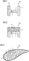
Figur 1 zeigt eine perspektivische Ansicht eines Abschnitts einer Turbinenschaufel des Standes der Technik. Im Speziellen ist ein H-förmiges Profil eines spitzenseitigen Abschnitts der Turbinenschaufel gekennzeichnet, welcher im Folgenden mit dem Bezugszeichen 100 synonym mit der Turbinenschaufel bezeichnet ist. - Weiterhin weist die Turbinenschaufel eine mit dem Bezugszeichen 20 gekennzeichnete Schaufelspitze auf. Synonym mit der Schaufelspitze 20 kann eine Anstreifkante oder eine entsprechende Anstreiffläche bezeichnet sein. Der untere Teil der Turbinenschaufel 100 ist in den vorliegenden Figuren, insbesondere in den Querschnittabbildungen, nicht gezeigt.
- Die Turbinenschaufel 100 weist einen Endabschnitt 1 auf. Der Endabschnitt 1 ist vorzugsweise gegenüber der Schaufelspitze 20 abgesenkt. Der Endabschnitt 1 bezeichnet einen vertikalen Abschnitt des in
Figur 1 gezeigten Profils. Weiterhin weist die Turbinenschaufel einen äußeren Wandabschnitt 2 auf, welcher den Endabschnitt 1 umschließt. Der äußere Wandabschnitt 2 kann auch in mehrere äußere Wandabschnitte 2 unterteilt sein. Durch die Querschnittsdarstellung sind zwei Teile /Bereiche des äußeren Wandabschnitts dargestellt. Der äußere Wandabschnitt erstreckt sich zweckmäßigerweise zwischen dem Endabschnitt 1 und der Schaufelspitze 20. - Weiterhin weist der Endabschnitt 1 eine oder mehrere Kühlluftbohrungen 3 auf. Durch die Kühlluftbohrungen 3 kann vorzugsweise ein Kühlfluid strömen, um die im Betrieb der Turbinenschaufel durch die Betriebstemperaturen hochbelasteten spitzenseitigen Abschnitt der Schaufel zu kühlen. Vorzugsweise stellt der äußere Wandabschnitt 2 eine Verlängerung von Seitenwänden der Turbinenschaufel, insbesondere eine Verlängerung der Druckseite und der Saugseite der Turbinenschaufel dar.
-
Figur 2 zeigt eine schematische Schnittansicht eines spitzenseitigen Abschnitts oder Endabschnitts einer Turbinenschaufel 100 gemäß der vorliegenden Erfindung. Der spitzenseitige Abschnitt kann vorzugsweise zumindest einen Abschnitt der Turbinenschaufel 100 zwischen dem Endabschnitt 1 und der Schaufelspitze 20 bezeichnen. Die Turbinenschaufel 100 bzw. der genannte Abschnitt umfasst zusätzlich zu den inFigur 1 gezeigten Merkmalen eine Kühlstruktur 10. Die Kühlstruktur 10 ist insbesondere zwischen dem Endabschnitt 1 und der Schaufelspitze 20 ausgebildet. Vorzugsweise erstreckt sich die Kühlstruktur 10 über die gesamte Länge zwischen dem Endabschnitt 1 und der Schaufelspitze 20. InFigur 2 erstreckt sich die eigentliche Schaufelspitze 20 bzw. die Anstreifkante oder der Anstreifbereich durch die Ausgestaltung der Kühlstruktur 10 über den gesamten Querschnitt (horizontale Richtung) der Turbinenschaufel 100. - Die Kühlstruktur 10 füllt in
Figur 1 den gesamten Bereich zwischen dem Endabschnitt 1 und dem äußeren Wandabschnitt 2 aus. In diesem Sinne erstreckt sich die Kühlstruktur 10 mit Vorteil ebenfalls im Wesentlichen über die gesamte Breite der Querschnittsdarstellung ausFigur 1 , das heißt über die gesamte Breite der Turbinenschaufel zwischen den gezeigten äußeren Wandabschnitten 2. - Die Kühlstruktur 10 umfasst eine Mehrzahl von Kühlkanälen 5, welche ausgebildet sind, im Betrieb der Turbinenschaufel zur Kühlung der Turbinenschaufel 100 und/oder des gesamten bezeichneten Abschnitts von einem Kühlfluid (nicht explizit gekennzeichnet) durchströmt zu werden. Bei dem Kühlfluid handelt es sich zweckmäßigerweise um ein Prozessgas mit einer Temperatur unterhalb einer Heißgas- oder Betriebstemperatur der entsprechenden Turbine.
- In
Figur 2 sind in die Kühlkanäle durch eine Gitterstruktur gebildet, das heißt es handelt sich um offene oder untereinander zumindest teilweise fluidisch verbundene Kanäle. Das genannte Gitter kann ebenfalls lediglich aus Streben oder einem entsprechenden Raster bestehen, sodass ein großes Kanalvolumen zur Kühlung der Turbinenschaufel 100 dienen kann. - Die einzelnen Kühlkanäle können, beispielsweise durch die Rastergrößen des Gitters, einen Durchmesser oder eine Abmessung zwischen 0,1 mm und 1 mm haben.
- Die äußeren Wandabschnitte 2 sind erfindungsgemäß vorzugsweise geschlossene Wandabschnitte. Jedoch kann innerhalb der äußeren Wandabschnitte 2 im Rahmen der vorliegenden Erfindung die Kühlstruktur 10 zumindest teilweise ausgebildet sein (vergleiche
Figuren 8 bis 10 weiter unten). InFigur 2 sind die äußeren Wandabschnitte vorzugsweise durchgehende, nicht von der Kühlstruktur 10 durchsetzte, Wandabschnitte. - Erfindungsgemäß können - abweichend von der Darstellung der
Figur 1 - eine Mehrzahl von Kühlluftbohrungen 3 im Endabschnitt 1 der Turbinenschaufel 100 vorgesehen und ausgebildet sein, um, im Betrieb der Turbinenschaufel 100 von einem Kühlfluid von (radial) innen nach (radial) außen durchströmt zu werden (das heißt von unten nach oben inFigur 2 ). Dadurch wird insbesondere eine Prallkühlung für die Kühlung des Endabschnitts 1 realisiert. - Im Betrieb der Turbinenschaufel 100 wird nun vorzugsweise das Kühlfluid von innen durch die Kühlluftbohrungen 3 geführt, wobei es anschließend die Kühlstruktur 10 durchströmt und den Bereich der Turbinenschaufel zwischen Endabschnitt 1 und Schaufelspitze 20 effektiv kühlt und die Schaufel so vor mechanischem, oxidativem und/oder korrosivem Verschleiß, schützt. Diese Kühlung ist insbesondere deshalb so effektiv, da die Kühlstruktur eine große Kühloberfläche bildet und gleichzeitig das Kühlfluid durch vorteilhaft große Durchmesser der Kühlkanäle wenig Widerstand erfährt.
- Die Kühlstruktur 10 wird durch ein additives oder generatives Herstellungsverfahren vorzugsweise anschließend an einen Aufbau der restlichen oder Basisstruktur für die Turbinenschaufel, hergestellt. Besonders bevorzugt ist die Kühlstruktur 10 durch selektives Laserschmelzen herstellbar und/oder hergestellt.
- Besonders bevorzugt wird die Kühlstruktur 10 auf oder an dem Endabschnitt von konventionellen Turbinenschaufeln in einem Wartung- oder Instandsetzungsschritt aufgebaut ("refurbishment"). Die Kühlstruktur wird auf dem Endabschnitt vorzugsweise derart additiv aufgebaut, dass die Kühlkanäle gebildet werden. Gemäß dem beschriebenen Verfahren wird die Kühlstruktur vorzugsweise in radialer Richtung mit einem Übermaß aufgebaut, sodass sich die zweckmäßige Länge der gesamten Turbinenschaufel durch Abrasion (automatisch) einstellen kann. Eine abrasive Abdichtung der Radialspalte von Turbinenschaufeln im Allgemeinen ist im Stand der Technik bereits bekannt.
- Dieses Verfahren ermöglicht weiterhin vorteilhafterweise die Verarbeitung der für Turbinenschaufeln benötigten Materialien, wie beispielsweise nickel- oder kobaltbasierte Superlegierungen.
-
Figur 3 zeigt eine schematische Aufsicht auf die Schaufelspitze 20 der inFigur 2 dargestellten Turbinenschaufel 100. InFigur 3 ist insbesondere ein Querschnitt (entlang einer Längsachse der Turbinenschaufel 100) oder eine Aufsicht auf die Turbinenschaufel 100 dargestellt, wobei das Profil der Turbinenschaufel erkennbar ist. Der äußere Wandabschnitt 2 bzw. eine Außenwand der Turbinenschaufel ist annähernd umfänglich dargestellt, wobei diese lediglich an einer Abströmkante (nicht explizit dargestellt) der Turbinenschaufel 100 unterbrochen sein kann. -
Figur 4 zeigt eine schematische Schnittansicht eines spitzenseitigen Abschnitts einer Turbinenschaufel 100 gemäß einer weiteren Ausgestaltung der vorliegenden Erfindung. Zusätzlich zur Darstellung ausFigur 2 sind beispielhaft zwei innere Wände 4 dargestellt, welche als zusätzliche Anstreifkante an der Schaufelspitze 20 fungieren können. Im Querschnitt der Turbinenschaufel 100 betrachtet sind die inneren Wände zweckmäßigerweise innerhalb des äußeren Wandabschnitts 2 angeordnet. - Durch diese Ausgestaltung kann die Anstreifkante der Turbinenschaufel insgesamt besonders zweckmäßig vor mechanischen Einflüssen und folglich vor einem Verschleiß bewahrt werden. Obwohl dies nicht explizit dargestellt ist, können weitere innere Wände vorgesehen sein, um zusätzliche erfinderische Vorteile zu bieten. Zweckmäßigerweise sind die inneren Wände 4 derart auf dem Endabschnitt 1 angeordnet, dass die Kühlluftbohrungen nicht überdeckt werden. Die innere Wand 4 erstreckt sich - wie dargestellt - von dem Endabschnitt in radialer Richtung zweckmäßigerweise bis zur Schaufelspitze 20.
- Weiterhin ist in
Figur 4 gezeigt, dass die Turbinenschaufel, insbesondere mindestens der äußere Wandabschnitt 2, die Schaufelspitze 20, und die Kühlstruktur 10 mit einer Beschichtung 7 versehen sind. Bei der Beschichtung 7 handelt es sich vorzugsweise um eine Wärmedämm- und/oder Oxidationsschutzbeschichtung. Es kann sich weiterhin um eine Vielfachbeschichtung handeln, beispielsweise mit einer ersten, inneren Schicht als Oxidationsschutz, insbesondere mit Materialien umfassend MAX-Phasen und/oder MCrAlY-Legierungen, und einer zweiten, äußeren Schicht zur Wärmedämmung. -
Figur 5 zeigt eine schematische Aufsicht auf die Schaufelspitze 20 der inFigur 4 dargestellten Turbinenschaufel 100. - Entsprechend der Darstellung aus
Figur 4 sind zwei, zwischen Druck- und Saugseite der Turbinenschaufel (unten und oben) angeordnete, innere Wände 4, gekennzeichnet. -
Figur 6 zeigt eine schematische Schnittansicht eines schaufelseitigen Abschnitts einer Turbinenschaufel 100 gemäß einer beispielhaften Ausgestaltung, die nicht unter den Schutzempfang fällt und lediglich zur zusätzlichen Erläuterung präsentiert wird. Gemäß dieser Darstellung ist die Kühlstruktur 10 durch eine unregelmäßig geformte, insbesondere bionische oder biomimetisch optimierte oder gestaltete Geometrie geformt. Diese kann beispielsweise ein Ergebnis eines Simulationsverfahrens oder eines Optimierungsverfahrens, beispielsweise umfassend genetische Algorithmen und/oder vergleichbare "Trial-and-Error" Optimierungsschritte, sein. Insbesondere können Parameter, wie der Fluidwiderstand, die mechanische Stabilität der Kühlstruktur und/oder der Anstreifkante, oder die thermische, mechanische, thermomechanische, oxidative oder korrosiv Belastung während des Betriebs der Turbinenschaufel 100, für das Design der Geometrie optimiert sein. Weiterhin ist inFigur 6 zu erkennen, dass die äußeren Wandabschnitte 2 weiterhin durchgängig geschlossen dargestellt sind, sodass kein Kühlkanal der Kühlstruktur 10 in den äußeren Wandabschnitten 2 endet oder mündet. Alternativ zu dieser Ausgestaltung können die Kühlkanäle 5 jedoch auch in den äußeren Wandabschnitten 2 münden oder enden. -
Figur 7 zeigt eine schematische Aufsicht auf die Schaufelspitze 20 der inFigur 6 dargestellten Turbinenschaufel 100. InFigur 7 ist insbesondere zu erkennen, dass die unregelmäßige, bionische Geometrie der Kühlstruktur 10 gemäß dieser Ausgestaltung ebenfalls über den gesamten Querschnitt der Turbinenschaufel 100 verteilt ist oder sich darüber erstreckt. -
Figur 8 zeigt eine schematische Schnittansicht eines spitzenseitigen Abschnitts einer Turbinenschaufel 100 gemäß einer weiteren beispielhaften Ausgestaltung, die nicht unter den Schutzempfang der Erfindung fällt. Alternativ zu den oben beschriebenen Figuren ist die Kühlstruktur 10 gemäß dieser Ausgestaltung beispielsweise zumindest teilweise in den äußeren Wandabschnitten ausgebildet. Als weiterer Unterschied ist die Kühlstruktur lediglich im Bereich der Wandabschnitte 2 und in Form von geschlossenen oder fluidisch zumindest teilweise voneinander getrennten Kühlkanälen 5 ausgebildet. Die Kühlstruktur 10 bzw. die Kühlkanäle 5 sind jedoch derart ausgebildet, dass Auslässe oder Austrittsöffnungen 6 der Kühlkanäle 5 - ebenso wie in den oben beschriebenen Beispielen - in der Anstreifkante und/oder der Schaufelspitze 20 münden oder enden. - Es ist weiterhin zu erkennen, dass die Kühlluftbohrungen 3 an jeder Seite des gezeigten Querschnitts jeweils in einer Kanalstruktur (nicht explizit gekennzeichnet), das heißt in einem oder mehreren, jeweils zumindest teilweise voneinander fluidisch getrennten, Kühlkanälen mündet. Durch diese Ausgestaltung kann die "Kühlgeometrie" spezifisch auf bestimmte während des Betriebs der Turbinenschaufel 100 auftretende "Hot-spots" abgestimmt werden.
- Die einzelnen Kühlkanäle können, gemäß dieser Ausgestaltung beispielsweise jeweils Durchmesser oder Abmessungen zwischen 0,1 mm und 1 mm haben.
-
Figur 9 zeigt schematisch einen Querschnitt eines Teils einer Turbinenschaufel aus einer im Vergleich zurFigur 8 alternativen Perspektive, beispielsweise entlang einer anderen Achse geschnitten. Die Darstellung ausFigur 9 ist insbesondere derart zu verstehen, dass sich jeweils ein Kühlkanal 5 (wie oben beschrieben) an jeweils eine Kühlluftbohrung 3 (vergleicheFigur 8 ) anschließt und dieser Kühlkanal 5 sich dann innerhalb einer des äußeren Wandabschnitts 2 erstreckt, wobei lediglich der Auslass 6 an der Oberfläche der Schaufelspitze 20 bzw. der Anstreifkante angeordnet ist, sodass das Kühlfluid jeweils auch lediglich durch den Auslass 6 aus der Kühlstruktur 10 austreten kann. Weiterhin ist zu erkennen, dass sich die Kühlkanäle 5 vorzugsweise im Wesentlichen über den gesamten Querschnitt und/oder die gesamte bereitgestellte Fläche der Schaufelspitze 20 bzw. eines Anstreifbereichs erstrecken. - Merkmale oder Ausgestaltungen der unterschiedlichen Ausführungsbeispiele können vorliegend zur Lösung der erfinderischen Aufgabe miteinander kombiniert werden. So kann beispielsweise eine Turbinenschaufel vorgesehen sein, bei der zusätzlich zu der in den
Figuren 8 und 9 dargestellten "Kanal-Kühlstruktur" eine "Gitter-Kühlstruktur", wie in den Figuren 2 bis 5 beschrieben, vorhanden ist, ohne von dem Erfindungsgedanken abzuweichen. - Die Erfindung ist nicht durch die Beschreibung anhand der Ausführungsbeispiele auf diese beschränkt, sondern umfasst jedes neue Merkmal sowie jede Kombination von Merkmalen. Dies beinhaltet insbesondere jede Kombination von Merkmalen in den Patentansprüchen, auch wenn dieses Merkmal oder diese Kombination selbst nicht explizit in den Patentansprüchen oder Ausführungsbeispielen angegeben ist.
Claims (11)
- Turbinenschaufel (100) umfassend:- eine Schaufelspitze (20),- eine Kühlstruktur (10) umfassend Kühlkanäle (5), welche ausgebildet sind, zur Kühlung der Turbinenschaufel (100) im Betrieb von einem Kühlfluid durchströmt zu werden,- einen gegenüber der Schaufelspitze (20) abgesenkten Endabschnitt (1) und- einen äußeren Wandabschnitt (2), welcher sich bis zur Schaufelspitze (20) erstreckt, wobei die Kühlstruktur (10) zwischen dem Endabschnitt (1) und der Schaufelspitze (20) ausgebildet ist, derart, dass sich die Kühlstruktur (10) von dem Endabschnitt (1) bis zur Schaufelspitze (20) erstreckt, dadurch gekennzeichnet, dass die Kühlstruktur (10) eine Gitterstruktur umfasst, welche die Kühlkanäle (5) bildet.
- Turbinenschaufel (100) gemäß Anspruch 1, wobei Durchmesser der Kühlkanäle (5) zwischen 0,1 mm und 1 mm liegen.
- Turbinenschaufel (100) gemäß Anspruch 1 oder 2, wobei die Kühlstruktur eine Mehrzahl von voneinander fluidisch getrennten Kühlkanälen (5) umfasst.
- Turbinenschaufel (100) gemäß einem der vorhergehenden Ansprüche, wobei der Endabschnitt (1) Kühlluftbohrungen (3) aufweist.
- Turbinenschaufel (100) gemäß einem der vorhergehenden Ansprüche, wobei die Kühlstruktur (10) zumindest teilweise in dem äußeren Wandabschnitt (2) ausgebildet ist und wobei ein Auslass (6) der Kühlkanäle in die Schaufelspitze (20) mündet.
- Turbinenschaufel (100) gemäß einem der vorhergehenden Ansprüche, wobei der äußere Wandabschnitt (2) ein geschlossener Wandabschnitt ist und wobei die Kühlstruktur (10) von dem äußeren Wandabschnitt (2) zumindest teilweise umschlossen ist.
- Turbinenschaufel (100) gemäß einem der vorhergehenden Ansprüche, wobei die Turbinenschaufel (100) zwischen der Schaufelspitze (20) und dem Endabschnitt (1) eine Mehrzahl von inneren Wänden (4) umfasst, die sich durch die Kühlstruktur (10) erstrecken.
- Turbinenschaufel (100) gemäß einem der vorhergehenden Ansprüche, wobei die Schaufelspitze (20) eine Wärmedämm- und/oder Oxidationsschutzschicht (7) aufweist.
- Turbinenschaufel (100) gemäß einem der vorhergehenden Ansprüche, wobei die Schaufelspitze (20) und/oder die Kühlstruktur (10) ausgebildet sind, im Betrieb der Turbinenschaufel (100) eine Anstreifkante (2) zu bilden.
- Turbinenschaufel (100), gemäß einem der vorhergehenden Ansprüche, wobei die Kühlstruktur (10) und/oder der äußere Wandabschnitt (2) durch ein additives Herstellungsverfahren, beispielsweise durch selektives Laserschmelzen, hergestellt oder herstellbar sind.
- Verfahren zur Herstellung einer Kühlstruktur (10) für eine Turbinenschaufel (100) gemäß einem der vorhergehenden Ansprüche, umfassend das additive Aufbauen der Kühlstruktur (10) an einem Endabschnitt (1) der Turbinenschaufel (100), wobei die Kühlstruktur (10) auf dem Endabschnitt (1) derart additiv aufgebaut wird, dass Kühlkanäle (5) gebildet werden, welche ausgebildet sind, zur Kühlung der Turbinenschaufel (100) im Betrieb von einem Kühlfluid durchströmt zu werden.
Applications Claiming Priority (2)
| Application Number | Priority Date | Filing Date | Title |
|---|---|---|---|
| DE102016205320.5A DE102016205320A1 (de) | 2016-03-31 | 2016-03-31 | Turbinenschaufel mit Kühlstruktur |
| PCT/EP2017/056790 WO2017167615A1 (de) | 2016-03-31 | 2017-03-22 | Turbinenschaufel mit kühlstruktur und zugehöriges herstellungsverfahren |
Publications (2)
| Publication Number | Publication Date |
|---|---|
| EP3420196A1 EP3420196A1 (de) | 2019-01-02 |
| EP3420196B1 true EP3420196B1 (de) | 2019-11-20 |
Family
ID=58461278
Family Applications (1)
| Application Number | Title | Priority Date | Filing Date |
|---|---|---|---|
| EP17714666.9A Active EP3420196B1 (de) | 2016-03-31 | 2017-03-22 | Turbinenschaufel mit kühlstruktur und zugehöriges herstellungsverfahren |
Country Status (6)
| Country | Link |
|---|---|
| US (1) | US11073022B2 (de) |
| EP (1) | EP3420196B1 (de) |
| CN (1) | CN108884715B (de) |
| CA (1) | CA3019406C (de) |
| DE (1) | DE102016205320A1 (de) |
| WO (1) | WO2017167615A1 (de) |
Families Citing this family (11)
| Publication number | Priority date | Publication date | Assignee | Title |
|---|---|---|---|---|
| US10400608B2 (en) * | 2016-11-23 | 2019-09-03 | General Electric Company | Cooling structure for a turbine component |
| DE102017208707A1 (de) | 2017-05-23 | 2018-11-29 | Siemens Aktiengesellschaft | Verfahren zur Herstellung einer Turbinenschaufel |
| DE102017209421A1 (de) * | 2017-06-02 | 2018-12-06 | MTU Aero Engines AG | Laufschaufel mit Schaufelspitzenkühlung |
| DE102018200287A1 (de) | 2018-01-10 | 2019-07-11 | Siemens Aktiengesellschaft | Turbomaschineninnengehäuse |
| WO2019212478A1 (en) * | 2018-04-30 | 2019-11-07 | Siemens Aktiengesellschaft | Turbine blade tip with multi-outlet cooling channels |
| US11208902B2 (en) | 2018-12-03 | 2021-12-28 | General Electric Company | Tip rail cooling insert for turbine blade tip cooling system and related method |
| US10934852B2 (en) | 2018-12-03 | 2021-03-02 | General Electric Company | Turbine blade tip cooling system including tip rail cooling insert |
| US10982553B2 (en) | 2018-12-03 | 2021-04-20 | General Electric Company | Tip rail with cooling structure using three dimensional unit cells |
| US20240229651A9 (en) * | 2019-10-28 | 2024-07-11 | Siemens Energy Global GmbH & Co. KG | Turbine blade, method of manufacturing a turbine blade and method of refurbishing a turbine blade |
| DE102020105650A1 (de) | 2020-03-03 | 2021-09-09 | Frank Carsten Herzog | Strahllenkeinrichtung zum Lenken wenigstens eines Energiestrahls entlang einer Oberfläche |
| WO2022254648A1 (ja) * | 2021-06-03 | 2022-12-08 | 株式会社ニコン | 造形装置及び造形方法 |
Family Cites Families (15)
| Publication number | Priority date | Publication date | Assignee | Title |
|---|---|---|---|---|
| US3854842A (en) | 1973-04-30 | 1974-12-17 | Gen Electric | Rotor blade having improved tip cap |
| US4411597A (en) * | 1981-03-20 | 1983-10-25 | The United States Of America As Represented By The Administrator Of The National Aeronautics And Space Administration | Tip cap for a rotor blade |
| US4589823A (en) * | 1984-04-27 | 1986-05-20 | General Electric Company | Rotor blade tip |
| US6135715A (en) * | 1999-07-29 | 2000-10-24 | General Electric Company | Tip insulated airfoil |
| DE10104732C1 (de) | 2001-02-02 | 2002-06-27 | Fraunhofer Ges Forschung | Verfahren und Vorrichtung zum selektiven Laser-Schmelzen von metallischen Werkstoffen |
| US6461108B1 (en) * | 2001-03-27 | 2002-10-08 | General Electric Company | Cooled thermal barrier coating on a turbine blade tip |
| EP1462613A1 (de) | 2003-03-26 | 2004-09-29 | Siemens Aktiengesellschaft | Kühlbares Schichtsystem |
| US8083484B2 (en) | 2008-12-26 | 2011-12-27 | General Electric Company | Turbine rotor blade tips that discourage cross-flow |
| US8366394B1 (en) * | 2010-10-21 | 2013-02-05 | Florida Turbine Technologies, Inc. | Turbine blade with tip rail cooling channel |
| US9133712B2 (en) * | 2012-04-24 | 2015-09-15 | United Technologies Corporation | Blade having porous, abradable element |
| US9097126B2 (en) * | 2012-09-12 | 2015-08-04 | General Electric Company | System and method for airfoil cover plate |
| US20150034266A1 (en) * | 2013-08-01 | 2015-02-05 | Siemens Energy, Inc. | Building and repair of hollow components |
| US9879544B2 (en) * | 2013-10-16 | 2018-01-30 | Honeywell International Inc. | Turbine rotor blades with improved tip portion cooling holes |
| EP2863012A1 (de) | 2013-10-18 | 2015-04-22 | Siemens Aktiengesellschaft | Turbinenschaufel mit Lamellenstruktur und Verfahren zur Herstellung |
| US10400608B2 (en) * | 2016-11-23 | 2019-09-03 | General Electric Company | Cooling structure for a turbine component |
-
2016
- 2016-03-31 DE DE102016205320.5A patent/DE102016205320A1/de not_active Withdrawn
-
2017
- 2017-03-22 US US16/083,989 patent/US11073022B2/en active Active
- 2017-03-22 EP EP17714666.9A patent/EP3420196B1/de active Active
- 2017-03-22 WO PCT/EP2017/056790 patent/WO2017167615A1/de not_active Ceased
- 2017-03-22 CA CA3019406A patent/CA3019406C/en active Active
- 2017-03-22 CN CN201780022120.3A patent/CN108884715B/zh active Active
Non-Patent Citations (1)
| Title |
|---|
| None * |
Also Published As
| Publication number | Publication date |
|---|---|
| CA3019406C (en) | 2020-10-27 |
| CN108884715A (zh) | 2018-11-23 |
| DE102016205320A1 (de) | 2017-10-05 |
| EP3420196A1 (de) | 2019-01-02 |
| US20200291788A1 (en) | 2020-09-17 |
| CA3019406A1 (en) | 2017-10-05 |
| US11073022B2 (en) | 2021-07-27 |
| WO2017167615A1 (de) | 2017-10-05 |
| CN108884715B (zh) | 2021-07-27 |
Similar Documents
| Publication | Publication Date | Title |
|---|---|---|
| WO2017167615A1 (de) | Turbinenschaufel mit kühlstruktur und zugehöriges herstellungsverfahren | |
| EP3191244B1 (de) | Verfahren zur herstellung einer laufschaufel und so erhaltene schaufel | |
| EP2815083B1 (de) | Bauteil für eine thermische maschine, insbesondere eine gasturbine | |
| EP3054106B1 (de) | Gasturbinenbauteil | |
| DE102009033835B4 (de) | Verfahren zum Austauschen einer Schaufel eines Rotors mit integrierter Beschaufelung und ein derartiger Rotor | |
| WO2011054342A1 (de) | Blisk, gasturbine und verfahren zur herstellung einer derartigen blisk | |
| DE102015210744A1 (de) | Verfahren zum Fertigen einer Turbinenschaufel | |
| EP3456923B1 (de) | Schaufel einer strömungsmaschine mit kühlkanal und darin angeordnetem verdrängungskörper sowie verfahren zur herstellung | |
| DE102013205883B4 (de) | Anordnung aus Leitschaufelsegmenten und Verfahren zur Herstellung einer derartigen Anordnung | |
| EP3473808B1 (de) | Schaufelblatt für eine innengekühlte turbinenlaufschaufel sowie verfahren zur herstellung einer solchen | |
| EP3704386B1 (de) | Generativ gefertigter zwischenkanal zur anordnung zwischen einem niederdruckverdichter und einem hochdruckverdichter, sowie entsprechendes fertigungsverfahren | |
| WO2020157190A1 (de) | Gasturbinen-heissgas-bauteil und verfahren zum herstellen eines derartigen gasturbinen-heissgas-bauteils | |
| EP3260664A1 (de) | Verdickter radial äusserer ringbereich eines dichtfins | |
| EP2496793B1 (de) | Geschweisster rotor eines gasturbinentriebwerkverdichters | |
| DE102010049541B4 (de) | Laufschaufel für eine Strömungsmaschine | |
| EP2871418B1 (de) | Gasturbinenbrennkammer sowie Verfahren zu deren Herstellung | |
| EP3156588B1 (de) | Reparaturverfahren für dichtsegmente | |
| EP3508690A1 (de) | Turbinenschaufelblatt, turbinenschaufel und verfahren zu deren herstellung | |
| EP2404036A1 (de) | Verfahren zur herstellung eines integral beschaufelten rotors | |
| EP1355041A2 (de) | Turbinenschaufel | |
| EP2860352A1 (de) | Rotor, zugehöriges Herstellungsverfahren und Laufschaufel | |
| EP2848770B1 (de) | Laufradschaufel einer axialen Strömungsmaschine und Dämpfungselement | |
| EP3983225A1 (de) | Komponente mit einem zu kühlenden bereich und mittel zur additiven herstellung derselben | |
| DE102011102251A1 (de) | Verfahren zur Herstellung einer integral beschaufelten Rotorscheibe, integral beschaufelte Rotorscheibe, Rotor und Strömungsmaschine | |
| EP2350440B1 (de) | Verfahren zur optimierung der kontaktflächen von aneinander anstossenden deckbandsegmenten benachbarter schaufeln einer gasturbine |
Legal Events
| Date | Code | Title | Description |
|---|---|---|---|
| STAA | Information on the status of an ep patent application or granted ep patent |
Free format text: STATUS: UNKNOWN |
|
| STAA | Information on the status of an ep patent application or granted ep patent |
Free format text: STATUS: THE INTERNATIONAL PUBLICATION HAS BEEN MADE |
|
| PUAI | Public reference made under article 153(3) epc to a published international application that has entered the european phase |
Free format text: ORIGINAL CODE: 0009012 |
|
| STAA | Information on the status of an ep patent application or granted ep patent |
Free format text: STATUS: REQUEST FOR EXAMINATION WAS MADE |
|
| 17P | Request for examination filed |
Effective date: 20180925 |
|
| AK | Designated contracting states |
Kind code of ref document: A1 Designated state(s): AL AT BE BG CH CY CZ DE DK EE ES FI FR GB GR HR HU IE IS IT LI LT LU LV MC MK MT NL NO PL PT RO RS SE SI SK SM TR |
|
| AX | Request for extension of the european patent |
Extension state: BA ME |
|
| DAV | Request for validation of the european patent (deleted) | ||
| DAX | Request for extension of the european patent (deleted) | ||
| GRAP | Despatch of communication of intention to grant a patent |
Free format text: ORIGINAL CODE: EPIDOSNIGR1 |
|
| STAA | Information on the status of an ep patent application or granted ep patent |
Free format text: STATUS: GRANT OF PATENT IS INTENDED |
|
| INTG | Intention to grant announced |
Effective date: 20190711 |
|
| GRAS | Grant fee paid |
Free format text: ORIGINAL CODE: EPIDOSNIGR3 |
|
| GRAA | (expected) grant |
Free format text: ORIGINAL CODE: 0009210 |
|
| STAA | Information on the status of an ep patent application or granted ep patent |
Free format text: STATUS: THE PATENT HAS BEEN GRANTED |
|
| AK | Designated contracting states |
Kind code of ref document: B1 Designated state(s): AL AT BE BG CH CY CZ DE DK EE ES FI FR GB GR HR HU IE IS IT LI LT LU LV MC MK MT NL NO PL PT RO RS SE SI SK SM TR |
|
| REG | Reference to a national code |
Ref country code: GB Ref legal event code: FG4D Free format text: NOT ENGLISH |
|
| REG | Reference to a national code |
Ref country code: CH Ref legal event code: EP |
|
| REG | Reference to a national code |
Ref country code: IE Ref legal event code: FG4D Free format text: LANGUAGE OF EP DOCUMENT: GERMAN |
|
| REG | Reference to a national code |
Ref country code: AT Ref legal event code: REF Ref document number: 1204425 Country of ref document: AT Kind code of ref document: T Effective date: 20191215 |
|
| REG | Reference to a national code |
Ref country code: DE Ref legal event code: R096 Ref document number: 502017002938 Country of ref document: DE |
|
| REG | Reference to a national code |
Ref country code: CH Ref legal event code: NV Representative=s name: SIEMENS SCHWEIZ AG, CH |
|
| REG | Reference to a national code |
Ref country code: SE Ref legal event code: TRGR |
|
| REG | Reference to a national code |
Ref country code: LT Ref legal event code: MG4D |
|
| PG25 | Lapsed in a contracting state [announced via postgrant information from national office to epo] |
Ref country code: LV Free format text: LAPSE BECAUSE OF FAILURE TO SUBMIT A TRANSLATION OF THE DESCRIPTION OR TO PAY THE FEE WITHIN THE PRESCRIBED TIME-LIMIT Effective date: 20191120 Ref country code: NO Free format text: LAPSE BECAUSE OF FAILURE TO SUBMIT A TRANSLATION OF THE DESCRIPTION OR TO PAY THE FEE WITHIN THE PRESCRIBED TIME-LIMIT Effective date: 20200220 Ref country code: LT Free format text: LAPSE BECAUSE OF FAILURE TO SUBMIT A TRANSLATION OF THE DESCRIPTION OR TO PAY THE FEE WITHIN THE PRESCRIBED TIME-LIMIT Effective date: 20191120 Ref country code: GR Free format text: LAPSE BECAUSE OF FAILURE TO SUBMIT A TRANSLATION OF THE DESCRIPTION OR TO PAY THE FEE WITHIN THE PRESCRIBED TIME-LIMIT Effective date: 20200221 Ref country code: FI Free format text: LAPSE BECAUSE OF FAILURE TO SUBMIT A TRANSLATION OF THE DESCRIPTION OR TO PAY THE FEE WITHIN THE PRESCRIBED TIME-LIMIT Effective date: 20191120 Ref country code: BG Free format text: LAPSE BECAUSE OF FAILURE TO SUBMIT A TRANSLATION OF THE DESCRIPTION OR TO PAY THE FEE WITHIN THE PRESCRIBED TIME-LIMIT Effective date: 20200220 |
|
| REG | Reference to a national code |
Ref country code: NL Ref legal event code: FP |
|
| PG25 | Lapsed in a contracting state [announced via postgrant information from national office to epo] |
Ref country code: HR Free format text: LAPSE BECAUSE OF FAILURE TO SUBMIT A TRANSLATION OF THE DESCRIPTION OR TO PAY THE FEE WITHIN THE PRESCRIBED TIME-LIMIT Effective date: 20191120 Ref country code: RS Free format text: LAPSE BECAUSE OF FAILURE TO SUBMIT A TRANSLATION OF THE DESCRIPTION OR TO PAY THE FEE WITHIN THE PRESCRIBED TIME-LIMIT Effective date: 20191120 Ref country code: IS Free format text: LAPSE BECAUSE OF FAILURE TO SUBMIT A TRANSLATION OF THE DESCRIPTION OR TO PAY THE FEE WITHIN THE PRESCRIBED TIME-LIMIT Effective date: 20200320 |
|
| PG25 | Lapsed in a contracting state [announced via postgrant information from national office to epo] |
Ref country code: AL Free format text: LAPSE BECAUSE OF FAILURE TO SUBMIT A TRANSLATION OF THE DESCRIPTION OR TO PAY THE FEE WITHIN THE PRESCRIBED TIME-LIMIT Effective date: 20191120 |
|
| PG25 | Lapsed in a contracting state [announced via postgrant information from national office to epo] |
Ref country code: CZ Free format text: LAPSE BECAUSE OF FAILURE TO SUBMIT A TRANSLATION OF THE DESCRIPTION OR TO PAY THE FEE WITHIN THE PRESCRIBED TIME-LIMIT Effective date: 20191120 Ref country code: RO Free format text: LAPSE BECAUSE OF FAILURE TO SUBMIT A TRANSLATION OF THE DESCRIPTION OR TO PAY THE FEE WITHIN THE PRESCRIBED TIME-LIMIT Effective date: 20191120 Ref country code: DK Free format text: LAPSE BECAUSE OF FAILURE TO SUBMIT A TRANSLATION OF THE DESCRIPTION OR TO PAY THE FEE WITHIN THE PRESCRIBED TIME-LIMIT Effective date: 20191120 Ref country code: EE Free format text: LAPSE BECAUSE OF FAILURE TO SUBMIT A TRANSLATION OF THE DESCRIPTION OR TO PAY THE FEE WITHIN THE PRESCRIBED TIME-LIMIT Effective date: 20191120 Ref country code: PT Free format text: LAPSE BECAUSE OF FAILURE TO SUBMIT A TRANSLATION OF THE DESCRIPTION OR TO PAY THE FEE WITHIN THE PRESCRIBED TIME-LIMIT Effective date: 20200412 Ref country code: ES Free format text: LAPSE BECAUSE OF FAILURE TO SUBMIT A TRANSLATION OF THE DESCRIPTION OR TO PAY THE FEE WITHIN THE PRESCRIBED TIME-LIMIT Effective date: 20191120 |
|
| REG | Reference to a national code |
Ref country code: DE Ref legal event code: R097 Ref document number: 502017002938 Country of ref document: DE |
|
| PG25 | Lapsed in a contracting state [announced via postgrant information from national office to epo] |
Ref country code: SK Free format text: LAPSE BECAUSE OF FAILURE TO SUBMIT A TRANSLATION OF THE DESCRIPTION OR TO PAY THE FEE WITHIN THE PRESCRIBED TIME-LIMIT Effective date: 20191120 Ref country code: SM Free format text: LAPSE BECAUSE OF FAILURE TO SUBMIT A TRANSLATION OF THE DESCRIPTION OR TO PAY THE FEE WITHIN THE PRESCRIBED TIME-LIMIT Effective date: 20191120 |
|
| PLBE | No opposition filed within time limit |
Free format text: ORIGINAL CODE: 0009261 |
|
| STAA | Information on the status of an ep patent application or granted ep patent |
Free format text: STATUS: NO OPPOSITION FILED WITHIN TIME LIMIT |
|
| 26N | No opposition filed |
Effective date: 20200821 |
|
| PG25 | Lapsed in a contracting state [announced via postgrant information from national office to epo] |
Ref country code: MC Free format text: LAPSE BECAUSE OF FAILURE TO SUBMIT A TRANSLATION OF THE DESCRIPTION OR TO PAY THE FEE WITHIN THE PRESCRIBED TIME-LIMIT Effective date: 20191120 |
|
| PG25 | Lapsed in a contracting state [announced via postgrant information from national office to epo] |
Ref country code: SI Free format text: LAPSE BECAUSE OF FAILURE TO SUBMIT A TRANSLATION OF THE DESCRIPTION OR TO PAY THE FEE WITHIN THE PRESCRIBED TIME-LIMIT Effective date: 20191120 Ref country code: PL Free format text: LAPSE BECAUSE OF FAILURE TO SUBMIT A TRANSLATION OF THE DESCRIPTION OR TO PAY THE FEE WITHIN THE PRESCRIBED TIME-LIMIT Effective date: 20191120 |
|
| REG | Reference to a national code |
Ref country code: DE Ref legal event code: R081 Ref document number: 502017002938 Country of ref document: DE Owner name: SIEMENS ENERGY GLOBAL GMBH & CO. KG, DE Free format text: FORMER OWNER: SIEMENS AKTIENGESELLSCHAFT, 80333 MUENCHEN, DE |
|
| REG | Reference to a national code |
Ref country code: BE Ref legal event code: MM Effective date: 20200331 |
|
| PG25 | Lapsed in a contracting state [announced via postgrant information from national office to epo] |
Ref country code: LU Free format text: LAPSE BECAUSE OF NON-PAYMENT OF DUE FEES Effective date: 20200322 |
|
| PG25 | Lapsed in a contracting state [announced via postgrant information from national office to epo] |
Ref country code: FR Free format text: LAPSE BECAUSE OF NON-PAYMENT OF DUE FEES Effective date: 20200331 Ref country code: IE Free format text: LAPSE BECAUSE OF NON-PAYMENT OF DUE FEES Effective date: 20200322 |
|
| PG25 | Lapsed in a contracting state [announced via postgrant information from national office to epo] |
Ref country code: BE Free format text: LAPSE BECAUSE OF NON-PAYMENT OF DUE FEES Effective date: 20200331 |
|
| PG25 | Lapsed in a contracting state [announced via postgrant information from national office to epo] |
Ref country code: TR Free format text: LAPSE BECAUSE OF FAILURE TO SUBMIT A TRANSLATION OF THE DESCRIPTION OR TO PAY THE FEE WITHIN THE PRESCRIBED TIME-LIMIT Effective date: 20191120 Ref country code: MT Free format text: LAPSE BECAUSE OF FAILURE TO SUBMIT A TRANSLATION OF THE DESCRIPTION OR TO PAY THE FEE WITHIN THE PRESCRIBED TIME-LIMIT Effective date: 20191120 Ref country code: CY Free format text: LAPSE BECAUSE OF FAILURE TO SUBMIT A TRANSLATION OF THE DESCRIPTION OR TO PAY THE FEE WITHIN THE PRESCRIBED TIME-LIMIT Effective date: 20191120 |
|
| PG25 | Lapsed in a contracting state [announced via postgrant information from national office to epo] |
Ref country code: MK Free format text: LAPSE BECAUSE OF FAILURE TO SUBMIT A TRANSLATION OF THE DESCRIPTION OR TO PAY THE FEE WITHIN THE PRESCRIBED TIME-LIMIT Effective date: 20191120 |
|
| REG | Reference to a national code |
Ref country code: GB Ref legal event code: 732E Free format text: REGISTERED BETWEEN 20220901 AND 20220907 |
|
| REG | Reference to a national code |
Ref country code: NL Ref legal event code: PD Owner name: SIEMENS ENERGY GLOBAL GMBH & CO. KG; DE Free format text: DETAILS ASSIGNMENT: CHANGE OF OWNER(S), ASSIGNMENT; FORMER OWNER NAME: SIEMENS AKTIENGESELLSCHAFT Effective date: 20221220 |
|
| REG | Reference to a national code |
Ref country code: AT Ref legal event code: MM01 Ref document number: 1204425 Country of ref document: AT Kind code of ref document: T Effective date: 20220322 |
|
| PGFP | Annual fee paid to national office [announced via postgrant information from national office to epo] |
Ref country code: IT Payment date: 20230321 Year of fee payment: 7 Ref country code: GB Payment date: 20230321 Year of fee payment: 7 Ref country code: DE Payment date: 20220617 Year of fee payment: 7 |
|
| PGFP | Annual fee paid to national office [announced via postgrant information from national office to epo] |
Ref country code: NL Payment date: 20230323 Year of fee payment: 7 |
|
| PG25 | Lapsed in a contracting state [announced via postgrant information from national office to epo] |
Ref country code: AT Free format text: LAPSE BECAUSE OF NON-PAYMENT OF DUE FEES Effective date: 20220322 |
|
| PGFP | Annual fee paid to national office [announced via postgrant information from national office to epo] |
Ref country code: CH Payment date: 20230402 Year of fee payment: 7 |
|
| REG | Reference to a national code |
Ref country code: DE Ref legal event code: R119 Ref document number: 502017002938 Country of ref document: DE |
|
| REG | Reference to a national code |
Ref country code: CH Ref legal event code: PL |
|
| REG | Reference to a national code |
Ref country code: NL Ref legal event code: MM Effective date: 20240401 |
|
| GBPC | Gb: european patent ceased through non-payment of renewal fee |
Effective date: 20240322 |
|
| PG25 | Lapsed in a contracting state [announced via postgrant information from national office to epo] |
Ref country code: NL Free format text: LAPSE BECAUSE OF NON-PAYMENT OF DUE FEES Effective date: 20240401 |
|
| PG25 | Lapsed in a contracting state [announced via postgrant information from national office to epo] |
Ref country code: NL Free format text: LAPSE BECAUSE OF NON-PAYMENT OF DUE FEES Effective date: 20240401 |
|
| PG25 | Lapsed in a contracting state [announced via postgrant information from national office to epo] |
Ref country code: DE Free format text: LAPSE BECAUSE OF NON-PAYMENT OF DUE FEES Effective date: 20241001 |
|
| PG25 | Lapsed in a contracting state [announced via postgrant information from national office to epo] |
Ref country code: GB Free format text: LAPSE BECAUSE OF NON-PAYMENT OF DUE FEES Effective date: 20240322 |
|
| PG25 | Lapsed in a contracting state [announced via postgrant information from national office to epo] |
Ref country code: GB Free format text: LAPSE BECAUSE OF NON-PAYMENT OF DUE FEES Effective date: 20240322 Ref country code: DE Free format text: LAPSE BECAUSE OF NON-PAYMENT OF DUE FEES Effective date: 20241001 Ref country code: CH Free format text: LAPSE BECAUSE OF NON-PAYMENT OF DUE FEES Effective date: 20240331 |
|
| PG25 | Lapsed in a contracting state [announced via postgrant information from national office to epo] |
Ref country code: IT Free format text: LAPSE BECAUSE OF NON-PAYMENT OF DUE FEES Effective date: 20240322 |
|
| PGFP | Annual fee paid to national office [announced via postgrant information from national office to epo] |
Ref country code: SE Payment date: 20260323 Year of fee payment: 10 |