EP3419745B1 - Sight glass - Google Patents
Sight glass Download PDFInfo
- Publication number
- EP3419745B1 EP3419745B1 EP17757124.7A EP17757124A EP3419745B1 EP 3419745 B1 EP3419745 B1 EP 3419745B1 EP 17757124 A EP17757124 A EP 17757124A EP 3419745 B1 EP3419745 B1 EP 3419745B1
- Authority
- EP
- European Patent Office
- Prior art keywords
- window
- frame
- sight glass
- glass
- mating surface
- Prior art date
- Legal status (The legal status is an assumption and is not a legal conclusion. Google has not performed a legal analysis and makes no representation as to the accuracy of the status listed.)
- Active
Links
Images


Classifications
-
- G—PHYSICS
- G02—OPTICS
- G02B—OPTICAL ELEMENTS, SYSTEMS OR APPARATUS
- G02B7/00—Mountings, adjusting means, or light-tight connections, for optical elements
- G02B7/007—Pressure-resistant sight glasses
-
- B—PERFORMING OPERATIONS; TRANSPORTING
- B01—PHYSICAL OR CHEMICAL PROCESSES OR APPARATUS IN GENERAL
- B01J—CHEMICAL OR PHYSICAL PROCESSES, e.g. CATALYSIS OR COLLOID CHEMISTRY; THEIR RELEVANT APPARATUS
- B01J3/00—Processes of utilising sub-atmospheric or super-atmospheric pressure to effect chemical or physical change of matter; Apparatus therefor
- B01J3/004—Sight-glasses therefor
-
- F—MECHANICAL ENGINEERING; LIGHTING; HEATING; WEAPONS; BLASTING
- F23—COMBUSTION APPARATUS; COMBUSTION PROCESSES
- F23M—CASINGS, LININGS, WALLS OR DOORS SPECIALLY ADAPTED FOR COMBUSTION CHAMBERS, e.g. FIREBRIDGES; DEVICES FOR DEFLECTING AIR, FLAMES OR COMBUSTION PRODUCTS IN COMBUSTION CHAMBERS; SAFETY ARRANGEMENTS SPECIALLY ADAPTED FOR COMBUSTION APPARATUS; DETAILS OF COMBUSTION CHAMBERS, NOT OTHERWISE PROVIDED FOR
- F23M11/00—Safety arrangements
- F23M11/04—Means for supervising combustion, e.g. windows
- F23M11/042—Viewing ports of windows
-
- G—PHYSICS
- G01—MEASURING; TESTING
- G01F—MEASURING VOLUME, VOLUME FLOW, MASS FLOW OR LIQUID LEVEL; METERING BY VOLUME
- G01F23/00—Indicating or measuring liquid level or level of fluent solid material, e.g. indicating in terms of volume or indicating by means of an alarm
- G01F23/02—Indicating or measuring liquid level or level of fluent solid material, e.g. indicating in terms of volume or indicating by means of an alarm by gauge glasses or other apparatus involving a window or transparent tube for directly observing the level to be measured or the level of a liquid column in free communication with the main body of the liquid
-
- G—PHYSICS
- G02—OPTICS
- G02B—OPTICAL ELEMENTS, SYSTEMS OR APPARATUS
- G02B1/00—Optical elements characterised by the material of which they are made; Optical coatings for optical elements
- G02B1/04—Optical elements characterised by the material of which they are made; Optical coatings for optical elements made of organic materials, e.g. plastics
-
- G—PHYSICS
- G02—OPTICS
- G02B—OPTICAL ELEMENTS, SYSTEMS OR APPARATUS
- G02B5/00—Optical elements other than lenses
- G02B5/20—Filters
- G02B5/208—Filters for use with infrared or ultraviolet radiation, e.g. for separating visible light from infrared and/or ultraviolet radiation
Definitions
- the sight glass has its origins with steam processes and has been used on boilers and engines to observe water levels.
- Early sight glasses mostly consisted of simple glass tubes attached to a boiler.
- Modem day sight glasses also known as sight windows
- Contemporary versions of sight glasses may be categorized as glass disc sight glasses or fused glass sight glasses.
- Glass disc sight glasses have glass discs that are held between metal frames and are secured with bolts and gaskets to create a seal.
- Fused glass sight glasses have glass that is fused or hermetically sealed to a metal frame and the seal does not necessarily require the use of bolts or gaskets.
- Fused sight glass processing often mechanically pre-stresses the glass by compressing it, and thereby increasing its strength.
- Soda lime and borosilicate are the two most common types used. Soda lime is the least expensive of the two and it provides optical clarity. Borosilicate, on the other hand, also tolerates high temperatures and is resistant to chemical corrosion and thermal shock, while maintaining its optical clarity. In addition, borosilicate has a lower coefficient of thermal expansion than many other glasses. Therefore it is able to withstand more significant pre-stressing, thereby increasing its strength more significantly.
- sight glasses with glass lenses are not always acceptable because glass can chip without complete failure and therefore can go unnoticed in applicable processes.
- One non-limiting application of a polymer sight glass window is in the manufacture of foods such as jams, granola bars, and other foods. There is a zero tolerance for glass in these applications, since glass chips can never be found in the final product. Therefore, there is a need for a safe, strong, and optically clear alternative to glass disc and fused glass sight glasses used in industry. Polymer windows will not chip and therefore are best for use in food manufacturing plants and other applications requiring the use of these devices. Sight glasses with polymer windows are known from NZ 213 742 A or FR 2 154 311 A1 .
- a sight glass meant for use in process observation in various industrial applications may have an optically clear polymer instead of glass.
- the optically clear polymer may be placed within a rigid frame, allowing a user to safely and clearly view processes of interest without disrupting the processes.
- the polymers used in the sight glass may withstand significant processing pressures which may be maximized through optimal geometric design of a lens frame in which it is installed.
- the geometry of the sight glass may be such that the polymer of the sight glass is the only material to come into contact with the process being viewed through the sight glass.
- the present disclosure includes a device that is similar to a fused glass-style sight glass that uses non-glass windows or optically clear polymers instead of glass.
- the internal geometry of the sight glass allows a polymer to withstand high pressures, while maintaining its integrity.
- the polymer can be selected to meet a wide variety of application requirements.
- a frame mating surface may be generally conical, providing a surface to which a window mating surface mates with the frame mating surface, securing the window against the frame when pressure is applied against the window surface.
- the window may also have a bulbous, square, rectangular or otherwise shaped region that mates within a frame groove in the frame mating surface.
- the frame could be constructed and arranged such that a part of it is exposed to an internal volume of a vessel to which the subject sight glass is mounted.
- the frame could be made of non-metallic materials such as plastics that have sufficient mechanical properties, such as PEEK (Polyether ether ketone), for example.
- a sight glass window may be made from a polymer, or another non-glass material.
- the window is optically clear.
- the window can act as a light filter, allowing infrared light to pass while blocking visible light, for example.
- the window may be made of a colored material in accordance with the preferences of the users. The window clarity and its light filtration properties may be chosen to meet the particular requirements of the process being viewed or the preferences of the users, depending upon the process and what the viewing is expected to accomplished through the window.
- Embodiments of the present invention relate to the use of polymer or other non-glass material, and unique geometry within a fused glass style sight glass.
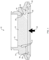
- Figure 1 shows sight glass 10 having an optically clear window 12 placed inside of metal frame 14, with frame slot 16 and frame groove 18 cut or formed into frame mating surface 20 which mirrors window mating surface 21.
- First surface 24 opposes second surface 13 of window 12.
- the window material can be chosen to suit specific application requirements, such as being able to withstand higher temperatures or pressures or to be FDA food safe.
- one non-limiting embodiment of sight glass 10 is for use in the manufacture of foods such as jam, granola bars, and other foods.
- Non-chipping polymer window 12 allows sight glass 10 to be used where glass windows are not acceptable.
- Frame mating surface 20 and window mating surface 21 secure window 12 within frame 14, allowing the window to withstand high pressures applied from a potential process or processes being observed through sight glass 10.
- Pressure 22 is applied against first surface 24 of window 12 which, in turn, presses against frame mating surface 20 and window mating surface 21 of sight glass 10.
- Window rim 26 overlaps frame slot 16 so that window 12 is pushed securely against frame 14 around the periphery of window 12.
- window 12 features a bulbous shaped region 28 which mirrors frame groove 18 helping to secure window 12 within frame 14, maximizing the pressure resistance of sight glass 10.
- Gasket 30 secures a portion of first surface 24 of window 12 to help maintain a secured and sealed position within frame 14.
- FIG. 2 A non-limiting application for sight glass 10 is depicted in figure 2 .
- Vessel 32 with interior surface 34 has a ferrule 36 that is constructed to mate with frame 14 and its gasket 30 to form sanitary connection 38, although a sanitary fitting is not shown for the sake of clarity.
- Window first surface 24 is the only part of sight glass 10 that is exposed to any processes occurring within vessel internal volume 39.
- FIG. 1 shows a non-claimed example with a sight glass 40 with generally conically-shaped window 42 and frame 44 constructed and arranged to fit window 42.
- gasket 46 is shown overlapping first surface 48 of window 42, although gasket 46 may not be necessary.
- Pressure 49 is applied from the process being observed against window first surface 48, further pressing window 42 against frame 44.
- the subject sight glass can be used in applications other than those that require a sanitary clamp-style fitting, as a frame and window can be applied without limitation of the fitting type.
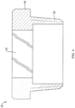
- figure 4 shows sight glass 50 having frame 54 with threaded plug-like extension 56.
- This embodiment shows sight glass 50 with window 52 mounted in frame 54, and threaded extension 56 that is sized and shaped to interface with a threaded port of some process vessel or the like.
- Extension 56 may or may not be intrinsic to the frame 54.
Landscapes
- Physics & Mathematics (AREA)
- General Physics & Mathematics (AREA)
- Optics & Photonics (AREA)
- Engineering & Computer Science (AREA)
- Chemical & Material Sciences (AREA)
- Fluid Mechanics (AREA)
- Health & Medical Sciences (AREA)
- Toxicology (AREA)
- Chemical Kinetics & Catalysis (AREA)
- Organic Chemistry (AREA)
- Combustion & Propulsion (AREA)
- Mechanical Engineering (AREA)
- General Engineering & Computer Science (AREA)
- Securing Of Glass Panes Or The Like (AREA)
- Glass Compositions (AREA)
Description
- The sight glass has its origins with steam processes and has been used on boilers and engines to observe water levels. Early sight glasses mostly consisted of simple glass tubes attached to a boiler.
- Modem day sight glasses, also known as sight windows, have found a place in process observation applications such as the pharmaceutical, food, beverage, and bio-gas industries, for example. Contemporary versions of sight glasses may be categorized as glass disc sight glasses or fused glass sight glasses. Glass disc sight glasses have glass discs that are held between metal frames and are secured with bolts and gaskets to create a seal. Fused glass sight glasses have glass that is fused or hermetically sealed to a metal frame and the seal does not necessarily require the use of bolts or gaskets. Fused sight glass processing often mechanically pre-stresses the glass by compressing it, and thereby increasing its strength.
- Sight glasses used in modern applications utilize various glass types. Soda lime and borosilicate are the two most common types used. Soda lime is the least expensive of the two and it provides optical clarity. Borosilicate, on the other hand, also tolerates high temperatures and is resistant to chemical corrosion and thermal shock, while maintaining its optical clarity. In addition, borosilicate has a lower coefficient of thermal expansion than many other glasses. Therefore it is able to withstand more significant pre-stressing, thereby increasing its strength more significantly.
- In the food industry, sight glasses with glass lenses are not always acceptable because glass can chip without complete failure and therefore can go unnoticed in applicable processes. One non-limiting application of a polymer sight glass window is in the manufacture of foods such as jams, granola bars, and other foods. There is a zero tolerance for glass in these applications, since glass chips can never be found in the final product. Therefore, there is a need for a safe, strong, and optically clear alternative to glass disc and fused glass sight glasses used in industry. Polymer windows will not chip and therefore are best for use in food manufacturing plants and other applications requiring the use of these devices. Sight glasses with polymer windows are known from
NZ 213 742 A FR 2 154 311 A1 - All examples and features mentioned below can be combined in any technically possible way.
- A sight glass meant for use in process observation in various industrial applications may have an optically clear polymer instead of glass. The optically clear polymer may be placed within a rigid frame, allowing a user to safely and clearly view processes of interest without disrupting the processes. The polymers used in the sight glass may withstand significant processing pressures which may be maximized through optimal geometric design of a lens frame in which it is installed. In one example, the geometry of the sight glass may be such that the polymer of the sight glass is the only material to come into contact with the process being viewed through the sight glass.
- The present disclosure includes a device that is similar to a fused glass-style sight glass that uses non-glass windows or optically clear polymers instead of glass. The internal geometry of the sight glass allows a polymer to withstand high pressures, while maintaining its integrity. The polymer can be selected to meet a wide variety of application requirements. Also, a frame mating surface may be generally conical, providing a surface to which a window mating surface mates with the frame mating surface, securing the window against the frame when pressure is applied against the window surface. The window may also have a bulbous, square, rectangular or otherwise shaped region that mates within a frame groove in the frame mating surface. Further, the frame could be constructed and arranged such that a part of it is exposed to an internal volume of a vessel to which the subject sight glass is mounted. In yet another embodiment, the frame could be made of non-metallic materials such as plastics that have sufficient mechanical properties, such as PEEK (Polyether ether ketone), for example.
- In one aspect, a sight glass window may be made from a polymer, or another non-glass material. In some non-limiting examples the window is optically clear. In other examples the window can act as a light filter, allowing infrared light to pass while blocking visible light, for example. Or the window may be made of a colored material in accordance with the preferences of the users. The window clarity and its light filtration properties may be chosen to meet the particular requirements of the process being viewed or the preferences of the users, depending upon the process and what the viewing is expected to accomplished through the window.
-
-
Figure 1 is a cross-sectional view of a sight glass with a non-glass window. -
Figure 2 is a cross-sectional view of an interface between a sight glass mounted to a process vessel. -
Figure 3 is a cross-sectional view of an example not falling within the scope of the claims of a sight glass with a non-glass, generally conically-shaped window within a likewise shaped frame. -
Figure 4 is a cross-sectional view of an alternate embodiment of a sight glass with a non-glass window. - Embodiments of the present invention relate to the use of polymer or other non-glass material, and unique geometry within a fused glass style sight glass.
Figure 1 showssight glass 10 having an opticallyclear window 12 placed inside ofmetal frame 14, withframe slot 16 andframe groove 18 cut or formed intoframe mating surface 20 which mirrorswindow mating surface 21.First surface 24 opposessecond surface 13 ofwindow 12. By using a polymer or another non-glass material instead of glass aswindow 12 ofsight glass 10, the window material can be chosen to suit specific application requirements, such as being able to withstand higher temperatures or pressures or to be FDA food safe. For the food industry, one non-limiting embodiment ofsight glass 10 is for use in the manufacture of foods such as jam, granola bars, and other foods. Non-chippingpolymer window 12 allowssight glass 10 to be used where glass windows are not acceptable. -
Frame mating surface 20 andwindow mating surface 21secure window 12 withinframe 14, allowing the window to withstand high pressures applied from a potential process or processes being observed throughsight glass 10.Pressure 22 is applied againstfirst surface 24 ofwindow 12 which, in turn, presses againstframe mating surface 20 andwindow mating surface 21 ofsight glass 10.Window rim 26overlaps frame slot 16 so thatwindow 12 is pushed securely againstframe 14 around the periphery ofwindow 12. Similarly, in this embodiment,window 12 features a bulbousshaped region 28 which mirrorsframe groove 18 helping to securewindow 12 withinframe 14, maximizing the pressure resistance ofsight glass 10.Gasket 30 secures a portion offirst surface 24 ofwindow 12 to help maintain a secured and sealed position withinframe 14. - A non-limiting application for
sight glass 10 is depicted infigure 2 .Vessel 32 withinterior surface 34 has aferrule 36 that is constructed to mate withframe 14 and itsgasket 30 to formsanitary connection 38, although a sanitary fitting is not shown for the sake of clarity. Windowfirst surface 24 is the only part ofsight glass 10 that is exposed to any processes occurring within vesselinternal volume 39. - The particular internal geometry/shape of
frame 14 infigure 1 is not necessary. The frame could take other shapes.Figure 3 shows a non-claimed example with asight glass 40 with generally conically-shaped window 42 andframe 44 constructed and arranged to fitwindow 42. In thisembodiment gasket 46 is shown overlappingfirst surface 48 ofwindow 42, althoughgasket 46 may not be necessary.Pressure 49 is applied from the process being observed against windowfirst surface 48, further pressingwindow 42 againstframe 44. - The subject sight glass can be used in applications other than those that require a sanitary clamp-style fitting, as a frame and window can be applied without limitation of the fitting type. For example,
figure 4 showssight glass 50 havingframe 54 with threaded plug-like extension 56. This embodiment showssight glass 50 withwindow 52 mounted inframe 54, and threadedextension 56 that is sized and shaped to interface with a threaded port of some process vessel or the like.Extension 56 may or may not be intrinsic to theframe 54. - A number of implementations have been described. Nevertheless, it will be understood that additional modifications may be made without departing from the scope of the inventive concepts described herein, and, accordingly, other embodiments are within the scope of the following claims.
Claims (11)
- A sight glass (10) for a vessel (32), comprising:a window (12) with a first surface (24), a mating surface (21), a second surface (13) opposing the first surface (24), and a window shaped region (28); anda frame (14) with a mating surface (20) and a frame groove (18), wherein the frame groove (18) is cut or formed in the frame mating surface (20);wherein the window (12) is a non-glass material;wherein the window (12) allows light to be transmitted through it;wherein the window shaped region (28) is a bulbous shaped region and wherein the window shaped region (28) is constructed and arranged to mate with the frame groove (18);wherein the frame (14) and the window (12) are constructed and arranged so that the window mating surface (21) and the frame mating surface (20) together create a secured configuration of the sight glass (10) so as to secure the window (12) within the frame (14), and so that the window first surface (24), in a state when the sight glass (10) is mounted to the vessel (32), is the only part of sight glass (10) that is exposed to any processes occurring within an internal volume (39) of the vessel (32).
- The sight glass (10) of claim 1 wherein the window (12) is a polymer.
- The sight glass (10) of claim 1 further comprising:a frame slot (16); anda window rim (26);wherein the frame slot (16) is cut or formed in the frame mating surface (20); andwherein the window rim (26) is constructed and arranged to mate with the frame slot (16).
- The sight glass (10) of claim 1 wherein the window (12) is made with a material that filters the transmission of infrared and visible light frequencies.
- The sight glass (10) of claim 1 wherein the window (12) is made of colored material.
- The sight glass (10) of claim 1 further comprising a gasket (30) wherein the gasket (30) secures a portion of the first surface (24) of the window (12) to help maintain a sealed configuration.
- The sight glass (10) of claim 1 wherein the frame mating surface (20) is generally conical and the window mating surface (21) is constructed and arranged to mate with the frame mating surface (20).
- The sight glass (10) of claim 1 wherein the frame (14) is made from a non-metallic material.
- The sight glass (10) of claim 1 further comprising a threaded extension (56) constructed and arranged for attachment to a mating threaded port to a vessel (32) in which a process may occur, wherein the threaded extension (56) is intrinsic to the frame (54).
- The sight glass (10) of claim 1 further comprising a threaded extension (56) constructed and arranged for attachment to a mating threaded port to a vessel (32) in which a process may occur, wherein the threaded extension (56) is extrinsic to the frame (54).
- The sight glass (10) of claim 1, wherein:the window (12) further comprises:
a rim (26); andthe frame (14) further comprises:a frame slot (16); anda gasket (30);wherein the frame slot (16) is cut or formed in the frame mating surface (20); andwherein the window rim (26) is constructed and arranged to mate with the frame slot (16); and wherein the gasket (30) secures a portion of the first surface (24) of the window (12) to help maintain a sealed configuration.
Applications Claiming Priority (2)
| Application Number | Priority Date | Filing Date | Title |
|---|---|---|---|
| US201662298172P | 2016-02-22 | 2016-02-22 | |
| PCT/US2017/018880 WO2017147154A1 (en) | 2016-02-22 | 2017-02-22 | Sight glass |
Publications (4)
| Publication Number | Publication Date |
|---|---|
| EP3419745A1 EP3419745A1 (en) | 2019-01-02 |
| EP3419745A4 EP3419745A4 (en) | 2019-10-09 |
| EP3419745B1 true EP3419745B1 (en) | 2024-08-28 |
| EP3419745C0 EP3419745C0 (en) | 2024-08-28 |
Family
ID=59686511
Family Applications (1)
| Application Number | Title | Priority Date | Filing Date |
|---|---|---|---|
| EP17757124.7A Active EP3419745B1 (en) | 2016-02-22 | 2017-02-22 | Sight glass |
Country Status (5)
| Country | Link |
|---|---|
| US (1) | US10914910B2 (en) |
| EP (1) | EP3419745B1 (en) |
| CN (1) | CN108712930B (en) |
| MX (1) | MX2018009320A (en) |
| WO (1) | WO2017147154A1 (en) |
Families Citing this family (6)
| Publication number | Priority date | Publication date | Assignee | Title |
|---|---|---|---|---|
| DE102018131800B4 (en) * | 2018-12-11 | 2022-03-03 | Auma Riester Gmbh & Co. Kg | Sight glass, housing, actuator and use of a sight glass |
| US11237338B2 (en) * | 2019-12-27 | 2022-02-01 | Lumentum Operations Llc | Optical element holder with a protruding feature to hold a chamfered optical element |
| JP2025516072A (en) * | 2022-05-09 | 2025-05-26 | エル.ジェイ.スター,インコーポレイテッド | Method for measuring the level at a container outlet and a rotatable sensor for carrying out said method - Patents.com |
| JP2024000252A (en) * | 2022-06-20 | 2024-01-05 | 株式会社ノーケン | sensor device |
| US12371370B2 (en) | 2023-01-12 | 2025-07-29 | Rayotek Scientific, Inc. | Method for manufacturing a fused metal sight window with a high flow temperature optical material |
| DE102024123254A1 (en) * | 2024-08-14 | 2026-02-19 | Auma Riester Gmbh & Co. Kg | Window for an actuator and an actuator with window |
Citations (4)
| Publication number | Priority date | Publication date | Assignee | Title |
|---|---|---|---|---|
| DE1263415B (en) * | 1963-08-16 | 1968-03-14 | Danfoss As | Process for the production of a sight glass, in particular for refrigeration systems, and a sight glass manufactured according to this |
| FR2154311A1 (en) * | 1971-09-28 | 1973-05-11 | Champeau Andre | |
| US5176029A (en) * | 1992-05-08 | 1993-01-05 | Maritrans Operating Partners L.P. | Ullage tube viewing device |
| WO2004081616A2 (en) * | 2003-03-11 | 2004-09-23 | Emerson Electric Co. | Low temperature sight glass manufacturing method |
Family Cites Families (21)
| Publication number | Priority date | Publication date | Assignee | Title |
|---|---|---|---|---|
| CH425368A (en) * | 1963-10-02 | 1966-11-30 | Tepro Technical Production Com | Observation window for machine housing or container |
| US3277713A (en) | 1965-02-23 | 1966-10-11 | Thomas R Demyon | Radiator sight gauge |
| US3977251A (en) | 1973-11-02 | 1976-08-31 | Meginnis Charles E | Sight glass assembly |
| US4162826A (en) * | 1978-03-20 | 1979-07-31 | Sybron Corporation | Sight glass assembly and method for its production |
| NZ213742A (en) * | 1985-10-08 | 1988-02-12 | Lincoln College | Inspection window |
| US4807474A (en) * | 1986-01-21 | 1989-02-28 | Pressure Products Company, Inc. | Sight glass assembly |
| CA2146464C (en) | 1990-04-19 | 1999-11-02 | Charles S. Argyle | Coolant corrosiveness indicator |
| DE4041816A1 (en) | 1990-12-24 | 1992-06-25 | Linnemann Friedrich | Sight glass fitting - has transparent disc with inclined coupling surface engaged by similar surface of counterposed flange |
| US5243929A (en) | 1991-09-24 | 1993-09-14 | Clark-Reliance Corporation | Tubular sanitary sight indicator |
| US5125269A (en) * | 1991-10-15 | 1992-06-30 | Regal Plastics Supply Of Omaha | Sight glass |
| US5974877A (en) * | 1996-05-01 | 1999-11-02 | Food Engineering Corporation | Sight window assembly and method of forming same |
| US6212989B1 (en) * | 1999-05-04 | 2001-04-10 | The United States Of America As Represented By The Secretary Of The Army | High pressure, high temperature window assembly and method of making the same |
| JP2001039387A (en) * | 1999-07-28 | 2001-02-13 | Nikon Corp | Pressure-resistant window |
| JP3733004B2 (en) * | 2000-06-19 | 2006-01-11 | アルプス電気株式会社 | Optical component and manufacturing method thereof |
| US6499439B1 (en) | 2001-06-15 | 2002-12-31 | Triad Metal Products Company | Modular stamped sight glass assembly |
| US6639745B1 (en) * | 2002-06-25 | 2003-10-28 | Kuo-Chung Cheng | Observation window of a hyperbaric chamber |
| JP4274830B2 (en) * | 2003-03-25 | 2009-06-10 | アルプス電気株式会社 | Method for manufacturing optical element with holder |
| CN2699255Y (en) * | 2004-04-23 | 2005-05-11 | 长丰泰塑胶五金制品(深圳)有限公司 | Stainless steel container water level observation window |
| EP2159619A1 (en) * | 2008-09-02 | 2010-03-03 | Siemens Aktiengesellschaft | A sight glass assembly |
| US8049978B1 (en) * | 2011-01-22 | 2011-11-01 | Cheng-Wei Su | Assembling structure for a magnifying glass |
| EP2735900A1 (en) * | 2012-11-21 | 2014-05-28 | High Q Laser GmbH | Support mechanism for an optical element and method for adjusting an optical element |
-
2017
- 2017-02-22 MX MX2018009320A patent/MX2018009320A/en unknown
- 2017-02-22 US US15/744,633 patent/US10914910B2/en active Active
- 2017-02-22 CN CN201780010493.9A patent/CN108712930B/en active Active
- 2017-02-22 WO PCT/US2017/018880 patent/WO2017147154A1/en not_active Ceased
- 2017-02-22 EP EP17757124.7A patent/EP3419745B1/en active Active
Patent Citations (4)
| Publication number | Priority date | Publication date | Assignee | Title |
|---|---|---|---|---|
| DE1263415B (en) * | 1963-08-16 | 1968-03-14 | Danfoss As | Process for the production of a sight glass, in particular for refrigeration systems, and a sight glass manufactured according to this |
| FR2154311A1 (en) * | 1971-09-28 | 1973-05-11 | Champeau Andre | |
| US5176029A (en) * | 1992-05-08 | 1993-01-05 | Maritrans Operating Partners L.P. | Ullage tube viewing device |
| WO2004081616A2 (en) * | 2003-03-11 | 2004-09-23 | Emerson Electric Co. | Low temperature sight glass manufacturing method |
Also Published As
| Publication number | Publication date |
|---|---|
| CA3012488A1 (en) | 2017-08-31 |
| WO2017147154A1 (en) | 2017-08-31 |
| US10914910B2 (en) | 2021-02-09 |
| EP3419745A4 (en) | 2019-10-09 |
| EP3419745C0 (en) | 2024-08-28 |
| CN108712930A (en) | 2018-10-26 |
| CN108712930B (en) | 2021-08-31 |
| MX2018009320A (en) | 2019-02-20 |
| EP3419745A1 (en) | 2019-01-02 |
| US20180203201A1 (en) | 2018-07-19 |
Similar Documents
| Publication | Publication Date | Title |
|---|---|---|
| US10914910B2 (en) | Sight glass | |
| US7990632B2 (en) | Optical element and stress athermalized hard contact mount | |
| CA3012488C (en) | Sight glass | |
| MX2021009100A (en) | Faãade glazing and insulating glazing unit. | |
| HK40001141A (en) | Sight glass | |
| HK40001141B (en) | Sight glass | |
| US9733110B2 (en) | Housing equipped with a viewing window | |
| US3977251A (en) | Sight glass assembly | |
| US4372652A (en) | Laminated gage glass assembly | |
| CA2394102C (en) | Gasket for a funnel for a coffee-making apparatus | |
| US12575047B2 (en) | Process for reversibly connecting a sensor to an inlet | |
| US20180021732A1 (en) | Membrane assembly with end cap device and related methods | |
| US10539239B2 (en) | Double seat valve for aseptic lines for product | |
| JP6987349B2 (en) | Lens unit and camera module | |
| US9500837B2 (en) | Bonding structure with CTE gradient for mounting an optical element in a frame | |
| WO2016112121A1 (en) | Fixture device for membrane assembly and related methods | |
| US10962771B2 (en) | Achromatic optical system with liquid lens | |
| JP5879592B2 (en) | column | |
| JP5174157B2 (en) | Measuring device window | |
| US3060738A (en) | Flowmeter | |
| JP2013208608A (en) | Membrane module | |
| CN221079036U (en) | High temperature resistant monitoring lens of auxiliary culinary art of oven | |
| CN219828574U (en) | Pipeline sight glass | |
| US9816915B2 (en) | Couplings for flame observation devices | |
| CN111399236B (en) | An industrial sight glass |
Legal Events
| Date | Code | Title | Description |
|---|---|---|---|
| STAA | Information on the status of an ep patent application or granted ep patent |
Free format text: STATUS: THE INTERNATIONAL PUBLICATION HAS BEEN MADE |
|
| PUAI | Public reference made under article 153(3) epc to a published international application that has entered the european phase |
Free format text: ORIGINAL CODE: 0009012 |
|
| STAA | Information on the status of an ep patent application or granted ep patent |
Free format text: STATUS: REQUEST FOR EXAMINATION WAS MADE |
|
| 17P | Request for examination filed |
Effective date: 20180813 |
|
| AK | Designated contracting states |
Kind code of ref document: A1 Designated state(s): AL AT BE BG CH CY CZ DE DK EE ES FI FR GB GR HR HU IE IS IT LI LT LU LV MC MK MT NL NO PL PT RO RS SE SI SK SM TR |
|
| AX | Request for extension of the european patent |
Extension state: BA ME |
|
| DAV | Request for validation of the european patent (deleted) | ||
| DAX | Request for extension of the european patent (deleted) | ||
| A4 | Supplementary search report drawn up and despatched |
Effective date: 20190909 |
|
| RIC1 | Information provided on ipc code assigned before grant |
Ipc: G01F 23/02 20060101ALI20190903BHEP Ipc: G02B 7/00 20060101ALI20190903BHEP Ipc: G01P 13/00 20060101ALI20190903BHEP Ipc: B01J 3/00 20060101AFI20190903BHEP |
|
| REG | Reference to a national code |
Ref country code: HK Ref legal event code: DE Ref document number: 40001141 Country of ref document: HK |
|
| STAA | Information on the status of an ep patent application or granted ep patent |
Free format text: STATUS: EXAMINATION IS IN PROGRESS |
|
| 17Q | First examination report despatched |
Effective date: 20201105 |
|
| GRAP | Despatch of communication of intention to grant a patent |
Free format text: ORIGINAL CODE: EPIDOSNIGR1 |
|
| STAA | Information on the status of an ep patent application or granted ep patent |
Free format text: STATUS: GRANT OF PATENT IS INTENDED |
|
| INTG | Intention to grant announced |
Effective date: 20240319 |
|
| GRAS | Grant fee paid |
Free format text: ORIGINAL CODE: EPIDOSNIGR3 |
|
| GRAA | (expected) grant |
Free format text: ORIGINAL CODE: 0009210 |
|
| STAA | Information on the status of an ep patent application or granted ep patent |
Free format text: STATUS: THE PATENT HAS BEEN GRANTED |
|
| AK | Designated contracting states |
Kind code of ref document: B1 Designated state(s): AL AT BE BG CH CY CZ DE DK EE ES FI FR GB GR HR HU IE IS IT LI LT LU LV MC MK MT NL NO PL PT RO RS SE SI SK SM TR |
|
| REG | Reference to a national code |
Ref country code: GB Ref legal event code: FG4D |
|
| REG | Reference to a national code |
Ref country code: CH Ref legal event code: EP |
|
| REG | Reference to a national code |
Ref country code: DE Ref legal event code: R096 Ref document number: 602017084471 Country of ref document: DE |
|
| REG | Reference to a national code |
Ref country code: IE Ref legal event code: FG4D |
|
| U01 | Request for unitary effect filed |
Effective date: 20240903 |
|
| U07 | Unitary effect registered |
Designated state(s): AT BE BG DE DK EE FI FR IT LT LU LV MT NL PT RO SE SI Effective date: 20240917 |
|
| PG25 | Lapsed in a contracting state [announced via postgrant information from national office to epo] |
Ref country code: NO Free format text: LAPSE BECAUSE OF FAILURE TO SUBMIT A TRANSLATION OF THE DESCRIPTION OR TO PAY THE FEE WITHIN THE PRESCRIBED TIME-LIMIT Effective date: 20241128 |
|
| PG25 | Lapsed in a contracting state [announced via postgrant information from national office to epo] |
Ref country code: PL Free format text: LAPSE BECAUSE OF FAILURE TO SUBMIT A TRANSLATION OF THE DESCRIPTION OR TO PAY THE FEE WITHIN THE PRESCRIBED TIME-LIMIT Effective date: 20240828 Ref country code: GR Free format text: LAPSE BECAUSE OF FAILURE TO SUBMIT A TRANSLATION OF THE DESCRIPTION OR TO PAY THE FEE WITHIN THE PRESCRIBED TIME-LIMIT Effective date: 20241129 |
|
| PG25 | Lapsed in a contracting state [announced via postgrant information from national office to epo] |
Ref country code: IS Free format text: LAPSE BECAUSE OF FAILURE TO SUBMIT A TRANSLATION OF THE DESCRIPTION OR TO PAY THE FEE WITHIN THE PRESCRIBED TIME-LIMIT Effective date: 20241228 |
|
| PG25 | Lapsed in a contracting state [announced via postgrant information from national office to epo] |
Ref country code: HR Free format text: LAPSE BECAUSE OF FAILURE TO SUBMIT A TRANSLATION OF THE DESCRIPTION OR TO PAY THE FEE WITHIN THE PRESCRIBED TIME-LIMIT Effective date: 20240828 |
|
| PG25 | Lapsed in a contracting state [announced via postgrant information from national office to epo] |
Ref country code: ES Free format text: LAPSE BECAUSE OF FAILURE TO SUBMIT A TRANSLATION OF THE DESCRIPTION OR TO PAY THE FEE WITHIN THE PRESCRIBED TIME-LIMIT Effective date: 20240828 Ref country code: RS Free format text: LAPSE BECAUSE OF FAILURE TO SUBMIT A TRANSLATION OF THE DESCRIPTION OR TO PAY THE FEE WITHIN THE PRESCRIBED TIME-LIMIT Effective date: 20241128 |
|
| PG25 | Lapsed in a contracting state [announced via postgrant information from national office to epo] |
Ref country code: RS Free format text: LAPSE BECAUSE OF FAILURE TO SUBMIT A TRANSLATION OF THE DESCRIPTION OR TO PAY THE FEE WITHIN THE PRESCRIBED TIME-LIMIT Effective date: 20241128 Ref country code: PL Free format text: LAPSE BECAUSE OF FAILURE TO SUBMIT A TRANSLATION OF THE DESCRIPTION OR TO PAY THE FEE WITHIN THE PRESCRIBED TIME-LIMIT Effective date: 20240828 Ref country code: NO Free format text: LAPSE BECAUSE OF FAILURE TO SUBMIT A TRANSLATION OF THE DESCRIPTION OR TO PAY THE FEE WITHIN THE PRESCRIBED TIME-LIMIT Effective date: 20241128 Ref country code: IS Free format text: LAPSE BECAUSE OF FAILURE TO SUBMIT A TRANSLATION OF THE DESCRIPTION OR TO PAY THE FEE WITHIN THE PRESCRIBED TIME-LIMIT Effective date: 20241228 Ref country code: HR Free format text: LAPSE BECAUSE OF FAILURE TO SUBMIT A TRANSLATION OF THE DESCRIPTION OR TO PAY THE FEE WITHIN THE PRESCRIBED TIME-LIMIT Effective date: 20240828 Ref country code: GR Free format text: LAPSE BECAUSE OF FAILURE TO SUBMIT A TRANSLATION OF THE DESCRIPTION OR TO PAY THE FEE WITHIN THE PRESCRIBED TIME-LIMIT Effective date: 20241129 Ref country code: ES Free format text: LAPSE BECAUSE OF FAILURE TO SUBMIT A TRANSLATION OF THE DESCRIPTION OR TO PAY THE FEE WITHIN THE PRESCRIBED TIME-LIMIT Effective date: 20240828 |
|
| U20 | Renewal fee for the european patent with unitary effect paid |
Year of fee payment: 9 Effective date: 20250211 |
|
| PG25 | Lapsed in a contracting state [announced via postgrant information from national office to epo] |
Ref country code: SM Free format text: LAPSE BECAUSE OF FAILURE TO SUBMIT A TRANSLATION OF THE DESCRIPTION OR TO PAY THE FEE WITHIN THE PRESCRIBED TIME-LIMIT Effective date: 20240828 |
|
| PG25 | Lapsed in a contracting state [announced via postgrant information from national office to epo] |
Ref country code: CZ Free format text: LAPSE BECAUSE OF FAILURE TO SUBMIT A TRANSLATION OF THE DESCRIPTION OR TO PAY THE FEE WITHIN THE PRESCRIBED TIME-LIMIT Effective date: 20240828 |
|
| PG25 | Lapsed in a contracting state [announced via postgrant information from national office to epo] |
Ref country code: SK Free format text: LAPSE BECAUSE OF FAILURE TO SUBMIT A TRANSLATION OF THE DESCRIPTION OR TO PAY THE FEE WITHIN THE PRESCRIBED TIME-LIMIT Effective date: 20240828 |
|
| PLBE | No opposition filed within time limit |
Free format text: ORIGINAL CODE: 0009261 |
|
| STAA | Information on the status of an ep patent application or granted ep patent |
Free format text: STATUS: NO OPPOSITION FILED WITHIN TIME LIMIT |
|
| 26N | No opposition filed |
Effective date: 20250530 |
|
| PG25 | Lapsed in a contracting state [announced via postgrant information from national office to epo] |
Ref country code: MC Free format text: LAPSE BECAUSE OF FAILURE TO SUBMIT A TRANSLATION OF THE DESCRIPTION OR TO PAY THE FEE WITHIN THE PRESCRIBED TIME-LIMIT Effective date: 20240828 |
|
| REG | Reference to a national code |
Ref country code: CH Ref legal event code: PL |
|
| PG25 | Lapsed in a contracting state [announced via postgrant information from national office to epo] |
Ref country code: CH Free format text: LAPSE BECAUSE OF NON-PAYMENT OF DUE FEES Effective date: 20250228 |
|
| GBPC | Gb: european patent ceased through non-payment of renewal fee |
Effective date: 20250222 |
|
| PG25 | Lapsed in a contracting state [announced via postgrant information from national office to epo] |
Ref country code: GB Free format text: LAPSE BECAUSE OF NON-PAYMENT OF DUE FEES Effective date: 20250222 |
|
| PG25 | Lapsed in a contracting state [announced via postgrant information from national office to epo] |
Ref country code: IE Free format text: LAPSE BECAUSE OF NON-PAYMENT OF DUE FEES Effective date: 20250222 |
|
| U20 | Renewal fee for the european patent with unitary effect paid |
Year of fee payment: 10 Effective date: 20260225 |