EP3419372B1 - Procédé de transmission de données dans un système de communication sans fil, procédé de planifier des ressources et dispositif d'utilisateur - Google Patents
Procédé de transmission de données dans un système de communication sans fil, procédé de planifier des ressources et dispositif d'utilisateur Download PDFInfo
- Publication number
- EP3419372B1 EP3419372B1 EP17753429.4A EP17753429A EP3419372B1 EP 3419372 B1 EP3419372 B1 EP 3419372B1 EP 17753429 A EP17753429 A EP 17753429A EP 3419372 B1 EP3419372 B1 EP 3419372B1
- Authority
- EP
- European Patent Office
- Prior art keywords
- data
- preamble
- network node
- request message
- random access
- Prior art date
- Legal status (The legal status is an assumption and is not a legal conclusion. Google has not performed a legal analysis and makes no representation as to the accuracy of the status listed.)
- Active
Links
- 238000000034 method Methods 0.000 title claims description 214
- 230000005540 biological transmission Effects 0.000 title claims description 134
- 238000004891 communication Methods 0.000 title claims description 47
- 230000004044 response Effects 0.000 claims description 202
- 238000013468 resource allocation Methods 0.000 claims description 147
- 238000012795 verification Methods 0.000 claims description 62
- 230000006870 function Effects 0.000 description 59
- 238000007726 management method Methods 0.000 description 28
- 238000010586 diagram Methods 0.000 description 25
- 230000008569 process Effects 0.000 description 24
- 230000011664 signaling Effects 0.000 description 10
- 125000004122 cyclic group Chemical group 0.000 description 9
- 230000000694 effects Effects 0.000 description 9
- 238000005516 engineering process Methods 0.000 description 8
- 230000015654 memory Effects 0.000 description 8
- 238000010295 mobile communication Methods 0.000 description 7
- CSRZQMIRAZTJOY-UHFFFAOYSA-N trimethylsilyl iodide Substances C[Si](C)(C)I CSRZQMIRAZTJOY-UHFFFAOYSA-N 0.000 description 6
- 230000009471 action Effects 0.000 description 5
- 239000000872 buffer Substances 0.000 description 5
- 238000012986 modification Methods 0.000 description 5
- 230000004048 modification Effects 0.000 description 5
- 238000012545 processing Methods 0.000 description 5
- 238000012546 transfer Methods 0.000 description 5
- 208000037918 transfusion-transmitted disease Diseases 0.000 description 5
- 230000002776 aggregation Effects 0.000 description 4
- 238000004220 aggregation Methods 0.000 description 4
- 230000007774 longterm Effects 0.000 description 4
- 238000005259 measurement Methods 0.000 description 4
- 101000741965 Homo sapiens Inactive tyrosine-protein kinase PRAG1 Proteins 0.000 description 3
- 102100038659 Inactive tyrosine-protein kinase PRAG1 Human genes 0.000 description 3
- 230000001960 triggered effect Effects 0.000 description 3
- 230000004308 accommodation Effects 0.000 description 2
- 239000000969 carrier Substances 0.000 description 2
- 230000001413 cellular effect Effects 0.000 description 2
- 230000006835 compression Effects 0.000 description 2
- 238000007906 compression Methods 0.000 description 2
- 238000001514 detection method Methods 0.000 description 2
- 239000002360 explosive Substances 0.000 description 2
- 238000001914 filtration Methods 0.000 description 2
- 238000013507 mapping Methods 0.000 description 2
- 230000007246 mechanism Effects 0.000 description 2
- 230000007704 transition Effects 0.000 description 2
- ATJFFYVFTNAWJD-UHFFFAOYSA-N Tin Chemical compound [Sn] ATJFFYVFTNAWJD-UHFFFAOYSA-N 0.000 description 1
- 230000003321 amplification Effects 0.000 description 1
- 238000004458 analytical method Methods 0.000 description 1
- 230000015572 biosynthetic process Effects 0.000 description 1
- 230000008859 change Effects 0.000 description 1
- 238000012937 correction Methods 0.000 description 1
- 238000013500 data storage Methods 0.000 description 1
- 230000001934 delay Effects 0.000 description 1
- 230000001419 dependent effect Effects 0.000 description 1
- 238000013461 design Methods 0.000 description 1
- 230000009977 dual effect Effects 0.000 description 1
- VJYFKVYYMZPMAB-UHFFFAOYSA-N ethoprophos Chemical compound CCCSP(=O)(OCC)SCCC VJYFKVYYMZPMAB-UHFFFAOYSA-N 0.000 description 1
- 230000003993 interaction Effects 0.000 description 1
- 238000012423 maintenance Methods 0.000 description 1
- 230000014759 maintenance of location Effects 0.000 description 1
- 239000011159 matrix material Substances 0.000 description 1
- 238000012544 monitoring process Methods 0.000 description 1
- 230000006855 networking Effects 0.000 description 1
- 238000003199 nucleic acid amplification method Methods 0.000 description 1
- 230000003287 optical effect Effects 0.000 description 1
- 230000011218 segmentation Effects 0.000 description 1
- 238000000926 separation method Methods 0.000 description 1
- 230000008054 signal transmission Effects 0.000 description 1
- 238000001228 spectrum Methods 0.000 description 1
- 230000003068 static effect Effects 0.000 description 1
- 230000005641 tunneling Effects 0.000 description 1
Images


Classifications
-
- H—ELECTRICITY
- H04—ELECTRIC COMMUNICATION TECHNIQUE
- H04W—WIRELESS COMMUNICATION NETWORKS
- H04W74/00—Wireless channel access, e.g. scheduled or random access
- H04W74/08—Non-scheduled or contention based access, e.g. random access, ALOHA, CSMA [Carrier Sense Multiple Access]
- H04W74/0833—Non-scheduled or contention based access, e.g. random access, ALOHA, CSMA [Carrier Sense Multiple Access] using a random access procedure
-
- H—ELECTRICITY
- H04—ELECTRIC COMMUNICATION TECHNIQUE
- H04W—WIRELESS COMMUNICATION NETWORKS
- H04W72/00—Local resource management
- H04W72/12—Wireless traffic scheduling
-
- H—ELECTRICITY
- H04—ELECTRIC COMMUNICATION TECHNIQUE
- H04W—WIRELESS COMMUNICATION NETWORKS
- H04W68/00—User notification, e.g. alerting and paging, for incoming communication, change of service or the like
- H04W68/005—Transmission of information for alerting of incoming communication
-
- H—ELECTRICITY
- H04—ELECTRIC COMMUNICATION TECHNIQUE
- H04W—WIRELESS COMMUNICATION NETWORKS
- H04W72/00—Local resource management
- H04W72/20—Control channels or signalling for resource management
- H04W72/23—Control channels or signalling for resource management in the downlink direction of a wireless link, i.e. towards a terminal
Definitions
- the present invention relates to a method for transmitting data by a user equipment in a wireless communication system, to a method for scheduling resources by a network node for data transmission in a wireless communication system and to a corresponding user equipment.
- Mobile communication systems have emerged to provide a voice service while guaranteeing mobility of a user.
- the mobile communication system of today has been expanded to support data services in addition to the voice service. Due to the explosive increase of today's traffic, resources are running short; more and more users are demanding higher speed services; and a more advanced mobile communication system is required accordingly.
- Key requirements for a next-generation mobile communication system include accommodation of explosive data traffic, significant increase of transmission rate per user, accommodation of a significantly increased number of connected devices, very low end-to-end latency, and high energy efficiency.
- various technologies such as dual connectivity, massive Multiple Input Multiple Output (MIMO), in-band full duplex, Non-Orthogonal Multiple Access (NOMA), super wideband, and device networking are being studied.
- An object of the present invention is to provide a resource scheduling method and apparatus for transmitting and receiving data.
- an object of the present invention is to provide a method and apparatus for transmitting and receiving data through the resource scheduling of a network node in the state in which a connection between a user equipment and a network node has not been established.
- an object of the present invention is to provide a method and apparatus for a network node to schedule resources based on information related to data to be transmitted, which has been transmitted by a user equipment.
- an object of the present invention is to provide a method and apparatus for a network node to receive preambles classified based on the direction and size of transmitted and received data from a user equipment and to schedule resources.
- an embodiment of the present invention provides a method and a device for transmitting a message for requesting a random access including information of data to be transmitted together with a preamble in a random access procedure with a network node to be allocated resources from a base station by a terminal.
- the present invention provides a method and a device for transmitting data by a device in a wireless communication system.
- a method for transmitting data which includes: transmitting to a network node a first preamble and a first request message for requesting random access, the first request message including at least one of purpose information indicating a purpose of transmitting the first request message, count information indicating the number of times of trying the random access, size information of first data, or a first identifier for contention resolution; as a response to the first request message, receiving a first response message including a second identifier for indicating whether the first request message is decoded and contention resolution and an index of a second preamble successfully received by the network node; and while the connection with the network node is not established, transmitting the first data to the network node in accordance with the index of the second preamble and the second identifier.
- the first request message when the first data is uplink data, the first request message further includes characteristic information of the first data.
- the first request message when the first data is verification information of UE for receiving downlink data, the first request message further includes characteristic information of the downlink data.
- the method further includes selecting the first preamble in a preamble set, and the preamble set is one of multiple preamble sets determined according to a size and a transmission direction of data.
- the response message further includes a radio network identifier of a device allocated by the network node.
- the first response message when the index of the first preamble and the index of the second preamble are the same as each other and a value of the second identifier indicates decoding success of the first request message, the first response message includes resource allocation information for transmitting the first data and the first data is transmitted based on the resource allocation information.
- the method further includes: when the index of the first preamble and the index of the second preamble are the same as each other and the value of the second identifier indicates decoding failure of the first request message, transmitting a second request message for requesting resource allocation for transmitting the first data to the network node; and receiving a second response message including resource allocation information for transmitting the first data, and the first data is transmitted based on the resource allocation information.
- the method further includes when the index of the first preamble and the index of the second preamble are not the same as each other, transmitting to the network node a third preamble and a second request message for requesting the random access.
- the method further includes: when the first data is UE verification data for transmitting downlink data, receiving a paging message from the network node; and receiving the downlink data from the network node, and the paging message further includes a UE identifier indicating device receiving the downlink data and quality information indicating a quality of the downlink data.
- the present invention provides a method including: receiving from user equipments (UEs) one or more first preambles and a first request message for requesting random access, each of the one or more first request messages including at least one of purpose information indicating a purpose of transmitting the first request message, count information indicating the number of times of trying the random access, size information of data to be transmitted by the UE, characteristic information of uplink or downlink data, or a first identifier for contention resolution; allocating a resource to at least one UE among the UE based on at least one of the purpose information, the count information, the size information, or the characteristic information; transmitting one or more first response messages as a response to the one or more first request messages; and receiving the data from the at least one UE while not being connected with the at least one node.
- UEs user equipments
- each of the one or more first preambles is selected in one preamble set among multiple preamble sets determined according to a size and a transmission direction of data to be transmitted.
- each of the one or more response messages includes a second identifier indicating contention resolution and indicating whether to decode each of the one or more first request messages and a preamble index indicating a preamble successfully received by the network node among the one or more first preambles.
- the method further includes: receiving a second request message for requesting resource allocation for transmitting the data from one or more UE which is not allocated the resource among the UE; and transmitting a second response message including resource allocation information indicating a resource allocated for transmitting the data to the one or more UE as a response to the second request message.
- the method further includes when the data is UE verification data for transmitting downlink data, transmitting a paging message from the UE, and the paging message further includes a UE identifier indicating UE to which the downlink data is transmitted and quality information indicating a quality of the downlink data.
- the present invention provides UE including: a communication unit transmitting and receiving a radio signal to and from the outside; and a processor functionally coupled with the communication unit, and the processor transmits to a network node a first preamble and a first request message for requesting random connection, the first request message including at least one of purpose information indicating a purpose of transmitting the first request message, count information indicating the number of times of trying the random access, size information of first data, or a first identifier for contention resolution, as a response to the first request message, receives a first response message including a second identifier for indicating whether the first request message is decoded and contention resolution and an index of a second preamble successfully received by the network node, and while the connection with the network node is not established, transmits the first data to the network node in accordance with the index of the second preamble and the second identifier.
- the present invention has an effect in that latency of data transmission and reception can be reduced because a UE transmits and receives data without establishing a connection with a network node.
- the present invention has an effect in that data can be transmitted and received even without establishing a connection with a network node because resources allocated by a network node are received by transmitting a preamble for random access and a request message to request random access together.
- the present invention has an effect in that a UE can receive resources allocated based on the quality and requirements of data because the UE receives resources allocated by an eNB based on information of data to be transmitted by the UE.
- the present invention has an effect in that a network node can differentially allocate resources for each UE based on the size of data, required latency, a transmission object and a transmission direction by scheduling resources based on information transmitted by a UE.
- a base station has a meaning of a user equipment node of a network, which directly communicates with a user equipment.
- a specific operation described as being performed by the base station may also be performed by an upper node of the base station. Namely, it is apparent that, in a network including a plurality of network nodes including a base station, various operations performed for communication with a user equipment may be performed by the base station, or network nodes other than the base station.
- BS base station
- eNB evolved-NodeB
- BTS base transceiver system
- AP access point
- the term 'user equipment may be fixed or mobile, and may be replaced with the term 'user equipment (UE)', 'mobile station (MS)', 'user user equipment (UT)', 'mobile subscriber station (MSS)', 'subscriber station (SS)', 'advanced mobile station (AMS)', 'wireless user equipment (WT)', 'machine-type communication (MTC) device', 'machine-to-machine (M2M) device', 'device-to-device (D2D) device', and the like.
- UE user equipment
- MS mobile station
- UT 'mobile subscriber station
- SS 'subscriber station
- AMS 'advanced mobile station
- WT wireless user equipment
- MTC machine-type communication
- M2M machine-to-machine
- D2D device'
- the downlink means communication from a base station to a user equipment
- the uplink means communication from a user equipment to a base station.
- a transmitter may be part of a base station
- a receiver may be part of a user equipment.
- a transmitter may be part of a user equipment, and the receiver may be part of a base station.
- CDMA code division multiple access
- FDMA frequency division multiple access
- TDMA time division multiple access
- OFDMA orthogonal frequency division multiple access
- SC-FDMA single carrier frequency division multiple access
- NOMA non-orthogonal multiple access
- CDMA may be implemented as a radio technology, such as universal terrestrial radio access (UTRA) or CDMA2000.
- TDMA may be implemented as a radio technology, such as global system for mobile communications (GSM)/general packet radio service (GPRS)/enhanced data rates for GSM evolution (EDGE).
- GSM global system for mobile communications
- GPRS general packet radio service
- EDGE enhanced data rates for GSM evolution
- OFDMA may be implemented as a radio technology, such as IEEE 802.11 (Wi-Fi), IEEE 802.16 (WiMAX), IEEE 802-20, or evolved UTRA (E-UTRA).
- UTRA is part of a universal mobile telecommunications system (UMTS).
- 3rd generation partnership project (3GPP) long term evolution (LTE) is part of an evolved UMTS (E-UMTS) using E-UTRA, and adopts OFDMA in the downlink and adopts SC-FDMA in the uplink.
- LTE-advanced (A) is the evolution of 3GPP LTE.
- Embodiments of the present invention may be supported by at least one standard document which is described in IEEE 802, 3GPP and 3GPP2, which are wireless access systems. That is, among the embodiments of the present invention, steps or parts that are not described for disclosing the technical concept of the present invention apparently may be supported by the documents. In addition, all terms disclosed in this document may be described by the standard document.
- the present invention is described mainly for 3GPP LTE/LTE-A, but the technical features of the present invention are not limited thereto, but may also be applied to 5G system.
- EPS This is an abbreviation of Evolved Packet System, and means a core network that supports Long Term Evolution (LTE) network. This is a network in the form evolved from UMTS.
- LTE Long Term Evolution
- PDN Public Data Network
- APN Access Point Name
- This is a name of an access point managed in a network, and provided to a UE. That is, this indicates a name (a character string) of the PDN. Based on the name of an access point, the corresponding PDN for transmitting and receiving data is determined.
- TEID (Tunnel Endpoint Identifier): This is an End point ID of a tunnel configured between nodes in a network, and configured in each section as a unit of bearer of each UE.
- MME Mobility Management Entity
- This is an abbreviation of Mobility Management Entity, and plays the role of controlling each entity in the EPS in order to provide a session and mobility for a UE.
- a session is a passage for transmitting data, and the unit may be a unit of PDN, Bearer, IP flow, and so on.
- a difference of each unit may be distinguished by a target network entire unit (a unit of APN or PDN), a unit distinguished by QoS therein (a unit of Bearer) and a unit of destination IP address as defined in 3GPP.
- a target network entire unit a unit of APN or PDN
- QoS therein a unit of Bearer
- a unit of destination IP address as defined in 3GPP.
- EPS Bearer A logical path generated between a UE and a gateway through which various types of traffics are transmitted and received.
- Default EPS Bear This is a logical path for transmitting and receiving data which is generated basically when a UE accesses to a network, and may be maintained until the UE is detached from the network.
- Dedicated EPS Bearer A logical path generated for being provided with a service additionally after the Default EPS Bear is generated, if it is required.
- IP flow Various types of traffics transmitted and received through a logical path between a UE and a gateway.
- Service Data Flow IP flow of a user traffic or combination of a plurality of IP flows which is classified according to a service type.
- PDN connection This represents an association (connection) between a UE represented by an IP address and the PDN represented by the APN.
- UE Context State information of a UE used for managing the UE in a network, that is, state information including UE ID, mobility (current location, etc.), an attribute of a session (QoS, priority, etc.)
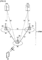
- FIG. 1 is a view illustrating an Evolved Packet System which is associated with the Long Term Evolution (LTE) system to which the present invention can be applied.
- LTE Long Term Evolution
- the LTE system aims to provide seamless Internet Protocol (IP) connectivity between a user equipment (UE) 10) and a pack data network (PDN), without any disruption to the end user's application during mobility. While the LTE system encompasses the evolution of the radio access through an E-UTRAN (Evolved Universal Terrestrial Radio Access Network) which defines a radio protocol architecture between a user equipment and a base station 20, it is accompanied by an evolution of the non-radio aspects under the term 'System Architecture Evolution' (SAE) which includes an Evolved Packet Core (EPC) network.
- SAE System Architecture Evolution'
- the LTE and SAE comprise the Evolved Packet System (EPS).
- EPS Evolved Packet System
- the EPS uses the concept of EPS bearers to route IP traffic from a gateway in the PDN to the UE.
- a bearer is an IP packet flow with a specific Quality of Service (QoS) between the gateway and the UE.
- QoS Quality of Service
- the E-UTRAN and EPC together set up and release the bearers as required by applications.
- the EPC which is also referred to as the core network (CN), controls the UE and manages establishment of the bearers.
- CN core network
- the node (logical or physical) of the EPC in the SAE includes a Mobility Management Entity (MME) 30, a PDN gateway (PDN-GW or P-GW) 50, a Serving Gateway (S-GW) 40, a Policy and Charging Rules Function (PCRF) 60, a Home subscriber Server (HSS) 70, etc.
- MME Mobility Management Entity
- PDN-GW or P-GW PDN gateway
- S-GW Serving Gateway
- PCRF Policy and Charging Rules Function
- HSS Home subscriber Server
- the MME 30 is the control node which processes the signaling between the UE and the CN.
- the protocols running between the UE and the CN are known as the Non-Access Stratum (NAS) protocols.
- NAS Non-Access Stratum
- Examples of functions supported by the MME 30 includes functions related to bearer management, which includes the establishment, maintenance and release of the bearers and is handled by the session management layer in the NAS protocol, and functions related to connection management, which includes the establishment of the connection and security between the network and UE, and is handled by the connection or mobility management layer in the NAS protocol layer.
- the MME 30 corresponds to an entity in which a function necessary to process authentication of the UE and context information is implemented, where the MME 30 is described as one embodiment of the entity. Therefore, other devices in addition to the MME 30 can also carry out the corresponding function.
- the S-GW 40 serves as the local mobility anchor for the data bearers when the UE moves between eNodeBs. All user IP packets are transferred through the S-GW 40.
- the S-GW 40 also retains information about the bearers when the UE is in idle state (known as ECM-IDLE) and temporarily buffers downlink data while the MME initiates paging of the UE to re-establish the bearers. Further, it also serves as the mobility anchor for inter-working with other 3GPP technologies such as GPRS (General Packet Radio Service) and UMTS (Universal Mobile Telecommunications System).
- GPRS General Packet Radio Service
- UMTS Universal Mobile Telecommunications System
- the S-GW 40 corresponds to an entity in which a function necessary for processing authentication of the UE and context information is implemented, where the S-GW 40 is described as one embodiment of the entity. Therefore, other devices in addition to the S-GW 40 can also carry out the corresponding function.
- the P-GW 50 serves to perform IP address allocation for the UE, as well as QoS enforcement and flow-based charging according to rules from the PCRF 60.
- the P-GW 50 performs QoS enforcement for Guaranteed Bit Rate (GBR) bearers. It also serves as the mobility anchor for inter-working with non-3GPP technologies such as CDMA2000 and WiMAX networks.
- GLR Guaranteed Bit Rate
- the P-GW 50 corresponds to an entity in which a function necessary for processing routing/forwarding of user data is implemented, where the P-GW 50 is described as one embodiment of the entity. Therefore, other devices in addition to the P-GW 50 can also carry out the corresponding function.
- the PCRF 60 performs policy control decision-making and performs flow-based charging.
- the HSS 70 is also called a home location register (HLR), and includes an EPS-subscribed QoS profile and SAE subscription data including access control information for roaming. Furthermore, the HSS also includes information about a PDN accessed by a user. Such information may be maintained in an access point name (APN) form.
- the APN is a domain name system (DNS)-based label, and is an identity scheme that describes an access point for a PDN or a PDN address indicative of a subscribed IP address.
- DNS domain name system
- various interfaces such as S1-U, S1-MME, S5/S8, S11, S6a, Gx, Rx and SG, may be defined between EPS network elements.
- the mobility management (MM) is a procedure for reducing overhead on the E-UTRAN and processing in a UE.
- the MME may maintain UE context and information related to a configured bearer during an Idle interval.
- a UE may notify a network of a new location whenever it deviates from a current tracking area (TA) so that the network may contact the UE in the ECM-IDLE state.
- TA current tracking area
- Such a procedure may be called “Tracking Area Update.”
- This procedure may be called “Routing Area Update” in a universal terrestrial radio access network (UTRAN) or GSM EDGE radio access network (GERAN) system.
- UTRAN universal terrestrial radio access network
- GERAN GSM EDGE radio access network
- the MME transmits a paging message to all of eNodeB on a tracking area (TA) with which the UE has been registered.
- TA tracking area
- the base station starts paging for the UE on a radio interface.
- the base station performs a procedure that enables the state of the UE to switch to the ECM-CONNECTED state.
- Such a procedure may be called a "Service Request Procedure.”
- the MME performs the re-establishment of the radio bearers and a function of updating UE context on the base station.
- a mobility management (MM) backoff timer may be additionally used.
- the UE may transmit tracking area update (TAU) in order to update the TA.
- TAU tracking area update
- the MME may reject a TAU request due to core network congestion.
- the MME may provide a time value related to the MM backoff timer.
- the UE may activate the MM backoff timer.
- FIG. 2 illustrates a wireless communication system to which the present invention is applied.
- the wireless communication system may also be called an Evolved-UMTS Terrestrial Radio Access Network (E-UTRAN) or a Long Term Evolution (LTE)/LTE-A system.
- E-UTRAN Evolved-UMTS Terrestrial Radio Access Network
- LTE Long Term Evolution
- LTE-A Long Term Evolution
- the E-UTRAN includes a base station (BS) 20 that provides a control plane and a user plane to user equipment (UE) 10.
- BS base station
- UE user equipment
- the base stations 20 may be interconnected via an X2 interface.
- the base station 20 is connected to an evolved packet core (EPC) through an S1 interface, more particularly, to a mobility management entity (MME) through S1-MME and a serving gateway (S-GW) through S1-U.
- EPC evolved packet core
- MME mobility management entity
- S-GW serving gateway
- the EPC is constituted by of the MME, the S-GW, and a packet data network-gateway (P-GW).
- the MME has access information of the terminal or information on a capability of the terminal and the information is mainly used for managing the mobility of the UE.
- the S-GW is a gateway having the E-UTRAN as an end point and the P-GW is a gateway having the PDN as the end point.
- Layers of a radio interface protocol between the UE and the network may be classified into L1 (first layer), L2 (second layer), and L3 (third layer) based on three lower layers of an open system interconnection (OSI) reference model which is widely known in a communication system and among them, a physical layer which belongs to the first layer provides an information transfer service using a physical channel and a radio resource control (RRC) layer positioned in the third layer serves to control a radio resource between the UE and the network. To this end, the RRC layer exchanges an RRC message between the UE and the BS.
- L1 first layer
- L2 second layer
- L3 third layer
- OSI open system interconnection
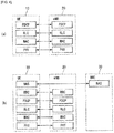
- FIG. 3 is a block diagram illustrating an example of a functional split between an E-UTRAN and an EPC to which the present invention may be applied.
- a hatched block represents a radio protocol layer
- an empty block represents a functional entity of the control plane.
- the BS performs the following functions: (1) Radio resource management (RRM) function such as radio bearer control, radio admission control, connection mobility control, and dynamic resource allocation to the UE, (2) Internet Protocol (IP) header compression and encryption of user data streams, (3) routing of user plane data to the S-GW, (4) scheduling and transmission of a paging message, (5) scheduling and transmission of broadcast information, and (6) measurement and measurement reporting setup for mobility and scheduling.
- RRM Radio resource management
- IP Internet Protocol
- the MME performs the following functions: (1) Distribution of the paging message to the BSs, (2) security control, (3) idle state mobility control, (4) SAE bearer control, and (5) non-access stratum (NAS) signaling ciphering and integrity protection.
- NAS non-access stratum
- the S-GW performs the following functions: (1) Termination of a user plane packet for paging and (2) user plane switching for supporting UE mobility
- FIG. 4 is a diagram illustrating one example of a radio protocol architecture to which a technical feature of the present invention may be applied.
- FIG. 4(a) illustrates an example of a radio protocol architecture for a user plane
- FIG. 4(b) is a block diagram illustrating an example of the radio protocol architecture for a control plane.
- the user plane is a protocol stack for transmitting user data and the control plane is a protocol stack for transmitting a control signal.
- the physical layer provides the information transfer service to an upper layer using the physical channel.
- the physical layer is connected to a medium access control (MAC) layer which is the upper layer through a transport channel. Data moves between the MAC layer and the physical layer through the transport channel.
- the transport channel is classified according to how the data is transmitted through a radio interface and what feature the data is transmitted.
- the physical channel may be modulated by an orthogonal frequency division multiplexing (OFDM) scheme and uses a time and a frequency as the radio resources.
- OFDM orthogonal frequency division multiplexing
- the function of the MAC layer includes mapping between a logical channel and a transmission channel and multiplexing/demultiplexing (a meaning of '/' includes both concepts of 'or' and 'and') to the transport block provided to the physical channel on the transport channel of an MAC service data unit (SDU) which belongs to the logical channel.
- the MAC layer provides a service to a radio link control (RLC) layer through the logical channel.
- RLC radio link control
- the function of the RLC layer includes concatenation, segmentation, and reassembly of the RLC SDUs.
- the RLC layer provides three operating modes of a transparent mode (TM), an unacknowledged mode (UM), and an acknowledged mode (AM).
- TM transparent mode
- UM unacknowledged mode
- AM acknowledged mode
- the AM RLC provides error correction through an automatic repeat request (ARQ).
- the radio resource control (RRC) layer is defined only in the control plane.
- the RRC layer serves to control the logical, transport, and physical channels in connection with configuration, re-configuration and release of the radio bearers.
- the RB means a logical path provided by the first layer (PHY layer) and the second layer (MAC layer, RLC layer, or PDCP layer) for data transmission between the UE and the network.
- the function of the packet data convergence protocol (PDCP) layer in the user plane includes transmission of the user data, header compression, and ciphering.
- the function of the packet data convergence protocol (PDCP) layer in the control plane includes transmission of the control plane data and ciphering/integrity protection.
- Configuring the RB means a process of defining the characteristics of the radio protocol layer and the channel to provide a specific service and configuring each specific parameter and operation method.
- the RB may be divided into a signaling RB (SRB)) and a data RB (DRB) again.
- SRB is used as a path for transmitting the RRC message in the control plane
- DRB is used as a path for transmitting the user data in the user plane.
- the UE When an RRC connection is established between the RRC layer of the UE and the RRC layer of the E-UTRAN, the UE is in an RRC connected state and if not, the UE is in an RRC idle state.
- a downlink transmission channel for transmitting data from the network to the UE includes a broadcast channel (BCH) for transmitting system information and a downlink shared channel (SCH) for transmitting user traffic and a control message.
- the traffic or control message of a downlink multicast or broadcast service may be transmitted through a downlink SCH or may be transmitted via a separate downlink multicast channel (MCH).
- an uplink transmission channel for transmitting data from the network to the UE includes a random access channel (RACH) for transmitting an initial control message and an uplink shared channel (SCH) for transmitting other user traffic or control messages.
- RACH random access channel
- Examples of a logical channel existing at an upper layer of the transport channel and mapped to the transport channel include a broadcast control channel (BCCH), a paging control channel (PCCH), a common control channel (CCCH), a multicast control channel (MCCH), a multicast traffic Channel (MTCH), and the like.
- BCCH broadcast control channel
- PCCH paging control channel
- CCCH common control channel
- MCCH multicast control channel
- MTCH multicast traffic Channel
- the physical channel is constituted by several OFDM symbols in a time domain and several sub-carriers in a frequency domain.
- One sub-frame is composed of the plurality of OFDM symbols in the time domain.
- a resource block as a resource allocation unit is constituted by the plurality of OFDM symbols and a plurality of sub-carriers.
- each subframe may use specific subcarriers of specific OFDM symbols (e.g., first OFDM symbol) of the corresponding subframe for a physical downlink control channel (PDCCH), i.e., an L1/L2 control channel.
- a transmission time interval (TTI) is a time unit of subframe transmission.
- FIG. 5 is a diagram for describing physical channels used in a 3GPP LTE/LTE-A system and a general signal transmitting method using the same to which the present invention may be applied.
- step S5010 the UE that is powered on again while being powered off or enters a new cell performs an initial cell search operation such as synchronizing with the BS.
- the UE receives a primary synchronization channel (P-SCH) and a secondary synchronization channel (S-SCH) from the BS and synchronizes with the BS and acquires information such as a cell ID or the like.
- P-SCH primary synchronization channel
- S-SCH secondary synchronization channel
- the UE may receive a physical broadcast channel (PBCH) signal from the BS and obtain the in-cell broadcast information. Meanwhile, the UE receives a downlink reference signal (DL RS) in an initial cell search step to check a downlink channel status.
- PBCH physical broadcast channel
- DL RS downlink reference signal
- the UE Upon completion of the initial cell search, the UE receives the PDCCH and the PDSCH according to PDCCH information in step S5020 to obtain more specific system information.
- the UE may perform a random access procedure such as steps S5030 to S5060 to complete the access to the BS.
- the UE may transmit the preamble through a physical random access channel (PRACH) (S5030) and receive a response message to the preamble through the PDCCH and the PDSCH corresponding thereto (S5040).
- PRACH physical random access channel
- the UE may perform a contention resolution procedure such as transmission of an additional PRACH signal (S5050) and reception of a PDCCH signal and a PDSCH signal corresponding thereto (S506).
- the UE that performs the above procedure may then receive the PDCCH signal and/or PDSCH signal (S5070) and/or a physical uplink shared channel (PUSCH) signals and/or a physical uplink control channel (PUCCH) signal (S5080) as a general uplink/downlink signal transmission procedure.
- PUSCH physical uplink shared channel
- PUCCH physical uplink control channel
- the UCI includes HARQ-ACK/NACK, a scheduling request (SR), a channel quality indicator (CQI), a precoding matrix indicator (PMI), rank indication information, and the like.
- SR scheduling request
- CQI channel quality indicator
- PMI precoding matrix indicator
- the UCI is generally transmitted periodically through the PUCCH, but may be transmitted through the PUSCH when the control information and traffic data are to be transmitted simultaneously. Further, the UCI may be transmitted aperiodically through the PUSCH according to a request/instruction of the network.
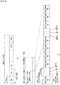
- FIG. 6 illustrates one example of an architecture of a radio frame in 3GPP LTE/LTE-A to which the present invention may be applied.
- a radio frame means a unit of data exchanged and carried by various protocols or a unit of exchanging data, and may be referred to as a PDU.
- uplink/downlink data packet transmission is performed by the unit of a subframe and one subframe is defined as a predetermined time interval including multiple OFDM symbols.
- a 3GPP LTE/LTE-A standard supports radio frame structure type 1 applicable to frequency division duplex (FDD) and radio frame structure type 2 applicable to time division duplex (TDD).
- FDD frequency division duplex
- TDD time division duplex
- uplink transmission and downlink transmission are performed while occupying different frequency bands.
- uplink transmission and downlink transmission are performed while occupying different frequency bands.
- a channel response of the TDD scheme is substantially reciprocal. This means that a downlink channel response and an uplink channel response are almost the same in a given frequency domain.
- the downlink channel response may be obtained from the uplink channel response.
- downlink transmission by the BS and uplink transmission by the UE may not be simultaneously performed since the uplink transmission and the downlink transmission are time-divisional in the entire frequency band.
- the uplink transmission and the downlink transmission are performed in different subframes.
- FIG. 6(a) above illustrates an architecture of radio frame type 1.
- a downlink radio frame is constituted by 10 subframes and one subframe is constituted by two slots in the time domain.
- a time required for transmitting one subframe is referred to as a transmission time interval (TTI).
- TTI transmission time interval
- a length of one subframe may be 1 ms and the length of one slot may be 0.5 ms.
- One slot includes a plurality of orthogonal frequency division multiplexing (OFDM) symbols in the time domain and includes a plurality of resource blocks (RBs) in the frequency domain. Since the 3GPP LTE / LTE-A uses OFDMA in the downlink, the OFDM symbol is intended to represent one symbol period.
- the OFDM symbol may be referred to as one SC-FDMA symbol or symbol period.
- a resource block as a resource allocation unit includes a plurality of consecutive subcarriers in one slot.
- the number of OFDM symbols included in one slot may vary according to a configuration of a cyclic prefix (CP).
- the CP includes an extended CP and a normal CP.
- the number of OFDM symbols included in one slot may be seven.
- the OFDM symbol is configured by the extended cyclic prefix, since the length of one OFDM symbol increases, the number of OFDM symbols included in one slot is smaller than that of the normal cyclic prefix.
- the extended cyclic prefix for example, the number of OFDM symbols included in one slot may be six. If a channel condition is unstable like a case where the UE moves at a high speed, the extended cyclic prefix may be used to further reduce intersymbol interference.
- one slot includes 7 OFDM symbols, so one subframe includes 14 OFDM symbols.
- first maximum three OFDM symbols of each subframe may be allocated to the physical downlink control channel (PDCCH) and the remaining OFDM symbols may be allocated to the physical downlink shared channel (PDSCH).
- PDCCH physical downlink control channel
- PDSCH physical downlink shared channel
- Radio frame type 2 is constituted by two half frames, each half frame is constituted by five subframes, and one subframe is constituted by two slots.
- a special subframe among five subframes is constituted by a downlink pilot time slot (DwPTS), a guard period (GP), and an uplink pilot time slot (UpPTS).
- the DwPTS is used for initial cell search, synchronization, or channel estimation in the UE.
- the UpPTS is used to match the channel estimation at the BS and uplink transmission synchronization of the UE.
- the guard period is a period for eliminating interference caused in the uplink due to a multi-path delay of a downlink signal between the uplink and the downlink.
- the architecture of the radio frame is merely an example and the number of subframes included in the radio frame or the number of slots included in the subframe and the number of symbols included in the slot may be variously changed.
- FIG. 7 is a diagram exemplifying a resource grid for one downlink slot in a wireless communication system to which the present invention may be applied.
- one downlink slot includes the plurality of OFDM symbols in the time domain.
- one downlink slot includes 7 OFDM symbols, and one resource block includes 12 subcarriers in the frequency domain, but the present invention is not limited thereto.
- Each element on the resource grid is referred to as a resource element (RE) and one resource block includes 12 ⁇ 7 resource elements.
- the resource element on the resource grid may be identified by an in-slot index pair (k, I).
- the number NRB of resource blocks included in THE downlink slot depends on a downlink transmission bandwidth.
- the structure of the uplink slot may be the same as the structure of the downlink slot.
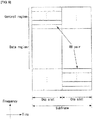
- FIG. 8 illustrates an architecture of a downlink subframe in a wireless communication system to which the present invention may be applied.
- a maximum of first three OFDM symbols in a first slot in the subframe are control regions in which control channels are allocated and the remaining OFDM symbols are data regions in which PDSCHs are allocated.
- Examples of downlink control channels used in 3GPP LTE/LTE-A include PCFICH, PDCCH, PHICH, and the like.
- the PCFICH is transmitted in the first OFDM symbol of the subframe and carries information on the number (i.e., a size of the control region) of OFDM symbols used for transmission of the control channels in the subframe.
- the PHICH is a response channel to the uplink and carries an ACK/NACK signal for the HARQ.
- Control information transmitted through the PDCCH is referred to as downlink control information (DCI).
- the downlink control information includes uplink resource allocation information, downlink resource allocation information, or an uplink transmission (Tx) power control command for an arbitrary UE group.
- the BS determines a PDCCH format according to the DCI to be sent to the UE and attaches cyclic redundancy check (CRC) to the control information.
- the CRC is masked with a radio network temporary identifier (RNTI) according to an owner or a purpose of the PDCCH.
- RNTI radio network temporary identifier
- the CRC may be masked with a unique identifier (e.g., cell-RNTI (C-RNTI)) of the UE in the case of the PDCCH for specific UE.
- C-RNTI radio network temporary identifier
- the CRC may be masked with a paging indication identifier (e.g., paging-RNTI (P-RNTI)).
- P-RNTI paging-RNTI
- the CRC may be masked with a system information-RNTI (SI-RNTI). Further, the CRC may be masked with a random access-RNTI (RA-RNTI) in order to indicate a random access response which is a response to transmission of a random access preamble of the UE.
- SI-RNTI system information-RNTI
- RA-RNTI random access-RNTI
- FIG. 9 illustrates an architecture of an uplink subframe in a wireless communication system to which the present invention may be applied.
- the uplink subframe may be divided into the control region and the data region in the frequency domain.
- the PUCCH carrying the uplink control information is allocated to the control region.
- the PUSCH carrying the user data is allocated to the data region.
- the UE may support simultaneous transmission of the PUSCH and the PUCCH.
- the resource block pair within the subframe is allocated to the PUCCH for one UE.
- the resource blocks which belong to the resource block pair allocated to the PUCCH occupy different subcarriers in two slots, respectively based on a slot boundary. In this case, the resource block pair allocated to the PUCCH frequency-hops in the slot boundary.
- PDCCH Physical Downlink Control Channel
- Control information transmitted through the PDCCH is referred to as a downlink control indicator (DCI).
- DCI downlink control indicator
- the size and the purpose of the control information vary according to the DCI format and the PDCCH may vary in size according to a coding rate.
- Table 1 shows the DCI depending on the DCI format.
- DCI format Objectives 0 Scheduling of PUSCH 1 Scheduling of one PDSCH codeword 1A Compact schedulin of one PDSCH codeword 1B Closed-loop single-rank transmission 1C Paging, RACH response and dynamic BCCH 1D MU-MIMO 2 Scheduling of rank-adapted closed-loop spatial multiplexing mode 2A Scheduling of rank-adapted open-loop spatial multiplexing mode 3 TPC commands for PUCCH and PUSCH with 2bit power adjustments 3A TPC commands for PUCCH and PUSCH with single bit power adjustments 4 the scheduling of PUSCH in one UL cell with multi-antenna port transmission mode
- the DCI includes format, format 0 for PUSCH scheduling, format 1 for scheduling one PDSCH codeword, format 1A for compact scheduling of one PDSCH codeword, format 1C for simple scheduling, format 2 for PDSCH scheduling in a closed-loop spatial multiplexing mode, format 2A for PDSCH scheduling in an open loop spatial multiplexing mode, formats 3 and 3A for transmission of a transmission power control (TPC) command, and format 4 for PUSCH scheduling in one uplink cell in a multi-antenna port transmission mode.
- TPC transmission power control
- DCI format 1A may be used for PDSCH scheduling regardless of which transmission mode is set in the UE.
- Such DCI format may be independently applied for each UE and the PDCCHs of multiple UE in one subframe may be simultaneously multiplexed.
- the PDCCH is configured by one control channel element or an aggregation of several consecutive control channel elements (CCEs).
- the CCE is a logical allocation unit used to provide the PDCCH with the coding rate according to a state of a radio channel.
- the CCE is a unit corresponding to nine sets of REGs consisting of four resource elements.
- the BS may use ⁇ 1, 2, 4, 8 ⁇ CCEs in order to configure one PDCCH signal and ⁇ 1, 2, 4, 8 ⁇ in this case is called a CCE aggregation level.
- the number of CCEs used for transmission of a specific PDCCH is determined by the BS according to the channel state.
- the PDCCH configured according to each UE is interleaved and mapped into a control channel region of each subframe according to a CCE-to-RE mapping rule.
- the location of the PDCCH may vary depending on the number of OFDM symbols for the control channel of each subframe, the number of PHICH groups, a transmission antenna, and a frequency transition.
- channel coding is independently performed on the PDCCH of each multiplexed UE and the cyclic redundancy check (CRC) is applied.
- the CRC is masked with a unique identifier (UE ID) of each UE to allow the UE to receive the PDCCH thereof.
- UE ID unique identifier
- the BS does not provide information on where the corresponding PDCCH is located to the UE.
- the UE Since the UE may not know at which position, at which CCE aggregation level or DCI format the PDCCH of the UE is transmitted in order to receive the control channel transmitted from the BS, the UE monitors an aggregation of PDCCH candidates in the subframe to find the PDCCH of the UE. This is called blind decoding (BD).
- the blind decoding may be referred to as blind detection or blind search.
- the blind decoding refers to a method in which the UE de-masks the CRC part with the UE ID and then checks a CRC error to verify whether the corresponding PDCCH is the control channel of the UE.
- the RRC state refers to whether the RRC layer of the UE is logically connected with the RRC layer of the E-UTRAN and a case where the RRC layer of the UE is connected with the RRC layer of the RRC layer of the E-UTRAN is called an RRC connected state and a case where the RRC layer of the UE is not connected with the RRC layer of the E-UTRAN is called an RRC idle state. Since the RRC connection exists in the UE in the RRC connected state, the E-UTRAN may determine the existence of the corresponding UE by the unit of the cell, thereby effectively controlling the UE.
- the UE in the RRC idle state may not be determined by the E-UTRAN and is managed by the unit of a tracking area which is a larger region unit than the cell by a core network (CN). That is, it is determined only whether the UE in the RRC idle state exists by the unit of the larger region and the UE in the RRC idle state needs to move to the RRC connected state in order to receive a normal mobile communication service such as voice and data.
- CN core network
- the UE When a user first turns on a power of the UE, the UE first searches an appropriate cell and then stays in the RRC idle state in the corresponding cell.
- the UE in the RRC idle state needs to establish an RRC connection
- the UE in the RRC idle state establishes the RRC connection with the E-UTRAN through an RRC connection procedure and transitions to the RRC connection state.
- the case may correspond to response message transmission thereto.
- a non-access stratum (NAS) layer positioned above the RRC layer performs such as session management and mobility management.
- NAS non-access stratum
- EMM-REGISTERED EPS mobility management- registered
- EMM-deregistered two states of EPS mobility management- registered (EMM-REGISTERED) and EMM-deregistered are defined in order to management the mobility of the UE and the two states are applied to the UE and the MME.
- Initial UE is in the EMM-deregistered state and the UE performs a process of registering the UE in the corresponding network through an initial attach procedure in order to access the network.
- the attach procedure is successfully performed, the UE and the MME are in the EMM-registered state.
- ECM EPS connection management
- ECM-CONNECTED Two states of an EPS connection management (ECM)-IDLE state and an ECM-CONNECTED state are defined in order to manage signaling connection between the UE and the EPC and the two states are applied to the UE and the MME.
- ECM EPS connection management
- the two states are applied to the UE and the MME.
- the MME in the ECM-idle state When the MME in the ECM-idle state establishes the S1 connection with the E-UTRAN, the MME becomes in the ECM-connected state.
- the ECM-IDLE state the E-UTRAN has no context information of the UE. Accordingly, the UE in the ECM-idle state performs a UE-based mobility-related procedure such as cell selection or cell reselection without receiving the command of the network.
- the UE is in the ECM-connected state, the mobility of the UE is managed by the command of the network.
- the position of the UE in the ECM-idle state is different from a position known by the network, the UE notifies the corresponding position of the UE to the network through a tracking area update procedure.
- the system information includes essential information which the UE needs to know in order to access the BS. Therefore, the UE needs to all of the system information before accessing the BS and further, needs to continuously latest system information. In addition, since the system information is information which all UE in one cell needs to know, the BS periodically transmits the system information.
- the system information is divided into a master information block (MIB), a scheduling block (SB), and a system information block (SIB).
- MIB allows the UE to know a physical configuration of the cell, for example, a bandwidth.
- the SB informs transmission information of the SIBs, for example, a transmission period.
- the SIB is a collection of the system information related to each other. For example, some SIBs only contain only information of an adjacent cell and some SIBs contain only information of the uplink radio channel used by the UE.
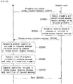
- FIG. 10 is a flowchart illustrating a process of establishing RRC connection to which the present invention may be applied.
- the UE transmits an RRC connection request message for requesting the RRC connection to the network (S10010).
- the network transmits an RRC connection setup message as a response to the RRC connection request (S10020).
- the UE enters an RRC connection mode after receiving the RRC connection setup message.
- the UE transmits to the network an RRC connection setup complete message used for verifying successful completion of RRC connection establishment (S10030).
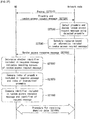
- FIG. 11 is a flowchart illustrating an RRC connection reconfiguration process to which the present invention may be applied.
- RRC connection reconfiguration is used to modify the RRC connection. This is used for establishment/modification/release, handover execution, measurement setup/modification/release of the radio bearer (RB).
- RB radio bearer
- the network transmits an RRC connection reconfiguration message for modifying the RRC connection to the UE (S11010).
- the UE transmits to the network an RRC connection reconfiguration complete message used for verifying successful completion of RRC connection reconfiguration as a response to the RRC connection reconfiguration (S11020).
- a scheduling-based data transmission/reception method of the BS is used to maximize utilization of resources. This means that when there is data to be transmitted by the UE, the BS may firstly request the uplink resource allocation to the BS and transmit data using only the uplink resources allocated from the BS.
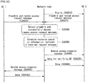
- FIG. 12 is a diagram exemplifying an uplink resource allocation process of a UE in a wireless communication system to which the present invention may be applied.
- the BS In order to efficiently use the uplink radio resource, the BS needs to know what types of data and how much data is to be transmitted on the uplink for each UE. Accordingly, the UE may directly transmit information on uplink data to be transmitted to the BS and the BS may allocate the uplink resource to the UE based on the information.
- the information on the uplink data transmitted from the UE to the BS is referred to as a buffer status report (BSR) as the amount of the uplink data stored in a buffer.
- BSR buffer status report
- the BSR is transmitted using a MAC control element when the UE is allocated resources on the PUSCH in the current TTI and a reporting event is triggered.
- FIG. 12(a) above illustrates an uplink resource allocation process for actual data when an uplink radio resource for buffer status reporting (BSR) is not allocated to the UE. That is, since a UE switching a state of an active mode in a DRX mode has no data resource which is allocated in advance, the UE needs to request the resource for the uplink data starting from SR transmission through the PUCCH and in this case, an uplink resource allocation procedure of 5 steps is used.
- BSR buffer status reporting
- the UE when a PUSCH resource for transmitting the BSR is not allocated to the UE, the UE first transmits the scheduling request (SR) to the BS in order to allocate the PUSCH resource (S12010).
- SR scheduling request
- a reporting event occurs in the scheduling request, but when the UE does not schedule the radio resource onto the PUSCH at a current TTI, the scheduling request is used for the UE to request the PUSCH resource in order to be allocated the PUSCH resource for uplink transmission.
- the UE transmits the SR on the PUCCH when a regular BSR is triggered but does not have the uplink radio resource for transmitting the BSR to the BS.
- the UE transmits the SR through the PUCCH or initiates the random access procedure according to whether the PUCCH resource for the SR is configured.
- the PUCCH resource in which the SR may be transmitted is configured by the upper layer (e.g., RRC layer) in a UE-specific manner.
- the SR configuration includes SR periodicity and SR offset information.
- the UE When receiving a UL grant for the PUSCH resource for the BSR transmission from the BS (S12020), the UE transmits the BSR triggered through the PUSCH resource allocated by the UL grant to the BS (S12030).
- the BS checks the amount of data to be transmitted on the uplink by the actual BS through the BSR and transmits the UL grant for the PUSCH resource for the actual data transmission to the UE (S12040).
- the UE receiving the UL grant for the actual data transmission transmits actual uplink data to the BS through the allocated PUSCH resource (S12050).
- FIG. 12(b) above exemplifies an uplink resource allocation process for actual data when the uplink radio resource for the BSR is allocated to the UE.
- the UE transmits the BSR through the allocated PUSCH resource and transmits the scheduling request to the BS together with the BSR (S12110).
- the BS verifies the amount of data which the actual UE is to transmit on the uplink through the BSR and transmits the UL grant for the PUSCH resource for the actual data transmission to the UE (S12120).
- the UE receiving the UL grant for the actual data transmission transmits the actual uplink data to the BS through the allocated PUSCH resource (S12130).
- Random access procedure Random access procedure
- FIG. 13 illustrates one example of a random access procedure in an LTE system.
- the random access procedure is performed at the initial access in the RRC_IDLE, the initial access after the radio link failure, handover requesting the random access procedure, and the uplink or downlink data generation requiring the random access procedure during the RRC_CONNECTED.
- Some RRC messages including an RRC connection request message, a cell update message, an UTRAN registration area (URA) update message, and the like are also transmitted by using the random access procedure.
- a logical channel common control channel (CCCH), a dedicated control channel (DCCH), and a dedicated traffic channel (DTCH) may be mapped to a transport channel RACH.
- the transport channel RACH is mapped to a physical random access channel (PRACH).
- the UE physical layer When the MAC layer of the UE instructs a UE physical layer to transmit the PRACH, the UE physical layer first selects one access slot and one signature and transmits A PRACH preamble to the uplink.
- the random access procedure is divided into a contention-based random access procedure and a non-contention based random access procedure.
- FIG. 13(a) above illustrates an example of a contention based random access procedure
- FIG. 13(b) above illustrates an example of a non-contention based random access procedure.
- the UE receives and stores information on the random access from the BS through the system information. Thereafter, when the random access is required, the UE transmits a random access preamble (also referred to as message 1) to the BS (S13010).
- a random access preamble also referred to as message 1
- the BS When the BS receives the random access preamble from the UE, the BS transmits a random access response message (also referred to as message 2) to the UE (S13020).
- a random access response message (also referred to as message 2)
- downlink scheduling information for the random access response message may be CRC-masked with a random access-radio network temporary identifier (RA-RNTI) and transmitted on an L1 or L2 control channel (PDCCH).
- RA-RNTI random access-radio network temporary identifier
- the UE receiving the downlink scheduling signal masked with the RA-RNTI may receive and decode the random access response message from a physical downlink shared channel (PDSCH). Thereafter, the UE checks whether the random access response information indicated to the UE exists in the random access response message.
- PDSCH physical downlink shared channel
- Whether there is the random access response information indicated to the UE may be confirmed by whether there is a random access preamble ID (RAID) for the preamble transmitted by the UE.
- RAID random access preamble ID
- the random access response information includes timing alignment (TA) indicating timing offset information for synchronization, radio resource allocation information used in the uplink, temporary ID (e.g., temporary C-RNTI) for terminal identification, and the like.
- TA timing alignment
- radio resource allocation information used in the uplink
- temporary ID e.g., temporary C-RNTI
- the UE When receiving the random access response information, the UE performs uplink transmission (also referred to as message 3) on the uplink shared channel (S-SCH) according to the radio resource allocation information included in the response information (S 13030).
- the uplink transmission may be expressed as scheduled transmission.
- the BS After receiving the uplink transmission from the UE, the BS transmits a message (also referred to as message 4) for contention resolution to the UE through a downlink shared channel (DL-SCH).
- a message also referred to as message 4
- DL-SCH downlink shared channel
- the BS allocates a non-contention random access preamble to the UE (S13110).
- the non-contention random access preamble may be allocated through a handover command or dedicated signaling such as the PDCCH.
- the UE transmits the non-contention random access preamble allocated to the BS (S13120).
- the BS may transmit the random access response (also referred to as message 2) to the UE similar to step S2002 in the contention based random access procedure (S13130).
- the HARQ is not applied to the random access response, but the HARQ may be applied to a message for uplink transmission or contention resolution for the random access response. Therefore, the UE does not need to transmit the ACK or NACK for the random access response.
- a cellular system such as an LTE(-A) system or an 802.16m system uses a BS scheduling-based resource allocation scheme.
- a UE having data (i.e., UL data) to be transmitted in a system using the BS scheduling-based resource allocation scheme requests to the BS a resource for the corresponding data transmission before transmitting data.
- Such a scheduling request by the UE may be performed through scheduling request (SR) transmission to the PUCCH or buffer status report (BSR) transmission to the PUSCH.
- SR scheduling request
- BSR buffer status report
- the UE may request the uplink resource to the BS through an RACH procedure.
- the BS that receives the scheduling request from the UE allocates the uplink resource to be used by the corresponding UE to the UE through a downlink control channel (i.e., an UL grant message and a DCI for LTE(-A)).
- a downlink control channel i.e., an UL grant message and a DCI for LTE(-A)
- the UL grant transmitted to the UE may be notified by explicitly signaling to which subframe resource the resource allocated to the UE corresponds, but the resource is allocated to a subframe after a specific time (e.g., 4 ms in the case of the LTE) to define an appointed time between the UE and the BS.
- a specific time e.g. 4 ms in the case of the LTE
- allocating, by the BS, the resources after Xms (e.g., 4 ms in the case of the LTE(-A)) to the UE means allocating, by the UE, the resources of the UE by considering both a time of receiving and decoding the UL grant and a time of preparing and encoding the data to be transmitted.
- Xms e.g. 4 ms in the case of the LTE(-A)
- EMM EPS mobility management
- ECM EPS connection management
- FIG. 14 is a diagram exemplifying EMM and ECM states in a wireless communication system to which the present invention may be applied.
- an EMM registered state and an EMM-deregistered state may be defined according to whether the UE is attached to or detached from the network.
- the EMM registered state and the EMM-deregistered state may be applied to the UE and the MME.
- the initial UE is in the EMM-DEREGISTERED state and the UE performs a process of registering the UE in the corresponding network through the initial attach procedure in order to access the network.
- the attach procedure is successfully performed, the UE and the MME are transitioned to the EMM-registered state.
- the UE is powered off or the radio link is unsuccessful (when a packet error rate exceeds a reference value on the radio link), the UE is detached from the network and transitioned to the EMM-deregistered state.
- an ECM connected state and an ECM idle state may be defined in order to manage the signaling connection between the UE and the network.
- the ECM connected state and the ECM idle state may also be applied to the UE and the MME.
- the ECM connection is constituted by the RRC connection established between the UE and the BS and the S1 signaling connection established between the BS and the MME. That is, the ECM connection is configured/cancelled means that both the RRC connection and the S1 signaling connection are configured/cancelled.
- the RRC state indicates whether the RRC layer of the UE and the RRC layer of the BS are logically connected. That is, when the RRC layer of the UE and the RRC layer of the BS are connected, the UE is in the RRC_CONNECTED state. When the RRC layer of the UE and the RRC layer of the BS are not connected, the UE is in the RRC_IDLE state.
- the network may grasp the existence of the UE in the ECM connected state in a cell unit and effectively control the UE.
- the network may not determine the existence of the UE in the ECM idle state and is managed by the unit of the tracking area which is the larger region unit than the cell by a core network (CN).
- the UE When the UE is in the ECM idle state, the UE performs discontinuous reception (DRX) configured by the NAS using an ID uniquely allocated in the tracking area. That is, the UE may receive broadcasts of system information and paging information by monitoring the paging signal at a specific paging time for each UE-specific paging DRX cycle.
- DRX discontinuous reception
- the network has no context information of the UE. Accordingly, the UE in the ECM idle state performs a UE-based mobility-related procedure such as cell selection or cell reselection without receiving the command of the network.
- a UE-based mobility-related procedure such as cell selection or cell reselection without receiving the command of the network.
- the UE notifies the corresponding position of the UE to the network through a tracking area update (TAU) procedure.
- TAU tracking area update
- the mobility of the UE is managed by the command of the network.
- the network knows the cell to which the UE belongs in the ECM connected state.
- the network may transmit and/or receive data to/from the UE, control mobility such as UE handover, and perform cell measurements for the adjacent cell.
- the UE in order for the UE to receive a normal mobile communication service such as voice or data, the UE needs to be transitioned to the ECM connected state.
- the initial UE is in the ECM idle state similar to the EMM state as in the case where the UE is first turned on and when the UE is successfully registered in the corresponding network through the initial attach procedure, the UE and the MME are transitioned to the ECM connected state.
- the UE is registered in the network but the traffic is inactivated and the radio resource is not thus allocated, the UE is in the ECM idle state and when new uplink or downlink traffic is generated in the UE, the UE and the MME is transitioned to the ECM connected state.
- FIG. 15 is a diagram illustrating one example of a wireless communication system architecture for supporting a next-generation RAN to which methods proposed by the present specification may be applied.
- the wireless communication system structure for supporting the next-generation RAN may be expressed as a 'high level architecture'.
- next generation may be briefly expressed as "Next Gen” or the like and the next generation may collectively refer to terms referring to future communication generations including 5G and the like.
- next generation will hereinafter be referred to as "Next Gen”.
- the structure of the "Next Gen” may support new RAT(s), evolved LTE, and non-3GPP access types.
- Examples of the non-3GPP access types may include WLAN access, Fixed access, and the like.
- next Gen structure supports a unified authentication framework for other access systems and supports simultaneous connection with multiple UE through multiple access technologies.
- next Gen structure allows independent evolution of the core network and RAN and minimizes access dependency.
- next Gen structure supports separation of control plane and user plane functions and supports transmission of IP packets, non-IP PDUs, and Ethernet frames.
- the "Next Gen” structure may include NextGen UE 1510, NextGen RAN 1520, NextGen Core 1530, and Data network 1540.
- the UE may be expressed as 'NextGen UE'
- the RAN defining the radio protocol structure between the UE and the BS may be expressed as 'NextGen RAN'
- the core network may be expressed as 'NextGen Core'.
- 'NextGen RAN' may correspond to E-UTRAN in the LTE(-A) system
- 'NextGen Core' may correspond to EPC in the LTE(-A) system
- network entities performing functions including MME, S-GW, P-GW, etc., in the LTE EPC may also be included in the NextGen Core.
- An NG1-C interface and an NG1-U interface exist between the NextGen RAN and the NextGen Core and an NG-Gi interface exists between the NextGen Core and the Data Network.
- NG1-C represents a reference point for the control plane between the NextGen RAN and the NextGen Core
- NG1-U represents a reference point for the user plane between the NextGen RAN and the NextGen Core.
- NG-NAS represents a reference point for the control plane between the NextGen UE and the NextGen Core.
- NG-Gi represents a reference point between the NextGen Core and the data network.
- the data network may be an operator external public network or a private data network or an intra-operator data network.
- FIG. 16 is a diagram illustrating one example of a flow based QoS architecture to which the methods proposed by the present specification may be applied.
- FIG. 16 specifically illustrates the interface between UE, AN, and AF in detail by dividing the NextGen Core of FIG. 15 above into a control plane (CP) function and a user plane (UP) function.
- CP control plane
- UP user plane
- a policy of a quality of service (QoS) in a wireless communication system to which the present invention is applied may be stored and configured in a control plane (CP) function 16030 for the following reasons.
- QoS quality of service
- CP control plane
- Flow Priority Indicator represents a parameter for defining a priority of each flow process in UP functions 16040 and AN functions 16020. This corresponds to a scheduling priority and a priority in a congestion case.
- the FPI indicates whether the flow requires a guaranteed flow bit rate and/or a maximum flow bit rate.
- Flow Descriptor Packet filters related with a specific flow process. Identification in the uplink needs to be performed in the UE and the AN 1020, but is limited to layer 3 and layer 4.
- MFB Maximum Flow Bitrate
- the parameter represents a maximum authorized bit rate authorized for a data flow.
- Flow Priority Level Parameter for defining a static significance of the flow for accessing the AN (16020) resource. Additionally, the FPL indicates whether to access an AN (16020) non-prioritized resource.
- the AN non-prioritized resource needs to be an allocated resource that is either pre-emptable or protected from pre-emption.
- Session Bitrate parameter indicating the bit rate value in the uplink and downlink for establishing a user session.
- the Session Bitrate parameter represents the maximum bit rate allowed for the user session.
- the support of the GFP in the UE depends on a QoS design of the radio interface.
- the CP functions and the UP functions are functions included in the NextGen CN (indicated by a dotted line) and may be implemented by one physical device or by different physical devices.
- FIG. 17 is a diagram illustrating one example of a QoS architecture used in a QoS framework to which the methods proposed by the present specification may be applied.
- the CAF-Core 17030 supports a mechanism for identifying application sessions (e.g., downloading video, downloading web pages, listening to music, posting for a social media network, etc.) and enforcing QoS policies associated with the discovered applications.
- application sessions e.g., downloading video, downloading web pages, listening to music, posting for a social media network, etc.
- QoS policies associated with the discovered applications.
- the CAF-Core receives the QoS policies from a Core CP.
- Application discovery is accomplished by means of non-standardized algorithms (e.g., usage patterns, heuristics, SNF discovery for encrypted traffic, etc.).
- the CAF performs QoS enforcement on the CN based on the QoS policies received from the Core Cp.
- the CAF-Core may handle the QoS policies and obtain dynamic QoS targets and local enforcement actions in the CN.
- the CAF-Core may update the dynamic QoS targets and the local enforcement actions in real time based on current content requirements of user plane traffic mix, simultaneous competing flows, and network status and resource availability within the limits of the QoS policies provided by the NG Core CP functions. As such, the CAF-Core enforces the QoS policies within the given policy limits and will not deviate out of any range.
- the CAF-RAN 17010 supports a mechanism for identifying the application sessions (e.g., downloading video, downloading web pages, listening to music, posting for a social media network, etc.) and enforcing the QoS policies.
- the CAF-RAN receives the QoS policies from the Core CP.
- the CAF-RAN may use the application discovery information provided by the Core, the application discovery information may imply additional specific requirements for a certain application session, and at the same time, may form traffic for a given session.
- the CAF-RAN performs QoS enforcement based on the QoS policies received from the Core CP. This includes traffic forming for DL and UL. The DL traffic forming helps control the flow of UL traffic.
- the CAF-RAN may handle the QoS policies and obtain the dynamic QoS targets and local enforcement actions in the RAN.
- the CAF-RAN may update the dynamic QoS targets and the local enforcement actions in real time based on the current content requirements of user plane traffic mix, simultaneous competing flows, and network status and resource availability within the limits of the QoS policies provided by the NG Core. As such, the CAF-RAN enforces the QoS policies within the given policy limits and will not deviate out of any range.
- the RAN is limited by the charging performed in the core and thus has no effect on the charging performed in the UP function in the core.
- the amount of specific traffic charged by the core is provided to the RAN in conjunction with packet marking with application marking and the CAF-RAN enforces and conserves the charged capacity in relation to the bits.
- the CAF-Core may perform the application discovery and provide information in the form of the packet marking based on the policies received from the CN CP.
- the traffic forming and the policy enforcement in the CAF-RAN are limited by the packet marking represented by the policies received from the CAF-Core and the CN CP. This helps the CAF-Core and the CAF-RAN to operate in a cooperative manner and the charging is also performed for the application represented by the CAF-Core.
- the CN CP function and the CN UP function may be implemented by one physical device or respective physical devices.
- the QoS policies are stored in the CN CP Functions. In session formation, Subscriber and application specific policies are transmitted to the RAN and the CAF which exists in the CN UP function.
- the UP function is responsible for traffic charging support (CDR, granted quota for on-line) based on policies that take into account an outcome of the CAF. Further, the CN UP function marks downlink traffic transmitted to the RAN.
- CDR traffic charging support
- the CN UP function marks downlink traffic transmitted to the RAN.
- the operator supplies specific QoS policies to the subscribers and applications of the NG Core Cp function.
- the CP function of the Core provides the policies to the RAN and CN UP functions.
- the enforcement actions are obtained from the policy points according to the current content requirements of the user plane traffic mix, simultaneous competing flows, and network status and resource availability.
- Traffic charging (30020) support (CDR, granted quota for on-line) based on policies that take into account an outcome of the CAF is performed in the CN UP function.
- the following shows different configurations of the QoS policies provided by the UP functions and the RAN.
- Intent level QoS policies that show the configuration of floors may be identified by the packet marking, SDF descriptor, and the like in an abstract QoS target (e.g., Voice type Qos, Smoothed Bit rate Qos (limit the bandwidth variation for the traffic), bulk traffic (when a radio condition is bad or a load on the cell is excessive, the traffic may be discarded)).
- an abstract QoS target e.g., Voice type Qos, Smoothed Bit rate Qos (limit the bandwidth variation for the traffic), bulk traffic (when a radio condition is bad or a load on the cell is excessive, the traffic may be discarded).
- Transmission QoS level policies that show the configuration of the floor may be identified by the packet marking, the SDF descriptors, etc. in explicit QoS targets (priority, delay, jitter, etc.).
- the CP functions of the CAF-RAN and the CAF-Core are responsible for local CAF policies and Transport locally map Intent level QoS policies which belong to QoS level policies based on local (radio) conditions (current context of user plane traffic mix, simultaneous competing flows and network status and resource availability) and are limited by upper limits of Intent level QoS policies.
- FIG. 18 is a flowchart illustrating one example of a method for transmitting uplink data in a state in which UE is not connected with a network node to which the present invention may be applied.
- FIGS. 18(a) and 18(b) above illustrate a process in which the UE transmits uplink data by being allocated resources from the BS in a process of performing the random access procedure for establishing the connection with the BS.
- the procedure for transmitting/receiving data in a state where the UE is not connected to the BS may be called a connectionless based data transmission procedure or an RRC connectionless transmission procedure.
- the UE performs the random access procedure to establish the connection with the BS (S18010).
- the random access procedure means performing only steps S13010 and S13020 described in FIG. 13(a) above.
- the random access procedure means only a step in which the UE transmits the random access preamble to the BS and receives the random access response message in response to the random access preamble.
- the random access response message may include an index of a preamble discovered by the BS, timing alignment (TA) indicating timing offset information for synchronization, radio resource allocation information used in the uplink, temporary ID (e.g., temporary C-RNTI) for terminal identification, and the like.
- TA timing alignment
- radio resource allocation information used in the uplink
- temporary ID e.g., temporary C-RNTI
- the UE transmits the uplink data to the BS (or network node) through the allocated resource (S18020).
- the UE requests a resource for transmission of the uplink data to transmit the uplink data as illustrated in FIG. 18(b) .
- the UE that performs the random access procedure transmits a resource request message in order to request the resource for transmitting the uplink data to the network node (S18110 and S18120).
- the request message may include size information of the uplink data or size information of a resource to be allocated to request the resource for transmission of the uplink data.
- the network node allocates the resource to the UE according to the request message and transmits the allocated resource information included in the response message to the UE (S18030).
- the UE transmits the uplink data to the network node through the resource allocated by the network node (S18140).
- the UE may be allocated the resource from the network node and transmit the uplink data.
- FIG. 19 is a flowchart illustrating one example of a method for receiving downlink data in a state in which UE is not connected with a network node to which the present invention may be applied.
- FIGS. 19(a) and 19(b) above illustrate a process in which the UE transmits downlink data by being allocated resources from the BS in the process of performing the random access procedure for establishing the connection with the BS.
- the procedure for transmitting/receiving data in a state where the UE is not connected to the BS may be called a connectionless based data transmission procedure or an RRC connectionless transmission procedure.
- the network node when the downlink data transmitted to the UE is generated, the network node transmits a paging message to wake up the UE because the UE is not connected with the network node (S19010).
- the UE and the network node perform the random access procedure in the same manner as in step 18010 of FIG. 18 above (S19020) and transmit data for verification of the UE to the network node through the resource allocated in the random access procedure (S19030).
- the data for verifying the terminal may include a UE ID for identifying the UE, a security header type (e.g., not security protected, integrity protected, integrity protected and ciphered, etc.), a key set identifier for identifying a security context, a NAS count, and a message authentication code (MAC).
- a security header type e.g., not security protected, integrity protected, integrity protected and ciphered, etc.
- key set identifier for identifying a security context
- NAS count e.g., a message authentication code (MAC).
- MAC message authentication code
- the network node When verification of the UE is completed, the network node transmits the downlink data to the UE (S19040).
- the UE requests the resource to transmit the data for verifying the UE as illustrated in FIG. 19(b) above.
- the UE that performs the random access procedure transmits the resource request message in order to request the resource for transmitting the data for verifying the UE to the network node (S19110, S19120, and S19130).
- the request message may include size information of the data for verifying the UE or size information of a resource to be allocated to request the resource for transmission of the data for verifying the UE.
- the network node allocates the resource to the UE according to the request message and transmits the allocated resource information included in the response message to the UE (S19140).
- the UE transmits the data for verifying the UE to the network node through the resource allocated by the network node (S19150).
- the network node transmits the downlink data to the UE (S19160).
- the UE may be allocated the resource from the network node and transmit the data for verifying the UE and receive the downlink data through the verification of the UE.
- the UE transmits data to the network node through a non-method as in the methods described with reference to FIGS. 18 and 19 , since the required quality varies depending on the service, the resources need to be differentially allocated to the UE according to the requirement of the service.
- the resources need to be differentially allocated to the UE according to the requirements of the respective services.
- the following services may exist.
- Ultra-high availability and reliability e.g., 3D connectivity services such as life-friendly eHealth services and public safety service drone
- Table 2 No. 13 Ultra-high availability and reliability Main Attributes Requirement KPI
- User Experienced Data Rate also at the cell edqe
- DL 10Mbps
- Data rate enabling real-time video
- UL 10Mpbs
- data transfers e.g. maps
- the following services may exist.
- the present invention proposes a method for transmitting data for providing the service by allocating the resources differentially to the UE according to the requirements of the service.
- FIG. 20 is a flowchart illustrating one example of a method for allocating resources according to information of data to be transmitted by UE to which the present invention may be applied.
- the network node may allocate the resource to transmit data in a non-connected state to the UE based on information related to the preamble transmitted and data to be transmitted by the UE.
- connection based data transmission/reception Non-connection based data transmission/reception Random access purpose of UE Acquisition of uplink resource Acquisition of uplink resource - Uplink data - Uplink data - UE verification related information for receiving downlink data - Information related to connection and mobility of UE Scheduling contention target in service aspect - Uplink data of each UE - Uplink data of each UE - UE verification related information for receiving downlink data Scheduling consideration element in service aspect - Uplink data quality characteristic of each UE - Uplink data quality characteristic of each UE - Downlink data quality characteristic of each UE - Data transmission direction (additionally considered because different transmission/reception delay occurs according to data transmission direction)
- the resource for transmitting the data is limited, and the priority of the resource allocation needs to be determined according to the requirement of the service provided by the UE.
- the delay varies depending on whether the information related with the verification of the UE for receiving the uplink data or downlink data to be transmitted by the UE may be transmitted through the uplink resource acquired through the random access procedure, the size of the data needs to be also considered in the resource allocation.
- One example of a matter which needs to be considered for the resource allocation may include a delay time when the data is to be transmitted, the transmission direction of the data, a state of a channel, a transmission rate per second, an error rate, through which scheduler the resource is scheduled, an algorithm for the resource allocation, and the like.
- scheduling information The matter to be considered for the resource allocation is referred to as scheduling information.
- the BS needs to recognize the scheduling information and allocate the resources differentially according to the scheduling information.
- the UE needs to transmit the scheduling information to the BS.
- the network node transmits the downlink data to the UE
- the UE exists in an idle state, so that the network node transmits the paging message to the UE in order to wake up the UE (S20010).
- the paging message includes a UE ID indicating UE receiving the downlink data and quality of service (QoS) information indicating a quality required for transmission of the downlink data.
- QoS quality of service
- Step S20010 above may not be performed when the UE transmits the uplink data to the network node.
- the UE performs the random access procedure to transmit data for verification of the UE for transmission of the uplink data or downlink data in a state where the UE is not connected with the network node.
- the UE transmits a preamble (first preamble) and a random access request message for requesting random access and resource allocation to the network node (S20020).
- the random access request message includes scheduling information for resource allocation.
- the scheduling information may include the following information for allocating the resource to the UE by the network.
- Uplink data Quality characteristic of data to be transmitted by the UE
- Downlink data QoS information of the downlink data transmitted from the network node through the paging message
- an identifier (referred to as Q-value or a first identifier in the present invention) for solving the case
- the Q-value has a value other than a specific value (a value indicating unsuccessful decoding) of an identifier (Q-CR ID or second identifier in the present invention) regarding whether decoding the random access request message transmitted from the UE is successful and for the contention resolution.
- the preamble and the random access request message may be transmitted through different frequency bands at the same transmission time interval (TTI) or at different TTIs.
- TTI transmission time interval
- the network node that receives the access request message including the preamble and the scheduling information may allocate the resource to the UE based on the scheduling information.
- the network node transmits resource allocation information indicating the allocated resource, which is included in the random access response message to the UE (S20030).
- the random access response message may include an index (an index of a second preamble) of a preamble successfully discovered by the network node, a timing advance command (TAC), a radio network identifier (e.g., Temporary C-RNTI, etc.) which the network allocates to the UE, and identifiers (hereinafter, called Q-CR ID or a second identifier in the present invention) indicating the contention resolution and whether decoding the random access request message is successful, in addition to the resource allocation information.
- TAC timing advance command
- Q-CR ID e.g., Temporary C-RNTI, etc.
- the UE When the UE receives the random access response message from the network node, the UE transmits verification information of the UE for receiving the uplink data or downlink data based on the resource allocation information included in the random access response message (S20040).
- the UE may transmit clear scheduling information and data for resource allocation to the network node in the non-connected state and the network may allocate resources for differentially transmitting data to the UEs based on the scheduling information differentially.
- FIG. 21 is a flowchart illustrating one example of a method for transmitting data by being allocated resources by transmitting information of data to be transmitted to a network node by UE to which the present invention may be applied.
- the UE transmits information related to data to be transmitted to the network by the UE to be allocated the resource for transmitting the data from the network node.
- steps S21010 and S21020 are the same as steps S20020 and S20030 of FIG. 20 , and thus description thereof will be omitted.
- the UE Upon receiving the random request response message from the network node, the UE determines whether the network node decodes the random access request message transmitted by the network node.
- the UE determines whether the value of the Q-CR ID, which is an identifier indicating whether the contention resolution included in the random access response message and the random access request message are successfully decoded is a value indicating that the decoding is successful.
- the UE checks whether the value of the Q-CR ID of the random access response message is '0'.
- the UE determines that the network node successfully decodes the random access request message and when the resource indicated by the resource allocation information included in the random access response message is a resource allocated to the UE.
- the UE compares the index of the preamble (second preamble) included in the random access response message with the index of the preamble (first preamble) transmitted by the UE.
- the UE When the index of the first preamble is not equal to the index of the second preamble, the UE performs the random access procedure again.
- the UE determines that the network node may not successfully discover the first preamble and retransmits the first preamble and the random access request message to the network node (S21050).
- the UE compares the Q-value included in the random access request message, which is transmitted by the UE and the Q-CR ID included in the random access response message.
- the UE determines that the resource indicated by the resource allocation information included in the response message is not a resource allocated to the UE and retransmits the first preamble and the random access request message to the network node (S21050).
- the UE determines that the resource indicated by the resource allocation information included in the response message is the resource allocated to the UE and transmits the verification information of the UE for receiving the uplink data or downlink data to the network node based on the resource allocation information (S21060).
- the UE transmits a request message (a second request message) to the network node in order to request the resource allocation to the network node (S21030).
- the UE receives the response message including resource allocation information indicating the allocated resource from the network node (S21040) and transmits the verification information of the UE for receiving the uplink data or the downlink data to the network node based on the resource allocation information included in the received response message (S21060).
- the UE may determine whether the network node successfully receives and decodes the preamble and the scheduling information for transmitting data in the non-connected state through such a method and transmit the data to the network node in the non-connected state through the resource allocated from the network node.
- FIG. 22 is a flowchart illustrating one example of a method for transmitting data by being allocated resources by transmitting a preamble and a request message information of data to be transmitted from a network node by UE to which the present invention may be applied.
- the UE transmits information related to the uplink data in order to transmit the uplink data in the non-connected state with the network node and when the network node successfully detects the transmitted preamble and decodes the message, the UE may transmit the uplink data by being allocated the resource based on the information transmitted from the network node.
- the UE may perform the random access procedure with the network node when there is data to be transmitted to the network node or there is data to be transmitted from the network node.
- the UE selects the preamble in one preamble set among at least one preamble set comprised of multiple preambles for the random access procedure.
- the UE transmits the selected preamble (first preamble) and the random access request message for requesting random access and resource allocation (S22010).
- the random access request message includes scheduling information for resource allocation.
- the scheduling information may include the following information for allocating the resource to the UE by the network.
- Uplink data Quality characteristic of data to be transmitted by the UE
- an identifier (referred to as Q-value in the present invention) for solving the case
- the Q-value has a value other than a specific value (a value indicating unsuccessful decoding) of an identifier (Q-CR ID or second identifier in the present invention) regarding whether decoding the random access request message transmitted from the UE is successful and for the contention resolution.
- the preamble and the random access request message may be transmitted through different frequency bands at the same transmission time interval (TTI) or at different TTIs.
- TTI transmission time interval
- the network node that receives the access request message including the preamble and the scheduling information may allocate the resource to the UE based on the scheduling information.
- the network node may determine whether to allocate the resource to the UE and the priority for the order of the resource allocation based on the scheduling information.
- the network discovers the first preamble transmitted by the UE and decodes the random access request message based on the discovered first preamble (S22020).
- the network node may acquire the scheduling information included in the random access request message and schedule the resources differentially from other UE based on the scheduling information (S22030).
- the network node may determine whether to allocate the resource to the UE and the priority for the order of the resource allocation with other UE based on the scheduling information.
- the network node transmits the resource allocation information indicating the allocated resource, which is included in the random access response message to the UE (S22040).
- the random access response message may include an index of a preamble successfully discovered by the network node, a timing advance command (TAC), a radio network identifier (e.g., Temporary C-RNTI, etc.) which the network allocates to the UE, and identifiers (hereinafter, called Q-CR ID in the present invention) indicating the contention resolution and whether decoding the random access request message is successful in addition to the resource allocation information.
- TAC timing advance command
- Q-CR ID identifiers
- the UE Upon receiving the random request response message from the network node, the UE determines whether the network node decodes the random access request message transmitted by the network node (22050).
- the UE determines whether the value of the Q-CR ID, which is an identifier indicating whether the contention resolution included in the random access response message and the random access request message are successfully decoded is a value indicating that the decoding is successful.
- the UE checks whether the value of the Q-CR ID of the random access response message is '0'.
- the UE determines that the network node successfully decodes the random access request message and when the resource indicated by the resource allocation information included in the random access response message is a resource allocated to the UE (S22060 and S22070).
- the UE compares the index of the preamble (second preamble) included in the random access response message with the index of the preamble (first preamble) transmitted by the UE (S22060).
- the UE compares the Q-value included in the random access request message, which is transmitted by the UE and the Q-CR ID included in the random access response message (S22070).
- the UE determines that the resource indicated by the resource allocation information included in the response message is the resource allocated to the UE and transmits the verification information of the UE for receiving the uplink data or downlink data to the network node based on the resource allocation information in the non-connected state (S22080).
- the UE may determine whether the network node successfully receives and decodes the preamble and the scheduling information for transmitting data in the non-connected state through such a method, the UE may transmit the data to the network node in the non-connected state through the resource allocated from the network node.
- FIG. 23 is a flowchart illustrating one example of a method for transmitting uplink data by UE according to whether a network node senses the preamble transmitted by the UE and successfully decodes the request message to which the present invention may be applied.
- the UE may retransmit the request message for the resource allocation to the network node, may be allocated the resource, and then transmit the data.
- the UE may perform the random access procedure with the network node when there is data to be transmitted to the network node or there is data to be transmitted from the network node.
- the UE selects the preamble in one preamble set among at least one preamble set constituted by multiple preambles for the random access procedure.
- steps S23010 and S23020 are the same as steps S22010 and S22020 of FIG. 22 , and thus description thereof will be omitted.
- the network node may not acquire the scheduling information included in the random access request message, and as a result, the network node schedules the resources according to the transmission order of the random access request message transmitted by the UE (S23030).
- the network node since the network node may not acquire the scheduling information in decoding the random access request message, the network node allocates the resource to the UE as described in FIG. 12 .
- the network node transmits the resource allocation information indicating the allocated resource, which is included in the random access response message to the UE (S23040).
- the random access response message may include an index of a preamble successfully discovered by the network node, a timing advance command (TAC), a radio network identifier (e.g., Temporary C-RNTI, etc.) which the network allocates to the UE, and identifiers (hereinafter, called Q-CR ID in the present invention) indicating the contention resolution and whether decoding the random access request message is successful in addition to the resource allocation information.
- TAC timing advance command
- Q-CR ID identifiers
- the UE Upon receiving the random request response message from the network node, the UE determines whether the network node decodes the random access request message transmitted by the network node (23050).
- the UE determines whether the value of the Q-CR ID, which is an identifier indicating whether the contention resolution included in the random access response message and the random access request message are successfully decoded is a value indicating that the decoding is successful.
- the UE checks whether the value of the Q-CR ID of the random access response message is '0'.
- the UE may recognize that the network node unsuccessfully decodes the random access request message.
- the resource indicated by the resource allocation information included in the random access message is an allocated resource without consideration of the scheduling information of the uplink data to be transmitted by the UE.
- the UE compares the index of the preamble (second preamble) included in the random access response message and the index of the first preamble (S23060).
- the UE When the index of the first preamble is equal to the index of the second preamble, the UE recognizes that the network node discovers the first preamble.
- the UE transmits the resource allocation request message (second request message) for requesting the resource allocation to the network node based on the scheduling information in order to be allocated the resource according to the scheduling information without retransmission of the first preamble (S23070).
- the second request message includes the same information as the first request message in step S23010.
- the network node that receives the second request message including the scheduling information may allocate the resource to the UE based on the scheduling information when successfully decoding the second request message.
- the network node may determine whether to allocate the resource to the UE and the priority for the order of the resource allocation based on the scheduling information.
- the network decodes the second request message based on the first preamble discovered through step S23010.
- the network node may acquire the scheduling information included in the random access request message and schedule the resources differentially from other UE based on the scheduling information (S23080).
- the network node may determine whether to allocate the resource to the UE and the priority for the order of the resource allocation with other UE based on the scheduling information.
- the network node transmits the resource allocation information indicating the allocated resource to the UE and the UE transmits the uplink data to the network node through the allocated resources (S23090 and S23100).
- the message transmitted by the UE is unsuccessfully decoded through such a method, the message including the scheduling information is retransmitted and the resource is allocated differently from other UE from the network node to transmit the uplink data in the non-connected state.
- FIG. 24 is a flowchart illustrating still yet another example of a method for transmitting uplink data by UE according to whether a network node senses the preamble transmitted by the UE and successfully decodes the request message to which the present invention may be applied.
- the UE may determine whether the preamble transmitted by the UE is discovered by the network node through the preamble index transmitted from the network node and when the preamble transmitted by the UE is not discovered by the network node, the UE may retransmit the preamble to the network node.
- the UE may perform the random access procedure with the network node when there is data to be transmitted to the network node.
- the UE selects the preamble in one preamble set among at least one preamble set constituted by multiple preambles for the random access procedure.
- the UE transmits the selected preamble (first preamble) and the random access request message for requesting random access and resource allocation (S24010).
- the random access request message includes scheduling information for resource allocation.
- the scheduling information may include the following information for allocating the resource to the UE by the network.
- Uplink data Quality characteristic of data to be transmitted by the UE
- an identifier (referred to as Q-value in the present invention) for solving the case
- the Q-value has a value other than a specific value (a value indicating unsuccessful decoding) of an identifier (Q-CR ID or second identifier in the present invention) regarding whether decoding the random access request message transmitted from the UE is successful and for the contention resolution.
- the preamble and the random access request message may be transmitted through different frequency bands at the same transmission time interval (TTI) or at different TTIs.
- TTI transmission time interval
- the network node that receives the access request message including the preamble and the scheduling information may allocate the resource to the UE based on the scheduling information.
- the network node may determine whether to allocate the resource to the UE and the priority for the order of the resource allocation based on the scheduling information.
- the network node may receive the preamble and the random access request messages from other UE as well as the UE.
- the network node may allocate the resources to the UE based on the preamble discovered in the preamble and the random access request message transmitted from the multiple UE and the scheduling information of the random access request message that is successfully decoded.
- the sizes and the orders of resources to be allocated to the UE may be determined differentially according to the scheduling information.
- the network node transmits the random access response message including the resource allocation information indicating the allocated resource to the UE which transmits the preamble and the random access request message (S24020).
- the random access response message may include an index of a preamble successfully discovered by the network node, a timing advance command (TAC), a radio network identifier (e.g., Temporary C-RNTI, etc.) which the network allocates to the UE, and identifiers (hereinafter, called Q-CR ID in the present invention) indicating the contention resolution and whether decoding the random access request message is successful in addition to the resource allocation information.
- TAC timing advance command
- Q-CR ID identifiers
- the UE receiving the random access response message determines whether the network node successfully decodes the random access request message through the Q-CR ID included in the random access response message as described above.
- the UE determines whether the value of the Q-CR ID, which is an identifier indicating whether the contention resolution included in the random access response message and the random access request message are successfully decoded is a value indicating that the decoding is successful.
- the UE checks whether the value of the Q-CR ID of the random access response message is '0'.
- the UE determines that the network node successfully decodes the random access request message and when the resource indicated by the resource allocation information included in the random access response message is a resource allocated to the UE (S24030 and S24040).
- the UE compares the index of the preamble (second preamble) included in the random access response message with the index of the preamble (first preamble) transmitted by the UE (S24040).
- the index of the first preamble and the index of the second preamble transmitted to the network node by the UE are "16", and "5" and "1", respectively, both indexes are different from each other.
- the UE determines that the network node does not discover the first preamble.
- the UE compares the Q-value included in the random access request, which is transmitted by the UE and the Q-CR ID included in the random access response message and when the Q-value is different from the Q-CR ID, the UE determines that the resource allocation information included in the response messages is not the resource allocated to the UE.
- the network node since the network node may not discover the preamble transmitted by the network node and may not be allocated the resource from the network, the UE selects the preamble in one preamble set among the at least one preamble set again.
- the selected preamble (the third preamble) and the random access request message are transmitted to the network node again (S24050).
- the random access request message in step S24050 and the random access request message in step S24010 include the same kind of information.
- step S24030 the Q-CR ID value is '0', the UE determines that the random access request message transmitted by the UE is not decoded by the network node.
- the UE determines that the resource indicated by the resource allocation information included in the random access response message is allocated not based on the scheduling information included in the random access request message, but according to the transmission order of the random access request message.
- the UE determines whether the resource indicated by the resource allocation information included in the random access response message is the resource allocated to the UE (S24030 and S24040).
- the UE since the UE determines that the network node unsuccessfully decodes the random access request message, the UE does not compare the Q-value with the Q-CR ID, but compares the index of the preamble (second preamble) included in the random access response message and the index of the preamble (first preamble) transmitted by the UE (S24040).
- the index of the first preamble and the index of the second preamble transmitted to the network node by the UE are "16", and "5" and "1", respectively, both indexes are different from each other.
- the UE determines that the network node does not discover the first preamble and determines that the resource allocated through the random access response message is not the resource allocated to the UE through the random access response message.
- the UE since the UE is not allocated the resource from the network node, the UE selects the preamble in one preamble set among the at least one preamble set again.
- the selected preamble (third preamble) and the random access request message are transmitted to the network node again (S24050).
- the random access request message in step S24050 and the random access request message in step S24010 include the same kind of information.
- the UE determines whether the network node discovers the preamble transmitted by the UE to determine whether the resource is allocated and when the resource is not allocated, the UE retransmits the preamble and the resource allocation request message to reallocated the resource for transmitting the uplink data.
- FIG. 25 is a flowchart illustrating still yet another example of a method for transmitting uplink data by UE according to whether a network node senses the preamble transmitted by the UE and successfully decodes the request message to which the present invention may be applied.
- the UE may transmit the preamble and the random access request message again.
- step S25010 is the same as step S24010 of FIG. 24 , so that a description thereof will be omitted.
- the network node may receive the preamble and the random access request messages from other UE as well as the UE.
- the network node may allocate the resources to the UE based on the preamble discovered in the preamble and the random access request message transmitted from the multiple UE and the scheduling information of the random access request message that is successfully decoded.
- the sizes and the orders of resources to be allocated to the UE may be determined differentially according to the scheduling information.
- the network node may not recognize whether the preamble and the random access request message are transmitted from the multiple UE, the network node does not allocate the resources to the multiple UE (S25020).
- the UE waits for the random access response window from the network node and waits for transmitting a response to the preamble and the random access request message.
- the UE determines that the transmission of the preamble and the random access request message is unsuccessful and selects the preamble in one preamble set among the at least one preamble set again.
- the UE transmits the selected preamble (the third preamble) and the random access request message to the network node again (S25030).
- the UE determines that the transmission of the preamble and the random access request message is unsuccessful and retransmits the preamble and the resource allocation request message to be allocated the resource for transmitting the uplink data.
- FIG. 26 is a flowchart illustrating still yet another example of a method for transmitting uplink data by UE according to whether a network node senses the preamble transmitted by the UE and successfully decodes the request message to which the present invention may be applied.
- the UE when the UE discovers that the network node discovers the preamble transmitted by the UE and unsuccessfully decodes the random access request message during the random access response window, the UE may transmit the preamble and the random access request message to the network node again.
- steps S26010 to S26040 in FIG. 26 are the same as steps S24010 to S24040 in FIG. 24 , and thus description thereof will be omitted.
- the UE recognizes that the network node discovers the preamble transmitted by the UE and unsuccessfully decodes the random access request message during the random access response window and selects the preamble in one preamble set among the at least one preamble set again.
- the UE transmits the selected preamble (the third preamble) and the random access request message to the network node again before the random access response window is terminated (S26050).
- FIG. 27 is a flowchart illustrating one example of a method for transmitting data for receiving downlink data by UE according to whether a network node senses the preamble transmitted by the UE and successfully decodes the request message to which the present invention may be applied.
- the UE transmits information related to the verification information in order to transmit the verification information of the UE for receiving the downlink data from the network node in the non-connected state and when the network node successfully decodes detection of the transmitted preamble and decoding of the message, the UE is allocated the resource from the network based on the transmitted information to transmit the verification information.
- the network node when the network node transmits the downlink data to the UE, the UE exists in an idle state, so that the network node transmits the paging message to the UE in order to activate the UE (S27010).
- the paging message includes a UE ID indicating UE transmitting the downlink data and quality of service (QoS) information indicating a quality required for transmission of the downlink data.
- QoS quality of service
- the UE performs the random access procedure to transmit verification information of the UE for transmission of the downlink data to the network node in a state where the UE is not connected with the network node.
- the UE selects the preamble in one preamble set among at least one preamble set constituted by multiple preambles for the random access procedure.
- the UE transmits the selected preamble (first preamble) and the random access request message for requesting random access and resource allocation (S27020).
- the random access request message includes scheduling information for resource allocation.
- the scheduling information may include the following information for allocating the resource to the UE by the network.
- Downlink data QoS information of the downlink data transmitted from the network node through the paging message
- an identifier (referred to as Q-value in the present invention) for solving the case
- the Q-value has a value other than a specific value (a value indicating unsuccessful decoding) of an identifier (Q-CR ID or second identifier in the present invention) regarding whether decoding the random access request message transmitted from the UE is successful.
- the preamble and the random access request message may be transmitted through different frequency bands at the same transmission time interval (TTI) or at different TTIs.
- TTI transmission time interval
- the network node that receives the access request message including the preamble and the scheduling information may allocate the resource to the UE based on the scheduling information.
- the network node may determine whether to allocate the resource to the UE and the priority for the order of the resource allocation based on the scheduling information.
- the network discovers the first preamble transmitted by the UE and decodes the random access request message based on the discovered first preamble (S27030).
- the network node may acquire the scheduling information included in the random access request message and schedule the resources differentially from other UE based on the scheduling information (S27040).
- the network node may determine whether to allocate the resource to the UE and the priority for the order of the resource allocation with other UE based on the scheduling information.
- the network node transmits the resource allocation information indicating the allocated resource, which is included in the random access response message to the UE (S27050).
- the random access response message may include an index of a preamble successfully discovered by the network node, a timing advance command (TAC), a radio network identifier (e.g., Temporary C-RNTI, etc.) which the network allocates to the UE, and identifiers (hereinafter, called Q-CR ID in the present invention) indicating the contention resolution and whether decoding the random access request message is successful in addition to the resource allocation information.
- TAC timing advance command
- Q-CR ID identifiers
- the UE Upon receiving the random request response message from the network node, the UE determines whether the network node decodes the random access request message transmitted by the network node (S27060).
- the UE determines whether the value of the Q-CR ID, which is an identifier indicating whether the contention resolution included in the random access response message and the random access request message are successfully decoded is a value indicating that the decoding is successful.
- the UE checks whether the value of the Q-CR ID of the random access response message is '0'.
- the UE determines that the network node successfully decodes the random access request message and when the resource indicated by the resource allocation information included in the random access response message is a resource allocated to the UE (S27070 and S27080).
- the UE compares the index of the preamble (second preamble) included in the random access response message with the index of the preamble (first preamble) transmitted by the UE (S27070).
- the UE compares the Q-value included in the random access request message, which is transmitted by the UE and the Q-CR ID included in the random access response message (S27080).
- the UE determines that the resource indicated by the resource allocation information included in the response message is the resource allocated to the UE and performs a procedure for receiving the downlink data based on the resource allocation information in the non-connected state (S27090).
- the UE transmits the verification information to the network node through the allocated resources.
- the verification information may include the following information.
- the network node that receives the verification information verifies the UE based on the information included in the verification information and transmits the downlink data to the UE when the verification of the UE is completed.
- the UE may determine whether the network node successfully receives and decodes the preamble and the scheduling information for transmitting data in the non-connected state through such a method, the UE may transmit the downlink data in the non-connected state through the resource allocated from the network node.
- FIG. 28 is a flowchart illustrating another example of a method for transmitting data for receiving downlink data by UE according to whether a network node senses the preamble transmitted by the UE and successfully decodes the request message to which the present invention may be applied.
- the UE may retransmit the request message for the resource allocation to the network node, may be allocated the resource, and then transmit verification information of the UE for receiving downlink data.
- steps S28010 to S28030 are the same as steps S27010 and S27030 of FIG. 27 , and thus description thereof will be omitted.
- the network node When the network node unsuccessfully decodes the random access request message transmitted from the UE, the network node may not acquire the scheduling information included in the random access request message, and as a result, the network node schedules the resources according to the transmission order of the random access request message transmitted by the UE (S28040).
- the network node since the network node may not acquire the scheduling information in decoding the random access request message, the network node allocates the resource to the UE as described in FIG. 12 .
- the network node transmits the resource allocation information indicating the allocated resource, which is included in the random access response message, to the UE (S28050).
- the random access response message may include an index of a preamble successfully discovered by the network node, a timing advance command (TAC), a radio network identifier (e.g., Temporary C-RNTI, etc.) which the network allocates to the UE, and identifiers (hereinafter, called Q-CR ID in the present invention) indicating the contention resolution and whether decoding of the random access request message is successful, in addition to the resource allocation information.
- TAC timing advance command
- Q-CR ID identifiers
- the UE Upon receiving the random request response message from the network node, the UE determines whether the network node decodes the random access request message transmitted by the network node (S28060).
- the UE determines whether the value of the Q-CR ID, which is an identifier indicating whether the contention resolution included in the random access response message and the random access request message are successfully decoded is a value indicating that the decoding is successful.
- the UE checks whether the value of the Q-CR ID of the random access response message is '0'.
- the UE may recognize that the network node unsuccessfully decodes the random access request message.
- the resource indicated by the resource allocation information included in the random access message is an allocated resource without consideration of the scheduling information of the uplink data to be transmitted by the UE.
- the UE compares the index of the preamble (second preamble) included in the random access response message and the index of the first preamble (S28070).
- the UE When the index of the first preamble is equal to the index of the second preamble, the UE recognizes that the network node discovers the first preamble.
- the UE transmits the resource allocation request message (second request message) for requesting the resource allocation to the network node based on the scheduling information in order to be allocated the resource according to the scheduling information without retransmission of the first preamble (S28080).
- the second request message includes the same type of information as the first request message in step S28020.
- the network node that receives the second request message including the scheduling information may allocate the resource to the UE based on the scheduling information when successfully decoding the second request message.
- the network node may determine whether to allocate the resource to the UE and the priority for the order of the resource allocation based on the scheduling information.
- the network decodes the second request message based on the first preamble discovered through step S28020.
- the network node may acquire the scheduling information included in the random access request message and schedule the resources differentially from other UE based on the scheduling information (S28090).
- the network node may determine whether to allocate the resource to the UE and the priority for the order of the resource allocation with other UE based on the scheduling information.
- the network node transmits the resource allocation information indicating the allocated resource to the UE and the UE performs a procedure for receiving the downlink data based on the allocated resource (S28100).
- the UE transmits the verification information to the network node through the allocated resources.
- the verification information may include the following information.
- the network node receiving the verification information verifies the UE based on the information included in the verification information, and transmits the downlink data to the UE when the verification of the UE is completed (S28110).
- the message transmitted by the UE is unsuccessfully decoded through such a method, the message including the scheduling information is retransmitted and the resource is allocated differently from other UE from the network node to transmit the verification information of the UE for receiving the downlink data in the non-connected state.
- FIG. 29 is a flowchart illustrating one example of a method for differentially allocating resources according to information related with data transmitted from UEs by a network node to which the present invention may be applied.
- the network node when the network node receives a resource allocation request message for transmitting data in a state in which the network node is not connected from a plurality of UEs, the network node may allocate the resources differentially to the UEs, based on the scheduling information included in the resource allocation request message.
- UE 1 and UE 2 may perform a random access procedure with the network node when there is data to be transmitted to the network node.
- the UE 1 and the UE 2 select the preamble in one preamble set among at least one preamble set constituted by multiple preambles for the random access procedure.
- the UE2 transmits the selected preamble (second preamble) and the random access request message (second request message) to the network node (S29010).
- the UE1 transmits the selected preamble (first preamble) and the random access request message (first request message) for requesting random access and resource allocation to the network node (S29020).
- the first request message and the second request message include scheduling information for resource allocation.
- the scheduling information may include the following information for allocating the resource to the UE by the network.
- Uplink data Quality characteristic of data to be transmitted by the UE
- an identifier (referred to as Q-value in the present invention) for solving the case
- the Q-value has a value other than a specific value of an identifier (Q-CR ID in the present invention) regarding whether decoding the random access request message transmitted from the UE is successful.
- the preamble and the random access request message may be transmitted through different frequency bands at the same transmission time interval (TTI) or at different TTIs.
- TTI transmission time interval
- the index of the first preamble is "6"
- the Q-value included in the first request message is "500”
- the Qos Class is "1”
- the index of the second preamble is "21”
- the Q-Value included in the second request message is "15”
- the QoS Class is "3"
- the network node that receives the preambles and the access request message including the scheduling information from the UE1 and the UE2 may allocate the resource to the UE based on the scheduling information.
- the network node may determine whether to allocate the resource to the UE and the priority for the order of the resource allocation based on the scheduling information.
- the network discovers the first preamble and the second preamble transmitted by the UE 1 and the UE 2, and decodes the first request message and the second request message using the discovered preambles (S29030).
- the network node may acquire the scheduling information included in the random access request message and schedule the resources differentially from other UE based on the scheduling information (S29040).
- the network node may determine whether to allocate the resource to the UE and the priority for the order of the resource allocation with other UE based on the scheduling information.
- Table 4 shows an example of information included in the scheduling information transmitted by the UE 1 and the UE 2.
- UE 1 UE 2 Successful decoding Yes Yes Data transmission direction UL UL Quality characteristics
- QoS Class 1 QoS Class 3 Random access retry No No
- the scheduling information of the UE 1 and the UE 2 are the same as each other except for the quality characteristics.
- the UE 2 first transmits a random access request message requesting resource allocation, but the network node may allocate the resources to the UE 1 which intends to transmit uplink data requiring higher quality earlier than the UE 2.
- the network node allocates the resources to the UE 1 and transmits resource allocation information indicating the allocated resources included in the random access response message (first response message) to the UE 1 (S29050).
- the first response message may include an index of the first preamble, a timing advance command (TAC), a radio network identifier (e.g., Temporary C-RNTI, etc.) which the network allocates to the UE, and identifiers (hereinafter, called Q-CR ID in the present invention) indicating the contention resolution and whether decoding of the random access request message is successful, in addition to the resource allocation information.
- TAC timing advance command
- Q-CR ID identifiers
- the Q-CR ID value is "15 "which is the same value as the Q-value because the network node successfully decodes the first request message and allocated the resources to the UE 1.
- the network node allocates the resources to the UE 2 and transmits resource allocation information indicating the allocated resources included in the random access response message (second response message) to the UE 2 (S29060).
- the second response message may include an index of the second preamble, a timing advance command (TAC), a radio network identifier (e.g., Temporary C-RNTI, etc.) which the network allocates to the UE, and identifiers (hereinafter, called Q-CR ID in the present invention) indicating the contention resolution and whether decoding of the random access request message is successful, in addition to the resource allocation information.
- TAC timing advance command
- Q-CR ID identifiers
- the Q-CR ID value is "500 "which is the same value as the Q-value because the network node successfully decodes the second request message and allocated the resources to the UE 2.
- the UE 1 receiving the random request response message from the network node may recognize whether the first request message is successfully decoded through the Q-CR ID value included in the first response message.
- the preamble index included in the first response message is the first preamble index
- the Q-value of the first request message is equal to the value of the Q-CR ID included in the first response message, and thus, it possible to recognize that the allocated resource is a resource allocated to the UE 1 through the first response message.
- the UE 1 may transmit uplink data to the network node through the allocated resources (S29070).
- the UE 2 may also recognize whether the second request message is successfully decoded through the Q-CR ID value included in the first response message.
- the preamble index included in the second response message is the second preamble index
- the Q-value of the second request message is equal to the value of the Q-CR ID included in the second response message, and thus, it possible to recognize that the allocated resource is a resource allocated to the UE 2 through the first response message.
- the UE 2 may transmit uplink data to the network node through the allocated resources (S29080).
- the network node may allocate resources differentially to the UEs based on information related to data to be transmitted in a state in which the network node is not connected, not in a resource allocation request order.
- FIG. 30 is a flowchart illustrating still yet another example of a method for differentially allocating resources according to information related with data transmitted from UEs by a network node to which the present invention may be applied.
- the network node when the network node receives a resource allocation request message for transmitting data in a state in which the network node is not connected from a plurality of UEs, the network node may allocate the resources differentially to the UEs according to whether the data to be transmitted by the UE is the uplink data or verification information of the UE for receiving the downlink data.
- the network node transmits the downlink data to the UE 2, the UE 2 is in an idle state, and thus the network node transmits a paging message to the UE 2 in order to activate the UE 2 (S30010).
- the paging message includes an identifier indicating that the downlink data is transmitted in a state in which no connection is established, a UE ID indicating a UE to which the downlink data is transmitted, and quality of service (QoS) information indicating the quality required for the transmission of the downlink data.
- QoS quality of service
- the UE 2 performs a random access procedure to transmit the verification information of the UE for transmission of the downlink data to the network node in a state where the UE 2 is not connected with the network node.
- the UE 1 performs a random access procedure for transmitting the uplink data to the network node.
- the UE 1 transmits a first preamble and a random access request message (first request message) requesting random access and resource allocation to the network, and the UE 2 also transmits a second preamble and a random access request message (second request message) requesting random access and resource allocation to the network (S30020 and S30030).
- first request message a random access request message
- second request message a random access request message
- the first request message includes scheduling information related to the transmission of the uplink data described above
- the second request message includes scheduling information related to the verification information of the UE for receiving the downlink data.
- the network node discovers the preambles transmitted from the UE 1 and the UE 2 and decodes the first request message and the second request message transmitted from the UE 1 and the UE 2 using the discovered preambles (S30040).
- the index of the first preamble is "21"
- the Q-value included in the first request message is "15”
- the Qos Class is "3”
- the index of the second preamble is "6”
- the Q-Value included in the second request message is "500”
- the QoS Class is "3"
- the QoS information indicating the quality of the downlink data is QoS information received from the network node through step S30010.
- the network node that receives the preambles and the access request message including the scheduling information from the UE1 and the UE2 may allocate the resource to the UE based on the scheduling information.
- the network node may determine whether to allocate the resource to the UE and the priority for the order of the resource allocation based on the scheduling information.
- the network node may acquire the scheduling information included in the random access request message and schedule the resources differentially from other UE based on the scheduling information (S30050).
- Table 5 shows an example of information included in the scheduling information transmitted by the UE 1 and the UE 2.
- UE 1 UE 2 Successful decoding Yes Yes Data transmission direction UL DL Quality characteristics
- QoS Class 3 QoS Class 3 Random access retry No No
- the scheduling information of the UE 1 and the UE 2 are the same as each other except for the data transmission direction.
- the network node may first allocate the resources to the UE 2, which receives the downlink data requiring much more time.
- the network node allocates the resources to the UE 2 and transmits resource allocation information indicating the allocated resources included in the random access response message (first response message) to the UE 2 (S30060).
- the first response message may include an index of the second preamble, a timing advance command (TAC), a radio network identifier (e.g., Temporary C-RNTI, etc.) which the network allocates to the UE, and identifiers (hereinafter, called Q-CR ID in the present invention) indicating the contention resolution and whether decoding of the random access request message is successful, in addition to the resource allocation information.
- TAC timing advance command
- Q-CR ID identifiers
- the Q-CR ID value is "500 "which is the same value as the Q-value because the network node successfully decodes the second request message and allocated the resources to the UE 2.
- the UE 2 may recognize whether the second request message is successfully decoded through the Q-CR ID value included in the first response message.
- the preamble index included in the first response message is the second preamble index
- the Q-value of the second request message is equal to the value of the Q-CR ID included in the first response message, and thus, it possible to recognize that the allocated resource is a resource allocated to the UE 2 through the first response message.
- the UE 2 may transmit verification information of the UE for receiving the downlink data through the allocated resource to the network node (S30070).
- the network node receiving the verification information verifies the UE 2 based on the information included in the verification information, and transmits the downlink data to the UE2 when the verification of the UE 2 is completed (S30080).
- the network node allocates the resources to the UE 1 and transmits resource allocation information indicating the allocated resources included in the random access response message (second response message) to the UE 1 (S30090).
- the second response message may also include an index of the first preamble, a timing advance command (TAC), a radio network identifier (e.g., Temporary C-RNTI, etc.) which the network allocates to the UE, and identifiers (hereinafter, called Q-CR ID in the present invention) indicating the contention resolution and whether decoding of the random access request message is successful, in addition to the resource allocation information.
- TAC timing advance command
- Q-CR ID identifiers
- the Q-CR ID value is "21 "which is the same value as the Q-value because the network node successfully decodes the first request message and allocated the resources to the UE 1.
- the UE 1 may recognize whether the first request message is successfully decoded through the Q-CR ID value included in the second response message.
- the preamble index included in the second response message is the first preamble index
- the Q-value of the first request message is equal to the value of the Q-CR ID included in the second response message, and thus, it possible to recognize that the allocated resource is a resource allocated to the UE 1 through the first response message.
- the UE 1 may transmit uplink data to the network node through the allocated resource (S30100).
- the network node may allocate resources differentially to the UEs according to the transmission/reception time of data for a service to be provided other than the resource allocation request order.
- FIG. 31 is a flowchart illustrating still yet another example of a method for differentially allocating resources according to information related with data transmitted from UEs by a network node to which the present invention may be applied.
- the network node when the network node receives a resource allocation request message for transmitting data in a state in which the network node is not connected from a plurality of UEs, the network node may allocate the resources differentially to the UEs according to the data transmission direction and the required quality.
- steps S31010 to S31040 are the same as steps S30010 to S30040 of FIG. 30 , and thus description thereof will be omitted.
- the network node that receives the preamble and the access request message including the scheduling information from the UE1 and the UE2 may allocate the resource to the UE based on the scheduling information.
- the network node may determine whether to allocate the resource to the UE and the priority for the order of the resource allocation based on the scheduling information.
- the network node may acquire the scheduling information included in the random access request message and schedule the resources differentially from other UE based on the scheduling information (S31050).
- Table 6 shows an example of information included in the scheduling information transmitted by the UE 1 and the UE 2.
- UE 1 UE 2 Successful decoding Yes Yes Data transmission direction UL DL Quality characteristics
- QoS Class 1 QoS Class 3 Random access retry No No
- the scheduling information of the UE 1 and the UE 2 are the same as each other except for the data transmission direction and the quality characteristics.
- the network node differentially allocates resources to the UE 1 and the UE 2 according to the data transmission direction and the quality characteristics.
- the network node may first allocate the resources to the UE 1.
- the network node since the uplink data requires a shorter delay than the downlink data, even if a longer delay to receive the downlink data occurs, the network node first allocates the resources to the UE 1 earlier than the UE 2.
- the network node allocates the resources to the UE 1 and transmits resource allocation information indicating the allocated resources included in the random access response message (first response message) to the UE 1 (S31060).
- the first response message may include an index of the first preamble, a timing advance command (TAC), a radio network identifier (e.g., Temporary C-RNTI, etc.) which the network allocates to the UE, and identifiers (hereinafter, called Q-CR ID in the present invention) indicating the contention resolution and whether decoding of the random access request message is successful, in addition to the resource allocation information.
- TAC timing advance command
- Q-CR ID identifiers
- the Q-CR ID value is "500 "which is the same value as the Q-value because the network node successfully decodes the first request message and allocated the resources to the UE 2.
- the network node allocates the resources to the UE 2 and transmits resource allocation information indicating the allocated resources included in the random access response message (second response message) to the UE 2 (S31070).
- the second response message may also include an index of the second preamble, a timing advance command (TAC), a radio network identifier (e.g., Temporary C-RNTI, etc.) which the network allocates to the UE, and identifiers (hereinafter, called Q-CR ID in the present invention) indicating the contention resolution and whether decoding of the random access request message is successful, in addition to the resource allocation information.
- TAC timing advance command
- Q-CR ID identifiers
- the Q-CR ID value is "500 "which is the same value as the Q-value because the network node successfully decodes the second request message and allocated the resources to the UE 2.
- the UE 1 may recognize whether the first request message is successfully decoded through the Q-CR ID value included in the first response message.
- the preamble index included in the first response message is the first preamble index
- the Q-value of the first request message is equal to the value of the Q-CR ID included in the first response message, and thus, it possible to recognize that the allocated resource is a resource allocated to the UE 1 through the first response message.
- the UE 1 may transmit uplink data to the network node through the allocated resource (S31080).
- the UE 2 may also recognize whether the second request message is successfully decoded through the Q-CR ID value included in the second response message.
- the preamble index included in the second response message is the second preamble index
- the Q-value of the second request message is equal to the value of the Q-CR ID included in the second response message, and thus, it possible to recognize that the allocated resource is a resource allocated to the UE 2 through the first response message.
- the UE 2 may transmit the verification information of the UE for receiving the downlink data through the allocated resource to the network node (S31090).
- the network node receiving the verification information verifies the UE 2 based on the information included in the verification information, and transmits the downlink data to the UE2 when the verification of the UE 2 is completed (S31100).
- the network node may allocate the resources differentially to the UEs according to the transmission/reception time of data and the required quality for a service to be provided other than the resource allocation request order.
- FIG. 32 is a flowchart illustrating still yet another example of a method for differentially allocating resources according to information related with data transmitted from UEs by a network node to which the present invention may be applied.
- the network node when the network node receives a resource allocation request message for transmitting data in a state in which the network node is not connected from a plurality of UEs, the network node may allocate the resources differentially to the UEs according to the data transmission direction and the random access retry.
- step S32010 is the same as step S30010 of FIG. 30 , and thus description thereof will be omitted.
- the UE 2 performs a random access procedure to transmit the verification information of the UE for transmission of the downlink data to the network node in a state where the UE 2 is not connected with the network node.
- the UE 1 performs a random access procedure for transmitting the uplink data to the network node.
- the UE1 transmits a first preamble and a random access request message (first request message) for requesting random access and resource allocation to the network.
- the UE 1 selects a preamble again to transmit the selected preamble (third preamble) and the first request message (S32020).
- the UE 2 also transmits a second preamble and a random access request message (second request message) for requesting random access and resource allocation to the network (S32030).
- second request message a random access request message
- the first request message includes scheduling information related to the transmission of the uplink data described above
- the second request message includes scheduling information related to the verification information of the UE for receiving the downlink data.
- the network node discovers the preambles transmitted from the UE 1 and the UE 2 and decodes the first request message and the second request message transmitted from the UE 1 and the UE 2 using the discovered preambles (S32040).
- the index of the third preamble is "21"
- the Q-value included in the first request message is "15”
- the Qos Class is "3”
- the index of the second preamble is "6”
- the Q-Value included in the second request message is "500”
- the QoS Class is "3"
- the QoS information indicating the quality of the downlink data is QoS information received from the network node through step S32010.
- the network node that receives the preamble and the access request message including the scheduling information from the UE1 and the UE2 may allocate the resource to the UE based on the scheduling information.
- the network node that receives the preamble and the access request message including the scheduling information from the UE1 and the UE2 may allocate the resource to the UE based on the scheduling information.
- the network node may determine whether to allocate the resource to the UE and the priority for the order of the resource allocation based on the scheduling information.
- the network node may acquire the scheduling information included in the random access request message and schedule the resources differentially from other UE based on the scheduling information (S32050).
- Table 7 shows an example of information included in the scheduling information transmitted by the UE 1 and the UE 2.
- UE 1 UE 2 Successful decoding Yes Yes
- Data transmission direction UL DL Quality characteristics
- QoS Class 3 QoS Class 3 Random access retry Yes No
- the scheduling information of the UE 1 and the UE 2 are the same as each other except for the data transmission direction and the random access retry.
- the network node differentially allocates the resources to the UE 1 and the UE 2 according to the data transmission direction and the random access retry.
- a delay time of the UE 2 is larger than that of the UE 1 that transmits the uplink data.
- the network node may first allocate the resource to the UE 1.
- the network node may first allocate resources to the UE 2.
- steps S32060 to S32100 are the same as steps S31060 to S31100 of FIG. 31 , and thus description thereof will be omitted.
- the network node may allocate the resources differentially to the UEs according to the transmission/reception time of data and the random access retry for a service to be provided other than the resource allocation request order.
- the network node may determine the resource allocation priority of the UE 1 and the UE 2 according to the number of times of random access retry, a transmission delay time, and the like.
- FIG. 33 is a flowchart illustrating still yet another example of a method for differentially allocating resources according to information related with data transmitted from UEs by a network node to which the present invention may be applied.
- the network node when the network node fails to decode a random access request message including scheduling information transmitted from the UEs, the network node may allocate the resources to the UEs with the same priority.
- steps S33010 to S33030 are the same as steps S30010 to S30030 of FIG. 30 , and thus description thereof will be omitted.
- the network node discovers the preambles transmitted from the UE 1 and the UE 2 and decodes the first request message and the second request message transmitted from the UE 1 and the UE 2 using the discovered preambles (S33040).
- the index of the first preamble is "21"
- the Q-value included in the first request message is "15”
- the Qos Class is "3”
- the index of the second preamble is "6”
- the Q-Value included in the second request message is "500”
- the QoS Class is "3"
- the QoS information indicating the quality of the downlink data is QoS information received from the network node through step S30010.
- the network node may not obtain the scheduling information (S33040).
- the network node allocates resources to the UE 1 and the UE 2 based on the same priority (S33050).
- the network node may allocate the resource to a terminal that first transmits the random access request message in the UE 1 and the UE 2.
- the UE 2 first transmits the random access request message.
- the network node allocates the resources to the UE 2 and transmits resource allocation information indicating the allocated resources included in the random access response message (first response message) to the UE 2 (S33060).
- the first response message may include an index of the second preamble, a timing advance command (TAC), a radio network identifier (e.g., Temporary C-RNTI, etc.) which the network allocates to the UE, and identifiers (hereinafter, called Q-CR ID in the present invention) indicating the contention resolution and whether decoding of the random access request message is successful, in addition to the resource allocation information.
- TAC timing advance command
- Q-CR ID identifiers
- the Q-CR ID value has a value of "0" because the network node has failed to decode the second request message.
- the network node allocates the resources to the UE 1 and transmits resource allocation information indicating the allocated resources included in the random access response message (second response message) to the UE 1 (S33070).
- the second response message may include an index of the first preamble, a timing advance command (TAC), a radio network identifier (e.g., Temporary C-RNTI, etc.) which the network allocates to the UE, and identifiers (hereinafter, called Q-CR ID in the present invention) indicating the contention resolution and whether decoding of the random access request message is successful, in addition to the resource allocation information.
- TAC timing advance command
- Q-CR ID identifiers
- the Q-CR ID value has a value of "0" because the network node has failed to decode the first request message.
- the UE 2 and the UE 1 Upon receiving the first response message and the second response message, the UE 2 and the UE 1 recognize that the network node has failed to decode the random access request message transmitted by the UE 2 and the UE 1, and the UE 2 and the UE 1 transmit the verification information and uplink data of the UE for receiving the downlink data to the network node through the allocated resource (S33080 and S33090).
- the network node receiving the verification information verifies the UE 2 based on the information included in the verification information, and transmits the downlink data to the UE2 when the verification of the UE 2 is completed (S31100).
- FIG. 34 is a flowchart illustrating one example of a method for differentially allocating resources according to information and a preamble related with data transmitted from UEs by a network node to which the present invention may be applied.
- the UE selects a preamble in a predetermined preamble set according to uplink data to be transmitted by the UE or downlink data to be received by the UE, and the network may allocate differentially the resources for each UE based on the preamble and the scheduling information transmitted from the UE.
- the network node transmits the downlink data to the UE 1, the UE 1 is in an idle state, and thus the network node transmits a paging message to the UE 1 in order to activate the UE 1 (S34010).
- the paging message includes an identifier indicating that the downlink data is transmitted in a state in which no connection is established, a UE ID indicating a UE to which the downlink data is transmitted, and quality of service (QoS) information indicating the quality required for the transmission of the downlink data.
- QoS quality of service
- the UE 1 activated through the paging message selects a preamble from a predetermined preamble set, and transmits the selected preamble (first preamble) and a random access request message (first request message) for requesting random access and resource allocation to the network (S34020).
- the UE 2 and the UE 3 also select preambles from a predetermined preamble set like the UE 1, and transmit the selected preambles (the second preamble and the third preamble) and random access request messages (a second request message and a third request message) for requesting random access and resource allocation to the network (S34030 and S34040).
- the first request message includes scheduling information related to verification information of the UE for receiving the downlink data
- the second request message and the third request message include scheduling information related to the transmission of the uplink data described above.
- the preamble set is set according to a resource group classified according to the transmission direction and the size of the data.
- the preamble set may be set as shown in Table 9 below.
- Table 8 Resource group Random access purpose Size of data A Transmit data or information to network node Uplink data ⁇ verification information of UE B Transmit data or information to network node Uplink data > verification information of UE C Receive data from network node
- Preamble sequence set Preamble sequence index Resource group A 0-15 Resource group B 16-31 Resource group C 32 - 47
- the UE 1 since the UE 1 receives the downlink data from the network node, the UE 1 belongs to the resource group C in Table 7 above and selects a preamble from the preamble sequence set of the resource group C in Table 9.
- the network node discovers preambles transmitted from the UE 1, the UE 2 and the UE 3, and decodes request messages transmitted from the UE 1, the UE 2 and the UE 3 using the discovered preamble (S34050).
- the QoS information indicating the quality of the downlink data is QoS information received from the network node through step S34010.
- the network node that receives the preambles and the access request message including the scheduling information from the UE 1, the UE 2 and the UE 3 may allocate the resource to the UE based on the preambles and the scheduling information.
- the network node may determine whether to allocate the resource to the UEs and the priority for the order of the resource allocation based on the preamble and the scheduling information.
- the network node may acquire the scheduling information included in the random access request message and schedule the resources differentially for each UE based on the preambles and the scheduling information (S34060).
- the scheduling information included in the second request message is not considered in resource allocation
- the resource allocation priorities of the UE 1, the UE 2, and the UE 3 are determined by the scheduling information included in the first preamble, the second preamble, the third preamble, the first request message, and the third request message.
- Table 10 shows an example of information for determining the resource allocation priorities of the UE 1, the UE 2, and the UE 3.
- UE 1 UE 2 UE 3 Resource group (preamble set) Data transmission direction Size of data DL UL Uplink data ⁇ verification information of UE UL Uplink data > verification information of UE Random access request message Successful decoding Yes No Yes Quality characteristics
- QoS Class 3 Null QoS Class 3 Size of data - Null 800
- the required quality characteristics of the UE 1 and the UE 3 are the same, and the resource allocation priorities of the UE 1, the UE 2, and the UE 3 are determined according to the transmission direction.
- the network node may first allocate resources to the UE 1.
- the network node fails to decode the second request message, the UE 2 and the UE 3 are allocated resources with the same priority.
- the network node allocates the resources to the UE 1 and transmits resource allocation information indicating the allocated resources included in the random access response message (first response message) to the UE 1 (S34070).
- the first response message may include an index of the first preamble, a timing advance command (TAC), a radio network identifier (e.g., Temporary C-RNTI, etc.) which the network allocates to the UE, and identifiers (hereinafter, called Q-CR ID in the present invention) indicating the contention resolution and whether decoding the random access request message is successful, in addition to the resource allocation information.
- TAC timing advance command
- Q-CR ID identifiers
- the Q-CR ID value is "500 "which is the same value as the Q-value because the network node successfully decodes the second request message and allocated the resources to the UE 2.
- the UE 1 may recognize whether the first request message is successfully decoded through the Q-CR ID value included in the first response message.
- the preamble index included in the first response message is the second preamble index
- the Q-value of the second request message is equal to the value of the Q-CR ID included in the first response message, and thus, it possible to recognize that the allocated resource is a resource allocated to the UE 1 through the first response message.
- the UE 2 and the UE 3 may be allocated the resources from the network node.
- the UE 2 and the UE 3 may receive resource allocation information indicating an allocated resource, an index of a preamble, a time synchronization command (TAC), a wireless network identifier (e.g., temporary C-RNTI, etc) allocated to the UE by the network, and a random access response message (a second response message and a third response message) including an identifier (hereinafter referred to as a Q-CR ID in the present invention) indicating the contention resolution and whether decoding of the random access request message is successful (S34080 and S34090).
- TAC time synchronization command
- a wireless network identifier e.g., temporary C-RNTI, etc
- a random access response message (hereinafter referred to as a Q-CR ID in the present invention) indicating the contention resolution and whether decoding of the random access request message is successful (S34080 and S34090).
- allocated resource groups may be classified according to the data transmission and the size, and a preamble set may be set according to the classified resource group.
- the network node may allocate resources differentially to the UEs according to the preamble of the preamble set established according to the resource group rather than the resource allocation request order and the information related to the data to be transmitted and received.
- FIG. 35 shows one example of an internal block diagram of a wireless device to which the present invention may be applied.
- the wireless device may be an eNB and a UE, and the base station includes both a macro eNB and a small eNB.
- the eNB 3510 and the UE 3520 include communication units (transmitting/receiving units, RF units, 3513 and 3523), processors 3511 and 3521, and memories 3512 and 3522.
- the eNB and the UE may further input units and output units.
- the communication units 3513 and 3523, the processors 3511 and 3521, the input units, the output units, and the memories 3512 and 3522 are operatively connected with each other in order to conduct the methods as proposed in the present disclosure.
- the communication units transmitting/receiving units or RF units, 3513 and 3523
- RF Radio-Frequency
- the communication units transfer the received information through RF (Radio-Frequency) spectrums and conduct filtering and amplification, then transmit it through antennas. Further, the communication units transfer RF (Radio Frequency) signals received through the antennas to bands available to be processed in the PHY protocol and perform filtering.
- the communication units may also include the functions of switches to switch transmitting and receiving functions.
- the processors 3511 and 3521 implement functions, procedures, and/or methods as proposed in the present disclosure.
- the layers of radio interface protocols may be implemented by the processors.
- the processors may be represented as control parts, controllers, control units, or computers.
- the memories 3512 and 3522 are connected with the processors and store protocols or parameters for performing the function, procedure and/or method proposed in the present disclosure.
- the processors 3511 and 3521 may include an application-specific integrated circuit (ASIC), a separate chipset, a logic circuit, and/or a data processing unit.
- the memory may include a read-only memory (ROM), a random access memory (RAM), a flash memory, a memory card, storage medium, and/or other storage devices.
- the communication unit may include a base-band circuit for processing a radio signal.
- the module may be stored in the memory and may be performed by the processor.
- the memory may be located inside or outside the processor, and may be coupled to the processor by using various well-known means.
- the output unit (display unit) is controlled by the processor and outputs information from the process, together with various information signals from the processor and key input signals generated from the key input unit.
- the method for direction-based searching a device proposed in the present disclosure may be configured so that all or some of the embodiments may be selectively combined with each other to allow for various variations or modifications.
- the method for direction-based searching a device of the present disclosure may be implemented as codes that are readable by a recording medium readable by a process provided in a network device.
- the process readable recording media include all types of recording devices storing data that is readable by the processor. Examples of the recording media readable by the process include ROMs, RAMs, CD-ROMs, magnetic tapes, floppy discs, optical data storage devices, etc., and may be further implemented in the form of carrier waves such as transmitted over the Internet. Further, the recording media readable by the processor may be distributed to computer systems connected with each other via a network, and processor readable codes may be stored and executed in a distributing manner.
- the RRC connection method in the wireless communication system according to the present invention which may be applied to the 3GPP LTE/LTE-A system has been mainly described above.
- the present disclosure is not limited to this.
- the RRC connection method in the wireless communication system according to the present invention may be equally applied to various wireless communication systems in addition to the 3GPP LTE / LTE-A system.
Claims (14)
- Procédé de transmission de données par un équipement utilisateur, UE, dans un système de communication sans fil, le procédé consistant à :transmettre à un nœud de réseau un premier préambule et un premier message de requête pour demander un accès aléatoire,le premier message de requête comprenant des informations d'intention indiquant l'intention de la transmission du premier message de requête et des informations de compte indiquant le nombre de tentatives d'accès aléatoire,le premier message de requête comprenant en outre des informations relatives à la taille des premières données et/ou un premier identifiant pour la résolution de contention ;en tant que réponse au premier message de requête, recevoir un premier message de réponse incluant un second identifiant pour indiquer si le premier message de requête est décodé et la résolution de contention, et un indice d'un second préambule reçu avec succès par le nœud de réseau ; ettandis que la connexion avec le nœud de réseau n'est pas établie, transmettre les première données au nœud de réseau selon (i) qu'un indice du premier préambule et l'indice du second préambule sont identiques, et (ii) le second identifiant,les premières données étant transmises par une ressource attribuée selon les informations d'intention, les informations de compte et les informations relatives à la taille.
- Procédé selon la revendication 1, lorsque les premières données sont des données montantes, le premier message de requête comprenant en outre des informations de caractéristique des premières données.
- Procédé selon la revendication 1, lorsque les premières données sont des informations de vérification de l'UE pour recevoir les données descendantes, le premier message de requête comprenant en outre des informations de caractéristique des données descendantes.
- Procédé selon la revendication 1, consistant en outre à :sélectionner le premier préambule dans un ensemble de préambules,l'ensemble de préambules étant l'un des multiples ensembles de préambules déterminé selon une taille et une direction de transmission des données.
- Procédé selon la revendication 1, le message de réponse comprenant en outre un identifiant de réseau radio de l'UE attribué par le nœud de réseau.
- Procédé selon la revendication 1, lorsque l'indice du premier préambule et l'indice du second préambule sont identiques et qu'une valeur du second identifiant indique que le décodage du premier message de requête a abouti avec succès, le premier message de réponse comprenant des informations d'attribution de ressources pour transmettre les premières données, et les premières données étant transmises sur la base des informations d'attribution de ressources.
- Procédé selon la revendication 1, consistant en outre à :lorsque l'indice du premier préambule et l'indice du second préambule sont identiques et que la valeur du second identifiant indique un échec du décodage du premier message de requête, transmettre un second message de requête pour demander l'attribution de ressources pour transmettre les premières données au nœud de réseau ;
etrecevoir un second message de réponse incluant les informations d'attribution de ressource pour transmettre les premières données,les premières données étant transmises sur la base des informations d'attribution de ressources. - Procédé selon la revendication 1, consistant en outre à :
lorsque l'indice du premier préambule et l'indice du second préambule ne sont pas identiques, transmettre au nœud de réseau un troisième préambule et un second message de requête pour demander l'accès aléatoire. - Procédé selon la revendication 1, consistant en outre à :lorsque les premières données sont des données de vérification d'UE pour la transmission de données descendantes, recevoir un message de recherche en provenance du nœud de réseau ; etle message de recherche comprenant en outre un identifiant UE indiquant qu'un UE recevant les données descendantes et les informations relatives à la qualité indiquant une qualité des données descendantes.
- Procédé de planification de ressources par un nœud de réseau pour la transmission de données dans un système de communication sans fil, le procédé consistant à :recevoir en provenance des équipements utilisateur, UE, chacun parmi un ou plusieurs premiers préambules et des premiers messages de requête pour demander un accès aléatoire,chacun desdits premiers messages de requête comprenant des informations d'intention indiquant l'intention de la transmission du premier message de requête et des informations de compte indiquant le nombre de tentatives d'accès aléatoire,lesdits premiers messages de requête comprenant en outre des informations relatives à la taille des données à transmettre par les UE et/ou des informations de caractéristique des données montantes ou descendantes, ou un premier identifiant pour la résolution de contention ;attribuer une ressource à au moins un UE parmi les UE en fonction des informations d'intention, des informations de compte, des informations relatives à la taille et des informations de caractéristiques ;transmettre un ou plusieurs premiers messages de réponse en tant que réponse audits un ou plusieurs premiers messages de requête,chacun desdits un ou plusieurs messages de réponse comprenant un second identifiant pour indiquer la résolution de contention et indiquant si pour décoder chacun desdits un ou plusieurs premiers messages de requête et un indice de préambule indiquant qu'un préambule reçu avec succès par le nœud de réseau parmi lesdits un ou plusieurs premiers préambules ; etrecevoir les données à partir d'au moins un UE tandis qu'il n'est pas connecté audit UE par la ressource,les données étant transmises selon (i) qu'un indice dudit ou desdits premiers préambules et l'indice de préambule sont identiques, et (ii) le second identifiant.
- Procédé selon la revendication 10, chacun desdits un ou plusieurs premiers préambules étant sélectionné dans un ensemble de préambules parmi de multiples ensembles de préambules déterminé en fonction de la taille et d'une direction de transmission des données à transmettre.
- Procédé selon la revendication 10, consistant en outre à :recevoir un second message de requête pour demander l'attribution de ressources pour transmettre les données en provenance d'un ou de plusieurs UE qui n'attribue pas la ressource parmi les UE ; ettransmettre, auxdits un ou plusieurs UE, un second message de réponse indiquant les informations d'attribution de ressource indiquant une ressource attribuée pour transmettre les données par lesdits un ou plusieurs UE en réponse au second message de requête.
- Procédé selon la revendication 10, consistant en outre à :lorsque les données sont des données de vérification d'UE pour transmettre les données descendantes, transmettre un message de recherche audit UE,le message de recherche comprenant en outre un identifiant UE indiquant l'UE auquel sont transmises les données descendantes et les informations relatives à la qualité indiquant une qualité des données descendantes.
- Équipement utilisateur, UE, (3520), pour transmettre des données pour un système de communication sans fil, l'UE (3520) comprenant :une unité de communication (3523) transmettant et recevoir un signal radio en provenance et à l'extérieur ; etun processeur (3521) couplé fonctionnellement à l'unité de communication (3523),le processeur (3521)transmettant à un nœud de réseau (3510) un premier préambule et un premier message de requête pour demander un accès aléatoire,le premier message de requête comprenant des informations d'intention indiquant l'intention de la transmission du premier message de requête et des informations de compte indiquant le nombre de fois de tentative d'accès aléatoire,le premier message de requête comprenant en outre des informations relatives à la taille des premières données et/ou un premier identifiant pour la résolution de contention,en tant que réponse au premier message de requête, recevoir un premier message de réponse incluant un second identifiant pour indiquer si le premier message de requête est décodé et la résolution de contention, et un indice d'un second préambule reçu avec succès par le nœud de réseau (3510) ; ettandis que la connexion avec le nœud de réseau (3510) n'est pas établie,transmettre les première données au nœud de réseau (3510) selon (i) qu'un indice du premier préambule et l'indice du second préambule sont identiques, et (ii) le second identifiant,les premières données étant transmises par une ressource attribuée selon les informations d'intention, les informations de compte et les informations relatives à la taille.
Applications Claiming Priority (3)
| Application Number | Priority Date | Filing Date | Title |
|---|---|---|---|
| US201662297145P | 2016-02-19 | 2016-02-19 | |
| US201662309952P | 2016-03-17 | 2016-03-17 | |
| PCT/KR2017/001540 WO2017142268A1 (fr) | 2016-02-19 | 2017-02-13 | Procédé de transmission et de réception de données dans un système de communication sans fil, et dispositif associé |
Publications (3)
| Publication Number | Publication Date |
|---|---|
| EP3419372A1 EP3419372A1 (fr) | 2018-12-26 |
| EP3419372A4 EP3419372A4 (fr) | 2019-08-14 |
| EP3419372B1 true EP3419372B1 (fr) | 2021-06-23 |
Family
ID=59625261
Family Applications (1)
| Application Number | Title | Priority Date | Filing Date |
|---|---|---|---|
| EP17753429.4A Active EP3419372B1 (fr) | 2016-02-19 | 2017-02-13 | Procédé de transmission de données dans un système de communication sans fil, procédé de planifier des ressources et dispositif d'utilisateur |
Country Status (3)
| Country | Link |
|---|---|
| US (1) | US11096217B2 (fr) |
| EP (1) | EP3419372B1 (fr) |
| WO (1) | WO2017142268A1 (fr) |
Families Citing this family (11)
| Publication number | Priority date | Publication date | Assignee | Title |
|---|---|---|---|---|
| CN115802513A (zh) * | 2016-09-23 | 2023-03-14 | 中兴通讯股份有限公司 | 一种随机接入方法、装置和设备 |
| CN109245876B (zh) * | 2017-09-27 | 2019-09-03 | 华为技术有限公司 | 一种寻呼的方法、通信定时的方法和装置 |
| HUE061713T2 (hu) * | 2018-01-11 | 2023-08-28 | Ntt Docomo Inc | Terminál, rádiókommunikációs eljárás, bázisállomás és rendszer |
| EP3528561A1 (fr) * | 2018-02-15 | 2019-08-21 | Panasonic Intellectual Property Corporation of America | Équipement utilisateur et station de base impliqués dans des procédures de radiomessagerie améliorées |
| KR20200119256A (ko) * | 2018-02-15 | 2020-10-19 | 소니 주식회사 | 웨이크 업 신호 후보 표시자 |
| CN112292904B (zh) * | 2018-06-21 | 2022-12-13 | 华为技术有限公司 | 一种通信的方法、基站及终端 |
| CN111615194B (zh) * | 2019-02-26 | 2022-03-01 | 上海朗帛通信技术有限公司 | 被用于无线通信的用户设备、基站中的方法和装置 |
| US20220256609A1 (en) * | 2019-04-30 | 2022-08-11 | Nokia Technologies Oy | Mechanism for Providing Multiple Transmission Opportunities |
| US11800564B2 (en) * | 2020-08-10 | 2023-10-24 | Electronics And Telecommunications Research Institute | Method and apparatus for random access layered preambles |
| CN115915121A (zh) * | 2021-08-05 | 2023-04-04 | 华为技术有限公司 | 一种通信方法以及相关装置 |
| CN115001640B (zh) * | 2022-06-08 | 2023-11-07 | 河南省四通锅炉有限公司 | 一种基于大数据的锅炉行业数据信息传输方法及系统 |
Family Cites Families (6)
| Publication number | Priority date | Publication date | Assignee | Title |
|---|---|---|---|---|
| KR101260079B1 (ko) * | 2007-02-06 | 2013-05-02 | 엘지전자 주식회사 | 무선 통신 시스템의 랜덤 액세스 방법 |
| KR101033689B1 (ko) * | 2007-03-15 | 2011-05-12 | 한국전자통신연구원 | 이동 통신 시스템에서의 프리앰블 할당 방법 및 임의 접속방법 |
| KR101488525B1 (ko) | 2007-08-07 | 2015-02-04 | 삼성전자주식회사 | 이동 통신 시스템에서 랜덤 액세스 절차 수행 방법 및 장치 |
| CN105594285B (zh) * | 2013-09-27 | 2019-06-04 | 阿尔卡特朗讯 | 用于随机接入的方法和设备 |
| US9814020B2 (en) * | 2014-02-12 | 2017-11-07 | Acer Incorporated | Method of transmitting RRC messages in RRC-idle mode |
| US20170164194A1 (en) * | 2014-06-26 | 2017-06-08 | Nokia Solutions And Networks Oy | Offloading of a wireless node authentication with core network |
-
2017
- 2017-02-13 US US15/999,677 patent/US11096217B2/en active Active
- 2017-02-13 EP EP17753429.4A patent/EP3419372B1/fr active Active
- 2017-02-13 WO PCT/KR2017/001540 patent/WO2017142268A1/fr active Application Filing
Also Published As
| Publication number | Publication date |
|---|---|
| US20210212122A1 (en) | 2021-07-08 |
| EP3419372A1 (fr) | 2018-12-26 |
| EP3419372A4 (fr) | 2019-08-14 |
| US11096217B2 (en) | 2021-08-17 |
| WO2017142268A1 (fr) | 2017-08-24 |
Similar Documents
| Publication | Publication Date | Title |
|---|---|---|
| EP3419372B1 (fr) | Procédé de transmission de données dans un système de communication sans fil, procédé de planifier des ressources et dispositif d'utilisateur | |
| US11452163B2 (en) | Method for interaction between layers in wireless communication system and apparatus therefor | |
| US11778620B2 (en) | Method for transmitting uplink data in wireless communication system and device for same | |
| US10638357B2 (en) | Method for transmitting and receiving data in wireless communication system, and apparatus for supporting same | |
| KR102060806B1 (ko) | 무선 통신 시스템에서 데이터를 송수신하기 위한 방법 및 이를 지원하는 장치 | |
| EP3373640B1 (fr) | Procédé d'émission/réception de données dans un système de communication sans fil, et dispositif prenant en charge celui-ci | |
| CN108141784B (zh) | 在无线通信系统中发送/接收数据的承载设置方法和支持该方法的设备 | |
| WO2016195177A1 (fr) | Procédé d'émission et de réception de données dans un système de communication sans fil, et dispositif associé | |
| JP2023062059A (ja) | 無線アクセスネットワーク通知エリア(rna)更新の拒否時の構成を処理するための方法および装置 | |
| US20170079081A1 (en) | Method for performing proximity service, and user device | |
| US20170135115A1 (en) | Method and apparatus for transmitting and receiving data for mobile terminal in wireless communication system | |
| EP3419369B1 (fr) | Procédé de transmission et de réception de données dans un système de communication sans fil et dispositif de prise en charge associé | |
| US10757739B2 (en) | Method for transmitting and receiving data in wireless communication system and apparatus for supporting same |
Legal Events
| Date | Code | Title | Description |
|---|---|---|---|
| STAA | Information on the status of an ep patent application or granted ep patent |
Free format text: STATUS: THE INTERNATIONAL PUBLICATION HAS BEEN MADE |
|
| PUAI | Public reference made under article 153(3) epc to a published international application that has entered the european phase |
Free format text: ORIGINAL CODE: 0009012 |
|
| STAA | Information on the status of an ep patent application or granted ep patent |
Free format text: STATUS: REQUEST FOR EXAMINATION WAS MADE |
|
| 17P | Request for examination filed |
Effective date: 20180829 |
|
| AK | Designated contracting states |
Kind code of ref document: A1 Designated state(s): AL AT BE BG CH CY CZ DE DK EE ES FI FR GB GR HR HU IE IS IT LI LT LU LV MC MK MT NL NO PL PT RO RS SE SI SK SM TR |
|
| AX | Request for extension of the european patent |
Extension state: BA ME |
|
| DAV | Request for validation of the european patent (deleted) | ||
| DAX | Request for extension of the european patent (deleted) | ||
| A4 | Supplementary search report drawn up and despatched |
Effective date: 20190715 |
|
| RIC1 | Information provided on ipc code assigned before grant |
Ipc: H04W 74/08 20090101ALI20190709BHEP Ipc: H04W 74/00 20090101AFI20190709BHEP Ipc: H04W 68/02 20090101ALI20190709BHEP Ipc: H04W 72/04 20090101ALI20190709BHEP |
|
| GRAP | Despatch of communication of intention to grant a patent |
Free format text: ORIGINAL CODE: EPIDOSNIGR1 |
|
| STAA | Information on the status of an ep patent application or granted ep patent |
Free format text: STATUS: GRANT OF PATENT IS INTENDED |
|
| INTG | Intention to grant announced |
Effective date: 20210129 |
|
| GRAS | Grant fee paid |
Free format text: ORIGINAL CODE: EPIDOSNIGR3 |
|
| GRAA | (expected) grant |
Free format text: ORIGINAL CODE: 0009210 |
|
| STAA | Information on the status of an ep patent application or granted ep patent |
Free format text: STATUS: THE PATENT HAS BEEN GRANTED |
|
| AK | Designated contracting states |
Kind code of ref document: B1 Designated state(s): AL AT BE BG CH CY CZ DE DK EE ES FI FR GB GR HR HU IE IS IT LI LT LU LV MC MK MT NL NO PL PT RO RS SE SI SK SM TR |
|
| REG | Reference to a national code |
Ref country code: GB Ref legal event code: FG4D |
|
| REG | Reference to a national code |
Ref country code: CH Ref legal event code: EP |
|
| REG | Reference to a national code |
Ref country code: DE Ref legal event code: R096 Ref document number: 602017040815 Country of ref document: DE Ref country code: AT Ref legal event code: REF Ref document number: 1405414 Country of ref document: AT Kind code of ref document: T Effective date: 20210715 |
|
| REG | Reference to a national code |
Ref country code: IE Ref legal event code: FG4D |
|
| REG | Reference to a national code |
Ref country code: LT Ref legal event code: MG9D |
|
| PG25 | Lapsed in a contracting state [announced via postgrant information from national office to epo] |
Ref country code: FI Free format text: LAPSE BECAUSE OF FAILURE TO SUBMIT A TRANSLATION OF THE DESCRIPTION OR TO PAY THE FEE WITHIN THE PRESCRIBED TIME-LIMIT Effective date: 20210623 Ref country code: LT Free format text: LAPSE BECAUSE OF FAILURE TO SUBMIT A TRANSLATION OF THE DESCRIPTION OR TO PAY THE FEE WITHIN THE PRESCRIBED TIME-LIMIT Effective date: 20210623 Ref country code: HR Free format text: LAPSE BECAUSE OF FAILURE TO SUBMIT A TRANSLATION OF THE DESCRIPTION OR TO PAY THE FEE WITHIN THE PRESCRIBED TIME-LIMIT Effective date: 20210623 Ref country code: BG Free format text: LAPSE BECAUSE OF FAILURE TO SUBMIT A TRANSLATION OF THE DESCRIPTION OR TO PAY THE FEE WITHIN THE PRESCRIBED TIME-LIMIT Effective date: 20210923 |
|
| REG | Reference to a national code |
Ref country code: AT Ref legal event code: MK05 Ref document number: 1405414 Country of ref document: AT Kind code of ref document: T Effective date: 20210623 |
|
| PG25 | Lapsed in a contracting state [announced via postgrant information from national office to epo] |
Ref country code: GR Free format text: LAPSE BECAUSE OF FAILURE TO SUBMIT A TRANSLATION OF THE DESCRIPTION OR TO PAY THE FEE WITHIN THE PRESCRIBED TIME-LIMIT Effective date: 20210924 Ref country code: NO Free format text: LAPSE BECAUSE OF FAILURE TO SUBMIT A TRANSLATION OF THE DESCRIPTION OR TO PAY THE FEE WITHIN THE PRESCRIBED TIME-LIMIT Effective date: 20210923 Ref country code: LV Free format text: LAPSE BECAUSE OF FAILURE TO SUBMIT A TRANSLATION OF THE DESCRIPTION OR TO PAY THE FEE WITHIN THE PRESCRIBED TIME-LIMIT Effective date: 20210623 Ref country code: RS Free format text: LAPSE BECAUSE OF FAILURE TO SUBMIT A TRANSLATION OF THE DESCRIPTION OR TO PAY THE FEE WITHIN THE PRESCRIBED TIME-LIMIT Effective date: 20210623 Ref country code: SE Free format text: LAPSE BECAUSE OF FAILURE TO SUBMIT A TRANSLATION OF THE DESCRIPTION OR TO PAY THE FEE WITHIN THE PRESCRIBED TIME-LIMIT Effective date: 20210623 |
|
| REG | Reference to a national code |
Ref country code: NL Ref legal event code: MP Effective date: 20210623 |
|
| PG25 | Lapsed in a contracting state [announced via postgrant information from national office to epo] |
Ref country code: NL Free format text: LAPSE BECAUSE OF FAILURE TO SUBMIT A TRANSLATION OF THE DESCRIPTION OR TO PAY THE FEE WITHIN THE PRESCRIBED TIME-LIMIT Effective date: 20210623 Ref country code: PT Free format text: LAPSE BECAUSE OF FAILURE TO SUBMIT A TRANSLATION OF THE DESCRIPTION OR TO PAY THE FEE WITHIN THE PRESCRIBED TIME-LIMIT Effective date: 20211025 Ref country code: RO Free format text: LAPSE BECAUSE OF FAILURE TO SUBMIT A TRANSLATION OF THE DESCRIPTION OR TO PAY THE FEE WITHIN THE PRESCRIBED TIME-LIMIT Effective date: 20210623 Ref country code: ES Free format text: LAPSE BECAUSE OF FAILURE TO SUBMIT A TRANSLATION OF THE DESCRIPTION OR TO PAY THE FEE WITHIN THE PRESCRIBED TIME-LIMIT Effective date: 20210623 Ref country code: AT Free format text: LAPSE BECAUSE OF FAILURE TO SUBMIT A TRANSLATION OF THE DESCRIPTION OR TO PAY THE FEE WITHIN THE PRESCRIBED TIME-LIMIT Effective date: 20210623 Ref country code: CZ Free format text: LAPSE BECAUSE OF FAILURE TO SUBMIT A TRANSLATION OF THE DESCRIPTION OR TO PAY THE FEE WITHIN THE PRESCRIBED TIME-LIMIT Effective date: 20210623 Ref country code: EE Free format text: LAPSE BECAUSE OF FAILURE TO SUBMIT A TRANSLATION OF THE DESCRIPTION OR TO PAY THE FEE WITHIN THE PRESCRIBED TIME-LIMIT Effective date: 20210623 Ref country code: SK Free format text: LAPSE BECAUSE OF FAILURE TO SUBMIT A TRANSLATION OF THE DESCRIPTION OR TO PAY THE FEE WITHIN THE PRESCRIBED TIME-LIMIT Effective date: 20210623 Ref country code: SM Free format text: LAPSE BECAUSE OF FAILURE TO SUBMIT A TRANSLATION OF THE DESCRIPTION OR TO PAY THE FEE WITHIN THE PRESCRIBED TIME-LIMIT Effective date: 20210623 |
|
| PG25 | Lapsed in a contracting state [announced via postgrant information from national office to epo] |
Ref country code: PL Free format text: LAPSE BECAUSE OF FAILURE TO SUBMIT A TRANSLATION OF THE DESCRIPTION OR TO PAY THE FEE WITHIN THE PRESCRIBED TIME-LIMIT Effective date: 20210623 |
|
| REG | Reference to a national code |
Ref country code: DE Ref legal event code: R097 Ref document number: 602017040815 Country of ref document: DE |
|
| PG25 | Lapsed in a contracting state [announced via postgrant information from national office to epo] |
Ref country code: DK Free format text: LAPSE BECAUSE OF FAILURE TO SUBMIT A TRANSLATION OF THE DESCRIPTION OR TO PAY THE FEE WITHIN THE PRESCRIBED TIME-LIMIT Effective date: 20210623 |
|
| PLBE | No opposition filed within time limit |
Free format text: ORIGINAL CODE: 0009261 |
|
| STAA | Information on the status of an ep patent application or granted ep patent |
Free format text: STATUS: NO OPPOSITION FILED WITHIN TIME LIMIT |
|
| 26N | No opposition filed |
Effective date: 20220324 |
|
| PG25 | Lapsed in a contracting state [announced via postgrant information from national office to epo] |
Ref country code: AL Free format text: LAPSE BECAUSE OF FAILURE TO SUBMIT A TRANSLATION OF THE DESCRIPTION OR TO PAY THE FEE WITHIN THE PRESCRIBED TIME-LIMIT Effective date: 20210623 |
|
| PG25 | Lapsed in a contracting state [announced via postgrant information from national office to epo] |
Ref country code: IT Free format text: LAPSE BECAUSE OF FAILURE TO SUBMIT A TRANSLATION OF THE DESCRIPTION OR TO PAY THE FEE WITHIN THE PRESCRIBED TIME-LIMIT Effective date: 20210623 |
|
| PG25 | Lapsed in a contracting state [announced via postgrant information from national office to epo] |
Ref country code: MC Free format text: LAPSE BECAUSE OF FAILURE TO SUBMIT A TRANSLATION OF THE DESCRIPTION OR TO PAY THE FEE WITHIN THE PRESCRIBED TIME-LIMIT Effective date: 20210623 |
|
| REG | Reference to a national code |
Ref country code: CH Ref legal event code: PL |
|
| REG | Reference to a national code |
Ref country code: BE Ref legal event code: MM Effective date: 20220228 |
|
| GBPC | Gb: european patent ceased through non-payment of renewal fee |
Effective date: 20220213 |
|
| PG25 | Lapsed in a contracting state [announced via postgrant information from national office to epo] |
Ref country code: LU Free format text: LAPSE BECAUSE OF NON-PAYMENT OF DUE FEES Effective date: 20220213 |
|
| PG25 | Lapsed in a contracting state [announced via postgrant information from national office to epo] |
Ref country code: FR Free format text: LAPSE BECAUSE OF NON-PAYMENT OF DUE FEES Effective date: 20220228 |
|
| PG25 | Lapsed in a contracting state [announced via postgrant information from national office to epo] |
Ref country code: LI Free format text: LAPSE BECAUSE OF NON-PAYMENT OF DUE FEES Effective date: 20220228 Ref country code: IE Free format text: LAPSE BECAUSE OF NON-PAYMENT OF DUE FEES Effective date: 20220213 Ref country code: GB Free format text: LAPSE BECAUSE OF NON-PAYMENT OF DUE FEES Effective date: 20220213 Ref country code: CH Free format text: LAPSE BECAUSE OF NON-PAYMENT OF DUE FEES Effective date: 20220228 |
|
| PG25 | Lapsed in a contracting state [announced via postgrant information from national office to epo] |
Ref country code: BE Free format text: LAPSE BECAUSE OF NON-PAYMENT OF DUE FEES Effective date: 20220228 |
|
| PGFP | Annual fee paid to national office [announced via postgrant information from national office to epo] |
Ref country code: DE Payment date: 20230105 Year of fee payment: 7 |
|
| PG25 | Lapsed in a contracting state [announced via postgrant information from national office to epo] |
Ref country code: HU Free format text: LAPSE BECAUSE OF FAILURE TO SUBMIT A TRANSLATION OF THE DESCRIPTION OR TO PAY THE FEE WITHIN THE PRESCRIBED TIME-LIMIT; INVALID AB INITIO Effective date: 20170213 |