EP3419326A1 - Method and apparatus for measuring channel quality index - Google Patents
Method and apparatus for measuring channel quality index Download PDFInfo
- Publication number
- EP3419326A1 EP3419326A1 EP16893066.7A EP16893066A EP3419326A1 EP 3419326 A1 EP3419326 A1 EP 3419326A1 EP 16893066 A EP16893066 A EP 16893066A EP 3419326 A1 EP3419326 A1 EP 3419326A1
- Authority
- EP
- European Patent Office
- Prior art keywords
- resource
- terminal
- base station
- indication information
- rank
- Prior art date
- Legal status (The legal status is an assumption and is not a legal conclusion. Google has not performed a legal analysis and makes no representation as to the accuracy of the status listed.)
- Granted
Links
- 238000000034 method Methods 0.000 title claims abstract description 59
- 238000000691 measurement method Methods 0.000 claims abstract description 9
- 239000011159 matrix material Substances 0.000 claims description 139
- 238000005259 measurement Methods 0.000 claims description 26
- 101150071746 Pbsn gene Proteins 0.000 claims description 23
- 230000011664 signaling Effects 0.000 claims description 21
- 238000001228 spectrum Methods 0.000 claims description 21
- 238000013468 resource allocation Methods 0.000 claims description 14
- 238000005516 engineering process Methods 0.000 abstract description 4
- 238000010586 diagram Methods 0.000 description 7
- 229920006934 PMI Polymers 0.000 description 4
- 238000000802 evaporation-induced self-assembly Methods 0.000 description 2
- 230000007774 longterm Effects 0.000 description 2
- 230000002093 peripheral effect Effects 0.000 description 2
- 230000008054 signal transmission Effects 0.000 description 2
- 230000006870 function Effects 0.000 description 1
- 230000003287 optical effect Effects 0.000 description 1
- 230000003068 static effect Effects 0.000 description 1
Images


Classifications
-
- H—ELECTRICITY
- H04—ELECTRIC COMMUNICATION TECHNIQUE
- H04L—TRANSMISSION OF DIGITAL INFORMATION, e.g. TELEGRAPHIC COMMUNICATION
- H04L1/00—Arrangements for detecting or preventing errors in the information received
- H04L1/0001—Systems modifying transmission characteristics according to link quality, e.g. power backoff
- H04L1/0023—Systems modifying transmission characteristics according to link quality, e.g. power backoff characterised by the signalling
- H04L1/0026—Transmission of channel quality indication
-
- H—ELECTRICITY
- H04—ELECTRIC COMMUNICATION TECHNIQUE
- H04B—TRANSMISSION
- H04B7/00—Radio transmission systems, i.e. using radiation field
- H04B7/02—Diversity systems; Multi-antenna system, i.e. transmission or reception using multiple antennas
- H04B7/04—Diversity systems; Multi-antenna system, i.e. transmission or reception using multiple antennas using two or more spaced independent antennas
- H04B7/0413—MIMO systems
- H04B7/0417—Feedback systems
-
- H—ELECTRICITY
- H04—ELECTRIC COMMUNICATION TECHNIQUE
- H04B—TRANSMISSION
- H04B7/00—Radio transmission systems, i.e. using radiation field
- H04B7/02—Diversity systems; Multi-antenna system, i.e. transmission or reception using multiple antennas
- H04B7/04—Diversity systems; Multi-antenna system, i.e. transmission or reception using multiple antennas using two or more spaced independent antennas
- H04B7/0413—MIMO systems
- H04B7/0452—Multi-user MIMO systems
-
- H—ELECTRICITY
- H04—ELECTRIC COMMUNICATION TECHNIQUE
- H04B—TRANSMISSION
- H04B7/00—Radio transmission systems, i.e. using radiation field
- H04B7/02—Diversity systems; Multi-antenna system, i.e. transmission or reception using multiple antennas
- H04B7/04—Diversity systems; Multi-antenna system, i.e. transmission or reception using multiple antennas using two or more spaced independent antennas
- H04B7/0413—MIMO systems
- H04B7/0456—Selection of precoding matrices or codebooks, e.g. using matrices antenna weighting
- H04B7/0486—Selection of precoding matrices or codebooks, e.g. using matrices antenna weighting taking channel rank into account
-
- H—ELECTRICITY
- H04—ELECTRIC COMMUNICATION TECHNIQUE
- H04B—TRANSMISSION
- H04B7/00—Radio transmission systems, i.e. using radiation field
- H04B7/02—Diversity systems; Multi-antenna system, i.e. transmission or reception using multiple antennas
- H04B7/04—Diversity systems; Multi-antenna system, i.e. transmission or reception using multiple antennas using two or more spaced independent antennas
- H04B7/06—Diversity systems; Multi-antenna system, i.e. transmission or reception using multiple antennas using two or more spaced independent antennas at the transmitting station
- H04B7/0613—Diversity systems; Multi-antenna system, i.e. transmission or reception using multiple antennas using two or more spaced independent antennas at the transmitting station using simultaneous transmission
- H04B7/0615—Diversity systems; Multi-antenna system, i.e. transmission or reception using multiple antennas using two or more spaced independent antennas at the transmitting station using simultaneous transmission of weighted versions of same signal
- H04B7/0619—Diversity systems; Multi-antenna system, i.e. transmission or reception using multiple antennas using two or more spaced independent antennas at the transmitting station using simultaneous transmission of weighted versions of same signal using feedback from receiving side
- H04B7/0621—Feedback content
- H04B7/0632—Channel quality parameters, e.g. channel quality indicator [CQI]
-
- H—ELECTRICITY
- H04—ELECTRIC COMMUNICATION TECHNIQUE
- H04B—TRANSMISSION
- H04B7/00—Radio transmission systems, i.e. using radiation field
- H04B7/02—Diversity systems; Multi-antenna system, i.e. transmission or reception using multiple antennas
- H04B7/04—Diversity systems; Multi-antenna system, i.e. transmission or reception using multiple antennas using two or more spaced independent antennas
- H04B7/06—Diversity systems; Multi-antenna system, i.e. transmission or reception using multiple antennas using two or more spaced independent antennas at the transmitting station
- H04B7/0613—Diversity systems; Multi-antenna system, i.e. transmission or reception using multiple antennas using two or more spaced independent antennas at the transmitting station using simultaneous transmission
- H04B7/0615—Diversity systems; Multi-antenna system, i.e. transmission or reception using multiple antennas using two or more spaced independent antennas at the transmitting station using simultaneous transmission of weighted versions of same signal
- H04B7/0619—Diversity systems; Multi-antenna system, i.e. transmission or reception using multiple antennas using two or more spaced independent antennas at the transmitting station using simultaneous transmission of weighted versions of same signal using feedback from receiving side
- H04B7/0658—Feedback reduction
-
- H—ELECTRICITY
- H04—ELECTRIC COMMUNICATION TECHNIQUE
- H04L—TRANSMISSION OF DIGITAL INFORMATION, e.g. TELEGRAPHIC COMMUNICATION
- H04L1/00—Arrangements for detecting or preventing errors in the information received
- H04L1/02—Arrangements for detecting or preventing errors in the information received by diversity reception
- H04L1/06—Arrangements for detecting or preventing errors in the information received by diversity reception using space diversity
-
- H—ELECTRICITY
- H04—ELECTRIC COMMUNICATION TECHNIQUE
- H04W—WIRELESS COMMUNICATION NETWORKS
- H04W24/00—Supervisory, monitoring or testing arrangements
- H04W24/10—Scheduling measurement reports ; Arrangements for measurement reports
Definitions
- the present invention relates to the field of communications technologies, and in particular, to a channel quality index (Channel Quality Index, CQI for short) measurement method and apparatus.
- CQI Channel Quality Index
- a multiple-input multiple-output (Multiple Input Multiple Output, MIMO for short) technology is widely used in a Long Term Evolution (Long Term Evolution, LTE for short) system.
- MIMO Multiple Input Multiple Output
- a precoding technology is usually used to improve signal transmission quality/increase a signal transmission rate.
- FDD Frequency Division Duplexing
- a terminal determines downlink channel information based on a received channel state information-reference signal (Channel State Information Reference Signal, CSI-RS for short) sent by a base station, and feeds back the downlink channel information to the base station.
- CSI-RS Channel State Information Reference Signal
- the downlink channel information includes a precoding matrix index (Precoding Matrix Index, PMI), a rank index (Rank Index, RI for short), and a CQI.
- PMI Precoding Matrix Index
- RI rank index
- CQI CQI
- the terminal determines the downlink channel information based on an assumption of single user MIMO (Single-User MIMO, SU-MIMO for short).
- the base station After receiving downlink channel information sent by a plurality of terminals, if the base station determines to select the plurality of terminals to form multi-user MIMO (Multi-User MIMO, MU-MIMO for short), to reduce interference between the plurality of terminals, based on the downlink channel information fed back by each terminal and by using a preset algorithm (for example, a zero-forcing algorithm), the base station reconstructs a precoding matrix for the terminal, redetermines a rank (Rank) of a channel, and allocates a corresponding CSI-RS port to the terminal. Because a CQI fed back by the terminal is based on the assumption of SU-MIMO, the CQI does not match actual downlink channel quality in a MU-MIMO scenario.
- Multi-User MIMO Multi-User MIMO, MU-MIMO for short
- a preset algorithm for example, a zero-forcing algorithm
- the base station precodes the CSI-RS based on the precoding matrix reconstructed for the terminal, and sends a precoded CSI-RS to the terminal.
- the terminal remeasures a CQI based on the CSI-RS, and feeds back the CQI to the base station.
- the base station when remeasuring the CQI based on the CSI-RS, the base station needs to measure channel quality of a channel corresponding to each CSI-RS port (in other words, the terminal needs to measure, based on received information on a time-frequency resource corresponding to each CSI-RS port, channel quality of a channel corresponding to the CSI-RS port), and feed back channel quality of channels corresponding to all CSI-RS ports to the base station.
- the base station needs only channel quality of a channel corresponding to a CSI-RS port corresponding to the terminal. Consequently, an uplink resource is wasted.
- Embodiments of the present invention provide a channel quality index measurement method and apparatus, to reduce resource consumption of a terminal.
- a CQI measurement method includes:
- the sending, by the base station to the terminal, indication information includes: sending, by the base station, the indication information to the terminal on a PDCCH, where resource numbers indicated by the indication information sent by the base station to the terminal on PDCCHs in different subframes are the same or different.
- the terminal may quickly determine information sent by the base station on the PDCCH. Therefore, the base station may send the indication information in each subframe, so that the terminal measures channel quality based on a resource number allocated by the base station to the terminal.
- a quantity of resource numbers indicated by the indication information is the same as a value of a first rank, and the method further includes:
- the terminal determines the second rank based on target information, and feeds back the RI to the base station.
- the base station finally determines the second rank as a rank corresponding to the terminal, thereby ensuring that the terminal can correctly decode the data.
- the resource numbers are resource numbers of R resources included in a resource pool, one resource is corresponding to one resource number, R is an integer greater than or equal to 2, and the resource pool is a resource pool defined by the base station, and the method further includes: sending, by the base station, the resource pool to the terminal by using RRC signaling.
- the resource number is a target CSI-RS port number, a row number of an orthogonal matrix, or a column number of an orthogonal matrix, a combination of N resource elements and one code whose length is N is corresponding to one target CSI-RS port or one resource element is corresponding to one target CSI-RS port, and N is an integer greater than or equal to 2.
- the determining, by a base station, a target CSI-RS on each of time-frequency resources corresponding to resource numbers of a terminal includes:
- the determining, by the base station based on the resource number, a CSI-RS corresponding to the resource number, and the precoding matrix, the target CSI-RS sent on each of the time-frequency resources corresponding to the resource numbers includes:
- the resource numbers are the resource numbers of the R resources included in the resource pool
- the indication information includes R bits, an r th bit in the R bits is used to indicate whether to allocate an r th resource in the R resources to the terminal, R is an integer greater than or equal to 2, and r is an integer greater than or equal to 1 and less than or equal to R; or the indication information includes 3 bits, and the resource numbers indicated by the indication information are different when values of the 3 bits are different; or the indication information includes 4 bits, and the resource numbers indicated by the indication information are different when values of the 4 bits are different.
- a CQI measurement method includes:
- the receiving, by the terminal, indication information sent by the base station includes: receiving, by the terminal on a PDCCH, the indication information sent by the base station, where resource numbers indicated by the indication information that is sent by the base station and that is received by the terminal on PDCCHs in different subframes are the same or different.
- the terminal may quickly determine information sent by the base station on the PDCCH. Therefore, the base station may send the indication information in each subframe, so that the terminal measures channel quality based on a resource number allocated by the base station to the terminal.
- a quantity of resource numbers indicated by the indication information is the same as a value of a first rank, and after the determining, by the terminal, the resource numbers of the terminal based on the indication information, the method further includes:
- the terminal determines the second rank based on the target information, and feeds back the RI to the base station.
- the base station finally determines the second rank as a rank corresponding to the terminal, thereby ensuring that the terminal can correctly decode the data.
- the resource numbers are resource numbers of R resources included in a resource pool, one resource is corresponding to one resource number, and R is an integer greater than or equal to 2, and the method further includes: receiving, by the terminal by using RRC signaling, the resource pool sent by the base station.
- the resource number is a target CSI-RS port number, a row number of an orthogonal matrix, or a column number of an orthogonal matrix, a combination of N resource elements and one code whose length is N is corresponding to one target CSI-RS port or one resource element is corresponding to one target CSI-RS port, and N is an integer greater than or equal to 2.
- the determining, by the terminal, target information from the information based on the resource number of the terminal includes:
- the resource numbers are the resource numbers of the R resources included in the resource pool
- the determining, by the terminal, the resource numbers of the terminal based on the indication information includes:
- a CQI measurement apparatus includes:
- the second sending unit is specifically configured to: send the indication information to the terminal on a PDCCH, where resource numbers indicated by the indication information sent by the second sending unit to the terminal on PDCCHs in different subframes are the same or different.
- the terminal may quickly determine information sent by a base station on the PDCCH. Therefore, the base station may send the indication information in each subframe, so that the terminal measures channel quality based on a resource number allocated by the base station to the terminal.
- the apparatus further includes a second receiving unit, a second determining unit, a precoding unit, and a third sending unit, where
- the terminal determines the second rank based on target information, and feeds back the RI to the base station.
- the base station finally determines the second rank as a rank corresponding to the terminal, thereby ensuring that the terminal can correctly decode the data.
- the apparatus further includes a fourth sending unit, where the fourth sending unit is configured to send a resource pool to the terminal by using RRC signaling, where the resource numbers are resource numbers of R resources included in the resource pool, one resource is corresponding to one resource number, and R is an integer greater than or equal to 2.
- the resource number is a target CSI-RS port number, a row number of an orthogonal matrix, or a column number of an orthogonal matrix, a combination of N resource elements and one code whose length is N is corresponding to one target CSI-RS port or one resource element is corresponding to one target CSI-RS port, and N is an integer greater than or equal to 2.
- the first determining unit is specifically configured to: determine, based on the resource number, a CSI-RS corresponding to the resource number, and the precoding matrix, the target CSI-RS sent on each of the time-frequency resources corresponding to the resource numbers.
- the first determining unit is specifically configured to:
- the resource numbers are the resource numbers of the R resources included in the resource pool
- the indication information includes R bits, an r th bit in the R bits is used to indicate whether to allocate an r th resource in the R resources to the terminal, R is an integer greater than or equal to 2, and r is an integer greater than or equal to 1 and less than or equal to R; or the indication information includes 3 bits, and the resource numbers indicated by the indication information are different when values of the 3 bits are different; or the indication information includes 4 bits, and the resource numbers indicated by the indication information are different when values of the 4 bits are different.
- a CQI measurement apparatus includes:
- the second receiving unit is specifically configured to: receive, on a PDCCH, the indication information sent by the base station, where resource numbers indicated by the indication information that is sent by the base station and that is received by the second receiving unit on PDCCHs in different subframes are the same or different.
- the terminal may quickly determine information sent by the base station on the PDCCH. Therefore, the base station may send the indication information in each subframe, so that the terminal measures channel quality based on a resource number allocated by the base station to the terminal.
- the apparatus further includes a third determining unit, a second execution unit, and a second sending unit, where the third determining unit is configured to determine that a quantity of resource numbers is a value of a first rank, where the first rank is an initial rank determined by the base station for the terminal; the second execution unit is configured to: measure a second rank based on the target information and the first rank, and determine an RI based on the measured second rank, where the second rank corresponding to the RI is less than or equal to the first rank; and the second sending unit is configured to send the RI to the base station.
- the third determining unit is configured to determine that a quantity of resource numbers is a value of a first rank, where the first rank is an initial rank determined by the base station for the terminal
- the second execution unit is configured to: measure a second rank based on the target information and the first rank, and determine an RI based on the measured second rank, where the second rank corresponding to the RI is less than or equal to the first rank
- the second sending unit is configured to send
- the terminal determines the second rank based on the target information, and feeds back the RI to the base station.
- the base station finally determines the second rank as a rank corresponding to the terminal, thereby ensuring that the terminal can correctly decode the data.
- the apparatus further includes a third receiving unit, configured to: receive, by using RRC signaling, a resource pool sent by the base station, where the resource numbers are resource numbers of R resources included in the resource pool, one resource is corresponding to one resource number, and R is an integer greater than or equal to 2.
- the resource number is a target CSI-RS port number, a row number of an orthogonal matrix, or a column number of an orthogonal matrix, a combination of N resource elements and one code whose length is N is corresponding to one target CSI-RS port or one resource element is corresponding to one target CSI-RS port, and N is an integer greater than or equal to 2.
- the second determining unit is specifically configured to:
- the first determining unit is specifically configured to:
- a CQI measurement apparatus includes a memory, a processor, a transmitter, and a receiver, where the memory is configured to store code, and the processor performs the following actions based on the code:
- the transmitter is specifically configured to: send the indication information to the terminal on a PDCCH, where resource numbers indicated by the indication information sent by the transmitter to the terminal on PDCCHs in different subframes are the same or different.
- the terminal may quickly determine information sent by a base station on the PDCCH. Therefore, the base station may send the indication information in each subframe, so that the terminal measures channel quality based on a resource number allocated by the base station to the terminal.
- the receiver is further configured to receive an RI sent by the terminal, where the RI is an RI determined by the terminal based on a second rank that is measured by the terminal based on information received on each of the time-frequency resources corresponding to the resource numbers indicated by the indication information; the processor is further configured to determine the second rank based on the RI; the processor is further configured to precode, by using a precoding matrix corresponding to the terminal, a data stream sent to the terminal; and the transmitter is further configured to send the data stream on a data port, where a quantity of data ports is the same as a value of a first rank, a layer quantity of the data stream is the same as a value of the second rank, the second rank is less than or equal to the first rank, and the first rank is an initial rank determined by a base station for the terminal.
- the terminal determines the second rank based on target information, and feeds back the RI to the base station.
- the base station finally determines the second rank as a rank corresponding to the terminal, thereby ensuring that the terminal can correctly decode the data.
- the transmitter is further configured to: send a resource pool to the terminal by using RRC signaling, where the resource numbers are resource numbers of R resources included in the resource pool, one resource is corresponding to one resource number, and R is an integer greater than or equal to 2.
- the resource number is a target CSI-RS port number, a row number of an orthogonal matrix, or a column number of an orthogonal matrix, a combination of N resource elements and one code whose length is N is corresponding to one target CSI-RS port or one resource element is corresponding to one target CSI-RS port, and N is an integer greater than or equal to 2.
- the processor is specifically configured to: determine, based on the resource number, a CSI-RS corresponding to the resource number, and the precoding matrix, the target CSI-RS sent on each of the time-frequency resources corresponding to the resource numbers.
- the processor is specifically configured to:
- the resource numbers are the resource numbers of the R resources included in the resource pool
- the indication information includes R bits, an r th bit in the R bits is used to indicate whether to allocate an r th resource in the R resources to the terminal, R is an integer greater than or equal to 2, and r is an integer greater than or equal to 1 and less than or equal to R; or the indication information includes 3 bits, and the resource numbers indicated by the indication information are different when values of the 3 bits are different; or the indication information includes 4 bits, and the resource numbers indicated by the indication information are different when values of the 4 bits are different.
- a CQI measurement apparatus includes a receiver, a memory, a processor, and a transmitter, where the receiver is configured to receive information sent by a base station on each time-frequency resource; the receiver is further configured to receive indication information that is sent by the base station and that is used to indicate resource numbers of a terminal to the terminal; the memory is configured to store code, and the processor performs the following actions based on the code:
- the receiver is specifically configured to: receive, on a PDCCH, the indication information sent by the base station, where resource numbers indicated by the indication information that is sent by the base station and that is received by the receiver on PDCCHs in different subframes are the same or different.
- the terminal may quickly determine information sent by the base station on the PDCCH. Therefore, the base station may send the indication information in each subframe, so that the terminal measures channel quality based on a resource number allocated by the base station to the terminal.
- the processor is further configured to determine that a quantity of resource numbers is a value of a first rank, where the first rank is an initial rank determined by the base station for the terminal; the processor is further configured to: measure a second rank based on the target information and the first rank, and determine an RI based on the measured second rank, where the second rank corresponding to the RI is less than or equal to the first rank; and the transmitter is further configured to send the RI to the base station.
- the terminal determines the second rank based on the target information, and feeds back the RI to the base station.
- the base station finally determines the second rank as a rank corresponding to the terminal, thereby ensuring that the terminal can correctly decode the data.
- the receiver is further configured to: receive, by using RRC signaling, a resource pool sent by the base station, where the resource numbers are resource numbers of R resources included in the resource pool, one resource is corresponding to one resource number, and R is an integer greater than or equal to 2.
- the resource number is a target CSI-RS port number, a row number of an orthogonal matrix, or a column number of an orthogonal matrix, a combination of N resource elements and one code whose length is N is corresponding to one target CSI-RS port or one resource element is corresponding to one target CSI-RS port, and N is an integer greater than or equal to 2.
- the processor is specifically configured to:
- the processor is specifically configured to:
- the base station dynamically indicates, to the terminal, the resource number allocated to the terminal.
- the terminal After receiving the resource number indicated by the base station, the terminal determines, based on the resource number, the target information from the information received on each time-frequency resource, measures the CQI based on the target information, and feeds back the CQI to the base station, instead of feeding back all measured CQIs to the base station after measuring the CQIs based on the information received on all time-frequency resources. Therefore, resource consumption of the terminal is greatly reduced.
- a base station sends a CSI-RS corresponding to each of a plurality of terminals to the terminal.
- Each of the plurality of terminals receives the CSI-RS sent by the base station, performs channel estimation based on an assumption of SU-MIMO and the CSI-RS, and feeds back, to the base station, a PMI, an initial RI (to distinguish an RI from an RI in the following, the RI is referred to as the initial RI herein), and an initial CQI (to distinguish a CQI from a CQI in the following, the CQI is referred to as the initial CQI herein) that are obtained through estimation.
- the base station After receiving PMIs, initial RIs, and initial CQIs that are sent by the plurality of terminals, the base station determines, based on a principle that a MIMO system has a maximum throughput or a minimum interference degree, whether to form MU-MIMO by using N terminals in the plurality of terminals. If yes, the base station redetermines, based on PMIs, initial RIs, and initial CQIs that are fed back by the N terminals and by using a principle of eliminating or reducing interference between the N terminals, a precoding matrix and a rank that are corresponding to each of the N terminals for the terminal. In this case, the rank is a first rank in the following.
- a method provided in the embodiments of the present invention may be applied to the scenario, and an example in which the method is applied to the scenario is used in the following for description.
- the method provided in the embodiments of the present invention may also be applied to another scenario.
- the terminal in the embodiments of the present invention may be any one of a plurality of terminals that form MU-MIMO, or may be another terminal.
- the method provided in the embodiments of the present invention is mainly applied to an LTE system and an LTE-Advanced system, and is mainly applied to a downlink MIMO scenario.
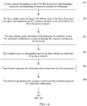
- An embodiment of the present invention provides a CQI measurement method. As shown in FIG. 1A and FIG. 1B , the method includes the following steps.
- a base station determines a target CSI-RS on each of time-frequency resources corresponding to resource numbers of a terminal.
- the target CSI-RS is a precoded CSI-RS
- the time-frequency resource is a resource element used to transmit the CSI-RS or the target CSI-RS.
- the target CSI-RS may be a CSI-RS obtained after a CSI-RS corresponding to the resource number is precoded by using a precoding matrix corresponding to the terminal.
- the precoding matrix corresponding to the terminal may be determined by the base station.
- the CSI-RS corresponding to the resource number may be a preset CSI-RS, or may be a CSI-RS determined by the base station in another manner.
- the CSI-RS is well known to the base station and the terminal.
- the resource number is a target CSI-RS port number, a row number of an orthogonal matrix, or a column number of an orthogonal matrix, a combination of N resource elements and one code whose length is N is corresponding to one target CSI-RS port or one resource element is corresponding to one target CSI-RS port, and N is an integer greater than or equal to 2.
- the target CSI-RS port number is a number of a target CSI-RS port, and numbers of target CSI-RS ports are used to distinguish between different target CSI-RS ports.
- the resource number when the resource number is a target CSI-RS port number, the resource number may indicate both a time domain resource and a code domain resource; and when the resource number is a row (or column) number of an orthogonal matrix, the base station may preset different time-frequency resources for different resource numbers, or time-frequency resources corresponding to different resource numbers are same time domain resources.
- a basic unit for air interface resource allocation in an LTE system and an LTE-Advanced system is a physical resource block (Physical Resource Block, PRB for short).
- PRB Physical Resource Block
- One PRB includes 12 consecutive subcarriers in frequency domain, and includes seven consecutive orthogonal frequency division multiplexing (Orthogonal Frequency Division Multiplexing, OFDM for short) symbol periods in time domain.
- a resource including one OFDM symbol period and one subcarrier is referred to as one resource element (Resource Element, RE for short).
- RE resource element
- some REs are used to transmit data, and some REs are used to transmit a reference signal.
- a resource element 1 (referred to as an RE 1 in the following), a resource element 2 (referred to as an RE 2 in the following), a resource element 3 (referred to as an RE 3 in the following), and a resource element 4 (referred to as an RE 4 in the following) shown in FIG. 2 each are used to transmit a reference signal.
- the resource number may be a target CSI-RS port number.
- one CSI-RS port may occupy two REs (or four REs).
- the resource number may be a combination of two (or four) REs and an orthogonal code whose length is 2 (or 4).
- a case for a target CSI-RS port is similar to this. For example, based on the example described in FIG.
- a target CSI-RS port whose number is 1 may be corresponding to the RE 1 and the RE 2, and use an orthogonal code whose number is a1 in a predefined group of orthogonal codes;
- a target CSI-RS port whose number is 2 may be corresponding to the RE 1 and the RE 2, and use an orthogonal code whose number is a2 in the predefined group of orthogonal codes;
- a target CSI-RS port whose number is 3 may be corresponding to the RE 3 and the RE 4, and use the orthogonal code whose number is a1 in the predefined group of orthogonal codes;
- a target CSI-RS port whose number is 4 may be corresponding to the RE 3 and the RE 4, and use the orthogonal code whose number is a2 in the predefined group of orthogonal codes.
- the resource number may be a row (or column) number of an orthogonal matrix.
- the resource number is a row (or column) number of an orthogonal matrix
- any two rows (or columns) of elements of the orthogonal matrix are orthogonal.
- a plurality of rows (or columns) of elements of the orthogonal matrix may be corresponding to a same time-frequency resource, or time-frequency resources corresponding to a row (or column) of elements of the orthogonal matrix may be preset.
- time-frequency resources corresponding to the first column of the orthogonal matrix may be the RE 1, the RE 2, the RE 3, and the RE 4.
- a second column of the orthogonal matrix includes four elements, and time-frequency resources corresponding to the second column of the orthogonal matrix are also the RE 1, the RE 2, the RE 3, and the RE 4.
- the resource number may be a resource element number, a code number of an orthogonal code in a predefined group of orthogonal codes, or a row number or a column number of a predefined orthogonal matrix, or may be a combination of a resource element and a code number of an orthogonal code in a predefined group of orthogonal codes and/or a row (or column) number of a predefined orthogonal matrix.
- the resource number may be a resource element number.
- the resource number may be a resource element number of one or more resource elements in the resource element 1, the resource element 2, the resource element 3, and the resource element 4.
- Resource element numbers are used to distinguish between different resource elements.
- the resource number may be a code number of an orthogonal code in a predefined group of orthogonal codes.
- a plurality of orthogonal codes in the group of orthogonal codes may be corresponding to a same time-frequency resource, or a time-frequency resource corresponding to an orthogonal code with a specified code number may be preset.
- time-frequency resources corresponding to the orthogonal code with the code number A may be the RE 1, the RE 2, the RE 3, and the RE 4.
- An orthogonal code with a code number B includes four elements, and time-frequency resources corresponding to the orthogonal code with the code number B may also be the RE 1, the RE 2, the RE 3, and the RE 4.
- the time-frequency resource corresponding to the resource number is a time-frequency resource that can be indicated by the resource number.
- the resource number of the terminal may be obtained through allocation by the base station based a resource pool, and the resource pool is configured in both the terminal and the base station.
- the resource numbers are resource numbers of R resources included in a resource pool, one resource is corresponding to one resource number, and R is an integer greater than or equal to 2.
- the resource pool is a resource pool defined by the base station.
- the base station may send the resource pool to the terminal by using Radio Resource Control (Radio Resource Control, RRC for short) signaling.
- RRC Radio Resource Control
- the terminal may receive the resource pool by using the RRC signaling.
- the base station may indicate the resource pool to the terminal by using static/semi-static signaling (for example, the RRC signaling).
- the base station does not send data on a time-frequency resource corresponding to the resource number in the resource pool.
- the terminal After receiving the resource pool, the terminal considers that all resource numbers in the resource pool are allocated to one or more terminals, so that the terminal determines interference.
- step 101 may include: determining, by the base station based on the resource number, the CSI-RS corresponding to the resource number, and the precoding matrix, the target CSI-RS sent on each of the time-frequency resources corresponding to the resource numbers.
- a process of determining, by the base station based on the resource number, the CSI-RS corresponding to the resource number, and the precoding matrix, the target CSI-RS sent on each of the time-frequency resources corresponding to the resource numbers may be specifically implemented by using the following steps 301 to 303: 301.
- the base station determines a first rank and a precoding matrix of the terminal.
- a first rank and a precoding matrix that are determined by the base station and that are corresponding to each of the plurality of terminals that form MU-MIMO can make interference between the plurality of terminals relatively small.
- the base station allocates the resource numbers to the terminal based on the first rank, where a quantity of resource numbers is the same as a value of the first rank.
- the base station performs, by using a code corresponding to the resource number, spectrum spreading on a CSI-RS corresponding to the resource number; and precodes, by using the precoding matrix, each CSI-RS obtained after spectrum spreading, to obtain the target CSI-RS sent on each of the time-frequency resources corresponding to the resource numbers.
- the code corresponding to the resource number is a code whose length is N and that is corresponding to the target CSI-RS port; or when the resource number is a row number of an orthogonal matrix, the code corresponding to the resource number is a row element corresponding to the row number; or when the resource number is a column number of an orthogonal matrix, the code corresponding to the resource number is a column element corresponding to the column number.
- CSI-RSs transmitted by the base station on different PRBs may be different symbols or same symbols in a CSI-RS sequence.
- the first rank corresponding to the terminal is 1.
- a target CSI-RS port number allocated by the base station to the terminal is 1, based on the example described in FIG. 2 , the target CSI-RS port 1 is corresponding to two resource elements, the two resource elements are the RE 1 and the RE 2, and the target CSI-RS port 1 is also corresponding to a code whose length is 2.
- a CSI-RS on the RE 1 is a CSI-RS 1
- a CSI-RS on the RE 2 is a CSI-RS 2.
- the precoding matrix may be multiplied by the reference signal CSI-RS 1 on the RE 1 (a multiplication result is a target CSI-RS on the RE 1), and the base station transmits the multiplication result on the RE 1 by using an antenna port 1 and an antenna port 2; and the precoding matrix may be multiplied by the reference signal CSI-RS 2 on the RE 2 (a multiplication result is a target CSI-RS on the RE 2), and the base station transmits the multiplication result on the RE 2 by using the antenna port 1 and the antenna port 2.
- the CSI-RS 1 and the CSI-RS 2 are obtained after spectrum spreading is performed based on the CSI-RS, the CSI-RS 1 and the CSI-RS 2 are essentially different forms of the CSI-RS. It can be learned that the target CSI-RS is a result of multiplying the precoding matrix by the CSI-RS corresponding to the resource number, and data sent by the base station on the RE 1 and data sent by the base station on RE 2 are essentially different forms of the target CSI-RS.
- Example 1 merely shows an example process of determining, when the resource number is a target CSI-RS port number, the target CSI-RS corresponding to the resource number.
- the target CSI-RS may be determined by using a related method in the prior art.
- the base station sends the target CSI-RS on each of the time-frequency resources corresponding to the resource numbers to the terminal on the time-frequency resource.
- H 1 ⁇ CSI-RS1 is sent on the RE 1 by using the antenna port 1 of the base station
- H 1 ⁇ CSI-RS2 is sent on the RE 2 by using the antenna port 1 of the base station
- H 2 ⁇ CSI-RS1 is sent on the RE 1 by using the antenna port 2 of the base station
- H 2 ⁇ CSI-RS2 is sent on the RE 2 by using the antenna port 2 of the base station.
- the base station sends indication information to the terminal, where the indication information is used to indicate the resource numbers to the terminal.
- step 103 includes: sending, by the base station, the indication information to the terminal on a physical downlink control channel (Physical Downlink Control Channel, PDCCH for short), where resource numbers indicated by the indication information sent by the base station to the terminal on PDCCHs in different subframes are the same or different.
- a physical downlink control channel Physical Downlink Control Channel, PDCCH for short
- the terminal may quickly determine information sent by the base station on the PDCCH. Therefore, the base station may send the indication information in each subframe, so that the terminal measures channel quality based on a resource number allocated by the base station to the terminal.
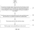
- the terminal receives information sent by the base station on each time-frequency resource.
- the terminal receives the indication information sent by the base station.
- step 105 includes: receiving, by the terminal on a PDCCH, the indication information sent by the base station, where resource numbers indicated by the indication information that is sent by the base station and that is received by the terminal on PDCCHs in different subframes are the same or different.
- the terminal determines the resource numbers of the terminal based on the indication information.
- the terminal determines target information from the information based on the resource number of the terminal, where the target information is received information that is sent by the base station to the terminal on the time-frequency resource corresponding to the resource number of the terminal.
- the target information includes information received on the RE 1 and information received on the RE 2.
- the information received on the RE 1 is obtained by superimposing H 1 ⁇ CSI-RS1 and H 2 ⁇ CSI-RS1 that are contaminated by a channel
- the information received on the RE 2 is obtained by superimposing H 1 ⁇ CSI-RS2 and H 2 ⁇ CSI-RS2 that are contaminated by a channel.
- step 107 includes: determining, by the terminal, the information received on the time-frequency resource corresponding to the resource number of the terminal; and despreading, by the terminal by using a code corresponding to the resource number of the terminal, the information received on the time-frequency resource corresponding to the resource number of the terminal, to obtain the target information.
- the base station performs, in the process of determining the target CSI-RS sent on each of the time-frequency resources corresponding to the resource numbers of the terminal, spectrum spreading on the CSI-RS corresponding to the resource number of the terminal, after the terminal receives the information on the time-frequency resource corresponding to the resource number of the terminal, the terminal needs to despread the information to obtain the target information.
- the terminal measures channel quality based on the target information, and determines a CQI based on the measured channel quality.
- the terminal needs to determine interference in a process of measuring the CQI based on the target information. Specifically, the terminal may subtract the target information from the information sent on each time-frequency resource, and consider remaining information as a sum of interference from a terminal other than the terminal in MU-MIMO and interference from a neighboring cell user.
- the terminal sends the CQI to the base station.
- the base station receives the CQI sent by the terminal.
- the CQI is used to indicate the channel quality.
- the base station dynamically indicates, to the terminal, the resource number allocated to the terminal.
- the terminal After receiving the resource number indicated by the base station, the terminal determines, based on the resource number, the target information from the information received on each time-frequency resource, measures the CQI based on the target information, and feeds back the CQI to the base station, instead of feeding back all measured CQIs to the base station after measuring the CQIs based on the information received on all time-frequency resources. Therefore, resource consumption of the terminal is greatly reduced.
- the method further includes the following steps:
- the modulation and coding policy sent by the base station to the terminal may be sent by using control signaling, and the data sent by the base station is data modulated and coded by using the modulation and coding policy.
- the sending, by the base station, the indication information to the terminal on a PDCCH includes: sending, by the base station, uplink scheduling indication information to the terminal, where the uplink scheduling indication information includes the indication information; or sending, by the base station, downlink scheduling indication information to the terminal, where the downlink scheduling indication information includes the indication information.
- the receiving, by the terminal on a PDCCH, the indication information sent by the base station includes: receiving, by the terminal, uplink scheduling indication information sent by the base station, where the uplink scheduling indication information includes the indication information; or receiving, by the terminal, downlink scheduling indication information sent by the base station, where the downlink scheduling indication information includes the indication information.
- the method further includes the following steps:
- bandwidth of the target CSI-RS is consistent with bandwidth of the data
- UE may measure the target CSI-RS and feed back the CQI within corresponding bandwidth, thereby reducing resource consumption for uplink feedback.
- the data resource allocation manner and the modulation and coding policy are delivered together on a control channel by using the downlink scheduling indication information.
- the base station may determine, based on a resource number allocated to a terminal, a time-frequency resource location at which a reference signal is sent to the terminal, and needs to determine a modulation and coding policy based on a CQI. Therefore, the data resource allocation manner and the indication information may be sent to the terminal on a PDCCH in one subframe, and after the modulation and coding policy of the terminal is determined, the modulation and coding policy is sent to the terminal on a PDCCH in another subframe.
- the method further includes: sending, by the base station, trigger information to the terminal, where the trigger information is used to trigger the terminal to measure the channel quality and/or a second rank based on the information received on each of the time-frequency resources corresponding to the resource numbers indicated by the indication information; receiving, by the terminal, the trigger information sent by the base station; and determining, by the terminal based on the trigger information, to measure the channel quality and/or the second rank.
- the second rank refer to the following description.
- the indication information may be included in the uplink scheduling indication information, or the trigger information (or the indication information) is included in the downlink scheduling indication information.
- the indication information and the trigger information may be included in a same message.
- the resource numbers are the resource numbers of the R resources included in the resource pool
- the indication information includes R bits, an r th bit in the R bits is used to indicate whether to allocate an r th resource in the R resources to the terminal, R is an integer greater than or equal to 2, and r is an integer greater than or equal to 1 and less than or equal to R; or the indication information includes 3 bits, and the resource numbers indicated by the indication information are different when values of the 3 bits are different; or the indication information includes 4 bits, and the resource numbers indicated by the indication information are different when values of the 4 bits are different.
- step 106 includes: determining, by the terminal, the resource numbers of the terminal based on R bits included in the indication information, where an r th bit in the R bits is used to indicate whether to allocate an r th resource in the R resources to the terminal, R is an integer greater than or equal to 2, and r is an integer greater than or equal to 1 and less than or equal to R; or determining, by the terminal, the resource numbers of the terminal based on values of 3 bits included in the indication information; or determining, by the terminal, the resource numbers of the terminal based on values of 4 bits included in the indication information.
- the four target CSI-RS ports may be indicated by using values of 4 bits.
- a bit i (i is an integer greater than or equal to 0 and less than or equal to 3) indicates an i th target CSI-RS port.
- 0001 represents a target CSI-RS port 0
- 0010 represents a target CSI-RS port 1
- 1010 represents a target CSI-RS port 3 and the target CSI-RS port 1. If the terminal determines that the 4 bits included in the indication information are 0101, the terminal determines that the resource numbers of the terminal are the target CSI-RS port 0 and a target CSI-RS port 2.
- a value of a bit when a value of a bit is 1, it indicates that the base station allocates a resource corresponding to the bit to the terminal. In actual implementation, when a value of a bit is 0, it may also indicate that the base station allocates a resource corresponding to the bit to the terminal.
- one of the R bits may be used to indicate whether to allocate one of the R resources to the terminal. Specifically, the base station (or the base station and the terminal) may determine that which bit is used to indicate which resource.
- the four target CSI-RS ports may be indicated by using values of 3 bits. Different values of the 3 bits are corresponding to different target CSI-RS port numbers. For a specific correspondence, refer to Table 1. 0, 1, 2, and 3 in a resource number column in Table 1 are port numbers of the four target CSI-RS ports. One port number is corresponding to one target CSI-RS port. Table 1 Value of 3 bits Resource number 0 0 1 1 2 2 3 3 4 0 and 1 5 2 and 3 6 0, 1, and 2 7 0, 1, 2, and 3
- the eight target CSI-RS ports may be indicated by using values of 4 bits. Different values of the 4 bits are corresponding to different target CSI-RS port numbers. For a specific correspondence, refer to Table 2. Digits 0 to 7 in a resource number column in Table 2 are port numbers of the eight target CSI-RS ports. One port number is corresponding to one target CSI-RS port.
- Table 2 Value of 4 bits Resource number 0 0 1 1 2 2 3 3 4 0 and 1 5 2 and 3 6 4 and 5 7 6 and 7 8 0, 1, and 2 9 3, 4, and 5 10 0, 1, 2, and 3 11 4, 5, 6, and 7 12 0, 1, 2, 3, and 4 13 0, 1, 2, 3, 4, and 5 14 0, 1, 2, 3, 4, 5, and 6 15 0, 1, 2, 3, 4, 5, 6, and 7
- the method further includes the following steps:
- the data port is a port obtained after an antenna port is weighted by using the precoding matrix.
- the data port is used to send data.
- a precoding matrix used for a target CSI-RS port of the terminal and a precoding matrix used to weight the antenna port are a same precoding matrix.
- the terminal when the terminal is one of a plurality of terminals that form MU-MIMO terminals, after the base station determines to form MU-MIMO by using the plurality of terminals, the base station redetermines a precoding matrix for each terminal, and consequently, CQIs reported by the terminals before the terminals form MU-MIMO are inaccurate. Therefore, each terminal needs to feed back a CQI again. However, because of a high correlation between a rank and a CQI, if the base station still sends data to the terminal based on the first rank after the CQI changes, the terminal may not correctly decode the data.
- the terminal further determines the second rank based on the target information, and feeds back the RI to the base station.
- the base station finally determines the second rank as a rank corresponding to the terminal, thereby ensuring that the terminal can correctly decode the data.
- the base station still sends data by using data ports whose quantity is the same as the value of the first rank, and the precoding matrix used for the data port is the same as the precoding matrix used for the target CSI-RS port. In this way, stability of interference between the plurality of terminals can be ensured.
- the terminal may determine a first RI based on a quantity of resource numbers indicated by the indication information, and the quantity of resource numbers is a value of the first RI.
- the terminal when the terminal measures the second rank based on the target information, and when the value of the first rank is 1 (in other words, the quantity of resource numbers indicated by the indication information is 1), because a minimum value of a rank corresponding to the terminal is 1, after the terminal receives the indication information, the terminal may determine only the CQI based on the target information, and does not redetermine the second rank.
- the terminal may sequentially determine CQIs corresponding to different values of the rank (a value of the rank is an integer greater than or equal to 1) whose maximum value is the value of the first rank, finally select, as the second rank, a rank corresponding to a maximum throughput rate, and feed back an RI and a CQI that are corresponding to the second rank to the base station.
- Scenario 1 The quantity of resource numbers allocated by the base station to the terminal is 2.
- y 0 k y 1 k x 0 i x 1 i
- the terminal calculates, based on this assumption, a CQI corresponding to each data stream.
- x (0) ( i ) represents an i th data symbol in a first data stream
- x (1) ( i ) represents an i th data symbol in a second data stream
- y (0) ( k ) represents a k th data symbol sent on a first data port
- y (1) ( k ) represents a k th data symbol sent on a second data port
- both i and k are integers greater than or equal to 0.
- the terminal calculates, based on this assumption, a CQI corresponding to the data stream.
- x ( p ) represents a p th data symbol in the data stream, and p is equal to 2i or 2i+1;
- y (0) ( q ) represents a q th data symbol sent on a first data port;
- y (1) ( q ) represents a q th data symbol sent on a second data port, and q is equal to 2k or 2k+1; and both i and k are integers greater than or equal to 0.
- Scenario 2 The quantity of resource numbers allocated by the base station to the terminal is 3.
- the terminal calculates, based on this assumption, a CQI corresponding to each data stream.
- x (0) (2 i ) represents a (2i) th data symbol in the first data stream
- x (1) ( i ) represents an i th data symbol in the second data stream
- x (0) (2 i +1) represents a (2i+1) th data symbol in the first data stream
- y ( p ) ( k ) represents a k th data symbol sent on a (p+1) th data port
- p is 0, 1, or 2
- both i and k are integers greater than or equal to 0.
- the terminal calculates, based on this assumption, CQIs corresponding to the two data streams.
- x ( p ) (2 i ) represents a (2i) th data symbol in a (p+1) th data stream
- x ( p ) (2 i +1) represents a (2i+1) th data symbol in the (p+1) th data stream
- p is 0 or 1
- y ( q ) (2 k ) represents a (2k) th data symbol sent on a (q+1) th data port
- y ( q ) (2 k +1) represents a (2k+1) th data symbol sent on the (q+1) th data port
- q is 0, 1, or 2
- i is an integer greater than or equal to 0.
- the terminal calculates, based on this assumption, a CQI corresponding to the data stream.
- x ( p ) represents a p th data symbol in the data stream, and p is 3i, 3i+1, or 3i+2;
- y (0) ( q ) represents a q th data symbol sent on a first data port, y (1) ( q ) represents a q th data symbol sent on a second data port, y (2) ( q ) represents a q th data symbol sent on a third data port, q is 3k, 3k+1, or 3k+2, and both i and k are integers greater than or equal to 0.
- Scenario 3 The quantity of resource numbers allocated by the base station to the terminal is 4.
- the terminal calculates, based on this assumption, CQIs corresponding to the two data streams.
- x (0) ( p ) represents a p th data symbol in the first data stream
- x (1) ( p ) represents a p th data symbol in the second data stream
- p is 2i or 2i+1
- y ( q ) ( k ) represents a k th data symbol sent on a (q+1) th data port, q is 0, 1, 2, or 3, and both i and k are integers greater than or equal to 0.
- a first data stream is separately transmitted on a first data port and a second data port
- the terminal calculates, based on this assumption, CQIs corresponding to the two data streams.
- x (0) ( p ) represents a p th data symbol in the first data stream
- x (1) ( p ) represents a p th data symbol in the second data stream
- p is 2i or 2i+1
- y ( q ) (2 k ) represents a (2k) th data symbol sent on a (q+1) th data port
- y (2) +1) represents a (2k+1) th data symbol sent on the third data port
- y (3) (2 k +1) represents a (2k+1) th data symbol sent on the fourth data port
- q is 0, 1, 2, or 3
- both i and k are integers greater than or equal to 0.
- a first data stream is separately and alternately transmitted on a first data port and a second data port
- the terminal calculates, based on this assumption, CQIs corresponding to the two data streams.
- x (0) ( p ) represents a p th data symbol in the first data stream
- x (1) ( p ) represents a p th data symbol in the second data stream
- p is 2i or 2i+1
- y ( q ) (2 k ) represents a (2k) th data symbol sent on a (q+1) th data port
- y ( q ) (2 k +1) represents a (2k+1) th data symbol sent on the (q+1) th data port
- q is 0, 1, 2, or 3
- both i and k are integers greater than or equal to 0.
- the terminal calculates, based on this assumption, a CQI corresponding to the data stream.
- x ( p ) represents a p th data symbol in the data stream, and p is 4i, 4i+1, 4i+2, or 4i+3;
- y (0) ( q ) represents a q th data symbol sent on a first data port, y (1) ( q ) represents a q th data symbol sent on a second data port, y (2) ( q ) represents a q th data symbol sent on a third data port, y (3) ( q ) represents a q th data symbol sent on a fourth data port, q is 4k, 4k+1, 4k+2, or 4k+3, and both i and k are integers greater than or equal to 0.
- the terminal calculates, based on this assumption, a CQI corresponding to the data stream.
- x ( p ) represents a p th data symbol in the data stream, and p is 4i, 4i+1, 4i+2, or 4i+3;
- y (0) ( q ) represents a q th data symbol sent on a first data port, y (1) ( q ) represents a q th data symbol sent on a second data port, y (2) ( q ) represents a q th data symbol q sent on a third data port, y (3) ( q ) represents a q th data symbol sent on a fourth data port, q is 4k, 4k+1, 4k+2, or 4k+3, and both i and k are integers greater than or equal to 0.
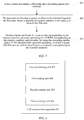
- An embodiment of the present invention further provides a CQI measurement apparatus 40.
- the apparatus 40 includes:
- the second sending unit 403 is specifically configured to: send the indication information to the terminal on a PDCCH, where resource numbers indicated by the indication information sent by the second sending unit 403 to the terminal on PDCCHs in different subframes are the same or different.
- the apparatus 40 further includes a second receiving unit 405, a second determining unit 406, a precoding unit 407, and a third sending unit 408.
- the second receiving unit 405 is configured to receive an RI sent by the terminal.
- the RI is an RI determined by the terminal based on a second rank that is measured by the terminal based on information received on each of the time-frequency resources corresponding to the resource numbers indicated by the indication information.
- the second determining unit 406 is configured to determine the second rank based on the RI.
- the precoding unit 407 is configured to precode, by using a precoding matrix corresponding to the terminal, a data stream sent to the terminal.
- the third sending unit 408 is configured to send the data stream on a data port.
- a quantity of data ports is the same as a value of a first rank
- a layer quantity of the data stream is the same as a value of the second rank
- the second rank is less than or equal to the first rank
- the first rank is an initial rank determined by a base station for the terminal.
- the apparatus 40 further includes a fourth sending unit 409.
- the fourth sending unit 409 is configured to send a resource pool to the terminal by using RRC signaling.
- the resource numbers are resource numbers of R resources included in the resource pool, one resource is corresponding to one resource number, and R is an integer greater than or equal to 2.
- the resource number is a target CSI-RS port number, a row number of an orthogonal matrix, or a column number of an orthogonal matrix, a combination of N resource elements and one code whose length is N is corresponding to one target CSI-RS port or one resource element is corresponding to one target CSI-RS port, and N is an integer greater than or equal to 2.
- the first determining unit 401 is specifically configured to: determine, based on the resource number, a CSI-RS corresponding to the resource number, and the precoding matrix, the target CSI-RS sent on each of the time-frequency resources corresponding to the resource numbers.
- the first determining unit 401 is specifically configured to:
- the code corresponding to the resource number is a code whose length is N and that is corresponding to the target CSI-RS port; or when the resource number is a row number of an orthogonal matrix, the code corresponding to the resource number is a row element corresponding to the row number; or when the resource number is a column number of an orthogonal matrix, the code corresponding to the resource number is a column element corresponding to the column number.
- the resource numbers are the resource numbers of the R resources included in the resource pool
- the indication information includes R bits, an r th bit in the R bits is used to indicate whether to allocate an r th resource in the R resources to the terminal, R is an integer greater than or equal to 2, and r is an integer greater than or equal to 1 and less than or equal to R; or the indication information includes 3 bits, and the resource numbers indicated by the indication information are different when values of the 3 bits are different; or the indication information includes 4 bits, and the resource numbers indicated by the indication information are different when values of the 4 bits are different.
- the apparatus 40 further includes a fifth sending unit 410.
- the fifth sending unit 410 is configured to send trigger information to the terminal.
- the trigger information is used to trigger the terminal to measure the channel quality and/or the second rank based on the information received on each of the time-frequency resources corresponding to the resource numbers indicated by the indication information.
- the second sending unit 403 is specifically configured to:
- the apparatus 40 further includes a sixth sending unit 411, configured to:
- the apparatus provided in this embodiment of the present invention may dynamically indicate, to the terminal, the resource number allocated to the terminal. After receiving the resource number indicated by the base station, the terminal determines, based on the resource number, the target information from the information received on each time-frequency resource, measures the CQI based on the target information, and feeds back the CQI to the base station, instead of feeding back all measured CQIs to the base station after measuring the CQIs based on the information received on all time-frequency resources. Therefore, resource consumption of the terminal is greatly reduced.
- each unit of the CQI measurement apparatus 40 may be built in or independent of a processor of the CQI measurement apparatus 40 in a form of hardware, or may be stored in a memory of the CQI measurement apparatus 40 in a form of software, so that the processor invokes and performs operations corresponding to the foregoing units.
- the processor may be a central processing unit (Central Processing Unit, CPU for short), an application-specific integrated circuit (Application Specific Integrated Circuit, ASIC for short), or one or more integrated circuits configured to implement this embodiment of the present invention.
- CPU Central Processing Unit
- ASIC Application Specific Integrated Circuit
- An embodiment of the present invention further provides a CQI measurement apparatus 60.
- the apparatus 60 includes a memory 601, a processor 602, a transmitter 603, and a receiver 604.
- the memory 601, the processor 602, the transmitter 603, and the receiver 604 are coupled together by using a bus system 605.
- the memory 601 may include a random access memory, and may further include a nonvolatile memory, for example, at least one magnetic disk memory.
- the bus system 605 may be an industry standard architecture (Industry Standard Architecture, ISA for short) bus, a peripheral component interconnect (Peripheral Component Interconnect, PCI for short) bus, an extended industry standard architecture (Extended Industry Standard Architecture, EISA for short) bus, or the like.
- the bus system 605 may be classified into an address bus, a data bus, a control bus, and the like. For ease of representation, only one thick line is used in FIG. 6 for representation, but it does not indicate that there is only one bus or one type of bus.
- the memory 601 is configured to store code, and the processor 602 performs the following actions based on the code: determining a target CSI-RS on each of time-frequency resources corresponding to resource numbers of a terminal, where the target CSI-RS is a precoded CSI-RS, and the time-frequency resource is a resource element used to transmit the CSI-RS or the target CSI-RS.
- the transmitter 603 is configured to send the target CSI-RS on each of the time-frequency resources corresponding to the resource numbers to the terminal on the time-frequency resource.
- the transmitter 603 is further configured to send indication information to the terminal.
- the indication information is used to indicate the resource numbers to the terminal.
- the receiver 604 is configured to receive a CQI sent by the terminal.
- the CQI is used to indicate channel quality.
- the transmitter 603 is specifically configured to: send the indication information to the terminal on a PDCCH, where resource numbers indicated by the indication information sent by the transmitter 603 to the terminal on PDCCHs in different subframes are the same or different.
- the receiver 604 is further configured to receive an RI sent by the terminal.
- the RI is an RI determined by the terminal based on a second rank that is measured by the terminal based on information received on each of the time-frequency resources corresponding to the resource numbers indicated by the indication information.
- the processor 602 is further configured to determine the second rank based on the RI.
- the processor 602 is further configured to precode, by using a precoding matrix corresponding to the terminal, a data stream sent to the terminal.
- the transmitter 603 is further configured to send the data stream on a data port.
- a quantity of data ports is the same as a value of a first rank
- a layer quantity of the data stream is the same as a value of the second rank
- the second rank is less than or equal to the first rank
- the first rank is an initial rank determined by a base station for the terminal.
- the transmitter 603 is further configured to: send a resource pool to the terminal by using RRC signaling, where the resource numbers are resource numbers of R resources included in the resource pool, one resource is corresponding to one resource number, and R is an integer greater than or equal to 2.
- the resource number is a target CSI-RS port number, a row number of an orthogonal matrix, or a column number of an orthogonal matrix, a combination of N resource elements and one code whose length is N is corresponding to one target CSI-RS port or one resource element is corresponding to one target CSI-RS port, and N is an integer greater than or equal to 2.
- the processor 602 is specifically configured to: determine, based on the resource number, a CSI-RS corresponding to the resource number, and the precoding matrix, the target CSI-RS sent on each of the time-frequency resources corresponding to the resource numbers.
- the processor 602 is specifically configured to:
- the code corresponding to the resource number is a code whose length is N and that is corresponding to the target CSI-RS port; or when the resource number is a row number of an orthogonal matrix, the code corresponding to the resource number is a row element corresponding to the row number; or when the resource number is a column number of an orthogonal matrix, the code corresponding to the resource number is a column element corresponding to the column number.
- the resource numbers are the resource numbers of the R resources included in the resource pool
- the indication information includes R bits, an r th bit in the R bits is used to indicate whether to allocate an r th resource in the R resources to the terminal, R is an integer greater than or equal to 2, and r is an integer greater than or equal to 1 and less than or equal to R; or the indication information includes 3 bits, and the resource numbers indicated by the indication information are different when values of the 3 bits are different; or the indication information includes 4 bits, and the resource numbers indicated by the indication information are different when values of the 4 bits are different.
- the transmitter 603 is further configured to: send trigger information to the terminal, where the trigger information is used to trigger the terminal to measure the channel quality and/or the second rank based on the information received on each of the time-frequency resources corresponding to the resource numbers indicated by the indication information.
- the transmitter 603 is specifically configured to:
- the transmitter 603 is further configured to:
- the apparatus provided in this embodiment of the present invention may dynamically indicate, to the terminal, the resource number allocated to the terminal. After receiving the resource number indicated by the base station, the terminal determines, based on the resource number, the target information from the information received on each time-frequency resource, measures the CQI based on the target information, and feeds back the CQI to the base station, instead of feeding back all measured CQIs to the base station after measuring the CQIs based on the information received on all time-frequency resources. Therefore, resource consumption of the terminal is greatly reduced.
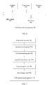
- An embodiment of the present invention further provides a CQI measurement apparatus 70.
- the apparatus 70 includes:
- the second receiving unit 702 is specifically configured to: receive, on a PDCCH, the indication information sent by the base station, where resource numbers indicated by the indication information that is sent by the base station and that is received by the second receiving unit 702 on PDCCHs in different subframes are the same or different.
- the apparatus 70 further includes a third determining unit 707, a second execution unit 708, and a second sending unit 709.
- the third determining unit 707 is configured to determine that a quantity of resource numbers is a value of a first rank.
- the first rank is an initial rank determined by the base station for the terminal.
- the second execution unit 708 is configured to: measure a second rank based on the target information and the first rank, and determine an RI based on the measured second rank.
- the second rank corresponding to the RI is less than or equal to the first rank.
- the second sending unit 709 is configured to send the RI to the base station.
- the apparatus 70 further includes a third receiving unit 710, configured to: receive, by using RRC signaling, a resource pool sent by the base station, where the resource numbers are resource numbers of R resources included in the resource pool, one resource is corresponding to one resource number, and R is an integer greater than or equal to 2.
- the resource number is a target CSI-RS port number, a row number of an orthogonal matrix, or a column number of an orthogonal matrix, a combination of N resource elements and one code whose length is N is corresponding to one target CSI-RS port or one resource element is corresponding to one target CSI-RS port, and N is an integer greater than or equal to 2.
- the second determining unit 704 is specifically configured to:
- the code corresponding to the resource number is a code whose length is N and that is corresponding to the target CSI-RS port; or when the resource number is a row number of an orthogonal matrix, the code corresponding to the resource number is a row element corresponding to the row number; or when the resource number is a column number of an orthogonal matrix, the code corresponding to the resource number is a column element corresponding to the column number.
- the first determining unit 703 is specifically configured to:
- the apparatus 70 further includes a fourth receiving unit 711 and a fourth determining unit 712.
- the fourth receiving unit 711 is configured to receive trigger information sent by the base station.
- the fourth determining unit 712 is configured to determine, based on the trigger information, to measure the channel quality and/or the second rank.
- the second receiving unit 702 is specifically configured to:
- the apparatus 70 further includes a measurement unit 713, configured to: measure, based on a received M th subframe sent by the base station, channel quality of data sent by the base station in an (M+K) th subframe.
- the M th subframe includes the indication information, the target CSI-RS, and a downlink data resource allocation manner
- the (M+K) th subframe includes a modulation and coding policy corresponding to the terminal
- a quantity and locations of PRBs allocated by the base station in the M th subframe to the target CSI-RS are the same as a quantity and locations of PRBs occupied by a data channel sent by the base station in the (M+K) th subframe
- both M and K are integers greater than or equal to 1.
- the apparatus provided in this embodiment of the present invention may receive the resource number indicated by the base station, determine, based on the resource number, the target information from the information received on each time-frequency resource, measure the CQI based on the target information, and feed back the CQI to the base station, instead of feeding back all measured CQIs to the base station after measuring the CQIs based on the information received on all time-frequency resources. Therefore, resource consumption of the terminal is greatly reduced.
- each unit of the CQI measurement apparatus 70 may be built in or independent of a processor of the CQI measurement apparatus 70 in a form of hardware, or may be stored in a memory of the CQI measurement apparatus 70 in a form of software, so that the processor invokes and performs operations corresponding to the foregoing units.
- the processor may be a CPU, an ASIC, or one or more integrated circuits configured to implement this embodiment of the present invention.
- An embodiment of the present invention further provides a CQI measurement apparatus 90.
- the apparatus 90 includes a receiver 901, a memory 902, a processor 903, and a transmitter 904.
- the receiver 901, the memory 902, the processor 903, and the transmitter 904 are coupled together by using a bus system 905.
- the memory 902 may include a random access memory, and may further include a nonvolatile memory, for example, at least one magnetic disk memory.
- the memory 902 may be an ISA bus, a PCI bus, an EISA bus, or the like.
- the memory 902 may be classified into an address bus, a data bus, a control bus, and the like. For ease of representation, only one thick line is used in FIG. 9 for representation, but it does not indicate that there is only one bus or one type of bus.
- the receiver 901 is configured to receive information sent by a base station on each time-frequency resource.
- the receiver 901 is further configured to receive indication information sent by the base station.
- the indication information is used to indicate resource numbers of a terminal to the terminal;
- the memory 902 is configured to store code, and the processor 903 performs the following actions based on the code:
- the transmitter 904 is configured to send the CQI to the base station.
- the receiver 901 is specifically configured to: receive, on a PDCCH, the indication information sent by the base station, where resource numbers indicated by the indication information that is sent by the base station and that is received by the receiver 901 on PDCCHs in different subframes are the same or different.
- the processor 903 is further configured to determine that a quantity of resource numbers is a value of a first rank.
- the first rank is an initial rank determined by the base station for the terminal.
- the processor 903 is further configured to: measure a second rank based on the target information and the first rank, and determine an RI based on the measured second rank.
- the second rank corresponding to the RI is less than or equal to the first rank.
- the transmitter 904 is further configured to send the RI to the base station.
- the receiver 901 is further configured to: receive, by using RRC signaling, a resource pool sent by the base station, where the resource numbers are resource numbers of R resources included in the resource pool, one resource is corresponding to one resource number, and R is an integer greater than or equal to 2.
- the resource number is a target CSI-RS port number, a row number of an orthogonal matrix, or a column number of an orthogonal matrix, a combination of N resource elements and one code whose length is N is corresponding to one target CSI-RS port or one resource element is corresponding to one target CSI-RS port, and N is an integer greater than or equal to 2.
- the processor 903 is specifically configured to:
- the code corresponding to the resource number is a code whose length is N and that is corresponding to the target CSI-RS port; or when the resource number is a row number of an orthogonal matrix, the code corresponding to the resource number is a row element corresponding to the row number; or when the resource number is a column number of an orthogonal matrix, the code corresponding to the resource number is a column element corresponding to the column number.
- the processor 903 is specifically configured to:
- the receiver 901 is further configured to receive trigger information sent by the base station; and the processor 903 is further configured to determine, based on the trigger information, to measure the channel quality and/or the second rank.
- the receiver 901 is specifically configured to:
- the processor 903 is further configured to: measure, based on a received M th subframe sent by the base station, channel quality of data sent by the base station in an (M+K) th subframe.
- the M th subframe includes the indication information, the target CSI-RS, and a downlink data resource allocation manner
- the (M+K) th subframe includes a modulation and coding policy corresponding to the terminal
- a quantity and locations of PRBs allocated by the base station in the M th subframe to the target CSI-RS are the same as a quantity and locations of PRBs occupied by a data channel sent by the base station in the (M+K) th subframe
- both M and K are integers greater than or equal to 1.
- the apparatus provided in this embodiment of the present invention may receive the resource number indicated by the base station, determine, based on the resource number, the target information from the information received on each time-frequency resource, measure the CQI based on the target information, and feed back the CQI to the base station, instead of feeding back all measured CQIs to the base station after measuring the CQIs based on the information received on all time-frequency resources. Therefore, resource consumption of the terminal is greatly reduced.
- the disclosed apparatus and method may be implemented in other manners.
- the described apparatus embodiment is merely an example.
- the module division is merely logical function division and may be other division in actual implementation.
- a plurality of modules or components may be combined or integrated into another system, or some features may be ignored or not performed.
- modules described as separate parts may or may not be physically separate, and parts displayed as modules may or may not be physical modules, may be located in one position, or may be distributed on a plurality of network units. Some or all of the units may be selected based on actual requirements to achieve the objectives of the solutions of the embodiments.
- modules in the embodiments of the present invention may be integrated into one processing module, or two or more modules may be integrated into one module.
- the integrated module may be implemented in a form of hardware, or may be implemented in a form of hardware in addition to a software functional module.
- the integrated module may be stored in a computer-readable storage medium.
- the software functional module is stored in a storage medium and includes several instructions for instructing a computer device (which may be a personal computer, a server, a network device, or the like) to perform some steps of the methods described in the embodiments of the present invention.
- the foregoing storage medium includes: any medium that can store program code, such as a USB flash drive, a removable hard disk, a read-only memory (Read-Only Memory, ROM for short), a random access memory (Random Access Memory, RAM for short), a magnetic disk, or an optical disc.
Landscapes
- Engineering & Computer Science (AREA)
- Computer Networks & Wireless Communication (AREA)
- Signal Processing (AREA)
- Quality & Reliability (AREA)
- Mobile Radio Communication Systems (AREA)
Abstract
Description
- The present invention relates to the field of communications technologies, and in particular, to a channel quality index (Channel Quality Index, CQI for short) measurement method and apparatus.
- A multiple-input multiple-output (Multiple Input Multiple Output, MIMO for short) technology is widely used in a Long Term Evolution (Long Term Evolution, LTE for short) system. In a MIMO system, a precoding technology is usually used to improve signal transmission quality/increase a signal transmission rate. In an LTE system in a frequency division multiplexing (Frequency Division Duplexing, FDD for short) mode, a terminal determines downlink channel information based on a received channel state information-reference signal (Channel State Information Reference Signal, CSI-RS for short) sent by a base station, and feeds back the downlink channel information to the base station. The downlink channel information includes a precoding matrix index (Precoding Matrix Index, PMI), a rank index (Rank Index, RI for short), and a CQI. Currently, the terminal determines the downlink channel information based on an assumption of single user MIMO (Single-User MIMO, SU-MIMO for short). After receiving downlink channel information sent by a plurality of terminals, if the base station determines to select the plurality of terminals to form multi-user MIMO (Multi-User MIMO, MU-MIMO for short), to reduce interference between the plurality of terminals, based on the downlink channel information fed back by each terminal and by using a preset algorithm (for example, a zero-forcing algorithm), the base station reconstructs a precoding matrix for the terminal, redetermines a rank (Rank) of a channel, and allocates a corresponding CSI-RS port to the terminal. Because a CQI fed back by the terminal is based on the assumption of SU-MIMO, the CQI does not match actual downlink channel quality in a MU-MIMO scenario.
- To resolve this problem, the base station precodes the CSI-RS based on the precoding matrix reconstructed for the terminal, and sends a precoded CSI-RS to the terminal. The terminal remeasures a CQI based on the CSI-RS, and feeds back the CQI to the base station. In this case, when remeasuring the CQI based on the CSI-RS, the base station needs to measure channel quality of a channel corresponding to each CSI-RS port (in other words, the terminal needs to measure, based on received information on a time-frequency resource corresponding to each CSI-RS port, channel quality of a channel corresponding to the CSI-RS port), and feed back channel quality of channels corresponding to all CSI-RS ports to the base station. However, actually, the base station needs only channel quality of a channel corresponding to a CSI-RS port corresponding to the terminal. Consequently, an uplink resource is wasted.
- Embodiments of the present invention provide a channel quality index measurement method and apparatus, to reduce resource consumption of a terminal.
- To achieve the foregoing objectives, the following technical solutions are used in the embodiments of the present invention:
- According to a first aspect, a CQI measurement method is provided. The method includes:
- determining, by a base station, a target CSI-RS on each of time-frequency resources corresponding to resource numbers of a terminal, where the target CSI-RS is a precoded CSI-RS, and the time-frequency resource is a resource element used to transmit the CSI-RS or the target CSI-RS;
- sending, by the base station, the target CSI-RS on each of the time-frequency resources corresponding to the resource numbers to the terminal on the time-frequency resource;
- sending, by the base station to the terminal, indication information used to indicate the resource numbers of the terminal; and
- receiving, by the base station, a CQI that is sent by the terminal and that is used to indicate channel quality.
- Optionally, the sending, by the base station to the terminal, indication information includes:
sending, by the base station, the indication information to the terminal on a PDCCH, where resource numbers indicated by the indication information sent by the base station to the terminal on PDCCHs in different subframes are the same or different. - The terminal may quickly determine information sent by the base station on the PDCCH. Therefore, the base station may send the indication information in each subframe, so that the terminal measures channel quality based on a resource number allocated by the base station to the terminal.
- Optionally, a quantity of resource numbers indicated by the indication information is the same as a value of a first rank, and the method further includes:
- receiving, by the base station, an RI sent by the terminal, where the RI is an RI determined by the terminal based on a second rank that is measured by the terminal based on information received on each of the time-frequency resources corresponding to the resource numbers indicated by the indication information;
- determining, by the base station, the second rank based on the RI; and
- precoding, by the base station by using a precoding matrix corresponding to the terminal, a data stream sent to the terminal, and sending the data stream on a data port, where a quantity of data ports is the same as the value of the first rank, a layer quantity of the data stream is the same as a value of the second rank, the second rank is less than or equal to the first rank, and the first rank is an initial rank determined by the base station for the terminal.
- Because of a high correlation between a rank and a CQI, after the terminal feeds back a CQI again, if the base station still sends data to the terminal based on the first rank, the terminal may not correctly decode the data. Therefore, the terminal determines the second rank based on target information, and feeds back the RI to the base station. The base station finally determines the second rank as a rank corresponding to the terminal, thereby ensuring that the terminal can correctly decode the data.
- Optionally, the resource numbers are resource numbers of R resources included in a resource pool, one resource is corresponding to one resource number, R is an integer greater than or equal to 2, and the resource pool is a resource pool defined by the base station, and the method further includes:
sending, by the base station, the resource pool to the terminal by using RRC signaling. - Optionally, the resource number is a target CSI-RS port number, a row number of an orthogonal matrix, or a column number of an orthogonal matrix, a combination of N resource elements and one code whose length is N is corresponding to one target CSI-RS port or one resource element is corresponding to one target CSI-RS port, and N is an integer greater than or equal to 2.
- Optionally, the determining, by a base station, a target CSI-RS on each of time-frequency resources corresponding to resource numbers of a terminal includes:
- determining, by the base station based on the resource number, a CSI-RS corresponding to the resource number, and the precoding matrix, the target CSI-RS sent on each of the time-frequency resources corresponding to the resource numbers.
- Optionally, the determining, by the base station based on the resource number, a CSI-RS corresponding to the resource number, and the precoding matrix, the target CSI-RS sent on each of the time-frequency resources corresponding to the resource numbers includes:
- determining, by the base station, the first rank and the precoding matrix of the terminal;
- allocating, by the base station, the resource numbers to the terminal based on the first rank, where the quantity of resource numbers is the same as the value of the first rank; and
- performing, by the base station by using a code corresponding to the resource number, spectrum spreading on the CSI-RS corresponding to the resource number; and precoding, by using the precoding matrix, each CSI-RS obtained after spectrum spreading, to obtain the target CSI-RS sent on each of the time-frequency resources corresponding to the resource numbers, where
- when the resource number is a target CSI-RS port number, the code corresponding to the resource number is a code whose length is N and that is corresponding to the target CSI-RS port; or when the resource number is a row number of an orthogonal matrix, the code corresponding to the resource number is a row element corresponding to the row number; or when the resource number is a column number of an orthogonal matrix, the code corresponding to the resource number is a column element corresponding to the column number.
- Optionally, the resource numbers are the resource numbers of the R resources included in the resource pool, the indication information includes R bits, an rth bit in the R bits is used to indicate whether to allocate an rth resource in the R resources to the terminal, R is an integer greater than or equal to 2, and r is an integer greater than or equal to 1 and less than or equal to R; or the indication information includes 3 bits, and the resource numbers indicated by the indication information are different when values of the 3 bits are different; or the indication information includes 4 bits, and the resource numbers indicated by the indication information are different when values of the 4 bits are different.
- According to a second aspect, a CQI measurement method is provided. The method includes:
- receiving, by a terminal, information sent by a base station on each time-frequency resource;
- receiving, by the terminal, indication information that is sent by the base station and that is used to indicate resource numbers of the terminal to the terminal;
- determining, by the terminal, the resource numbers of the terminal based on the indication information;
- determining, by the terminal, target information from the information based on the resource number of the terminal, where the target information is received information that is sent by the base station to the terminal on a time-frequency resource corresponding to the resource number of the terminal, the time-frequency resource is a resource element used to transmit a CSI-RS or a target CSI-RS, and the target CSI-RS is a precoded CSI-RS;
- measuring, by the terminal, channel quality based on the target information, and determining a CQI based on the measured channel quality; and
- sending, by the terminal, the CQI to the base station.
- Optionally, the receiving, by the terminal, indication information sent by the base station includes:
receiving, by the terminal on a PDCCH, the indication information sent by the base station, where resource numbers indicated by the indication information that is sent by the base station and that is received by the terminal on PDCCHs in different subframes are the same or different. - The terminal may quickly determine information sent by the base station on the PDCCH. Therefore, the base station may send the indication information in each subframe, so that the terminal measures channel quality based on a resource number allocated by the base station to the terminal.
- Optionally, a quantity of resource numbers indicated by the indication information is the same as a value of a first rank, and after the determining, by the terminal, the resource numbers of the terminal based on the indication information, the method further includes:
- determining, by the terminal, that the quantity of resource numbers is the value of the first rank, where the first rank is an initial rank determined by the base station for the terminal;
- measuring, by the terminal, a second rank based on the target information and the first rank, and determining an RI based on the measured second rank, where the second rank corresponding to the RI is less than or equal to the first rank; and
- sending, by the terminal, the RI to the base station.
- Because of a high correlation between a rank and a CQI, after the terminal feeds back a CQI again, if the base station still sends data to the terminal based on the first rank, the terminal may not correctly decode the data. Therefore, the terminal determines the second rank based on the target information, and feeds back the RI to the base station. The base station finally determines the second rank as a rank corresponding to the terminal, thereby ensuring that the terminal can correctly decode the data.
- Optionally, the resource numbers are resource numbers of R resources included in a resource pool, one resource is corresponding to one resource number, and R is an integer greater than or equal to 2, and the method further includes:
receiving, by the terminal by using RRC signaling, the resource pool sent by the base station. - Optionally, the resource number is a target CSI-RS port number, a row number of an orthogonal matrix, or a column number of an orthogonal matrix, a combination of N resource elements and one code whose length is N is corresponding to one target CSI-RS port or one resource element is corresponding to one target CSI-RS port, and N is an integer greater than or equal to 2.
- Optionally, the determining, by the terminal, target information from the information based on the resource number of the terminal includes:
- determining, by the terminal, the information received on the time-frequency resource corresponding to the resource number of the terminal; and
- despreading, by the terminal by using a code corresponding to the resource number of the terminal, the information received on the time-frequency resource corresponding to the resource number of the terminal, to obtain the target information, where
- when the resource number is a target CSI-RS port number, the code corresponding to the resource number is a code whose length is N and that is corresponding to the target CSI-RS port; or when the resource number is a row number of an orthogonal matrix, the code corresponding to the resource number is a row element corresponding to the row number; or when the resource number is a column number of an orthogonal matrix, the code corresponding to the resource number is a column element corresponding to the column number.
- Optionally, the resource numbers are the resource numbers of the R resources included in the resource pool, and the determining, by the terminal, the resource numbers of the terminal based on the indication information includes:
- determining, by the terminal, the resource numbers of the terminal based on R bits included in the indication information, where an rth bit in the R bits is used to indicate whether to allocate an rth resource in the R resources to the terminal, R is an integer greater than or equal to 2, and r is an integer greater than or equal to 1 and less than or equal to R; or
- determining, by the terminal, the resource numbers of the terminal based on values of 3 bits included in the indication information; or
- determining, by the terminal, the resource numbers of the terminal based on values of 4 bits included in the indication information.
- According to a third aspect, a CQI measurement apparatus is provided. The apparatus includes:
- a first determining unit, configured to determine a target CSI-RS on each of time-frequency resources corresponding to resource numbers of a terminal, where the target CSI-RS is a precoded CSI-RS, and the time-frequency resource is a resource element used to transmit the CSI-RS or the target CSI-RS;
- a first sending unit, configured to send the target CSI-RS on each of the time-frequency resources corresponding to the resource numbers to the terminal on the time-frequency resource;
- a second sending unit, configured to send, to the terminal, indication information used to indicate the resource numbers of the terminal; and
- a first receiving unit, configured to receive a CQI that is sent by the terminal and that is used to indicate channel quality.
- Optionally, the second sending unit is specifically configured to:
send the indication information to the terminal on a PDCCH, where resource numbers indicated by the indication information sent by the second sending unit to the terminal on PDCCHs in different subframes are the same or different. - The terminal may quickly determine information sent by a base station on the PDCCH. Therefore, the base station may send the indication information in each subframe, so that the terminal measures channel quality based on a resource number allocated by the base station to the terminal.
- Optionally, the apparatus further includes a second receiving unit, a second determining unit, a precoding unit, and a third sending unit, where
- the second receiving unit is configured to receive an RI sent by the terminal, where the RI is an RI determined by the terminal based on a second rank that is measured by the terminal based on information received on each of the time-frequency resources corresponding to the resource numbers indicated by the indication information;
- the second determining unit is configured to determine the second rank based on the RI;
- the precoding unit is configured to precode, by using a precoding matrix corresponding to the terminal, a data stream sent to the terminal; and
- the third sending unit is configured to send the data stream on a data port, where a quantity of data ports is the same as a value of a first rank, a layer quantity of the data stream is the same as a value of the second rank, the second rank is less than or equal to the first rank, and the first rank is an initial rank determined by a base station for the terminal.
- Because of a high correlation between a rank and a CQI, after the terminal feeds back a CQI again, if the base station still sends data to the terminal based on the first rank, the terminal may not correctly decode the data. Therefore, the terminal determines the second rank based on target information, and feeds back the RI to the base station. The base station finally determines the second rank as a rank corresponding to the terminal, thereby ensuring that the terminal can correctly decode the data.
- Optionally, the apparatus further includes a fourth sending unit, where
the fourth sending unit is configured to send a resource pool to the terminal by using RRC signaling, where the resource numbers are resource numbers of R resources included in the resource pool, one resource is corresponding to one resource number, and R is an integer greater than or equal to 2. - Optionally, the resource number is a target CSI-RS port number, a row number of an orthogonal matrix, or a column number of an orthogonal matrix, a combination of N resource elements and one code whose length is N is corresponding to one target CSI-RS port or one resource element is corresponding to one target CSI-RS port, and N is an integer greater than or equal to 2.
- Optionally, the first determining unit is specifically configured to:
determine, based on the resource number, a CSI-RS corresponding to the resource number, and the precoding matrix, the target CSI-RS sent on each of the time-frequency resources corresponding to the resource numbers. - Optionally, the first determining unit is specifically configured to:
- determine the first rank and the precoding matrix of the terminal;
- allocate the resource numbers to the terminal based on the first rank, where a quantity of resource numbers is the same as the value of the first rank; and
- perform, by using a code corresponding to the resource number, spectrum spreading on the CSI-RS corresponding to the resource number; and precode, by using the precoding matrix, each CSI-RS obtained after spectrum spreading, to obtain the target CSI-RS sent on each of the time-frequency resources corresponding to the resource numbers, where
- when the resource number is a target CSI-RS port number, the code corresponding to the resource number is a code whose length is N and that is corresponding to the target CSI-RS port; or when the resource number is a row number of an orthogonal matrix, the code corresponding to the resource number is a row element corresponding to the row number; or when the resource number is a column number of an orthogonal matrix, the code corresponding to the resource number is a column element corresponding to the column number.
- Optionally, the resource numbers are the resource numbers of the R resources included in the resource pool, the indication information includes R bits, an rth bit in the R bits is used to indicate whether to allocate an rth resource in the R resources to the terminal, R is an integer greater than or equal to 2, and r is an integer greater than or equal to 1 and less than or equal to R; or the indication information includes 3 bits, and the resource numbers indicated by the indication information are different when values of the 3 bits are different; or the indication information includes 4 bits, and the resource numbers indicated by the indication information are different when values of the 4 bits are different.
- According to a fourth aspect, a CQI measurement apparatus is provided. The apparatus includes:
- a first receiving unit, configured to receive information sent by a base station on each time-frequency resource;
- a second receiving unit, configured to receive indication information that is sent by the base station and that is used to indicate resource numbers of a terminal to the terminal;
- a first determining unit, configured to determine the resource numbers of the terminal based on the indication information;
- a second determining unit, configured to determine target information from the information based on the resource number of the terminal, where the target information is received information that is sent by the base station to the terminal on a time-frequency resource corresponding to the resource number of the terminal, the time-frequency resource is a resource element used to transmit a CSI-RS or a target CSI-RS, and the target CSI-RS is a precoded CSI-RS;
- a first execution unit, configured to: measure channel quality based on the target information, and determine a CQI based on the measured channel quality; and
- a first sending unit, configured to send the CQI to the base station.
- Optionally, the second receiving unit is specifically configured to:
receive, on a PDCCH, the indication information sent by the base station, where resource numbers indicated by the indication information that is sent by the base station and that is received by the second receiving unit on PDCCHs in different subframes are the same or different. - The terminal may quickly determine information sent by the base station on the PDCCH. Therefore, the base station may send the indication information in each subframe, so that the terminal measures channel quality based on a resource number allocated by the base station to the terminal.
- Optionally, the apparatus further includes a third determining unit, a second execution unit, and a second sending unit, where
the third determining unit is configured to determine that a quantity of resource numbers is a value of a first rank, where the first rank is an initial rank determined by the base station for the terminal;
the second execution unit is configured to: measure a second rank based on the target information and the first rank, and determine an RI based on the measured second rank, where the second rank corresponding to the RI is less than or equal to the first rank; and
the second sending unit is configured to send the RI to the base station. - Because of a high correlation between a rank and a CQI, after the terminal feeds back a CQI again, if the base station still sends data to the terminal based on the first rank, the terminal may not correctly decode the data. Therefore, the terminal determines the second rank based on the target information, and feeds back the RI to the base station. The base station finally determines the second rank as a rank corresponding to the terminal, thereby ensuring that the terminal can correctly decode the data.
- Optionally, the apparatus further includes a third receiving unit, configured to:
receive, by using RRC signaling, a resource pool sent by the base station, where the resource numbers are resource numbers of R resources included in the resource pool, one resource is corresponding to one resource number, and R is an integer greater than or equal to 2. - Optionally, the resource number is a target CSI-RS port number, a row number of an orthogonal matrix, or a column number of an orthogonal matrix, a combination of N resource elements and one code whose length is N is corresponding to one target CSI-RS port or one resource element is corresponding to one target CSI-RS port, and N is an integer greater than or equal to 2.
- Optionally, the second determining unit is specifically configured to:
- determine the information received on the time-frequency resource corresponding to the resource number of the terminal; and
- despread, by using a code corresponding to the resource number of the terminal, the information received on the time-frequency resource corresponding to the resource number of the terminal, to obtain the target information, where
- when the resource number is a target CSI-RS port number, the code corresponding to the resource number is a code whose length is N and that is corresponding to the target CSI-RS port; or when the resource number is a row number of an orthogonal matrix, the code corresponding to the resource number is a row element corresponding to the row number; or when the resource number is a column number of an orthogonal matrix, the code corresponding to the resource number is a column element corresponding to the column number.
- Optionally, the first determining unit is specifically configured to:
- determine the resource numbers of the terminal based on R bits included in the indication information, where an rth bit in the R bits is used to indicate whether to allocate an rth resource in the R resources to the terminal, R is an integer greater than or equal to 2, and r is an integer greater than or equal to 1 and less than or equal to R; or
- determine the resource numbers of the terminal based on values of 3 bits included in the indication information; or
- determine the resource numbers of the terminal based on values of 4 bits included in the indication information.
- According to a fifth aspect, a CQI measurement apparatus is provided. The apparatus includes a memory, a processor, a transmitter, and a receiver, where
the memory is configured to store code, and the processor performs the following actions based on the code: - determining a target CSI-RS on each of time-frequency resources corresponding to resource numbers of a terminal, where the target CSI-RS is a precoded CSI-RS, and the time-frequency resource is a resource element used to transmit the CSI-RS or the target CSI-RS;
- the transmitter is configured to send the target CSI-RS on each of the time-frequency resources corresponding to the resource numbers to the terminal on the time-frequency resource;
- the transmitter is further configured to send, to the terminal, indication information used to indicate the resource numbers of the terminal; and
- the receiver is configured to receive a CQI that is sent by the terminal and that is used to indicate channel quality.
- Optionally, the transmitter is specifically configured to:
send the indication information to the terminal on a PDCCH, where resource numbers indicated by the indication information sent by the transmitter to the terminal on PDCCHs in different subframes are the same or different. - The terminal may quickly determine information sent by a base station on the PDCCH. Therefore, the base station may send the indication information in each subframe, so that the terminal measures channel quality based on a resource number allocated by the base station to the terminal.
- Optionally, the receiver is further configured to receive an RI sent by the terminal, where the RI is an RI determined by the terminal based on a second rank that is measured by the terminal based on information received on each of the time-frequency resources corresponding to the resource numbers indicated by the indication information;
the processor is further configured to determine the second rank based on the RI;
the processor is further configured to precode, by using a precoding matrix corresponding to the terminal, a data stream sent to the terminal; and
the transmitter is further configured to send the data stream on a data port, where a quantity of data ports is the same as a value of a first rank, a layer quantity of the data stream is the same as a value of the second rank, the second rank is less than or equal to the first rank, and the first rank is an initial rank determined by a base station for the terminal. - Because of a high correlation between a rank and a CQI, after the terminal feeds back a CQI again, if the base station still sends data to the terminal based on the first rank, the terminal may not correctly decode the data. Therefore, the terminal determines the second rank based on target information, and feeds back the RI to the base station. The base station finally determines the second rank as a rank corresponding to the terminal, thereby ensuring that the terminal can correctly decode the data.
- Optionally, the transmitter is further configured to:
send a resource pool to the terminal by using RRC signaling, where the resource numbers are resource numbers of R resources included in the resource pool, one resource is corresponding to one resource number, and R is an integer greater than or equal to 2. - Optionally, the resource number is a target CSI-RS port number, a row number of an orthogonal matrix, or a column number of an orthogonal matrix, a combination of N resource elements and one code whose length is N is corresponding to one target CSI-RS port or one resource element is corresponding to one target CSI-RS port, and N is an integer greater than or equal to 2.
- Optionally, the processor is specifically configured to:
determine, based on the resource number, a CSI-RS corresponding to the resource number, and the precoding matrix, the target CSI-RS sent on each of the time-frequency resources corresponding to the resource numbers. - Optionally, the processor is specifically configured to:
- determine the first rank and the precoding matrix of the terminal;
- allocate the resource numbers to the terminal based on the first rank, where a quantity of resource numbers is the same as the value of the first rank; and
- perform, by using a code corresponding to the resource number, spectrum spreading on the CSI-RS corresponding to the resource number; and precode, by using the precoding matrix, each CSI-RS obtained after spectrum spreading, to obtain the target CSI-RS sent on each of the time-frequency resources corresponding to the resource numbers, where
- when the resource number is a target CSI-RS port number, the code corresponding to the resource number is a code whose length is N and that is corresponding to the target CSI-RS port; or when the resource number is a row number of an orthogonal matrix, the code corresponding to the resource number is a row element corresponding to the row number; or when the resource number is a column number of an orthogonal matrix, the code corresponding to the resource number is a column element corresponding to the column number.
- Optionally, the resource numbers are the resource numbers of the R resources included in the resource pool, the indication information includes R bits, an rth bit in the R bits is used to indicate whether to allocate an rth resource in the R resources to the terminal, R is an integer greater than or equal to 2, and r is an integer greater than or equal to 1 and less than or equal to R; or the indication information includes 3 bits, and the resource numbers indicated by the indication information are different when values of the 3 bits are different; or the indication information includes 4 bits, and the resource numbers indicated by the indication information are different when values of the 4 bits are different.
- According to a sixth aspect, a CQI measurement apparatus is provided. The apparatus includes a receiver, a memory, a processor, and a transmitter, where
the receiver is configured to receive information sent by a base station on each time-frequency resource;
the receiver is further configured to receive indication information that is sent by the base station and that is used to indicate resource numbers of a terminal to the terminal;
the memory is configured to store code, and the processor performs the following actions based on the code: - determining the resource numbers of the terminal based on the indication information;
- determining target information from the information based on the resource number of the terminal, where the target information is received information that is sent by the base station to the terminal on a time-frequency resource corresponding to the resource number of the terminal, the time-frequency resource is a resource element used to transmit a CSI-RS or a target CSI-RS, and the target CSI-RS is a precoded CSI-RS;
- measuring channel quality based on the target information, and determining a CQI based on the measured channel quality; and
- the transmitter is configured to send the CQI to the base station.
- Optionally, the receiver is specifically configured to:
receive, on a PDCCH, the indication information sent by the base station, where resource numbers indicated by the indication information that is sent by the base station and that is received by the receiver on PDCCHs in different subframes are the same or different. - The terminal may quickly determine information sent by the base station on the PDCCH. Therefore, the base station may send the indication information in each subframe, so that the terminal measures channel quality based on a resource number allocated by the base station to the terminal.
- Optionally, the processor is further configured to determine that a quantity of resource numbers is a value of a first rank, where the first rank is an initial rank determined by the base station for the terminal;
the processor is further configured to: measure a second rank based on the target information and the first rank, and determine an RI based on the measured second rank, where the second rank corresponding to the RI is less than or equal to the first rank; and
the transmitter is further configured to send the RI to the base station. - Because of a high correlation between a rank and a CQI, after the terminal feeds back a CQI again, if the base station still sends data to the terminal based on the first rank, the terminal may not correctly decode the data. Therefore, the terminal determines the second rank based on the target information, and feeds back the RI to the base station. The base station finally determines the second rank as a rank corresponding to the terminal, thereby ensuring that the terminal can correctly decode the data.
- Optionally, the receiver is further configured to:
receive, by using RRC signaling, a resource pool sent by the base station, where the resource numbers are resource numbers of R resources included in the resource pool, one resource is corresponding to one resource number, and R is an integer greater than or equal to 2. - Optionally, the resource number is a target CSI-RS port number, a row number of an orthogonal matrix, or a column number of an orthogonal matrix, a combination of N resource elements and one code whose length is N is corresponding to one target CSI-RS port or one resource element is corresponding to one target CSI-RS port, and N is an integer greater than or equal to 2.
- Optionally, the processor is specifically configured to:
- determine the information received on the time-frequency resource corresponding to the resource number of the terminal; and
- despread, by using a code corresponding to the resource number of the terminal, the information received on the time-frequency resource corresponding to the resource number of the terminal, to obtain the target information, where
- when the resource number is a target CSI-RS port number, the code corresponding to the resource number is a code whose length is N and that is corresponding to the target CSI-RS port; or when the resource number is a row number of an orthogonal matrix, the code corresponding to the resource number is a row element corresponding to the row number; or when the resource number is a column number of an orthogonal matrix, the code corresponding to the resource number is a column element corresponding to the column number.
- Optionally, the processor is specifically configured to:
- determine the resource numbers of the terminal based on R bits included in the indication information, where an rth bit in the R bits is used to indicate whether to allocate an rth resource in the R resources to the terminal, R is an integer greater than or equal to 2, and r is an integer greater than or equal to 1 and less than or equal to R; or
- determine the resource numbers of the terminal based on values of 3 bits included in the indication information; or
- determine the resource numbers of the terminal based on values of 4 bits included in the indication information.
- According to the method and the apparatus provided in the embodiments of the present invention, the base station dynamically indicates, to the terminal, the resource number allocated to the terminal. After receiving the resource number indicated by the base station, the terminal determines, based on the resource number, the target information from the information received on each time-frequency resource, measures the CQI based on the target information, and feeds back the CQI to the base station, instead of feeding back all measured CQIs to the base station after measuring the CQIs based on the information received on all time-frequency resources. Therefore, resource consumption of the terminal is greatly reduced.
- To describe the technical solutions in the embodiments of the present invention or in the prior art more clearly, the following briefly describes the accompanying drawings required for describing the embodiments or the prior art. Apparently, the accompanying drawings in the following description show merely some embodiments of the present invention, and a person of ordinary skill in the art may still derive other drawings from these accompanying drawings without creative efforts.
-
FIG. 1A andFIG. 1B are a flowchart of a CQI measurement method according to an embodiment of the present invention; -
FIG. 2 is a schematic composition diagram of a PRB according to an embodiment of the present invention; -
FIG. 3 is a flowchart of a target CSI-RS determining method according to an embodiment of the present invention; -
FIG. 4 is a schematic composition diagram of a CQI measurement apparatus according to an embodiment of the present invention; -
FIG. 5 is a schematic composition diagram of another CQI measurement apparatus according to an embodiment of the present invention; -
FIG. 6 is a schematic composition diagram of another CQI measurement apparatus according to an embodiment of the present invention; -
FIG. 7 is a schematic composition diagram of another CQI measurement apparatus according to an embodiment of the present invention; -
FIG. 8 is a schematic composition diagram of another CQI measurement apparatus according to an embodiment of the present invention; and -
FIG. 9 is a schematic composition diagram of another CQI measurement apparatus according to an embodiment of the present invention. - The following clearly and completely describes the technical solutions in the embodiments of the present invention with reference to the accompanying drawings in the embodiments of the present invention. Apparently, the described embodiments are merely some but not all of the embodiments of the present invention. All other embodiments obtained by a person of ordinary skill in the art based on the embodiments of the present invention without creative efforts shall fall within the protection scope of the present invention.
- To make a person skilled in the art more clearly understand the technical solutions provided in the embodiments of the present invention, the prior art related to this application is first briefly described.
- In a MIMO scenario, a base station sends a CSI-RS corresponding to each of a plurality of terminals to the terminal. Each of the plurality of terminals receives the CSI-RS sent by the base station, performs channel estimation based on an assumption of SU-MIMO and the CSI-RS, and feeds back, to the base station, a PMI, an initial RI (to distinguish an RI from an RI in the following, the RI is referred to as the initial RI herein), and an initial CQI (to distinguish a CQI from a CQI in the following, the CQI is referred to as the initial CQI herein) that are obtained through estimation. After receiving PMIs, initial RIs, and initial CQIs that are sent by the plurality of terminals, the base station determines, based on a principle that a MIMO system has a maximum throughput or a minimum interference degree, whether to form MU-MIMO by using N terminals in the plurality of terminals. If yes, the base station redetermines, based on PMIs, initial RIs, and initial CQIs that are fed back by the N terminals and by using a principle of eliminating or reducing interference between the N terminals, a precoding matrix and a rank that are corresponding to each of the N terminals for the terminal. In this case, the rank is a first rank in the following. A method provided in the embodiments of the present invention may be applied to the scenario, and an example in which the method is applied to the scenario is used in the following for description. However, it should be noted that the method provided in the embodiments of the present invention may also be applied to another scenario. For example, when the base station determines not to form MU-MIMO, the method may still be applied between the base station and the terminal. Therefore, the terminal in the embodiments of the present invention may be any one of a plurality of terminals that form MU-MIMO, or may be another terminal.
- The method provided in the embodiments of the present invention is mainly applied to an LTE system and an LTE-Advanced system, and is mainly applied to a downlink MIMO scenario.
- An embodiment of the present invention provides a CQI measurement method. As shown in
FIG. 1A andFIG. 1B , the method includes the following steps. - 101. A base station determines a target CSI-RS on each of time-frequency resources corresponding to resource numbers of a terminal.
- The target CSI-RS is a precoded CSI-RS, and the time-frequency resource is a resource element used to transmit the CSI-RS or the target CSI-RS.
- Specifically, the target CSI-RS may be a CSI-RS obtained after a CSI-RS corresponding to the resource number is precoded by using a precoding matrix corresponding to the terminal. The precoding matrix corresponding to the terminal may be determined by the base station. The CSI-RS corresponding to the resource number may be a preset CSI-RS, or may be a CSI-RS determined by the base station in another manner. However, it should be noted that the CSI-RS is well known to the base station and the terminal.
- Optionally, the resource number is a target CSI-RS port number, a row number of an orthogonal matrix, or a column number of an orthogonal matrix, a combination of N resource elements and one code whose length is N is corresponding to one target CSI-RS port or one resource element is corresponding to one target CSI-RS port, and N is an integer greater than or equal to 2.
- The target CSI-RS port number is a number of a target CSI-RS port, and numbers of target CSI-RS ports are used to distinguish between different target CSI-RS ports.
- Because the combination of N resource elements and one code whose length is N is corresponding to one target CSI-RS port, when the resource number is a target CSI-RS port number, the resource number may indicate both a time domain resource and a code domain resource; and when the resource number is a row (or column) number of an orthogonal matrix, the base station may preset different time-frequency resources for different resource numbers, or time-frequency resources corresponding to different resource numbers are same time domain resources.
- It should be noted that as shown in
FIG. 2 , a basic unit for air interface resource allocation in an LTE system and an LTE-Advanced system is a physical resource block (Physical Resource Block, PRB for short). One PRB includes 12 consecutive subcarriers in frequency domain, and includes seven consecutive orthogonal frequency division multiplexing (Orthogonal Frequency Division Multiplexing, OFDM for short) symbol periods in time domain. A resource including one OFDM symbol period and one subcarrier is referred to as one resource element (Resource Element, RE for short). In a plurality of REs included in one PRB, some REs are used to transmit data, and some REs are used to transmit a reference signal. For example, a resource element 1 (referred to as anRE 1 in the following), a resource element 2 (referred to as anRE 2 in the following), a resource element 3 (referred to as anRE 3 in the following), and a resource element 4 (referred to as anRE 4 in the following) shown inFIG. 2 each are used to transmit a reference signal. - The resource number may be a target CSI-RS port number. For example, in LTE and LTE-Advance, one CSI-RS port may occupy two REs (or four REs). In this case, the resource number may be a combination of two (or four) REs and an orthogonal code whose length is 2 (or 4). A case for a target CSI-RS port is similar to this. For example, based on the example described in
FIG. 2 , if the base station has four target CSI-RS ports, a target CSI-RS port whose number is 1 may be corresponding to theRE 1 and theRE 2, and use an orthogonal code whose number is a1 in a predefined group of orthogonal codes; a target CSI-RS port whose number is 2 may be corresponding to theRE 1 and theRE 2, and use an orthogonal code whose number is a2 in the predefined group of orthogonal codes; a target CSI-RS port whose number is 3 may be corresponding to theRE 3 and theRE 4, and use the orthogonal code whose number is a1 in the predefined group of orthogonal codes; and a target CSI-RS port whose number is 4 may be corresponding to theRE 3 and theRE 4, and use the orthogonal code whose number is a2 in the predefined group of orthogonal codes. - The resource number may be a row (or column) number of an orthogonal matrix. When the resource number is a row (or column) number of an orthogonal matrix, any two rows (or columns) of elements of the orthogonal matrix are orthogonal. In this case, a plurality of rows (or columns) of elements of the orthogonal matrix may be corresponding to a same time-frequency resource, or time-frequency resources corresponding to a row (or column) of elements of the orthogonal matrix may be preset. As shown in
FIG. 2 , if a first column of the orthogonal matrix includes four elements, time-frequency resources corresponding to the first column of the orthogonal matrix may be theRE 1, theRE 2, theRE 3, and theRE 4. A second column of the orthogonal matrix includes four elements, and time-frequency resources corresponding to the second column of the orthogonal matrix are also theRE 1, theRE 2, theRE 3, and theRE 4. - In addition, the resource number may be a resource element number, a code number of an orthogonal code in a predefined group of orthogonal codes, or a row number or a column number of a predefined orthogonal matrix, or may be a combination of a resource element and a code number of an orthogonal code in a predefined group of orthogonal codes and/or a row (or column) number of a predefined orthogonal matrix.
- The resource number may be a resource element number. For example, the resource number may be a resource element number of one or more resource elements in the
resource element 1, theresource element 2, theresource element 3, and theresource element 4. Resource element numbers are used to distinguish between different resource elements. - The resource number may be a code number of an orthogonal code in a predefined group of orthogonal codes. In this case, a plurality of orthogonal codes in the group of orthogonal codes may be corresponding to a same time-frequency resource, or a time-frequency resource corresponding to an orthogonal code with a specified code number may be preset. Based on the example described in
FIG. 2 , if an orthogonal code with a code number A includes four elements, time-frequency resources corresponding to the orthogonal code with the code number A may be theRE 1, theRE 2, theRE 3, and theRE 4. An orthogonal code with a code number B includes four elements, and time-frequency resources corresponding to the orthogonal code with the code number B may also be theRE 1, theRE 2, theRE 3, and theRE 4. - It should be noted that the time-frequency resource corresponding to the resource number is a time-frequency resource that can be indicated by the resource number. The resource number of the terminal may be obtained through allocation by the base station based a resource pool, and the resource pool is configured in both the terminal and the base station.
- Optionally, the resource numbers are resource numbers of R resources included in a resource pool, one resource is corresponding to one resource number, and R is an integer greater than or equal to 2. The resource pool is a resource pool defined by the base station. The base station may send the resource pool to the terminal by using Radio Resource Control (Radio Resource Control, RRC for short) signaling. Correspondingly, the terminal may receive the resource pool by using the RRC signaling.
- Specifically, after defining the resource pool, the base station may indicate the resource pool to the terminal by using static/semi-static signaling (for example, the RRC signaling). The base station does not send data on a time-frequency resource corresponding to the resource number in the resource pool. After receiving the resource pool, the terminal considers that all resource numbers in the resource pool are allocated to one or more terminals, so that the terminal determines interference.
- Optionally, in specific implementation,
step 101 may include: determining, by the base station based on the resource number, the CSI-RS corresponding to the resource number, and the precoding matrix, the target CSI-RS sent on each of the time-frequency resources corresponding to the resource numbers. - Optionally, as shown in
FIG. 3 , a process of determining, by the base station based on the resource number, the CSI-RS corresponding to the resource number, and the precoding matrix, the target CSI-RS sent on each of the time-frequency resources corresponding to the resource numbers may be specifically implemented by using the followingsteps 301 to 303:
301. The base station determines a first rank and a precoding matrix of the terminal. - When the terminal is one of a plurality of terminals that form MU-MIMO, a first rank and a precoding matrix that are determined by the base station and that are corresponding to each of the plurality of terminals that form MU-MIMO can make interference between the plurality of terminals relatively small.
- 302. The base station allocates the resource numbers to the terminal based on the first rank, where a quantity of resource numbers is the same as a value of the first rank.
- 303. The base station performs, by using a code corresponding to the resource number, spectrum spreading on a CSI-RS corresponding to the resource number; and precodes, by using the precoding matrix, each CSI-RS obtained after spectrum spreading, to obtain the target CSI-RS sent on each of the time-frequency resources corresponding to the resource numbers.
- When the resource number is a target CSI-RS port number, the code corresponding to the resource number is a code whose length is N and that is corresponding to the target CSI-RS port; or when the resource number is a row number of an orthogonal matrix, the code corresponding to the resource number is a row element corresponding to the row number; or when the resource number is a column number of an orthogonal matrix, the code corresponding to the resource number is a column element corresponding to the column number.
- Specifically, CSI-RSs transmitted by the base station on different PRBs may be different symbols or same symbols in a CSI-RS sequence.
- In Example 1, the first rank corresponding to the terminal is 1. In this case, if a target CSI-RS port number allocated by the base station to the terminal is 1, based on the example described in
FIG. 2 , the target CSI-RS port 1 is corresponding to two resource elements, the two resource elements are theRE 1 and theRE 2, and the target CSI-RS port 1 is also corresponding to a code whose length is 2. After spectrum spreading is performed, by using the code whose length is 2, on the CSI-RS corresponding to the resource number, a CSI-RS on theRE 1 is a CSI-RS 1, and a CSI-RS on theRE 2 is a CSI-RS 2. If the base station has two antenna ports in total, and the precoding matrix corresponding to the terminal is
RS 1 on the RE 1 (a multiplication result is a target CSI-RS on the RE 1), and the base station transmits the multiplication result on theRE 1 by using anantenna port 1 and anantenna port 2; and the precoding matrix may be multiplied by the reference signal CSI-RS 2 on the RE 2 (a multiplication result is a target CSI-RS on the RE 2), and the base station transmits the multiplication result on theRE 2 by using theantenna port 1 and theantenna port 2. Because both the CSI-RS 1 and the CSI-RS 2 are obtained after spectrum spreading is performed based on the CSI-RS, the CSI-RS 1 and the CSI-RS 2 are essentially different forms of the CSI-RS. It can be learned that the target CSI-RS is a result of multiplying the precoding matrix by the CSI-RS corresponding to the resource number, and data sent by the base station on theRE 1 and data sent by the base station onRE 2 are essentially different forms of the target CSI-RS. - To help understand the full specification, Example 1 merely shows an example process of determining, when the resource number is a target CSI-RS port number, the target CSI-RS corresponding to the resource number. When the resource number is a row number or a column number of an orthogonal matrix, the target CSI-RS may be determined by using a related method in the prior art.
- 102. The base station sends the target CSI-RS on each of the time-frequency resources corresponding to the resource numbers to the terminal on the time-frequency resource.
- Specifically, based on Example 1, if the base station has two antenna ports, H 1·CSI-RS1 is sent on the
RE 1 by using theantenna port 1 of the base station, H 1·CSI-RS2 is sent on theRE 2 by using theantenna port 1 of the base station, H 2·CSI-RS1 is sent on theRE 1 by using theantenna port 2 of the base station, and H 2·CSI-RS2 is sent on theRE 2 by using theantenna port 2 of the base station. - 103. The base station sends indication information to the terminal, where the indication information is used to indicate the resource numbers to the terminal.
- Optionally, in specific implementation,
step 103 includes: sending, by the base station, the indication information to the terminal on a physical downlink control channel (Physical Downlink Control Channel, PDCCH for short), where resource numbers indicated by the indication information sent by the base station to the terminal on PDCCHs in different subframes are the same or different. - The terminal may quickly determine information sent by the base station on the PDCCH. Therefore, the base station may send the indication information in each subframe, so that the terminal measures channel quality based on a resource number allocated by the base station to the terminal.
- 104. The terminal receives information sent by the base station on each time-frequency resource.
- 105. The terminal receives the indication information sent by the base station.
- Optionally, in specific implementation,
step 105 includes: receiving, by the terminal on a PDCCH, the indication information sent by the base station, where resource numbers indicated by the indication information that is sent by the base station and that is received by the terminal on PDCCHs in different subframes are the same or different. - 106. The terminal determines the resource numbers of the terminal based on the indication information.
- 107. The terminal determines target information from the information based on the resource number of the terminal, where the target information is received information that is sent by the base station to the terminal on the time-frequency resource corresponding to the resource number of the terminal.
- Specifically, based on Example 1, the target information includes information received on the
RE 1 and information received on theRE 2. The information received on theRE 1 is obtained by superimposing H 1·CSI-RS1 and H 2·CSI-RS1 that are contaminated by a channel, and the information received on theRE 2 is obtained by superimposing H 1·CSI-RS2 and H 2·CSI-RS2 that are contaminated by a channel. - Optionally, in specific implementation,
step 107 includes: determining, by the terminal, the information received on the time-frequency resource corresponding to the resource number of the terminal; and despreading, by the terminal by using a code corresponding to the resource number of the terminal, the information received on the time-frequency resource corresponding to the resource number of the terminal, to obtain the target information. - For description of the code corresponding to the resource number, refer to the foregoing description.
- It should be noted that because the base station performs, in the process of determining the target CSI-RS sent on each of the time-frequency resources corresponding to the resource numbers of the terminal, spectrum spreading on the CSI-RS corresponding to the resource number of the terminal, after the terminal receives the information on the time-frequency resource corresponding to the resource number of the terminal, the terminal needs to despread the information to obtain the target information.
- 108. The terminal measures channel quality based on the target information, and determines a CQI based on the measured channel quality.
- The terminal needs to determine interference in a process of measuring the CQI based on the target information. Specifically, the terminal may subtract the target information from the information sent on each time-frequency resource, and consider remaining information as a sum of interference from a terminal other than the terminal in MU-MIMO and interference from a neighboring cell user.
- 109. The terminal sends the CQI to the base station.
- 110. The base station receives the CQI sent by the terminal.
- The CQI is used to indicate the channel quality.
- According to the method provided in this embodiment of the present invention, the base station dynamically indicates, to the terminal, the resource number allocated to the terminal. After receiving the resource number indicated by the base station, the terminal determines, based on the resource number, the target information from the information received on each time-frequency resource, measures the CQI based on the target information, and feeds back the CQI to the base station, instead of feeding back all measured CQIs to the base station after measuring the CQIs based on the information received on all time-frequency resources. Therefore, resource consumption of the terminal is greatly reduced.
- Optionally, after
step 110, the method further includes the following steps: - (11) The base station determines, based on the CQI, a modulation and coding policy corresponding to the terminal, and sends the modulation and coding policy to the terminal, and the terminal receives the modulation and coding policy sent by the base station.
- (12) The terminal determines, based on the modulation and coding policy, a demodulation and decoding policy used to demodulate and decode data sent by the base station.
- Specifically, for a method for determining the modulation and coding policy based on the CQI, refer to the prior art.
- The modulation and coding policy sent by the base station to the terminal may be sent by using control signaling, and the data sent by the base station is data modulated and coded by using the modulation and coding policy.
- Optionally, the sending, by the base station, the indication information to the terminal on a PDCCH includes: sending, by the base station, uplink scheduling indication information to the terminal, where the uplink scheduling indication information includes the indication information; or sending, by the base station, downlink scheduling indication information to the terminal, where the downlink scheduling indication information includes the indication information.
- Correspondingly, the receiving, by the terminal on a PDCCH, the indication information sent by the base station includes: receiving, by the terminal, uplink scheduling indication information sent by the base station, where the uplink scheduling indication information includes the indication information; or receiving, by the terminal, downlink scheduling indication information sent by the base station, where the downlink scheduling indication information includes the indication information.
- Optionally, when the downlink scheduling indication information includes the indication information, the method further includes the following steps:
- (21) The base station sends the indication information, the target CSI-RS, and a downlink data resource allocation manner to the terminal in an Mth subframe, so that the terminal measures channel quality of data sent by the base station in an (M+K)th subframe, where both M and K are integers greater than or equal to 1.
- (22) The base station sends, to the terminal, a modulation and coding policy corresponding to the terminal in the (M+K)th subframe, where a quantity and locations of physical resource blocks PRBs allocated by the base station in the Mth subframe to the target CSI-RS are the same as a quantity and locations of PRBs occupied by a data channel sent by the base station in the (M+K)th subframe.
- (23) The terminal measures, based on the received Mth subframe sent by the base station, the channel quality of the data sent by the base station in the (M+K)th subframe.
- In this optional method, bandwidth of the target CSI-RS is consistent with bandwidth of the data, and UE may measure the target CSI-RS and feed back the CQI within corresponding bandwidth, thereby reducing resource consumption for uplink feedback.
- In the prior art, the data resource allocation manner and the modulation and coding policy are delivered together on a control channel by using the downlink scheduling indication information. In this embodiment of the present invention, when the base station adds the indication information to the downlink scheduling indication information, the base station may determine, based on a resource number allocated to a terminal, a time-frequency resource location at which a reference signal is sent to the terminal, and needs to determine a modulation and coding policy based on a CQI. Therefore, the data resource allocation manner and the indication information may be sent to the terminal on a PDCCH in one subframe, and after the modulation and coding policy of the terminal is determined, the modulation and coding policy is sent to the terminal on a PDCCH in another subframe.
- Optionally, the method further includes: sending, by the base station, trigger information to the terminal, where the trigger information is used to trigger the terminal to measure the channel quality and/or a second rank based on the information received on each of the time-frequency resources corresponding to the resource numbers indicated by the indication information; receiving, by the terminal, the trigger information sent by the base station; and determining, by the terminal based on the trigger information, to measure the channel quality and/or the second rank. For description of the second rank, refer to the following description.
- It should be noted that the indication information (or the trigger information) may be included in the uplink scheduling indication information, or the trigger information (or the indication information) is included in the downlink scheduling indication information. Certainly, the indication information and the trigger information may be included in a same message.
- Optionally, the resource numbers are the resource numbers of the R resources included in the resource pool, the indication information includes R bits, an rth bit in the R bits is used to indicate whether to allocate an rth resource in the R resources to the terminal, R is an integer greater than or equal to 2, and r is an integer greater than or equal to 1 and less than or equal to R; or the indication information includes 3 bits, and the resource numbers indicated by the indication information are different when values of the 3 bits are different; or the indication information includes 4 bits, and the resource numbers indicated by the indication information are different when values of the 4 bits are different.
- Optionally, the resource numbers are the resource numbers of the R resources included in the resource pool, and in specific implementation,
step 106 includes:
determining, by the terminal, the resource numbers of the terminal based on R bits included in the indication information, where an rth bit in the R bits is used to indicate whether to allocate an rth resource in the R resources to the terminal, R is an integer greater than or equal to 2, and r is an integer greater than or equal to 1 and less than or equal to R; or determining, by the terminal, the resource numbers of the terminal based on values of 3 bits included in the indication information; or determining, by the terminal, the resource numbers of the terminal based on values of 4 bits included in the indication information. - For example, if the base station has four target CSI-RS ports, the four target CSI-RS ports may be indicated by using values of 4 bits. A bit i (i is an integer greater than or equal to 0 and less than or equal to 3) indicates an ith target CSI-RS port. 0001 represents a target CSI-RS port 0, 0010 represents a target CSI-
RS port 1, and 1010 represents a target CSI-RS port 3 and the target CSI-RS port 1. If the terminal determines that the 4 bits included in the indication information are 0101, the terminal determines that the resource numbers of the terminal are the target CSI-RS port 0 and a target CSI-RS port 2. - It should be noted that in this example, when a value of a bit is 1, it indicates that the base station allocates a resource corresponding to the bit to the terminal. In actual implementation, when a value of a bit is 0, it may also indicate that the base station allocates a resource corresponding to the bit to the terminal. In addition, one of the R bits may be used to indicate whether to allocate one of the R resources to the terminal. Specifically, the base station (or the base station and the terminal) may determine that which bit is used to indicate which resource.
- For example, if the base station has four target CSI-RS ports, the four target CSI-RS ports may be indicated by using values of 3 bits. Different values of the 3 bits are corresponding to different target CSI-RS port numbers. For a specific correspondence, refer to Table 1. 0, 1, 2, and 3 in a resource number column in Table 1 are port numbers of the four target CSI-RS ports. One port number is corresponding to one target CSI-RS port.
Table 1 Value of 3 bits Resource number 0 0 1 1 2 2 3 3 4 0 and 1 5 2 and 3 6 0, 1, and 2 7 0, 1, 2, and 3 - For example, if the base station has eight target CSI-RS ports, the eight target CSI-RS ports may be indicated by using values of 4 bits. Different values of the 4 bits are corresponding to different target CSI-RS port numbers. For a specific correspondence, refer to Table 2. Digits 0 to 7 in a resource number column in Table 2 are port numbers of the eight target CSI-RS ports. One port number is corresponding to one target CSI-RS port.
Table 2 Value of 4 bits Resource number 0 0 1 1 2 2 3 3 4 0 and 1 5 2 and 3 6 4 and 5 7 6 and 7 8 0, 1, and 2 9 3, 4, and 5 10 0, 1, 2, and 3 11 4, 5, 6, and 7 12 0, 1, 2, 3, and 4 13 0, 1, 2, 3, 4, and 5 14 0, 1, 2, 3, 4, 5, and 6 15 0, 1, 2, 3, 4, 5, 6, and 7 - Optionally, the method further includes the following steps:
- (31) The terminal determines that the quantity of resource numbers is the value of the first rank, where the first rank is an initial rank determined by the base station for the terminal.
- (32) The terminal measures a second rank based on the target information and the first rank, and determines an RI based on the measured second rank, where the second rank corresponding to the RI is less than or equal to the first rank.
- (33) The terminal sends the RI to the base station.
- (34) The base station receives the RI sent by the terminal.
- (35) The base station determines the second rank based on the RI.
- (36) The base station precodes, by using the precoding matrix corresponding to the terminal, a data stream sent to the terminal, and sends the data stream on a data port, where a quantity of data ports is the same as the value of the first rank, a layer quantity of the data stream is the same as a value of the second rank, and the second rank is less than or equal to the first rank.
- The data port is a port obtained after an antenna port is weighted by using the precoding matrix. The data port is used to send data. For a same terminal, a precoding matrix used for a target CSI-RS port of the terminal and a precoding matrix used to weight the antenna port are a same precoding matrix.
- In the foregoing method, when the terminal is one of a plurality of terminals that form MU-MIMO terminals, after the base station determines to form MU-MIMO by using the plurality of terminals, the base station redetermines a precoding matrix for each terminal, and consequently, CQIs reported by the terminals before the terminals form MU-MIMO are inaccurate. Therefore, each terminal needs to feed back a CQI again. However, because of a high correlation between a rank and a CQI, if the base station still sends data to the terminal based on the first rank after the CQI changes, the terminal may not correctly decode the data. Therefore, in this embodiment of the present invention, the terminal further determines the second rank based on the target information, and feeds back the RI to the base station. The base station finally determines the second rank as a rank corresponding to the terminal, thereby ensuring that the terminal can correctly decode the data. However, when sending the data stream to the terminal, the base station still sends data by using data ports whose quantity is the same as the value of the first rank, and the precoding matrix used for the data port is the same as the precoding matrix used for the target CSI-RS port. In this way, stability of interference between the plurality of terminals can be ensured.
- Specifically, the terminal may determine a first RI based on a quantity of resource numbers indicated by the indication information, and the quantity of resource numbers is a value of the first RI.
- In this case, when the terminal measures the second rank based on the target information, and when the value of the first rank is 1 (in other words, the quantity of resource numbers indicated by the indication information is 1), because a minimum value of a rank corresponding to the terminal is 1, after the terminal receives the indication information, the terminal may determine only the CQI based on the target information, and does not redetermine the second rank. When the value of the first rank is greater than 1 (in other words, the quantity of resource numbers indicated by the indication information is greater than 1), after the terminal receives the indication information, the terminal may sequentially determine CQIs corresponding to different values of the rank (a value of the rank is an integer greater than or equal to 1) whose maximum value is the value of the first rank, finally select, as the second rank, a rank corresponding to a maximum throughput rate, and feed back an RI and a CQI that are corresponding to the second rank to the base station.
- In the following plurality of scenarios, a method for determining, by the terminal, the second rank and a CQI that are corresponding to the RI is briefly described.
- Scenario 1: The quantity of resource numbers allocated by the base station to the terminal is 2. In this case, the terminal separately calculates CQIs when rank=2 and rank=1, and the terminal compares throughput rates measured when rank=2 and rank=1, and reports, to the base station, a rank (namely, the second rank) corresponding to a maximum throughput rate, and an RI and a CQI that are corresponding to the rank.

- The terminal calculates, based on this assumption, a CQI corresponding to each data stream. x (0)(i) represents an ith data symbol in a first data stream, x (1)(i) represents an ith data symbol in a second data stream, y (0)(k) represents a kth data symbol sent on a first data port, y (1)(k) represents a kth data symbol sent on a second data port, and both i and k are integers greater than or equal to 0.
- When the terminal calculates the CQI when rank=1, the terminal sends data in a transmit diversity manner defined in the LTE system. To be specific, assuming that the base station allocates one data stream to the terminal, data transmitted on two data ports is respectively:

- The terminal calculates, based on this assumption, a CQI corresponding to the data stream. x(p) represents a pth data symbol in the data stream, and p is equal to 2i or 2i+1; y (0)(q) represents a qth data symbol sent on a first data port; y (1)(q) represents a qth data symbol sent on a second data port, and q is equal to 2k or 2k+1; and both i and k are integers greater than or equal to 0.
- When the terminal calculates the CQI when rank=1, it may be assumed that a data stream is alternately sent on two data ports, namely:

- The terminal calculates, based on this assumption, a CQI corresponding to the data stream. x(p) represents a pth data symbol in the data stream, and p is equal to 2i or 2i+1; y (0)(q) represents a qth data symbol sent on a first data port; y (1)(q) represents a qth data symbol sent on a second data port, and q is equal to 2k or 2k+1; and both i and k are integers greater than or equal to 0.
- Scenario 2: The quantity of resource numbers allocated by the base station to the terminal is 3. In this case, the terminal separately calculates CQIs when rank=3, rank=2, and rank=1, and the terminal compares throughput rates measured when rank=3, rank=2, and rank=1, and reports, to the base station, a rank (namely, the second rank) corresponding to a maximum throughput rate, and an RI and a CQI that are corresponding to the rank.
- When the terminal calculates the CQI when rank=3, assuming that the base station allocates two data streams to the terminal, a first data stream is separately transmitted on a first data port and a second data port, and a second data stream is transmitted on a third data port, data sent by the base station on each data port is:

- The terminal calculates, based on this assumption, a CQI corresponding to each data stream. x (0)(2i) represents a (2i)th data symbol in the first data stream, x (1)(i) represents an ith data symbol in the second data stream, x (0)(2i+1) represents a (2i+1)th data symbol in the first data stream, y (p)(k) represents a kth data symbol sent on a (p+1)th data port, p is 0, 1, or 2, and both i and k are integers greater than or equal to 0.
- When the terminal calculates the CQI when rank=2, assuming that the base station allocates two data streams to the terminal, a first data stream is transmitted on a first data port, and a second data stream and a third data stream are alternately transmitted on a second data port and a third data port, a (2k)th (k is an integer greater than or equal to 1) data symbol sent by the base station on each of the three data ports is:

- A (2k+1)th data symbol sent by the base station on each of the three data ports is:

- The terminal calculates, based on this assumption, CQIs corresponding to the two data streams. x (p)(2i) represents a (2i)th data symbol in a (p+1)th data stream, x (p)(2i+1) represents a (2i+1)th data symbol in the (p+1)th data stream, and p is 0 or 1; y (q)(2k) represents a (2k)th data symbol sent on a (q+1)th data port, y (q)(2k+1) represents a (2k+1)th data symbol sent on the (q+1)th data port, q is 0, 1, or 2, and i is an integer greater than or equal to 0.
- When the terminal calculates the CQI when rank=1, assuming that the base station allocates one data stream to the terminal, and the data stream is alternately sent on three data ports, data sent by the base station on each data port is:
- y (0)(3k)=x(3i), y (1)(3k)=0, y (2)(3k) = 0
- y (0)(3k+1)=0, y (1)(3k+1)=x(3i+1), y(2)(3k+1)= 0
- y (0)(3k+2)=0, y (1)3k+2)=0, y (2)(3k+1)=x(3i+2)
- The terminal calculates, based on this assumption, a CQI corresponding to the data stream. x(p) represents a pth data symbol in the data stream, and p is 3i, 3i+1, or 3i+2; y (0)(q) represents a qth data symbol sent on a first data port, y (1)(q) represents a qth data symbol sent on a second data port, y (2)(q) represents a qth data symbol sent on a third data port, q is 3k, 3k+1, or 3k+2, and both i and k are integers greater than or equal to 0.
- Scenario 3: The quantity of resource numbers allocated by the base station to the terminal is 4. In this case, the terminal separately calculates CQIs when rank=4, rank=3, rank=2, and rank=1, and the terminal compares throughput rates measured when rank=4, rank=3, rank=2, and rank=1, and reports, to the base station, a rank (namely, the second rank) corresponding to a maximum throughput rate, and an RI and a CQI that are corresponding to the rank.
- When the terminal calculates the CQI when rank=4, assuming that the base station allocates two data streams to the terminal, a first data stream is separately transmitted on a first data port and a second data port, and a second data stream is transmitted on a third data port and a fourth data port, data sent by the base station on each data port is:

- The terminal calculates, based on this assumption, CQIs corresponding to the two data streams. x (0)(p) represents a pth data symbol in the first data stream, x (1)(p) represents a pth data symbol in the second data stream, and p is 2i or 2i+1; y (q)(k) represents a kth data symbol sent on a (q+1)th data port, q is 0, 1, 2, or 3, and both i and k are integers greater than or equal to 0.
- When the terminal calculates the CQI when rank=3, assuming that the base station allocates two data streams to the terminal, a first data stream is separately transmitted on a first data port and a second data port, data sent by the base station on the first data port and the second data port is:

- The second data stream is transmitted on a third data port and a fourth data port, and data sent by the base station on the third data port and the fourth data port is:

- The terminal calculates, based on this assumption, CQIs corresponding to the two data streams. x (0)(p) represents a pth data symbol in the first data stream, x (1)(p) represents a pth data symbol in the second data stream, and p is 2i or 2i+1; y (q)(2k) represents a (2k)th data symbol sent on a (q+1)th data port, y (2)+1) represents a (2k+1)th data symbol sent on the third data port, y (3)(2k+1) represents a (2k+1)th data symbol sent on the fourth data port, q is 0, 1, 2, or 3, and both i and k are integers greater than or equal to 0.
- When the terminal calculates the CQI when rank=2, assuming that the base station allocates two data streams to the terminal, a first data stream is separately and alternately transmitted on a first data port and a second data port, data sent by the base station on the first data port and the second data port is:

- The second data stream is separately and alternately transmitted on a third data port and a fourth data port, and data sent by the base station on the third data port and the fourth data port is:

- The terminal calculates, based on this assumption, CQIs corresponding to the two data streams. x (0)(p) represents a pth data symbol in the first data stream, x (1)(p) represents a pth data symbol in the second data stream, and p is 2i or 2i+1; y (q)(2k) represents a (2k)th data symbol sent on a (q+1)th data port, y (q)(2k+1) represents a (2k+1)th data symbol sent on the (q+1)th data port, q is 0, 1, 2, or 3, and both i and k are integers greater than or equal to 0.
- When the terminal calculates the CQI when rank=1, assuming that the base station allocates one data stream to the terminal, and transmits the data stream in a transmit diversity manner by using four data ports, data sent by the base station on the four data ports is:

- The terminal calculates, based on this assumption, a CQI corresponding to the data stream. x(p) represents a pth data symbol in the data stream, and p is 4i, 4i+1, 4i+2, or 4i+3; y (0)(q) represents a qth data symbol sent on a first data port, y (1)(q) represents a qth data symbol sent on a second data port, y (2)(q) represents a qth data symbol sent on a third data port, y (3)(q) represents a qth data symbol sent on a fourth data port, q is 4k, 4k+1, 4k+2, or 4k+3, and both i and k are integers greater than or equal to 0.
- When the terminal calculates the CQI when rank=1, it may be assumed that the base station sends the data stream by alternately using four data ports, and data sent by the base station on the four data ports is:
- y (0)(4k)=x(4i), y (1)(4k)=0, y (2)(4k)=0, y (3)(4k)=0
- y (0)(4k+1)=0, y (1)(4k+1)=x(4i+1), y (2)(4k+1)=0, y (3)(4k+1)=0
- y (0)(4k+2)=0, y (1)(4k+2)=0, y (2)(4k+2)=x(4i+2), y (3)(4k+2)=0
- y (0)(4k+3)=0, y (1)(4k+3)=0, y (2)(4k+3)=0, and y (3)(4k+3)=x(4i+3)
- The terminal calculates, based on this assumption, a CQI corresponding to the data stream. x(p) represents a pth data symbol in the data stream, and p is 4i, 4i+1, 4i+2, or 4i+3; y (0)(q) represents a qth data symbol sent on a first data port, y (1)(q) represents a qth data symbol sent on a second data port, y (2)(q) represents a qth data symbol q sent on a third data port, y (3)(q) represents a qth data symbol sent on a fourth data port, q is 4k, 4k+1, 4k+2, or 4k+3, and both i and k are integers greater than or equal to 0.
- An embodiment of the present invention further provides a CQI measurement apparatus 40. As shown in
FIG. 4 , the apparatus 40 includes: - a first determining
unit 401, configured to determine a target CSI-RS on each of time-frequency resources corresponding to resource numbers of a terminal, where the target CSI-RS is a precoded CSI-RS, and the time-frequency resource is a resource element used to transmit the CSI-RS or the target CSI-RS; - a
first sending unit 402, configured to send the target CSI-RS on each of the time-frequency resources corresponding to the resource numbers to the terminal on the time-frequency resource; - a
second sending unit 403, configured to send indication information to the terminal, where the indication information is used to indicate the resource numbers to the terminal; and - a
first receiving unit 404, configured to receive a CQI sent by the terminal, where the CQI is used to indicate channel quality. - Optionally, the
second sending unit 403 is specifically configured to:
send the indication information to the terminal on a PDCCH, where resource numbers indicated by the indication information sent by thesecond sending unit 403 to the terminal on PDCCHs in different subframes are the same or different. - Optionally, as shown in
FIG. 5 , the apparatus 40 further includes asecond receiving unit 405, a second determiningunit 406, aprecoding unit 407, and athird sending unit 408. - The
second receiving unit 405 is configured to receive an RI sent by the terminal. The RI is an RI determined by the terminal based on a second rank that is measured by the terminal based on information received on each of the time-frequency resources corresponding to the resource numbers indicated by the indication information. - The second determining
unit 406 is configured to determine the second rank based on the RI. - The
precoding unit 407 is configured to precode, by using a precoding matrix corresponding to the terminal, a data stream sent to the terminal. - The
third sending unit 408 is configured to send the data stream on a data port. A quantity of data ports is the same as a value of a first rank, a layer quantity of the data stream is the same as a value of the second rank, the second rank is less than or equal to the first rank, and the first rank is an initial rank determined by a base station for the terminal. - Optionally, as shown in
FIG. 5 , the apparatus 40 further includes afourth sending unit 409. - The
fourth sending unit 409 is configured to send a resource pool to the terminal by using RRC signaling. The resource numbers are resource numbers of R resources included in the resource pool, one resource is corresponding to one resource number, and R is an integer greater than or equal to 2. - Optionally, the resource number is a target CSI-RS port number, a row number of an orthogonal matrix, or a column number of an orthogonal matrix, a combination of N resource elements and one code whose length is N is corresponding to one target CSI-RS port or one resource element is corresponding to one target CSI-RS port, and N is an integer greater than or equal to 2.
- Optionally, the first determining
unit 401 is specifically configured to:
determine, based on the resource number, a CSI-RS corresponding to the resource number, and the precoding matrix, the target CSI-RS sent on each of the time-frequency resources corresponding to the resource numbers. - Optionally, the first determining
unit 401 is specifically configured to: - determine the first rank and the precoding matrix of the terminal;
- allocate the resource numbers to the terminal based on the first rank, where a quantity of resource numbers is the same as the value of the first rank; and
- perform, by using a code corresponding to the resource number, spectrum spreading on the CSI-RS corresponding to the resource number; and precode, by using the precoding matrix, each CSI-RS obtained after spectrum spreading, to obtain the target CSI-RS sent on each of the time-frequency resources corresponding to the resource numbers.
- When the resource number is a target CSI-RS port number, the code corresponding to the resource number is a code whose length is N and that is corresponding to the target CSI-RS port; or when the resource number is a row number of an orthogonal matrix, the code corresponding to the resource number is a row element corresponding to the row number; or when the resource number is a column number of an orthogonal matrix, the code corresponding to the resource number is a column element corresponding to the column number.
- Optionally, the resource numbers are the resource numbers of the R resources included in the resource pool, the indication information includes R bits, an rth bit in the R bits is used to indicate whether to allocate an rth resource in the R resources to the terminal, R is an integer greater than or equal to 2, and r is an integer greater than or equal to 1 and less than or equal to R; or the indication information includes 3 bits, and the resource numbers indicated by the indication information are different when values of the 3 bits are different; or the indication information includes 4 bits, and the resource numbers indicated by the indication information are different when values of the 4 bits are different.
- Optionally, the apparatus 40 further includes a
fifth sending unit 410. - The
fifth sending unit 410 is configured to send trigger information to the terminal. The trigger information is used to trigger the terminal to measure the channel quality and/or the second rank based on the information received on each of the time-frequency resources corresponding to the resource numbers indicated by the indication information. - Optionally, the
second sending unit 403 is specifically configured to: - send uplink scheduling indication information to the terminal, where the uplink scheduling indication information includes the indication information; or
- send downlink scheduling indication information to the terminal, where the downlink scheduling indication information includes the indication information.
- Optionally, as shown in
FIG. 5 , the apparatus 40 further includes asixth sending unit 411, configured to: - send the indication information, the target CSI-RS, and a downlink data resource allocation manner to the terminal in an Mth subframe, so that the terminal measures channel quality of data sent by the base station in an (M+K)th subframe, where both M and K are integers greater than or equal to 1; and
- send, to the terminal, a modulation and coding policy corresponding to the terminal in the (M+K)th subframe, where a quantity and locations of PRBs allocated by the base station in the Mth subframe to the target CSI-RS are the same as a quantity and locations of PRBs occupied by a data channel sent by the base station in the (M+K)th subframe.
- The apparatus provided in this embodiment of the present invention may dynamically indicate, to the terminal, the resource number allocated to the terminal. After receiving the resource number indicated by the base station, the terminal determines, based on the resource number, the target information from the information received on each time-frequency resource, measures the CQI based on the target information, and feeds back the CQI to the base station, instead of feeding back all measured CQIs to the base station after measuring the CQIs based on the information received on all time-frequency resources. Therefore, resource consumption of the terminal is greatly reduced.
- In hardware implementation, each unit of the CQI measurement apparatus 40 may be built in or independent of a processor of the CQI measurement apparatus 40 in a form of hardware, or may be stored in a memory of the CQI measurement apparatus 40 in a form of software, so that the processor invokes and performs operations corresponding to the foregoing units. The processor may be a central processing unit (Central Processing Unit, CPU for short), an application-specific integrated circuit (Application Specific Integrated Circuit, ASIC for short), or one or more integrated circuits configured to implement this embodiment of the present invention.
- An embodiment of the present invention further provides a CQI measurement apparatus 60. As shown in
FIG. 6 , the apparatus 60 includes amemory 601, aprocessor 602, atransmitter 603, and areceiver 604. - The
memory 601, theprocessor 602, thetransmitter 603, and thereceiver 604 are coupled together by using a bus system 605. Thememory 601 may include a random access memory, and may further include a nonvolatile memory, for example, at least one magnetic disk memory. The bus system 605 may be an industry standard architecture (Industry Standard Architecture, ISA for short) bus, a peripheral component interconnect (Peripheral Component Interconnect, PCI for short) bus, an extended industry standard architecture (Extended Industry Standard Architecture, EISA for short) bus, or the like. The bus system 605 may be classified into an address bus, a data bus, a control bus, and the like. For ease of representation, only one thick line is used inFIG. 6 for representation, but it does not indicate that there is only one bus or one type of bus. - The
memory 601 is configured to store code, and theprocessor 602 performs the following actions based on the code:
determining a target CSI-RS on each of time-frequency resources corresponding to resource numbers of a terminal, where the target CSI-RS is a precoded CSI-RS, and the time-frequency resource is a resource element used to transmit the CSI-RS or the target CSI-RS. - The
transmitter 603 is configured to send the target CSI-RS on each of the time-frequency resources corresponding to the resource numbers to the terminal on the time-frequency resource. - The
transmitter 603 is further configured to send indication information to the terminal. The indication information is used to indicate the resource numbers to the terminal. - The
receiver 604 is configured to receive a CQI sent by the terminal. The CQI is used to indicate channel quality. - Optionally, the
transmitter 603 is specifically configured to:
send the indication information to the terminal on a PDCCH, where resource numbers indicated by the indication information sent by thetransmitter 603 to the terminal on PDCCHs in different subframes are the same or different. - Optionally, the
receiver 604 is further configured to receive an RI sent by the terminal. The RI is an RI determined by the terminal based on a second rank that is measured by the terminal based on information received on each of the time-frequency resources corresponding to the resource numbers indicated by the indication information. - The
processor 602 is further configured to determine the second rank based on the RI. - The
processor 602 is further configured to precode, by using a precoding matrix corresponding to the terminal, a data stream sent to the terminal. - The
transmitter 603 is further configured to send the data stream on a data port. A quantity of data ports is the same as a value of a first rank, a layer quantity of the data stream is the same as a value of the second rank, the second rank is less than or equal to the first rank, and the first rank is an initial rank determined by a base station for the terminal. - Optionally, the
transmitter 603 is further configured to:
send a resource pool to the terminal by using RRC signaling, where the resource numbers are resource numbers of R resources included in the resource pool, one resource is corresponding to one resource number, and R is an integer greater than or equal to 2. - Optionally, the resource number is a target CSI-RS port number, a row number of an orthogonal matrix, or a column number of an orthogonal matrix, a combination of N resource elements and one code whose length is N is corresponding to one target CSI-RS port or one resource element is corresponding to one target CSI-RS port, and N is an integer greater than or equal to 2.
- Optionally, the
processor 602 is specifically configured to:
determine, based on the resource number, a CSI-RS corresponding to the resource number, and the precoding matrix, the target CSI-RS sent on each of the time-frequency resources corresponding to the resource numbers. - Optionally, the
processor 602 is specifically configured to: - determine the first rank and the precoding matrix of the terminal;
- allocate the resource numbers to the terminal based on the first rank, where a quantity of resource numbers is the same as the value of the first rank; and
- perform, by using a code corresponding to the resource number, spectrum spreading on the CSI-RS corresponding to the resource number; and precode, by using the precoding matrix, each CSI-RS obtained after spectrum spreading, to obtain the target CSI-RS sent on each of the time-frequency resources corresponding to the resource numbers.
- When the resource number is a target CSI-RS port number, the code corresponding to the resource number is a code whose length is N and that is corresponding to the target CSI-RS port; or when the resource number is a row number of an orthogonal matrix, the code corresponding to the resource number is a row element corresponding to the row number; or when the resource number is a column number of an orthogonal matrix, the code corresponding to the resource number is a column element corresponding to the column number.
- Optionally, the resource numbers are the resource numbers of the R resources included in the resource pool, the indication information includes R bits, an rth bit in the R bits is used to indicate whether to allocate an rth resource in the R resources to the terminal, R is an integer greater than or equal to 2, and r is an integer greater than or equal to 1 and less than or equal to R; or the indication information includes 3 bits, and the resource numbers indicated by the indication information are different when values of the 3 bits are different; or the indication information includes 4 bits, and the resource numbers indicated by the indication information are different when values of the 4 bits are different.
- Optionally, the
transmitter 603 is further configured to:
send trigger information to the terminal, where the trigger information is used to trigger the terminal to measure the channel quality and/or the second rank based on the information received on each of the time-frequency resources corresponding to the resource numbers indicated by the indication information. - Optionally, the
transmitter 603 is specifically configured to: - send uplink scheduling indication information to the terminal, where the uplink scheduling indication information includes the indication information; or
- send downlink scheduling indication information to the terminal, where the downlink scheduling indication information includes the indication information.
- Optionally, the
transmitter 603 is further configured to: - send the indication information, the target CSI-RS, and a downlink data resource allocation manner to the terminal in an Mth subframe, so that the terminal measures channel quality of data sent by the base station in an (M+K)th subframe, where both M and K are integers greater than or equal to 1; and
- send, to the terminal, a modulation and coding policy corresponding to the terminal in the (M+K)th subframe, where a quantity and locations of PRBs allocated by the base station in the Mth subframe to the target CSI-RS are the same as a quantity and locations of PRBs occupied by a data channel sent by the base station in the (M+K)th subframe.
- The apparatus provided in this embodiment of the present invention may dynamically indicate, to the terminal, the resource number allocated to the terminal. After receiving the resource number indicated by the base station, the terminal determines, based on the resource number, the target information from the information received on each time-frequency resource, measures the CQI based on the target information, and feeds back the CQI to the base station, instead of feeding back all measured CQIs to the base station after measuring the CQIs based on the information received on all time-frequency resources. Therefore, resource consumption of the terminal is greatly reduced.
- An embodiment of the present invention further provides a CQI measurement apparatus 70. As shown in
FIG. 7 , the apparatus 70 includes: - a
first receiving unit 701, configured to receive information sent by a base station on each time-frequency resource; - a
second receiving unit 702, configured to receive indication information sent by the base station, where the indication information is used to indicate resource numbers of a terminal to the terminal; - a first determining
unit 703, configured to determine the resource numbers of the terminal based on the indication information; - a second determining
unit 704, configured to determine target information from the information based on the resource number of the terminal, where the target information is received information that is sent by the base station to the terminal on a time-frequency resource corresponding to the resource number of the terminal, the time-frequency resource is a resource element used to transmit a CSI-RS or a target CSI-RS, and the target CSI-RS is a precoded CSI-RS; - a
first execution unit 705, configured to: measure channel quality based on the target information, and determine a CQI based on the measured channel quality; and - a
first sending unit 706, configured to send the CQI to the base station. - Optionally, the
second receiving unit 702 is specifically configured to:
receive, on a PDCCH, the indication information sent by the base station, where resource numbers indicated by the indication information that is sent by the base station and that is received by thesecond receiving unit 702 on PDCCHs in different subframes are the same or different. - Optionally, as shown in
FIG. 8 , the apparatus 70 further includes a third determiningunit 707, asecond execution unit 708, and asecond sending unit 709. - The third determining
unit 707 is configured to determine that a quantity of resource numbers is a value of a first rank. The first rank is an initial rank determined by the base station for the terminal. - The
second execution unit 708 is configured to: measure a second rank based on the target information and the first rank, and determine an RI based on the measured second rank. The second rank corresponding to the RI is less than or equal to the first rank. - The
second sending unit 709 is configured to send the RI to the base station. - Optionally, as shown in
FIG. 8 , the apparatus 70 further includes athird receiving unit 710, configured to:
receive, by using RRC signaling, a resource pool sent by the base station, where the resource numbers are resource numbers of R resources included in the resource pool, one resource is corresponding to one resource number, and R is an integer greater than or equal to 2. - Optionally, the resource number is a target CSI-RS port number, a row number of an orthogonal matrix, or a column number of an orthogonal matrix, a combination of N resource elements and one code whose length is N is corresponding to one target CSI-RS port or one resource element is corresponding to one target CSI-RS port, and N is an integer greater than or equal to 2.
- Optionally, the second determining
unit 704 is specifically configured to: - determine the information received on the time-frequency resource corresponding to the resource number of the terminal; and
- despread, by using a code corresponding to the resource number of the terminal, the information received on the time-frequency resource corresponding to the resource number of the terminal, to obtain the target information.
- When the resource number is a target CSI-RS port number, the code corresponding to the resource number is a code whose length is N and that is corresponding to the target CSI-RS port; or when the resource number is a row number of an orthogonal matrix, the code corresponding to the resource number is a row element corresponding to the row number; or when the resource number is a column number of an orthogonal matrix, the code corresponding to the resource number is a column element corresponding to the column number.
- Optionally, the first determining
unit 703 is specifically configured to: - determine the resource numbers of the terminal based on R bits included in the indication information, where an rth bit in the R bits is used to indicate whether to allocate an rth resource in the R resources to the terminal, R is an integer greater than or equal to 2, and r is an integer greater than or equal to 1 and less than or equal to R; or
- determine the resource numbers of the terminal based on values of 3 bits included in the indication information; or
- determine the resource numbers of the terminal based on values of 4 bits included in the indication information.
- Optionally, as shown in
FIG. 8 , the apparatus 70 further includes afourth receiving unit 711 and a fourth determiningunit 712. - The
fourth receiving unit 711 is configured to receive trigger information sent by the base station. - The fourth determining
unit 712 is configured to determine, based on the trigger information, to measure the channel quality and/or the second rank. - Optionally, the
second receiving unit 702 is specifically configured to: - receive uplink scheduling indication information sent by the base station, where the uplink scheduling indication information includes the indication information; or
- receive downlink scheduling indication information sent by the base station, where the downlink scheduling indication information includes the indication information.
- Optionally, as shown in
FIG. 8 , the apparatus 70 further includes ameasurement unit 713, configured to:
measure, based on a received Mth subframe sent by the base station, channel quality of data sent by the base station in an (M+K)th subframe. - The Mth subframe includes the indication information, the target CSI-RS, and a downlink data resource allocation manner, the (M+K)th subframe includes a modulation and coding policy corresponding to the terminal, a quantity and locations of PRBs allocated by the base station in the Mth subframe to the target CSI-RS are the same as a quantity and locations of PRBs occupied by a data channel sent by the base station in the (M+K)th subframe, and both M and K are integers greater than or equal to 1.
- The apparatus provided in this embodiment of the present invention may receive the resource number indicated by the base station, determine, based on the resource number, the target information from the information received on each time-frequency resource, measure the CQI based on the target information, and feed back the CQI to the base station, instead of feeding back all measured CQIs to the base station after measuring the CQIs based on the information received on all time-frequency resources. Therefore, resource consumption of the terminal is greatly reduced.
- In hardware implementation, each unit of the CQI measurement apparatus 70 may be built in or independent of a processor of the CQI measurement apparatus 70 in a form of hardware, or may be stored in a memory of the CQI measurement apparatus 70 in a form of software, so that the processor invokes and performs operations corresponding to the foregoing units. The processor may be a CPU, an ASIC, or one or more integrated circuits configured to implement this embodiment of the present invention.
- An embodiment of the present invention further provides a CQI measurement apparatus 90. As shown in
FIG. 9 , the apparatus 90 includes areceiver 901, amemory 902, aprocessor 903, and atransmitter 904. - The
receiver 901, thememory 902, theprocessor 903, and thetransmitter 904 are coupled together by using a bus system 905. Thememory 902 may include a random access memory, and may further include a nonvolatile memory, for example, at least one magnetic disk memory. Thememory 902 may be an ISA bus, a PCI bus, an EISA bus, or the like. Thememory 902 may be classified into an address bus, a data bus, a control bus, and the like. For ease of representation, only one thick line is used inFIG. 9 for representation, but it does not indicate that there is only one bus or one type of bus. - The
receiver 901 is configured to receive information sent by a base station on each time-frequency resource. - The
receiver 901 is further configured to receive indication information sent by the base station. The indication information is used to indicate resource numbers of a terminal to the terminal; - The
memory 902 is configured to store code, and theprocessor 903 performs the following actions based on the code: - determining the resource numbers of the terminal based on the indication information;
- determining target information from the information based on the resource number of the terminal, where the target information is received information that is sent by the base station to the terminal on a time-frequency resource corresponding to the resource number of the terminal, the time-frequency resource is a resource element used to transmit a CSI-RS or a target CSI-RS, and the target CSI-RS is a precoded CSI-RS; and
- measuring channel quality based on the target information, and determining a CQI based on the measured channel quality.
- The
transmitter 904 is configured to send the CQI to the base station. - Optionally, the
receiver 901 is specifically configured to:
receive, on a PDCCH, the indication information sent by the base station, where resource numbers indicated by the indication information that is sent by the base station and that is received by thereceiver 901 on PDCCHs in different subframes are the same or different. - Optionally, the
processor 903 is further configured to determine that a quantity of resource numbers is a value of a first rank. The first rank is an initial rank determined by the base station for the terminal. - The
processor 903 is further configured to: measure a second rank based on the target information and the first rank, and determine an RI based on the measured second rank. The second rank corresponding to the RI is less than or equal to the first rank. - The
transmitter 904 is further configured to send the RI to the base station. - Optionally, the
receiver 901 is further configured to:
receive, by using RRC signaling, a resource pool sent by the base station, where the resource numbers are resource numbers of R resources included in the resource pool, one resource is corresponding to one resource number, and R is an integer greater than or equal to 2. - Optionally, the resource number is a target CSI-RS port number, a row number of an orthogonal matrix, or a column number of an orthogonal matrix, a combination of N resource elements and one code whose length is N is corresponding to one target CSI-RS port or one resource element is corresponding to one target CSI-RS port, and N is an integer greater than or equal to 2.
- Optionally, the
processor 903 is specifically configured to: - determine the information received on the time-frequency resource corresponding to the resource number of the terminal; and
- despread, by using a code corresponding to the resource number of the terminal, the information received on the time-frequency resource corresponding to the resource number of the terminal, to obtain the target information.
- When the resource number is a target CSI-RS port number, the code corresponding to the resource number is a code whose length is N and that is corresponding to the target CSI-RS port; or when the resource number is a row number of an orthogonal matrix, the code corresponding to the resource number is a row element corresponding to the row number; or when the resource number is a column number of an orthogonal matrix, the code corresponding to the resource number is a column element corresponding to the column number.
- Optionally, the
processor 903 is specifically configured to: - determine the resource numbers of the terminal based on R bits included in the indication information, where an rth bit in the R bits is used to indicate whether to allocate an rth resource in the R resources to the terminal, R is an integer greater than or equal to 2, and r is an integer greater than or equal to 1 and less than or equal to R; or
- determine the resource numbers of the terminal based on values of 3 bits included in the indication information; or
- determine the resource numbers of the terminal based on values of 4 bits included in the indication information.
- Optionally, the
receiver 901 is further configured to receive trigger information sent by the base station; and theprocessor 903 is further configured to determine, based on the trigger information, to measure the channel quality and/or the second rank. - Optionally, the
receiver 901 is specifically configured to: - receive uplink scheduling indication information sent by the base station, where the uplink scheduling indication information includes the indication information; or
- receive downlink scheduling indication information sent by the base station, where the downlink scheduling indication information includes the indication information.
- Optionally, the
processor 903 is further configured to:
measure, based on a received Mth subframe sent by the base station, channel quality of data sent by the base station in an (M+K)th subframe. - The Mth subframe includes the indication information, the target CSI-RS, and a downlink data resource allocation manner, the (M+K)th subframe includes a modulation and coding policy corresponding to the terminal, a quantity and locations of PRBs allocated by the base station in the Mth subframe to the target CSI-RS are the same as a quantity and locations of PRBs occupied by a data channel sent by the base station in the (M+K)th subframe, and both M and K are integers greater than or equal to 1.
- The apparatus provided in this embodiment of the present invention may receive the resource number indicated by the base station, determine, based on the resource number, the target information from the information received on each time-frequency resource, measure the CQI based on the target information, and feed back the CQI to the base station, instead of feeding back all measured CQIs to the base station after measuring the CQIs based on the information received on all time-frequency resources. Therefore, resource consumption of the terminal is greatly reduced.
- In the several embodiments provided in this application, it should be understood that the disclosed apparatus and method may be implemented in other manners. For example, the described apparatus embodiment is merely an example. For example, the module division is merely logical function division and may be other division in actual implementation. For example, a plurality of modules or components may be combined or integrated into another system, or some features may be ignored or not performed.
- The modules described as separate parts may or may not be physically separate, and parts displayed as modules may or may not be physical modules, may be located in one position, or may be distributed on a plurality of network units. Some or all of the units may be selected based on actual requirements to achieve the objectives of the solutions of the embodiments.
- In addition, functional modules in the embodiments of the present invention may be integrated into one processing module, or two or more modules may be integrated into one module. The integrated module may be implemented in a form of hardware, or may be implemented in a form of hardware in addition to a software functional module.
- When the foregoing integrated module is implemented in a form of a software functional module, the integrated module may be stored in a computer-readable storage medium. The software functional module is stored in a storage medium and includes several instructions for instructing a computer device (which may be a personal computer, a server, a network device, or the like) to perform some steps of the methods described in the embodiments of the present invention. The foregoing storage medium includes: any medium that can store program code, such as a USB flash drive, a removable hard disk, a read-only memory (Read-Only Memory, ROM for short), a random access memory (Random Access Memory, RAM for short), a magnetic disk, or an optical disc.
Claims (63)
- A channel quality index CQI measurement method, comprising:determining, by a base station, a target channel state information-reference signal CSI-RS on each of time-frequency resources corresponding to resource numbers of a terminal, wherein the target CSI-RS is a precoded CSI-RS, and the time-frequency resource is a resource element used to transmit the CSI-RS or the target CSI-RS;sending, by the base station, the target CSI-RS on each of the time-frequency resources corresponding to the resource numbers to the terminal on the time-frequency resource;sending, by the base station, indication information to the terminal, wherein the indication information is used to indicate the resource numbers to the terminal; andreceiving, by the base station, a CQI sent by the terminal, wherein the CQI is used to indicate channel quality.
- The method according to claim 1, wherein the sending, by the base station, indication information to the terminal comprises:sending, by the base station, the indication information to the terminal on a physical downlink control channel PDCCH, wherein resource numbers indicated by the indication information sent by the base station to the terminal on PDCCHs in different subframes are the same or different.
- The method according to claim 1 or 2, wherein a quantity of resource numbers indicated by the indication information is the same as a value of a rank rank of a first channel, and the method further comprises:receiving, by the base station, a rank index RI sent by the terminal, wherein the RI is an RI determined by the terminal based on a second rank that is measured by the terminal based on information received on each of the time-frequency resources corresponding to the resource numbers indicated by the indication information;determining, by the base station, the second rank based on the RI; andprecoding, by the base station by using a precoding matrix corresponding to the terminal, a data stream sent to the terminal, and sending the data stream on a data port, wherein a quantity of data ports is the same as the value of the first rank, a layer quantity of the data stream is the same as a value of the second rank, the second rank is less than or equal to the first rank, and the first rank is an initial rank determined by the base station for the terminal.
- The method according to any one of claims 1 to 3, wherein the resource numbers are resource numbers of R resources comprised in a resource pool, one resource is corresponding to one resource number, R is an integer greater than or equal to 2, and the resource pool is a resource pool defined by the base station, and the method further comprises:sending, by the base station, the resource pool to the terminal by using Radio Resource Control RRC signaling.
- The method according to any one of claims 1 to 4, wherein the resource number is a target CSI-RS port number, a row number of an orthogonal matrix, or a column number of an orthogonal matrix, a combination of N resource elements and one code whose length is N is corresponding to one target CSI-RS port or one resource element is corresponding to one target CSI-RS port, and N is an integer greater than or equal to 2.
- The method according to claim 5, wherein the determining, by a base station, a target CSI-RS on each of time-frequency resources corresponding to resource numbers of a terminal comprises:determining, by the base station based on the resource number, a CSI-RS corresponding to the resource number, and the precoding matrix, the target CSI-RS sent on each of the time-frequency resources corresponding to the resource numbers.
- The method according to claim 6, wherein the determining, by the base station based on the resource number, a CSI-RS corresponding to the resource number, and the precoding matrix, the target CSI-RS sent on each of the time-frequency resources corresponding to the resource numbers comprises:determining, by the base station, the first rank and the precoding matrix of the terminal;allocating, by the base station, the resource numbers to the terminal based on the first rank, wherein the quantity of resource numbers is the same as the value of the first rank; andperforming, by the base station by using a code corresponding to the resource number, spectrum spreading on the CSI-RS corresponding to the resource number; and precoding, by using the precoding matrix, each CSI-RS obtained after spectrum spreading, to obtain the target CSI-RS sent on each of the time-frequency resources corresponding to the resource numbers, whereinwhen the resource number is a target CSI-RS port number, the code corresponding to the resource number is a code whose length is N and that is corresponding to the target CSI-RS port; or when the resource number is a row number of an orthogonal matrix, the code corresponding to the resource number is a row element corresponding to the row number; or when the resource number is a column number of an orthogonal matrix, the code corresponding to the resource number is a column element corresponding to the column number.
- The method according to any one of claims 1 to 7, wherein the resource numbers are the resource numbers of the R resources comprised in the resource pool, the indication information comprises R bits, an rth bit in the R bits is used to indicate whether to allocate an rth resource in the R resources to the terminal, R is an integer greater than or equal to 2, and r is an integer greater than or equal to 1 and less than or equal to R; or the indication information comprises 3 bits, and the resource numbers indicated by the indication information are different when values of the 3 bits are different; or the indication information comprises 4 bits, and the resource numbers indicated by the indication information are different when values of the 4 bits are different.
- The method according to claim 3, wherein the method further comprises:sending, by the base station, trigger information to the terminal, wherein the trigger information is used to trigger the terminal to measure the channel quality and/or the second rank based on the information received on each of the time-frequency resources corresponding to the resource numbers indicated by the indication information.
- The method according to claim 2, wherein the sending, by the base station, the indication information to the terminal on a PDCCH comprises:sending, by the base station, uplink scheduling indication information to the terminal, wherein the uplink scheduling indication information comprises the indication information; orsending, by the base station, downlink scheduling indication information to the terminal, wherein the downlink scheduling indication information comprises the indication information.
- The method according to claim 10, wherein when the downlink scheduling indication information comprises the indication information, the method further comprises:sending, by the base station, the indication information, the target CSI-RS, and a downlink data resource allocation manner to the terminal in an Mth subframe, so that the terminal measures channel quality of data sent by the base station in an (M+K)th subframe, wherein both M and K are integers greater than or equal to 1; andsending, by the base station to the terminal, a modulation and coding policy corresponding to the terminal in the (M+K)th subframe, wherein a quantity and locations of physical resource blocks PRBs allocated by the base station in the Mth subframe to the target CSI-RS are the same as a quantity and locations of PRBs occupied by a data channel sent by the base station in the (M+K)th subframe.
- A channel quality index CQI measurement method, comprising:receiving, by a terminal, information sent by a base station on each time-frequency resource;receiving, by the terminal, indication information sent by the base station, wherein the indication information is used to indicate resource numbers of the terminal to the terminal;determining, by the terminal, the resource numbers of the terminal based on the indication information;determining, by the terminal, target information from the information based on the resource number of the terminal, wherein the target information is received information that is sent by the base station to the terminal on a time-frequency resource corresponding to the resource number of the terminal, the time-frequency resource is a resource element used to transmit a channel state information-reference signal CSI-RS or a target CSI-RS, and the target CSI-RS is a precoded CSI-RS;measuring, by the terminal, channel quality based on the target information, and determining a CQI based on the measured channel quality; andsending, by the terminal, the CQI to the base station.
- The method according to claim 12, wherein the receiving, by the terminal, indication information sent by the base station comprises:receiving, by the terminal on a physical downlink control channel PDCCH, the indication information sent by the base station, wherein resource numbers indicated by the indication information that is sent by the base station and that is received by the terminal on PDCCHs in different subframes are the same or different.
- The method according to claim 12 or 13, wherein a quantity of resource numbers indicated by the indication information is the same as a value of a rank rank of a first channel, and after the determining, by the terminal, the resource numbers of the terminal based on the indication information, the method further comprises:determining, by the terminal, that the quantity of resource numbers is the value of the first rank, wherein the first rank is an initial rank determined by the base station for the terminal;measuring, by the terminal, a second rank based on the target information and the first rank, and determining a rank index RI based on the measured second rank, wherein the second rank corresponding to the RI is less than or equal to the first rank; andsending, by the terminal, the RI to the base station.
- The method according to any one of claims 12 to 14, wherein the resource numbers are resource numbers of R resources comprised in a resource pool, one resource is corresponding to one resource number, and R is an integer greater than or equal to 2, and the method further comprises:receiving, by the terminal by using Radio Resource Control RRC signaling, the resource pool sent by the base station.
- The method according to any one of claims 12 to 15, wherein the resource number is a target CSI-RS port number, a row number of an orthogonal matrix, or a column number of an orthogonal matrix, a combination of N resource elements and one code whose length is N is corresponding to one target CSI-RS port or one resource element is corresponding to one target CSI-RS port, and N is an integer greater than or equal to 2.
- The method according to claim 16, wherein the determining, by the terminal, target information from the information based on the resource number of the terminal comprises:determining, by the terminal, the information received on the time-frequency resource corresponding to the resource number of the terminal; anddespreading, by the terminal by using a code corresponding to the resource number of the terminal, the information received on the time-frequency resource corresponding to the resource number of the terminal, to obtain the target information, whereinwhen the resource number is a target CSI-RS port number, the code corresponding to the resource number is a code whose length is N and that is corresponding to the target CSI-RS port; or when the resource number is a row number of an orthogonal matrix, the code corresponding to the resource number is a row element corresponding to the row number; or when the resource number is a column number of an orthogonal matrix, the code corresponding to the resource number is a column element corresponding to the column number.
- The method according to any one of claims 12 to 17, wherein the resource numbers are the resource numbers of the R resources comprised in the resource pool, and the determining, by the terminal, the resource numbers of the terminal based on the indication information comprises:determining, by the terminal, the resource numbers of the terminal based on R bits comprised in the indication information, wherein an rth bit in the R bits is used to indicate whether to allocate an rth resource in the R resources to the terminal, R is an integer greater than or equal to 2, and r is an integer greater than or equal to 1 and less than or equal to R; ordetermining, by the terminal, the resource numbers of the terminal based on values of 3 bits comprised in the indication information; ordetermining, by the terminal, the resource numbers of the terminal based on values of 4 bits comprised in the indication information.
- The method according to claim 14, wherein the method further comprises:receiving, by the terminal, trigger information sent by the base station; anddetermining, by the terminal based on the trigger information, to measure the channel quality and/or the second rank.
- The method according to claim 13, wherein the receiving, by the terminal on a PDCCH, the indication information sent by the base station comprises:receiving, by the terminal, uplink scheduling indication information sent by the base station, wherein the uplink scheduling indication information comprises the indication information; orreceiving, by the terminal, downlink scheduling indication information sent by the base station, wherein the downlink scheduling indication information comprises the indication information.
- The method according to claim 20, wherein when the downlink scheduling indication information comprises the indication information, the method further comprises:measuring, by the terminal based on a received Mth subframe sent by the base station, channel quality of data sent by the base station in an (M+K)th subframe, whereinthe Mth subframe comprises the indication information, the target CSI-RS, and a downlink data resource allocation manner, the (M+K)th subframe comprises a modulation and coding policy corresponding to the terminal, a quantity and locations of physical resource blocks PRBs allocated by the base station in the Mth subframe to the target CSI-RS are the same as a quantity and locations of PRBs occupied by a data channel sent by the base station in the (M+K)th subframe, and both M and K are integers greater than or equal to 1.
- A channel quality index CQI measurement apparatus, comprising:a first determining unit, configured to determine a target channel state information-reference signal CSI-RS on each of time-frequency resources corresponding to resource numbers of a terminal, wherein the target CSI-RS is a precoded CSI-RS, and the time-frequency resource is a resource element used to transmit the CSI-RS or the target CSI-RS;a first sending unit, configured to send the target CSI-RS on each of the time-frequency resources corresponding to the resource numbers to the terminal on the time-frequency resource;a second sending unit, configured to send indication information to the terminal, wherein the indication information is used to indicate the resource numbers to the terminal; anda first receiving unit, configured to receive a CQI sent by the terminal, wherein the CQI is used to indicate channel quality.
- The apparatus according to claim 22, wherein the second sending unit is specifically configured to:send the indication information to the terminal on a physical downlink control channel PDCCH, wherein resource numbers indicated by the indication information sent by the second sending unit to the terminal on PDCCHs in different subframes are the same or different.
- The apparatus according to claim 22 or 23, wherein the apparatus further comprises a second receiving unit, a second determining unit, a precoding unit, and a third sending unit, wherein
the second receiving unit is configured to receive a rank index RI sent by the terminal, wherein the RI is an RI determined by the terminal based on a second rank that is measured by the terminal based on information received on each of the time-frequency resources corresponding to the resource numbers indicated by the indication information;
the second determining unit is configured to determine the second rank based on the RI;
the precoding unit is configured to precode, by using a precoding matrix corresponding to the terminal, a data stream sent to the terminal; and
the third sending unit is configured to send the data stream on a data port, wherein a quantity of data ports is the same as a value of the first rank, a layer quantity of the data stream is the same as a value of the second rank, the second rank is less than or equal to the first rank, and the first rank is an initial rank determined by the base station for the terminal. - The apparatus according to any one of claims 22 to 24, wherein the apparatus further comprises a fourth sending unit, wherein
the fourth sending unit is configured to send the resource pool to the terminal by using Radio Resource Control RRC signaling, wherein the resource numbers are resource numbers of R resources comprised in the resource pool, one resource is corresponding to one resource number, and R is an integer greater than or equal to 2. - The apparatus according to any one of claims 22 to 25, wherein the resource number is a target CSI-RS port number, a row number of an orthogonal matrix, or a column number of an orthogonal matrix, a combination of N resource elements and one code whose length is N is corresponding to one target CSI-RS port or one resource element is corresponding to one target CSI-RS port, and N is an integer greater than or equal to 2.
- The apparatus according to claim 26, wherein the first determining unit is specifically configured to:determine, based on the resource number, a CSI-RS corresponding to the resource number, and the precoding matrix, the target CSI-RS sent on each of the time-frequency resources corresponding to the resource numbers.
- The apparatus according to claim 27, wherein the first determining unit is specifically configured to:determine the first rank and the precoding matrix of the terminal;allocate the resource numbers to the terminal based on the first rank, wherein a quantity of resource numbers is the same as the value of the first rank; andperform, by using a code corresponding to the resource number, spectrum spreading on the CSI-RS corresponding to the resource number; and precode, by using the precoding matrix, each CSI-RS obtained after spectrum spreading, to obtain the target CSI-RS sent on each of the time-frequency resources corresponding to the resource numbers, whereinwhen the resource number is a target CSI-RS port number, the code corresponding to the resource number is a code whose length is N and that is corresponding to the target CSI-RS port; or when the resource number is a row number of an orthogonal matrix, the code corresponding to the resource number is a row element corresponding to the row number; or when the resource number is a column number of an orthogonal matrix, the code corresponding to the resource number is a column element corresponding to the column number.
- The apparatus according to any one of claims 22 to 28, wherein the resource numbers are the resource numbers of the R resources comprised in the resource pool, the indication information comprises R bits, an rth bit in the R bits is used to indicate whether to allocate an rth resource in the R resources to the terminal, R is an integer greater than or equal to 2, and r is an integer greater than or equal to 1 and less than or equal to R; or the indication information comprises 3 bits, and the resource numbers indicated by the indication information are different when values of the 3 bits are different; or the indication information comprises 4 bits, and the resource numbers indicated by the indication information are different when values of the 4 bits are different.
- The apparatus according to claim 24, wherein the apparatus further comprises a fifth sending unit, wherein
the fifth sending unit is configured to send trigger information to the terminal, wherein the trigger information is used to trigger the terminal to measure the channel quality and/or the second rank based on the information received on each of the time-frequency resources corresponding to the resource numbers indicated by the indication information. - The apparatus according to claim 23, wherein the second sending unit is specifically configured to:send uplink scheduling indication information to the terminal, wherein the uplink scheduling indication information comprises the indication information; orsend downlink scheduling indication information to the terminal, wherein the downlink scheduling indication information comprises the indication information.
- The apparatus according to claim 31, wherein the apparatus further comprises a sixth sending unit, configured to:send the indication information, the target CSI-RS, and a downlink data resource allocation manner to the terminal in an Mth subframe, so that the terminal measures channel quality of data sent by the base station in an (M+K)th subframe, wherein both M and K are integers greater than or equal to 1; andsend, to the terminal, a modulation and coding policy corresponding to the terminal in the (M+K)th subframe, wherein a quantity and locations of physical resource blocks PRBs allocated by the base station in the Mth subframe to the target CSI-RS are the same as a quantity and locations of PRBs occupied by a data channel sent by the base station in the (M+K)th subframe.
- A channel quality index CQI measurement apparatus, comprising:a first receiving unit, configured to receive information sent by a base station on each time-frequency resource;a second receiving unit, configured to receive indication information sent by the base station, wherein the indication information is used to indicate resource numbers of the terminal to the terminal;a first determining unit, configured to determine the resource numbers of the terminal based on the indication information;a second determining unit, configured to determine target information from the information based on the resource number of the terminal, wherein the target information is received information that is sent by the base station to the terminal on a time-frequency resource corresponding to the resource number of the terminal, the time-frequency resource is a resource element used to transmit a channel state information-reference signal CSI-RS or a target CSI-RS, and the target CSI-RS is a precoded CSI-RS;a first execution unit, configured to: measure channel quality based on the target information, and determine a CQI based on the measured channel quality; anda first sending unit, configured to send the CQI to the base station.
- The apparatus according to claim 33, wherein the second receiving unit is specifically configured to:receive, on a physical downlink control channel PDCCH, the indication information sent by the base station, wherein resource numbers indicated by the indication information that is sent by the base station and that is received by the second receiving unit on PDCCHs in different subframes are the same or different.
- The apparatus according to claim 33 or 34, wherein the apparatus further comprises a third determining unit, a second execution unit, and a second sending unit, wherein
the third determining unit is configured to determine that a quantity of resource numbers is a value of a first rank, wherein the first rank is an initial rank determined by the base station for the terminal;
the second execution unit is configured to: measure a second rank based on the target information and the first rank, and determine a rank index RI based on the measured second rank, wherein the second rank corresponding to the RI is less than or equal to the first rank; and
the second sending unit is configured to send the RI to the base station. - The apparatus according to any one of claims 33 to 35, wherein the apparatus further comprises a third receiving unit, configured to:receive, by using Radio Resource Control RRC signaling, a resource pool sent by the base station, wherein the resource numbers are resource numbers of R resources comprised in the resource pool, one resource is corresponding to one resource number, and R is an integer greater than or equal to 2.
- The apparatus according to any one of claims 33 to 36, wherein the resource number is a target CSI-RS port number, a row number of an orthogonal matrix, or a column number of an orthogonal matrix, a combination of N resource elements and one code whose length is N is corresponding to one target CSI-RS port or one resource element is corresponding to one target CSI-RS port, and N is an integer greater than or equal to 2.
- The apparatus according to claim 37, wherein the second determining unit is specifically configured to:determine the information received on the time-frequency resource corresponding to the resource number of the terminal; anddespread, by using a code corresponding to the resource number of the terminal, the information received on the time-frequency resource corresponding to the resource number of the terminal, to obtain the target information, whereinwhen the resource number is a target CSI-RS port number, the code corresponding to the resource number is a code whose length is N and that is corresponding to the target CSI-RS port; or when the resource number is a row number of an orthogonal matrix, the code corresponding to the resource number is a row element corresponding to the row number; or when the resource number is a column number of an orthogonal matrix, the code corresponding to the resource number is a column element corresponding to the column number.
- The apparatus according to any one of claims 33 to 38, wherein the first determining unit is specifically configured to:determine the resource numbers of the terminal based on R bits comprised in the indication information, wherein an rth bit in the R bits is used to indicate whether to allocate an rth resource in the R resources to the terminal, R is an integer greater than or equal to 2, and r is an integer greater than or equal to 1 and less than or equal to R; ordetermine the resource numbers of the terminal based on values of 3 bits comprised in the indication information; ordetermine the resource numbers of the terminal based on values of 4 bits comprised in the indication information.
- The apparatus according to claim 35, wherein the apparatus further comprises a fourth receiving unit and a fourth determining unit, wherein
the fourth receiving unit is configured to receive trigger information sent by the base station; and
the fourth determining unit is configured to determine, based on the trigger information, to measure the channel quality and/or the second rank. - The apparatus according to claim 34, wherein the second receiving unit is specifically configured to:receive uplink scheduling indication information sent by the base station, wherein the uplink scheduling indication information comprises the indication information; orreceive downlink scheduling indication information sent by the base station, wherein the downlink scheduling indication information comprises the indication information.
- The apparatus according to claim 41, wherein the apparatus further comprises a measurement unit, configured to:measure, based on a received Mth subframe sent by the base station, channel quality of data sent by the base station in an (M+K)th subframe, whereinthe Mth subframe comprises the indication information, the target CSI-RS, and a downlink data resource allocation manner, the (M+K)th subframe comprises a modulation and coding policy corresponding to the terminal, a quantity and locations of physical resource blocks PRBs allocated by the base station in the Mth subframe to the target CSI-RS are the same as a quantity and locations of PRBs occupied by a data channel sent by the base station in the (M+K)th subframe, and both M and K are integers greater than or equal to 1.
- A channel quality index CQI measurement apparatus, comprising a memory, a processor, a transmitter, and a receiver, wherein
the memory is configured to store code, and the processor performs the following actions based on the code:determining a target channel state information-reference signal CSI-RS on each of time-frequency resources corresponding to resource numbers of a terminal, wherein the target CSI-RS is a precoded CSI-RS, and the time-frequency resource is a resource element used to transmit the CSI-RS or the target CSI-RS;the transmitter is configured to send the target CSI-RS on each of the time-frequency resources corresponding to the resource numbers to the terminal on the time-frequency resource;the transmitter is further configured to send indication information to the terminal, wherein the indication information is used to indicate the resource numbers to the terminal; andthe receiver is configured to receive a CQI sent by the terminal, wherein the CQI is used to indicate channel quality. - The apparatus according to claim 43, wherein the transmitter is specifically configured to:send the indication information to the terminal on a physical downlink control channel PDCCH, wherein resource numbers indicated by the indication information sent by the transmitter to the terminal on PDCCHs in different subframes are the same or different.
- The apparatus according to claim 43 or 44, wherein
the receiver is further configured to receive a rank index RI sent by the terminal, wherein the RI is an RI determined by the terminal based on a second rank that is measured by the terminal based on information received on each of the time-frequency resources corresponding to the resource numbers indicated by the indication information;
the processor is further configured to determine the second rank based on the RI;
the processor is further configured to precode, by using a precoding matrix corresponding to the terminal, a data stream sent to the terminal; and
the transmitter is further configured to send the data stream on a data port, wherein a quantity of data ports is the same as a value of a first rank, a layer quantity of the data stream is the same as a value of the second rank, the second rank is less than or equal to the first rank, and the first rank is an initial rank determined by a base station for the terminal. - The apparatus according to any one of claims 43 to 45, wherein the transmitter is further configured to:send a resource pool to the terminal by using Radio Resource Control RRC signaling, wherein the resource numbers are resource numbers of R resources comprised in the resource pool, one resource is corresponding to one resource number, and R is an integer greater than or equal to 2.
- The apparatus according to any one of claims 43 to 46, wherein the resource number is a target CSI-RS port number, a row number of an orthogonal matrix, or a column number of an orthogonal matrix, a combination of N resource elements and one code whose length is N is corresponding to one target CSI-RS port or one resource element is corresponding to one target CSI-RS port, and N is an integer greater than or equal to 2.
- The apparatus according to claim 47, wherein the processor is specifically configured to:determine, based on the resource number, a CSI-RS corresponding to the resource number, and the precoding matrix, the target CSI-RS sent on each of the time-frequency resources corresponding to the resource numbers.
- The apparatus according to claim 48, wherein the processor is specifically configured to:determine the first rank and the precoding matrix of the terminal;allocate the resource numbers to the terminal based on the first rank, wherein a quantity of resource numbers is the same as the value of the first rank; andperform, by using a code corresponding to the resource number, spectrum spreading on the CSI-RS corresponding to the resource number; and precode, by using the precoding matrix, each CSI-RS obtained after spectrum spreading, to obtain the target CSI-RS sent on each of the time-frequency resources corresponding to the resource numbers, whereinwhen the resource number is a target CSI-RS port number, the code corresponding to the resource number is a code whose length is N and that is corresponding to the target CSI-RS port; or when the resource number is a row number of an orthogonal matrix, the code corresponding to the resource number is a row element corresponding to the row number; or when the resource number is a column number of an orthogonal matrix, the code corresponding to the resource number is a column element corresponding to the column number.
- The apparatus according to any one of claims 43 to 49, wherein the resource numbers are the resource numbers of the R resources comprised in the resource pool, the indication information comprises R bits, an rth bit in the R bits is used to indicate whether to allocate an rth resource in the R resources to the terminal, R is an integer greater than or equal to 2, and r is an integer greater than or equal to 1 and less than or equal to R; or the indication information comprises 3 bits, and the resource numbers indicated by the indication information are different when values of the 3 bits are different; or the indication information comprises 4 bits, and the resource numbers indicated by the indication information are different when values of the 4 bits are different.
- The apparatus according to claim 45, wherein the transmitter is further configured to:send trigger information to the terminal, wherein the trigger information is used to trigger the terminal to measure the channel quality and/or the second rank based on the information received on each of the time-frequency resources corresponding to the resource numbers indicated by the indication information.
- The apparatus according to claim 44, wherein the transmitter is specifically configured to:send uplink scheduling indication information to the terminal, wherein the uplink scheduling indication information comprises the indication information; orsend downlink scheduling indication information to the terminal, wherein the downlink scheduling indication information comprises the indication information.
- The apparatus according to claim 52, wherein the transmitter is further configured to:send the indication information, the target CSI-RS, and a downlink data resource allocation manner to the terminal in an Mth subframe, so that the terminal measures channel quality of data sent by the base station in an (M+K)th subframe, wherein both M and K are integers greater than or equal to 1; andsend, to the terminal, a modulation and coding policy corresponding to the terminal in the (M+K)th subframe, wherein a quantity and locations of physical resource blocks PRBs allocated by the base station in the Mth subframe to the target CSI-RS are the same as a quantity and locations of PRBs occupied by a data channel sent by the base station in the (M+K)th subframe.
- A channel quality index CQI measurement apparatus, comprising a receiver, a memory, a processor, and a transmitter, wherein
the receiver is configured to receive information sent by a base station on each time-frequency resource;
the receiver is further configured to receive indication information sent by the base station, wherein the indication information is used to indicate resource numbers of a terminal to the terminal;
the memory is configured to store code, and the processor performs the following actions based on the code:determining the resource numbers of the terminal based on the indication information;determining target information from the information based on the resource number of the terminal, wherein the target information is received information that is sent by the base station to the terminal on a time-frequency resource corresponding to the resource number of the terminal, the time-frequency resource is a resource element used to transmit a channel state information-reference signal CSI-RS or a target CSI-RS, and the target CSI-RS is a precoded CSI-RS;measuring channel quality based on the target information, and determining a CQI based on the measured channel quality; andthe transmitter is configured to send the CQI to the base station. - The apparatus according to claim 54, wherein the receiver is specifically configured to:receive, on a physical downlink control channel PDCCH, the indication information sent by the base station, wherein resource numbers indicated by the indication information that is sent by the base station and that is received by the receiver on PDCCHs in different subframes are the same or different.
- The apparatus according to claim 54 or 55, wherein
the processor is further configured to determine that a quantity of resource numbers is a value of a first rank, wherein the first rank is an initial rank determined by the base station for the terminal;
the processor is further configured to: measure a second rank based on the target information and the first rank, and determine a rank index RI based on the measured second rank, wherein the second rank corresponding to the RI is less than or equal to the first rank; and
the transmitter is further configured to send the RI to the base station. - The apparatus according to any one of claims 54 to 56, wherein the receiver is further configured to:receive, by using Radio Resource Control RRC signaling, a resource pool sent by the base station, wherein the resource numbers are resource numbers of R resources comprised in the resource pool, one resource is corresponding to one resource number, and R is an integer greater than or equal to 2.
- The apparatus according to any one of claims 54 to 57, wherein the resource number is a target CSI-RS port number, a row number of an orthogonal matrix, or a column number of an orthogonal matrix, a combination of N resource elements and one code whose length is N is corresponding to one target CSI-RS port or one resource element is corresponding to one target CSI-RS port, and N is an integer greater than or equal to 2.
- The apparatus according to claim 58, wherein the processor is specifically configured to:determine the information received on the time-frequency resource corresponding to the resource number of the terminal; anddespread, by using a code corresponding to the resource number of the terminal, the information received on the time-frequency resource corresponding to the resource number of the terminal, to obtain the target information, whereinwhen the resource number is a target CSI-RS port number, the code corresponding to the resource number is a code whose length is N and that is corresponding to the target CSI-RS port; or when the resource number is a row number of an orthogonal matrix, the code corresponding to the resource number is a row element corresponding to the row number; or when the resource number is a column number of an orthogonal matrix, the code corresponding to the resource number is a column element corresponding to the column number.
- The apparatus according to any one of claims 54 to 59, wherein the processor is specifically configured to:determine the resource numbers of the terminal based on R bits comprised in the indication information, wherein an rth bit in the R bits is used to indicate whether to allocate an rth resource in the R resources to the terminal, R is an integer greater than or equal to 2, and r is an integer greater than or equal to 1 and less than or equal to R; ordetermine the resource numbers of the terminal based on values of 3 bits comprised in the indication information; ordetermine the resource numbers of the terminal based on values of 4 bits comprised in the indication information.
- The apparatus according to claim 56, wherein
the receiver is further configured to receive trigger information sent by the base station; and the processor is further configured to determine, based on the trigger information, to measure the channel quality and/or the second rank. - The apparatus according to claim 55, wherein the receiver is specifically configured to:receive uplink scheduling indication information sent by the base station, wherein the uplink scheduling indication information comprises the indication information; orreceive downlink scheduling indication information sent by the base station, wherein the downlink scheduling indication information comprises the indication information.
- The apparatus according to claim 62, wherein the processor is further configured to:measure, based on a received Mth subframe sent by the base station, channel quality of data sent by the base station in an (M+K)th subframe, whereinthe Mth subframe comprises the indication information, the target CSI-RS, and a downlink data resource allocation manner, the (M+K)th subframe comprises a modulation and coding policy corresponding to the terminal, a quantity and locations of physical resource blocks PRBs allocated by the base station in the Mth subframe to the target CSI-RS are the same as a quantity and locations of PRBs occupied by a data channel sent by the base station in the (M+K)th subframe, and both M and K are integers greater than or equal to 1.
Applications Claiming Priority (1)
| Application Number | Priority Date | Filing Date | Title |
|---|---|---|---|
| PCT/CN2016/076116 WO2017152415A1 (en) | 2016-03-11 | 2016-03-11 | Method and apparatus for measuring channel quality index |
Publications (3)
| Publication Number | Publication Date |
|---|---|
| EP3419326A4 EP3419326A4 (en) | 2018-12-26 |
| EP3419326A1 true EP3419326A1 (en) | 2018-12-26 |
| EP3419326B1 EP3419326B1 (en) | 2019-12-25 |
Family
ID=59790076
Family Applications (1)
| Application Number | Title | Priority Date | Filing Date |
|---|---|---|---|
| EP16893066.7A Active EP3419326B1 (en) | 2016-03-11 | 2016-03-11 | Method and apparatus for measuring channel quality index |
Country Status (7)
| Country | Link |
|---|---|
| US (1) | US10735056B2 (en) |
| EP (1) | EP3419326B1 (en) |
| JP (1) | JP6800992B2 (en) |
| CN (1) | CN108781378B (en) |
| BR (1) | BR112018068395A2 (en) |
| ES (1) | ES2778435T3 (en) |
| WO (1) | WO2017152415A1 (en) |
Cited By (1)
| Publication number | Priority date | Publication date | Assignee | Title |
|---|---|---|---|---|
| WO2019061494A1 (en) * | 2017-09-30 | 2019-04-04 | Oppo广东移动通信有限公司 | Method for calculating channel quality indicator (cqi), terminal device, and network device |
Families Citing this family (1)
| Publication number | Priority date | Publication date | Assignee | Title |
|---|---|---|---|---|
| CN108781378B (en) * | 2016-03-11 | 2021-06-22 | 华为技术有限公司 | Method and device for measuring channel quality index |
Family Cites Families (27)
| Publication number | Priority date | Publication date | Assignee | Title |
|---|---|---|---|---|
| WO2010072020A1 (en) | 2008-12-22 | 2010-07-01 | Huawei Technologies Co., Ltd. | Method for signalling in a wireless communication system |
| CN101754463B (en) * | 2010-01-08 | 2014-11-05 | 中兴通讯股份有限公司 | System, terminal and method for transmitting channel quality information |
| CN102684850B (en) * | 2011-03-11 | 2017-07-04 | 夏普株式会社 | Channel state information feedback method, user equipment and base station |
| CN102255689B (en) * | 2011-07-08 | 2018-05-04 | 中兴通讯股份有限公司 | A kind of processing method of channel condition information, apparatus and system |
| KR20140094565A (en) * | 2011-11-18 | 2014-07-30 | 후지쯔 가부시끼가이샤 | Method and device for enhancing synchronization in a heterogeneous network |
| WO2013077661A1 (en) * | 2011-11-25 | 2013-05-30 | 엘지전자 주식회사 | Method and apparatus for measuring channel quality indicator in wireless communication system |
| CN106788929B (en) * | 2012-01-09 | 2020-01-17 | 华为技术有限公司 | Control channel resource mapping method, base station and user equipment |
| US9509471B2 (en) * | 2012-08-21 | 2016-11-29 | Lg Electronics Inc. | Method and device for transmitting channel state information in wireless communication system |
| CN103974427B (en) * | 2013-01-31 | 2018-01-16 | 华为技术有限公司 | A kind of method, apparatus of resource allocation and a kind of communication system |
| JP6598764B2 (en) * | 2013-04-09 | 2019-10-30 | エルジー エレクトロニクス インコーポレイティド | Method and apparatus for transmitting channel state information in wireless connection system |
| WO2015012653A1 (en) | 2013-07-25 | 2015-01-29 | Lg Electronics Inc. | Method of reporting channel state information and apparatus thereof |
| CN105432025B (en) * | 2013-07-30 | 2018-10-19 | Lg电子株式会社 | A method of for transmission and receiving channel state information CSI in a wireless communication system |
| CN104782071B (en) * | 2013-10-18 | 2018-10-09 | 华为技术有限公司 | The measurement and feedback method of channel state information, terminal and base station |
| CN105940615B (en) * | 2014-03-05 | 2019-07-09 | Lg电子株式会社 | Method and apparatus for measuring the channel variation of the beam forming based on large-scale antenna array in a wireless communication system |
| CN105337683B (en) * | 2014-06-24 | 2018-11-06 | 华为技术有限公司 | A kind of transmitting method of weighting and device for CSI feedback system |
| CN106664131A (en) * | 2014-07-25 | 2017-05-10 | 株式会社Ntt都科摩 | Base station, user equipment and radio communication network |
| CN105515732B (en) * | 2014-09-24 | 2018-01-09 | 上海朗帛通信技术有限公司 | A kind of method and apparatus for multi-antenna communication in UE, base station |
| CN106664192B (en) * | 2015-01-30 | 2020-12-01 | 韩国电子通信研究院 | Method and apparatus for configuring port numbers of CSI-RS antenna ports |
| US10057027B2 (en) * | 2015-05-07 | 2018-08-21 | Electronics And Telecommunications Research Institute | Method and apparatus for receiving reference signal |
| US10164747B2 (en) * | 2015-05-29 | 2018-12-25 | Samsung Electronics Co., Ltd. | Method and apparatus for operating MIMO measurement reference signals and feedback |
| EP3734896B1 (en) * | 2015-06-17 | 2022-06-08 | LG Electronics Inc. | Method for channel state report using aperiodic channel state information-reference signal and apparatus therefor |
| KR102574954B1 (en) * | 2015-08-13 | 2023-09-05 | 삼성전자주식회사 | Method and apparatus of tranceiving a reference signal in a communication system |
| JP6109266B2 (en) * | 2015-09-10 | 2017-04-05 | シャープ株式会社 | Base station, terminal and communication method |
| US11206177B2 (en) * | 2015-12-22 | 2021-12-21 | Samsung Electronics Co., Ltd. | Scheme for configuring reference signal and communicating channel state information in a wireless communication system using multiple antenna ports |
| US9991942B2 (en) * | 2015-12-30 | 2018-06-05 | Samsung Electronics Co., Ltd. | Method and apparatus for channel state information reference signal (CSI-RS) |
| CN108781378B (en) * | 2016-03-11 | 2021-06-22 | 华为技术有限公司 | Method and device for measuring channel quality index |
| ES2912081T3 (en) * | 2016-12-08 | 2022-05-24 | Ericsson Telefon Ab L M | Obtaining and indicating the combination of components used for CSI-RS |
-
2016
- 2016-03-11 CN CN201680083385.XA patent/CN108781378B/en active Active
- 2016-03-11 BR BR112018068395A patent/BR112018068395A2/en active Search and Examination
- 2016-03-11 WO PCT/CN2016/076116 patent/WO2017152415A1/en active Application Filing
- 2016-03-11 ES ES16893066T patent/ES2778435T3/en active Active
- 2016-03-11 JP JP2018547959A patent/JP6800992B2/en active Active
- 2016-03-11 EP EP16893066.7A patent/EP3419326B1/en active Active
-
2018
- 2018-09-10 US US16/126,331 patent/US10735056B2/en active Active
Cited By (3)
| Publication number | Priority date | Publication date | Assignee | Title |
|---|---|---|---|---|
| WO2019061494A1 (en) * | 2017-09-30 | 2019-04-04 | Oppo广东移动通信有限公司 | Method for calculating channel quality indicator (cqi), terminal device, and network device |
| EP4020862A1 (en) * | 2017-09-30 | 2022-06-29 | Guangdong Oppo Mobile Telecommunications Corp., Ltd. | Method for calculating channel quality indicator cqi, terminal device, and network device |
| US11984956B2 (en) | 2017-09-30 | 2024-05-14 | Guangdong Oppo Mobile Telecommunications Corp., Ltd. | Method for calculating channel quality indicator CQI, terminal device, and network device |
Also Published As
| Publication number | Publication date |
|---|---|
| EP3419326A4 (en) | 2018-12-26 |
| WO2017152415A1 (en) | 2017-09-14 |
| CN108781378A (en) | 2018-11-09 |
| US10735056B2 (en) | 2020-08-04 |
| US20190007108A1 (en) | 2019-01-03 |
| CN108781378B (en) | 2021-06-22 |
| EP3419326B1 (en) | 2019-12-25 |
| JP2019513317A (en) | 2019-05-23 |
| JP6800992B2 (en) | 2020-12-16 |
| BR112018068395A2 (en) | 2019-01-15 |
| ES2778435T3 (en) | 2020-08-10 |
Similar Documents
| Publication | Publication Date | Title |
|---|---|---|
| US20240107552A1 (en) | Method and system for signaling transmission layers for single user and multi user mimo | |
| EP2536231B1 (en) | Pre-coding method and apparatus based on mixed multiplexing demodulation reference signals | |
| EP2426882B1 (en) | Signalling of resource allocation for reference signals | |
| JP6012472B2 (en) | Dedicated reference signal (DRS) precoding granularity notification, method, communication apparatus and mobile communication terminal | |
| EP2437408A1 (en) | Method and apparatus for transmitting and receiving codebook subset restriction bitmap | |
| EP3051741B1 (en) | Enhanced link adaptation | |
| EP2930873B1 (en) | Method for reporting channel state information, user equipment and base station | |
| EP2981014A1 (en) | Precoding matrix indicator feedback method, receiving end and transmitting end | |
| EP3349499A1 (en) | Data transmission method and related equipment | |
| US10893430B2 (en) | Method and apparatus for transmitting channel state information | |
| CN107113107A (en) | Channel state feedback enhancing in downlink multiuser superposed transmission | |
| KR20160142876A (en) | Method and apparatus for reporting channel state information in wireless communication systems | |
| CN107294585B (en) | Feedback method and device of channel state information | |
| US20210320771A1 (en) | Method for obtaining downlink channel information and apparatus | |
| EP3429108A1 (en) | Csi feedback method, precoding method, and apparatus | |
| EP3043592A1 (en) | Feedback method and apparatus for channel state information | |
| US10194455B2 (en) | Method for feeding back channel quality indicator, and method and apparatus for sending resource scheduling information | |
| US10735056B2 (en) | Channel quality index measurement method and apparatus | |
| CN109076510B (en) | Multi-user multi-input and multi-output MU-MIMO data transmission method and base station | |
| EP3386130A1 (en) | Wireless communication method and device | |
| CN109391402B (en) | Transmission method of downlink control information, base station, terminal and storage medium | |
| EP3544201B1 (en) | Methods for transmitting and receiving signals, base station and user equipment | |
| CN111970036A (en) | Communication method and communication device | |
| WO2017157123A1 (en) | Precoding processing method, user equipment and base station |
Legal Events
| Date | Code | Title | Description |
|---|---|---|---|
| STAA | Information on the status of an ep patent application or granted ep patent |
Free format text: STATUS: THE INTERNATIONAL PUBLICATION HAS BEEN MADE |
|
| PUAI | Public reference made under article 153(3) epc to a published international application that has entered the european phase |
Free format text: ORIGINAL CODE: 0009012 |
|
| STAA | Information on the status of an ep patent application or granted ep patent |
Free format text: STATUS: REQUEST FOR EXAMINATION WAS MADE |
|
| 17P | Request for examination filed |
Effective date: 20180918 |
|
| A4 | Supplementary search report drawn up and despatched |
Effective date: 20181017 |
|
| AK | Designated contracting states |
Kind code of ref document: A1 Designated state(s): AL AT BE BG CH CY CZ DE DK EE ES FI FR GB GR HR HU IE IS IT LI LT LU LV MC MK MT NL NO PL PT RO RS SE SI SK SM TR |
|
| AX | Request for extension of the european patent |
Extension state: BA ME |
|
| DAV | Request for validation of the european patent (deleted) | ||
| DAX | Request for extension of the european patent (deleted) | ||
| GRAP | Despatch of communication of intention to grant a patent |
Free format text: ORIGINAL CODE: EPIDOSNIGR1 |
|
| STAA | Information on the status of an ep patent application or granted ep patent |
Free format text: STATUS: GRANT OF PATENT IS INTENDED |
|
| INTG | Intention to grant announced |
Effective date: 20190708 |
|
| GRAS | Grant fee paid |
Free format text: ORIGINAL CODE: EPIDOSNIGR3 |
|
| GRAA | (expected) grant |
Free format text: ORIGINAL CODE: 0009210 |
|
| STAA | Information on the status of an ep patent application or granted ep patent |
Free format text: STATUS: THE PATENT HAS BEEN GRANTED |
|
| AK | Designated contracting states |
Kind code of ref document: B1 Designated state(s): AL AT BE BG CH CY CZ DE DK EE ES FI FR GB GR HR HU IE IS IT LI LT LU LV MC MK MT NL NO PL PT RO RS SE SI SK SM TR |
|
| REG | Reference to a national code |
Ref country code: GB Ref legal event code: FG4D |
|
| REG | Reference to a national code |
Ref country code: CH Ref legal event code: EP |
|
| REG | Reference to a national code |
Ref country code: AT Ref legal event code: REF Ref document number: 1218523 Country of ref document: AT Kind code of ref document: T Effective date: 20200115 |
|
| REG | Reference to a national code |
Ref country code: DE Ref legal event code: R096 Ref document number: 602016027099 Country of ref document: DE |
|
| REG | Reference to a national code |
Ref country code: IE Ref legal event code: FG4D |
|
| REG | Reference to a national code |
Ref country code: NL Ref legal event code: MP Effective date: 20191225 |
|
| PG25 | Lapsed in a contracting state [announced via postgrant information from national office to epo] |
Ref country code: GR Free format text: LAPSE BECAUSE OF FAILURE TO SUBMIT A TRANSLATION OF THE DESCRIPTION OR TO PAY THE FEE WITHIN THE PRESCRIBED TIME-LIMIT Effective date: 20200326 Ref country code: NO Free format text: LAPSE BECAUSE OF FAILURE TO SUBMIT A TRANSLATION OF THE DESCRIPTION OR TO PAY THE FEE WITHIN THE PRESCRIBED TIME-LIMIT Effective date: 20200325 Ref country code: LT Free format text: LAPSE BECAUSE OF FAILURE TO SUBMIT A TRANSLATION OF THE DESCRIPTION OR TO PAY THE FEE WITHIN THE PRESCRIBED TIME-LIMIT Effective date: 20191225 Ref country code: SE Free format text: LAPSE BECAUSE OF FAILURE TO SUBMIT A TRANSLATION OF THE DESCRIPTION OR TO PAY THE FEE WITHIN THE PRESCRIBED TIME-LIMIT Effective date: 20191225 Ref country code: LV Free format text: LAPSE BECAUSE OF FAILURE TO SUBMIT A TRANSLATION OF THE DESCRIPTION OR TO PAY THE FEE WITHIN THE PRESCRIBED TIME-LIMIT Effective date: 20191225 Ref country code: BG Free format text: LAPSE BECAUSE OF FAILURE TO SUBMIT A TRANSLATION OF THE DESCRIPTION OR TO PAY THE FEE WITHIN THE PRESCRIBED TIME-LIMIT Effective date: 20200325 Ref country code: FI Free format text: LAPSE BECAUSE OF FAILURE TO SUBMIT A TRANSLATION OF THE DESCRIPTION OR TO PAY THE FEE WITHIN THE PRESCRIBED TIME-LIMIT Effective date: 20191225 |
|
| REG | Reference to a national code |
Ref country code: LT Ref legal event code: MG4D |
|
| PG25 | Lapsed in a contracting state [announced via postgrant information from national office to epo] |
Ref country code: RS Free format text: LAPSE BECAUSE OF FAILURE TO SUBMIT A TRANSLATION OF THE DESCRIPTION OR TO PAY THE FEE WITHIN THE PRESCRIBED TIME-LIMIT Effective date: 20191225 Ref country code: HR Free format text: LAPSE BECAUSE OF FAILURE TO SUBMIT A TRANSLATION OF THE DESCRIPTION OR TO PAY THE FEE WITHIN THE PRESCRIBED TIME-LIMIT Effective date: 20191225 |
|
| PG25 | Lapsed in a contracting state [announced via postgrant information from national office to epo] |
Ref country code: AL Free format text: LAPSE BECAUSE OF FAILURE TO SUBMIT A TRANSLATION OF THE DESCRIPTION OR TO PAY THE FEE WITHIN THE PRESCRIBED TIME-LIMIT Effective date: 20191225 |
|
| PG25 | Lapsed in a contracting state [announced via postgrant information from national office to epo] |
Ref country code: NL Free format text: LAPSE BECAUSE OF FAILURE TO SUBMIT A TRANSLATION OF THE DESCRIPTION OR TO PAY THE FEE WITHIN THE PRESCRIBED TIME-LIMIT Effective date: 20191225 Ref country code: RO Free format text: LAPSE BECAUSE OF FAILURE TO SUBMIT A TRANSLATION OF THE DESCRIPTION OR TO PAY THE FEE WITHIN THE PRESCRIBED TIME-LIMIT Effective date: 20191225 Ref country code: CZ Free format text: LAPSE BECAUSE OF FAILURE TO SUBMIT A TRANSLATION OF THE DESCRIPTION OR TO PAY THE FEE WITHIN THE PRESCRIBED TIME-LIMIT Effective date: 20191225 Ref country code: PT Free format text: LAPSE BECAUSE OF FAILURE TO SUBMIT A TRANSLATION OF THE DESCRIPTION OR TO PAY THE FEE WITHIN THE PRESCRIBED TIME-LIMIT Effective date: 20200520 Ref country code: EE Free format text: LAPSE BECAUSE OF FAILURE TO SUBMIT A TRANSLATION OF THE DESCRIPTION OR TO PAY THE FEE WITHIN THE PRESCRIBED TIME-LIMIT Effective date: 20191225 |
|
| REG | Reference to a national code |
Ref country code: ES Ref legal event code: FG2A Ref document number: 2778435 Country of ref document: ES Kind code of ref document: T3 Effective date: 20200810 |
|
| REG | Reference to a national code |
Ref country code: AT Ref legal event code: UEP Ref document number: 1218523 Country of ref document: AT Kind code of ref document: T Effective date: 20191225 |
|
| PG25 | Lapsed in a contracting state [announced via postgrant information from national office to epo] |
Ref country code: SK Free format text: LAPSE BECAUSE OF FAILURE TO SUBMIT A TRANSLATION OF THE DESCRIPTION OR TO PAY THE FEE WITHIN THE PRESCRIBED TIME-LIMIT Effective date: 20191225 Ref country code: IS Free format text: LAPSE BECAUSE OF FAILURE TO SUBMIT A TRANSLATION OF THE DESCRIPTION OR TO PAY THE FEE WITHIN THE PRESCRIBED TIME-LIMIT Effective date: 20200425 Ref country code: SM Free format text: LAPSE BECAUSE OF FAILURE TO SUBMIT A TRANSLATION OF THE DESCRIPTION OR TO PAY THE FEE WITHIN THE PRESCRIBED TIME-LIMIT Effective date: 20191225 |
|
| REG | Reference to a national code |
Ref country code: DE Ref legal event code: R097 Ref document number: 602016027099 Country of ref document: DE |
|
| PG25 | Lapsed in a contracting state [announced via postgrant information from national office to epo] |
Ref country code: MC Free format text: LAPSE BECAUSE OF FAILURE TO SUBMIT A TRANSLATION OF THE DESCRIPTION OR TO PAY THE FEE WITHIN THE PRESCRIBED TIME-LIMIT Effective date: 20191225 Ref country code: DK Free format text: LAPSE BECAUSE OF FAILURE TO SUBMIT A TRANSLATION OF THE DESCRIPTION OR TO PAY THE FEE WITHIN THE PRESCRIBED TIME-LIMIT Effective date: 20191225 |
|
| PLBE | No opposition filed within time limit |
Free format text: ORIGINAL CODE: 0009261 |
|
| REG | Reference to a national code |
Ref country code: CH Ref legal event code: PL |
|
| STAA | Information on the status of an ep patent application or granted ep patent |
Free format text: STATUS: NO OPPOSITION FILED WITHIN TIME LIMIT |
|
| PG25 | Lapsed in a contracting state [announced via postgrant information from national office to epo] |
Ref country code: SI Free format text: LAPSE BECAUSE OF FAILURE TO SUBMIT A TRANSLATION OF THE DESCRIPTION OR TO PAY THE FEE WITHIN THE PRESCRIBED TIME-LIMIT Effective date: 20191225 |
|
| 26N | No opposition filed |
Effective date: 20200928 |
|
| REG | Reference to a national code |
Ref country code: BE Ref legal event code: MM Effective date: 20200331 |
|
| PG25 | Lapsed in a contracting state [announced via postgrant information from national office to epo] |
Ref country code: LU Free format text: LAPSE BECAUSE OF NON-PAYMENT OF DUE FEES Effective date: 20200311 |
|
| PG25 | Lapsed in a contracting state [announced via postgrant information from national office to epo] |
Ref country code: IE Free format text: LAPSE BECAUSE OF NON-PAYMENT OF DUE FEES Effective date: 20200311 Ref country code: CH Free format text: LAPSE BECAUSE OF NON-PAYMENT OF DUE FEES Effective date: 20200331 Ref country code: LI Free format text: LAPSE BECAUSE OF NON-PAYMENT OF DUE FEES Effective date: 20200331 Ref country code: FR Free format text: LAPSE BECAUSE OF NON-PAYMENT OF DUE FEES Effective date: 20200331 |
|
| PG25 | Lapsed in a contracting state [announced via postgrant information from national office to epo] |
Ref country code: PL Free format text: LAPSE BECAUSE OF FAILURE TO SUBMIT A TRANSLATION OF THE DESCRIPTION OR TO PAY THE FEE WITHIN THE PRESCRIBED TIME-LIMIT Effective date: 20191225 Ref country code: BE Free format text: LAPSE BECAUSE OF NON-PAYMENT OF DUE FEES Effective date: 20200331 |
|
| PG25 | Lapsed in a contracting state [announced via postgrant information from national office to epo] |
Ref country code: TR Free format text: LAPSE BECAUSE OF FAILURE TO SUBMIT A TRANSLATION OF THE DESCRIPTION OR TO PAY THE FEE WITHIN THE PRESCRIBED TIME-LIMIT Effective date: 20191225 Ref country code: MT Free format text: LAPSE BECAUSE OF FAILURE TO SUBMIT A TRANSLATION OF THE DESCRIPTION OR TO PAY THE FEE WITHIN THE PRESCRIBED TIME-LIMIT Effective date: 20191225 Ref country code: CY Free format text: LAPSE BECAUSE OF FAILURE TO SUBMIT A TRANSLATION OF THE DESCRIPTION OR TO PAY THE FEE WITHIN THE PRESCRIBED TIME-LIMIT Effective date: 20191225 |
|
| PG25 | Lapsed in a contracting state [announced via postgrant information from national office to epo] |
Ref country code: MK Free format text: LAPSE BECAUSE OF FAILURE TO SUBMIT A TRANSLATION OF THE DESCRIPTION OR TO PAY THE FEE WITHIN THE PRESCRIBED TIME-LIMIT Effective date: 20191225 |
|
| PGFP | Annual fee paid to national office [announced via postgrant information from national office to epo] |
Ref country code: IT Payment date: 20230213 Year of fee payment: 8 |
|
| P01 | Opt-out of the competence of the unified patent court (upc) registered |
Effective date: 20230524 |
|
| PGFP | Annual fee paid to national office [announced via postgrant information from national office to epo] |
Ref country code: ES Payment date: 20230405 Year of fee payment: 8 |
|
| PGFP | Annual fee paid to national office [announced via postgrant information from national office to epo] |
Ref country code: AT Payment date: 20240226 Year of fee payment: 9 |
|
| PGFP | Annual fee paid to national office [announced via postgrant information from national office to epo] |
Ref country code: DE Payment date: 20240130 Year of fee payment: 9 Ref country code: GB Payment date: 20240201 Year of fee payment: 9 |