EP3419130A1 - Wire harness assembly and seal retainer therefore - Google Patents
Wire harness assembly and seal retainer therefore Download PDFInfo
- Publication number
- EP3419130A1 EP3419130A1 EP18177121.3A EP18177121A EP3419130A1 EP 3419130 A1 EP3419130 A1 EP 3419130A1 EP 18177121 A EP18177121 A EP 18177121A EP 3419130 A1 EP3419130 A1 EP 3419130A1
- Authority
- EP
- European Patent Office
- Prior art keywords
- lock arm
- axis
- housing
- seal retainer
- seal
- Prior art date
- Legal status (The legal status is an assumption and is not a legal conclusion. Google has not performed a legal analysis and makes no representation as to the accuracy of the status listed.)
- Granted
Links
Images


Classifications
-
- H—ELECTRICITY
- H02—GENERATION; CONVERSION OR DISTRIBUTION OF ELECTRIC POWER
- H02G—INSTALLATION OF ELECTRIC CABLES OR LINES, OR OF COMBINED OPTICAL AND ELECTRIC CABLES OR LINES
- H02G3/00—Installations of electric cables or lines or protective tubing therefor in or on buildings, equivalent structures or vehicles
- H02G3/02—Details
- H02G3/04—Protective tubing or conduits, e.g. cable ladders or cable troughs
- H02G3/0462—Tubings, i.e. having a closed section
- H02G3/0487—Tubings, i.e. having a closed section with a non-circular cross-section
-
- H—ELECTRICITY
- H02—GENERATION; CONVERSION OR DISTRIBUTION OF ELECTRIC POWER
- H02G—INSTALLATION OF ELECTRIC CABLES OR LINES, OR OF COMBINED OPTICAL AND ELECTRIC CABLES OR LINES
- H02G3/00—Installations of electric cables or lines or protective tubing therefor in or on buildings, equivalent structures or vehicles
- H02G3/02—Details
- H02G3/04—Protective tubing or conduits, e.g. cable ladders or cable troughs
- H02G3/0406—Details thereof
-
- H—ELECTRICITY
- H01—ELECTRIC ELEMENTS
- H01B—CABLES; CONDUCTORS; INSULATORS; SELECTION OF MATERIALS FOR THEIR CONDUCTIVE, INSULATING OR DIELECTRIC PROPERTIES
- H01B7/00—Insulated conductors or cables characterised by their form
- H01B7/0045—Cable-harnesses
-
- H—ELECTRICITY
- H01—ELECTRIC ELEMENTS
- H01B—CABLES; CONDUCTORS; INSULATORS; SELECTION OF MATERIALS FOR THEIR CONDUCTIVE, INSULATING OR DIELECTRIC PROPERTIES
- H01B7/00—Insulated conductors or cables characterised by their form
- H01B7/17—Protection against damage caused by external factors, e.g. sheaths or armouring
- H01B7/28—Protection against damage caused by moisture, corrosion, chemical attack or weather
-
- H—ELECTRICITY
- H02—GENERATION; CONVERSION OR DISTRIBUTION OF ELECTRIC POWER
- H02G—INSTALLATION OF ELECTRIC CABLES OR LINES, OR OF COMBINED OPTICAL AND ELECTRIC CABLES OR LINES
- H02G15/00—Cable fittings
- H02G15/02—Cable terminations
- H02G15/04—Cable-end sealings
- H02G15/043—Cable-end sealings with end caps, e.g. sleeve closed at one end
- H02G15/046—Cable-end sealings with end caps, e.g. sleeve closed at one end with bores or protruding portions allowing passage of cable conductors
-
- H—ELECTRICITY
- H02—GENERATION; CONVERSION OR DISTRIBUTION OF ELECTRIC POWER
- H02G—INSTALLATION OF ELECTRIC CABLES OR LINES, OR OF COMBINED OPTICAL AND ELECTRIC CABLES OR LINES
- H02G3/00—Installations of electric cables or lines or protective tubing therefor in or on buildings, equivalent structures or vehicles
- H02G3/02—Details
- H02G3/04—Protective tubing or conduits, e.g. cable ladders or cable troughs
- H02G3/0406—Details thereof
- H02G3/0412—Heat or fire protective means
-
- H—ELECTRICITY
- H02—GENERATION; CONVERSION OR DISTRIBUTION OF ELECTRIC POWER
- H02G—INSTALLATION OF ELECTRIC CABLES OR LINES, OR OF COMBINED OPTICAL AND ELECTRIC CABLES OR LINES
- H02G3/00—Installations of electric cables or lines or protective tubing therefor in or on buildings, equivalent structures or vehicles
- H02G3/02—Details
- H02G3/04—Protective tubing or conduits, e.g. cable ladders or cable troughs
- H02G3/0462—Tubings, i.e. having a closed section
-
- H—ELECTRICITY
- H02—GENERATION; CONVERSION OR DISTRIBUTION OF ELECTRIC POWER
- H02G—INSTALLATION OF ELECTRIC CABLES OR LINES, OR OF COMBINED OPTICAL AND ELECTRIC CABLES OR LINES
- H02G15/00—Cable fittings
- H02G15/013—Sealing means for cable inlets
Definitions
- the present invention relates a wire harness assembly; more particularly to a wire harness assembly having a housing which receives a seal and a seal retainer which retains the seal within the housing; and even more particularly to such a wire harness assembly where the seal retainer includes a lock arm which engages a complementary protuberance of the housing to retain the seal retainer to the housing.
- Wire harness assemblies of a variety of configurations are employed in systems for transmitting electric current or electrical signals from one device or location to another device or location. It is known for a wire harness assembly to include a housing into which one or more wires extends such that the one or more wires may terminate within the housing in order to facilitate connection with a complementary portion of the wire harness, i.e. a mating connector, or the one or more wires may be spliced together within the housing such that the housing provides protection to the termination or splice. It is also known to provide a seal at an interface where the one or more wires enter the housing in order to prevent contaminants such as water, dust, and dirt that are present outside of the housing from entering the housing at the interface.
- the seal is typically received within a recess of the housing and one or more apertures are provided through the seal in order to allow the one or more wires to pass therethrough to enter the housing. Consequently, inner peripheries of the one or more apertures are sealed to the one or more wires and an outer periphery of the seal is sealed to the housing.
- a seal retainer is provided in order to ensure that the seal remains properly positioned within the housing, thereby ensuring that the seal is able to carry out its intended function.
- One such seal retainer is illustrated in United States Patent No. 9,543,747 to Dew, et al. where the seal retainer includes a pair of lock arms with apertures therethrough which engage complementary lock protuberances that extend outward from the housing.
- the lock arms are flexible and resilient in order to allow the lock arms to lift over the lock protuberances during installation of the seal retainer to the housing and also during disassembly of the seal retainer from the housing.
- the lock protuberances typically include ramp surfaces, as illustrated by Dew, et al., which automatically flex the lock arms only by the required amount during assembly of the seal retainer to the housing.
- disassembly of the seal retainer from the housing requires that outward forces be applied to the lock arms in order to displace the lock arms sufficiently far to clear the lock protuberances, thereby allowing the seal retainer to be slid free from of the housing.
- the forces applied to the lock arms may be provided by a human finger or a screwdriver or similar tool to pry the lock arms free of the lock protuberances.
- the lock arms may be displaced sufficiently far so as to exceed the elastic limit of the lock arms, thereby preventing the lock arms from returning to their original position after the forces have been released from the lock arms.
- the lock arms may no longer properly engage the lock protuberances upon assembly of the seal retainer to the housing, thereby rendering the seal retainer ineffective for retaining the seal within the housings.
- significant rework of the wire harness assembly may be necessary in order to replace the damaged seal retainer.
- a wire harness assembly includes a housing defining an interior volume which extends into the housing along an axis, the interior volume having an interior surface having an interior perimeter, the housing also defining an outer surface having a retention protuberance extending outward therefrom; a seal received within the interior volume which engages the interior perimeter of the interior surface, the seal having a wire aperture extending therethrough; a wire extending through the wire aperture of the seal such that the wire aperture circumferentially engages the wire; and a seal retainer having a seal retainer wall which traverses the axis and which retains the seal within the interior volume, the seal retainer also having a seal retainer skirt which is defined by a plurality of skirt segments which extend from the seal retainer wall such that each of the plurality of skirt segments is positioned laterally to the outer surface; wherein one of the plurality of skirt segments defines a lock arm having a lock aperture which captures the retention protuberance therein, thereby retaining the seal retainer to the housing and limiting motion of the seal retainer
- wire harness assembly 10 is illustrated in an exploded isometric view.
- wire harness assembly 10 generally includes a first wire 12, a second wire 14, a third wire 16, a housing 18, a first seal 20, a first seal retainer 22, a second seal 24, and a second seal retainer 26.
- first seal retainer 22 and second seal retainer 26 are provided with features, as will be described in greater detail below, which prevent or minimize the likelihood of damaging first seal retainer 22 and second seal retainer 26 at least during disassembly from housing 18.
- first seal retainer 22 and second seal retainer 26 are provided with features, as will be described in greater detail below, which prevent or minimize the likelihood of damaging first seal retainer 22 and second seal retainer 26 at least during disassembly from housing 18.
- wires 12, 14, 16 are wire commonly known to those of ordinary skill in the art of electric current and electric signal transmission and will not be described in greater detail herein.
- wires 12, 14, 16 may include a conductive portion (not shown) which may be braided, stranded, or solid and which is used for transmitting an electric current or electric signal and may be, by way of non-limiting example copper, aluminum, alloys thereof or other materials which are suitable for communicating electricity as are well known to those of ordinary skill in the art.
- Wires 12, 14, 16 may also include one or more layers of electrical insulation (not shown) which electrically insulate the conductive portion, the material of which is commonly known to those of ordinary skill in the art.
- Wires 12, 14, 16 may also include a shield layer (not shown) which prevents ingress or egress of electromagnetic interference which could be disruptive to electronic devices in close proximity to wires 12, 14, 16 or which may be disruptive to electric signals that are being communicated through wires 12, 14, 16 as is well known to those of ordinary skill in the art.
- Wires 12, 14, 16 are spliced so as to place the conductive portion of each wires 12, 14, 16 in electrical communication with each other.
- Wires 12, 14, 16 may be spliced by any known method which may be, by way of non-limiting example only, ultrasonic welding, crimping and soldering and covered with a heat-shrink tubing to produce a splice 28 which is protected from environmental effects by being located within housing 18.
- Housing 18 extends from a first end 18a to a second end 18b such that housing 18 is tubular, thereby defining an interior volume 30 which extends into housing 18 along an axis 32. Interior volume 30 is defined by an interior surface 34 of housing 18 such that interior surface 34 has an interior perimeter surrounding axis 32. Housing 18 also defines an outer surface 38 which opposes interior surface 34.
- Housing 18 is preferably an electrically insulative material, and may be, by way of non-limiting example only, a synthetic polymer, for example nylon or PBT, which may be net-formed by injecting a liquid polymer into a mold (not show) and then allowed to cool and solidify before being removed from the mold to yield housing 18 in finished form.
- a first housing flange 40 is provided on outer surface 38 such that first housing flange 40 extends radially outward from housing 18 at a location that is axially spaced from first end 18a while a second housing flange 42 is provided on outer surface 38 such that second housing flange 42 extends radially outward from housing 18 at a location that is axially spaced from second end 18b.
- first housing flange 40 and second housing flange 42 are each substantially perpendicular to axis 32 and extend around the entire perimeter of outer surface 38, however, it should be understood that first housing flange 40 and second housing flange 42 may alternatively extend less than the entire perimeter of outer surface 38 and may be segmented. In this way, first housing flange 40 limits the extent to which first seal retainer 22 is slid onto housing 18 from first end 18a and second housing flange 42 limits the extent to which second seal retainer 26 is slid onto housing 18 from second end 18b.
- first retention protuberances 44 which are used to retain first seal retainer 22 to housing 18, are provided between first end 18a of housing 18 and first housing flange 40 such that each first retention protuberance 44 extends outward from outer surface 38.
- first retention protuberances 44 may be evenly spaced around the perimeter of outer surface 38, but may alternatively be unevenly spaced around the perimeter of outer surface 38.
- two first retention protuberances 44 are provided, however, a lesser or greater number may be provided depending on the retention needs of first seal retainer 22.
- First retention protuberances 44 include a ramp portion 44a which is inclined relative to axis 32 such that ramp portion 44a diverges from axis 32 when moving in a direction away from first end 18a toward first housing flange 40.
- First retention protuberances 44 also include a shoulder portion 44b which faces toward first housing flange 40 and which is preferably substantially perpendicular to axis 32. In this way, a channel is defined axially between first housing flange 40 and shoulder portion 44b.
- Second retention protuberances 46 (only one second retention protuberance 46 is visible in the figures), which are used to retain second seal retainer 26 to housing 18, are provided between second end 18b of housing 18 and second housing flange 42 such that each second retention protuberance 46 extends outward from outer surface 38.
- second retention protuberances 46 may be substantially the same as first retention protuberances 44, consequently, for brevity, second retention protuberances 46 will not be described further herein.
- First seal 20 is received within interior volume 30 and is complementary to interior surface 34 proximal to first end 18a such that first seal 20 engages the interior perimeter of interior surface 34 proximal to first end 18a.
- First seal 20 includes first wire apertures 20a , 20b extending therethrough in the direction of axis 32 such that first wire 12 extends through first wire aperture 20a and second wire 14 extends through first wire aperture 20b.
- First wire aperture 20a circumferentially engages first wire 12 and first wire aperture 20b circumferentially engages second wire 14.
- First seal 20 is made of a resilient and compliant material which may be, by way of non-limiting example only, a silicone-based rubber. In this way, contaminants such as, by way of non-limiting example only, water, dust, and dirt that are present outside of housing 18 are prevented from entering housing 18 at first end 18a, thereby providing protection to splice 28.
- Second seal 24 is received within interior volume 30 and is complementary to interior surface 34 proximal to second end 18b such that second seal 24 engages the interior perimeter of interior surface 34 proximal to second end 18b.
- Second seal 24 includes second wire aperture 24a extending therethrough in the direction of axis 32 such that third wire 16 extends through second wire aperture 24a.
- Second wire aperture 24a circumferentially engages third wire 16.
- Second seal 24 is made of a resilient and compliant material which may be, by way of non-limiting example only, a silicone-based rubber. In this way, contaminants such as, by way of non-limiting example only, water, dust, and dirt that are present outside of housing 18 are prevented from entering housing 18 at second end 18b, thereby providing protection to splice 28.
- first seal retainer 22 includes a seal retainer wall 48 which traverses axis 32 at first end 18a, thereby retaining first seal 20 within interior volume 30.
- seal retainer wall 48 may be substantially perpendicular to axis 32 and includes seal retainer wire towers 50a, 50b extending therefrom in a direction away from housing 18 and substantially parallel to axis 32.
- Seal retainer wire towers 50a, 50b include seal retainer wire apertures 52a, 52b respectively extending therethrough such that first wire 12 extends through seal retainer wire aperture 52a and second wire 14 extends through seal retainer wire aperture 52b.
- First seal retainer 22 also includes a skirt 54 which is defined by a plurality of skirt segments 54a, 54b, 54c, 54d which extend from seal retainer wall 48 such that each skirt segment 54a, 54b, 54c, 54d is positioned laterally to the portion of outer surface 38 of housing 18 which lies between first end 18a and first housing flange 40.
- two skirt segments 54a, 54c are arranged to engage respective first retention protuberances 44, and consequently, skirt segments 54a, 54c are lock arms which are used to retain first seal retainer 22 to housing 18.
- skirt segments 54a, 54c will be referred to as lock arms 54a, 54c.
- Lock arms 54a, 54c each have a lock aperture 56 extending therethrough in a direction which is substantially perpendicular to axis 32.
- Lock arms 54a, 54c are resilient and compliant which allows lock arms 54a, 54c to elastically flex away from axis 32 in order to allow for installation and removal of first seal retainer 22 on housing 18.
- first retention protuberances 44 elastically flex respective lock arms 54a, 54c away from axis 32 by riding up on ramp portion 44a of first retention protuberances 44 until first seal retainer 22 is installed on housing 18 sufficient far so as to align first retention protuberances 44 with respective lock aperture 56 of respective lock arms 54a, 54c, thereby allowing lock arms 54a, 54c to spring back into the pre-flexed state.
- first retention protuberances 44 are captured within respective lock aperture 56 of respective lock arms 54a, 54c, thereby retaining first seal retainer 22 to housing 18 since shoulder portion 44b of first retention protuberances 44 engages lock apertures 56 to limit motion of first seal retainer 22 relative to housing 18 in the direction of axis 32 and since a portion of each lock arm 54a, 54c is captured axially in the channel defined by first housing flange 40 and shoulder portion 44b.
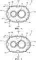
- flex limiting straps 58 are provided which join lock arms 54a, 54c to their adjacent skirt segments 54b, 54d and which limit the extent to which lock arms 54a, 54c are able to flex away from axis 32. More specifically, one flex limiting strap 58 joins lock arm 54a to skirt segment 54b, one flex limiting strap 58 joins lock arm 54a to skirt segment 54d, one flex limiting strap 58 joins lock arm 54c to skirt segment 54b, and one flex limiting strap 58 joints lock arm 54c to skirt segment 54d.
- Each flex limiting strap is configured to elastically deform as its respective lock arm 54a, 54c is moved from a free state, i.e. not flexed as shown in Fig. 4 and on the left-hand side of Fig. 5 , to a flexed state, as shown in the right hand side of Fig. 5 , in which its respective lock arm 54a, 54c is able to clear first retention protuberance 44, shown as a dashed line for illustrative purposes, to allow assembly and disassembly of first seal retainer 22 from housing 18.
- first retention protuberance 44 shown as a dashed line for illustrative purposes
- flex limiting straps 58 when lock arm 54c is in the free state, flex limiting straps 58 as viewed in a direction parallel to axis 32 have a first portion 58a that is concave facing toward axis 32 which is flanked by second portion 58b and third portion 58c which are each concave facing away from axis 32.
- the concavity of one or more of first portion 58a, second portion 58b, and third portion 58c may be reversed and one or more of first portion 58a, second portion 58b, and third portion 58c may be omitted such that at least one portion remains that is concave, either facing toward axis 32 or facing away from axis 32.
- flex limiting straps 58 take the form of a pleat, and more particularly an accordion pleat, which expands when the respective lock arm 54a, 54c is flexed away from axis 32 and which contracts when the respective lock arm 54a, 54c returns to the free state.
- flex limiting straps 58 have a wall thickness 58d in a direction normal to axis 32 that is less than a wall thickness 54e in a direction normal to axis 32 of each skirt segment 54a-54d.
- lock arm 54a has been selected for illustrative purposes and that lock arm 54c and flex limiting straps 58 associated therewith would have the same described characteristics as lock arm 54a and flex limiting straps 58 associated therewith.
- lock arm 54a is moved to a flexed state as best seen in the right-hand side of Fig. 5 , one or more of first portion 58a, second portion 58b, and third portion 58c elastically distort to permit lock arm 54a to flex away from axis 32, and importantly, limit the extent to which lock arm 54a is able to flex away from axis 32. While Fig.
- first retention protuberances 44 has been illustrated in dashed lines in order to demonstrate that flexing of lock arm 54a is able to provide clearance from first retention protuberance 44 in order to permit assembly and disassembly.
- lock arm 54a has been selected for illustrative purposes and that lock arm 54c and flex limiting straps 58 associated therewith would have the same described characteristics as lock arm 54a and flex limiting straps 58 associated therewith. In this way, flex limiting straps 58 allow lock arm 54a and lock arm 54c to lift over their respective first retention protuberances 44 when first seal retainer 22 is being installed on housing 18 and when first seal retainer 22 is being removed from housing 18.
- flex limiting straps 58 prevent over-flexing of lock arm 54a and lock arm 54c, thereby ensuring reliable retention of first seal retainer 22 to housing 18.
- over-flexing refers to the condition where the elastic limit of lock arm 54a or lock arm 54c is exceeded such that lock arm 54a or lock arm 54c does not return to its original free state after removal of force used to flex lock arm 54a or lock arm 54c away from axis 32.
- First seal retainer 22 may be an electrically insulative material, and may be, by way of non-limiting example only, a synthetic polymer, for example nylon or PBT, which is net-formed by injecting a liquid polymer into a mold (not show) and then allowed to cool and solidify before being removed from the mold to yield first seal retainer 22 in finished form. Consequently all of the features described herein of first seal retainer 22 may be quickly and economically net-formed as a single piece of material.
- a synthetic polymer for example nylon or PBT
- first seal retainer 22 has been illustrated as employing two lock arms, namely lock arm 54a and lock arm 54c which are arranged in an alternating pattern with skirt segment 54b and skirt segment 54d, it should be understood that a lesser number of lock arms or a greater number of lock arms may be used, depending on the retention needs of first seal retainer 22.
- skirt segment 54b and skirt segment 54d may be used as lock arms in the same way as lock arm 54a and 54c by merely providing housing 18 with additional first retention protuberances associated with skirt segment 54b and skirt segment 54d. Consequently, flex limiting straps 58 may extend between adjacent lock arms.
- skirt segments 54a, 54b, 54c, 54d have been illustrated, it should be understood that a lesser number or a greater number of skirt segments may be utilized where an appropriate number of the provided skirt segments are employed as lock arms to meet the retention needs of first seal retainer 22.
- second seal retainer 26 is substantially the same as first seal retainer 22. Consequently, for brevity, second seal retainer 26 will not be described further herein, and it should be understood that the description of the features and properties of first seal retainer 22 are equally applicable to second seal retainer 26 for use in engaging second retention protuberances 46 to accommodate retention of second seal retainer 26 to housing 18.
Landscapes
- Engineering & Computer Science (AREA)
- Architecture (AREA)
- Civil Engineering (AREA)
- Structural Engineering (AREA)
- Connector Housings Or Holding Contact Members (AREA)
- Insulated Conductors (AREA)
- Insulating Bodies (AREA)
- Installation Of Indoor Wiring (AREA)
Abstract
Description
- The present invention relates a wire harness assembly; more particularly to a wire harness assembly having a housing which receives a seal and a seal retainer which retains the seal within the housing; and even more particularly to such a wire harness assembly where the seal retainer includes a lock arm which engages a complementary protuberance of the housing to retain the seal retainer to the housing.
- Wire harness assemblies of a variety of configurations are employed in systems for transmitting electric current or electrical signals from one device or location to another device or location. It is known for a wire harness assembly to include a housing into which one or more wires extends such that the one or more wires may terminate within the housing in order to facilitate connection with a complementary portion of the wire harness, i.e. a mating connector, or the one or more wires may be spliced together within the housing such that the housing provides protection to the termination or splice. It is also known to provide a seal at an interface where the one or more wires enter the housing in order to prevent contaminants such as water, dust, and dirt that are present outside of the housing from entering the housing at the interface. The seal is typically received within a recess of the housing and one or more apertures are provided through the seal in order to allow the one or more wires to pass therethrough to enter the housing. Consequently, inner peripheries of the one or more apertures are sealed to the one or more wires and an outer periphery of the seal is sealed to the housing. A seal retainer is provided in order to ensure that the seal remains properly positioned within the housing, thereby ensuring that the seal is able to carry out its intended function. One such seal retainer is illustrated in United States Patent No.
9,543,747 to Dew, et al. - What is needed is a wire harness assembly which minimizes or eliminates one or more of the shortcomings as set forth above.
- Briefly described, a wire harness assembly includes a housing defining an interior volume which extends into the housing along an axis, the interior volume having an interior surface having an interior perimeter, the housing also defining an outer surface having a retention protuberance extending outward therefrom; a seal received within the interior volume which engages the interior perimeter of the interior surface, the seal having a wire aperture extending therethrough; a wire extending through the wire aperture of the seal such that the wire aperture circumferentially engages the wire; and a seal retainer having a seal retainer wall which traverses the axis and which retains the seal within the interior volume, the seal retainer also having a seal retainer skirt which is defined by a plurality of skirt segments which extend from the seal retainer wall such that each of the plurality of skirt segments is positioned laterally to the outer surface; wherein one of the plurality of skirt segments defines a lock arm having a lock aperture which captures the retention protuberance therein, thereby retaining the seal retainer to the housing and limiting motion of the seal retainer relative to the housing along the axis, the lock arm being resilient and compliant which allows the lock arm to flex away from the axis, thereby allowing the lock arm to lift over the retention protuberance when the seal retainer is being installed on the housing and when the seal retainer is being removed from the housing, the seal retainer having a flex limiting strap joining the lock arm to an adjacent one of the plurality of skirt segments which limits the extent to which the lock arm flexes away from the axis. Since the flex limiting strap limits the extent to which the lock arm flexes away from the axis, over-flexing of the lock arm can be prevented which could otherwise exceed the elastic limit of the lock arm and prevent the lock arm from returning back to its original position which could prevent the lock arm from retaining the seal retainer to the housing.
- This invention will be further described with reference to the accompanying drawings in which:
-
Fig. 1 an exploded isometric view of a wire harness assembly of the present invention; -
Fig. 2 is an enlarged portion ofFig. 1 shown with a seal of the wire harness assembly installed in a housing of the wire harness assembly; -
Fig. 3 is the view ofFig. 2 now shown with a seal retainer of the wire harness assembly installed on the housing; -
Fig. 4 is an elevation view of the seal retainer shown in a free state; and -
Fig. 5 is the elevation view ofFig. 4 now shown with one lock arm in free state and one lock arm in a flexed state. - In accordance with a non-limiting embodiment of the present invention and referring initially to
Fig. 1 , awire harness assembly 10 is illustrated in an exploded isometric view. As embodied herein, by way of non-limiting example only,wire harness assembly 10 generally includes afirst wire 12, asecond wire 14, athird wire 16, ahousing 18, afirst seal 20, afirst seal retainer 22, asecond seal 24, and asecond seal retainer 26. In particular,first seal retainer 22 andsecond seal retainer 26 are provided with features, as will be described in greater detail below, which prevent or minimize the likelihood of damagingfirst seal retainer 22 andsecond seal retainer 26 at least during disassembly fromhousing 18. In the paragraphs that follow, the individual elements ofwire harness assembly 10 will be described in greater detail. - With regard to
first wire 12,second wire 14, andthird wire 16, referred to collectively aswires wires wires Wires Wires wires wires Wires wires Wires splice 28 which is protected from environmental effects by being located withinhousing 18. -
Housing 18 extends from afirst end 18a to asecond end 18b such thathousing 18 is tubular, thereby defining aninterior volume 30 which extends intohousing 18 along anaxis 32.Interior volume 30 is defined by aninterior surface 34 ofhousing 18 such thatinterior surface 34 has an interiorperimeter surrounding axis 32.Housing 18 also defines anouter surface 38 which opposesinterior surface 34.Housing 18 is preferably an electrically insulative material, and may be, by way of non-limiting example only, a synthetic polymer, for example nylon or PBT, which may be net-formed by injecting a liquid polymer into a mold (not show) and then allowed to cool and solidify before being removed from the mold to yieldhousing 18 in finished form. - A
first housing flange 40 is provided onouter surface 38 such thatfirst housing flange 40 extends radially outward fromhousing 18 at a location that is axially spaced fromfirst end 18a while asecond housing flange 42 is provided onouter surface 38 such thatsecond housing flange 42 extends radially outward fromhousing 18 at a location that is axially spaced fromsecond end 18b. As shown,first housing flange 40 andsecond housing flange 42 are each substantially perpendicular toaxis 32 and extend around the entire perimeter ofouter surface 38, however, it should be understood thatfirst housing flange 40 andsecond housing flange 42 may alternatively extend less than the entire perimeter ofouter surface 38 and may be segmented. In this way,first housing flange 40 limits the extent to whichfirst seal retainer 22 is slid ontohousing 18 fromfirst end 18a andsecond housing flange 42 limits the extent to whichsecond seal retainer 26 is slid ontohousing 18 fromsecond end 18b. - With continued referenced to
Fig. 1 , and now with additional reference toFig. 2 ,first retention protuberances 44, which are used to retainfirst seal retainer 22 tohousing 18, are provided betweenfirst end 18a ofhousing 18 andfirst housing flange 40 such that eachfirst retention protuberance 44 extends outward fromouter surface 38. As shown,first retention protuberances 44 may be evenly spaced around the perimeter ofouter surface 38, but may alternatively be unevenly spaced around the perimeter ofouter surface 38. Also as shown, twofirst retention protuberances 44 are provided, however, a lesser or greater number may be provided depending on the retention needs offirst seal retainer 22.First retention protuberances 44 include a ramp portion 44a which is inclined relative toaxis 32 such that ramp portion 44a diverges fromaxis 32 when moving in a direction away fromfirst end 18a towardfirst housing flange 40.First retention protuberances 44 also include a shoulder portion 44b which faces towardfirst housing flange 40 and which is preferably substantially perpendicular toaxis 32. In this way, a channel is defined axially betweenfirst housing flange 40 and shoulder portion 44b. - Second retention protuberances 46 (only one
second retention protuberance 46 is visible in the figures), which are used to retainsecond seal retainer 26 tohousing 18, are provided betweensecond end 18b ofhousing 18 andsecond housing flange 42 such that eachsecond retention protuberance 46 extends outward fromouter surface 38.second retention protuberances 46 may be substantially the same asfirst retention protuberances 44, consequently, for brevity,second retention protuberances 46 will not be described further herein. -
First seal 20 is received withininterior volume 30 and is complementary tointerior surface 34 proximal tofirst end 18a such thatfirst seal 20 engages the interior perimeter ofinterior surface 34 proximal tofirst end 18a.First seal 20 includesfirst wire apertures axis 32 such thatfirst wire 12 extends throughfirst wire aperture 20a andsecond wire 14 extends throughfirst wire aperture 20b.First wire aperture 20a circumferentially engagesfirst wire 12 andfirst wire aperture 20b circumferentially engagessecond wire 14.First seal 20 is made of a resilient and compliant material which may be, by way of non-limiting example only, a silicone-based rubber. In this way, contaminants such as, by way of non-limiting example only, water, dust, and dirt that are present outside ofhousing 18 are prevented from enteringhousing 18 atfirst end 18a, thereby providing protection tosplice 28. -
Second seal 24 is received withininterior volume 30 and is complementary tointerior surface 34 proximal tosecond end 18b such thatsecond seal 24 engages the interior perimeter ofinterior surface 34 proximal tosecond end 18b.Second seal 24 includessecond wire aperture 24a extending therethrough in the direction ofaxis 32 such thatthird wire 16 extends throughsecond wire aperture 24a.Second wire aperture 24a circumferentially engagesthird wire 16.Second seal 24 is made of a resilient and compliant material which may be, by way of non-limiting example only, a silicone-based rubber. In this way, contaminants such as, by way of non-limiting example only, water, dust, and dirt that are present outside ofhousing 18 are prevented from enteringhousing 18 atsecond end 18b, thereby providing protection tosplice 28. - With continued reference to
Figs. 1 and2 , and now with additional reference toFigs. 3-5 ,first seal retainer 22 includes aseal retainer wall 48 which traversesaxis 32 atfirst end 18a, thereby retainingfirst seal 20 withininterior volume 30. As shown, sealretainer wall 48 may be substantially perpendicular toaxis 32 and includes sealretainer wire towers 50a, 50b extending therefrom in a direction away fromhousing 18 and substantially parallel toaxis 32. Sealretainer wire towers 50a, 50b include sealretainer wire apertures first wire 12 extends through sealretainer wire aperture 52a andsecond wire 14 extends through sealretainer wire aperture 52b. -
First seal retainer 22 also includes askirt 54 which is defined by a plurality ofskirt segments seal retainer wall 48 such that eachskirt segment outer surface 38 ofhousing 18 which lies betweenfirst end 18a andfirst housing flange 40. As illustrated herein, twoskirt segments first retention protuberances 44, and consequently,skirt segments first seal retainer 22 tohousing 18. Hereinafter,skirt segments arms Lock arms lock aperture 56 extending therethrough in a direction which is substantially perpendicular toaxis 32.Lock arms arms axis 32 in order to allow for installation and removal offirst seal retainer 22 onhousing 18. In this way, whenfirst seal retainer 22 is installed onhousing 18 by slidingfirst seal retainer 22 overfirst end 18a in the direction ofaxis 32,first retention protuberances 44 elastically flexrespective lock arms axis 32 by riding up on ramp portion 44a offirst retention protuberances 44 untilfirst seal retainer 22 is installed onhousing 18 sufficient far so as to alignfirst retention protuberances 44 withrespective lock aperture 56 ofrespective lock arms lock arms arms first retention protuberances 44 are captured withinrespective lock aperture 56 ofrespective lock arms first seal retainer 22 tohousing 18 since shoulder portion 44b offirst retention protuberances 44 engageslock apertures 56 to limit motion offirst seal retainer 22 relative tohousing 18 in the direction ofaxis 32 and since a portion of eachlock arm first housing flange 40 and shoulder portion 44b. - In order to prevent over-flexing of
lock arms first seal retainer 22 fromhousing 18,flex limiting straps 58 are provided which joinlock arms adjacent skirt segments arms axis 32. More specifically, oneflex limiting strap 58 joinslock arm 54a toskirt segment 54b, oneflex limiting strap 58 joinslock arm 54a toskirt segment 54d, oneflex limiting strap 58 joinslock arm 54c toskirt segment 54b, and oneflex limiting strap 58 joints lockarm 54c toskirt segment 54d. Each flex limiting strap is configured to elastically deform as itsrespective lock arm Fig. 4 and on the left-hand side ofFig. 5 , to a flexed state, as shown in the right hand side ofFig. 5 , in which itsrespective lock arm first retention protuberance 44, shown as a dashed line for illustrative purposes, to allow assembly and disassembly offirst seal retainer 22 fromhousing 18. As may be best seen inFig. 4 and in the left-hand side ofFig. 5 , whenlock arm 54c is in the free state,flex limiting straps 58 as viewed in a direction parallel toaxis 32 have afirst portion 58a that is concave facing towardaxis 32 which is flanked bysecond portion 58b andthird portion 58c which are each concave facing away fromaxis 32. Alternatively, the concavity of one or more offirst portion 58a,second portion 58b, andthird portion 58c may be reversed and one or more offirst portion 58a,second portion 58b, andthird portion 58c may be omitted such that at least one portion remains that is concave, either facing towardaxis 32 or facing away fromaxis 32. In this way,flex limiting straps 58 take the form of a pleat, and more particularly an accordion pleat, which expands when therespective lock arm axis 32 and which contracts when therespective lock arm flex limiting straps 58 are able to expand as necessary,flex limiting straps 58 have awall thickness 58d in a direction normal toaxis 32 that is less than awall thickness 54e in a direction normal toaxis 32 of eachskirt segment 54a-54d. It should be understood thatlock arm 54a has been selected for illustrative purposes and thatlock arm 54c andflex limiting straps 58 associated therewith would have the same described characteristics aslock arm 54a andflex limiting straps 58 associated therewith. Whenlock arm 54a is moved to a flexed state as best seen in the right-hand side ofFig. 5 , one or more offirst portion 58a,second portion 58b, andthird portion 58c elastically distort to permitlock arm 54a to flex away fromaxis 32, and importantly, limit the extent to whichlock arm 54a is able to flex away fromaxis 32. WhileFig. 5 does not showhousing 18 in general, onefirst retention protuberances 44 has been illustrated in dashed lines in order to demonstrate that flexing oflock arm 54a is able to provide clearance fromfirst retention protuberance 44 in order to permit assembly and disassembly. It should be understood thatlock arm 54a has been selected for illustrative purposes and thatlock arm 54c andflex limiting straps 58 associated therewith would have the same described characteristics aslock arm 54a andflex limiting straps 58 associated therewith. In this way,flex limiting straps 58 allowlock arm 54a and lockarm 54c to lift over their respectivefirst retention protuberances 44 whenfirst seal retainer 22 is being installed onhousing 18 and whenfirst seal retainer 22 is being removed fromhousing 18. However,flex limiting straps 58 prevent over-flexing oflock arm 54a and lockarm 54c, thereby ensuring reliable retention offirst seal retainer 22 tohousing 18. As used herein, over-flexing refers to the condition where the elastic limit oflock arm 54a or lockarm 54c is exceeded such thatlock arm 54a or lockarm 54c does not return to its original free state after removal of force used to flexlock arm 54a or lockarm 54c away fromaxis 32. -
First seal retainer 22 may be an electrically insulative material, and may be, by way of non-limiting example only, a synthetic polymer, for example nylon or PBT, which is net-formed by injecting a liquid polymer into a mold (not show) and then allowed to cool and solidify before being removed from the mold to yieldfirst seal retainer 22 in finished form. Consequently all of the features described herein offirst seal retainer 22 may be quickly and economically net-formed as a single piece of material. - While
first seal retainer 22 has been illustrated as employing two lock arms, namely lockarm 54a and lockarm 54c which are arranged in an alternating pattern withskirt segment 54b andskirt segment 54d, it should be understood that a lesser number of lock arms or a greater number of lock arms may be used, depending on the retention needs offirst seal retainer 22. By way of non-limiting example,skirt segment 54b andskirt segment 54d may be used as lock arms in the same way aslock arm housing 18 with additional first retention protuberances associated withskirt segment 54b andskirt segment 54d. Consequently,flex limiting straps 58 may extend between adjacent lock arms. Furthermore, while fourskirt segments first seal retainer 22. - With the exception of accommodating only
third wire 16, as opposed tofirst wire 12 andsecond wire 14,second seal retainer 26 is substantially the same asfirst seal retainer 22. Consequently, for brevity,second seal retainer 26 will not be described further herein, and it should be understood that the description of the features and properties offirst seal retainer 22 are equally applicable tosecond seal retainer 26 for use in engagingsecond retention protuberances 46 to accommodate retention ofsecond seal retainer 26 tohousing 18.
Claims (9)
- A wire harness assembly (10) comprising:a housing (18) defining an interior volume (30) which extends into said housing (18) along an axis (32), said interior volume (30) having an interior surface (34) having an interior perimeter, said housing (18) also defining an outer surface (38) having a retention protuberance (44) extending outward therefrom;a seal (20) received within said interior volume (30) which engages said interior perimeter of said interior surface (34), said seal (20) having a wire (12) aperture extending therethrough;a wire (12) extending through said wire aperture (20a, 20b) of said seal (20) such that said wire aperture (20a, 20b) circumferentially engages said wire (12); anda seal retainer (22) having a seal retainer wall (48) which traverses said axis (32) and which retains said seal (20) within said interior volume (30), said seal retainer (22) also having a seal retainer skirt (54) which is defined by a plurality of skirt segments (54a) which extend from said seal retainer wall (48) such that each of said plurality of skirt segments (54a) is positioned laterally to said outer surface (38); wherein one of said plurality of skirt segments (54a) defines a lock arm (54a) having a lock aperture (56) which captures said retention protuberance (44) therein, thereby retaining said seal retainer (22) to said housing (18) and limiting motion of said seal retainer (22) relative to said housing (18) along said axis (32), said lock arm (54a) being resilient and compliant which allows said lock arm (54a) to flex away from said axis (32), thereby allowing said lock arm (54a) to lift over said retention protuberance (44) when said seal retainer (22) is being installed on said housing (18) and when said seal retainer (22) is being removed from said housing (18), said seal retainer (22) having a flex limiting strap (58) joining said lock arm (54a) to an adjacent one of said plurality of skirt segments (54a) which limits the extent to which said lock arm (54a) flexes away from said axis (32).
- A wire harness assembly (10) as in claim 1, wherein said flex limiting strap (58) is a first flex limiting strap (58) joining said lock arm (54a) to a first adjacent one of said plurality of skirt segments (54a), said seal retainer (22) also having a second flex limiting strap (58) joining said lock arm (54a) to a second adjacent one of said plurality of skirt segments (54a) such that said first flex limiting strap (58) and said second flex limiting strap (58) limit the extent to which said lock arm (54a) flexes away from said axis (32).
- A wire harness assembly (10) as in any preceding claim, wherein:said lock arm (54a) is flexible between a free state in which said retention protuberance (44) is captured within said lock aperture (56) and a flexed state in which said retention protuberance (44) is not within said lock aperture (56); andsaid flex limiting strap (58) as viewed in a direction parallel to said axis (32) when said lock arm (54a) is in said free state has a first portion (58a) that is concave facing toward said axis (32).
- A wire harness assembly (10) as in any preceding claim, wherein said flex limiting strap (58) as viewed in a direction parallel to said axis (32) when said lock arm (54a) is in said free state also has a second portion (58b) that is concave facing away from said axis (32) and a third portion (58c) that is concave facing away from said axis (32) such that said first portion (58a) is located between said second portion (58b) and said third portion (58c).
- A wire harness assembly (10) as in claim 4, wherein when said lock arm (54a) is in said flexed state, at least one of said first portion (58a), said second portion (58b), and said third portion (58c) is distorted compared to when said lock arm (54a) is in said free state.
- A wire harness assembly (10) as in claim 3 wherein when said lock arm (54a) is in said flexed state, said first portion (58a) is distorted compared to when said lock arm (54a) is in said free state.
- A wire harness assembly (10) as in any preceding claim, wherein said flex limiting strap (58) is a pleat which expands when said lock arm (54a) flexes away from said axis (32) and which contracts when said lock arm (54a) returns toward said axis (32).
- A wire harness assembly (10) as in any preceding claim, wherein:said flex limiting strap (58) has a first wall thickness (54e) in a direction normal to said axis (32); andsaid lock arm (54a) has a second wall thickness (54e) in a direction normal to said axis (32) such that said first wall thickness (54e) is less than said second wall thickness (54e).
- A wire harness assembly (10) as in any preceding claim, wherein said flex limiting strap (58) limits the extent to which said lock arm (54a) flexes away from said axis (32) so as to not exceed an elastic limit of said lock arm (54a).
Applications Claiming Priority (1)
| Application Number | Priority Date | Filing Date | Title |
|---|---|---|---|
| US15/626,701 US9954347B1 (en) | 2017-06-19 | 2017-06-19 | Wire harness assembly and seal retainer therefore |
Publications (2)
| Publication Number | Publication Date |
|---|---|
| EP3419130A1 true EP3419130A1 (en) | 2018-12-26 |
| EP3419130B1 EP3419130B1 (en) | 2020-09-09 |
Family
ID=61951809
Family Applications (1)
| Application Number | Title | Priority Date | Filing Date |
|---|---|---|---|
| EP18177121.3A Active EP3419130B1 (en) | 2017-06-19 | 2018-06-11 | Wire harness assembly and seal retainer therefore |
Country Status (5)
| Country | Link |
|---|---|
| US (1) | US9954347B1 (en) |
| EP (1) | EP3419130B1 (en) |
| JP (1) | JP6580214B2 (en) |
| KR (1) | KR102071796B1 (en) |
| CN (1) | CN109149457B (en) |
Families Citing this family (3)
| Publication number | Priority date | Publication date | Assignee | Title |
|---|---|---|---|---|
| KR102075138B1 (en) * | 2018-09-28 | 2020-02-10 | 현대자동차(주) | Connector |
| JP7271498B2 (en) * | 2020-12-16 | 2023-05-11 | 矢崎総業株式会社 | equipment connector |
| US20240280123A1 (en) * | 2023-02-16 | 2024-08-22 | Illinois Tool Works Inc. | Compressing Snap Grommet |
Citations (5)
| Publication number | Priority date | Publication date | Assignee | Title |
|---|---|---|---|---|
| GB2112219A (en) * | 1981-11-30 | 1983-07-13 | Tokai Electric Wire | Waterproof connector |
| WO2014070851A1 (en) * | 2012-10-31 | 2014-05-08 | Delphi Technologies, Inc. | Device and method for splicing shielded wire cables |
| US20150114711A1 (en) * | 2013-10-30 | 2015-04-30 | Delphi Technologies, Inc. | Method for splicing shielded wire cables and cables made by same |
| WO2015185511A2 (en) * | 2014-06-04 | 2015-12-10 | Kostal Kontakt Systeme Gmbh | Electric device |
| US9653859B1 (en) * | 2016-04-11 | 2017-05-16 | Delphi Technologies, Inc. | Electrical connector system |
Family Cites Families (59)
| Publication number | Priority date | Publication date | Assignee | Title |
|---|---|---|---|---|
| US5283807A (en) * | 1992-10-21 | 1994-02-01 | Tutankhamon Electronics, Inc. | EMI suppression coding |
| JP3048485B2 (en) * | 1993-03-15 | 2000-06-05 | 矢崎総業株式会社 | Beam welding method of terminal and electric wire |
| JP2904390B2 (en) * | 1993-12-20 | 1999-06-14 | 矢崎総業株式会社 | Connector with mating operation lever |
| JP2921647B2 (en) * | 1994-11-22 | 1999-07-19 | 矢崎総業株式会社 | Locking mechanism for low insertion / extraction connector |
| US5792987A (en) * | 1995-08-28 | 1998-08-11 | Raychem Corporation | Sealing device |
| JP3324724B2 (en) * | 1996-02-16 | 2002-09-17 | 矢崎総業株式会社 | Lever mating connector |
| US5806139A (en) * | 1996-04-24 | 1998-09-15 | Hi-Lex Corporation | Grommet assembly |
| PE69897A1 (en) * | 1996-05-02 | 1997-11-05 | Raychem Sa Nv | CLOSE TO SEAL AN OPENING |
| JP3275290B2 (en) * | 1996-08-09 | 2002-04-15 | 住友電装株式会社 | Lever connector |
| JP3450970B2 (en) * | 1996-10-17 | 2003-09-29 | アスモ株式会社 | Water harness connection waterproofing |
| US5965847A (en) * | 1996-11-12 | 1999-10-12 | Sumitomo Wiring Systems, Ltd. | Shield connector |
| US5928011A (en) * | 1997-10-28 | 1999-07-27 | General Motors Corporation | Slide lock position assurance and release lever |
| JP3884153B2 (en) * | 1998-01-14 | 2007-02-21 | 古河電気工業株式会社 | Grommet |
| US6335488B1 (en) * | 1998-10-02 | 2002-01-01 | Arlington Industries, Inc. | Snap in cable connector |
| US6114630A (en) * | 1998-10-29 | 2000-09-05 | Arlington Industries, Inc. | Snap in cable connector |
| FR2791189B1 (en) * | 1999-03-19 | 2001-05-11 | France Telecom | DEVICE FOR CONNECTING A MULTITUBULAR INFRASTRUCTURE AND METHOD FOR ACCESSING THE DEVICE |
| US6362427B1 (en) * | 1999-08-11 | 2002-03-26 | Avaya Technology Corp. | Low profile adapter for variable size tubing |
| US6521831B1 (en) * | 1999-08-13 | 2003-02-18 | Arlington Industries, Inc. | Duplex electrical connector with spring steel cable retainer |
| US6133529A (en) * | 1999-12-29 | 2000-10-17 | Arunction Industries, Inc. | Liner assembly |
| US6843670B2 (en) * | 2000-06-29 | 2005-01-18 | Molex Incorporated | IC card connector |
| US6485332B1 (en) * | 2000-07-18 | 2002-11-26 | Yazaki North America | System for reconfiguring connector cover and seal |
| US6441305B1 (en) * | 2000-09-28 | 2002-08-27 | Tyco Electronics Corporation | High temperature slip-sealing grommet systems |
| US6538201B1 (en) * | 2001-12-26 | 2003-03-25 | Arlington Industries, Inc | Threaded snap in connector |
| US6642451B1 (en) * | 2001-10-22 | 2003-11-04 | Arlington Industries, Inc. | Electrical connector |
| JP4036135B2 (en) * | 2003-04-18 | 2008-01-23 | 住友電装株式会社 | Grommet |
| US7083471B2 (en) * | 2003-06-18 | 2006-08-01 | Autonetworks Technologies, Ltd. | Connecting structure of connector, shield connector and lever type connector |
| US6916988B1 (en) * | 2004-07-12 | 2005-07-12 | Bridgeport Fittings, Inc. | Electrical connector with frustro conical snap fit retaining ring |
| US7488905B2 (en) * | 2004-09-13 | 2009-02-10 | Bridgeport Fittings, Inc. | Electrical connector with outer retainer ring and internal unidirectional conductor retainer |
| US7205489B2 (en) * | 2004-09-13 | 2007-04-17 | Bridgeport Fittings, Inc. | Snap fit electrical connector assembly with operating tool for facilitating the connection of a connector assembly to an electrical box |
| US7151223B2 (en) * | 2004-09-13 | 2006-12-19 | Bridgeport Fittings, Inc. | Snap fit electrical connector assembly with outer frustro conical retainer ring and internal unidirectional snap fit wire conductor retainer |
| US7952034B2 (en) * | 2004-09-13 | 2011-05-31 | Bridgeport Fittings, Inc. | Strap type electrical connector with frustro-conical retaining ring and improved clamping strap for either nonmetallic cables or armor or metal clad cables |
| US7075007B2 (en) * | 2004-09-13 | 2006-07-11 | Bridgeport Fittings, Inc. | Snap fit electrical connector assembly with conical outer snap fit retainer and one or more internal snap fit wire retainers |
| US7057107B2 (en) * | 2004-09-13 | 2006-06-06 | Bridgeport Fittings, Inc. | Snap fit electrical connector assembly with conical outer snap fit retainer and externally mounted internal wire retainer |
| US8350163B2 (en) * | 2004-09-13 | 2013-01-08 | Bridgeport, Fittings, Inc. | Electrical connector having snap in frustro-conical retaining ring with improved conductivity |
| US7064272B2 (en) * | 2004-09-13 | 2006-06-20 | Bridgeport Fittings, Inc. | Snap in electrical connector assembly with unidirectional wire conductor retainer ring |
| US7154042B2 (en) * | 2004-09-13 | 2006-12-26 | Bridgeport Fittings, Inc. | Electrical connector with snap fit retainer ring constructed to enhance the connection of the connector to an electrical box |
| US7723623B2 (en) * | 2004-09-13 | 2010-05-25 | Bridgeport Fittings, Inc. | Electrical duplex connector having an integrally formed connector body with a frustro-conical retaining ring and unidirectional cable retainers |
| US7214890B2 (en) * | 2004-09-13 | 2007-05-08 | Bridgeport Fittings, Inc. | Electrical connector having an outlet end angularly disposed relative an inlet end with outer retainer ring about the outlet end and internal unidirectional conductor retainer in the inlet end |
| JP4415267B2 (en) * | 2005-02-02 | 2010-02-17 | 住友電装株式会社 | Shield connector |
| JP5102443B2 (en) * | 2005-10-18 | 2012-12-19 | 矢崎総業株式会社 | Wire harness side shield connector |
| US7705240B2 (en) * | 2005-10-27 | 2010-04-27 | Pentair Water Pool And Spa, Inc. | Cord seal for swimming pool and spa light niches |
| US7060900B1 (en) * | 2006-01-24 | 2006-06-13 | Arlington Industries, Inc. | Snap engagement electrical fitting with flangeless connector body |
| US7344406B2 (en) * | 2006-05-12 | 2008-03-18 | Astoria Industries Of Iowa | Wiring harness connector for a truck topper |
| US7432452B2 (en) * | 2006-06-05 | 2008-10-07 | Halex/Scott Fetzer Company | Snap-in connector for electrical junction box |
| US7390980B1 (en) * | 2007-04-27 | 2008-06-24 | Arlington Industries, Inc. | Snap engagement electrical connector with split connector body |
| US7868251B2 (en) * | 2008-04-08 | 2011-01-11 | Delphi Technologies, Inc. | Shielded electric cable assembly |
| US8162693B2 (en) * | 2009-05-04 | 2012-04-24 | Bridgeport Fittings, Inc. | Snap-in electrical connector with locking cam and method of use |
| US8022304B2 (en) * | 2009-06-05 | 2011-09-20 | Ford Global Technologies, Llc | Grommet |
| US8253043B1 (en) * | 2009-07-10 | 2012-08-28 | Bridgeport Fittings, Inc. | Snap-in electrical connector with multiple function retainer ring |
| CN201629425U (en) * | 2010-03-18 | 2010-11-10 | 美国莫列斯股份有限公司 | Electrical connection device |
| US8487197B2 (en) * | 2010-08-11 | 2013-07-16 | Bridgeport Fittings, Inc. | Removable push electrical fitting for electrical metallic tubing or EMT having improved pullout resistance |
| US8274000B2 (en) * | 2010-08-11 | 2012-09-25 | Bridgeport Fittings, Inc. | Removable push electrical fitting for electrical metallic tubing or EMT |
| JP5651436B2 (en) * | 2010-11-15 | 2015-01-14 | 矢崎総業株式会社 | connector |
| KR101269686B1 (en) * | 2010-11-22 | 2013-05-30 | (주)동아금속 | Hose clamp |
| JP5790492B2 (en) * | 2011-12-28 | 2015-10-07 | 住友電装株式会社 | Wire fixing member |
| GB2502870B (en) * | 2012-04-16 | 2015-07-29 | Gripple Ltd | Insulated electric cord |
| KR101503507B1 (en) * | 2014-04-09 | 2015-03-18 | 주식회사 경신 | Connector for vehicle |
| JP6229951B2 (en) * | 2014-12-19 | 2017-11-15 | 住友電装株式会社 | Grommet and seal structure using grommet |
| JP2016219235A (en) * | 2015-05-20 | 2016-12-22 | 住友電装株式会社 | connector |
-
2017
- 2017-06-19 US US15/626,701 patent/US9954347B1/en active Active
-
2018
- 2018-06-11 EP EP18177121.3A patent/EP3419130B1/en active Active
- 2018-06-14 KR KR1020180067956A patent/KR102071796B1/en active Active
- 2018-06-15 CN CN201810618713.2A patent/CN109149457B/en active Active
- 2018-06-15 JP JP2018114406A patent/JP6580214B2/en active Active
Patent Citations (6)
| Publication number | Priority date | Publication date | Assignee | Title |
|---|---|---|---|---|
| GB2112219A (en) * | 1981-11-30 | 1983-07-13 | Tokai Electric Wire | Waterproof connector |
| WO2014070851A1 (en) * | 2012-10-31 | 2014-05-08 | Delphi Technologies, Inc. | Device and method for splicing shielded wire cables |
| US20150114711A1 (en) * | 2013-10-30 | 2015-04-30 | Delphi Technologies, Inc. | Method for splicing shielded wire cables and cables made by same |
| US9543747B2 (en) | 2013-10-30 | 2017-01-10 | Delphi Technologies, Inc. | Method for splicing shielded wire cables |
| WO2015185511A2 (en) * | 2014-06-04 | 2015-12-10 | Kostal Kontakt Systeme Gmbh | Electric device |
| US9653859B1 (en) * | 2016-04-11 | 2017-05-16 | Delphi Technologies, Inc. | Electrical connector system |
Also Published As
| Publication number | Publication date |
|---|---|
| KR102071796B1 (en) | 2020-01-30 |
| JP2019009114A (en) | 2019-01-17 |
| CN109149457A (en) | 2019-01-04 |
| US9954347B1 (en) | 2018-04-24 |
| CN109149457B (en) | 2020-11-27 |
| KR20180138149A (en) | 2018-12-28 |
| JP6580214B2 (en) | 2019-09-25 |
| EP3419130B1 (en) | 2020-09-09 |
Similar Documents
| Publication | Publication Date | Title |
|---|---|---|
| US7229303B2 (en) | Environmentally sealed connector with blind mating capability | |
| KR101031898B1 (en) | Connectors, Jack Parts, Electronics and Plug Parts | |
| EP3168939B1 (en) | Anti-rotation seal for connector assembly | |
| CN105896153B (en) | Electric connector and method for manufacturing network connection | |
| US20140213089A1 (en) | Plug connector | |
| US10148032B1 (en) | Sealed electrical connector assembly and wire seal | |
| EP3084905B1 (en) | Connector part of a connector unit | |
| EP3419130B1 (en) | Wire harness assembly and seal retainer therefore | |
| US10594086B2 (en) | Electrical shielding member for a network connector | |
| CN111668654A (en) | Connector assembly and assembling method thereof | |
| WO2010087945A1 (en) | Connector receptacle with gasket | |
| US20180294629A1 (en) | Device and method for splicing shielded wire cables | |
| US20190372328A1 (en) | Cable bushing having shielding and sealing properties | |
| CN110168810B (en) | Shielded cable with boundary contact through assembly | |
| US8241054B2 (en) | Attachment ring for attaching a shield of an electrical cable to a backshell | |
| CN104682090B (en) | Electrical connector with wire retention tube | |
| EP3836307A1 (en) | Cable lug for a connector | |
| JP6835024B2 (en) | Wire harness | |
| US9647384B2 (en) | Back body for coaxial connector | |
| EP4475352A1 (en) | Sealed connector assembly with combination connector seal | |
| EP3111514B1 (en) | Improved device for the ground connection of coaxial cables | |
| CN112513477A (en) | System and method for sealing metal fasteners from electrolyte in areas of dissimilar metals | |
| US10784628B2 (en) | Electrical plug connector | |
| EP3570387B1 (en) | Cable connection system with cable fixation shell | |
| KR20250114370A (en) | Protective device for sealing the plug connection |
Legal Events
| Date | Code | Title | Description |
|---|---|---|---|
| PUAI | Public reference made under article 153(3) epc to a published international application that has entered the european phase |
Free format text: ORIGINAL CODE: 0009012 |
|
| STAA | Information on the status of an ep patent application or granted ep patent |
Free format text: STATUS: THE APPLICATION HAS BEEN PUBLISHED |
|
| AK | Designated contracting states |
Kind code of ref document: A1 Designated state(s): AL AT BE BG CH CY CZ DE DK EE ES FI FR GB GR HR HU IE IS IT LI LT LU LV MC MK MT NL NO PL PT RO RS SE SI SK SM TR |
|
| AX | Request for extension of the european patent |
Extension state: BA ME |
|
| STAA | Information on the status of an ep patent application or granted ep patent |
Free format text: STATUS: REQUEST FOR EXAMINATION WAS MADE |
|
| 17P | Request for examination filed |
Effective date: 20190624 |
|
| RBV | Designated contracting states (corrected) |
Designated state(s): AL AT BE BG CH CY CZ DE DK EE ES FI FR GB GR HR HU IE IS IT LI LT LU LV MC MK MT NL NO PL PT RO RS SE SI SK SM TR |
|
| STAA | Information on the status of an ep patent application or granted ep patent |
Free format text: STATUS: EXAMINATION IS IN PROGRESS |
|
| 17Q | First examination report despatched |
Effective date: 20190905 |
|
| GRAP | Despatch of communication of intention to grant a patent |
Free format text: ORIGINAL CODE: EPIDOSNIGR1 |
|
| STAA | Information on the status of an ep patent application or granted ep patent |
Free format text: STATUS: GRANT OF PATENT IS INTENDED |
|
| INTG | Intention to grant announced |
Effective date: 20200428 |
|
| GRAS | Grant fee paid |
Free format text: ORIGINAL CODE: EPIDOSNIGR3 |
|
| GRAA | (expected) grant |
Free format text: ORIGINAL CODE: 0009210 |
|
| STAA | Information on the status of an ep patent application or granted ep patent |
Free format text: STATUS: THE PATENT HAS BEEN GRANTED |
|
| AK | Designated contracting states |
Kind code of ref document: B1 Designated state(s): AL AT BE BG CH CY CZ DE DK EE ES FI FR GB GR HR HU IE IS IT LI LT LU LV MC MK MT NL NO PL PT RO RS SE SI SK SM TR |
|
| REG | Reference to a national code |
Ref country code: GB Ref legal event code: FG4D |
|
| REG | Reference to a national code |
Ref country code: AT Ref legal event code: REF Ref document number: 1312750 Country of ref document: AT Kind code of ref document: T Effective date: 20200915 Ref country code: CH Ref legal event code: EP |
|
| REG | Reference to a national code |
Ref country code: IE Ref legal event code: FG4D |
|
| REG | Reference to a national code |
Ref country code: DE Ref legal event code: R096 Ref document number: 602018007527 Country of ref document: DE |
|
| REG | Reference to a national code |
Ref country code: LT Ref legal event code: MG4D |
|
| PG25 | Lapsed in a contracting state [announced via postgrant information from national office to epo] |
Ref country code: SE Free format text: LAPSE BECAUSE OF FAILURE TO SUBMIT A TRANSLATION OF THE DESCRIPTION OR TO PAY THE FEE WITHIN THE PRESCRIBED TIME-LIMIT Effective date: 20200909 Ref country code: NO Free format text: LAPSE BECAUSE OF FAILURE TO SUBMIT A TRANSLATION OF THE DESCRIPTION OR TO PAY THE FEE WITHIN THE PRESCRIBED TIME-LIMIT Effective date: 20201209 Ref country code: FI Free format text: LAPSE BECAUSE OF FAILURE TO SUBMIT A TRANSLATION OF THE DESCRIPTION OR TO PAY THE FEE WITHIN THE PRESCRIBED TIME-LIMIT Effective date: 20200909 Ref country code: HR Free format text: LAPSE BECAUSE OF FAILURE TO SUBMIT A TRANSLATION OF THE DESCRIPTION OR TO PAY THE FEE WITHIN THE PRESCRIBED TIME-LIMIT Effective date: 20200909 Ref country code: BG Free format text: LAPSE BECAUSE OF FAILURE TO SUBMIT A TRANSLATION OF THE DESCRIPTION OR TO PAY THE FEE WITHIN THE PRESCRIBED TIME-LIMIT Effective date: 20201209 Ref country code: GR Free format text: LAPSE BECAUSE OF FAILURE TO SUBMIT A TRANSLATION OF THE DESCRIPTION OR TO PAY THE FEE WITHIN THE PRESCRIBED TIME-LIMIT Effective date: 20201210 Ref country code: LT Free format text: LAPSE BECAUSE OF FAILURE TO SUBMIT A TRANSLATION OF THE DESCRIPTION OR TO PAY THE FEE WITHIN THE PRESCRIBED TIME-LIMIT Effective date: 20200909 |
|
| REG | Reference to a national code |
Ref country code: AT Ref legal event code: MK05 Ref document number: 1312750 Country of ref document: AT Kind code of ref document: T Effective date: 20200909 |
|
| REG | Reference to a national code |
Ref country code: NL Ref legal event code: MP Effective date: 20200909 |
|
| PG25 | Lapsed in a contracting state [announced via postgrant information from national office to epo] |
Ref country code: PL Free format text: LAPSE BECAUSE OF FAILURE TO SUBMIT A TRANSLATION OF THE DESCRIPTION OR TO PAY THE FEE WITHIN THE PRESCRIBED TIME-LIMIT Effective date: 20200909 Ref country code: RS Free format text: LAPSE BECAUSE OF FAILURE TO SUBMIT A TRANSLATION OF THE DESCRIPTION OR TO PAY THE FEE WITHIN THE PRESCRIBED TIME-LIMIT Effective date: 20200909 Ref country code: LV Free format text: LAPSE BECAUSE OF FAILURE TO SUBMIT A TRANSLATION OF THE DESCRIPTION OR TO PAY THE FEE WITHIN THE PRESCRIBED TIME-LIMIT Effective date: 20200909 |
|
| PG25 | Lapsed in a contracting state [announced via postgrant information from national office to epo] |
Ref country code: EE Free format text: LAPSE BECAUSE OF FAILURE TO SUBMIT A TRANSLATION OF THE DESCRIPTION OR TO PAY THE FEE WITHIN THE PRESCRIBED TIME-LIMIT Effective date: 20200909 Ref country code: CZ Free format text: LAPSE BECAUSE OF FAILURE TO SUBMIT A TRANSLATION OF THE DESCRIPTION OR TO PAY THE FEE WITHIN THE PRESCRIBED TIME-LIMIT Effective date: 20200909 Ref country code: PT Free format text: LAPSE BECAUSE OF FAILURE TO SUBMIT A TRANSLATION OF THE DESCRIPTION OR TO PAY THE FEE WITHIN THE PRESCRIBED TIME-LIMIT Effective date: 20210111 Ref country code: RO Free format text: LAPSE BECAUSE OF FAILURE TO SUBMIT A TRANSLATION OF THE DESCRIPTION OR TO PAY THE FEE WITHIN THE PRESCRIBED TIME-LIMIT Effective date: 20200909 Ref country code: SM Free format text: LAPSE BECAUSE OF FAILURE TO SUBMIT A TRANSLATION OF THE DESCRIPTION OR TO PAY THE FEE WITHIN THE PRESCRIBED TIME-LIMIT Effective date: 20200909 |
|
| PG25 | Lapsed in a contracting state [announced via postgrant information from national office to epo] |
Ref country code: AL Free format text: LAPSE BECAUSE OF FAILURE TO SUBMIT A TRANSLATION OF THE DESCRIPTION OR TO PAY THE FEE WITHIN THE PRESCRIBED TIME-LIMIT Effective date: 20200909 Ref country code: AT Free format text: LAPSE BECAUSE OF FAILURE TO SUBMIT A TRANSLATION OF THE DESCRIPTION OR TO PAY THE FEE WITHIN THE PRESCRIBED TIME-LIMIT Effective date: 20200909 Ref country code: ES Free format text: LAPSE BECAUSE OF FAILURE TO SUBMIT A TRANSLATION OF THE DESCRIPTION OR TO PAY THE FEE WITHIN THE PRESCRIBED TIME-LIMIT Effective date: 20200909 Ref country code: IS Free format text: LAPSE BECAUSE OF FAILURE TO SUBMIT A TRANSLATION OF THE DESCRIPTION OR TO PAY THE FEE WITHIN THE PRESCRIBED TIME-LIMIT Effective date: 20210109 |
|
| REG | Reference to a national code |
Ref country code: DE Ref legal event code: R097 Ref document number: 602018007527 Country of ref document: DE |
|
| PG25 | Lapsed in a contracting state [announced via postgrant information from national office to epo] |
Ref country code: SK Free format text: LAPSE BECAUSE OF FAILURE TO SUBMIT A TRANSLATION OF THE DESCRIPTION OR TO PAY THE FEE WITHIN THE PRESCRIBED TIME-LIMIT Effective date: 20200909 |
|
| PLBE | No opposition filed within time limit |
Free format text: ORIGINAL CODE: 0009261 |
|
| STAA | Information on the status of an ep patent application or granted ep patent |
Free format text: STATUS: NO OPPOSITION FILED WITHIN TIME LIMIT |
|
| 26N | No opposition filed |
Effective date: 20210610 |
|
| PG25 | Lapsed in a contracting state [announced via postgrant information from national office to epo] |
Ref country code: SI Free format text: LAPSE BECAUSE OF FAILURE TO SUBMIT A TRANSLATION OF THE DESCRIPTION OR TO PAY THE FEE WITHIN THE PRESCRIBED TIME-LIMIT Effective date: 20200909 Ref country code: DK Free format text: LAPSE BECAUSE OF FAILURE TO SUBMIT A TRANSLATION OF THE DESCRIPTION OR TO PAY THE FEE WITHIN THE PRESCRIBED TIME-LIMIT Effective date: 20200909 |
|
| PG25 | Lapsed in a contracting state [announced via postgrant information from national office to epo] |
Ref country code: IT Free format text: LAPSE BECAUSE OF FAILURE TO SUBMIT A TRANSLATION OF THE DESCRIPTION OR TO PAY THE FEE WITHIN THE PRESCRIBED TIME-LIMIT Effective date: 20200909 |
|
| PG25 | Lapsed in a contracting state [announced via postgrant information from national office to epo] |
Ref country code: MC Free format text: LAPSE BECAUSE OF FAILURE TO SUBMIT A TRANSLATION OF THE DESCRIPTION OR TO PAY THE FEE WITHIN THE PRESCRIBED TIME-LIMIT Effective date: 20200909 |
|
| REG | Reference to a national code |
Ref country code: CH Ref legal event code: PL |
|
| REG | Reference to a national code |
Ref country code: BE Ref legal event code: MM Effective date: 20210630 |
|
| PG25 | Lapsed in a contracting state [announced via postgrant information from national office to epo] |
Ref country code: LU Free format text: LAPSE BECAUSE OF NON-PAYMENT OF DUE FEES Effective date: 20210611 |
|
| PG25 | Lapsed in a contracting state [announced via postgrant information from national office to epo] |
Ref country code: LI Free format text: LAPSE BECAUSE OF NON-PAYMENT OF DUE FEES Effective date: 20210630 Ref country code: IE Free format text: LAPSE BECAUSE OF NON-PAYMENT OF DUE FEES Effective date: 20210611 Ref country code: CH Free format text: LAPSE BECAUSE OF NON-PAYMENT OF DUE FEES Effective date: 20210630 |
|
| PG25 | Lapsed in a contracting state [announced via postgrant information from national office to epo] |
Ref country code: BE Free format text: LAPSE BECAUSE OF NON-PAYMENT OF DUE FEES Effective date: 20210630 |
|
| P01 | Opt-out of the competence of the unified patent court (upc) registered |
Effective date: 20230424 |
|
| PG25 | Lapsed in a contracting state [announced via postgrant information from national office to epo] |
Ref country code: NL Free format text: LAPSE BECAUSE OF NON-PAYMENT OF DUE FEES Effective date: 20200923 Ref country code: CY Free format text: LAPSE BECAUSE OF FAILURE TO SUBMIT A TRANSLATION OF THE DESCRIPTION OR TO PAY THE FEE WITHIN THE PRESCRIBED TIME-LIMIT Effective date: 20200909 |
|
| PG25 | Lapsed in a contracting state [announced via postgrant information from national office to epo] |
Ref country code: HU Free format text: LAPSE BECAUSE OF FAILURE TO SUBMIT A TRANSLATION OF THE DESCRIPTION OR TO PAY THE FEE WITHIN THE PRESCRIBED TIME-LIMIT; INVALID AB INITIO Effective date: 20180611 |
|
| PG25 | Lapsed in a contracting state [announced via postgrant information from national office to epo] |
Ref country code: MK Free format text: LAPSE BECAUSE OF FAILURE TO SUBMIT A TRANSLATION OF THE DESCRIPTION OR TO PAY THE FEE WITHIN THE PRESCRIBED TIME-LIMIT Effective date: 20200909 |
|
| PG25 | Lapsed in a contracting state [announced via postgrant information from national office to epo] |
Ref country code: MT Free format text: LAPSE BECAUSE OF FAILURE TO SUBMIT A TRANSLATION OF THE DESCRIPTION OR TO PAY THE FEE WITHIN THE PRESCRIBED TIME-LIMIT Effective date: 20200909 |
|
| REG | Reference to a national code |
Ref country code: DE Ref legal event code: R081 Ref document number: 602018007527 Country of ref document: DE Owner name: APTIV TECHNOLOGIES AG, CH Free format text: FORMER OWNER: APTIV TECHNOLOGIES LIMITED, ST. MICHAEL, BB |
|
| PGFP | Annual fee paid to national office [announced via postgrant information from national office to epo] |
Ref country code: DE Payment date: 20250519 Year of fee payment: 8 |
|
| PGFP | Annual fee paid to national office [announced via postgrant information from national office to epo] |
Ref country code: GB Payment date: 20250512 Year of fee payment: 8 |
|
| PGFP | Annual fee paid to national office [announced via postgrant information from national office to epo] |
Ref country code: FR Payment date: 20250513 Year of fee payment: 8 |
|
| PG25 | Lapsed in a contracting state [announced via postgrant information from national office to epo] |
Ref country code: TR Free format text: LAPSE BECAUSE OF FAILURE TO SUBMIT A TRANSLATION OF THE DESCRIPTION OR TO PAY THE FEE WITHIN THE PRESCRIBED TIME-LIMIT Effective date: 20200909 |