EP3418849A1 - Heat exchanger thermostat arrangement and method for controlling a heat exchanger valve - Google Patents
Heat exchanger thermostat arrangement and method for controlling a heat exchanger valve Download PDFInfo
- Publication number
- EP3418849A1 EP3418849A1 EP17177307.0A EP17177307A EP3418849A1 EP 3418849 A1 EP3418849 A1 EP 3418849A1 EP 17177307 A EP17177307 A EP 17177307A EP 3418849 A1 EP3418849 A1 EP 3418849A1
- Authority
- EP
- European Patent Office
- Prior art keywords
- heat
- temperature
- heat exchanger
- sensor
- valve
- Prior art date
- Legal status (The legal status is an assumption and is not a legal conclusion. Google has not performed a legal analysis and makes no representation as to the accuracy of the status listed.)
- Granted
Links
Images

Classifications
-
- G—PHYSICS
- G05—CONTROLLING; REGULATING
- G05D—SYSTEMS FOR CONTROLLING OR REGULATING NON-ELECTRIC VARIABLES
- G05D23/00—Control of temperature
- G05D23/19—Control of temperature characterised by the use of electric means
- G05D23/1919—Control of temperature characterised by the use of electric means characterised by the type of controller
-
- F—MECHANICAL ENGINEERING; LIGHTING; HEATING; WEAPONS; BLASTING
- F24—HEATING; RANGES; VENTILATING
- F24D—DOMESTIC- OR SPACE-HEATING SYSTEMS, e.g. CENTRAL HEATING SYSTEMS; DOMESTIC HOT-WATER SUPPLY SYSTEMS; ELEMENTS OR COMPONENTS THEREFOR
- F24D19/00—Details
- F24D19/10—Arrangement or mounting of control or safety devices
- F24D19/1006—Arrangement or mounting of control or safety devices for water heating systems
- F24D19/1009—Arrangement or mounting of control or safety devices for water heating systems for central heating
- F24D19/1015—Arrangement or mounting of control or safety devices for water heating systems for central heating using a valve or valves
- F24D19/1018—Radiator valves
-
- F—MECHANICAL ENGINEERING; LIGHTING; HEATING; WEAPONS; BLASTING
- F24—HEATING; RANGES; VENTILATING
- F24H—FLUID HEATERS, e.g. WATER OR AIR HEATERS, HAVING HEAT-GENERATING MEANS, e.g. HEAT PUMPS, IN GENERAL
- F24H15/00—Control of fluid heaters
- F24H15/20—Control of fluid heaters characterised by control inputs
- F24H15/238—Flow rate
-
- F—MECHANICAL ENGINEERING; LIGHTING; HEATING; WEAPONS; BLASTING
- F24—HEATING; RANGES; VENTILATING
- F24H—FLUID HEATERS, e.g. WATER OR AIR HEATERS, HAVING HEAT-GENERATING MEANS, e.g. HEAT PUMPS, IN GENERAL
- F24H15/00—Control of fluid heaters
- F24H15/20—Control of fluid heaters characterised by control inputs
- F24H15/254—Room temperature
-
- F—MECHANICAL ENGINEERING; LIGHTING; HEATING; WEAPONS; BLASTING
- F24—HEATING; RANGES; VENTILATING
- F24H—FLUID HEATERS, e.g. WATER OR AIR HEATERS, HAVING HEAT-GENERATING MEANS, e.g. HEAT PUMPS, IN GENERAL
- F24H15/00—Control of fluid heaters
- F24H15/20—Control of fluid heaters characterised by control inputs
- F24H15/262—Weather information or forecast
-
- F—MECHANICAL ENGINEERING; LIGHTING; HEATING; WEAPONS; BLASTING
- F24—HEATING; RANGES; VENTILATING
- F24H—FLUID HEATERS, e.g. WATER OR AIR HEATERS, HAVING HEAT-GENERATING MEANS, e.g. HEAT PUMPS, IN GENERAL
- F24H15/00—Control of fluid heaters
- F24H15/30—Control of fluid heaters characterised by control outputs; characterised by the components to be controlled
- F24H15/305—Control of valves
-
- F—MECHANICAL ENGINEERING; LIGHTING; HEATING; WEAPONS; BLASTING
- F24—HEATING; RANGES; VENTILATING
- F24H—FLUID HEATERS, e.g. WATER OR AIR HEATERS, HAVING HEAT-GENERATING MEANS, e.g. HEAT PUMPS, IN GENERAL
- F24H15/00—Control of fluid heaters
- F24H15/40—Control of fluid heaters characterised by the type of controllers
- F24H15/414—Control of fluid heaters characterised by the type of controllers using electronic processing, e.g. computer-based
- F24H15/45—Control of fluid heaters characterised by the type of controllers using electronic processing, e.g. computer-based remotely accessible
Definitions
- the present invention relates to a heat exchanger thermostat arrangement comprising a valve, a room temperature sensor, a controller, and a heat sensor.
- the invention relates to a method for controlling a heat exchanger valve in which an opening degree of the valve is adjusted based on a temperature value.
- radiator and a radiator valve are used for describing an embodiment of the invention.
- the invention can be used with other heat exchangers as well, for example a floor heating.
- a heat exchanger thermostat arrangement is generally used to adjust a room temperature.
- the actual room temperature should be as close as possible to a set-value of the room temperature.
- the valve is opened to allow a larger flow of heat carrying fluid through the heat exchanger. This will increase the room temperature.
- the opening degree of the valve is decreased and the temperature decreases as well.
- Such a temperature control can lead, for example, to an over-shoot of the room temperature or to an undulation of the room temperature.
- the object underlying the invention is to have a good control of the room temperature.
- the controller comprises a temperature forecast generator making a temperature forecast based on a heat related value received from the heat sensor.
- the heat sensor is different from the room temperature sensor and allows an indication of the heat supplied to the heat exchanger. This information can be used to make a forecast of the room temperature.
- the forecasted room temperature is a "view in the future", i.e. an estimation of the room temperature which would develop when the actual conditions of the valve would remain unchanged. In this way, a regulation can be much faster.
- the temperature forecast generator receives a room temperature related value from the room temperature sensor.
- the actual room temperature can be used in addition to generate the temperature forecast.
- the temperature forecast generator comprises a heat development observation section in which a difference between an actual heat related value and at least one previously obtained heat related value is obtained. In this way, the temperature forecast generator can take into account a function of supplied heat over time which in turn allows a temperature forecast.
- the heat development observation section is connected to a gain section.
- an output of the heat development observation section can be amplified by multiplying it with a gain factor or by a gain being added.
- the heat development observation section is connected to an adder adding an actual room temperature value and a value from the heat development observation section. This is a simple way to use the actual room temperature value as well.
- the heat sensor is a valve temperature sensor.
- the valve temperature sensor is a sensor sensing the temperature of the valve itself. It is arranged close to a connection between the valve and the heat exchanger. In this way, it is possible to estimate the future room temperature based on a gradient from the valve temperature sensor.
- the heat sensor is a heat exchanger temperature sensor.
- the heat exchanger temperature sensor senses the temperature of the heat exchanger, in particular the temperature near an inlet of the heat exchanger.
- the heat sensor can be a remote sensor sensing the heat of the valve or of the heat exchanger from a remote position.
- a remote sensor sensing the heat of the valve or of the heat exchanger from a remote position.
- an IR-sensor can be used.
- the heat sensor is a flow sensor.
- the flow sensor measures the flow of the heat carrying fluid flowing through the heat exchanger. This information can as well be used to determine or estimate the amount of heat.
- the object is solved in a method as described at the outset in that the temperature value comprises a temperature forecast value which is based on a heat related value obtained from a heat sensor.
- the temperature forecast value is an estimation of a temperature which would develop if the actual conditions of the valve would remain unchanged. This estimation can be used to "correct" the opening degree of the valve at an earlier stage so that an over-shoot of the temperature can be avoided and other disturbances can be eliminated before they can affect the room temperature.
- the temperature value is additionally based on an actual room temperature.
- the temperature forecast value is only a difference between the actual room temperature and an estimated room temperature.
- the temperature forecast value is related to a difference between an actual heat related value and a previously obtained heat related value.
- the method takes into account the heat development.
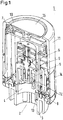
- Fig.1 shows a heat exchanger thermostat arrangement 1 for a valve of a heat exchanger (valve and heat exchanger are not shown for purpose of clarity).
- the thermostat arrangement 1 comprises a valve coupling zone 2.
- the valve coupling zone 2 is defined as a socket adapted to couple the thermostat arrangement 1 to the valve.
- the valve coupling zone 2 comprises an inner wall 3 which forms a cavity 4.
- the cavity 4 is adapted to house a valve housing (not shown) of the valve.
- An actuator 5 driven by a gear work 6 is adapted to actuate a valve element in the valve housing and to adjust the opening degree of the valve.
- the thermostat arrangement 1 comprises furthermore a first temperature sensor 7 having a first distance with respect to the valve coupling zone 2 and a second temperature sensor 8 having a second distance with respect to the valve coupling zone 2, the second distance being different from the first distance.
- the first distance is larger than the second distance. Therefore, the first temperature sensor can be considered as room temperature sensor 7 and the second temperature sensor can be considered as a valve temperature sensor 8.
- a third temperature sensor 9 may be used having a third distance with respect to the valve coupling zone 2, the third distance being different from the first distance and from the second distance.
- the room temperature sensor 7 is arranged in an opening 10 of the thermostat arrangement 1, and offset from a rotational axis of a handle 11 of the thermostat arrangement 1. Therefore, the room temperature sensor 7 will mainly measure an ambient air temperature or room temperature.
- the valve temperature sensor 8 is arranged at the socket 4 near the valve coupling zone 2 it will mainly measure the valve temperature or a temperature of a heat carrying fluid which is controlled by the valve.
- the third temperature sensor 9 can be arranged equidistant from the room temperature sensor 7 and the valve temperature sensor 8.
- a support element 12 is provided next to a side wall of the thermostat arrangement 1 radially surrounding the rotational axis of the handle 11.
- the support element 12 can be in form of a PCB (Printed Circuit Board).
- the support element 12 is also a PCB of a display 14 of the thermostat arrangement 1 and carries a controller.
- the controller comprises a temperature forecast generator as will be described below in connection with Fig. 2 and 3 .
- a gap 13 for air convection and heat radiation is provided in the thermostat arrangement 1.
- the room temperature sensor 7 in the opening 10 is covered by a plastic shield 15. This helps in shielding the room temperature sensor 7 from mechanical influence and heater radiation or sunlight heat.
- Fig. 2 schematically shows elements which are used to obtain a room temperature forecast.
- the valve temperature sensor 8 is connected to a filter 16.
- the filter 16 comprises an output 17 at which an actual heat related value is provided.
- This output 17 is connected to a heat development observation section 18.
- the heat development observation section 18 comprises a unit delay 19.
- the unit delay 19 stores at least the previously obtained heat related value from the output 17 of the filter 16.
- the heat development observation section 18 is connected to a unit 20 forming a difference between the actual heat related value from the output 17 of the filter 16 and the previously obtained heat related value from the unit delay 19.
- the difference is supplied to a gain section 21 in which a gain is added. Another possibility would be that the gain section 21 multiplies the output of the unit 20 with a constant factor.
- the output of the gain section 21 is a forecast temperature which is supplied to an adder 22.
- the adder 22 receives the actual room temperature from the room temperature sensor 7. The addition of the forecast temperature and the actual room cast temperature leads to a room forecast temperature 23.
- Fig. 3 shows three diagrams each showing one or two temperatures over time.
- the first diagram on top shows the valve temperature T valve obtained by the valve temperature sensor 8 in a full line.
- the filtered temperature T valve, filtered is shown in a dashed line.
- a middle diagram shows the forecast temperature and the lower diagram shows a room temperature T front in a full line and the room temperature forecast T front + forecast addition in a dashed line.
- the data or value from the temperature sensor closest to the valve i.e. from the valve temperature sensor 8 is used to make a forecast for the room temperature. This is in principle done in the way that the room temperature estimate is corrected with a gradient from the valve temperature sensor 8.
- the flow of heat carrying fluid through the valve or generally through the heat exchanger is, for example, dependent on the differential pressure over the valve.
- the valve When the valve is open there might be a variation in the flow and therefore it is difficult to exactly determine how much water or other heat carrying fluid is flowing through the valve. This can again lead to, for example, over-shoot of the room temperature because too much heat carrying fluid has passed through the valve.
- the temperature of the valve can also be replaced by the temperature of the heat exchanger.
- the temperature of the valve and/or the temperature of the heat exchanger can also be detected remotely, for example by IR-sensor which "looks" at the infrared radiation from the heat exchanger.
- heat sensor is part of the controller. It could also be built with discrete electronics.
- the information about the heat supplied to the heat exchanger can also be obtained by means of a flow sensor. When looking at the changes in the flow this would lead to a measure for how much heat is supplied to the heat exchanger.
- a calculation of the room temperature forecast can, for example, be made once every minute and in this example the gain of the gain section 21 could be 6 so that there is a curve looking at "6 minutes". If there is, for example, an actual valve temperature of 45 degree (or a corresponding value) and the last valve temperature measurement was 44 degrees, then there is a difference of 1 degree outputted at the unit 20. With a gain of 6 there are 7 degrees as the forecast and if the temperature measured by the room temperature sensor 7 is 22 degree, then the forecast room temperature is 29 degrees until the next measurement. Based on these 29 degrees the actuator 9 can change the opening degree of the valve.
Landscapes
- Engineering & Computer Science (AREA)
- Physics & Mathematics (AREA)
- General Engineering & Computer Science (AREA)
- Mechanical Engineering (AREA)
- Thermal Sciences (AREA)
- Chemical & Material Sciences (AREA)
- Combustion & Propulsion (AREA)
- Life Sciences & Earth Sciences (AREA)
- Atmospheric Sciences (AREA)
- Biodiversity & Conservation Biology (AREA)
- Ecology (AREA)
- Environmental & Geological Engineering (AREA)
- Environmental Sciences (AREA)
- Fluid Mechanics (AREA)
- General Physics & Mathematics (AREA)
- Automation & Control Theory (AREA)
- Steam Or Hot-Water Central Heating Systems (AREA)
Abstract
Description
- The present invention relates to a heat exchanger thermostat arrangement comprising a valve, a room temperature sensor, a controller, and a heat sensor.
- Furthermore, the invention relates to a method for controlling a heat exchanger valve in which an opening degree of the valve is adjusted based on a temperature value.
- In the following a radiator and a radiator valve are used for describing an embodiment of the invention. However, the invention can be used with other heat exchangers as well, for example a floor heating.
- A heat exchanger thermostat arrangement is generally used to adjust a room temperature. The actual room temperature should be as close as possible to a set-value of the room temperature. When the actual room temperature is lower than the set-value the valve is opened to allow a larger flow of heat carrying fluid through the heat exchanger. This will increase the room temperature. When the actual room temperature has reached the set-value the opening degree of the valve is decreased and the temperature decreases as well. Such a temperature control can lead, for example, to an over-shoot of the room temperature or to an undulation of the room temperature.
- The object underlying the invention is to have a good control of the room temperature.
- This object is solved with a heat exchanger thermostat arrangement as described at the outset in that the controller comprises a temperature forecast generator making a temperature forecast based on a heat related value received from the heat sensor.
- The heat sensor is different from the room temperature sensor and allows an indication of the heat supplied to the heat exchanger. This information can be used to make a forecast of the room temperature. The forecasted room temperature is a "view in the future", i.e. an estimation of the room temperature which would develop when the actual conditions of the valve would remain unchanged. In this way, a regulation can be much faster.
- In an embodiment of the invention the temperature forecast generator receives a room temperature related value from the room temperature sensor. The actual room temperature can be used in addition to generate the temperature forecast.
- In an embodiment of the invention the temperature forecast generator comprises a heat development observation section in which a difference between an actual heat related value and at least one previously obtained heat related value is obtained. In this way, the temperature forecast generator can take into account a function of supplied heat over time which in turn allows a temperature forecast.
- In an embodiment of the invention the heat development observation section is connected to a gain section. In the gain section, an output of the heat development observation section can be amplified by multiplying it with a gain factor or by a gain being added.
- In an embodiment of the invention the heat development observation section is connected to an adder adding an actual room temperature value and a value from the heat development observation section. This is a simple way to use the actual room temperature value as well.
- In an embodiment of the invention the heat sensor is a valve temperature sensor. The valve temperature sensor is a sensor sensing the temperature of the valve itself. It is arranged close to a connection between the valve and the heat exchanger. In this way, it is possible to estimate the future room temperature based on a gradient from the valve temperature sensor.
- In an embodiment of the invention which can be used alternatively or additionally the heat sensor is a heat exchanger temperature sensor. The heat exchanger temperature sensor senses the temperature of the heat exchanger, in particular the temperature near an inlet of the heat exchanger.
- In both cases the heat sensor can be a remote sensor sensing the heat of the valve or of the heat exchanger from a remote position. For this purpose, for example, an IR-sensor can be used.
- In an alternative embodiment, the heat sensor is a flow sensor. The flow sensor measures the flow of the heat carrying fluid flowing through the heat exchanger. This information can as well be used to determine or estimate the amount of heat.
- The object is solved in a method as described at the outset in that the temperature value comprises a temperature forecast value which is based on a heat related value obtained from a heat sensor.
- As described above in connection with the heat exchanger thermostat arrangement, the temperature forecast value is an estimation of a temperature which would develop if the actual conditions of the valve would remain unchanged. This estimation can be used to "correct" the opening degree of the valve at an earlier stage so that an over-shoot of the temperature can be avoided and other disturbances can be eliminated before they can affect the room temperature.
- In an embodiment, the temperature value is additionally based on an actual room temperature. In this case, for example, the temperature forecast value is only a difference between the actual room temperature and an estimated room temperature.
- In an embodiment of the invention the temperature forecast value is related to a difference between an actual heat related value and a previously obtained heat related value. The method takes into account the heat development.
- An embodiment of the invention will now be described in more detail with reference to the drawing, wherein:
- Fig. 1
- shows a perspective view of a cross section through a heat exchanger thermostat arrangement according to an embodiment of the invention,
- Fig. 2
- shows a schematic diagram of a way to obtain a room temperature forecast, and
- Fig. 3
- shows some functions of temperature over time.
-
Fig.1 shows a heatexchanger thermostat arrangement 1 for a valve of a heat exchanger (valve and heat exchanger are not shown for purpose of clarity). Thethermostat arrangement 1 comprises avalve coupling zone 2. Thevalve coupling zone 2 is defined as a socket adapted to couple thethermostat arrangement 1 to the valve. Thevalve coupling zone 2 comprises aninner wall 3 which forms a cavity 4. The cavity 4 is adapted to house a valve housing (not shown) of the valve. Anactuator 5 driven by agear work 6 is adapted to actuate a valve element in the valve housing and to adjust the opening degree of the valve. - The
thermostat arrangement 1 comprises furthermore afirst temperature sensor 7 having a first distance with respect to thevalve coupling zone 2 and asecond temperature sensor 8 having a second distance with respect to thevalve coupling zone 2, the second distance being different from the first distance. In this embodiment, the first distance is larger than the second distance. Therefore, the first temperature sensor can be considered asroom temperature sensor 7 and the second temperature sensor can be considered as avalve temperature sensor 8. - A
third temperature sensor 9 may be used having a third distance with respect to thevalve coupling zone 2, the third distance being different from the first distance and from the second distance. - The
room temperature sensor 7 is arranged in anopening 10 of thethermostat arrangement 1, and offset from a rotational axis of ahandle 11 of thethermostat arrangement 1. Therefore, theroom temperature sensor 7 will mainly measure an ambient air temperature or room temperature. As thevalve temperature sensor 8 is arranged at the socket 4 near thevalve coupling zone 2 it will mainly measure the valve temperature or a temperature of a heat carrying fluid which is controlled by the valve. - The
third temperature sensor 9 can be arranged equidistant from theroom temperature sensor 7 and thevalve temperature sensor 8. To allow an easy fixing of thethird temperature sensor 9 to thethermostat arrangement 1, asupport element 12 is provided next to a side wall of thethermostat arrangement 1 radially surrounding the rotational axis of thehandle 11. Thesupport element 12 can be in form of a PCB (Printed Circuit Board). Thesupport element 12 is also a PCB of adisplay 14 of thethermostat arrangement 1 and carries a controller. - The controller comprises a temperature forecast generator as will be described below in connection with
Fig. 2 and 3 . - A
gap 13 for air convection and heat radiation is provided in thethermostat arrangement 1. - The
room temperature sensor 7 in theopening 10 is covered by aplastic shield 15. This helps in shielding theroom temperature sensor 7 from mechanical influence and heater radiation or sunlight heat. -
Fig. 2 schematically shows elements which are used to obtain a room temperature forecast. - The
valve temperature sensor 8 is connected to afilter 16. Thefilter 16 comprises anoutput 17 at which an actual heat related value is provided. Thisoutput 17 is connected to a heatdevelopment observation section 18. The heatdevelopment observation section 18 comprises aunit delay 19. The unit delay 19 stores at least the previously obtained heat related value from theoutput 17 of thefilter 16. The heatdevelopment observation section 18 is connected to aunit 20 forming a difference between the actual heat related value from theoutput 17 of thefilter 16 and the previously obtained heat related value from theunit delay 19. The difference is supplied to a gain section 21 in which a gain is added. Another possibility would be that the gain section 21 multiplies the output of theunit 20 with a constant factor. The output of the gain section 21 is a forecast temperature which is supplied to anadder 22. Theadder 22 receives the actual room temperature from theroom temperature sensor 7. The addition of the forecast temperature and the actual room cast temperature leads to aroom forecast temperature 23. -
Fig. 3 shows three diagrams each showing one or two temperatures over time. - The first diagram on top shows the valve temperature Tvalve obtained by the
valve temperature sensor 8 in a full line. The filtered temperature Tvalve, filtered is shown in a dashed line. - A middle diagram shows the forecast temperature and the lower diagram shows a room temperature Tfront in a full line and the room temperature forecast Tfront + forecast addition in a dashed line.
- In principle, the data or value from the temperature sensor closest to the valve, i.e. from the
valve temperature sensor 8 is used to make a forecast for the room temperature. This is in principle done in the way that the room temperature estimate is corrected with a gradient from thevalve temperature sensor 8. - The flow of heat carrying fluid through the valve or generally through the heat exchanger is, for example, dependent on the differential pressure over the valve. When the valve is open there might be a variation in the flow and therefore it is difficult to exactly determine how much water or other heat carrying fluid is flowing through the valve. This can again lead to, for example, over-shoot of the room temperature because too much heat carrying fluid has passed through the valve.
- When a temperature forecast is made, which is based on a measurement of the heat supplied to the heat exchanger, the regulation is "told" much sooner if the flow is changed so that over- or undershoot can be reduced. This also compensates for changes in the forward water temperature so that disturbances can be eliminated before they can affect the room temperature.
- The temperature of the valve can also be replaced by the temperature of the heat exchanger. The temperature of the valve and/or the temperature of the heat exchanger can also be detected remotely, for example by IR-sensor which "looks" at the infrared radiation from the heat exchanger.
- It is therefore not necessary that heat sensor is part of the controller. It could also be built with discrete electronics.
- The information about the heat supplied to the heat exchanger can also be obtained by means of a flow sensor. When looking at the changes in the flow this would lead to a measure for how much heat is supplied to the heat exchanger.
- A calculation of the room temperature forecast can, for example, be made once every minute and in this example the gain of the gain section 21 could be 6 so that there is a curve looking at "6 minutes". If there is, for example, an actual valve temperature of 45 degree (or a corresponding value) and the last valve temperature measurement was 44 degrees, then there is a difference of 1 degree outputted at the
unit 20. With a gain of 6 there are 7 degrees as the forecast and if the temperature measured by theroom temperature sensor 7 is 22 degree, then the forecast room temperature is 29 degrees until the next measurement. Based on these 29 degrees theactuator 9 can change the opening degree of the valve.
Claims (12)
- Heat exchanger thermostat arrangement (1) comprising a valve, a room temperature sensor (7), a controller, and a heat sensor (8), characterized in that the controller comprises a temperature forecast generator making a temperature forecast based on a heat related value received from the heat sensor (8).
- Heat exchanger thermostat arrangement according to claim 1, characterized in that the temperature forecast generator receives a room temperature related value from the room temperature sensor (7).
- Heat exchanger thermostat arrangement according to claim 1 or 2, characterized in that the temperature forecast generator comprises a heat development observation section (18) in which a difference between an actual heat related value and at least one previously obtained heat related value is obtained.
- Heat exchanger thermostat arrangement according to claim 3, characterized in that the heat development observation section (18) is connected to a gain section (21).
- Heat exchanger thermostat arrangement according to claim 3 or 4, characterized in that the heat development observation section (18) is connected to an adder (22) adding an actual room temperature value and a value from the heat development observation section (18).
- Heat exchanger thermostat arrangement according to any of claims 1 to 5, characterized in that the heat sensor is a valve temperature sensor (8).
- Heat exchanger thermostat arrangement according to any of claims 1 to 5, characterized in that the heat sensor is a heat exchanger temperature sensor.
- Heat exchanger thermostat arrangement according to claim 6 or 7, characterized in that the heat sensor is a remote sensor.
- Heat exchanger thermostat arrangement according to any of claims 1 to 5, characterized in that the heat sensor is a flow sensor.
- Method for controlling a heat exchanger valve in which an opening degree of the valve is adjusted based on a temperature value, characterized in that the temperature value comprises a temperature forecast value which is based on a heat related value obtained from a heat sensor.
- Method according to claim 10, characterized in that the temperature value is additionally based on an actual room temperature.
- Method according to claim 10 or 11, characterized in that the temperature forecast value is related to a difference between an actual heat related value and a previously obtained heat related value.
Priority Applications (3)
| Application Number | Priority Date | Filing Date | Title |
|---|---|---|---|
| EP17177307.0A EP3418849B1 (en) | 2017-06-22 | 2017-06-22 | Heat exchanger thermostat arrangement and method for controlling a heat exchanger valve |
| DK17177307.0T DK3418849T3 (en) | 2017-06-22 | 2017-06-22 | Heat exchanger thermostat device and method for controlling heat exchanger valve |
| PL17177307T PL3418849T3 (en) | 2017-06-22 | 2017-06-22 | The system of the heat exchanger thermostat and the method of controlling the heat exchanger valve |
Applications Claiming Priority (1)
| Application Number | Priority Date | Filing Date | Title |
|---|---|---|---|
| EP17177307.0A EP3418849B1 (en) | 2017-06-22 | 2017-06-22 | Heat exchanger thermostat arrangement and method for controlling a heat exchanger valve |
Publications (2)
| Publication Number | Publication Date |
|---|---|
| EP3418849A1 true EP3418849A1 (en) | 2018-12-26 |
| EP3418849B1 EP3418849B1 (en) | 2020-01-15 |
Family
ID=59152684
Family Applications (1)
| Application Number | Title | Priority Date | Filing Date |
|---|---|---|---|
| EP17177307.0A Active EP3418849B1 (en) | 2017-06-22 | 2017-06-22 | Heat exchanger thermostat arrangement and method for controlling a heat exchanger valve |
Country Status (3)
| Country | Link |
|---|---|
| EP (1) | EP3418849B1 (en) |
| DK (1) | DK3418849T3 (en) |
| PL (1) | PL3418849T3 (en) |
Cited By (1)
| Publication number | Priority date | Publication date | Assignee | Title |
|---|---|---|---|---|
| EP4016236A1 (en) * | 2020-12-18 | 2022-06-22 | Danfoss A/S | Method and system for keeping fluid flow constant in a radiator |
Citations (4)
| Publication number | Priority date | Publication date | Assignee | Title |
|---|---|---|---|---|
| WO2007046792A1 (en) * | 2005-10-18 | 2007-04-26 | Carrier Corporation | System and method for control of heat pump operation |
| WO2007090405A2 (en) * | 2006-02-10 | 2007-08-16 | Danfoss A/S | Control of a system with a large thermal capacity |
| WO2009024746A2 (en) * | 2007-08-21 | 2009-02-26 | Chalmor Limited | Thermostatic control device |
| DE102015107237A1 (en) * | 2015-05-08 | 2016-11-10 | Hochschule für Technik und Wirtschaft Dresden | Arrangement and method for controlling a room temperature |
-
2017
- 2017-06-22 DK DK17177307.0T patent/DK3418849T3/en active
- 2017-06-22 PL PL17177307T patent/PL3418849T3/en unknown
- 2017-06-22 EP EP17177307.0A patent/EP3418849B1/en active Active
Patent Citations (4)
| Publication number | Priority date | Publication date | Assignee | Title |
|---|---|---|---|---|
| WO2007046792A1 (en) * | 2005-10-18 | 2007-04-26 | Carrier Corporation | System and method for control of heat pump operation |
| WO2007090405A2 (en) * | 2006-02-10 | 2007-08-16 | Danfoss A/S | Control of a system with a large thermal capacity |
| WO2009024746A2 (en) * | 2007-08-21 | 2009-02-26 | Chalmor Limited | Thermostatic control device |
| DE102015107237A1 (en) * | 2015-05-08 | 2016-11-10 | Hochschule für Technik und Wirtschaft Dresden | Arrangement and method for controlling a room temperature |
Cited By (1)
| Publication number | Priority date | Publication date | Assignee | Title |
|---|---|---|---|---|
| EP4016236A1 (en) * | 2020-12-18 | 2022-06-22 | Danfoss A/S | Method and system for keeping fluid flow constant in a radiator |
Also Published As
| Publication number | Publication date |
|---|---|
| EP3418849B1 (en) | 2020-01-15 |
| PL3418849T3 (en) | 2020-06-29 |
| DK3418849T3 (en) | 2020-04-06 |
Similar Documents
| Publication | Publication Date | Title |
|---|---|---|
| DK1936290T3 (en) | A method and device for detecting the hydraulic state for a heating installation | |
| US10533763B2 (en) | Controller of air-conditioning system and method for controlling air-conditioning system | |
| KR101730683B1 (en) | A method and apparatus for regulating the temperature of a plurality of rooms in a building | |
| RU2573378C2 (en) | Device and method of valve opening control for hvac system | |
| CN105683661B (en) | Method for adapting a heating curve | |
| US20100095906A1 (en) | Water heater with partially thermally isolated temperature sensor | |
| EP3364116B1 (en) | Method for controlling a heat pump system and heat pump system | |
| WO2015031327A1 (en) | Flow-control valve system and method | |
| JP6324628B2 (en) | Heat pump utilization system control device and heat pump utilization system including the same | |
| US7930937B2 (en) | Detection device making it possible to measure the quantity of hot water remaining in a storage reservoir | |
| EP2846103B1 (en) | Regulation method for regulating an air conditioning system | |
| EP3418849B1 (en) | Heat exchanger thermostat arrangement and method for controlling a heat exchanger valve | |
| EP2443408B1 (en) | Device for metering the heat energy emitted by radiators, convector heaters or the like, particulary for the apportionment of heating and/or conditioning costs | |
| EP4163554B1 (en) | Regulation system for a thermo-hydraulic circuit and control method | |
| HUP0101993A2 (en) | Equipment for detecting heat rejection of a heater body and for room temperature control | |
| EP3816596B1 (en) | Regulation of rate of temperature change for a dry block calibrator | |
| EP3246782B1 (en) | Control means for a valve arrangement, valve arrangement, and method for monitoring temperatures with a control means for a valve arrangement | |
| KR101691934B1 (en) | Building automatic control system using 3D virtual reality | |
| CN111219780A (en) | Use room temperature estimates to control heating equipment | |
| HUP0200690A2 (en) | Method and device for controlling of room temperature | |
| EP3382490B1 (en) | Method for controlling a hydronic heating system in multiple rooms | |
| KR102463002B1 (en) | Flow control heating management system and method thereby | |
| RU2608633C1 (en) | Steam boiler water level control device | |
| EP4141608B1 (en) | Valve arrangement and method for operating a valve | |
| EP3657078B1 (en) | Method of measurement of power output of heat exchangers |
Legal Events
| Date | Code | Title | Description |
|---|---|---|---|
| PUAI | Public reference made under article 153(3) epc to a published international application that has entered the european phase |
Free format text: ORIGINAL CODE: 0009012 |
|
| STAA | Information on the status of an ep patent application or granted ep patent |
Free format text: STATUS: THE APPLICATION HAS BEEN PUBLISHED |
|
| AK | Designated contracting states |
Kind code of ref document: A1 Designated state(s): AL AT BE BG CH CY CZ DE DK EE ES FI FR GB GR HR HU IE IS IT LI LT LU LV MC MK MT NL NO PL PT RO RS SE SI SK SM TR |
|
| AX | Request for extension of the european patent |
Extension state: BA ME |
|
| STAA | Information on the status of an ep patent application or granted ep patent |
Free format text: STATUS: REQUEST FOR EXAMINATION WAS MADE |
|
| 17P | Request for examination filed |
Effective date: 20190625 |
|
| RBV | Designated contracting states (corrected) |
Designated state(s): AL AT BE BG CH CY CZ DE DK EE ES FI FR GB GR HR HU IE IS IT LI LT LU LV MC MK MT NL NO PL PT RO RS SE SI SK SM TR |
|
| GRAP | Despatch of communication of intention to grant a patent |
Free format text: ORIGINAL CODE: EPIDOSNIGR1 |
|
| STAA | Information on the status of an ep patent application or granted ep patent |
Free format text: STATUS: GRANT OF PATENT IS INTENDED |
|
| RIC1 | Information provided on ipc code assigned before grant |
Ipc: F24D 19/10 20060101ALN20190809BHEP Ipc: G05D 23/19 20060101AFI20190809BHEP |
|
| INTG | Intention to grant announced |
Effective date: 20190905 |
|
| GRAS | Grant fee paid |
Free format text: ORIGINAL CODE: EPIDOSNIGR3 |
|
| GRAA | (expected) grant |
Free format text: ORIGINAL CODE: 0009210 |
|
| STAA | Information on the status of an ep patent application or granted ep patent |
Free format text: STATUS: THE PATENT HAS BEEN GRANTED |
|
| AK | Designated contracting states |
Kind code of ref document: B1 Designated state(s): AL AT BE BG CH CY CZ DE DK EE ES FI FR GB GR HR HU IE IS IT LI LT LU LV MC MK MT NL NO PL PT RO RS SE SI SK SM TR |
|
| REG | Reference to a national code |
Ref country code: CH Ref legal event code: EP Ref country code: GB Ref legal event code: FG4D |
|
| REG | Reference to a national code |
Ref country code: IE Ref legal event code: FG4D |
|
| REG | Reference to a national code |
Ref country code: DE Ref legal event code: R096 Ref document number: 602017010845 Country of ref document: DE |
|
| REG | Reference to a national code |
Ref country code: AT Ref legal event code: REF Ref document number: 1225711 Country of ref document: AT Kind code of ref document: T Effective date: 20200215 |
|
| REG | Reference to a national code |
Ref country code: DK Ref legal event code: T3 Effective date: 20200402 |
|
| REG | Reference to a national code |
Ref country code: NL Ref legal event code: MP Effective date: 20200115 |
|
| REG | Reference to a national code |
Ref country code: LT Ref legal event code: MG4D |
|
| PG25 | Lapsed in a contracting state [announced via postgrant information from national office to epo] |
Ref country code: NO Free format text: LAPSE BECAUSE OF FAILURE TO SUBMIT A TRANSLATION OF THE DESCRIPTION OR TO PAY THE FEE WITHIN THE PRESCRIBED TIME-LIMIT Effective date: 20200415 Ref country code: RS Free format text: LAPSE BECAUSE OF FAILURE TO SUBMIT A TRANSLATION OF THE DESCRIPTION OR TO PAY THE FEE WITHIN THE PRESCRIBED TIME-LIMIT Effective date: 20200115 Ref country code: NL Free format text: LAPSE BECAUSE OF FAILURE TO SUBMIT A TRANSLATION OF THE DESCRIPTION OR TO PAY THE FEE WITHIN THE PRESCRIBED TIME-LIMIT Effective date: 20200115 Ref country code: FI Free format text: LAPSE BECAUSE OF FAILURE TO SUBMIT A TRANSLATION OF THE DESCRIPTION OR TO PAY THE FEE WITHIN THE PRESCRIBED TIME-LIMIT Effective date: 20200115 Ref country code: PT Free format text: LAPSE BECAUSE OF FAILURE TO SUBMIT A TRANSLATION OF THE DESCRIPTION OR TO PAY THE FEE WITHIN THE PRESCRIBED TIME-LIMIT Effective date: 20200607 |
|
| PG25 | Lapsed in a contracting state [announced via postgrant information from national office to epo] |
Ref country code: IS Free format text: LAPSE BECAUSE OF FAILURE TO SUBMIT A TRANSLATION OF THE DESCRIPTION OR TO PAY THE FEE WITHIN THE PRESCRIBED TIME-LIMIT Effective date: 20200515 Ref country code: GR Free format text: LAPSE BECAUSE OF FAILURE TO SUBMIT A TRANSLATION OF THE DESCRIPTION OR TO PAY THE FEE WITHIN THE PRESCRIBED TIME-LIMIT Effective date: 20200416 Ref country code: HR Free format text: LAPSE BECAUSE OF FAILURE TO SUBMIT A TRANSLATION OF THE DESCRIPTION OR TO PAY THE FEE WITHIN THE PRESCRIBED TIME-LIMIT Effective date: 20200115 Ref country code: LV Free format text: LAPSE BECAUSE OF FAILURE TO SUBMIT A TRANSLATION OF THE DESCRIPTION OR TO PAY THE FEE WITHIN THE PRESCRIBED TIME-LIMIT Effective date: 20200115 Ref country code: SE Free format text: LAPSE BECAUSE OF FAILURE TO SUBMIT A TRANSLATION OF THE DESCRIPTION OR TO PAY THE FEE WITHIN THE PRESCRIBED TIME-LIMIT Effective date: 20200115 Ref country code: BG Free format text: LAPSE BECAUSE OF FAILURE TO SUBMIT A TRANSLATION OF THE DESCRIPTION OR TO PAY THE FEE WITHIN THE PRESCRIBED TIME-LIMIT Effective date: 20200415 |
|
| REG | Reference to a national code |
Ref country code: DE Ref legal event code: R097 Ref document number: 602017010845 Country of ref document: DE |
|
| PG25 | Lapsed in a contracting state [announced via postgrant information from national office to epo] |
Ref country code: EE Free format text: LAPSE BECAUSE OF FAILURE TO SUBMIT A TRANSLATION OF THE DESCRIPTION OR TO PAY THE FEE WITHIN THE PRESCRIBED TIME-LIMIT Effective date: 20200115 Ref country code: ES Free format text: LAPSE BECAUSE OF FAILURE TO SUBMIT A TRANSLATION OF THE DESCRIPTION OR TO PAY THE FEE WITHIN THE PRESCRIBED TIME-LIMIT Effective date: 20200115 Ref country code: LT Free format text: LAPSE BECAUSE OF FAILURE TO SUBMIT A TRANSLATION OF THE DESCRIPTION OR TO PAY THE FEE WITHIN THE PRESCRIBED TIME-LIMIT Effective date: 20200115 Ref country code: CZ Free format text: LAPSE BECAUSE OF FAILURE TO SUBMIT A TRANSLATION OF THE DESCRIPTION OR TO PAY THE FEE WITHIN THE PRESCRIBED TIME-LIMIT Effective date: 20200115 Ref country code: SK Free format text: LAPSE BECAUSE OF FAILURE TO SUBMIT A TRANSLATION OF THE DESCRIPTION OR TO PAY THE FEE WITHIN THE PRESCRIBED TIME-LIMIT Effective date: 20200115 Ref country code: RO Free format text: LAPSE BECAUSE OF FAILURE TO SUBMIT A TRANSLATION OF THE DESCRIPTION OR TO PAY THE FEE WITHIN THE PRESCRIBED TIME-LIMIT Effective date: 20200115 Ref country code: SM Free format text: LAPSE BECAUSE OF FAILURE TO SUBMIT A TRANSLATION OF THE DESCRIPTION OR TO PAY THE FEE WITHIN THE PRESCRIBED TIME-LIMIT Effective date: 20200115 |
|
| REG | Reference to a national code |
Ref country code: AT Ref legal event code: MK05 Ref document number: 1225711 Country of ref document: AT Kind code of ref document: T Effective date: 20200115 |
|
| PLBE | No opposition filed within time limit |
Free format text: ORIGINAL CODE: 0009261 |
|
| STAA | Information on the status of an ep patent application or granted ep patent |
Free format text: STATUS: NO OPPOSITION FILED WITHIN TIME LIMIT |
|
| 26N | No opposition filed |
Effective date: 20201016 |
|
| PG25 | Lapsed in a contracting state [announced via postgrant information from national office to epo] |
Ref country code: IT Free format text: LAPSE BECAUSE OF FAILURE TO SUBMIT A TRANSLATION OF THE DESCRIPTION OR TO PAY THE FEE WITHIN THE PRESCRIBED TIME-LIMIT Effective date: 20200115 Ref country code: AT Free format text: LAPSE BECAUSE OF FAILURE TO SUBMIT A TRANSLATION OF THE DESCRIPTION OR TO PAY THE FEE WITHIN THE PRESCRIBED TIME-LIMIT Effective date: 20200115 Ref country code: MC Free format text: LAPSE BECAUSE OF FAILURE TO SUBMIT A TRANSLATION OF THE DESCRIPTION OR TO PAY THE FEE WITHIN THE PRESCRIBED TIME-LIMIT Effective date: 20200115 |
|
| PG25 | Lapsed in a contracting state [announced via postgrant information from national office to epo] |
Ref country code: SI Free format text: LAPSE BECAUSE OF FAILURE TO SUBMIT A TRANSLATION OF THE DESCRIPTION OR TO PAY THE FEE WITHIN THE PRESCRIBED TIME-LIMIT Effective date: 20200115 |
|
| PG25 | Lapsed in a contracting state [announced via postgrant information from national office to epo] |
Ref country code: LU Free format text: LAPSE BECAUSE OF NON-PAYMENT OF DUE FEES Effective date: 20200622 |
|
| REG | Reference to a national code |
Ref country code: BE Ref legal event code: MM Effective date: 20200630 |
|
| PG25 | Lapsed in a contracting state [announced via postgrant information from national office to epo] |
Ref country code: IE Free format text: LAPSE BECAUSE OF NON-PAYMENT OF DUE FEES Effective date: 20200622 |
|
| PG25 | Lapsed in a contracting state [announced via postgrant information from national office to epo] |
Ref country code: BE Free format text: LAPSE BECAUSE OF NON-PAYMENT OF DUE FEES Effective date: 20200630 |
|
| PG25 | Lapsed in a contracting state [announced via postgrant information from national office to epo] |
Ref country code: TR Free format text: LAPSE BECAUSE OF FAILURE TO SUBMIT A TRANSLATION OF THE DESCRIPTION OR TO PAY THE FEE WITHIN THE PRESCRIBED TIME-LIMIT Effective date: 20200115 Ref country code: MT Free format text: LAPSE BECAUSE OF FAILURE TO SUBMIT A TRANSLATION OF THE DESCRIPTION OR TO PAY THE FEE WITHIN THE PRESCRIBED TIME-LIMIT Effective date: 20200115 Ref country code: CY Free format text: LAPSE BECAUSE OF FAILURE TO SUBMIT A TRANSLATION OF THE DESCRIPTION OR TO PAY THE FEE WITHIN THE PRESCRIBED TIME-LIMIT Effective date: 20200115 |
|
| PG25 | Lapsed in a contracting state [announced via postgrant information from national office to epo] |
Ref country code: MK Free format text: LAPSE BECAUSE OF FAILURE TO SUBMIT A TRANSLATION OF THE DESCRIPTION OR TO PAY THE FEE WITHIN THE PRESCRIBED TIME-LIMIT Effective date: 20200115 Ref country code: AL Free format text: LAPSE BECAUSE OF FAILURE TO SUBMIT A TRANSLATION OF THE DESCRIPTION OR TO PAY THE FEE WITHIN THE PRESCRIBED TIME-LIMIT Effective date: 20200115 |
|
| P01 | Opt-out of the competence of the unified patent court (upc) registered |
Effective date: 20230617 |
|
| PGFP | Annual fee paid to national office [announced via postgrant information from national office to epo] |
Ref country code: CH Payment date: 20250701 Year of fee payment: 9 |
|
| REG | Reference to a national code |
Ref country code: CH Ref legal event code: U11 Free format text: ST27 STATUS EVENT CODE: U-0-0-U10-U11 (AS PROVIDED BY THE NATIONAL OFFICE) Effective date: 20260701 |
|
| PGFP | Annual fee paid to national office [announced via postgrant information from national office to epo] |
Ref country code: GB Payment date: 20260511 Year of fee payment: 10 Ref country code: DK Payment date: 20260611 Year of fee payment: 10 Ref country code: PL Payment date: 20260512 Year of fee payment: 10 |
|
| PGFP | Annual fee paid to national office [announced via postgrant information from national office to epo] |
Ref country code: DE Payment date: 20260506 Year of fee payment: 10 |
|
| PGFP | Annual fee paid to national office [announced via postgrant information from national office to epo] |
Ref country code: FR Payment date: 20260521 Year of fee payment: 10 |