EP3418688A1 - Information processing device, mobile object, information processing method, and computer-readable medium - Google Patents
Information processing device, mobile object, information processing method, and computer-readable medium Download PDFInfo
- Publication number
- EP3418688A1 EP3418688A1 EP18160159.2A EP18160159A EP3418688A1 EP 3418688 A1 EP3418688 A1 EP 3418688A1 EP 18160159 A EP18160159 A EP 18160159A EP 3418688 A1 EP3418688 A1 EP 3418688A1
- Authority
- EP
- European Patent Office
- Prior art keywords
- region
- scheduled
- space
- unit
- route
- Prior art date
- Legal status (The legal status is an assumption and is not a legal conclusion. Google has not performed a legal analysis and makes no representation as to the accuracy of the status listed.)
- Granted
Links
Images


Classifications
-
- G—PHYSICS
- G01—MEASURING; TESTING
- G01C—MEASURING DISTANCES, LEVELS OR BEARINGS; SURVEYING; NAVIGATION; GYROSCOPIC INSTRUMENTS; PHOTOGRAMMETRY OR VIDEOGRAMMETRY
- G01C21/00—Navigation; Navigational instruments not provided for in groups G01C1/00 - G01C19/00
- G01C21/26—Navigation; Navigational instruments not provided for in groups G01C1/00 - G01C19/00 specially adapted for navigation in a road network
- G01C21/34—Route searching; Route guidance
- G01C21/3453—Special cost functions, i.e. other than distance or default speed limit of road segments
- G01C21/3461—Preferred or disfavoured areas, e.g. dangerous zones, toll or emission zones, intersections, manoeuvre types or segments such as motorways, toll roads or ferries
-
- G—PHYSICS
- G01—MEASURING; TESTING
- G01C—MEASURING DISTANCES, LEVELS OR BEARINGS; SURVEYING; NAVIGATION; GYROSCOPIC INSTRUMENTS; PHOTOGRAMMETRY OR VIDEOGRAMMETRY
- G01C21/00—Navigation; Navigational instruments not provided for in groups G01C1/00 - G01C19/00
- G01C21/26—Navigation; Navigational instruments not provided for in groups G01C1/00 - G01C19/00 specially adapted for navigation in a road network
- G01C21/34—Route searching; Route guidance
- G01C21/3407—Route searching; Route guidance specially adapted for specific applications
- G01C21/3415—Dynamic re-routing, e.g. recalculating the route when the user deviates from calculated route or after detecting real-time traffic data or accidents
-
- G—PHYSICS
- G01—MEASURING; TESTING
- G01C—MEASURING DISTANCES, LEVELS OR BEARINGS; SURVEYING; NAVIGATION; GYROSCOPIC INSTRUMENTS; PHOTOGRAMMETRY OR VIDEOGRAMMETRY
- G01C21/00—Navigation; Navigational instruments not provided for in groups G01C1/00 - G01C19/00
- G01C21/26—Navigation; Navigational instruments not provided for in groups G01C1/00 - G01C19/00 specially adapted for navigation in a road network
- G01C21/34—Route searching; Route guidance
- G01C21/3453—Special cost functions, i.e. other than distance or default speed limit of road segments
- G01C21/3492—Special cost functions, i.e. other than distance or default speed limit of road segments employing speed data or traffic data, e.g. real-time or historical
-
- G—PHYSICS
- G06—COMPUTING OR CALCULATING; COUNTING
- G06Q—INFORMATION AND COMMUNICATION TECHNOLOGY [ICT] SPECIALLY ADAPTED FOR ADMINISTRATIVE, COMMERCIAL, FINANCIAL, MANAGERIAL OR SUPERVISORY PURPOSES; SYSTEMS OR METHODS SPECIALLY ADAPTED FOR ADMINISTRATIVE, COMMERCIAL, FINANCIAL, MANAGERIAL OR SUPERVISORY PURPOSES, NOT OTHERWISE PROVIDED FOR
- G06Q10/00—Administration; Management
- G06Q10/04—Forecasting or optimisation specially adapted for administrative or management purposes, e.g. linear programming or "cutting stock problem"
- G06Q10/047—Optimisation of routes or paths, e.g. travelling salesman problem
-
- G—PHYSICS
- G08—SIGNALLING
- G08G—TRAFFIC CONTROL SYSTEMS
- G08G1/00—Traffic control systems for road vehicles
- G08G1/16—Anti-collision systems
- G08G1/165—Anti-collision systems for passive traffic, e.g. including static obstacles, trees
Definitions
- the present disclosure relates to an information processing device, a mobile object, an information processing method, and a computer-readable medium.
- An automatic driving technique for automatically steering an automobile has been attracting attention. For example, disclosed is a technique for generating a route for avoiding collision with an object such as an obstacle. There is also disclosed a technique for randomly arranging nodes in a traveling region and searching for a route having lower traveling cost among a plurality of routes sequentially going through a plurality of nodes from a present location to a destination.
- an information processing device includes a first arrangement unit, a second arrangement unit, and a search unit.
- the first arrangement unit is configured to arrange a node in a first region not interfering with an object on a scheduled traveling route.
- the second arrangement unit is configured to arrange a node in a second region around an interference region interfering with the object.
- the search unit is configured to search for a route going through a plurality of nodes and having a moving cost from a first point to a second point on the scheduled traveling route equal to or smaller than a threshold.
- FIG. 1 is a diagram illustrating an example of a mobile object 10 according to an arrangement.
- the mobile object 10 includes an information processing device 20, an output unit 10A, a sensor 10B, an input device 10C, a power control unit 10G, and a power unit 10H.
- the information processing device 20 searches for a route of the mobile object 10 (details will be described later).
- the information processing device 20 is, for example, a special-purpose or a general-purpose computer. In the present arrangement, described is a case in which the information processing device 20 is mounted on the mobile object 10 as an example.
- the mobile object 10 is a movable object.
- the mobile object 10 is, for example, a vehicle (a motorcycle, an automobile, and a bicycle), a dolly, a robot, a ship, and a flying object (an airplane, an unmanned aerial vehicle (UAV), and the like).
- the mobile object 10 is, for example, a mobile object that travels through a driving operation performed by a person, or a mobile object that can automatically travel (autonomously travel) without a driving operation performed by a person.
- the mobile object that can automatically travel is, for example, an automatic driving vehicle.
- the mobile object 10 according to the present arrangement is described as a vehicle that can autonomously travel as an example.
- the information processing device 20 is not necessarily mounted on the mobile object 10.
- the information processing device 20 may be mounted on a stationary object.
- the stationary object is an unmovable object or an object stabilized on the ground.
- the stationary object is, for example, a guardrail, a pole, a parked vehicle, and a road sign.
- the information processing device 20 may be mounted on a cloud server that executes processing on a cloud.
- the output unit 10A outputs various pieces of information. In the present arrangement, the output unit 10A outputs output information.
- the output unit 10A has, for example, a communication function for transmitting the output information, a display function for displaying the output information, and a sound outputting function for outputting a sound indicating the output information.
- the output unit 10A includes a communication unit 10D, a display 10E, and a speaker 10F.
- the communication unit 10D communicates with an external device.
- the communication unit 10D is a VICS (registered trademark) communication circuit or a dynamic map communication circuit.
- the communication unit 10D transmits the output information to the external device.
- the communication unit 10D receives road information and the like from the external device.
- the road information includes a traffic light, a sign, surrounding buildings, a width of each lane, a center line of a lane, and the like.
- the road information may be stored in a storage unit 20B.
- the display 10E displays the output information.
- the display 10E is, for example, a known liquid crystal display (LCD), a projection device, and a light.
- the speaker 10F outputs a sound indicating the output information.
- the sensor 10B is a sensor that acquires a traveling environment of the mobile object 10.
- the traveling environment is, for example, observation information of the mobile object 10 and peripheral information of the mobile object 10.
- the sensor 10B is, for example, an outer field sensor or an inner field sensor.
- the inner field sensor is a sensor that observes the observation information.
- the observation information is information including at least acceleration of the mobile object 10.
- the observation information includes at least one of the acceleration of the mobile object 10, speed of the mobile object 10, and angular speed of the mobile object 10.
- the inner field sensor is, for example, an inertial measurement unit (IMU), an acceleration sensor, a speed sensor, and a rotary encoder.
- the IMU observes the observation information including triaxial acceleration and triaxial angular speed of the mobile object 10.
- the outer field sensor observes the peripheral information of the mobile object 10.
- the outer field sensor may be mounted on the mobile object 10, or may be mounted outside the mobile object 10 (for example, another mobile object or an external device).
- the peripheral information is information indicating a condition of surroundings of the mobile object 10.
- the surroundings of the mobile object 10 are a region within a predetermined range around the mobile object 10. This range is a range that can be observed by the outer field sensor. The range may be set in advance.
- the peripheral information is at least one of a photographed image of the surroundings of the mobile object 10 and distance information.
- the peripheral information may include location information of the mobile object 10.
- the photographed image is photographed image data obtained by photography (hereinafter, simply referred to as a photographed image in some cases).
- the distance information is information indicating a distance from the mobile object 10 to an object.
- the object is a point that can be observed by the outer field sensor in an outer field.
- the location information may be a relative position or an absolute position.
- the outer field sensor is, for example, a photographing device that obtains the photographed image by photography, a distance sensor (a millimetric wave radar, a laser sensor, and a distance image sensor), and a position sensor (Global Navigation Satellite System (GNSS), a Global Positioning System (GPS), and a wireless communication device).
- a distance sensor a millimetric wave radar, a laser sensor, and a distance image sensor
- GNSS Global Navigation Satellite System
- GPS Global Positioning System
- the photographed image is, for example, digital image data in which a pixel value is defined for each pixel, and a depth map in which a distance from the sensor 10B is defined for each pixel.
- the laser sensor is, for example, a two-dimensional Laser Imaging Detection and Ranging (LIDAR) sensor arranged in parallel with a horizontal plane, and a three-dimensional LIDAR sensor.
- LIDAR Laser Imaging Detection and Ranging
- the input device 10C receives various instructions and an input of information from a user.
- the input device 10C is, for example, a pointing device such as a mouse and a trackball, or an input device such as a keyboard.
- the input device 10C may be an input function of a touch panel that is arranged integrally with the display 10E.
- the power control unit 10G controls the power unit 10H.
- the power unit 10H is a device that is for driving and mounted on the mobile object 10.
- the power unit 10H is, for example, an engine, a motor, and a wheel.
- the power unit 10H is driven by being controlled by the power control unit 10G.
- the power control unit 10G determines a condition of the surroundings on the basis of the output information generated by the information processing device 20, information obtained from the sensor 10B, and the like, and controls an accelerator quantity, a brake quantity, a steering angle, and the like.
- the power control unit 10G controls the power unit 10H of the mobile object 10 so that the mobile object 10 moves along a route generated by the information processing device 20.
- FIG. 2 is a block diagram illustrating an example of the configuration of the mobile object 10.
- the mobile object 10 includes the information processing device 20, the output unit 10A, the sensor 10B, the input device 10C, the power control unit 10G, and the power unit 10H.
- the output unit 10A includes the communication unit 10D, the display 10E, and the speaker 10F.
- the information processing device 20, the output unit 10A, the sensor 10B, the input device 10C, and the power control unit 10G are connected to each other via a bus 10J.
- the power unit 10H is connected to the power control unit 10G.
- the information processing device 20 includes the storage unit 20B and a processing unit 20A. That is, the output unit 10A, the sensor 10B, the input device 10C, the power control unit 10G, and the storage unit 20B are connected to the processing unit 20A via the bus 10J.
- At least one of the storage unit 20B, the output unit 10A (the communication unit 10D, the display 10E, and the speaker 10F), the sensor 10B, the input device 10C, and the power control unit 10G may be connected to the processing unit 20A in a wired or wireless manner.
- At least one of the storage unit 20B, the output unit 10A (the communication unit 10D, the display 10E, and the speaker 10F), the sensor 10B, the input device 10C, and the power control unit 10G may be connected to the processing unit 20A via a network.
- the storage unit 20B stores various pieces of data.
- the storage unit 20B may be, for example, a semiconductor memory element such as a random access memory (RAM) and a flash memory, a hard disk, and an optical disc.
- the storage unit 20B may be arranged outside the information processing device 20.
- the storage unit 20B may also be arranged outside the mobile object 10.
- the storage unit 20B may be arranged in a server device installed on a cloud.
- the storage unit 20B may be a storage medium.
- the storage medium may be a storage medium that downloads a computer program or various pieces of information via a local area network (LAN) or the Internet to be stored or temporarily stored.
- the storage unit 20B may include a plurality of storage media.
- the processing unit 20A includes an acquisition unit 20C, a space constituting unit 20D, a first arrangement unit 20E, a setting unit 20F, a determination unit 20G, a deletion unit 20H, a second arrangement unit 201, a search unit 20J, a generation unit 20K, and an output control unit 20L.
- Each processing function of the processing unit 20A is stored in the storage unit 20B as a computer program that can be executed by a computer.
- the processing unit 20A is a processor that implements a functional unit corresponding to each computer program by reading out the computer program from the storage unit 20B to be executed.
- the processing unit 20A that has read out each computer program is assumed to have each functional unit illustrated in the processing unit 20A of FIG. 2 .
- FIG. 2 described is a case in which the acquisition unit 20C, the space constituting unit 20D, the first arrangement unit 20E, the setting unit 20F, the determination unit 20G, the deletion unit 20H, the second arrangement unit 20I, the search unit 20J, the generation unit 20K, and the output control unit 20L are implemented by the single processing unit 20A.
- the processing unit 20A may be configured by combining a plurality of independent processors for implementing each of functions.
- each function is implemented when each processor executes the computer program.
- each processing function is configured as a computer program and one processing circuit executes each computer program, and a case in which a specific function is mounted in a dedicated and independent program execution circuit.
- processor used in the arrangement represents, for example, a circuit of a central processing unit (CPU), a graphical processing unit (GPU), an application specific integrated circuit (ASIC), or a programmable logic device (for example, a simple programmable logic device (SPLD), a complex programmable logic device (CPLD), and a field programmable gate array (FPGA)).
- CPU central processing unit
- GPU graphical processing unit
- ASIC application specific integrated circuit
- SPLD simple programmable logic device
- CPLD complex programmable logic device
- FPGA field programmable gate array
- the processor implements a function by reading out and executing the computer program stored in the storage unit 20B.
- the computer program may be directly embedded in a circuit of the processor.
- the processor implements the function by reading out and executing the computer program embedded in the circuit.
- the acquisition unit 20C acquires a scheduled traveling route.
- the scheduled traveling route is a route over which the mobile object 10 is scheduled to pass when moving from a certain point to another point.
- the scheduled traveling route is a route over which the mobile object 10 is scheduled to pass when moving from a present location to a destination.
- the scheduled traveling route is constituted of a line passing over a road over which the mobile object 10 passes when moving from a certain point (for example, the present location of the mobile object 10) to another point (for example, the destination), and a line connecting between lines passing over different roads.
- the line passing over the road is, for example, a line passing through the center of the road to be passed (the center of a lane along a traveling direction).
- the line connecting between lines passing over different roads is, for example, a line that connects an end of a line passing over one of the roads and an end of a line passing over the other one of the roads such that a curvature draws a certain arc.
- the scheduled traveling route may further include identification information of the road to be passed (hereinafter, referred to as a road ID in some cases) and speed information indicating recommended speed of the mobile object 10.
- FIG. 3 is a schematic diagram illustrating an example of the scheduled traveling route 30.
- the scheduled traveling route 30 is represented by a line passing through the center of a traveling possible region E of a road R.
- the traveling possible region E is a region in which the mobile object 10 can travel.
- the traveling possible region E is, for example, a region along the lane on which the mobile object 10 travels.
- the scheduled traveling route 30 is represented by a group of a plurality of reference points 32 (hereinafter, referred to as a way point (WP) 32).
- the WP 32 is a point defining a position and at least one of scheduled passing time and scheduled passing speed of the mobile object 10.
- the WP 32 may be represented by a vector in place of the point.
- the position defined by the WP 32 indicates a position on a map.
- the position is, for example, represented by world coordinates.
- the position may be represented as a relative position with respect to the present position of the mobile object 10.
- the scheduled passing time defined by the WP 32 represents time at which the mobile object 10 is scheduled to pass through the position of the WP 32.
- the scheduled passing time may be relative time with respect to specific time, or time corresponding to a standard time and frequency signal.
- the scheduled passing speed defined by the WP 32 represents scheduled speed at the time when the mobile object 10 passes through the position of the WP 32.
- the scheduled passing speed may be relative speed with respect to specific speed, or may be absolute speed.
- the space constituting unit 20D arranges the scheduled traveling route 30 and the object in a search space.
- FIG. 4 is a schematic diagram illustrating a search space 40.
- the search space 40 is a space represented by a two-dimensional coordinate space (sd coordinate space), and a scheduled passing time axis (t) or a scheduled passing speed axis (v) orthogonal to the two-dimensional coordinate space.
- FIG. 4 illustrates the scheduled passing time axis (t) as an example of the coordinate axis orthogonal to the two-dimensional coordinate space.
- the two-dimensional coordinate space is a space of a two-dimensional plane along the traveling possible region E (refer to FIG. 3 ) of the mobile object 10 moving on the scheduled traveling route 30.
- the two-dimensional coordinate space is defined with an s-axis along a direction following the road of the mobile object 10 and a d-axis along a vehicle width direction of the mobile object 10.
- the s-axis and the d-axis are arranged to be orthogonal to each other.
- the s-axis is identical to an extending direction of the scheduled traveling route 30.
- the vehicle width direction is a direction orthogonal to the traveling direction of the mobile object 10.
- the scheduled passing time axis (t) orthogonal to the two-dimensional coordinate space (sd coordinate space) is a coordinate axis indicating the scheduled passing time of the mobile object 10.
- the search space 40 may be represented by using the scheduled passing speed axis (v) as a coordinate axis in place of the scheduled passing time axis (t) .
- the space constituting unit 20D may generate the search space 40 in accordance with content defined by the WP 32 constituting the scheduled traveling route 30.
- the WP 32 constituting the scheduled traveling route 30 is assumed to define the position and the scheduled passing time.
- the space constituting unit 20D may generate the search space 40 using the two-dimensional coordinate space (sd coordinate space) and the scheduled passing time axis (t) as coordinate axes.
- the WP 32 constituting the scheduled traveling route 30 is assumed to define the position and the scheduled passing speed.
- the space constituting unit 20D may generate the search space 40 using the two-dimensional coordinate space (sd coordinate space) and the scheduled passing speed axis (v) as the coordinate axes.
- the space constituting unit 20D arranges the scheduled traveling route 30 in the search space 40.
- the space constituting unit 20D arranges each WP 32 at the position indicated by the WP 32 constituting the scheduled traveling route 30, that is, a point corresponding to the scheduled traveling route 30.
- the position defined by the WP 32 may be represented by world coordinates in some cases.
- the space constituting unit 20D may convert the position coordinates represented by world coordinates and defined by the WP 32 into position coordinates represented by the sd coordinate space, and may arrange the position coordinates in the search space 40.
- the space constituting unit 20D may represent the search space 40 using an xy coordinate space or an xyz coordinate space of world coordinates in place of the sd coordinate space.
- the xy coordinate space is a two-dimensional plane orthogonal to a Z-axis direction indicating a vertical direction (height).
- FIGS. 5A and 5B are explanatory diagrams representing the two-dimensional coordinate space of the search space 40 using each of the xy coordinate space and the sd coordinate space respectively.
- FIG. 5A is an example of representing the two-dimensional coordinate space of the search space 40 with the xy coordinate space, and arranging the scheduled traveling route 30 therein.
- FIG. 5B is an example of representing the two-dimensional coordinate space of the search space 40 with the sd coordinate space, and arranging the scheduled traveling route 30 therein.
- the space constituting unit 20D further arranges an object in the search space 40.
- FIGS. 6A and 6B are explanatory diagrams of arrangement of an object 12 in the search space 40.
- FIG. 6A is an example of representing the search space 40 with the two-dimensional coordinate space (sd coordinate space).
- FIG. 6B is an example of representing the search space 40 with a three-dimensional space (sdt coordinate space).
- the object 12 is a thing that possibly obstructs traveling of the mobile object 10.
- the object 12 is, for example, an obstacle.
- the obstacle is another mobile object, a living thing such as a person and a tree, a non-living thing arranged on the ground (for example, various objects such as a sign, a traffic light, and a guardrail), and the like.
- the object 12 is not limited to the obstacle.
- the object 12 may be a non-obstacle.
- the non-obstacle is a region in which a road surface is deteriorated in the traveling possible region E.
- the region in which a road surface is deteriorated is, for example, a puddle and a depressed region.
- the non-obstacle may be a traveling-prohibited region.
- the traveling-prohibited region is a region in which traveling is prohibited represented by a rule of the road.
- the traveling-prohibited region is, for example, a region defined by a sign of no passing
- the space constituting unit 20D acquires information for specifying the object 12 from the acquisition unit 20C.
- the space constituting unit 20D acquires information indicating a position, a size, and a shape of the object 12 in a real space.
- the space constituting unit 20D may acquire information indicating the position of the object 12 in the real space and a region occupied by the object 12 in the real space.
- the space constituting unit 20D acquires information indicating the position, the size, and the shape of the object 12 from the sensor 10B via the acquisition unit 20C.
- the acquisition unit 20C derives the information indicating the position, the size, and the shape of the object 12 using a known method with a sensing result obtained by the sensor 10B.
- the space constituting unit 20D may derive the information indicating the position, the size, and the shape of the object 12 from the acquisition unit 20C.
- the space constituting unit 20D then arranges the object 12 in the search space 40 (refer to FIGS. 6A and 6B ).
- the first arrangement unit 20E arranges a node.
- the node is a point used for searching for a route (to be described later).
- the information processing device 20 searches for the route by searching for a plurality of routes connecting a plurality of nodes toward a traveling direction (details will be described later).
- FIGS. 6A and 6B The following description uses FIGS. 6A and 6B .
- the first arrangement unit 20E arranges a node N in a first region 44 of the scheduled traveling route 30. That is, the first arrangement unit 20E arranges the node N in the first region 44 of the search space 40.
- the first region 44 is a region not interfering with the object 12 on the scheduled traveling route 30.
- the first region 44 is a region other than an interference region 42 interfering with the object 12 on the scheduled traveling route 30.
- Interfering with the object 12 means that, when the mobile object 10 is assumed to travel along the scheduled traveling route 30, the mobile object 10 is brought into contact with the object 12 or travels over the object 12.
- the space constituting unit 20D sets, as the node N, the WP 32 arranged in the first region 44 as a region other than the interference region 42 among a plurality of WPs 32 constituting the scheduled traveling route 30. Due to this, among the WPs 32 constituting the scheduled traveling route 30, the WP 32 arranged in the first region 44 other than the interference region 42 is set as the node N.
- the node N arranged by the first arrangement unit 20E is referred to as a node N1.
- the setting unit 20F sets a potential field in the search space 40.
- FIGS. 7A to 7D are explanatory diagrams of an example of a potential field 43.
- the two-dimensional coordinate space (sd coordinate space) of the search space 40 is illustrated, and a p-axis indicating the potential field 43 is illustrated as a coordinate axis orthogonal to the two-dimensional coordinate space.
- the potential field 43 defines a potential value of each point in the search space 40.
- the potential value represents a risk of traveling. That is, the setting unit 20F sets a higher potential value to a point where the risk of traveling is higher, and sets a lower potential value to a point where the risk of traveling is lower.
- the setting unit 20F sets the potential field indicating a lower potential value as being closer to the scheduled traveling route 30 or more distant from the object 12.
- the setting unit 20F forms a potential line L constituted of a group of potential values in the search space 40. Specifically, the setting unit 20F defines a high potential value in a region occupied by the object 12 in the search space 40.
- the setting unit 20F sets the potential line L indicating the potential value in the search space 40.
- the setting unit 20F first defines the lowest potential value in the first region 44 not interfering with the object 12 on the scheduled traveling route 30 arranged in the search space 40. This is because the scheduled traveling route 30 is a line passing through the center of the traveling possible region E of the road R, and because the region on the scheduled traveling route 30 in which the object 12 is not present hardly deviates from the traveling possible region E.
- the setting unit 20F sets a potential value higher than that of the scheduled traveling route 30 in the region occupied by the object 12. For example, the setting unit 20F forms a first line L1 indicating a higher potential value than that of the scheduled traveling route 30 and extending in a d-axis direction in the region occupied by the object 12.
- the setting unit 20F then forms a second line L2 the potential value of which lowers with a first gradient from both ends in the d-axis direction of the first line L1 toward the outside of the object 12.
- the setting unit 20F forms a third line L3 the potential value of which increases with a third gradient from the scheduled traveling route 30 toward both ends in the d-axis direction of the traveling possible region E (for example, road shoulders).
- the gradient of the second line L2 is preferably larger than the gradient of the third line L3. This is because the mobile object 10 is preferably prevented from taking a wide turn to avoid the object 12 at the time of traveling.
- the gradient of the second line L2 is an angle formed by a straight line parallel with the d-axis and the first line L1.
- the gradient of the third line L3 is an angle formed by the straight line parallel with the d-axis and the third line L3.
- the gradients of the second line L2 and the third line L3 may be set in advance by the user.
- Each of the gradients may be a value corresponding to a side distance between the object 12 and the mobile object 10 at the time when the mobile object 10 travels and passes the object 12.
- the setting unit 20F may set the gradients so that the gradients of the second line L2 and the third line L3 are reduced as the side distance increases.
- the side distance may be set in advance by the user.
- At least one of the first line L1, the second line L2, and the third line L3 may be a straight line the gradient of which is fixed, or a curved line the gradient of which varies.
- the setting unit 20F forms the potential line L by connecting the first line L1, the second line L2, and the third line L3 to each other from the WP 32 toward both ends in the d-axis direction of the traveling possible region E for each WP 32 constituting the scheduled traveling route 30.
- the potential line L is formed by a pair of third lines L3 extending from the WP 32 toward both ends in the d-axis direction of the traveling possible region E. In this way, the setting unit 20F sets the potential field 43 by forming the potential line L.
- the setting unit 20F specifies a local minimum point 34 in the search space 40.
- the local minimum point 34 is a point indicating a local minimum peak of the potential value indicated by the potential field 43.
- FIGS. 7B to 7D illustrate a cross section obtained by cutting the potential field 43 of the search space 40 illustrated in FIG. 7A along a two-dimensional plane formed by the p-axis and the d-axis.
- FIG. 7B is an A-A' cross section of FIG. 7A.
- FIG. 7C is a B-B' cross section of FIG. 7A.
- FIG. 7D is a C-C' cross section of FIG. 7A .
- the position of the WP 32 is the local minimum point 34.
- each position shifted from the WP 32 toward both ends in the d-axis direction is the local minimum point 34. That is, on the potential line L interfering with the object 12, a plurality of local minimum points 34 are present to avoid the object 12.
- FIGS. 8A and 8B are schematic diagrams illustrating an example of a state in which the local minimum point 34 is arranged in the search space 40.
- FIG. 8A is an example of representing the search space 40 as the two-dimensional coordinate space (sd coordinate space).
- FIG. 8B is an example of representing the search space 40 as the three-dimensional space (sdt coordinate space).
- the local minimum point 34 is arranged at a local minimum peak of the potential value of the risk of traveling in the search space 40.
- the local minimum point 34 is arranged at a position avoiding the object 12 and where the risk of traveling is low.
- FIGS. 8A and 8B illustrate a case in which one object 12 is present on the scheduled traveling route 30 as an example. Accordingly, the position of the object 12 is fixed irrespective of scheduled passing time (t).
- the setting unit 20F may generate the potential field 43 for each scheduled passing time (t), and set the local minimum point 34 at a position not interfering with the moving object 12.
- the determination unit 20G determines a region to which the node N is added. That is, the determination unit 20G determines a region in which the node N is additionally arranged in addition to the node N1 arranged by the first arrangement unit 20E.
- the node N to be additionally arranged is referred to as a node N2.
- FIG. 9 is an explanatory diagram of an object a region to which the node N2 is added.
- the determination unit 20G determines the local minimum point 34, a second region 46, and a third region 48 to be regions to which the node N2 is additionally arranged.
- the second region 46 and the third region 48 are separately present.
- a deviation start scheduled space 51B and a deviation end scheduled space 51C may be taken to be long, and the second region 46 and the third region 48 may be caused to be one large region.
- the second region 46 is a region around the interference region 42 interfering with the object 12.
- the second region 46 is a region in the search space 40.
- the second region 46 is a region deviating from the scheduled traveling route 30, and is a region around the interference region 42. More specifically, the second region 46 is a region deviating from the scheduled traveling route 30, a region around the interference region 42, and a peripheral region around the local minimum point 34.
- the second region 46 is a region including the local minimum point 34.
- the second region 46 is a space different from the object 12 interfering with the scheduled traveling route 30 in at least one of the position in the two-dimensional coordinate space (sd coordinate space) and the scheduled passing time (t) or the scheduled passing speed (v), in the search space 40.
- the search space 40 is assumed to define the scheduled passing time (t) as a coordinate axis orthogonal to the sd coordinate space.
- the determination unit 20G may determine a space including the local minimum point 34 and different from the object 12 interfering with the scheduled traveling route 30 in the position in the two-dimensional coordinate space (sd coordinate space) and the scheduled passing time (t) to be the second region 46.
- the search space 40 is assumed to define the scheduled passing speed (v) as a coordinate axis orthogonal to the sd coordinate space.
- the determination unit 20G may determine a space including the local minimum point 34 and different from the object 12 interfering with the scheduled traveling route 30 in the position in the two-dimensional coordinate space (sd coordinate space) and the scheduled passing speed (v) to be the second region 46.
- the third region 48 is a region deviating from the scheduled traveling route 30 in at least one of a space before interference 50A and a space after interference 50B, in the search space 40.
- the space before interference 50A is a space before the scheduled passing time (t) at which the scheduled traveling route 30 interferes with the object 12 or the scheduled passing speed (v) at the position where the scheduled traveling route 30 interferes with the object 12, in the search space 40.
- the space after interference 50B is a space after the scheduled passing time (t) at which the scheduled traveling route 30 interferes with the object 12 or the scheduled passing speed (v) at the position where the scheduled traveling route 30 interferes with the object 12, in the search space 40.
- the region deviating from the scheduled traveling route 30 indicates a region different from the scheduled traveling route 30 in the search space 40 in at least one of the position in the two-dimensional coordinate space (sd coordinate space) and the scheduled passing time (t) or the scheduled passing speed (v).
- determination unit 20G determines a specific region in the space before interference 50A to be the third region 48.
- the determination unit 20G determines a specific region in the space after interference 50B to be the third region 48.
- the determination unit 20G determines a region around at least one of an acceleration/deceleration start scheduled space 51A and the deviation start scheduled space 51B and deviating from the scheduled traveling route 30 in the space before interference 50A to be the third region 48.
- the acceleration/deceleration start scheduled space 51A is a space in which the mobile object 10 traveling on the scheduled traveling route 30 starts acceleration/deceleration before interfering with the object 12, on the scheduled traveling route 30 in the space before interference 50A.
- the storage unit 20B stores, in advance, information for specifying the WP 32 at which acceleration/deceleration is to be started to avoid the object 12.
- the information for specifying the WP 32 at which acceleration/deceleration is started may be stored, for example, in the storage unit 20B in advance through an operation of the input device 10C performed by the user.
- the information for specifying the WP 32 at which acceleration/deceleration is started may be represented by a distance from the object 12, for example.
- the storage unit 20B stores in advance a look-up table associating the speed of the mobile object 10 with the information for specifying the WP 32 at which acceleration/deceleration is started.
- time required for avoiding the object 12 until the avoidance is ended and an avoiding method (slowly avoiding, quickly avoiding) may be registered in the look-up table.
- the determination unit 20G may acquire the information for specifying the WP 32 at which acceleration/deceleration is started by reading, from the look-up table, the information for specifying the WP 32 at which acceleration/deceleration is started corresponding to current speed per hour.
- the determination unit 20G may acquire the information for specifying the WP 32 at which acceleration/deceleration is started by reading, from the look-up table, the information for specifying the WP 32 at which acceleration/deceleration is started corresponding to the required time or the avoiding method input by the user.
- an acceleration/deceleration starting point 36A illustrated in FIG. 9 is assumed to be used as the information indicating the WP 32 at which acceleration/deceleration is started.
- the determination unit 20G specifies, as the acceleration/deceleration start scheduled space 51A, the acceleration/deceleration starting point 36A on the scheduled traveling route 30 and a predetermined number of (for example, two) WPs 32 adjacent to the acceleration/deceleration starting point 36A.
- the determination unit 20G determines a region 52A around the acceleration/deceleration start scheduled space 51A on the scheduled traveling route 30 in the space before interference 50A to be the third region 48.
- the region 52A around the acceleration/deceleration start scheduled space 51A is different from the acceleration/deceleration start scheduled space 51A in the search space 40 in at least one of the position in the two-dimensional coordinate space (sd coordinate space) and the scheduled passing time (t) or the scheduled passing speed (v).
- the deviation start scheduled space 51B is a space in which the mobile object 10 that has traveled on the scheduled traveling route 30 starts to deviate from the scheduled traveling route 30 to avoid the object 12 on the scheduled traveling route 30 in the space before interference 50A.
- the storage unit 20B stores, in advance, the information for specifying the WP 32 that starts to deviate from the scheduled traveling route 30 to avoid the object 12.
- the information may be, for example, stored in the storage unit 20B in advance through an operation of the input device 10C by the user.
- the information may be represented by a distance from the object 12, for example.
- the storage unit 20B stores, in advance, the look-up table associating the speed of the mobile object 10 with the information for specifying the WP 32 at which deviation from the scheduled traveling route 30 is started.
- the time required for avoiding the object 12 until the avoidance is ended or the avoiding method may be registered in the look-up table.
- the determination unit 20G may acquire information for specifying the WP 32 at which deviation from the scheduled traveling route 30 is started by reading, from the look-up table, the information for specifying the WP 32 at which deviation from the scheduled traveling route 30 is started corresponding to the current speed per hour.
- the determination unit 20G may acquire the information for specifying the WP 32 at which deviation from the scheduled traveling route 30 is started by reading, from the look-up table, the information for specifying the WP 32 at which deviation from the scheduled traveling route 30 is started corresponding to the required time or the avoiding method input by the user.
- a deviation starting point 36B illustrated in FIG. 9 is assumed to be used as the information indicating the WP 32 at which deviation is started.
- the determination unit 20G specifies the deviation starting point 36B and a predetermined number of (for example, two in total) WPs 32 adjacent to the deviation starting point 36B on the scheduled traveling route 30 as the deviation start scheduled space 51B.
- the determination unit 20G determines a region 52B around the deviation start scheduled space 51B on the scheduled traveling route 30 in the space before interference 50A to be the third region 48.
- the region 52B around the deviation start scheduled space 51B is different from the deviation start scheduled space 51B in the search space 40 in at least one of the position in the two-dimensional coordinate space (sd coordinate space) and the scheduled passing time (t) or the scheduled passing speed (v).
- FIG. 9 illustrates an example of a case in which the region 52B around the deviation start scheduled space 51B is determined to be the third region 48.
- the determination unit 20G may determine at least one of the region 52A and the region 52B in the space before interference 50A to be the third region 48.
- the determination unit 20G is not limited to a form of determining the region 52B to be the third region 48.
- the determination unit 20G also determines a region that is present around at least one of the deviation end scheduled space 51C and an acceleration/deceleration end scheduled space 51D in the space after interference 50B, and deviates from the scheduled traveling route 30 to be the third region 48.
- the deviation end scheduled space 51C is a space in which the mobile object 10 deviating from the scheduled traveling route 30 ends the deviation on the scheduled traveling route 30 in the space after interference 50B.
- the storage unit 20B stores, in advance, information for specifying the WP 32 at which the mobile object 10 deviating from the scheduled traveling route 30 for avoiding the object 12 ends the deviation.
- This information may be stored in the storage unit 20B in advance through an operation of the input device 10C performed by the user, for example. This information may be represented by a distance from the object 12, for example.
- the storage unit 20B stores, in advance, a look-up table associating the speed of the mobile object 10 with the information for specifying the WP 32 at which the deviation from the scheduled traveling route 30 is ended.
- a look-up table associating the speed of the mobile object 10 with the information for specifying the WP 32 at which the deviation from the scheduled traveling route 30 is ended.
- the time required for avoiding the object 12 until the avoidance is ended or the avoiding method may be registered in the look-up table.
- the determination unit 20G may acquire the information for specifying the WP 32 at which the deviation from the scheduled traveling route 30 is ended by reading, from the look-up table, the information for specifying the WP 32 at which the deviation from the scheduled traveling route 30 is ended corresponding to the current speed per hour.
- the determination unit 20G may acquire the information for specifying the WP 32 at which the deviation from the scheduled traveling route 30 is ended by reading, from the look-up table, the information for specifying the WP 32 at which the deviation from the scheduled traveling route 30 is ended corresponding to the required time or the avoiding method input by the user.
- a deviation ending point 36C illustrated in FIG. 9 is assumed to be used as the information indicating the WP 32 at which the deviation is ended.
- the determination unit 20G determines the deviation ending point 36C and a predetermined number of (for example, two) WPs 32 adjacent to the deviation ending point 36C on the scheduled traveling route 30 to be the deviation end scheduled space 51C.
- the determination unit 20G determines the region 52C around the deviation end scheduled space 51C on the scheduled traveling route 30 in the space after interference 50B to be the third region 48.
- the region 52C of the deviation end scheduled space 51C is a region different from the deviation end scheduled space 51C in the search space 40 in at least one of the position in the two-dimensional coordinate space (sd coordinate space) and the scheduled passing time (t) or the scheduled passing speed (v).
- the acceleration/deceleration end scheduled space 51D is a space for ending acceleration/deceleration executed before the mobile object 10 that has traveled on the scheduled traveling route 30 interferes with the object 12 on the scheduled traveling route 30 in the space after interference 50B.
- the storage unit 20B stores, in advance, information for specifying the WP 32 at which acceleration/deceleration executed for avoiding the object 12 is ended. This information may be stored in the storage unit 20B in advance through an operation of the input device 10C performed by the user, for example. This information may be represented by a distance from the object 12, for example.
- the storage unit 20B stores, in advance, a look-up table associating the speed of the mobile object 10 with information for specifying the WP 32 at which acceleration/deceleration is ended.
- the time required for avoiding the object 12 until the avoidance is ended or the avoiding method may be registered in the look-up table.
- the determination unit 20G may acquire the information for specifying the WP 32 at which acceleration/deceleration is ended by reading, from the look-up table, the information for specifying the WP 32 at which acceleration/deceleration is ended corresponding to the current speed per hour.
- the determination unit 20G may acquire the information for specifying the WP 32 at which acceleration/deceleration is ended by reading, from the look-up table, the information for specifying the WP 32 at which acceleration/deceleration is ended corresponding to the required time or the avoiding method input by the user.
- the acceleration/deceleration ending point 36D illustrated in FIG. 9 is assumed to be used as the information indicating the WP 32 at which acceleration/deceleration is ended.
- the determination unit 20G specifies, as the acceleration/deceleration end scheduled space 51D, the acceleration/deceleration ending point 36D and a predetermined number of (for example, two) WPs 32 adjacent to the acceleration/deceleration ending point 36D on the scheduled traveling route 30.
- the determination unit 20G determines a region 52D around the acceleration/deceleration end scheduled space 51D on the scheduled traveling route 30 in the space after interference 50B to be the third region 48.
- the region 52D around the acceleration/deceleration end scheduled space 51D is different from the acceleration/deceleration end scheduled space 51D in the search space 40 in at least one of the position in the two-dimensional coordinate space (sd coordinate space) and the scheduled passing time (t) or the scheduled passing speed (v).
- FIG. 9 illustrates an example of a case in which the region 52C of the deviation end scheduled space 51C is determined to be the third region 48.
- the determination unit 20G may determine at least one of the region 52C and the region 52D in the space after interference 50B to be the third region 48.
- the determination unit 20G is not limited to a form of determining the region 52C to be the third region 48.
- the determination unit 20G may determine at least the second region 46 to be a region to which the node N2 is additionally arranged. However, it is preferable that the determination unit 20G determines the second region 46 and the third region 48 to be regions to which the node N2 is additionally arranged.
- the determination unit 20G may determine at least one of the region 52A and the region 52B in the space before interference 50A and the region 52C and the region 52D in the space after interference 50B to be the third region 48.
- FIG. 9 illustrates an example of a case in which the determination unit 20G determines the second region 46 and the third region 48 to be the regions in which the node N2 is arranged.
- FIG. 9 also illustrates an example of a case in which the determination unit 20G determines the region 52B in the space before interference 50A and the region 52C in the space after interference 50B to be third regions 48.
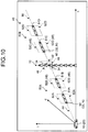
- the deletion unit 20H deletes part of nodes N1 arranged in at least one of the space before interference 50A and the space after interference 50B among the nodes N1 arranged in the first region 44 by the first arrangement unit 20E.
- FIG. 10 is an explanatory diagram of deletion of the node N1.
- the deletion unit 20H deletes the node N1 arranged in a space other than at least one of the acceleration/deceleration start scheduled space 51A, the deviation start scheduled space 51B, the deviation end scheduled space 51C, and the acceleration/deceleration end scheduled space 51D among the nodes N1 arranged by the first arrangement unit 20E.
- FIG. 10 illustrates a form in which the deletion unit 20H deletes the nodes N1 arranged in a space other than the acceleration/deceleration start scheduled space 51A, the deviation start scheduled space 51B, the deviation end scheduled space 51C, and the acceleration/deceleration end scheduled space 51D among the nodes N1 arranged on the scheduled traveling route 30.
- a route 60 (details will be described later) to be searched for can be prevented from being a zigzag shape.
- the WP 32 is not necessarily deleted.
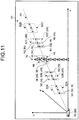
- the second arrangement unit 201 arranges the node N2 in the second region 46. That is, the second arrangement unit 201 arranges the node N2 in the second region 46 in the search space 40.
- FIG. 11 is an explanatory diagram of arrangement of the node N2.
- the second arrangement unit 201 arranges the node N2 in at least the second region 46.
- the second arrangement unit 201 arranges, in the second region 46, a plurality of nodes N2 different from each other in at least one of the position in the two-dimensional coordinate space (sd coordinate space) and the scheduled passing time (t) or the scheduled passing speed (v).
- the second arrangement unit 201 arranges the nodes N2 at a plurality of points including at least the local minimum point 34 included in the second region 46.
- the second arrangement unit 201 arranges the node N2 at the local minimum point 34 in the second region 46.
- the second arrangement unit 201 arranges the node N2 at a position obtained by shifting the local minimum point 34 toward a scheduled passing time axis (t-axis) direction to be distant from the scheduled traveling route 30.
- a shift amount thereof may be set in advance, or may be a random value.
- the second arrangement unit 20I preferably arranges the nodes N2 in the second region 46 with higher density than that of the nodes N1 arranged in the first region 44 on the scheduled traveling route 30.
- the information processing device 20 arranges the nodes N1 in the first region 44 not interfering with the object 12 on the scheduled traveling route 30, and for the interference region 42 interfering with the object 12, the information processing device 20 arranges the nodes N2 in the second region 46 around the interference region 42 with higher density than that of the nodes N1.
- the second arrangement unit 201 preferably arranges the node N2 in the third region 48 in addition to the second region 46.
- FIG. 11 illustrates a form in which the region 52B and the region 52C are determined to be the third regions 48.
- the second arrangement unit 201 arranges the nodes N2 in the region 52B and the region 52C as the third regions 48.
- the second arrangement unit 201 arranges, in the third region 48, the nodes N2 different from each other in at least one of the position in the two-dimensional coordinate space (sd coordinate space) and the scheduled passing time (t) or the scheduled passing speed (v).
- the second arrangement unit 201 arranges the nodes N2 at positions obtained by shifting the WPs 32 included in the regions (the acceleration/deceleration start scheduled space 51A, the deviation start scheduled space 51B, the deviation end scheduled space 51C, and the acceleration/deceleration end scheduled space 51D) of the scheduled traveling route 30 corresponding to the third region 48 toward the scheduled passing time axis (t-axis) direction to be distant from the scheduled traveling route 30.
- the shift amount may be set in advance, or may be a random value.
- the second arrangement unit 201 preferably arranges the nodes N2 in the third region 48 with higher density than that of the nodes N1 arranged in the first region 44 on the scheduled traveling route 30.
- the information processing device 20 selectively adds the nodes N2 to be arranged with high density not in the entire region around the scheduled traveling route 30 but in a specific region.
- All of the regions 52A, 52B, 52C, and 52D may be determined to be the third regions 48 in some cases.
- the second arrangement unit 201 may arrange a plurality of nodes N2 in each of the region 52A, the region 52B, the region 52C, and the region 52D.
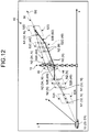
- the search unit 20J searches for a route.
- FIG. 12 is an explanatory diagram of search of the route 60.
- the search unit 20J searches for the route 60 going through a plurality of nodes N (the node N1, the node N2) and having a moving cost from a first point D1 to a second point D2 equal to or smaller than a threshold.
- the first point D1 is a specific point. Specifically, the first point D1 is a departure point or a present position of the mobile object 10.
- the first point D1 may be a specific point on the scheduled traveling route 30, or a point deviating from the scheduled traveling route 30.
- the center in the vehicle width direction of the mobile object 10 may be shifted from the center of the traveling possible region E. In such a case, the first point D1 is a position shifted in the vehicle width direction from the scheduled traveling route 30.
- the second point D2 is a point different from the first point D1 on the scheduled traveling route 30.
- the second point D2 is a point on a downstream side of the traveling direction with respect to the first point D1 on the scheduled traveling route 30.
- the second point D2 is a destination on the scheduled traveling route 30.
- the second arrangement unit 201 may further arrange the node N2 in a region around the second point D2.
- the second arrangement unit 201 may arrange a plurality of nodes N2 in a region around the second point D2 in the search space 40.
- the second arrangement unit 201 arranges the nodes N2 at positions obtained by shifting the second point D2 toward the scheduled passing time axis (t-axis) direction to be distant from the scheduled traveling route 30.
- the second arrangement unit 201 preferably arranges the nodes N2 in the region around the second point D2 with higher density than that of the nodes N1 arranged in the first region 44 on the scheduled traveling route 30.
- the moving cost is represented by time and energy required for movement between two points, that is, the first point D1 and the second point D2.
- the moving cost is, for example, a value corresponding to a distance in a straight line between the two points, a sum of a plurality of distances in a straight line between the two points, and the like.
- the moving cost may be a value obtained by weighting the distance in accordance with a movement environment along the scheduled traveling route 30.
- the search unit 20J generates a plurality of routes 60 from the first point D1 toward the second point D2 by connecting a plurality of nodes N (the node N1, the node N2) in a mesh-like manner from the first point D1 toward the second point D2.
- the search unit 20J generates a plurality of routes 60 connecting the first point D1, at least one node N included in the acceleration/deceleration start scheduled space 51A and the region 52A, at least one node N included in the deviation start scheduled space 51B and the region 52B, at least one node N included in the second region 46, at least one node N included in the deviation end scheduled space 51C and the region 52C, at least one node N included in the acceleration/deceleration end scheduled space 51D and the region 52D, and the second point D2.
- the search unit 20J searches for the route 60 having the moving cost that is equal to or smaller than the threshold from among the generated routes 60.
- FIG. 12 illustrates a route 60A having the lowest moving cost, and a route 60B having the next lowest moving cost.
- the moving cost may be calculated using a known method.
- the search unit 20J may calculate the moving cost of each of the routes 60 using a Dijkstra method.
- the search unit 20J preferably calculates the moving cost using the following Expression (1).
- C e t w ⁇ C ⁇ t + w ⁇ C ⁇ t + w ⁇ C ⁇ t , w ⁇ C ⁇ t
- Ce(t) represents the moving cost of an edge connecting adjacent nodes N in the route 60. That is, the search unit 20J calculates the sum total of the moving cost calculated for each edge included in the route 60 as the moving cost of the route 60.
- C ⁇ (t) represents a jerk degree of the edge.
- the jerk degree is a rate of change in acceleration per unit time, and represented by a vector quantity.
- C ⁇ (t) represents a yaw angle jerk degree of the edge.
- C ⁇ (t) represents a normalized distance of the edge, and is represented by the following Expression (2).
- W ⁇ , W ⁇ , and W ⁇ are weighting values, which are determined in advance.
- C ⁇ t ⁇ km ⁇ ⁇ min ⁇ max ⁇ ⁇ min
- ⁇ km represents a deviation between ⁇ km and V km , and is represented by the following Expression (3).
- ⁇ min represents the smallest ⁇ km
- ⁇ max represents the largest ⁇ km .
- k represents a serial number of an N1 group and an N3 group
- m represents a serial number of an N2 group arranged from Nl(k) or N3(k).
- ⁇ k represents N1 and N3.
- V km represents N2.
- the N1 group represents a group of the nodes N1.
- the N2 group represents a group of the nodes N2 arranged in the second region 46 among a plurality of nodes N2.
- the N3 group represents a group of the nodes N2 arranged in the third region 48 among a plurality of nodes N2.
- N2 represents the node N2 arranged in the second region 46 among a plurality of nodes N2.
- N3 represents the node N2 arranged in the third region 48 among a plurality of nodes N2.
- ⁇ km V km_s ⁇ ⁇ k_s 2 + V km_d ⁇ ⁇ k_d 2 + V km_t ⁇ ⁇ k_t + t ⁇ 2
- V km_s represents a value of an s-axis component of V km .
- ⁇ k_s represents N1 and N3.
- V km_d represents a value of a d-axis component of V km .
- V km_t represents a value of a t-axis component of V km .
- t ⁇ represents an offset amount of ⁇ k_t , and is represented by the following Expression (4).
- V (k_1)m represents the node (N2) at a distal end of a searched graph.
- ⁇ (k-1) represents the node N1 and the node N3 as a source of sampling of V (k-1)m .
- t is the same as that in the above Expression (3), and represents a value of the t-axis component.
- t ⁇ is set to prevent, when V (k-1)m deviates from ⁇ (k-1) , rapid acceleration/deceleration caused when V km approaches ⁇ k , and to cause V km the speed of which is close to that of the WP 32 to be easily selected.
- the search unit 20J can calculate the moving cost with higher accuracy for each of searched routes 60.
- the search unit 20J generates a plurality of routes 60 from the first point D1 toward the second point D2 by connecting a plurality of nodes N (the node N1, the node N2) in a mesh-like manner from the first point D1 toward the second point D2.
- the search unit 20J then calculates the moving cost of each of the routes 60 as described above.
- the search unit 20J searches for one or a plurality of routes 60 having the moving cost that is equal to or smaller than the threshold from among a plurality of routes 60.
- the threshold may be determined in advance.
- the search unit 20J may search for a predetermined number of routes 60 in ascending order of the moving cost from the lowest moving cost, from among a plurality of routes 60.
- the search unit 20J may search for one route 60 having the lowest moving cost from among a plurality of routes 60.
- the generation unit 20K generates a curved route using the route 60 searched for by the search unit 20J.
- FIG. 13 is an explanatory diagram of an example of a curved route 62.
- the curved route 62 is a route representing the route 60 with a curved line on which the mobile object 10 can travel.
- the generation unit 20K may generate the curved route 62 from the route 60 using a known method.
- the search unit 20J may search for a plurality of routes 60 having low moving cost in some cases.
- the generation unit 20K generates the curved route 62 for each of the searched routes 60.
- the generation unit 20K then specifies one curved route 62 having the moving cost that is the lowest from among a plurality of curved routes 62.
- the generation unit 20K may calculate the cost of the curved route 62 using a known method.
- the output control unit 20L outputs output information indicating the curved route 62 generated by the generation unit 20K.
- the output information may include information indicating the route 60 having the lowest moving cost searched for by the search unit 20J.
- the output information may be information including the route 60 in place of the curved route 62.
- the output control unit 20L outputs the output information indicating the curved route 62 to the power control unit 10G that controls the power unit 10H of the mobile object 10.
- the output control unit 20L outputs the curved route 62 to at least one of the power control unit 10G and the output unit 10A.
- the output control unit 20L outputs the curved route 62 to the output unit 10A.
- the output control unit 20L displays the output information including the curved route 62 on the display 10E.
- the output control unit 20L may control the speaker 10F to output a sound indicating the curved route 62.
- the output control unit 20L may output the output information indicating the curved route 62 to an external device via the communication unit 10D.
- the output control unit 20L may store the output information in the storage unit 20B.
- the output control unit 20L outputs the output information indicating the curved route 62 to the power control unit 10G.
- the power control unit 10G controls the power unit 10H in accordance with the curved route 62 received from the output control unit 20L.
- the power control unit 10G generates a power control signal for controlling the power unit 10H using the curved route 62, and controls the power unit 10H.
- the power control signal is a control signal for controlling a driving unit that performs driving related to traveling of the mobile object 10 in the power unit 10H.
- the power control signal includes a control signal for adjusting a steering angle, an accelerator quantity, and the like.
- the power control unit 10G acquires a present position, a posture, and speed of the mobile object 10 from the sensor 10B.
- the power control unit 10G uses these pieces of information acquired from the sensor 10B and the curved route 62 to generate the power control signal so that a deviation between the curved route 62 and the present position of the mobile object 10 becomes zero, and outputs the power control signal to the power unit 10H.
- the power control unit 10G controls the power unit 10H (steering of the mobile object 10, an engine, and the like) to perform traveling along the curved route.
- the mobile object 10 travels along the route corresponding to the curved route 62.
- At least part of processing for generating the power control signal from the curved route 62 may be performed by the output control unit 20L.
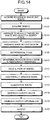
- FIG. 14 is a flowchart illustrating an example of the information processing procedure executed by the processing unit 20A.
- the acquisition unit 20C acquires the scheduled traveling route 30 (Step S100).
- the acquisition unit 20C acquires the object 12 (Step S102).
- the space constituting unit 20D then arranges the scheduled traveling route 30 and the object 12 in the search space 40 (Step S104).
- the first arrangement unit 20E arranges the node N1 in the first region 44 of the scheduled traveling route 30 (Step S106).
- the setting unit 20F sets the potential field 43 in the search space 40 (Step S108).
- the determination unit 20G determines a region in which the node N2 is additionally arranged (Step S110). For example, the determination unit 20G determines the second region 46 and the third region 48 to be regions in which the node N2 is additionally arranged.
- the deletion unit 20H deletes part of the nodes N1 arranged in at least one of the space before interference 50A and the space after interference 50B from among the nodes N1 arranged in the first region 44 at Step S106 (Step S112).
- the second arrangement unit 20I arranges the node N2 in the region determined at Step S110 (for example, the second region 46 and the third region 48) (Step S114).
- the search unit 20J searches for the route 60 having the traveling cost that is equal to or smaller than the threshold using the nodes N (the node N1, the node N2) arranged through the processing from Step S100 to Step S114 (Step S116).
- the generation unit 20K generates the curved route 62 by using the route 60 searched for at Step S116 (Step S118).
- Step S120 the generation unit 20K generates output information indicating the curved route 62 generated at Step S118 (Step S120), and outputs the output information (Step S122). This routine is then ended.
- the information processing device 20 includes the first arrangement unit 20E, the second arrangement unit 201, and the search unit 20J.
- the first arrangement unit 20E arranges the node N1 in the first region 44 not interfering with the object 12 on the scheduled traveling route 30.
- the second arrangement unit 20I arranges the node N2 in the second region 46 around the interference region 42 interfering with the object 12.
- the search unit 20J searches for the route 60 going through a plurality of nodes N (the node N1, the node N2) and having the moving cost from the first point D1 to the second point D2 on the scheduled traveling route 30 equal to or smaller than the threshold.
- the information processing device 20 arranges the node N1 in the first region 44 not interfering with the object 12 on the scheduled traveling route 30, and for the interference region 42 interfering with the object 12, the information processing device 20 arranges the node N2 in the second region 46 around the interference region 42.
- the information processing device 20 does not randomly arrange the nodes N in the entire region along the scheduled traveling route 30, but selectively arranges the nodes N in a specific region to be used for searching for the route 60.
- the information processing device 20 can search for a quasi-optimal route 60.
- processing time and a processing load can be reduced in addition to the effect described above as compared with a conventional system of randomly arranging the nodes N in the entire region.
- FIG. 15 is an example of a hardware configuration diagram of the information processing device 20 according to the arrangement described above.
- the information processing device 20 includes a control device such as a central processing unit (CPU) 86, a storage device such as a read only memory (ROM) 88, a random access memory (RAM) 90, and a hard disk drive (HDD) 92, an I/F unit 82 serving as an interface with various appliances, an output unit 80 that outputs various pieces of information such as output information, an input unit 94 that receives an operation performed by a user, and a bus 96 for connecting the components, and has a hardware configuration utilizing a typical computer.
- a control device such as a central processing unit (CPU) 86, a storage device such as a read only memory (ROM) 88, a random access memory (RAM) 90, and a hard disk drive (HDD) 92
- I/F unit 82 serving as an interface with various appliances
- an output unit 80 that outputs various pieces of information such as output information
- an input unit 94 that receives an operation performed by a user
- a bus 96 for connecting the components
- the computer program for executing the pieces of processing described above performed by the information processing device 20 according to the arrangement described above may be stored in the HDD 92.
- the computer program for executing the pieces of processing described above performed by the information processing device 20 according to the arrangement described above may be embedded and provided in the ROM 88.
- the computer program for executing the processing described above performed by the information processing device 20 according to the arrangement described above may be stored on a computer-readable storage medium such as a compact disc read only memory (CD-ROM), a compact disc recordable (CD-R), a memory card, a digital versatile disc (DVD), and a flexible disk (FD), as an installable or executable file to be provided as a computer program product.
- the computer program for executing the processing described above performed by the information processing device 20 according to the arrangement described above may be stored in a computer connected to a network such as the Internet and provided by being downloaded via the network.
- the computer program for executing the processing described above performed by the information processing device 20 according to the arrangement described above may be provided or distributed via a network such as the Internet.
Landscapes
- Engineering & Computer Science (AREA)
- Radar, Positioning & Navigation (AREA)
- Remote Sensing (AREA)
- Physics & Mathematics (AREA)
- General Physics & Mathematics (AREA)
- Business, Economics & Management (AREA)
- Human Resources & Organizations (AREA)
- Automation & Control Theory (AREA)
- Strategic Management (AREA)
- Economics (AREA)
- Game Theory and Decision Science (AREA)
- Development Economics (AREA)
- Entrepreneurship & Innovation (AREA)
- Marketing (AREA)
- Operations Research (AREA)
- Quality & Reliability (AREA)
- Tourism & Hospitality (AREA)
- General Business, Economics & Management (AREA)
- Theoretical Computer Science (AREA)
- Traffic Control Systems (AREA)
- Control Of Driving Devices And Active Controlling Of Vehicle (AREA)
- Navigation (AREA)
Abstract
Description
- The present disclosure relates to an information processing device, a mobile object, an information processing method, and a computer-readable medium.
- An automatic driving technique for automatically steering an automobile has been attracting attention. For example, disclosed is a technique for generating a route for avoiding collision with an object such as an obstacle. There is also disclosed a technique for randomly arranging nodes in a traveling region and searching for a route having lower traveling cost among a plurality of routes sequentially going through a plurality of nodes from a present location to a destination.
- However, in the known device, a random sampling region for searching for the route becomes a wide range, and a route having poor quasi-optimality may be searched for.
-
-
FIG. 1 is a diagram illustrating an example of a mobile object; -
FIG. 2 is a block diagram illustrating an example of the mobile object; -
FIG. 3 is a schematic diagram illustrating an example of a scheduled traveling route; -
FIG. 4 is a schematic diagram illustrating a search space; -
FIGS. 5A and 5B are explanatory diagrams of the search space; -
FIGS. 6A and 6B are explanatory diagrams of arrangement of an object in the search space; -
FIGS. 7A to 7D are explanatory diagrams of an example of a potential field; -
FIGS. 8A and 8B are schematic diagrams of arrangement of a local minimum point in the search space; -
FIG. 9 is an explanatory diagram of a region to which a node is added; -
FIG. 10 is an explanatory diagram of deletion of the node; -
FIG. 11 is an explanatory diagram of arrangement of the node; -
FIG. 12 is an explanatory diagram of search of a route; -
FIG. 13 is an explanatory diagram of a curved route; -
FIG. 14 is a flowchart illustrating an example of an information processing procedure; and -
FIG. 15 is a hardware configuration diagram. - According to an arrangement, an information processing device includes a first arrangement unit, a second arrangement unit, and a search unit. The first arrangement unit is configured to arrange a node in a first region not interfering with an object on a scheduled traveling route. The second arrangement unit is configured to arrange a node in a second region around an interference region interfering with the object. The search unit is configured to search for a route going through a plurality of nodes and having a moving cost from a first point to a second point on the scheduled traveling route equal to or smaller than a threshold.
- The following describes an information processing device, a mobile object, an information processing method, and a computer-readable medium in detail with reference to the attached drawings.
-
FIG. 1 is a diagram illustrating an example of amobile object 10 according to an arrangement. - The
mobile object 10 includes aninformation processing device 20, anoutput unit 10A, asensor 10B, aninput device 10C, apower control unit 10G, and apower unit 10H. - The
information processing device 20 searches for a route of the mobile object 10 (details will be described later). Theinformation processing device 20 is, for example, a special-purpose or a general-purpose computer. In the present arrangement, described is a case in which theinformation processing device 20 is mounted on themobile object 10 as an example. - The
mobile object 10 is a movable object. Themobile object 10 is, for example, a vehicle (a motorcycle, an automobile, and a bicycle), a dolly, a robot, a ship, and a flying object (an airplane, an unmanned aerial vehicle (UAV), and the like). Themobile object 10 is, for example, a mobile object that travels through a driving operation performed by a person, or a mobile object that can automatically travel (autonomously travel) without a driving operation performed by a person. The mobile object that can automatically travel is, for example, an automatic driving vehicle. Themobile object 10 according to the present arrangement is described as a vehicle that can autonomously travel as an example. - The
information processing device 20 is not necessarily mounted on themobile object 10. Theinformation processing device 20 may be mounted on a stationary object. The stationary object is an unmovable object or an object stabilized on the ground. The stationary object is, for example, a guardrail, a pole, a parked vehicle, and a road sign. Theinformation processing device 20 may be mounted on a cloud server that executes processing on a cloud. - The
output unit 10A outputs various pieces of information. In the present arrangement, theoutput unit 10A outputs output information. - The
output unit 10A has, for example, a communication function for transmitting the output information, a display function for displaying the output information, and a sound outputting function for outputting a sound indicating the output information. For example, theoutput unit 10A includes acommunication unit 10D, adisplay 10E, and aspeaker 10F. - The
communication unit 10D communicates with an external device. Thecommunication unit 10D is a VICS (registered trademark) communication circuit or a dynamic map communication circuit. Thecommunication unit 10D transmits the output information to the external device. Thecommunication unit 10D receives road information and the like from the external device. The road information includes a traffic light, a sign, surrounding buildings, a width of each lane, a center line of a lane, and the like. The road information may be stored in a storage unit 20B. - The
display 10E displays the output information. Thedisplay 10E is, for example, a known liquid crystal display (LCD), a projection device, and a light. Thespeaker 10F outputs a sound indicating the output information. - The
sensor 10B is a sensor that acquires a traveling environment of themobile object 10. The traveling environment is, for example, observation information of themobile object 10 and peripheral information of themobile object 10. Thesensor 10B is, for example, an outer field sensor or an inner field sensor. - The inner field sensor is a sensor that observes the observation information. The observation information is information including at least acceleration of the
mobile object 10. Specifically, the observation information includes at least one of the acceleration of themobile object 10, speed of themobile object 10, and angular speed of themobile object 10. - The inner field sensor is, for example, an inertial measurement unit (IMU), an acceleration sensor, a speed sensor, and a rotary encoder. The IMU observes the observation information including triaxial acceleration and triaxial angular speed of the
mobile object 10. - The outer field sensor observes the peripheral information of the
mobile object 10. The outer field sensor may be mounted on themobile object 10, or may be mounted outside the mobile object 10 (for example, another mobile object or an external device). - The peripheral information is information indicating a condition of surroundings of the
mobile object 10. The surroundings of themobile object 10 are a region within a predetermined range around themobile object 10. This range is a range that can be observed by the outer field sensor. The range may be set in advance. - For example, the peripheral information is at least one of a photographed image of the surroundings of the
mobile object 10 and distance information. The peripheral information may include location information of themobile object 10. The photographed image is photographed image data obtained by photography (hereinafter, simply referred to as a photographed image in some cases). The distance information is information indicating a distance from themobile object 10 to an object. The object is a point that can be observed by the outer field sensor in an outer field. The location information may be a relative position or an absolute position. - The outer field sensor is, for example, a photographing device that obtains the photographed image by photography, a distance sensor (a millimetric wave radar, a laser sensor, and a distance image sensor), and a position sensor (Global Navigation Satellite System (GNSS), a Global Positioning System (GPS), and a wireless communication device).
- The photographed image is, for example, digital image data in which a pixel value is defined for each pixel, and a depth map in which a distance from the
sensor 10B is defined for each pixel. The laser sensor is, for example, a two-dimensional Laser Imaging Detection and Ranging (LIDAR) sensor arranged in parallel with a horizontal plane, and a three-dimensional LIDAR sensor. - The
input device 10C receives various instructions and an input of information from a user. Theinput device 10C is, for example, a pointing device such as a mouse and a trackball, or an input device such as a keyboard. Theinput device 10C may be an input function of a touch panel that is arranged integrally with thedisplay 10E. - The
power control unit 10G controls thepower unit 10H. Thepower unit 10H is a device that is for driving and mounted on themobile object 10. Thepower unit 10H is, for example, an engine, a motor, and a wheel. - The
power unit 10H is driven by being controlled by thepower control unit 10G. For example, thepower control unit 10G determines a condition of the surroundings on the basis of the output information generated by theinformation processing device 20, information obtained from thesensor 10B, and the like, and controls an accelerator quantity, a brake quantity, a steering angle, and the like. For example, thepower control unit 10G controls thepower unit 10H of themobile object 10 so that themobile object 10 moves along a route generated by theinformation processing device 20. - Next, the following describes an electrical configuration of the
mobile object 10 in detail.FIG. 2 is a block diagram illustrating an example of the configuration of themobile object 10. - The
mobile object 10 includes theinformation processing device 20, theoutput unit 10A, thesensor 10B, theinput device 10C, thepower control unit 10G, and thepower unit 10H. As described above, theoutput unit 10A includes thecommunication unit 10D, thedisplay 10E, and thespeaker 10F. - The
information processing device 20, theoutput unit 10A, thesensor 10B, theinput device 10C, and thepower control unit 10G are connected to each other via abus 10J. Thepower unit 10H is connected to thepower control unit 10G. - The
information processing device 20 includes the storage unit 20B and a processing unit 20A. That is, theoutput unit 10A, thesensor 10B, theinput device 10C, thepower control unit 10G, and the storage unit 20B are connected to the processing unit 20A via thebus 10J. - At least one of the storage unit 20B, the
output unit 10A (thecommunication unit 10D, thedisplay 10E, and thespeaker 10F), thesensor 10B, theinput device 10C, and thepower control unit 10G may be connected to the processing unit 20A in a wired or wireless manner. At least one of the storage unit 20B, theoutput unit 10A (thecommunication unit 10D, thedisplay 10E, and thespeaker 10F), thesensor 10B, theinput device 10C, and thepower control unit 10G may be connected to the processing unit 20A via a network. - The storage unit 20B stores various pieces of data. The storage unit 20B may be, for example, a semiconductor memory element such as a random access memory (RAM) and a flash memory, a hard disk, and an optical disc. The storage unit 20B may be arranged outside the
information processing device 20. The storage unit 20B may also be arranged outside themobile object 10. For example, the storage unit 20B may be arranged in a server device installed on a cloud. - The storage unit 20B may be a storage medium. Specifically, the storage medium may be a storage medium that downloads a computer program or various pieces of information via a local area network (LAN) or the Internet to be stored or temporarily stored. The storage unit 20B may include a plurality of storage media.
- The processing unit 20A includes an acquisition unit 20C, a
space constituting unit 20D, afirst arrangement unit 20E, asetting unit 20F, adetermination unit 20G, adeletion unit 20H, asecond arrangement unit 201, asearch unit 20J, ageneration unit 20K, and anoutput control unit 20L. - Each processing function of the processing unit 20A is stored in the storage unit 20B as a computer program that can be executed by a computer. The processing unit 20A is a processor that implements a functional unit corresponding to each computer program by reading out the computer program from the storage unit 20B to be executed.
- The processing unit 20A that has read out each computer program is assumed to have each functional unit illustrated in the processing unit 20A of
FIG. 2 . With reference toFIG. 2 , described is a case in which the acquisition unit 20C, thespace constituting unit 20D, thefirst arrangement unit 20E, thesetting unit 20F, thedetermination unit 20G, thedeletion unit 20H, the second arrangement unit 20I, thesearch unit 20J, thegeneration unit 20K, and theoutput control unit 20L are implemented by the single processing unit 20A. - The processing unit 20A may be configured by combining a plurality of independent processors for implementing each of functions. In this case, each function is implemented when each processor executes the computer program. There may be a case in which each processing function is configured as a computer program and one processing circuit executes each computer program, and a case in which a specific function is mounted in a dedicated and independent program execution circuit.
- A term "processor" used in the arrangement represents, for example, a circuit of a central processing unit (CPU), a graphical processing unit (GPU), an application specific integrated circuit (ASIC), or a programmable logic device (for example, a simple programmable logic device (SPLD), a complex programmable logic device (CPLD), and a field programmable gate array (FPGA)).
- The processor implements a function by reading out and executing the computer program stored in the storage unit 20B. Instead of storing the computer program in the storage unit 20B, the computer program may be directly embedded in a circuit of the processor. In this case, the processor implements the function by reading out and executing the computer program embedded in the circuit.
- The acquisition unit 20C acquires a scheduled traveling route. The scheduled traveling route is a route over which the
mobile object 10 is scheduled to pass when moving from a certain point to another point. For example, the scheduled traveling route is a route over which themobile object 10 is scheduled to pass when moving from a present location to a destination. - Specifically, the scheduled traveling route is constituted of a line passing over a road over which the
mobile object 10 passes when moving from a certain point (for example, the present location of the mobile object 10) to another point (for example, the destination), and a line connecting between lines passing over different roads. The line passing over the road is, for example, a line passing through the center of the road to be passed (the center of a lane along a traveling direction). The line connecting between lines passing over different roads is, for example, a line that connects an end of a line passing over one of the roads and an end of a line passing over the other one of the roads such that a curvature draws a certain arc. - The scheduled traveling route may further include identification information of the road to be passed (hereinafter, referred to as a road ID in some cases) and speed information indicating recommended speed of the
mobile object 10. -
FIG. 3 is a schematic diagram illustrating an example of the scheduled travelingroute 30. The scheduled travelingroute 30 is represented by a line passing through the center of a traveling possible region E of a road R. The traveling possible region E is a region in which themobile object 10 can travel. The traveling possible region E is, for example, a region along the lane on which themobile object 10 travels. - In the present arrangement, described is a case in which the scheduled traveling
route 30 is represented by a group of a plurality of reference points 32 (hereinafter, referred to as a way point (WP) 32). TheWP 32 is a point defining a position and at least one of scheduled passing time and scheduled passing speed of themobile object 10. TheWP 32 may be represented by a vector in place of the point. - The position defined by the
WP 32 indicates a position on a map. The position is, for example, represented by world coordinates. The position may be represented as a relative position with respect to the present position of themobile object 10. - The scheduled passing time defined by the
WP 32 represents time at which themobile object 10 is scheduled to pass through the position of theWP 32. The scheduled passing time may be relative time with respect to specific time, or time corresponding to a standard time and frequency signal. - The scheduled passing speed defined by the
WP 32 represents scheduled speed at the time when themobile object 10 passes through the position of theWP 32. The scheduled passing speed may be relative speed with respect to specific speed, or may be absolute speed. - Returning to
FIG. 2 , the description will be continued. Thespace constituting unit 20D arranges the scheduled travelingroute 30 and the object in a search space. -
FIG. 4 is a schematic diagram illustrating asearch space 40. Thesearch space 40 is a space represented by a two-dimensional coordinate space (sd coordinate space), and a scheduled passing time axis (t) or a scheduled passing speed axis (v) orthogonal to the two-dimensional coordinate space.FIG. 4 illustrates the scheduled passing time axis (t) as an example of the coordinate axis orthogonal to the two-dimensional coordinate space. - The two-dimensional coordinate space is a space of a two-dimensional plane along the traveling possible region E (refer to
FIG. 3 ) of themobile object 10 moving on the scheduled travelingroute 30. The two-dimensional coordinate space is defined with an s-axis along a direction following the road of themobile object 10 and a d-axis along a vehicle width direction of themobile object 10. The s-axis and the d-axis are arranged to be orthogonal to each other. The s-axis is identical to an extending direction of the scheduled travelingroute 30. The vehicle width direction is a direction orthogonal to the traveling direction of themobile object 10. - The scheduled passing time axis (t) orthogonal to the two-dimensional coordinate space (sd coordinate space) is a coordinate axis indicating the scheduled passing time of the
mobile object 10. - As described above, the
search space 40 may be represented by using the scheduled passing speed axis (v) as a coordinate axis in place of the scheduled passing time axis (t) . - The
space constituting unit 20D may generate thesearch space 40 in accordance with content defined by theWP 32 constituting the scheduled travelingroute 30. - For example, the
WP 32 constituting the scheduled travelingroute 30 is assumed to define the position and the scheduled passing time. In this case, thespace constituting unit 20D may generate thesearch space 40 using the two-dimensional coordinate space (sd coordinate space) and the scheduled passing time axis (t) as coordinate axes. For example, theWP 32 constituting the scheduled travelingroute 30 is assumed to define the position and the scheduled passing speed. In this case, thespace constituting unit 20D may generate thesearch space 40 using the two-dimensional coordinate space (sd coordinate space) and the scheduled passing speed axis (v) as the coordinate axes. - Next, the
space constituting unit 20D arranges the scheduled travelingroute 30 in thesearch space 40. For example, thespace constituting unit 20D arranges eachWP 32 at the position indicated by theWP 32 constituting the scheduled travelingroute 30, that is, a point corresponding to the scheduled travelingroute 30. The position defined by theWP 32 may be represented by world coordinates in some cases. In this case, thespace constituting unit 20D may convert the position coordinates represented by world coordinates and defined by theWP 32 into position coordinates represented by the sd coordinate space, and may arrange the position coordinates in thesearch space 40. - The
space constituting unit 20D may represent thesearch space 40 using an xy coordinate space or an xyz coordinate space of world coordinates in place of the sd coordinate space. In this case, the xy coordinate space is a two-dimensional plane orthogonal to a Z-axis direction indicating a vertical direction (height). -
FIGS. 5A and 5B are explanatory diagrams representing the two-dimensional coordinate space of thesearch space 40 using each of the xy coordinate space and the sd coordinate space respectively.FIG. 5A is an example of representing the two-dimensional coordinate space of thesearch space 40 with the xy coordinate space, and arranging the scheduled travelingroute 30 therein.FIG. 5B is an example of representing the two-dimensional coordinate space of thesearch space 40 with the sd coordinate space, and arranging the scheduled travelingroute 30 therein. - Returning to
FIG. 2 , the description will be continued. Thespace constituting unit 20D further arranges an object in thesearch space 40. -
FIGS. 6A and 6B are explanatory diagrams of arrangement of anobject 12 in thesearch space 40.FIG. 6A is an example of representing thesearch space 40 with the two-dimensional coordinate space (sd coordinate space).FIG. 6B is an example of representing thesearch space 40 with a three-dimensional space (sdt coordinate space). - The
object 12 is a thing that possibly obstructs traveling of themobile object 10. Theobject 12 is, for example, an obstacle. The obstacle is another mobile object, a living thing such as a person and a tree, a non-living thing arranged on the ground (for example, various objects such as a sign, a traffic light, and a guardrail), and the like. Theobject 12 is not limited to the obstacle. For example, theobject 12 may be a non-obstacle. The non-obstacle is a region in which a road surface is deteriorated in the traveling possible region E. The region in which a road surface is deteriorated is, for example, a puddle and a depressed region. The non-obstacle may be a traveling-prohibited region. The traveling-prohibited region is a region in which traveling is prohibited represented by a rule of the road. The traveling-prohibited region is, for example, a region defined by a sign of no passing. - For example, the
space constituting unit 20D acquires information for specifying theobject 12 from the acquisition unit 20C. In the present arrangement, thespace constituting unit 20D acquires information indicating a position, a size, and a shape of theobject 12 in a real space. Thespace constituting unit 20D may acquire information indicating the position of theobject 12 in the real space and a region occupied by theobject 12 in the real space. - For example, the
space constituting unit 20D acquires information indicating the position, the size, and the shape of theobject 12 from thesensor 10B via the acquisition unit 20C. In this case, the acquisition unit 20C derives the information indicating the position, the size, and the shape of theobject 12 using a known method with a sensing result obtained by thesensor 10B. Thespace constituting unit 20D may derive the information indicating the position, the size, and the shape of theobject 12 from the acquisition unit 20C. - The
space constituting unit 20D then arranges theobject 12 in the search space 40 (refer toFIGS. 6A and 6B ). - Returning to
FIG. 2 , the description will be continued. Next, the following describes thefirst arrangement unit 20E. Thefirst arrangement unit 20E arranges a node. The node is a point used for searching for a route (to be described later). Theinformation processing device 20 searches for the route by searching for a plurality of routes connecting a plurality of nodes toward a traveling direction (details will be described later). - The following description uses
FIGS. 6A and 6B . - In the present arrangement, the
first arrangement unit 20E arranges a node N in afirst region 44 of the scheduled travelingroute 30. That is, thefirst arrangement unit 20E arranges the node N in thefirst region 44 of thesearch space 40. - The
first region 44 is a region not interfering with theobject 12 on the scheduled travelingroute 30. In other words, thefirst region 44 is a region other than aninterference region 42 interfering with theobject 12 on the scheduled travelingroute 30. - Interfering with the
object 12 means that, when themobile object 10 is assumed to travel along the scheduled travelingroute 30, themobile object 10 is brought into contact with theobject 12 or travels over theobject 12. - For example, the
space constituting unit 20D sets, as the node N, theWP 32 arranged in thefirst region 44 as a region other than theinterference region 42 among a plurality ofWPs 32 constituting the scheduled travelingroute 30. Due to this, among theWPs 32 constituting the scheduled travelingroute 30, theWP 32 arranged in thefirst region 44 other than theinterference region 42 is set as the node N. In the following description, the node N arranged by thefirst arrangement unit 20E is referred to as a node N1. - Returning to
FIG. 2 , the description will be continued. Next, the following describes thesetting unit 20F. Thesetting unit 20F sets a potential field in thesearch space 40. -
FIGS. 7A to 7D are explanatory diagrams of an example of a potential field 43. InFIGS. 7A to 7D , the two-dimensional coordinate space (sd coordinate space) of thesearch space 40 is illustrated, and a p-axis indicating the potential field 43 is illustrated as a coordinate axis orthogonal to the two-dimensional coordinate space. - The potential field 43 defines a potential value of each point in the
search space 40. The potential value represents a risk of traveling. That is, thesetting unit 20F sets a higher potential value to a point where the risk of traveling is higher, and sets a lower potential value to a point where the risk of traveling is lower. - In the present arrangement, the
setting unit 20F sets the potential field indicating a lower potential value as being closer to the scheduled travelingroute 30 or more distant from theobject 12. - In particular, the
setting unit 20F forms a potential line L constituted of a group of potential values in thesearch space 40. Specifically, thesetting unit 20F defines a high potential value in a region occupied by theobject 12 in thesearch space 40. - For example, as illustrated in
FIG. 7A , thesetting unit 20F sets the potential line L indicating the potential value in thesearch space 40. - Specifically, the
setting unit 20F first defines the lowest potential value in thefirst region 44 not interfering with theobject 12 on the scheduled travelingroute 30 arranged in thesearch space 40. This is because the scheduled travelingroute 30 is a line passing through the center of the traveling possible region E of the road R, and because the region on the scheduled travelingroute 30 in which theobject 12 is not present hardly deviates from the traveling possible region E. - Next, the
setting unit 20F sets a potential value higher than that of the scheduled travelingroute 30 in the region occupied by theobject 12. For example, thesetting unit 20F forms a first line L1 indicating a higher potential value than that of the scheduled travelingroute 30 and extending in a d-axis direction in the region occupied by theobject 12. - The
setting unit 20F then forms a second line L2 the potential value of which lowers with a first gradient from both ends in the d-axis direction of the first line L1 toward the outside of theobject 12. - The
setting unit 20F forms a third line L3 the potential value of which increases with a third gradient from the scheduled travelingroute 30 toward both ends in the d-axis direction of the traveling possible region E (for example, road shoulders). - The gradient of the second line L2 is preferably larger than the gradient of the third line L3. This is because the
mobile object 10 is preferably prevented from taking a wide turn to avoid theobject 12 at the time of traveling. - The gradient of the second line L2 is an angle formed by a straight line parallel with the d-axis and the first line L1. The gradient of the third line L3 is an angle formed by the straight line parallel with the d-axis and the third line L3. The gradients of the second line L2 and the third line L3 may be set in advance by the user. Each of the gradients may be a value corresponding to a side distance between the
object 12 and themobile object 10 at the time when themobile object 10 travels and passes theobject 12. For example, thesetting unit 20F may set the gradients so that the gradients of the second line L2 and the third line L3 are reduced as the side distance increases. The side distance may be set in advance by the user. - At least one of the first line L1, the second line L2, and the third line L3 may be a straight line the gradient of which is fixed, or a curved line the gradient of which varies.
- The
setting unit 20F forms the potential line L by connecting the first line L1, the second line L2, and the third line L3 to each other from theWP 32 toward both ends in the d-axis direction of the traveling possible region E for eachWP 32 constituting the scheduled travelingroute 30. In a region not overlapping with theobject 12 on the scheduled travelingroute 30, the potential line L is formed by a pair of third lines L3 extending from theWP 32 toward both ends in the d-axis direction of the traveling possible region E. In this way, thesetting unit 20F sets the potential field 43 by forming the potential line L. - Next, the
setting unit 20F specifies a localminimum point 34 in thesearch space 40. The localminimum point 34 is a point indicating a local minimum peak of the potential value indicated by the potential field 43. -
FIGS. 7B to 7D illustrate a cross section obtained by cutting the potential field 43 of thesearch space 40 illustrated inFIG. 7A along a two-dimensional plane formed by the p-axis and the d-axis.FIG. 7B is an A-A' cross section ofFIG. 7A. FIG. 7C is a B-B' cross section ofFIG. 7A. FIG. 7D is a C-C' cross section ofFIG. 7A . - As illustrated in
FIG. 7B , in the cross section (A-A' cross section) including thefirst region 44 not interfering with theobject 12 on the scheduled travelingroute 30, the position of theWP 32 is the localminimum point 34. - As illustrated in
FIGS. 7C and 7D , in theinterference region 42 interfering with theobject 12 on the scheduled travelingroute 30, each position shifted from theWP 32 toward both ends in the d-axis direction is the localminimum point 34. That is, on the potential line L interfering with theobject 12, a plurality of localminimum points 34 are present to avoid theobject 12. - The
setting unit 20F then arranges the localminimum point 34 in thesearch space 40.FIGS. 8A and 8B are schematic diagrams illustrating an example of a state in which the localminimum point 34 is arranged in thesearch space 40.FIG. 8A is an example of representing thesearch space 40 as the two-dimensional coordinate space (sd coordinate space).FIG. 8B is an example of representing thesearch space 40 as the three-dimensional space (sdt coordinate space). - As illustrated in
FIGS. 8A and 8B , the localminimum point 34 is arranged at a local minimum peak of the potential value of the risk of traveling in thesearch space 40. Thus, in theinterference region 42 interfering with theobject 12 on the scheduled travelingroute 30, the localminimum point 34 is arranged at a position avoiding theobject 12 and where the risk of traveling is low. - In the present arrangement, described is a case in which the
object 12 is an immovable object as an example.FIGS. 8A and 8B illustrate a case in which oneobject 12 is present on the scheduled travelingroute 30 as an example. Accordingly, the position of theobject 12 is fixed irrespective of scheduled passing time (t). When theobject 12 is a movable object, a position corresponding to the scheduled passing time (t) varies. In this case, thesetting unit 20F may generate the potential field 43 for each scheduled passing time (t), and set the localminimum point 34 at a position not interfering with the movingobject 12. - Returning to
FIG. 2 , the description will be continued. Thedetermination unit 20G determines a region to which the node N is added. That is, thedetermination unit 20G determines a region in which the node N is additionally arranged in addition to the node N1 arranged by thefirst arrangement unit 20E. In the following description, for convenience of explanation, the node N to be additionally arranged is referred to as a node N2. -
FIG. 9 is an explanatory diagram of an object a region to which the node N2 is added. Thedetermination unit 20G determines the localminimum point 34, asecond region 46, and athird region 48 to be regions to which the node N2 is additionally arranged. - In
FIG. 9 , thesecond region 46 and thethird region 48 are separately present. Alternatively, a deviation start scheduledspace 51B and a deviation end scheduledspace 51C (described later) may be taken to be long, and thesecond region 46 and thethird region 48 may be caused to be one large region. - The
second region 46 is a region around theinterference region 42 interfering with theobject 12. Thesecond region 46 is a region in thesearch space 40. Thesecond region 46 is a region deviating from the scheduled travelingroute 30, and is a region around theinterference region 42. More specifically, thesecond region 46 is a region deviating from the scheduled travelingroute 30, a region around theinterference region 42, and a peripheral region around the localminimum point 34. - Specifically, the
second region 46 is a region including the localminimum point 34. Thesecond region 46 is a space different from theobject 12 interfering with the scheduled travelingroute 30 in at least one of the position in the two-dimensional coordinate space (sd coordinate space) and the scheduled passing time (t) or the scheduled passing speed (v), in thesearch space 40. - The
search space 40 is assumed to define the scheduled passing time (t) as a coordinate axis orthogonal to the sd coordinate space. In this case, thedetermination unit 20G may determine a space including the localminimum point 34 and different from theobject 12 interfering with the scheduled travelingroute 30 in the position in the two-dimensional coordinate space (sd coordinate space) and the scheduled passing time (t) to be thesecond region 46. - The
search space 40 is assumed to define the scheduled passing speed (v) as a coordinate axis orthogonal to the sd coordinate space. In this case, thedetermination unit 20G may determine a space including the localminimum point 34 and different from theobject 12 interfering with the scheduled travelingroute 30 in the position in the two-dimensional coordinate space (sd coordinate space) and the scheduled passing speed (v) to be thesecond region 46. - The
third region 48 is a region deviating from the scheduled travelingroute 30 in at least one of a space beforeinterference 50A and a space afterinterference 50B, in thesearch space 40. - The space before
interference 50A is a space before the scheduled passing time (t) at which the scheduled travelingroute 30 interferes with theobject 12 or the scheduled passing speed (v) at the position where the scheduled travelingroute 30 interferes with theobject 12, in thesearch space 40. - The space after
interference 50B is a space after the scheduled passing time (t) at which the scheduled travelingroute 30 interferes with theobject 12 or the scheduled passing speed (v) at the position where the scheduled travelingroute 30 interferes with theobject 12, in thesearch space 40. - The region deviating from the scheduled traveling
route 30 indicates a region different from the scheduled travelingroute 30 in thesearch space 40 in at least one of the position in the two-dimensional coordinate space (sd coordinate space) and the scheduled passing time (t) or the scheduled passing speed (v). - In the present arrangement,
determination unit 20G determines a specific region in the space beforeinterference 50A to be thethird region 48. Thedetermination unit 20G determines a specific region in the space afterinterference 50B to be thethird region 48. - Specifically, the
determination unit 20G determines a region around at least one of an acceleration/deceleration start scheduledspace 51A and the deviation start scheduledspace 51B and deviating from the scheduled travelingroute 30 in the space beforeinterference 50A to be thethird region 48. - The acceleration/deceleration start scheduled
space 51A is a space in which themobile object 10 traveling on the scheduled travelingroute 30 starts acceleration/deceleration before interfering with theobject 12, on the scheduled travelingroute 30 in the space beforeinterference 50A. For example, the storage unit 20B stores, in advance, information for specifying theWP 32 at which acceleration/deceleration is to be started to avoid theobject 12. - The information for specifying the
WP 32 at which acceleration/deceleration is started may be stored, for example, in the storage unit 20B in advance through an operation of theinput device 10C performed by the user. The information for specifying theWP 32 at which acceleration/deceleration is started may be represented by a distance from theobject 12, for example. - For example, the storage unit 20B stores in advance a look-up table associating the speed of the
mobile object 10 with the information for specifying theWP 32 at which acceleration/deceleration is started. In place of the speed of themobile object 10, time required for avoiding theobject 12 until the avoidance is ended and an avoiding method (slowly avoiding, quickly avoiding) may be registered in the look-up table. Thedetermination unit 20G may acquire the information for specifying theWP 32 at which acceleration/deceleration is started by reading, from the look-up table, the information for specifying theWP 32 at which acceleration/deceleration is started corresponding to current speed per hour. Thedetermination unit 20G may acquire the information for specifying theWP 32 at which acceleration/deceleration is started by reading, from the look-up table, the information for specifying theWP 32 at which acceleration/deceleration is started corresponding to the required time or the avoiding method input by the user. - For example, an acceleration/
deceleration starting point 36A illustrated inFIG. 9 is assumed to be used as the information indicating theWP 32 at which acceleration/deceleration is started. In this case, thedetermination unit 20G specifies, as the acceleration/deceleration start scheduledspace 51A, the acceleration/deceleration starting point 36A on the scheduled travelingroute 30 and a predetermined number of (for example, two) WPs 32 adjacent to the acceleration/deceleration starting point 36A. Thedetermination unit 20G then determines aregion 52A around the acceleration/deceleration start scheduledspace 51A on the scheduled travelingroute 30 in the space beforeinterference 50A to be thethird region 48. - The
region 52A around the acceleration/deceleration start scheduledspace 51A is different from the acceleration/deceleration start scheduledspace 51A in thesearch space 40 in at least one of the position in the two-dimensional coordinate space (sd coordinate space) and the scheduled passing time (t) or the scheduled passing speed (v). - The deviation start scheduled
space 51B is a space in which themobile object 10 that has traveled on the scheduled travelingroute 30 starts to deviate from the scheduled travelingroute 30 to avoid theobject 12 on the scheduled travelingroute 30 in the space beforeinterference 50A. For example, the storage unit 20B stores, in advance, the information for specifying theWP 32 that starts to deviate from the scheduled travelingroute 30 to avoid theobject 12. The information may be, for example, stored in the storage unit 20B in advance through an operation of theinput device 10C by the user. The information may be represented by a distance from theobject 12, for example. - For example, the storage unit 20B stores, in advance, the look-up table associating the speed of the
mobile object 10 with the information for specifying theWP 32 at which deviation from the scheduled travelingroute 30 is started. In place of the speed of themobile object 10, the time required for avoiding theobject 12 until the avoidance is ended or the avoiding method (slowly avoiding, quickly avoiding) may be registered in the look-up table. Thedetermination unit 20G may acquire information for specifying theWP 32 at which deviation from the scheduled travelingroute 30 is started by reading, from the look-up table, the information for specifying theWP 32 at which deviation from the scheduled travelingroute 30 is started corresponding to the current speed per hour. Thedetermination unit 20G may acquire the information for specifying theWP 32 at which deviation from the scheduled travelingroute 30 is started by reading, from the look-up table, the information for specifying theWP 32 at which deviation from the scheduled travelingroute 30 is started corresponding to the required time or the avoiding method input by the user. - For example, a
deviation starting point 36B illustrated inFIG. 9 is assumed to be used as the information indicating theWP 32 at which deviation is started. In this case, thedetermination unit 20G specifies thedeviation starting point 36B and a predetermined number of (for example, two in total) WPs 32 adjacent to thedeviation starting point 36B on the scheduled travelingroute 30 as the deviation start scheduledspace 51B. Thedetermination unit 20G determines aregion 52B around the deviation start scheduledspace 51B on the scheduled travelingroute 30 in the space beforeinterference 50A to be thethird region 48. - The
region 52B around the deviation start scheduledspace 51B is different from the deviation start scheduledspace 51B in thesearch space 40 in at least one of the position in the two-dimensional coordinate space (sd coordinate space) and the scheduled passing time (t) or the scheduled passing speed (v). -
FIG. 9 illustrates an example of a case in which theregion 52B around the deviation start scheduledspace 51B is determined to be thethird region 48. Thedetermination unit 20G may determine at least one of theregion 52A and theregion 52B in the space beforeinterference 50A to be thethird region 48. Thus, thedetermination unit 20G is not limited to a form of determining theregion 52B to be thethird region 48. - The
determination unit 20G also determines a region that is present around at least one of the deviation end scheduledspace 51C and an acceleration/deceleration end scheduledspace 51D in the space afterinterference 50B, and deviates from the scheduled travelingroute 30 to be thethird region 48. - The deviation end scheduled
space 51C is a space in which themobile object 10 deviating from the scheduled travelingroute 30 ends the deviation on the scheduled travelingroute 30 in the space afterinterference 50B. For example, the storage unit 20B stores, in advance, information for specifying theWP 32 at which themobile object 10 deviating from the scheduled travelingroute 30 for avoiding theobject 12 ends the deviation. This information may be stored in the storage unit 20B in advance through an operation of theinput device 10C performed by the user, for example. This information may be represented by a distance from theobject 12, for example. - For example, the storage unit 20B stores, in advance, a look-up table associating the speed of the
mobile object 10 with the information for specifying theWP 32 at which the deviation from the scheduled travelingroute 30 is ended. In place of the speed of themobile object 10, the time required for avoiding theobject 12 until the avoidance is ended or the avoiding method (slowly avoiding, quickly avoiding) may be registered in the look-up table. Thedetermination unit 20G may acquire the information for specifying theWP 32 at which the deviation from the scheduled travelingroute 30 is ended by reading, from the look-up table, the information for specifying theWP 32 at which the deviation from the scheduled travelingroute 30 is ended corresponding to the current speed per hour. Thedetermination unit 20G may acquire the information for specifying theWP 32 at which the deviation from the scheduled travelingroute 30 is ended by reading, from the look-up table, the information for specifying theWP 32 at which the deviation from the scheduled travelingroute 30 is ended corresponding to the required time or the avoiding method input by the user. - For example, a
deviation ending point 36C illustrated inFIG. 9 is assumed to be used as the information indicating theWP 32 at which the deviation is ended. In this case, thedetermination unit 20G determines thedeviation ending point 36C and a predetermined number of (for example, two) WPs 32 adjacent to thedeviation ending point 36C on the scheduled travelingroute 30 to be the deviation end scheduledspace 51C. Thedetermination unit 20G then determines theregion 52C around the deviation end scheduledspace 51C on the scheduled travelingroute 30 in the space afterinterference 50B to be thethird region 48. - The
region 52C of the deviation end scheduledspace 51C is a region different from the deviation end scheduledspace 51C in thesearch space 40 in at least one of the position in the two-dimensional coordinate space (sd coordinate space) and the scheduled passing time (t) or the scheduled passing speed (v). - The acceleration/deceleration end scheduled
space 51D is a space for ending acceleration/deceleration executed before themobile object 10 that has traveled on the scheduled travelingroute 30 interferes with theobject 12 on the scheduled travelingroute 30 in the space afterinterference 50B. For example, the storage unit 20B stores, in advance, information for specifying theWP 32 at which acceleration/deceleration executed for avoiding theobject 12 is ended. This information may be stored in the storage unit 20B in advance through an operation of theinput device 10C performed by the user, for example. This information may be represented by a distance from theobject 12, for example. - For example, the storage unit 20B stores, in advance, a look-up table associating the speed of the
mobile object 10 with information for specifying theWP 32 at which acceleration/deceleration is ended. In place of the speed of themobile object 10, the time required for avoiding theobject 12 until the avoidance is ended or the avoiding method (slowly avoiding, quickly avoiding) may be registered in the look-up table. Thedetermination unit 20G may acquire the information for specifying theWP 32 at which acceleration/deceleration is ended by reading, from the look-up table, the information for specifying theWP 32 at which acceleration/deceleration is ended corresponding to the current speed per hour. Thedetermination unit 20G may acquire the information for specifying theWP 32 at which acceleration/deceleration is ended by reading, from the look-up table, the information for specifying theWP 32 at which acceleration/deceleration is ended corresponding to the required time or the avoiding method input by the user. - For example, the acceleration/
deceleration ending point 36D illustrated inFIG. 9 is assumed to be used as the information indicating theWP 32 at which acceleration/deceleration is ended. In this case, thedetermination unit 20G specifies, as the acceleration/deceleration end scheduledspace 51D, the acceleration/deceleration ending point 36D and a predetermined number of (for example, two) WPs 32 adjacent to the acceleration/deceleration ending point 36D on the scheduled travelingroute 30. Thedetermination unit 20G then determines aregion 52D around the acceleration/deceleration end scheduledspace 51D on the scheduled travelingroute 30 in the space afterinterference 50B to be thethird region 48. - The
region 52D around the acceleration/deceleration end scheduledspace 51D is different from the acceleration/deceleration end scheduledspace 51D in thesearch space 40 in at least one of the position in the two-dimensional coordinate space (sd coordinate space) and the scheduled passing time (t) or the scheduled passing speed (v). -
FIG. 9 illustrates an example of a case in which theregion 52C of the deviation end scheduledspace 51C is determined to be thethird region 48. Thedetermination unit 20G may determine at least one of theregion 52C and theregion 52D in the space afterinterference 50B to be thethird region 48. Thus, thedetermination unit 20G is not limited to a form of determining theregion 52C to be thethird region 48. - The
determination unit 20G may determine at least thesecond region 46 to be a region to which the node N2 is additionally arranged. However, it is preferable that thedetermination unit 20G determines thesecond region 46 and thethird region 48 to be regions to which the node N2 is additionally arranged. - The
determination unit 20G may determine at least one of theregion 52A and theregion 52B in the space beforeinterference 50A and theregion 52C and theregion 52D in the space afterinterference 50B to be thethird region 48. -
FIG. 9 illustrates an example of a case in which thedetermination unit 20G determines thesecond region 46 and thethird region 48 to be the regions in which the node N2 is arranged.FIG. 9 also illustrates an example of a case in which thedetermination unit 20G determines theregion 52B in the space beforeinterference 50A and theregion 52C in the space afterinterference 50B to bethird regions 48. - Returning to
FIG. 2 , the description will be continued. Thedeletion unit 20H deletes part of nodes N1 arranged in at least one of the space beforeinterference 50A and the space afterinterference 50B among the nodes N1 arranged in thefirst region 44 by thefirst arrangement unit 20E. -
FIG. 10 is an explanatory diagram of deletion of the node N1. For example, thedeletion unit 20H deletes the node N1 arranged in a space other than at least one of the acceleration/deceleration start scheduledspace 51A, the deviation start scheduledspace 51B, the deviation end scheduledspace 51C, and the acceleration/deceleration end scheduledspace 51D among the nodes N1 arranged by thefirst arrangement unit 20E. -
FIG. 10 illustrates a form in which thedeletion unit 20H deletes the nodes N1 arranged in a space other than the acceleration/deceleration start scheduledspace 51A, the deviation start scheduledspace 51B, the deviation end scheduledspace 51C, and the acceleration/deceleration end scheduledspace 51D among the nodes N1 arranged on the scheduled travelingroute 30. - When the
deletion unit 20H deletes part of the nodes N1 to leave minimum nodes N1, a route 60 (details will be described later) to be searched for can be prevented from being a zigzag shape. - When there is plenty of time for calculation and the
route 60 having a zigzag shape can be smoothed, theWP 32 is not necessarily deleted. - Returning to
FIG. 2 , the description will be continued. Thesecond arrangement unit 201 arranges the node N2 in thesecond region 46. That is, thesecond arrangement unit 201 arranges the node N2 in thesecond region 46 in thesearch space 40. -
FIG. 11 is an explanatory diagram of arrangement of the node N2. - In the present arrangement, out of the
second region 46 and thethird region 48 determined to be targets in which the node N2 is arranged, thesecond arrangement unit 201 arranges the node N2 in at least thesecond region 46. - At this point, the
second arrangement unit 201 arranges, in thesecond region 46, a plurality of nodes N2 different from each other in at least one of the position in the two-dimensional coordinate space (sd coordinate space) and the scheduled passing time (t) or the scheduled passing speed (v). Thesecond arrangement unit 201 arranges the nodes N2 at a plurality of points including at least the localminimum point 34 included in thesecond region 46. - Specifically, the
second arrangement unit 201 arranges the node N2 at the localminimum point 34 in thesecond region 46. Thesecond arrangement unit 201 arranges the node N2 at a position obtained by shifting the localminimum point 34 toward a scheduled passing time axis (t-axis) direction to be distant from the scheduled travelingroute 30. A shift amount thereof may be set in advance, or may be a random value. - The second arrangement unit 20I preferably arranges the nodes N2 in the
second region 46 with higher density than that of the nodes N1 arranged in thefirst region 44 on the scheduled travelingroute 30. - In this way, the
information processing device 20 according to the present arrangement arranges the nodes N1 in thefirst region 44 not interfering with theobject 12 on the scheduled travelingroute 30, and for theinterference region 42 interfering with theobject 12, theinformation processing device 20 arranges the nodes N2 in thesecond region 46 around theinterference region 42 with higher density than that of the nodes N1. - As described above, the
second arrangement unit 201 preferably arranges the node N2 in thethird region 48 in addition to thesecond region 46.FIG. 11 illustrates a form in which theregion 52B and theregion 52C are determined to be thethird regions 48. In this case, thesecond arrangement unit 201 arranges the nodes N2 in theregion 52B and theregion 52C as thethird regions 48. - At this point, the
second arrangement unit 201 arranges, in thethird region 48, the nodes N2 different from each other in at least one of the position in the two-dimensional coordinate space (sd coordinate space) and the scheduled passing time (t) or the scheduled passing speed (v). - Specifically, the
second arrangement unit 201 arranges the nodes N2 at positions obtained by shifting theWPs 32 included in the regions (the acceleration/deceleration start scheduledspace 51A, the deviation start scheduledspace 51B, the deviation end scheduledspace 51C, and the acceleration/deceleration end scheduledspace 51D) of the scheduled travelingroute 30 corresponding to thethird region 48 toward the scheduled passing time axis (t-axis) direction to be distant from the scheduled travelingroute 30. The shift amount may be set in advance, or may be a random value. - The
second arrangement unit 201 preferably arranges the nodes N2 in thethird region 48 with higher density than that of the nodes N1 arranged in thefirst region 44 on the scheduled travelingroute 30. - In this way, the
information processing device 20 according to the present arrangement selectively adds the nodes N2 to be arranged with high density not in the entire region around the scheduled travelingroute 30 but in a specific region. - All of the
regions third regions 48 in some cases. In this case, thesecond arrangement unit 201 may arrange a plurality of nodes N2 in each of theregion 52A, theregion 52B, theregion 52C, and theregion 52D. - Returning to
FIG. 2 , the description will be continued. Next, the following describes thesearch unit 20J. Thesearch unit 20J searches for a route. -
FIG. 12 is an explanatory diagram of search of theroute 60. Thesearch unit 20J searches for theroute 60 going through a plurality of nodes N (the node N1, the node N2) and having a moving cost from a first point D1 to a second point D2 equal to or smaller than a threshold. - The first point D1 is a specific point. Specifically, the first point D1 is a departure point or a present position of the
mobile object 10. The first point D1 may be a specific point on the scheduled travelingroute 30, or a point deviating from the scheduled travelingroute 30. For example, the center in the vehicle width direction of themobile object 10 may be shifted from the center of the traveling possible region E. In such a case, the first point D1 is a position shifted in the vehicle width direction from the scheduled travelingroute 30. - The second point D2 is a point different from the first point D1 on the scheduled traveling
route 30. The second point D2 is a point on a downstream side of the traveling direction with respect to the first point D1 on the scheduled travelingroute 30. Specifically, the second point D2 is a destination on the scheduled travelingroute 30. - The
second arrangement unit 201 may further arrange the node N2 in a region around the second point D2. In this case, thesecond arrangement unit 201 may arrange a plurality of nodes N2 in a region around the second point D2 in thesearch space 40. Specifically, thesecond arrangement unit 201 arranges the nodes N2 at positions obtained by shifting the second point D2 toward the scheduled passing time axis (t-axis) direction to be distant from the scheduled travelingroute 30. - In this case, the
second arrangement unit 201 preferably arranges the nodes N2 in the region around the second point D2 with higher density than that of the nodes N1 arranged in thefirst region 44 on the scheduled travelingroute 30. - The moving cost is represented by time and energy required for movement between two points, that is, the first point D1 and the second point D2. The moving cost is, for example, a value corresponding to a distance in a straight line between the two points, a sum of a plurality of distances in a straight line between the two points, and the like. The moving cost may be a value obtained by weighting the distance in accordance with a movement environment along the scheduled traveling
route 30. - The
search unit 20J generates a plurality ofroutes 60 from the first point D1 toward the second point D2 by connecting a plurality of nodes N (the node N1, the node N2) in a mesh-like manner from the first point D1 toward the second point D2. - In the present arrangement, the
search unit 20J generates a plurality ofroutes 60 connecting the first point D1, at least one node N included in the acceleration/deceleration start scheduledspace 51A and theregion 52A, at least one node N included in the deviation start scheduledspace 51B and theregion 52B, at least one node N included in thesecond region 46, at least one node N included in the deviation end scheduledspace 51C and theregion 52C, at least one node N included in the acceleration/deceleration end scheduledspace 51D and theregion 52D, and the second point D2. - The
search unit 20J searches for theroute 60 having the moving cost that is equal to or smaller than the threshold from among the generatedroutes 60. - By way of example,
FIG. 12 illustrates aroute 60A having the lowest moving cost, and aroute 60B having the next lowest moving cost. - The moving cost may be calculated using a known method. For example, the
search unit 20J may calculate the moving cost of each of theroutes 60 using a Dijkstra method. - The
search unit 20J preferably calculates the moving cost using the following Expression (1).
- In the expression (1), Ce(t) represents the moving cost of an edge connecting adjacent nodes N in the
route 60. That is, thesearch unit 20J calculates the sum total of the moving cost calculated for each edge included in theroute 60 as the moving cost of theroute 60. - In the Expression (1), Cυ(t) represents a jerk degree of the edge. The jerk degree is a rate of change in acceleration per unit time, and represented by a vector quantity. Cψ(t) represents a yaw angle jerk degree of the edge. Cε(t) represents a normalized distance of the edge, and is represented by the following Expression (2). Wυ, Wψ, and Wε are weighting values, which are determined in advance.

- In the Expression (2), εkm represents a deviation between ζkm and Vkm, and is represented by the following Expression (3). εmin represents the smallest εkm, and εmax represents the largest εkm. k represents a serial number of an N1 group and an N3 group, and m represents a serial number of an N2 group arranged from Nl(k) or N3(k). ζk represents N1 and N3. Vkm represents N2. The N1 group represents a group of the nodes N1. The N2 group represents a group of the nodes N2 arranged in the
second region 46 among a plurality of nodes N2. The N3 group represents a group of the nodes N2 arranged in thethird region 48 among a plurality of nodes N2. N2 represents the node N2 arranged in thesecond region 46 among a plurality of nodes N2. N3 represents the node N2 arranged in thethird region 48 among a plurality of nodes N2.
- In the Expression (3), Vkm_s represents a value of an s-axis component of Vkm. ζk_s represents N1 and N3. Vkm_d represents a value of a d-axis component of Vkm. Vkm_t represents a value of a t-axis component of Vkm. tη represents an offset amount of ζk_t, and is represented by the following Expression (4).

- In the Expression 4, V(k_1)m represents the node (N2) at a distal end of a searched graph. ζ(k-1) represents the node N1 and the node N3 as a source of sampling of V(k-1)m. In the Expression 4, t is the same as that in the above Expression (3), and represents a value of the t-axis component. In the Expression (3), tη is set to prevent, when V(k-1)m deviates from ζ(k-1), rapid acceleration/deceleration caused when Vkm approaches ζk, and to cause Vkm the speed of which is close to that of the
WP 32 to be easily selected. - By using the Expressions (1) to (4) described above, the
search unit 20J can calculate the moving cost with higher accuracy for each of searchedroutes 60. - When the coordinate axis orthogonal to the two-dimensional coordinate space (sd coordinate space) in the
search space 40 is the scheduled passing speed axis (v), an expression not including tη may be used as the Expression (3) described above. On the other hand, when the coordinate axis orthogonal to the two-dimensional coordinate space (sd coordinate space) in thesearch space 40 is the scheduled passing time axis (t), it is preferable to calculate the moving cost using the Expressions (1) to (4) described above. - As described above, the
search unit 20J generates a plurality ofroutes 60 from the first point D1 toward the second point D2 by connecting a plurality of nodes N (the node N1, the node N2) in a mesh-like manner from the first point D1 toward the second point D2. Thesearch unit 20J then calculates the moving cost of each of theroutes 60 as described above. - The
search unit 20J searches for one or a plurality ofroutes 60 having the moving cost that is equal to or smaller than the threshold from among a plurality ofroutes 60. The threshold may be determined in advance. Thesearch unit 20J may search for a predetermined number ofroutes 60 in ascending order of the moving cost from the lowest moving cost, from among a plurality ofroutes 60. Thesearch unit 20J may search for oneroute 60 having the lowest moving cost from among a plurality ofroutes 60. - Returning to
FIG. 2 , the description will be continued. Thegeneration unit 20K generates a curved route using theroute 60 searched for by thesearch unit 20J. -
FIG. 13 is an explanatory diagram of an example of acurved route 62. Thecurved route 62 is a route representing theroute 60 with a curved line on which themobile object 10 can travel. - The
generation unit 20K may generate thecurved route 62 from theroute 60 using a known method. - As described above, the
search unit 20J may search for a plurality ofroutes 60 having low moving cost in some cases. In this case, thegeneration unit 20K generates thecurved route 62 for each of the searchedroutes 60. Thegeneration unit 20K then specifies onecurved route 62 having the moving cost that is the lowest from among a plurality ofcurved routes 62. - The
generation unit 20K may calculate the cost of thecurved route 62 using a known method. - Returning to
FIG. 2 , the description will be continued. Theoutput control unit 20L outputs output information indicating thecurved route 62 generated by thegeneration unit 20K. The output information may include information indicating theroute 60 having the lowest moving cost searched for by thesearch unit 20J. The output information may be information including theroute 60 in place of thecurved route 62. - The
output control unit 20L outputs the output information indicating thecurved route 62 to thepower control unit 10G that controls thepower unit 10H of themobile object 10. - Specifically, the
output control unit 20L outputs thecurved route 62 to at least one of thepower control unit 10G and theoutput unit 10A. - First, the following describes a case in which the
output control unit 20L outputs thecurved route 62 to theoutput unit 10A. For example, theoutput control unit 20L displays the output information including thecurved route 62 on thedisplay 10E. Theoutput control unit 20L may control thespeaker 10F to output a sound indicating thecurved route 62. Theoutput control unit 20L may output the output information indicating thecurved route 62 to an external device via thecommunication unit 10D. Theoutput control unit 20L may store the output information in the storage unit 20B. - Next, the following describes a case in which the
output control unit 20L outputs the output information indicating thecurved route 62 to thepower control unit 10G. In this case, thepower control unit 10G controls thepower unit 10H in accordance with thecurved route 62 received from theoutput control unit 20L. - For example, the
power control unit 10G generates a power control signal for controlling thepower unit 10H using thecurved route 62, and controls thepower unit 10H. The power control signal is a control signal for controlling a driving unit that performs driving related to traveling of themobile object 10 in thepower unit 10H. The power control signal includes a control signal for adjusting a steering angle, an accelerator quantity, and the like. - Specifically, the
power control unit 10G acquires a present position, a posture, and speed of themobile object 10 from thesensor 10B. - The
power control unit 10G then uses these pieces of information acquired from thesensor 10B and thecurved route 62 to generate the power control signal so that a deviation between thecurved route 62 and the present position of themobile object 10 becomes zero, and outputs the power control signal to thepower unit 10H. - Due to this, the
power control unit 10G controls thepower unit 10H (steering of themobile object 10, an engine, and the like) to perform traveling along the curved route. Thus, themobile object 10 travels along the route corresponding to thecurved route 62. - At least part of processing for generating the power control signal from the
curved route 62 may be performed by theoutput control unit 20L. - Next, the following describes an information processing procedure executed by the processing unit 20A.
-
FIG. 14 is a flowchart illustrating an example of the information processing procedure executed by the processing unit 20A. - First, the acquisition unit 20C acquires the scheduled traveling route 30 (Step S100). Next, the acquisition unit 20C acquires the object 12 (Step S102). The
space constituting unit 20D then arranges the scheduled travelingroute 30 and theobject 12 in the search space 40 (Step S104). - Subsequently, the
first arrangement unit 20E arranges the node N1 in thefirst region 44 of the scheduled traveling route 30 (Step S106). Next, thesetting unit 20F sets the potential field 43 in the search space 40 (Step S108). - The
determination unit 20G then determines a region in which the node N2 is additionally arranged (Step S110). For example, thedetermination unit 20G determines thesecond region 46 and thethird region 48 to be regions in which the node N2 is additionally arranged. - Next, the
deletion unit 20H deletes part of the nodes N1 arranged in at least one of the space beforeinterference 50A and the space afterinterference 50B from among the nodes N1 arranged in thefirst region 44 at Step S106 (Step S112). - Subsequently, the second arrangement unit 20I arranges the node N2 in the region determined at Step S110 (for example, the
second region 46 and the third region 48) (Step S114). - The
search unit 20J then searches for theroute 60 having the traveling cost that is equal to or smaller than the threshold using the nodes N (the node N1, the node N2) arranged through the processing from Step S100 to Step S114 (Step S116). - Next, the
generation unit 20K generates thecurved route 62 by using theroute 60 searched for at Step S116 (Step S118). - Subsequently, the
generation unit 20K generates output information indicating thecurved route 62 generated at Step S118 (Step S120), and outputs the output information (Step S122). This routine is then ended. - As described above, the
information processing device 20 according to the present arrangement includes thefirst arrangement unit 20E, thesecond arrangement unit 201, and thesearch unit 20J. Thefirst arrangement unit 20E arranges the node N1 in thefirst region 44 not interfering with theobject 12 on the scheduled travelingroute 30. The second arrangement unit 20I arranges the node N2 in thesecond region 46 around theinterference region 42 interfering with theobject 12. Thesearch unit 20J searches for theroute 60 going through a plurality of nodes N (the node N1, the node N2) and having the moving cost from the first point D1 to the second point D2 on the scheduled travelingroute 30 equal to or smaller than the threshold. - In this way, the
information processing device 20 according to the present arrangement arranges the node N1 in thefirst region 44 not interfering with theobject 12 on the scheduled travelingroute 30, and for theinterference region 42 interfering with theobject 12, theinformation processing device 20 arranges the node N2 in thesecond region 46 around theinterference region 42. - Thus, the
information processing device 20 does not randomly arrange the nodes N in the entire region along the scheduled travelingroute 30, but selectively arranges the nodes N in a specific region to be used for searching for theroute 60. - Accordingly, the
information processing device 20 according to the present arrangement can search for aquasi-optimal route 60. - With the
information processing device 20 according to the present arrangement, processing time and a processing load can be reduced in addition to the effect described above as compared with a conventional system of randomly arranging the nodes N in the entire region. - Next, the following describes an example of a hardware configuration of the
information processing device 20 according to the arrangement described above.FIG. 15 is an example of a hardware configuration diagram of theinformation processing device 20 according to the arrangement described above. - The
information processing device 20 according to the arrangement described above includes a control device such as a central processing unit (CPU) 86, a storage device such as a read only memory (ROM) 88, a random access memory (RAM) 90, and a hard disk drive (HDD) 92, an I/F unit 82 serving as an interface with various appliances, an output unit 80 that outputs various pieces of information such as output information, aninput unit 94 that receives an operation performed by a user, and abus 96 for connecting the components, and has a hardware configuration utilizing a typical computer. - In the
information processing device 20 according to the arrangement described above, when theCPU 86 reads out a computer program from theROM 88 to be executed on theRAM 90, the functions described above are implemented on the computer. - The computer program for executing the pieces of processing described above performed by the
information processing device 20 according to the arrangement described above may be stored in theHDD 92. The computer program for executing the pieces of processing described above performed by theinformation processing device 20 according to the arrangement described above may be embedded and provided in theROM 88. - The computer program for executing the processing described above performed by the
information processing device 20 according to the arrangement described above may be stored on a computer-readable storage medium such as a compact disc read only memory (CD-ROM), a compact disc recordable (CD-R), a memory card, a digital versatile disc (DVD), and a flexible disk (FD), as an installable or executable file to be provided as a computer program product. The computer program for executing the processing described above performed by theinformation processing device 20 according to the arrangement described above may be stored in a computer connected to a network such as the Internet and provided by being downloaded via the network. The computer program for executing the processing described above performed by theinformation processing device 20 according to the arrangement described above may be provided or distributed via a network such as the Internet. - While certain arrangements have been described, these arrangements have been presented by way of example only, and are not intended to limit the scope of the inventions. Indeed, the novel arrangement described herein may be embodied in a variety of other forms; furthermore, various omissions, substitutions and changes in the form of the arrangement described herein may be made without departing from the spirit of the inventions. The accompanying claims and their equivalents are intended to cover such forms or modifications as would fall within the scope and spirit of the inventions.
- Variation 1. An information processing device (20) includes a first arrangement unit, a second arrangement unit, and a search unit. The first arrangement unit is configured to arrange a node in a first region not interfering with an object on a scheduled traveling route. The second arrangement unit is configured to arrange a node in a second region around an interference region interfering with the object. The search unit configured to search for a route going through a plurality of nodes and having a moving cost from a first point to a second point on the scheduled traveling route equal to or smaller than a threshold.
- Variation 2. The information processing device according to Variation 1 further includes a space constituting unit configured to arrange the scheduled traveling route and the object in a search space represented by a coordinate space along a traveling possible region of a mobile object moving on the scheduled traveling route and a scheduled passing time axis or a scheduled passing speed axis orthogonal to the coordinate space, wherein the first arrangement unit arranges the node in the first region in the search space, and the second arrangement unit arranges the nodes in the second region in the search space with higher density than density in the first region.
- Variation 3. In the information processing device according to Variation 2, the second region is a space being different from the object interfering with the scheduled traveling route in the search space in at least one of a position in the coordinate space and scheduled passing time or scheduled passing speed.
- Variation 4. In the information processing device according to Variation 3, the second arrangement unit arranges, in the second region, the nodes different from each other in at least one of the position in the search space and the scheduled passing time or the scheduled passing speed.
- Variation 5. In the information processing device according to any one of Variations 2 to 4, the second arrangement unit arranges the node in a third region deviating from the scheduled traveling route in at least one of a space before interference before scheduled passing time at which the scheduled traveling route interferes with the object or scheduled passing speed at a position where the scheduled traveling route interferes with the object, and a space after interference after the scheduled passing time at which the scheduled traveling route interferes with the object or the scheduled passing speed at a position where the scheduled traveling route interferes with the object, in the search space.
- Variation 6. In the information processing device according to Variation 5, the second arrangement unit arranges, in the third region, the nodes different from each other in at least one of a position in the coordinate space and the scheduled passing time or the scheduled passing speed.
- Variation 7. In the information processing device according to Variation 5 or 6, the second arrangement unit arranges the node in the third region around at least one of an acceleration/deceleration start scheduled space in which a mobile object traveling on the scheduled traveling route starts acceleration/deceleration before interfering with the object and a deviation start scheduled space in which deviation from the scheduled traveling route is started to avoid the object, in the space before interference.
- Variation 8. In the information processing device according to any one of Variations 5 to 7, the second arrangement unit arranges the node in the third region around at least one of a deviation end scheduled space in which deviation from the scheduled traveling route is ended and an acceleration/deceleration end scheduled space in which acceleration/deceleration is ended, in the space after interference.
- Variation 9. The information processing device according to any one of Variations 5 to 8 further includes a setting unit configured to set a potential field indicating a lower potential value as being closer to the scheduled traveling route or more distant from the object, in the search space, wherein the second arrangement unit arranges the node in the second region including a local minimum point indicating a local minimum peak of the potential value indicated by the potential field in the search space, and a peripheral region of the local minimum point.
-
Variation 10. The information processing device according to any one of Variations 5 to 9 further includes a deletion unit configured to delete part of the nodes arranged in at least one of the space before interference and the space after interference among the nodes arranged in the first region. - Variation 11. The information processing device according to any one of Variations 1 to 10 further includes a generation unit configured to generate a curved route obtained by representing the route with a curved line on which the mobile object is capable of traveling.
-
Variation 12. In the information processing device according to Variation 11, the generation unit specifies the curved route having lowest moving cost among a plurality of curved routes generated from the route. - Variation 13. The information processing device according to
Variation 11 or 12 further includes an output control unit configured to output output information indicating the curved route. - Variation 14. The information processing device according to Variation 13 further includes a power control unit configured to control a power unit of the mobile object by using the output information.
- Variation 15. A mobile object includes the information processing device according to any one of Variations 1 to 14.
- Variation 16. An information processing method includes arranging a node in a first region not interfering with an object on a scheduled traveling route; arranging a node in a second region around an interference region interfering with the object; and searching for a route going through a plurality of nodes and having a moving cost from a first point to a second point on the scheduled traveling route equal to or smaller than a threshold.
- Variation 17. A computer readable medium includes programmed instructions which, when executed by a computer, cause the computer to perform: arranging a node in a first region not interfering with an object on a scheduled traveling route; arranging the node in a second region around an interference region interfering with the object; and searching for a route going through a plurality of nodes and having a moving cost from a first point to a second point on the scheduled traveling route equal to or smaller than a threshold.
Claims (17)
- An information processing device (20) comprising:a first arrangement unit (20E) configured to arrange a node (N1) in a first region (44) not interfering with an object (12) on a scheduled traveling route (30);a second arrangement unit (201) configured to arrange a node (N2) in a second region (46) around an interference region (42) interfering with the object (12); anda search unit (20J) configured to search for a route (60) going through a plurality of nodes (N1, N2) and having a moving cost from a first point to a second point on the scheduled traveling route (30) equal to or smaller than a threshold.
- The information processing device (20) according to claim 1, further comprising:a space constituting unit (20D) configured to arrange the scheduled traveling route (30) and the object (12) in a search space (40) represented by a coordinate space along a traveling possible region of a mobile object (10) moving on the scheduled traveling route (30) and a scheduled passing time axis or a scheduled passing speed axis orthogonal to the coordinate space, whereinthe first arrangement unit (20E) arranges the node (N1) in the first region (44) in the search space (40), andthe second arrangement unit (201) arranges the nodes (N2) in the second region (46) in the search space (40) with higher density than density in the first region (44).
- The information processing device (20) according to claim 2, wherein
the second region (46) is a space being different from the object (12) interfering with the scheduled traveling route (30) in the search space (40) in at least one of a position in the coordinate space and scheduled passing time or scheduled passing speed. - The information processing device (20) according to claim 3, wherein
the second arrangement unit (201) arranges, in the second region (46), the nodes (N2) different from each other in at least one of the position in the search space (40) and the scheduled passing time or the scheduled passing speed. - The information processing device (20) according to any one of claims 2 to 4, wherein
the second arrangement unit (201) arranges the node (N2) in a third region (48) deviating from the scheduled traveling route (40) in at least one of a space before interference (50A) before scheduled passing time at which the scheduled traveling route (30) interferes with the object (12) or scheduled passing speed at a position where the scheduled traveling route (30) interferes with the object (12), and a space after interference (50B) after the scheduled passing time at which the scheduled traveling route (30) interferes with the object (12) or the scheduled passing speed at a position where the scheduled traveling route (30) interferes with the object (12), in the search space (40). - The information processing device (20) according to claim 5, wherein
the second arrangement unit (201) arranges, in the third region (48), the nodes (N2) different from each other in at least one of a position in the coordinate space and the scheduled passing time or the scheduled passing speed. - The information processing device (20) according to claim 5 or 6, wherein
the second arrangement unit (201) arranges the node (N2) in the third region (48) around at least one of an acceleration/deceleration start scheduled space (51A) in which a mobile object (10) traveling on the scheduled traveling route (30) starts acceleration/deceleration before interfering with the object (12) and a deviation start scheduled space (51B) in which deviation from the scheduled traveling route (30) is started to avoid the object (12), in the space before interference (50A). - The information processing device (20) according to any one of claims 5 to 7, wherein
the second arrangement unit (201) arranges the node (N2) in the third region (48) around at least one of a deviation end scheduled space (51C) in which deviation from the scheduled traveling route (30) is ended and an acceleration/deceleration end scheduled space (51A) in which acceleration/deceleration is ended, in the space after interference (50B). - The information processing device (20) according to any one of claims 5 to 8, further comprising:a setting unit (20F) configured to set a potential field (43) indicating a lower potential value as being closer to the scheduled traveling route (30) or more distant from the object (12), in the search space (40), whereinthe second arrangement unit (201) arranges the node (N2) in the second region (46) including a local minimum point (34) indicating a local minimum peak of the potential value indicated by the potential field (43) in the search space (40), and a peripheral region of the local minimum point (34).
- The information processing device (20) according to any one of claims 5 to 9, further comprising:
a deletion unit (20H) configured to delete part of the nodes (N1) arranged in at least one of the space before interference (50A) and the space after interference (50B) among the nodes (N1) arranged in the first region (44). - The information processing device (20) according to any one of claims 1 to 10, further comprising:
a generation unit (20K) configured to generate a curved route (62) obtained by representing the route (60) with a curved line on which the mobile object (10) is capable of traveling. - The information processing device (20) according to claim 11, wherein
the generation unit (20K) specifies the curved route (62) having lowest moving cost among a plurality of curved routes (62) generated from the route (60). - The information processing device (20) according to claim 11 or 12, further comprising:
an output control unit (20L) configured to output output information indicating the curved route (62). - The information processing device (20) according to claim 13, further comprising:
a power control unit (20L) configured to control a power unit (10H) of the mobile object (10) by using the output information. - A mobile object (10) comprising:
the information processing device (20) according to any one of claims 1 to 14. - An information processing method comprising:arranging a node (N1) in a first region (44) not interfering with an object (12) on a scheduled traveling route (30) (S106);arranging a node (N2) in a second region (46) around an interference region (42) interfering with the object (12) (S114); andsearching for a route (60) going through a plurality of nodes (N1, N2) and having a moving cost from a first point to a second point on the scheduled traveling route (30) equal to or smaller than a threshold (S116).
- A computer readable medium comprising programmed instructions which, when executed by a computer (86), cause the computer to perform:arranging a node (N1) in a first region (44) not interfering with an object (12) on a scheduled traveling route (30) (S106) ;arranging the node (N2) in a second region (46) around an interference region (42) interfering with the object (12) (S114); andsearching for a route (60) going through a plurality of nodes (N1, N2) and having a moving cost from a first point to a second point on the scheduled traveling route (30) equal to or smaller than a threshold (S116).
Applications Claiming Priority (1)
| Application Number | Priority Date | Filing Date | Title |
|---|---|---|---|
| JP2017120508A JP6901331B2 (en) | 2017-06-20 | 2017-06-20 | Information processing equipment, mobiles, information processing methods, and programs |
Publications (2)
| Publication Number | Publication Date |
|---|---|
| EP3418688A1 true EP3418688A1 (en) | 2018-12-26 |
| EP3418688B1 EP3418688B1 (en) | 2021-04-21 |
Family
ID=61763777
Family Applications (1)
| Application Number | Title | Priority Date | Filing Date |
|---|---|---|---|
| EP18160159.2A Active EP3418688B1 (en) | 2017-06-20 | 2018-03-06 | Information processing device, mobile object, information processing method, and computer-readable medium |
Country Status (3)
| Country | Link |
|---|---|
| US (1) | US10921143B2 (en) |
| EP (1) | EP3418688B1 (en) |
| JP (1) | JP6901331B2 (en) |
Cited By (1)
| Publication number | Priority date | Publication date | Assignee | Title |
|---|---|---|---|---|
| WO2025135399A1 (en) * | 2023-12-18 | 2025-06-26 | 네이버 주식회사 | Robot-friendly building, and method and system for controlling robot traveling within building |
Families Citing this family (10)
| Publication number | Priority date | Publication date | Assignee | Title |
|---|---|---|---|---|
| US10691129B2 (en) * | 2018-01-31 | 2020-06-23 | Baidu Usa Llc | Dynamically adjustable reference line sampling point density for autonomous vehicles |
| JP6847885B2 (en) | 2018-03-20 | 2021-03-24 | 株式会社東芝 | Information processing equipment, information processing methods and programs |
| JP7461181B2 (en) * | 2020-03-16 | 2024-04-03 | 本田技研工業株式会社 | CONTROL DEVICE, SYSTEM, PROGRAM, AND CONTROL METHOD |
| JP2022013388A (en) * | 2020-07-03 | 2022-01-18 | パナソニックIpマネジメント株式会社 | Moving body |
| CN113960996B (en) * | 2020-07-20 | 2025-05-23 | 华为技术有限公司 | Obstacle avoidance path planning method and device of driving device |
| JP2022030664A (en) * | 2020-08-07 | 2022-02-18 | 株式会社東芝 | Information processor, information processing method, program, information processing system, and vehicle control system |
| CN112631306B (en) * | 2020-12-28 | 2021-12-14 | 深圳市普渡科技有限公司 | Robot moving path planning method, device and robot |
| JP7646515B2 (en) | 2021-10-18 | 2025-03-17 | 株式会社東芝 | Path planning device, path planning method, and path planning program |
| JP7723575B2 (en) * | 2021-11-10 | 2025-08-14 | 株式会社東芝 | Information processing device, information processing method, and computer program |
| JPWO2024154231A1 (en) * | 2023-01-17 | 2024-07-25 |
Citations (1)
| Publication number | Priority date | Publication date | Assignee | Title |
|---|---|---|---|---|
| US20170059343A1 (en) * | 2015-08-28 | 2017-03-02 | The Boeing Company | System and methods for real-time escape route planning for fire fighting and natural disasters |
Family Cites Families (25)
| Publication number | Priority date | Publication date | Assignee | Title |
|---|---|---|---|---|
| JPS4949063B1 (en) | 1969-09-10 | 1974-12-25 | ||
| JPS5336800B2 (en) | 1973-05-30 | 1978-10-04 | ||
| JPH05297944A (en) * | 1992-04-24 | 1993-11-12 | Fujitsu Ltd | Mobile Robot Obstacle Avoidance Method |
| JPH07225612A (en) * | 1994-02-15 | 1995-08-22 | Fujitsu Ltd | Route search method and device incorporating time axis in search space |
| JPH07281748A (en) | 1994-04-15 | 1995-10-27 | Nippondenso Co Ltd | Self-propelled body operation method and self-propelled body operation system |
| JP3269418B2 (en) | 1996-03-25 | 2002-03-25 | 株式会社デンソー | Optimal route search method |
| JP3844247B2 (en) | 2003-07-28 | 2006-11-08 | 松下電工株式会社 | Route generating apparatus for autonomous movement and autonomous mobile apparatus using the apparatus |
| JP4604683B2 (en) * | 2004-11-25 | 2011-01-05 | 日産自動車株式会社 | Hazardous situation warning device |
| JP4949063B2 (en) | 2007-02-14 | 2012-06-06 | 富士重工業株式会社 | Vehicle driving support device |
| US8224564B2 (en) | 2007-02-14 | 2012-07-17 | Fuji Jukogyo Kabushiki Kaisha | Vehicle drive assist system |
| JP2008230467A (en) * | 2007-03-22 | 2008-10-02 | Mitsubishi Electric Corp | Driving support device |
| JP5336800B2 (en) | 2008-09-24 | 2013-11-06 | 富士重工業株式会社 | Vehicle driving support device |
| JP5434535B2 (en) | 2009-12-02 | 2014-03-05 | トヨタ自動車株式会社 | Route creation device |
| EP2541524B1 (en) * | 2010-02-22 | 2018-04-25 | Toyota Jidosha Kabushiki Kaisha | Risk degree calculation device |
| JP2012190405A (en) | 2011-03-14 | 2012-10-04 | Toyota Motor Corp | Route information correcting device, track planning device, and robot |
| US9731752B2 (en) * | 2013-07-26 | 2017-08-15 | Nissan Motor Co., Ltd. | Steering control device for vehicle and steering control method for vehicle |
| JP5989622B2 (en) * | 2013-09-30 | 2016-09-07 | アイシン・エィ・ダブリュ株式会社 | Section acquisition system, section acquisition method and section acquisition program |
| WO2016016922A1 (en) * | 2014-07-28 | 2016-02-04 | 三菱電機株式会社 | Driving support system and driving support method |
| JP2017004373A (en) * | 2015-06-12 | 2017-01-05 | 株式会社リコー | Information processing apparatus, information processing program, and information processing system |
| US9821801B2 (en) * | 2015-06-29 | 2017-11-21 | Mitsubishi Electric Research Laboratories, Inc. | System and method for controlling semi-autonomous vehicles |
| US10120385B2 (en) * | 2016-03-30 | 2018-11-06 | Intel Corporation | Comfort ride vehicle control system |
| JP6727985B2 (en) | 2016-08-18 | 2020-07-22 | 株式会社東芝 | Information processing apparatus, information processing method, and moving body |
| JP6769892B2 (en) * | 2017-02-22 | 2020-10-14 | クラリオン株式会社 | Navigation device, route search server, and route search method |
| JP6678609B2 (en) | 2017-03-01 | 2020-04-08 | 株式会社東芝 | Information processing apparatus, information processing method, information processing program, and moving object |
| JP6823512B2 (en) * | 2017-03-16 | 2021-02-03 | 本田技研工業株式会社 | Route determination device, vehicle control device, route determination method, and program |
-
2017
- 2017-06-20 JP JP2017120508A patent/JP6901331B2/en active Active
-
2018
- 2018-03-06 EP EP18160159.2A patent/EP3418688B1/en active Active
- 2018-03-06 US US15/913,053 patent/US10921143B2/en active Active
Patent Citations (1)
| Publication number | Priority date | Publication date | Assignee | Title |
|---|---|---|---|---|
| US20170059343A1 (en) * | 2015-08-28 | 2017-03-02 | The Boeing Company | System and methods for real-time escape route planning for fire fighting and natural disasters |
Cited By (1)
| Publication number | Priority date | Publication date | Assignee | Title |
|---|---|---|---|---|
| WO2025135399A1 (en) * | 2023-12-18 | 2025-06-26 | 네이버 주식회사 | Robot-friendly building, and method and system for controlling robot traveling within building |
Also Published As
| Publication number | Publication date |
|---|---|
| EP3418688B1 (en) | 2021-04-21 |
| US20180364060A1 (en) | 2018-12-20 |
| US10921143B2 (en) | 2021-02-16 |
| JP2019006143A (en) | 2019-01-17 |
| JP6901331B2 (en) | 2021-07-14 |
Similar Documents
| Publication | Publication Date | Title |
|---|---|---|
| EP3418688B1 (en) | Information processing device, mobile object, information processing method, and computer-readable medium | |
| CN108981730B (en) | Method and system for generating a reference path for operating an autonomous vehicle | |
| US10816992B2 (en) | Method for transforming 2D bounding boxes of objects into 3D positions for autonomous driving vehicles (ADVs) | |
| US11802771B2 (en) | Standard-definition to high-definition navigation route determination | |
| US11003183B2 (en) | Driving scene based path planning for autonomous driving vehicles | |
| US10769793B2 (en) | Method for pitch angle calibration based on 2D bounding box and its 3D distance for autonomous driving vehicles (ADVs) | |
| US10807599B2 (en) | Driving scenario based lane guidelines for path planning of autonomous driving vehicles | |
| EP3327464B1 (en) | Algorithm and infrastructure for robust and efficient vehicle localization | |
| US11231281B2 (en) | Information-processing device, information-processing method, and program | |
| US20190078896A1 (en) | Data driven map updating system for autonomous driving vehicles | |
| US10860868B2 (en) | Lane post-processing in an autonomous driving vehicle | |
| US11754415B2 (en) | Sensor localization from external source data | |
| CN113178091B (en) | Safe driving area method, device and network equipment | |
| US11938961B2 (en) | Vehicle system | |
| US20220041165A1 (en) | Information processing device, information processing method, computer program product, information processing system, and vehicle control system | |
| CN114763162B (en) | Vehicle system | |
| US12428029B2 (en) | Systems and methods for estimating cuboid headings based on heading estimations generated using different cuboid defining techniques | |
| CN114763163B (en) | Vehicle Systems | |
| JP2021012510A (en) | Operation support device and operation support method |
Legal Events
| Date | Code | Title | Description |
|---|---|---|---|
| PUAI | Public reference made under article 153(3) epc to a published international application that has entered the european phase |
Free format text: ORIGINAL CODE: 0009012 |
|
| STAA | Information on the status of an ep patent application or granted ep patent |
Free format text: STATUS: REQUEST FOR EXAMINATION WAS MADE |
|
| 17P | Request for examination filed |
Effective date: 20180306 |
|
| AK | Designated contracting states |
Kind code of ref document: A1 Designated state(s): AL AT BE BG CH CY CZ DE DK EE ES FI FR GB GR HR HU IE IS IT LI LT LU LV MC MK MT NL NO PL PT RO RS SE SI SK SM TR |
|
| AX | Request for extension of the european patent |
Extension state: BA ME |
|
| STAA | Information on the status of an ep patent application or granted ep patent |
Free format text: STATUS: EXAMINATION IS IN PROGRESS |
|
| 17Q | First examination report despatched |
Effective date: 20191105 |
|
| GRAP | Despatch of communication of intention to grant a patent |
Free format text: ORIGINAL CODE: EPIDOSNIGR1 |
|
| STAA | Information on the status of an ep patent application or granted ep patent |
Free format text: STATUS: GRANT OF PATENT IS INTENDED |
|
| INTG | Intention to grant announced |
Effective date: 20201020 |
|
| RIN1 | Information on inventor provided before grant (corrected) |
Inventor name: KATSUKI, RIE Inventor name: TASAKI, TSUYOSHI |
|
| GRAS | Grant fee paid |
Free format text: ORIGINAL CODE: EPIDOSNIGR3 |
|
| GRAA | (expected) grant |
Free format text: ORIGINAL CODE: 0009210 |
|
| STAA | Information on the status of an ep patent application or granted ep patent |
Free format text: STATUS: THE PATENT HAS BEEN GRANTED |
|
| AK | Designated contracting states |
Kind code of ref document: B1 Designated state(s): AL AT BE BG CH CY CZ DE DK EE ES FI FR GB GR HR HU IE IS IT LI LT LU LV MC MK MT NL NO PL PT RO RS SE SI SK SM TR |
|
| REG | Reference to a national code |
Ref country code: GB Ref legal event code: FG4D |
|
| REG | Reference to a national code |
Ref country code: CH Ref legal event code: EP |
|
| REG | Reference to a national code |
Ref country code: DE Ref legal event code: R096 Ref document number: 602018015699 Country of ref document: DE Ref country code: IE Ref legal event code: FG4D |
|
| REG | Reference to a national code |
Ref country code: AT Ref legal event code: REF Ref document number: 1385097 Country of ref document: AT Kind code of ref document: T Effective date: 20210515 |
|
| REG | Reference to a national code |
Ref country code: LT Ref legal event code: MG9D |
|
| REG | Reference to a national code |
Ref country code: AT Ref legal event code: MK05 Ref document number: 1385097 Country of ref document: AT Kind code of ref document: T Effective date: 20210421 |
|
| REG | Reference to a national code |
Ref country code: NL Ref legal event code: MP Effective date: 20210421 |
|
| PG25 | Lapsed in a contracting state [announced via postgrant information from national office to epo] |
Ref country code: FI Free format text: LAPSE BECAUSE OF FAILURE TO SUBMIT A TRANSLATION OF THE DESCRIPTION OR TO PAY THE FEE WITHIN THE PRESCRIBED TIME-LIMIT Effective date: 20210421 Ref country code: LT Free format text: LAPSE BECAUSE OF FAILURE TO SUBMIT A TRANSLATION OF THE DESCRIPTION OR TO PAY THE FEE WITHIN THE PRESCRIBED TIME-LIMIT Effective date: 20210421 Ref country code: NL Free format text: LAPSE BECAUSE OF FAILURE TO SUBMIT A TRANSLATION OF THE DESCRIPTION OR TO PAY THE FEE WITHIN THE PRESCRIBED TIME-LIMIT Effective date: 20210421 Ref country code: HR Free format text: LAPSE BECAUSE OF FAILURE TO SUBMIT A TRANSLATION OF THE DESCRIPTION OR TO PAY THE FEE WITHIN THE PRESCRIBED TIME-LIMIT Effective date: 20210421 Ref country code: BG Free format text: LAPSE BECAUSE OF FAILURE TO SUBMIT A TRANSLATION OF THE DESCRIPTION OR TO PAY THE FEE WITHIN THE PRESCRIBED TIME-LIMIT Effective date: 20210721 Ref country code: AT Free format text: LAPSE BECAUSE OF FAILURE TO SUBMIT A TRANSLATION OF THE DESCRIPTION OR TO PAY THE FEE WITHIN THE PRESCRIBED TIME-LIMIT Effective date: 20210421 |
|
| PG25 | Lapsed in a contracting state [announced via postgrant information from national office to epo] |
Ref country code: GR Free format text: LAPSE BECAUSE OF FAILURE TO SUBMIT A TRANSLATION OF THE DESCRIPTION OR TO PAY THE FEE WITHIN THE PRESCRIBED TIME-LIMIT Effective date: 20210722 Ref country code: IS Free format text: LAPSE BECAUSE OF FAILURE TO SUBMIT A TRANSLATION OF THE DESCRIPTION OR TO PAY THE FEE WITHIN THE PRESCRIBED TIME-LIMIT Effective date: 20210821 Ref country code: LV Free format text: LAPSE BECAUSE OF FAILURE TO SUBMIT A TRANSLATION OF THE DESCRIPTION OR TO PAY THE FEE WITHIN THE PRESCRIBED TIME-LIMIT Effective date: 20210421 Ref country code: PT Free format text: LAPSE BECAUSE OF FAILURE TO SUBMIT A TRANSLATION OF THE DESCRIPTION OR TO PAY THE FEE WITHIN THE PRESCRIBED TIME-LIMIT Effective date: 20210823 Ref country code: PL Free format text: LAPSE BECAUSE OF FAILURE TO SUBMIT A TRANSLATION OF THE DESCRIPTION OR TO PAY THE FEE WITHIN THE PRESCRIBED TIME-LIMIT Effective date: 20210421 Ref country code: NO Free format text: LAPSE BECAUSE OF FAILURE TO SUBMIT A TRANSLATION OF THE DESCRIPTION OR TO PAY THE FEE WITHIN THE PRESCRIBED TIME-LIMIT Effective date: 20210721 Ref country code: SE Free format text: LAPSE BECAUSE OF FAILURE TO SUBMIT A TRANSLATION OF THE DESCRIPTION OR TO PAY THE FEE WITHIN THE PRESCRIBED TIME-LIMIT Effective date: 20210421 Ref country code: RS Free format text: LAPSE BECAUSE OF FAILURE TO SUBMIT A TRANSLATION OF THE DESCRIPTION OR TO PAY THE FEE WITHIN THE PRESCRIBED TIME-LIMIT Effective date: 20210421 |
|
| REG | Reference to a national code |
Ref country code: DE Ref legal event code: R097 Ref document number: 602018015699 Country of ref document: DE |
|
| PG25 | Lapsed in a contracting state [announced via postgrant information from national office to epo] |
Ref country code: SK Free format text: LAPSE BECAUSE OF FAILURE TO SUBMIT A TRANSLATION OF THE DESCRIPTION OR TO PAY THE FEE WITHIN THE PRESCRIBED TIME-LIMIT Effective date: 20210421 Ref country code: SM Free format text: LAPSE BECAUSE OF FAILURE TO SUBMIT A TRANSLATION OF THE DESCRIPTION OR TO PAY THE FEE WITHIN THE PRESCRIBED TIME-LIMIT Effective date: 20210421 Ref country code: EE Free format text: LAPSE BECAUSE OF FAILURE TO SUBMIT A TRANSLATION OF THE DESCRIPTION OR TO PAY THE FEE WITHIN THE PRESCRIBED TIME-LIMIT Effective date: 20210421 Ref country code: ES Free format text: LAPSE BECAUSE OF FAILURE TO SUBMIT A TRANSLATION OF THE DESCRIPTION OR TO PAY THE FEE WITHIN THE PRESCRIBED TIME-LIMIT Effective date: 20210421 Ref country code: RO Free format text: LAPSE BECAUSE OF FAILURE TO SUBMIT A TRANSLATION OF THE DESCRIPTION OR TO PAY THE FEE WITHIN THE PRESCRIBED TIME-LIMIT Effective date: 20210421 Ref country code: CZ Free format text: LAPSE BECAUSE OF FAILURE TO SUBMIT A TRANSLATION OF THE DESCRIPTION OR TO PAY THE FEE WITHIN THE PRESCRIBED TIME-LIMIT Effective date: 20210421 Ref country code: DK Free format text: LAPSE BECAUSE OF FAILURE TO SUBMIT A TRANSLATION OF THE DESCRIPTION OR TO PAY THE FEE WITHIN THE PRESCRIBED TIME-LIMIT Effective date: 20210421 |
|
| PLBE | No opposition filed within time limit |
Free format text: ORIGINAL CODE: 0009261 |
|
| STAA | Information on the status of an ep patent application or granted ep patent |
Free format text: STATUS: NO OPPOSITION FILED WITHIN TIME LIMIT |
|
| 26N | No opposition filed |
Effective date: 20220124 |
|
| PG25 | Lapsed in a contracting state [announced via postgrant information from national office to epo] |
Ref country code: IS Free format text: LAPSE BECAUSE OF FAILURE TO SUBMIT A TRANSLATION OF THE DESCRIPTION OR TO PAY THE FEE WITHIN THE PRESCRIBED TIME-LIMIT Effective date: 20210821 Ref country code: AL Free format text: LAPSE BECAUSE OF FAILURE TO SUBMIT A TRANSLATION OF THE DESCRIPTION OR TO PAY THE FEE WITHIN THE PRESCRIBED TIME-LIMIT Effective date: 20210421 |
|
| PG25 | Lapsed in a contracting state [announced via postgrant information from national office to epo] |
Ref country code: IT Free format text: LAPSE BECAUSE OF FAILURE TO SUBMIT A TRANSLATION OF THE DESCRIPTION OR TO PAY THE FEE WITHIN THE PRESCRIBED TIME-LIMIT Effective date: 20210421 |
|
| PG25 | Lapsed in a contracting state [announced via postgrant information from national office to epo] |
Ref country code: MC Free format text: LAPSE BECAUSE OF FAILURE TO SUBMIT A TRANSLATION OF THE DESCRIPTION OR TO PAY THE FEE WITHIN THE PRESCRIBED TIME-LIMIT Effective date: 20210421 |
|
| REG | Reference to a national code |
Ref country code: CH Ref legal event code: PL |
|
| REG | Reference to a national code |
Ref country code: BE Ref legal event code: MM Effective date: 20220331 |
|
| PG25 | Lapsed in a contracting state [announced via postgrant information from national office to epo] |
Ref country code: LU Free format text: LAPSE BECAUSE OF NON-PAYMENT OF DUE FEES Effective date: 20220306 Ref country code: LI Free format text: LAPSE BECAUSE OF NON-PAYMENT OF DUE FEES Effective date: 20220331 Ref country code: IE Free format text: LAPSE BECAUSE OF NON-PAYMENT OF DUE FEES Effective date: 20220306 Ref country code: CH Free format text: LAPSE BECAUSE OF NON-PAYMENT OF DUE FEES Effective date: 20220331 |
|
| PG25 | Lapsed in a contracting state [announced via postgrant information from national office to epo] |
Ref country code: BE Free format text: LAPSE BECAUSE OF NON-PAYMENT OF DUE FEES Effective date: 20220331 |
|
| PG25 | Lapsed in a contracting state [announced via postgrant information from national office to epo] |
Ref country code: HU Free format text: LAPSE BECAUSE OF FAILURE TO SUBMIT A TRANSLATION OF THE DESCRIPTION OR TO PAY THE FEE WITHIN THE PRESCRIBED TIME-LIMIT; INVALID AB INITIO Effective date: 20180306 |
|
| PG25 | Lapsed in a contracting state [announced via postgrant information from national office to epo] |
Ref country code: MK Free format text: LAPSE BECAUSE OF FAILURE TO SUBMIT A TRANSLATION OF THE DESCRIPTION OR TO PAY THE FEE WITHIN THE PRESCRIBED TIME-LIMIT Effective date: 20210421 Ref country code: CY Free format text: LAPSE BECAUSE OF FAILURE TO SUBMIT A TRANSLATION OF THE DESCRIPTION OR TO PAY THE FEE WITHIN THE PRESCRIBED TIME-LIMIT Effective date: 20210421 |
|
| PG25 | Lapsed in a contracting state [announced via postgrant information from national office to epo] |
Ref country code: TR Free format text: LAPSE BECAUSE OF FAILURE TO SUBMIT A TRANSLATION OF THE DESCRIPTION OR TO PAY THE FEE WITHIN THE PRESCRIBED TIME-LIMIT Effective date: 20210421 |
|
| PG25 | Lapsed in a contracting state [announced via postgrant information from national office to epo] |
Ref country code: MT Free format text: LAPSE BECAUSE OF FAILURE TO SUBMIT A TRANSLATION OF THE DESCRIPTION OR TO PAY THE FEE WITHIN THE PRESCRIBED TIME-LIMIT Effective date: 20210421 |
|
| PGFP | Annual fee paid to national office [announced via postgrant information from national office to epo] |
Ref country code: FR Payment date: 20251231 Year of fee payment: 9 |
|
| PGFP | Annual fee paid to national office [announced via postgrant information from national office to epo] |
Ref country code: GB Payment date: 20260106 Year of fee payment: 9 |
|
| PGFP | Annual fee paid to national office [announced via postgrant information from national office to epo] |
Ref country code: DE Payment date: 20260102 Year of fee payment: 9 |