EP3418663B1 - Heat exchanger and heat exchanger ventilation device - Google Patents
Heat exchanger and heat exchanger ventilation device Download PDFInfo
- Publication number
- EP3418663B1 EP3418663B1 EP16890585.9A EP16890585A EP3418663B1 EP 3418663 B1 EP3418663 B1 EP 3418663B1 EP 16890585 A EP16890585 A EP 16890585A EP 3418663 B1 EP3418663 B1 EP 3418663B1
- Authority
- EP
- European Patent Office
- Prior art keywords
- heat exchange
- heat exchanger
- exchange element
- movable rail
- frame
- Prior art date
- Legal status (The legal status is an assumption and is not a legal conclusion. Google has not performed a legal analysis and makes no representation as to the accuracy of the status listed.)
- Active
Links
Images





Classifications
-
- F—MECHANICAL ENGINEERING; LIGHTING; HEATING; WEAPONS; BLASTING
- F24—HEATING; RANGES; VENTILATING
- F24F—AIR-CONDITIONING; AIR-HUMIDIFICATION; VENTILATION; USE OF AIR CURRENTS FOR SCREENING
- F24F7/00—Ventilation
- F24F7/04—Ventilation with ducting systems, e.g. by double walls; with natural circulation
- F24F7/06—Ventilation with ducting systems, e.g. by double walls; with natural circulation with forced air circulation, e.g. by fan positioning of a ventilator in or against a conduit
- F24F7/08—Ventilation with ducting systems, e.g. by double walls; with natural circulation with forced air circulation, e.g. by fan positioning of a ventilator in or against a conduit with separate ducts for supplied and exhausted air with provisions for reversal of the input and output systems
-
- F—MECHANICAL ENGINEERING; LIGHTING; HEATING; WEAPONS; BLASTING
- F24—HEATING; RANGES; VENTILATING
- F24F—AIR-CONDITIONING; AIR-HUMIDIFICATION; VENTILATION; USE OF AIR CURRENTS FOR SCREENING
- F24F12/00—Use of energy recovery systems in air conditioning, ventilation or screening
- F24F12/001—Use of energy recovery systems in air conditioning, ventilation or screening with heat-exchange between supplied and exhausted air
- F24F12/006—Use of energy recovery systems in air conditioning, ventilation or screening with heat-exchange between supplied and exhausted air using an air-to-air heat exchanger
-
- D—TEXTILES; PAPER
- D21—PAPER-MAKING; PRODUCTION OF CELLULOSE
- D21H—PULP COMPOSITIONS; PREPARATION THEREOF NOT COVERED BY SUBCLASSES D21C OR D21D; IMPREGNATING OR COATING OF PAPER; TREATMENT OF FINISHED PAPER NOT COVERED BY CLASS B31 OR SUBCLASS D21G; PAPER NOT OTHERWISE PROVIDED FOR
- D21H15/00—Pulp or paper, comprising fibres or web-forming material characterised by features other than their chemical constitution
- D21H15/02—Pulp or paper, comprising fibres or web-forming material characterised by features other than their chemical constitution characterised by configuration
-
- F—MECHANICAL ENGINEERING; LIGHTING; HEATING; WEAPONS; BLASTING
- F28—HEAT EXCHANGE IN GENERAL
- F28D—HEAT-EXCHANGE APPARATUS, NOT PROVIDED FOR IN ANOTHER SUBCLASS, IN WHICH THE HEAT-EXCHANGE MEDIA DO NOT COME INTO DIRECT CONTACT
- F28D21/00—Heat-exchange apparatus not covered by any of the groups F28D1/00 - F28D20/00
- F28D21/0001—Recuperative heat exchangers
- F28D21/0014—Recuperative heat exchangers the heat being recuperated from waste air or from vapors
-
- F—MECHANICAL ENGINEERING; LIGHTING; HEATING; WEAPONS; BLASTING
- F28—HEAT EXCHANGE IN GENERAL
- F28D—HEAT-EXCHANGE APPARATUS, NOT PROVIDED FOR IN ANOTHER SUBCLASS, IN WHICH THE HEAT-EXCHANGE MEDIA DO NOT COME INTO DIRECT CONTACT
- F28D9/00—Heat-exchange apparatus having stationary plate-like or laminated conduit assemblies for both heat-exchange media, the media being in contact with different sides of a conduit wall
-
- F—MECHANICAL ENGINEERING; LIGHTING; HEATING; WEAPONS; BLASTING
- F28—HEAT EXCHANGE IN GENERAL
- F28F—DETAILS OF HEAT-EXCHANGE AND HEAT-TRANSFER APPARATUS, OF GENERAL APPLICATION
- F28F3/00—Plate-like or laminated elements; Assemblies of plate-like or laminated elements
- F28F3/08—Elements constructed for building-up into stacks, e.g. capable of being taken apart for cleaning
-
- F—MECHANICAL ENGINEERING; LIGHTING; HEATING; WEAPONS; BLASTING
- F28—HEAT EXCHANGE IN GENERAL
- F28F—DETAILS OF HEAT-EXCHANGE AND HEAT-TRANSFER APPARATUS, OF GENERAL APPLICATION
- F28F9/00—Casings; Header boxes; Auxiliary supports for elements; Auxiliary members within casings
- F28F9/007—Auxiliary supports for elements
- F28F9/0075—Supports for plates or plate assemblies
Definitions
- the present invention relates to a heat exchanger to perform heat exchange between a supply air flow and an exhaust air flow, and a heat exchange ventilator to perform ventilation while allowing the heat exchanger to perform the heat exchange.
- Patent Literature 1 discloses a heat exchange ventilator.
- a corner guide (frame member) is adhered to each corner portion of a heat exchange element of the heat exchanger and fixed to covers each covering an end face of the heat exchange element, thereby protecting the corner portions of the heat exchange element and ensuring airtightness at abutting portions between a heat exchange ventilator body and the heat exchange element.
- JP H06-313694 A is directed to a heat exchanger and an air conditioning ventilator. The purpose is to limit leakage position of a sealer to a cutout hole and to simplify a wiping operation by coupling a coupling frame to both end plates of a heat exchanger main body in which heat exchanging sheets are so laminated as to form an air channel, and forming cutout holes at edges of the frame.
- the heat exchanger of JP H06-313694 A comprises a heat exchanger main body, a pair of end plates arranged at both ends of the body, and four coupling frames coupled at mounting surfaces of both ends to the plates with screws.
- the body is formed by laminating many heat exchanging elements adhered with spacers for forming air channels on one side surface of the sheet molded in a square shape so that directions of the channels are alternately different at 90 degrees. That is, inside air and outside air are passed through the channels to heat exchange via the sheet.
- cutout holes are formed at edges and mounting surfaces of both ends of the frames.
- Patent Literature 1 Japanese Patent Application Laid-open No. 2008-25982
- a heat exchange element generally formed of specially processed paper tends to contract due to long-term use because the heat exchange element repeats drying and wetting due to air passing through the heat exchange element.
- the frame member adhered to each corner portion of the heat exchange element is fixed to the covers.
- the contraction of the heat exchange element deforms the frame member, unsticks the heat exchange element and the frame member from each other, or deforms or damages the heat exchange element.
- a gap is formed between the heat exchange element and each frame member, and inside the heat exchange element. Airflow leaks from one of the supply air flow path and the exhaust air flow path to the other through the gap.
- Such an airflow leakage poses problems such as the change in an amount of ventilation of air, the mixing of contaminant elements contained in the exhaust air flow, into the supply air flow, and the reduction in the heat exchange efficiency.
- the present invention has been made in view of the above, and it is an object of the present invention to provide a heat exchanger and a heat exchange ventilator capable of suppressing occurrence of leakage of airflow between a supply air flow and an exhaust air flow even if a heat exchange element contracts due to the long-term use.
- the present invention provides a heat exchanger as defined by claim 1.
- the heat exchanger and the heat exchange ventilator of the present invention have an effect of suppressing the occurrence of the leakage of airflow between the supply air flow and the exhaust air flow even if the heat exchange element contracts due to the long-term use.
- FIG. 1 is a schematic front view illustrating a heat exchange ventilator 1 according to a first embodiment
- FIG. 2 is a schematic plan view illustrating the heat exchange ventilator 1 according to the first embodiment
- the heat exchange ventilator 1 is a total-heat-exchanger-type ventilator mounted in an attic for supplying and discharging air through a duct (not illustrated).
- the heat exchange ventilator 1 includes a housing 10, a heat exchanger 20, and a plurality of support members 30.
- the housing 10 defines an outer contour of the ventilator.
- the heat exchanger 20 is in a prism shape (quadrangular prism shape in the first embodiment), and accommodated in the housing 10 such that the heat exchanger 20 can be inserted into and removed from the housing 10.
- the support members 30 support the heat exchanger 20 in the housing 10.
- the housing 10 is formed as a hexahedron which includes a first side plate 11, a second side plate 12, a third side plate 13, a fourth side plate 14, a top plate 15, and a bottom plate 16.
- the first side plate 11 is disposed on an outdoor side.
- the second side plate 12 is opposite to the first side plate 11 and is disposed on an indoor side.
- the third side plate 13 extends between the first side plate 11 and the second side plate 12.
- the fourth side plate 14 is opposite to the third side plate 13 and extends between the first side plate 11 and the second side plate 12.
- the top plate 15 is mounted to upper portions of the first side plate 11, the second side plate 12, the third side plate 13, and the fourth side plate 14.
- the bottom plate 16 is mounted to lower portions of the first side plate 11, the second side plate 12, the third side plate 13, and the fourth side plate 14.
- the housing 10 is disposed such that the top plate 15 is positioned on an upper side in a vertical direction Y and the bottom plate 16 is positioned on a lower side in the vertical direction Y.
- the first side plate 11 includes an outdoor-side inlet 111, which draws outdoor air, and an outdoor-side exhaust port 112, which discharges indoor air to the outdoors.
- the second side plate 12 includes an indoor-side inlet 121, which draws indoor air, and an indoor-side outlet 122, which supplies the indoor space with outdoor air drawn from the outdoor-side inlet 111.
- the third side plate 13 includes a maintenance opening 130, which allows the heat exchanger 20 to be inserted into and removed from the housing 10.
- a maintenance cover 40 which closes the maintenance opening 130, is detachably mounted to the third side plate 13.
- a seal member 41 adhered to the inside of the maintenance cover 40 abuts on an end face of the heat exchanger 20 and an inner peripheral surface of the maintenance opening 130.
- the housing 10 includes a first casing 17 and a second casing 18, which define a supply air flow path and an exhaust air flow path as flow paths independent of each other.
- the outdoor-side inlet 111 and indoor-side outlet 122 communicate with each other by the supply air flow path, and the supply air flow path directs a supply air flow in a direction of solid arrows illustrated in FIG. 1 .
- the indoor-side inlet 121 and the outdoor-side exhaust port 112 communicate with each other by the exhaust air flow path, and the exhaust air flow path directs an exhaust air flow in a direction of broken arrows illustrated in FIG. 1 .
- the first casing 17 holds an exhaust air blower 42, which is disposed in the middle of the exhaust air flow path for generating an exhaust air flow.
- the second casing 18 holds a supply air blower 43, which is disposed in the middle of the supply air flow path for generating a supply air flow.
- the heat exchanger 20 is disposed in a central portion of the housing 10 in the middle of the supply air flow path and the middle of the exhaust air flow path, and forms a part of the supply air flow path and the exhaust air flow path.
- corner portions 20a at four corners of the heat exchanger 20 are supported by the support members 30 fixed to the housing 10.
- FIG. 3 is an exploded perspective view of the heat exchanger 20, and FIG. 4 is an enlarged view of relevant parts of the heat exchanger 20.
- the heat exchanger 20 includes a prism-shaped heat exchange element 21, four frame members 22, and two cover members 23.
- the four frame members 22 are mounted in a one-to-one relationship, to sides 21a extending along an axial direction X of the heat exchange element 21.
- the two cover members 23 cover end faces 21b perpendicular to the axial direction X of the heat exchange element 21, and the frame members 22 are connected to the two cover members 23.
- the heat exchange element 21 is formed of specially processed paper and is in a prismatic shaped having a square cross-section taken along a plane perpendicular to the axial direction X.
- the heat exchange element 21 may have a rectangular cross-section taken along a plane perpendicular to the axial direction X, or a polygonal cross-section taken along a plane perpendicular to the axial direction X. That is, the heat exchanger 20 may be in a polygonal prism shape.
- the heat exchange element 21 includes a plurality of supply air passages through which supply air passes and a plurality of exhaust air passages through which exhaust air passes. Each supply air passage and each exhaust air passage intersect, and act as the flow paths independent of each other.
- each frame member 22 includes a frame body 22a extending along the axial direction X of the heat exchange element 21, and protrusions 22b extending in a direction perpendicular to the axial direction X of the heat exchange element 21 at both ends of the frame body 22a.
- the frame body 22a is formed to be capable of abutting on the side 21a of the heat exchange element 21.
- the frame body 22a has a portion to abut on the side 21a, and an adhesive or a sealant is applied to this portion of the frame body 22a. Consequently, each frame member 22 is fixed to each side 21a of the heat exchange element 21 by adhesion.
- each cover member 23 includes a cover body 23a and a plurality of recesses 23b.
- the cover body 23a is in a rectangular shape along the end face 21b of the heat exchange element 21 and abuts on the end face 21b.
- the recesses 23b are formed in corner portions 231 at four corners of a surface of the cover body 23a, the surface being opposite to the surface abutting on the end face 21b of the heat exchange element 21.
- the recessed 23b are recessed toward the end face 21b of the heat exchange element 21.
- a handle 44 used at a time of maintenance operation is mounted to the surface of the cover body 23a, the surface being opposite to the heat exchange element 21.
- Each of the frame members 22 is connected to the cover members 23 at a connecting portion 24.
- the connecting portion 24 includes the protrusion 22b of the frame member 22 and the recess 23b of the cover member 23.
- FIGS. 5 and 6 are explanatory views each illustrating the connecting portion 24 at which the frame member 22 are connected to the cover member 23 of the heat exchanger 20.
- the protrusion 22b of the frame member 22 fits in the recess 23b of the cover member 23 such that the protrusion 22b can slide in the direction perpendicular to the axial direction X of the heat exchange element 21, and covers the recess 23b from a side opposite to the heat exchange element 21.
- the protrusion 22b of the frame member 22 includes frame-side hooking portions 22t protruding inwardly from the both side portions between a distal end 22c of the protrusion 22b (hereinafter referred to as a protrusion distal end 22c) and a proximal end 22d of the protrusion 22b (hereinafter referred to as a protrusion proximal end 22d).
- the recess 23b of the cover member 23 includes two cover-side hooking portions 23t each having a hook shape that can be hooked on the frame-side hooking portion 22t.
- the frame-side hooking portions 22t are connectable to the cover-side hooking portions 23t by snap fitting.
- gaps 25 and 26 are provided in the connecting portion 24 at which the frame member 22 and the cover member 23 are connected to each other.
- the gaps 25 and 26 allow the frame member 22 to move along the direction perpendicular to the axial direction X of the heat exchange element 21.
- the gap 25 is provided between the protrusion distal end 22c of the protrusion 22b of the frame member 22 and a recess proximal end 23d of the recess 23b of the cover member 23.
- the gap 26 is provided between the protrusion proximal end 22d of the protrusion 22b of the frame member 22 and a recess distal end 23c of the recess 23b of the cover member 23.
- the recess distal end 23c is a distal end of the cover-side hooking portion 23t.
- FIG. 7 is a schematic view illustrating a direction in which the heat exchange element 21 contracts.
- the heat exchange element 21 contracts toward an axial center 21o.
- the gaps 25 and 26, which allow each frame member 22 to move along the direction perpendicular to the axial direction X of the heat exchange element 21 are provided in each of the connecting portions 24 at which the frame members 22 are connected to the cover members 23.
- each frame member 22 to move in a direction toward the axial center 21o of the heat exchange element 21 by a distance corresponding to the gaps 25 and 26, as illustrated in FIG. 6 , even if the heat exchange element 21 contracts toward the axial center 21o.
- the frame members 22 move along with the deformation of the heat exchange element 21, thereby satisfactorily suppressing deformation of the frame members 22, unsticking of the frame members 22 from the heat exchange element 21, and deformation of or damage to the heat exchange element 21.
- the heat exchange ventilator 1 prevents a gap from being formed between the heat exchange element 21 and each frame member 22 and from being formed inside the heat exchange element 21, and thus satisfactorily suppresses change in the amount of ventilation of air due to leakage of airflow from one of the supply air flow path and the exhaust air flow path to the other, mixing of contaminant elements contained in the exhaust airflow, into the supply air flow, and reduction in the heat exchange efficiency.
- all the gaps 25 and 26 are of equal length and the length is half the maximum length by which the heat exchange element 21 contracts due to the long-term use. Since all the gaps 25 and 26 have the equal length, it becomes possible to suppress uneven amounts of movements of the frame members 22 positioned on the diagonal line, thus satisfactorily suppressing displacement of the axial center 21o of the heat exchange element 21 from the original position at the time the heat exchange element 21 is initially mounted.
- the frame members 22 move along with the deformation of the heat exchange element 21 by at least the distance corresponding to the gaps 25 and 26, thereby satisfactorily suppressing the deformation of the frame members 22, the unsticking of the frame members 22 from the heat exchange element 21, and the deformation of or damage to the heat exchange element 21.
- the frame member 22 mounted to the side 21a of the heat exchange element 21 on a side of the top plate 15 (upper side in FIG. 1 ) is referred to as a first frame member 221.
- the frame member 22 mounted to the side 21a of the heat exchange element 21 on a side of the bottom plate 16 (lower side in FIG. 1 ) is referred to as a second frame member 222.
- the frame member 22 mounted to the side 21a of the heat exchange element 21 on a side of the first side plate 11 (left side in FIG. 1 ) is referred to as a third frame member 223.
- the frame member 22 mounted to the side 21a of the heat exchange element 21 on a side of the second side plate 12 (right side in FIG. 1 ) is referred to as a fourth frame member 224.
- FIG. 8 is a schematic view illustrating a state where the heat exchanger 20 is mounted in the housing 10
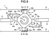
- FIG. 9 is a schematic view illustrating a state where the heat exchanger 20 is inserted into and removed from the housing 10.
- the heat exchanger 20 is rotatable in one direction indicated by a circular arrow of FIG. 8 , and in the other direction indicated by a circular arrow of FIG. 9 .
- a seal member 51 is adhered to the first frame member 221 of the heat exchanger 20 along the frame body 22a.
- An end face 51a of the seal member 51 on a side of the first side plate 11 extends in parallel to a plane A passing through the side 21a of the heat exchange element 21 on the side of the top plate 15, the side 21a thereof on the side of the bottom plate 16, and the axial center 21o of the heat exchange element 21 when the heat exchanger 20 is mounted.
- a seal member 52 is adhered to the second frame member 222 of the heat exchanger 20 along the frame body 22a.
- An end face 52a of the seal member 52 on a side of the second side plate 12 extends in parallel to the plane A.
- a seal member 53 is adhered to the third frame member 223 of the heat exchanger 20 along the frame body 22a.
- An end face 53a of the seal member 53 on a side of the top plate 15 extends in parallel to a plane B passing through the side 21a of the heat exchange element 21 on the side of the first side plate 11, the side 21a thereof on the side of the second side plate 12, and the axial center 21o of the heat exchange element 21 when the heat exchanger 20 is mounted.
- a seal member 54 is adhered to the fourth frame member 224 of the heat exchanger 20 along the frame body 22a.
- An end face 54a of the seal member 54 on a side of the bottom plate 16 extends in parallel to the plane B.
- the heat exchanger 20 is supported by the support members 30.
- the support members 30 are arranged surrounding the heat exchanger 20.
- the support members 30 include a first fixed rail 31 and a second fixed rail 32, which are fixed to the housing 10.
- the support members 30 also include a first movable rail 33 and a second movable rail 34, which are supported by the housing 10 to move in the direction perpendicular to the axial direction X of the heat exchange element 21.
- the first movable rail 33 and the second movable rail 34 also function as rotation force imparting means 60, which imparts to the heat exchanger 20 a rotation force F in one direction indicated by the circular arrow of FIG. 8 .
- the first fixed rail 31 is a rail extending in the axial direction X of the heat exchange element 21.
- the first fixed rail 31 is fixed to the top plate 15 at the central portion of the housing 10.
- the first fixed rail 31 includes a first abutting portion 31a, which extends along the axial direction X of the heat exchange element 21.
- the first abutting portion 31a is formed on the side of the first frame member 221 in one direction. That is, the first abutting portion 31a is formed on the side toward which the first frame member 221 faces in the direction indicated by the circular arrow of FIG. 8 .
- the first abutting portion 31a extends in parallel to the plane A and is formed to be capable of abutting on the end face 51a of the seal member 51 adhered to the first frame member 221. That is, an abutting surface 101 between the end face 51a of the seal member 51 adhered to the first frame member 221 and the first abutting portion 31a of the first fixed rail 31 extends in parallel to the plane A.
- the second fixed rail 32 is a rail extending in the axial direction X of the heat exchange element 21 and is fixed to the bottom plate 16 at the central portion of the housing 10.
- the second fixed rail 32 includes a first abutting portion 32a, which extends along the axial direction X of the heat exchange element 21.
- the first abutting portion 32a is formed on the side of the second frame member 222 in the one direction. That is, the first abutting portion 32a is formed on the side toward which the second frame member 222 faces in the direction indicated by the circular arrow of FIG. 8 .
- the first abutting portion 32a extends in parallel to the plane A and is formed to be capable of abutting on the end face 52a of the seal member 52 adhered to the second frame member 222. That is, an abutting surface 102 between the end face 52a of the seal member 52 adhered to the second frame member 222 and the first abutting portion 32a of the second fixed rail 32 extends in parallel to the plane A.
- the first movable rail 33 and the second movable rail 34 are rails extending in the axial direction X of the heat exchange element 21.
- the first movable rail 33 and the second movable rail 34 are supported by the third side plate 13 and the fourth side plate 14 of the housing 10 to move in the direction perpendicular to the axial direction X of the heat exchange element 21 and the vertical direction Y.
- one of the first movable rail 33 and the second movable rail 34 is provided on one side of the plane A while the other movable rail is provided on the opposite side of the plane A.
- the first movable rail 33 includes a filter support 33b (see FIG.
- the second movable rail 34 includes a filter support 34b (see FIG. 10 ), which supports a filter 46 disposed along the lower edge portion of the heat exchanger 20.
- the first movable rail 33 is disposed above the third frame member 223 and an end portion 17a of the first casing 17 separating the supply air flow path and the exhaust air flow path from each other, the end portion 17a being located on a side of the heat exchanger 20. That is, the first movable rail 33 is disposed on the side of the end portion 17a and third frame member 223 facing the top plate 15. A seal member 55 is adhered to a surface of the first movable rail 33, the surface facing the end portion 17a of the first casing 17. The first movable rail 33 is capable of abutting on the end portion 17a of the first casing 17 via the seal member 55.
- the first movable rail 33 includes a second abutting portion 33a, which extends along the axial direction X of the heat exchange element 21.
- the second abutting portion 33a is formed on the side of the third frame member 223 in the opposite direction. That is, the second abutting portion 33a is formed on the side toward which the third frame member 223 faces in the direction indicated by the circular arrow of FIG. 9 .
- the second abutting portion 33a extends in parallel to the plane B and is formed to be capable of abutting on the end face 53a of the seal member 53 adhered to the third frame member 223. That is, an abutting surface 103 between the end face 53a of the seal member 53 adhered to the third frame member 223 and the second abutting portion 33a of the first movable rail 33 extends in parallel to the plane B.
- the second movable rail 34 is disposed below the fourth frame member 224 and an end portion 18a of the second casing 18 separating the supply air flow path and the exhaust air flow path from each other, the end portion 18a being located on a side of the heat exchanger 20. That is, the second movable rail 34 is disposed on the side of the end portion 18a and fourth frame member 224 facing the bottom plate 16. A seal member 56 is adhered to a surface of the second movable rail 34, the surface facing the end portion 18a of the second casing 18. The second movable rail 34 is capable of abutting on the end portion 18a of the second casing 18 via the seal member 56.
- the second movable rail 34 includes a second abutting portion 34a, which extends along the axial direction X of the heat exchange element 21.
- the second abutting portion 34a is formed on the side of the fourth frame member 224 in the opposite direction. That is, the second abutting portion 34a is formed on the side toward which the fourth frame member 224 faces in the direction indicated by the circular arrow of FIG. 9 .
- the second abutting portion 34a extends in parallel to the plane B and is formed to be capable of abutting on the end face 54a of the seal member 54 adhered to the fourth frame member 224. That is, an abutting surface 104 between the end face 54a of the seal member 54 adhered to the fourth frame member 224 and the second abutting portion 34a of the second movable rail 34 extends in parallel to the plane B.
- the first movable rail 33 is moved upward, that is, toward the top plate 15, such that the first movable rail 33 is disposed away from the end portion 17a of the first casing 17.
- the second movable rail 34 is moved downward, that is, toward the bottom plate 16, such that the second movable rail 34 is disposed away from the end portion 18a of the second casing 18. Consequently, as illustrated in FIG. 9 , the seal member 51 adhered to the first frame member 221 of the heat exchanger 20 is spaced away from the first abutting portion 31a of the first fixed rail 31.
- the seal member 52 adhered to the second frame member 222 is spaced away from the first abutting portion 32a of the second fixed rail 32.
- the seal member 53 adhered to the third frame member 223 is spaced away from the second abutting portion 33a of the first movable rail 33.
- the seal member 54 adhered to the fourth frame member 224 is spaced away from the second abutting portion 34a of the second movable rail 34.
- the heat exchanger 20 can be easily slid and inserted into the housing 10 from the maintenance opening 130 formed in the third side plate 13.
- the seal members 51, 52, 53, and 54 can be satisfactorily protected because the seal members 51, 52, 53, 54 can avoid contacts with the first fixed rail 31, the second fixed rail 32, the first movable rail 33, and the second movable rail 34 when the heat exchanger 20 is inserted into the housing 10.
- the first movable rail 33 is moved downward, that is, toward the bottom plate 16 and fixed, such that the seal member 55 of the first movable rail 33 is pressed against the end portion 17a of the first casing 17 while the second abutting portion 33a of the first movable rail 33 is pressed against the end face 53a of the seal member 53 adhered to the third frame member 223.
- the second abutting portion 33a of the first movable rail 33 presses the third frame member 223 downward via the end face 53a of the seal member 53.
- the second movable rail 34 is moved upward, that is, toward the top plate 15 and fixed, such that the seal member 56 of the second movable rail 34 is pressed against the end portion 18a of the second casing 18 while the second abutting portion 34a of the second movable rail 34 is pressed against the end face 54a of the seal member 54 adhered to the fourth frame member 224.
- the second abutting portion 34a of the second movable rail 34 presses the fourth frame member 224 upward via the end face 54a of the seal member 54.
- the static pressure at a connection between a duct (not illustrated) and the housing 10 is reduced, so that the capacity of a motor for blowing air to the heat exchange ventilator 1 can be reduced to suppress the power consumption.
- the abutting surface 101 between the end face 51a of the seal member 51 adhered to the first frame member 221 and the first abutting portion 31a of the first fixed rail 31, and the abutting surface 102 between the end face 52a of the seal member 52 adhered to the second frame member 222 and the first abutting portion 32a of the second fixed rail 32 extend in parallel to the plane A.
- the abutting surface 103 between the end face 53a of the seal member 53 adhered to the third frame member 223 and the second abutting portion 33a of the first movable rail 33, and the abutting surface 104 between the end face 54a of the seal member 54 adhered to the fourth frame member 224 and the second abutting portion 34a of the second movable rail 34 extend in parallel to the plane B.
- the first movable rail 33 is moved upward away from the end portion 17a of the first casing 17 and the end face 53a of the seal member 53 adhered to the third frame member 223 while the second movable rail 34 is moved downward away from the end portion 18a of the second casing 18 and the end face 54a of the seal member 54 adhered to the fourth frame member 224.
- the rotation force F in the one direction imparted from the first movable rail 33 and the second movable rail 34 to the heat exchanger 20 when the heat exchanger 20 is mounted is removed, thereby allowing rotation of the heat exchanger 20 in the other direction indicated by the circular arrow of FIG. 9 .
- the heat exchanger 20 When the heat exchanger 20 is manipulated via the maintenance opening 130 of the third side plate 13 of the housing 10 for rotation in the other direction indicated by the circular arrow of FIG. 9 , the end face 51a of the seal member 51 adhered to the first frame member 221 can move away from the first fixed rail 31, and the end face 52a of the seal member 52 adhered to the second frame member 222 can move away from the second fixed rail 32. As a result, the heat exchanger 20 can be easily slid and removed from the housing 10.
- the seal members 51, 52, 53, and 54 can be satisfactorily protected because the seal members 51, 52, 53, and 54 can avoid contacts with the first fixed rail 31, the second fixed rail 32, the first movable rail 33, and the second movable rail 34 when the heat exchanger 20 is removed from the housing 10.
- FIG. 10 is a front view illustrating the heat exchange ventilator 1 when the heat exchanger 20 is mounted
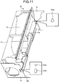
- FIG. 11 is an exploded perspective view illustrating a location where the first movable rail 33 is mounted to the housing 10.
- FIG. 10 illustrates a state in which the maintenance cover 40 is removed from the third side plate 13.
- the third side plate 13 of the housing 10 includes a first fastening hole 131a and a first long hole 131b provided for mounting the first movable rail 33.
- the first long hole 131b is formed under the first fastening hole 131a. That is, the first long hole 131b is formed on the side of the first fastening hole 131a closer to the bottom plate 16.
- the first long hole 131b extends in the direction perpendicular to the axial direction X of the heat exchange element 21 and in the vertical direction Y.
- the fourth side plate 14 of the housing 10 includes a first coupling hole 141a provided for mounting the first movable rail 33.
- the first coupling hole 141a is a single hole including a small diameter portion and a large diameter portion connected to the small diameter portion.
- the small diameter portion is formed over the large diameter portion. That is, the small diameter portion is formed on the side of the large diameter portion closer to the top plate 15.
- FIG. 12 is a cross-sectional view illustrating a mounting portion of the first movable rail 33 on the third side plate 13
- FIG. 13 is a cross-sectional view illustrating a mounting portion of the first movable rail 33 on the fourth side plate 14.
- an end portion of the first movable rail 33 on the side of the third side plate 13 includes screw holes having internal threads formed therein, and screws 71 and 72 are screwed into these screw holes.
- the first movable rail 33 is fastened and fixed to the third side plate 13 by the screw 71 inserted into the first fastening hole 131a of the third side plate 13 and the screw 72 inserted into a lower portion of the first long hole 131b of the third side plate 13.
- an end portion of the first movable rail 33 on the side of the fourth side plate 14 includes a screw hole having an internal thread therein, and a screw 73 is screwed through this screw hole of the end portion of the rail 33 and hooked on the small diameter portion of the first coupling hole 141a.
- the screw 73 is screwed into the screw hole in advance.
- a head of the screw 73 is sized to pass through the large diameter portion of the first coupling hole 141a.
- the first movable rail 33 presses the third frame member 223 of the heat exchanger 20 from above, that is, from the side of the top plate 15.
- the first movable rail 33 receives an upward force acting as a reaction force from the heat exchanger 20.
- the head of the screw 73 is hooked on the small diameter portion of the first coupling hole 141a, thus, it is possible to fix the first movable rail 33 to the fourth side plate 14.
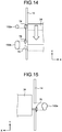
- FIG. 14 is a cross-sectional view illustrating a mounting portion of the second movable rail 34 on the third side plate 13
- FIG. 15 is a cross-sectional view illustrating a mounting portion of the second movable rail 34 on the fourth side plate 14.
- the third side plate 13 of the housing 10 includes a second fastening hole 132a and a second long hole 132b provided for mounting the second movable rail 34.
- the second long hole 132b is formed under the second fastening hole 132a. That is, the second long hole 132b is formed on the side of the second fastening hole 132a closer to the bottom plate 16.
- the second long hole 132b extends in the direction perpendicular to the axial direction X of the heat exchange element 21 and in the vertical direction Y.
- the fourth side plate 14 of the housing 10 includes a second coupling hole 142a provided for mounting the second movable rail 34.
- the second coupling hole 142a is a single hole including a small diameter portion and a large diameter portion connected to the small diameter.
- the small diameter portion is formed under the large diameter portion. That is, the smaller diameter is formed on the side of the large diameter portion closer to the bottom plate 16.
- an end portion of the second movable rail 34 on the side of the third side plate 13 includes screw holes having internal threads formed therein, and screws 74 and 75 are screwed into these screw holes.
- the second movable rail 34 is fastened and fixed to the third side plate 13 by the screw 74 inserted into the second fastening hole 132a of the third side plate 13 and the screw 75 inserted into an upper portion of the second long hole 132b of the third side plate 13.
- an end portion of the second movable rail 34 on the side of the fourth side plate 14 includes a screw hole having an internal thread formed therein, and the screw 76 is screwed through this screw hole and hooked on the small diameter portion of the second coupling hole 142a.
- the screw 76 is screwed into the screw hole in advance.
- a head of the screw 76 is sized to pass through the large diameter portion of the second coupling hole 142a.
- the second movable rail 34 when the second movable rail 34 is fastened and fixed to the third side plate 13, the second movable rail 34 receives a downward force acting as a reaction force from the heat exchanger 20. As long as the head of the screw 76 is hooked on the small diameter portion of the second coupling hole 142a, thus, it is possible to fix the second movable rail 34 to the fourth side plate 14.
- each of the first movable rail 33 and the second movable rail 34 is fixed to the housing 10 at its one end, that is, at the end portion thereof on the side of the fourth side plate 14 while each of the first movable rail 33 and the second movable rail 34 is supported at the other end, that is, at the end portion thereof on the side of the third side plate 13 to move in the direction perpendicular to the axial direction X of the heat exchange element 21.
- the first movable rail 33 is hooked on the small diameter portion of the first coupling hole 141a by the screw 73 while the second movable rail 34 is hooked on the small diameter portion of the second coupling hole 142a by the screw 76.
- the first movable rail 33 and the second movable rail 34 can be easily attached to and detached from the housing 10.
- this end portion may have a projection capable of being inserted into the large diameter portion of the first coupling hole 141a and hooked on the small diameter portion thereof.
- this end portion may have a projection capable of being inserted into the large diameter portion of the second coupling hole 142a and hooked on the small diameter portion thereof.
- the frame members 22 each mounted to the corresponding one of the sides 21a extending along the axial direction X of the heat exchange element 21 are movable along with the deformation of the heat exchange element 21.
- the heat exchange element 21 is deformed by the long-term use, it is possible to satisfactorily suppress the deformation of the frame members 22, the unsticking of the frame members 22 from the heat exchange element 21, and the deformation of or damage to the heat exchange element 21.
- the heat exchanger 20 further includes the cover members 23 each covering the end face 21b perpendicular to the axial direction X of the heat exchange element 21, the frame members 22 being connected to the cover members 23.
- the gaps 25 and 26, which allow each frame member 22 to move along the direction perpendicular to the axial direction X of the heat exchange element 21 are provided in each of the coupling portions 24 at which the frame members 22 are connected to the cover members 23.
- the gaps 25 and 26 have the same length for each of the connecting portions 24 at which the frame members 22 are connected to the cover members 23. This makes it possible to suppress the uneven amounts of movements of the frame members 22 positioned on the diagonal line, thus satisfactorily suppressing the displacement of the axial center 21o of the heat exchange element 21 from the position in which the heat exchanger 20 is initially mounted.
- the gaps 25 and 26 may have different lengths for each of the connecting portions 24 at which the frame members 22 are connected to the cover members 23.
- the length of the gaps 25 and 26 is set to be half the maximum contraction length of the heat exchange element 21
- the length of the gaps 25 and 26 may be set to be the maximum contraction length of the heat exchange element 21.
- the connecting portion 24 includes the protrusion 22b and the recess 23b.
- the protrusion 22b extends from the one end of the frame member 22 in the direction perpendicular to the axial direction X of the heat exchange element 21.
- the recess 23b is formed in the corner portion 231 of the opposite surface of the cover member 23 to the end face 21b of the heat exchange element 21, and is recessed toward the end face 21b.
- the protrusion 22b fits in the recess 23b such that the protrusion 22b is slidable in the direction perpendicular to the axial direction X of the heat exchange element 21.
- the gap 25 is provided between the protrusion distal end 22c of the protrusion 22b and the recess proximal end 23d of the recess 23b.
- the gap 26 is provided between the recess distal end 23c of the recess 23b and the protrusion proximal end 22d of the protrusion 22b.
- the protrusion 22b includes the frame-side hooking portions 22t
- the recess 23b includes the cover-side hooking portions 23t, which can be hooked on the frame-side hooking portions 22t.
- the frame-side hooking portions 22t and the cover-side hooking portions 23t are formed to be connectable to each other by snap fitting. Thus, it is it possible to easily connect the frame-side hooking portions 22t and the cover-side hooking portions 23t to each other.
- the configuration of the connecting portion 24 is not limited to that described in the first embodiment as long as the configuration allows the movement of the frame members 22 in the direction perpendicular to the axial direction X of the heat exchange element 21.
- the protrusions 22b of the frame members 22 may have depressions provided on both side portions thereof extending in the direction perpendicular to the axial direction X of the protrusions 22b of the frame members 22 while the recesses 23b of the cover members 23 may have projections formed on both side portions thereof, the projections being capable of being hooked on the depressions of the protrusions 22b.
- each recess 23b of the cover members 23 may have a cover-side hooking portion formed thereat, the cover-side hooking portion extending toward the recess distal end 23c and having a hook shape while the protrusion distal end 22c of each protrusion 22b of the frame members 22 may have a frame-side hooking portion capable of hooking the cover-side hooking portion.
- a recess may be formed on a surface of each protrusion 22b of the frame members 22 on the side of the frame body 22a, and a protrusion slidably fitting in the recess may be formed at each corner portion 231 of the cover members 23.
- Each frame member 22 may be disposed in such a position as to form a gap between the frame-side hooking portions 22t and the cover-side hooking portions 23t without hooking the frame-side hooking portions 22t of the frame members 22 and the cover-side hooking portions 23t of the cover members 23 on each other.
- each frame member 22 can move in a direction away from the axial center 21o of the heat exchange element 21 along with the expansion of the heat exchange element 21 if such an expansion occurs due to the element 21 absorbing water.
- the abutting surfaces between the support members 30 and the frame members 22, that is, the abutting surface 101 between the end face 51a of the seal member 51 adhered to the first frame member 221 and the first abutting portion 31a of the first fixed rail 31, and the abutting surface 102 between the end face 52a of the seal member 52 adhered to the second frame member 222 and the first abutting portion 32a of the second fixed rail 32 extend in parallel to the plane A.
- the abutting surface 103 between the end face 53a of the seal member 53 adhered to the third frame member 223 and the second abutting portion 33a of the first movable rail 33, and the abutting surface 104 between the end face 54a of the seal member 54 adhered to the fourth frame member 224 and the second abutting portion 34a of the second movable rail 34 extend in parallel to the plane B.
- the seal members 51, 52, 53 and 54 may be omitted and the frame member may abut directly on the corresponding abutting portion. That is, the first frame member 221 may abut directly on the first abutting portion 31a of the first fixed rail 31.
- the second frame member 222 may abut directly on the first abutting portion 32a of the second fixed rail 32.
- the third frame member 223 may abut directly on the second abutting portion 33a of the first movable rail 33.
- the fourth frame member 224 may abut directly on the second abutting portion 34a of the second movable rail 34.
- FIG. 16 is a schematic plan view illustrating a heat exchange ventilator 1B according to a second embodiment.
- the heat exchange ventilator 1B includes a separating plate 19 for forming a bypass flow path V to guide the exhaust air flow in the exhaust flow path from the upstream side of the heat exchanger 20 to the downstream side of the heat exchanger 20, as illustrated in the figure.
- the separating plate 19 is provided closer to the fourth side plate 14 than the heat exchanger 20 is, and is fixed to the housing 10.
- the end face of the heat exchanger 20 on the side of the fourth side plate 14 abuts on the separating version 19 when the heat exchanger 20 is mounted to the housing 10.
- the separating plate 19 may form a bypass flow path to guide the supply air flow in the supply air flow path from the upstream side of the heat exchanger 20 to the downstream side of the heat exchanger 20.
- the separating plate 19 includes a first coupling hole 191a and a second coupling hole 192a formed therein.
- the first coupling hole 191a has the same shape as the first coupling hole 141a formed in the fourth side plate 14 of the heat exchange ventilator 1 according to the first embodiment.
- the second coupling hole 192a has the same shape as the second coupling hole 142a formed in the fourth side plate 14 of the heat exchange ventilator 1 according to the first embodiment.
- the screw 76 is hooked on a small diameter portion of the second coupling hole 192a of the separating plate 19, which is a component fixed to the housing 10.
- the structure of the mounting portion at the other end, that is, the end portion of each of the first movable rail 33 and the second movable rail 34 on the side of the third side plate 13 is similar to that of the heat exchange ventilator 1 according to the first embodiment.
- each of the first movable rail 33 and the second movable rail 34 is fixed at one end thereof to the component fixed to the housing 10, that is, the separating plate 19, and is supported at the other end thereof by the third side plate 13 of the housing 10 to move in a direction perpendicular to the axial direction X of the heat exchange element 21.
- the first movable rail 33 and the second movable rail 34 with a range of movement in the direction perpendicular to the axial direction of the heat exchange element 21, without removing the first movable rail 33 and the second movable rail 34 from the housing 10 and the separating plate 19.
- each of the first and second movable rails may be supported at the end portion thereof on the side of the third side plate 13 of the housing 10 by a member fixed to the housing 10 different from the third side plate 13, such that each movable rail can move in the direction perpendicular to the axial direction X of the heat exchange element 21.
- each of the first movable rail 33 and the second movable rail 34 may be supported at the end portion thereof mounted to the separating plate 19 to move in the direction perpendicular to the axial direction X of the heat exchange element 21, as with the end portion on the side of the third side plate 13.
- the present invention is applied to the heat exchange ventilators 1 and 1B, which are total heat exchange-type ventilators, but the present invention may be applied to a sensible heat exchange-type ventilator.
- a single heat exchanger 20 is used, but a plurality of heat exchangers 20 may be inserted in series into the housing 10. In that case, a seal member is disposed between the heat exchangers 20 to ensure airtightness between the heat exchangers 20.
- 1 heat exchange ventilator 10 housing; 11 first side plate; 111 outdoor-side inlet; 112 outdoor-side exhaust port; 12 second side plate; 121 indoor-side inlet; 122 indoor-side outlet; 13 third side plate; 130 maintenance opening; 131a first fastening hole; 131b first long hole; 132a second fastening hole; 132b second long hole; 14 fourth side plate; 141a first coupling hole; 142a second coupling hole; 15 top plate; 16 bottom plate; 17 first casing; 17a end portion; 18 second casing; 18a end portion; 19 separating plate; 191a first coupling hole; 192a second coupling hole; 20 heat exchanger; 20a corner portion; 21 heat exchange element; 21a side; 21b end face; 21o axial center; 22 frame member; 22a frame body; 22b protrusion; 22c protrusion distal end; 22d protrusion proximal end; 22t frame-side hooking portion; 221 first frame member; 222 second frame member; 223 third frame member; 224
Landscapes
- Engineering & Computer Science (AREA)
- Mechanical Engineering (AREA)
- General Engineering & Computer Science (AREA)
- Physics & Mathematics (AREA)
- Thermal Sciences (AREA)
- Chemical & Material Sciences (AREA)
- Combustion & Propulsion (AREA)
- Heat-Exchange Devices With Radiators And Conduit Assemblies (AREA)
- Details Of Heat-Exchange And Heat-Transfer (AREA)
- Chemical Kinetics & Catalysis (AREA)
- Materials Engineering (AREA)
- Organic Chemistry (AREA)
Description
- The present invention relates to a heat exchanger to perform heat exchange between a supply air flow and an exhaust air flow, and a heat exchange ventilator to perform ventilation while allowing the heat exchanger to perform the heat exchange.
- Conventionally, a heat exchange ventilator including a heat exchanger to perform heat exchange between a supply air flow and an exhaust air flow has been known as a ventilator to perform ventilation in a building. For example,
Patent Literature 1 discloses a heat exchange ventilator. For the disclosed ventilator, a corner guide (frame member) is adhered to each corner portion of a heat exchange element of the heat exchanger and fixed to covers each covering an end face of the heat exchange element, thereby protecting the corner portions of the heat exchange element and ensuring airtightness at abutting portions between a heat exchange ventilator body and the heat exchange element. -
JP H06-313694 A
channel, and forming cutout holes at edges of the frame. The heat exchanger ofJP H06-313694 A - Patent Literature 1: Japanese Patent Application Laid-open No.
2008-25982 - Unfortunately, a heat exchange element generally formed of specially processed paper tends to contract due to long-term use because the heat exchange element repeats drying and wetting due to air passing through the heat exchange element. For the configuration of
Patent Literature 1, the frame member adhered to each corner portion of the heat exchange element is fixed to the covers. Thus, the contraction of the heat exchange element deforms the frame member, unsticks the heat exchange element and the frame member from each other, or deforms or damages the heat exchange element. As a result, a gap is formed between the heat exchange element and each frame member, and inside the heat exchange element. Airflow leaks from one of the supply air flow path and the exhaust air flow path to the other through the gap. Such an airflow leakage poses problems such as the change in an amount of ventilation of air, the mixing of contaminant elements contained in the exhaust air flow, into the supply air flow, and the reduction in the heat exchange efficiency. - The present invention has been made in view of the above, and it is an object of the present invention to provide a heat exchanger and a heat exchange ventilator capable of suppressing occurrence of leakage of airflow between a supply air flow and an exhaust air flow even if a heat exchange element contracts due to the long-term use. Solution to Problem
- To solve the above problem and achieve the object, the present invention provides a heat exchanger as defined by
claim 1. - The heat exchanger and the heat exchange ventilator of the present invention have an effect of suppressing the occurrence of the leakage of airflow between the supply air flow and the exhaust air flow even if the heat exchange element contracts due to the long-term use.
-
-
FIG. 1 is a schematic front view illustrating a heat exchange ventilator according to a first embodiment. -
FIG. 2 is a schematic plan view illustrating the heat exchange ventilator according to the first embodiment. -
FIG. 3 is an exploded perspective view illustrating a heat exchanger according to the first embodiment. -
FIG. 4 is an enlarged view of relevant parts of the heat exchanger according to the first embodiment. -
FIG. 5 is an explanatory view illustrating a connecting portion between a frame member and a cover member of the heat exchanger according to the first embodiment. -
FIG. 6 is an explanatory view illustrating the connecting portion between the frame member and the cover member of the heat exchanger according to the first embodiment. -
FIG. 7 is a schematic view illustrating a direction in which the heat exchange element of the heat exchanger according to the first embodiment contracts. -
FIG. 8 is a schematic view illustrating a state where the heat exchanger is mounted in a housing. -
FIG. 9 is a schematic view illustrating a state where the heat exchanger is inserted into and removed from the housing. -
FIG. 10 is a front view illustrating the heat exchange ventilator when the heat exchanger is mounted. -
FIG. 11 is an exploded perspective view illustrating a location where a first movable rail is mounted to the housing. -
FIG. 12 is a cross-sectional view illustrating a mounting portion of the first movable rail on a third side plate. -
FIG. 13 is a cross-sectional view illustrating a mounting portion of the first movable rail on a fourth side plate. -
FIG. 14 is a cross-sectional view illustrating a mounting portion of a second movable rail on the third side plate. -
FIG. 15 is a cross-sectional view illustrating a mounting portion of the second movable rail on the fourth side plate. -
FIG. 16 is a schematic plan view illustrating a heat exchange ventilator according to a second embodiment. - Hereinafter, a heat exchanger and a heat exchange ventilator according to each embodiment of the present invention will be described in detail with reference to the drawings. The invention is not limited to the embodiments.
-
FIG. 1 is a schematic front view illustrating aheat exchange ventilator 1 according to a first embodiment, andFIG. 2 is a schematic plan view illustrating theheat exchange ventilator 1 according to the first embodiment. Theheat exchange ventilator 1 is a total-heat-exchanger-type ventilator mounted in an attic for supplying and discharging air through a duct (not illustrated). Theheat exchange ventilator 1 includes ahousing 10, aheat exchanger 20, and a plurality ofsupport members 30. Thehousing 10 defines an outer contour of the ventilator. Theheat exchanger 20 is in a prism shape (quadrangular prism shape in the first embodiment), and accommodated in thehousing 10 such that theheat exchanger 20 can be inserted into and removed from thehousing 10. Thesupport members 30 support theheat exchanger 20 in thehousing 10. - The
housing 10 is formed as a hexahedron which includes afirst side plate 11, asecond side plate 12, athird side plate 13, afourth side plate 14, atop plate 15, and abottom plate 16. Thefirst side plate 11 is disposed on an outdoor side. Thesecond side plate 12 is opposite to thefirst side plate 11 and is disposed on an indoor side. Thethird side plate 13 extends between thefirst side plate 11 and thesecond side plate 12. Thefourth side plate 14 is opposite to thethird side plate 13 and extends between thefirst side plate 11 and thesecond side plate 12. Thetop plate 15 is mounted to upper portions of thefirst side plate 11, thesecond side plate 12, thethird side plate 13, and thefourth side plate 14. Thebottom plate 16 is mounted to lower portions of thefirst side plate 11, thesecond side plate 12, thethird side plate 13, and thefourth side plate 14. When theheat exchange ventilator 1 is installed, thehousing 10 is disposed such that thetop plate 15 is positioned on an upper side in a vertical direction Y and thebottom plate 16 is positioned on a lower side in the vertical direction Y. - The
first side plate 11 includes an outdoor-side inlet 111, which draws outdoor air, and an outdoor-side exhaust port 112, which discharges indoor air to the outdoors. Thesecond side plate 12 includes an indoor-side inlet 121, which draws indoor air, and an indoor-side outlet 122, which supplies the indoor space with outdoor air drawn from the outdoor-side inlet 111. As illustrated inFIG. 2 , thethird side plate 13 includes amaintenance opening 130, which allows theheat exchanger 20 to be inserted into and removed from thehousing 10. Moreover, amaintenance cover 40, which closes themaintenance opening 130, is detachably mounted to thethird side plate 13. Aseal member 41 adhered to the inside of themaintenance cover 40 abuts on an end face of theheat exchanger 20 and an inner peripheral surface of themaintenance opening 130. - The
housing 10 includes afirst casing 17 and asecond casing 18, which define a supply air flow path and an exhaust air flow path as flow paths independent of each other. The outdoor-side inlet 111 and indoor-side outlet 122 communicate with each other by the supply air flow path, and the supply air flow path directs a supply air flow in a direction of solid arrows illustrated inFIG. 1 . The indoor-side inlet 121 and the outdoor-side exhaust port 112 communicate with each other by the exhaust air flow path, and the exhaust air flow path directs an exhaust air flow in a direction of broken arrows illustrated inFIG. 1 . Thefirst casing 17 holds anexhaust air blower 42, which is disposed in the middle of the exhaust air flow path for generating an exhaust air flow. Thesecond casing 18 holds asupply air blower 43, which is disposed in the middle of the supply air flow path for generating a supply air flow. - As illustrated in
FIG. 1 , theheat exchanger 20 is disposed in a central portion of thehousing 10 in the middle of the supply air flow path and the middle of the exhaust air flow path, and forms a part of the supply air flow path and the exhaust air flow path. As illustrated inFIG. 1 ,corner portions 20a at four corners of theheat exchanger 20 are supported by thesupport members 30 fixed to thehousing 10. - A configuration of the
heat exchanger 20 according to the first embodiment will be described.FIG. 3 is an exploded perspective view of theheat exchanger 20, andFIG. 4 is an enlarged view of relevant parts of theheat exchanger 20. Theheat exchanger 20 includes a prism-shapedheat exchange element 21, fourframe members 22, and twocover members 23. The fourframe members 22 are mounted in a one-to-one relationship, tosides 21a extending along an axial direction X of theheat exchange element 21. The twocover members 23 cover end faces 21b perpendicular to the axial direction X of theheat exchange element 21, and theframe members 22 are connected to the twocover members 23. In the first embodiment, there are fourframe members 22, but the number offrame members 22 is not limited to four. - The
heat exchange element 21 is formed of specially processed paper and is in a prismatic shaped having a square cross-section taken along a plane perpendicular to the axial direction X. Theheat exchange element 21 may have a rectangular cross-section taken along a plane perpendicular to the axial direction X, or a polygonal cross-section taken along a plane perpendicular to the axial direction X. That is, theheat exchanger 20 may be in a polygonal prism shape. Although a detailed configuration of theheat exchange element 21 is not illustrated, theheat exchange element 21 includes a plurality of supply air passages through which supply air passes and a plurality of exhaust air passages through which exhaust air passes. Each supply air passage and each exhaust air passage intersect, and act as the flow paths independent of each other. - As illustrated in
FIGS. 3 and4 , eachframe member 22 includes aframe body 22a extending along the axial direction X of theheat exchange element 21, andprotrusions 22b extending in a direction perpendicular to the axial direction X of theheat exchange element 21 at both ends of theframe body 22a. Theframe body 22a is formed to be capable of abutting on theside 21a of theheat exchange element 21. Theframe body 22a has a portion to abut on theside 21a, and an adhesive or a sealant is applied to this portion of theframe body 22a. Consequently, eachframe member 22 is fixed to eachside 21a of theheat exchange element 21 by adhesion. - As illustrated in
FIG. 4 , eachcover member 23 includes acover body 23a and a plurality ofrecesses 23b. Thecover body 23a is in a rectangular shape along theend face 21b of theheat exchange element 21 and abuts on theend face 21b. Therecesses 23b are formed incorner portions 231 at four corners of a surface of thecover body 23a, the surface being opposite to the surface abutting on theend face 21b of theheat exchange element 21. The recessed 23b are recessed toward theend face 21b of theheat exchange element 21. Ahandle 44 used at a time of maintenance operation is mounted to the surface of thecover body 23a, the surface being opposite to theheat exchange element 21. - Each of the
frame members 22 is connected to thecover members 23 at a connectingportion 24. The connectingportion 24 includes theprotrusion 22b of theframe member 22 and therecess 23b of thecover member 23.FIGS. 5 and 6 are explanatory views each illustrating the connectingportion 24 at which theframe member 22 are connected to thecover member 23 of theheat exchanger 20. As illustrated inFIG. 5 , theprotrusion 22b of theframe member 22 fits in therecess 23b of thecover member 23 such that theprotrusion 22b can slide in the direction perpendicular to the axial direction X of theheat exchange element 21, and covers therecess 23b from a side opposite to theheat exchange element 21. - As illustrated in
FIG. 5 , theprotrusion 22b of theframe member 22 includes frame-side hooking portions 22t protruding inwardly from the both side portions between adistal end 22c of theprotrusion 22b (hereinafter referred to as a protrusiondistal end 22c) and aproximal end 22d of theprotrusion 22b (hereinafter referred to as a protrusionproximal end 22d). Therecess 23b of thecover member 23 includes two cover-side hooking portions 23t each having a hook shape that can be hooked on the frame-side hooking portion 22t. The frame-side hooking portions 22t are connectable to the cover-side hooking portions 23t by snap fitting. It is thus possible to prevent theprotrusion 22b and therecess 23b from coming off easily, and hence suppress disengagement of eachframe member 22 from thecover members 23 in mounting one end of theframe member 22 and subsequently mounting the other end thereof during the assemblage. This achieves the easy connecting operation. The abutment of thecover members 23 on the end faces 21b of theheat exchange element 21 and the connection of eachframe member 22 adhered to theside 21a of theheat exchange element 21 to thecover members 23, as described above, can stably keep the shape of theheat exchange element 21 formed of the specially processed paper. - As illustrated in
FIG. 5 ,gaps portion 24 at which theframe member 22 and thecover member 23 are connected to each other. Thegaps frame member 22 to move along the direction perpendicular to the axial direction X of theheat exchange element 21. Thegap 25 is provided between the protrusiondistal end 22c of theprotrusion 22b of theframe member 22 and a recessproximal end 23d of therecess 23b of thecover member 23. Thegap 26 is provided between the protrusionproximal end 22d of theprotrusion 22b of theframe member 22 and a recessdistal end 23c of therecess 23b of thecover member 23. In the first embodiment, the recessdistal end 23c is a distal end of the cover-side hooking portion 23t. - When the
heat exchange ventilator 1 is used for a long period of time, theheat exchange element 21 may swell and contract through repetitious drying and wetting due to air passing through theheat exchange ventilator 1.FIG. 7 is a schematic view illustrating a direction in which theheat exchange element 21 contracts. Theheat exchange element 21 contracts toward an axial center 21o. In theheat exchanger 20 of the first embodiment, as described above, thegaps frame member 22 to move along the direction perpendicular to the axial direction X of theheat exchange element 21 are provided in each of the connectingportions 24 at which theframe members 22 are connected to thecover members 23. This structure enables eachframe member 22 to move in a direction toward the axial center 21o of theheat exchange element 21 by a distance corresponding to thegaps FIG. 6 , even if theheat exchange element 21 contracts toward the axial center 21o. - For the
heat exchange ventilator 1, as described above, when theheat exchange element 21 contracts toward the axial center 21o due to the long-term use, theframe members 22 move along with the deformation of theheat exchange element 21, thereby satisfactorily suppressing deformation of theframe members 22, unsticking of theframe members 22 from theheat exchange element 21, and deformation of or damage to theheat exchange element 21. Accordingly, theheat exchange ventilator 1 prevents a gap from being formed between theheat exchange element 21 and eachframe member 22 and from being formed inside theheat exchange element 21, and thus satisfactorily suppresses change in the amount of ventilation of air due to leakage of airflow from one of the supply air flow path and the exhaust air flow path to the other, mixing of contaminant elements contained in the exhaust airflow, into the supply air flow, and reduction in the heat exchange efficiency. - In the first embodiment, preferably, all the
gaps heat exchange element 21 contracts due to the long-term use. Since all thegaps frame members 22 positioned on the diagonal line, thus satisfactorily suppressing displacement of the axial center 21o of theheat exchange element 21 from the original position at the time theheat exchange element 21 is initially mounted. - Since the length of the
gaps heat exchange element 21, theframe members 22 move along with the deformation of theheat exchange element 21 by at least the distance corresponding to thegaps frame members 22, the unsticking of theframe members 22 from theheat exchange element 21, and the deformation of or damage to theheat exchange element 21. - Next, a supporting structure of the
heat exchanger 20 in thehousing 10 will be described. In the following description, theframe member 22 mounted to theside 21a of theheat exchange element 21 on a side of the top plate 15 (upper side inFIG. 1 ) is referred to as afirst frame member 221. Theframe member 22 mounted to theside 21a of theheat exchange element 21 on a side of the bottom plate 16 (lower side inFIG. 1 ) is referred to as asecond frame member 222. Theframe member 22 mounted to theside 21a of theheat exchange element 21 on a side of the first side plate 11 (left side inFIG. 1 ) is referred to as athird frame member 223. Theframe member 22 mounted to theside 21a of theheat exchange element 21 on a side of the second side plate 12 (right side inFIG. 1 ) is referred to as afourth frame member 224. -
FIG. 8 is a schematic view illustrating a state where theheat exchanger 20 is mounted in thehousing 10 andFIG. 9 is a schematic view illustrating a state where theheat exchanger 20 is inserted into and removed from thehousing 10. As illustrated inFIGS. 8 and9 , in thehousing 10, theheat exchanger 20 is rotatable in one direction indicated by a circular arrow ofFIG. 8 , and in the other direction indicated by a circular arrow ofFIG. 9 . - As illustrated in
FIG. 8 , aseal member 51 is adhered to thefirst frame member 221 of theheat exchanger 20 along theframe body 22a. Anend face 51a of theseal member 51 on a side of thefirst side plate 11 extends in parallel to a plane A passing through theside 21a of theheat exchange element 21 on the side of thetop plate 15, theside 21a thereof on the side of thebottom plate 16, and the axial center 21o of theheat exchange element 21 when theheat exchanger 20 is mounted. Aseal member 52 is adhered to thesecond frame member 222 of theheat exchanger 20 along theframe body 22a. Anend face 52a of theseal member 52 on a side of thesecond side plate 12 extends in parallel to the plane A. - A
seal member 53 is adhered to thethird frame member 223 of theheat exchanger 20 along theframe body 22a. Anend face 53a of theseal member 53 on a side of thetop plate 15 extends in parallel to a plane B passing through theside 21a of theheat exchange element 21 on the side of thefirst side plate 11, theside 21a thereof on the side of thesecond side plate 12, and the axial center 21o of theheat exchange element 21 when theheat exchanger 20 is mounted. Aseal member 54 is adhered to thefourth frame member 224 of theheat exchanger 20 along theframe body 22a. Anend face 54a of theseal member 54 on a side of thebottom plate 16 extends in parallel to the plane B. - As described above, the
heat exchanger 20 is supported by thesupport members 30. As illustrated inFIG. 8 , thesupport members 30 are arranged surrounding theheat exchanger 20. Thesupport members 30 include a first fixedrail 31 and a second fixedrail 32, which are fixed to thehousing 10. Thesupport members 30 also include a firstmovable rail 33 and a secondmovable rail 34, which are supported by thehousing 10 to move in the direction perpendicular to the axial direction X of theheat exchange element 21. The firstmovable rail 33 and the secondmovable rail 34 also function as rotation force imparting means 60, which imparts to theheat exchanger 20 a rotation force F in one direction indicated by the circular arrow ofFIG. 8 . - The first fixed
rail 31 is a rail extending in the axial direction X of theheat exchange element 21. The first fixedrail 31 is fixed to thetop plate 15 at the central portion of thehousing 10. The first fixedrail 31 includes a firstabutting portion 31a, which extends along the axial direction X of theheat exchange element 21. The firstabutting portion 31a is formed on the side of thefirst frame member 221 in one direction. That is, the first abuttingportion 31a is formed on the side toward which thefirst frame member 221 faces in the direction indicated by the circular arrow ofFIG. 8 . The firstabutting portion 31a extends in parallel to the plane A and is formed to be capable of abutting on theend face 51a of theseal member 51 adhered to thefirst frame member 221. That is, an abuttingsurface 101 between theend face 51a of theseal member 51 adhered to thefirst frame member 221 and the first abuttingportion 31a of the first fixedrail 31 extends in parallel to the plane A. - The second fixed
rail 32 is a rail extending in the axial direction X of theheat exchange element 21 and is fixed to thebottom plate 16 at the central portion of thehousing 10. The second fixedrail 32 includes a firstabutting portion 32a, which extends along the axial direction X of theheat exchange element 21. The firstabutting portion 32a is formed on the side of thesecond frame member 222 in the one direction. That is, the first abuttingportion 32a is formed on the side toward which thesecond frame member 222 faces in the direction indicated by the circular arrow ofFIG. 8 . The firstabutting portion 32a extends in parallel to the plane A and is formed to be capable of abutting on theend face 52a of theseal member 52 adhered to thesecond frame member 222. That is, an abuttingsurface 102 between theend face 52a of theseal member 52 adhered to thesecond frame member 222 and the first abuttingportion 32a of the second fixedrail 32 extends in parallel to the plane A. - As illustrated in
FIG. 2 , the firstmovable rail 33 and the secondmovable rail 34 are rails extending in the axial direction X of theheat exchange element 21. The firstmovable rail 33 and the secondmovable rail 34 are supported by thethird side plate 13 and thefourth side plate 14 of thehousing 10 to move in the direction perpendicular to the axial direction X of theheat exchange element 21 and the vertical direction Y. As illustrated inFIG. 8 , one of the firstmovable rail 33 and the secondmovable rail 34 is provided on one side of the plane A while the other movable rail is provided on the opposite side of the plane A. In the first embodiment, the firstmovable rail 33 includes afilter support 33b (seeFIG. 10 ), which supports afilter 45 disposed along a lower edge portion of theheat exchanger 20. In the first embodiment, the secondmovable rail 34 includes afilter support 34b (seeFIG. 10 ), which supports afilter 46 disposed along the lower edge portion of theheat exchanger 20. - The first
movable rail 33 is disposed above thethird frame member 223 and anend portion 17a of thefirst casing 17 separating the supply air flow path and the exhaust air flow path from each other, theend portion 17a being located on a side of theheat exchanger 20. That is, the firstmovable rail 33 is disposed on the side of theend portion 17a andthird frame member 223 facing thetop plate 15. Aseal member 55 is adhered to a surface of the firstmovable rail 33, the surface facing theend portion 17a of thefirst casing 17. The firstmovable rail 33 is capable of abutting on theend portion 17a of thefirst casing 17 via theseal member 55. The firstmovable rail 33 includes a secondabutting portion 33a, which extends along the axial direction X of theheat exchange element 21. The secondabutting portion 33a is formed on the side of thethird frame member 223 in the opposite direction. That is, the secondabutting portion 33a is formed on the side toward which thethird frame member 223 faces in the direction indicated by the circular arrow ofFIG. 9 . The secondabutting portion 33a extends in parallel to the plane B and is formed to be capable of abutting on theend face 53a of theseal member 53 adhered to thethird frame member 223. That is, an abuttingsurface 103 between theend face 53a of theseal member 53 adhered to thethird frame member 223 and the secondabutting portion 33a of the firstmovable rail 33 extends in parallel to the plane B. - The second
movable rail 34 is disposed below thefourth frame member 224 and anend portion 18a of thesecond casing 18 separating the supply air flow path and the exhaust air flow path from each other, theend portion 18a being located on a side of theheat exchanger 20. That is, the secondmovable rail 34 is disposed on the side of theend portion 18a andfourth frame member 224 facing thebottom plate 16. Aseal member 56 is adhered to a surface of the secondmovable rail 34, the surface facing theend portion 18a of thesecond casing 18. The secondmovable rail 34 is capable of abutting on theend portion 18a of thesecond casing 18 via theseal member 56. The secondmovable rail 34 includes a secondabutting portion 34a, which extends along the axial direction X of theheat exchange element 21. The secondabutting portion 34a is formed on the side of thefourth frame member 224 in the opposite direction. That is, the secondabutting portion 34a is formed on the side toward which thefourth frame member 224 faces in the direction indicated by the circular arrow ofFIG. 9 . The secondabutting portion 34a extends in parallel to the plane B and is formed to be capable of abutting on theend face 54a of theseal member 54 adhered to thefourth frame member 224. That is, an abuttingsurface 104 between theend face 54a of theseal member 54 adhered to thefourth frame member 224 and the secondabutting portion 34a of the secondmovable rail 34 extends in parallel to the plane B. - To mount the
heat exchanger 20 to thehousing 10 in theheat exchange ventilator 1 configured as described above, first, as illustrated inFIG. 9 , the firstmovable rail 33 is moved upward, that is, toward thetop plate 15, such that the firstmovable rail 33 is disposed away from theend portion 17a of thefirst casing 17. Meanwhile, the secondmovable rail 34 is moved downward, that is, toward thebottom plate 16, such that the secondmovable rail 34 is disposed away from theend portion 18a of thesecond casing 18. Consequently, as illustrated inFIG. 9 , theseal member 51 adhered to thefirst frame member 221 of theheat exchanger 20 is spaced away from the first abuttingportion 31a of the first fixedrail 31. Theseal member 52 adhered to thesecond frame member 222 is spaced away from the first abuttingportion 32a of the second fixedrail 32. Theseal member 53 adhered to thethird frame member 223 is spaced away from the secondabutting portion 33a of the firstmovable rail 33. Theseal member 54 adhered to thefourth frame member 224 is spaced away from the secondabutting portion 34a of the secondmovable rail 34. With theseal members portion 31a, the first abuttingportion 32a, the secondabutting portion 33a, and the secondabutting portion 34a, respectively, theheat exchanger 20 can be easily slid and inserted into thehousing 10 from themaintenance opening 130 formed in thethird side plate 13. Theseal members seal members rail 31, the second fixedrail 32, the firstmovable rail 33, and the secondmovable rail 34 when theheat exchanger 20 is inserted into thehousing 10. - Thereafter, as illustrated in
FIG. 8 , the firstmovable rail 33 is moved downward, that is, toward thebottom plate 16 and fixed, such that theseal member 55 of the firstmovable rail 33 is pressed against theend portion 17a of thefirst casing 17 while the secondabutting portion 33a of the firstmovable rail 33 is pressed against theend face 53a of theseal member 53 adhered to thethird frame member 223. As a result, the secondabutting portion 33a of the firstmovable rail 33 presses thethird frame member 223 downward via theend face 53a of theseal member 53. Furthermore, the secondmovable rail 34 is moved upward, that is, toward thetop plate 15 and fixed, such that theseal member 56 of the secondmovable rail 34 is pressed against theend portion 18a of thesecond casing 18 while the secondabutting portion 34a of the secondmovable rail 34 is pressed against theend face 54a of theseal member 54 adhered to thefourth frame member 224. As a result, the secondabutting portion 34a of the secondmovable rail 34 presses thefourth frame member 224 upward via theend face 54a of theseal member 54. - Consequently, the rotation force F in the one direction indicated by the circular arrow of
FIG. 8 is imparted to theheat exchanger 20, such that theend face 51a of theseal member 51 adhered to thefirst frame member 221 is pressed against the first abuttingportion 31a of the first fixedrail 31 while theend face 52a of theseal member 52 adhered to thesecond frame member 222 is pressed against the first abuttingportion 32a of the second fixedrail 32. As a result, thecorner portions 20a at the four corners of theheat exchanger 20, that is, all of theframe members 22 are pressed against thesupport members 30, and theheat exchanger 20 is supported by thesupport members 30 in thehousing 10. Theseal members corner portions 20a at the four corners of theheat exchanger 20, that is, theseal members 51 to 54 adhered to theframe members 22 are pressed against thesupport members 30, such that theseal members housing 10 is reduced, so that the capacity of a motor for blowing air to theheat exchange ventilator 1 can be reduced to suppress the power consumption. - As described above, the abutting
surface 101 between theend face 51a of theseal member 51 adhered to thefirst frame member 221 and the first abuttingportion 31a of the first fixedrail 31, and theabutting surface 102 between theend face 52a of theseal member 52 adhered to thesecond frame member 222 and the first abuttingportion 32a of the second fixedrail 32 extend in parallel to the plane A. Theabutting surface 103 between theend face 53a of theseal member 53 adhered to thethird frame member 223 and the secondabutting portion 33a of the firstmovable rail 33, and theabutting surface 104 between theend face 54a of theseal member 54 adhered to thefourth frame member 224 and the secondabutting portion 34a of the secondmovable rail 34 extend in parallel to the plane B. - Thus, it is possible to prevent the compression of the
seal members heat exchange element 21 contracts, due to long-term use, toward the axial center 21o, that is, contracts along directions parallel to the planes A and B, as illustrated inFIG. 7 . In addition, it is possible to ensure the sufficient lengths of the abuttingsurfaces heat exchange element 21 contracts toward the axial center 21o, that is, contracts along the directions parallel to the planes A and B, and eachframe member 22 of theheat exchanger 20 is moved toward the axial center 21o along with the contraction and deformation of theheat exchange element 21. As a result, it is possible to ensure a sealing property between the supply air flow path and the exhaust air flow path for a long period of time. - On the other hand, when the
heat exchanger 20 is removed from thehousing 10, as illustrated inFIG. 9 , the firstmovable rail 33 is moved upward away from theend portion 17a of thefirst casing 17 and theend face 53a of theseal member 53 adhered to thethird frame member 223 while the secondmovable rail 34 is moved downward away from theend portion 18a of thesecond casing 18 and theend face 54a of theseal member 54 adhered to thefourth frame member 224. As a result, the rotation force F in the one direction imparted from the firstmovable rail 33 and the secondmovable rail 34 to theheat exchanger 20 when theheat exchanger 20 is mounted is removed, thereby allowing rotation of theheat exchanger 20 in the other direction indicated by the circular arrow ofFIG. 9 . - When the
heat exchanger 20 is manipulated via themaintenance opening 130 of thethird side plate 13 of thehousing 10 for rotation in the other direction indicated by the circular arrow ofFIG. 9 , theend face 51a of theseal member 51 adhered to thefirst frame member 221 can move away from the first fixedrail 31, and theend face 52a of theseal member 52 adhered to thesecond frame member 222 can move away from the second fixedrail 32. As a result, theheat exchanger 20 can be easily slid and removed from thehousing 10. Theseal members seal members rail 31, the second fixedrail 32, the firstmovable rail 33, and the secondmovable rail 34 when theheat exchanger 20 is removed from thehousing 10. - Next, a structure for mounting the first
movable rail 33 and the secondmovable rail 34 to thehousing 10 will be described.FIG. 10 is a front view illustrating theheat exchange ventilator 1 when theheat exchanger 20 is mounted, andFIG. 11 is an exploded perspective view illustrating a location where the firstmovable rail 33 is mounted to thehousing 10.FIG. 10 illustrates a state in which themaintenance cover 40 is removed from thethird side plate 13. - As illustrated in
FIGS. 10 and11 , thethird side plate 13 of thehousing 10 includes afirst fastening hole 131a and a firstlong hole 131b provided for mounting the firstmovable rail 33. The firstlong hole 131b is formed under thefirst fastening hole 131a. That is, the firstlong hole 131b is formed on the side of thefirst fastening hole 131a closer to thebottom plate 16. The firstlong hole 131b extends in the direction perpendicular to the axial direction X of theheat exchange element 21 and in the vertical direction Y. As illustrated inFIG. 11 , thefourth side plate 14 of thehousing 10 includes afirst coupling hole 141a provided for mounting the firstmovable rail 33. Thefirst coupling hole 141a is a single hole including a small diameter portion and a large diameter portion connected to the small diameter portion. In thefirst coupling hole 141a, the small diameter portion is formed over the large diameter portion. That is, the small diameter portion is formed on the side of the large diameter portion closer to thetop plate 15. -
FIG. 12 is a cross-sectional view illustrating a mounting portion of the firstmovable rail 33 on thethird side plate 13, andFIG. 13 is a cross-sectional view illustrating a mounting portion of the firstmovable rail 33 on thefourth side plate 14. As illustrated inFIG. 12 , an end portion of the firstmovable rail 33 on the side of thethird side plate 13 includes screw holes having internal threads formed therein, and screws 71 and 72 are screwed into these screw holes. When theheat exchanger 20 is mounted as illustrated inFIG. 10 , the firstmovable rail 33 is fastened and fixed to thethird side plate 13 by thescrew 71 inserted into thefirst fastening hole 131a of thethird side plate 13 and thescrew 72 inserted into a lower portion of the firstlong hole 131b of thethird side plate 13. - As illustrated in
FIG. 13 , an end portion of the firstmovable rail 33 on the side of thefourth side plate 14 includes a screw hole having an internal thread therein, and ascrew 73 is screwed through this screw hole of the end portion of therail 33 and hooked on the small diameter portion of thefirst coupling hole 141a. Thescrew 73 is screwed into the screw hole in advance. A head of thescrew 73 is sized to pass through the large diameter portion of thefirst coupling hole 141a. As described above, when the firstmovable rail 33 is fixed to thethird side plate 13 and thefourth side plate 14, that is, when theheat exchanger 20 is mounted, the firstmovable rail 33 presses thethird frame member 223 of theheat exchanger 20 from above, that is, from the side of thetop plate 15. As a result, when the firstmovable rail 33 is fastened and fixed to thethird side plate 13, the firstmovable rail 33 receives an upward force acting as a reaction force from theheat exchanger 20. As long as the head of thescrew 73 is hooked on the small diameter portion of thefirst coupling hole 141a, thus, it is possible to fix the firstmovable rail 33 to thefourth side plate 14. -
FIG. 14 is a cross-sectional view illustrating a mounting portion of the secondmovable rail 34 on thethird side plate 13, andFIG. 15 is a cross-sectional view illustrating a mounting portion of the secondmovable rail 34 on thefourth side plate 14. As illustrated inFIGS. 10 and14 , thethird side plate 13 of thehousing 10 includes asecond fastening hole 132a and a secondlong hole 132b provided for mounting the secondmovable rail 34. The secondlong hole 132b is formed under thesecond fastening hole 132a. That is, the secondlong hole 132b is formed on the side of thesecond fastening hole 132a closer to thebottom plate 16. The secondlong hole 132b extends in the direction perpendicular to the axial direction X of theheat exchange element 21 and in the vertical direction Y. As illustrated inFIG. 15 , thefourth side plate 14 of thehousing 10 includes asecond coupling hole 142a provided for mounting the secondmovable rail 34. Thesecond coupling hole 142a is a single hole including a small diameter portion and a large diameter portion connected to the small diameter. In thesecond coupling hole 142a, the small diameter portion is formed under the large diameter portion. That is, the smaller diameter is formed on the side of the large diameter portion closer to thebottom plate 16. - As illustrated in
FIG. 14 , an end portion of the secondmovable rail 34 on the side of thethird side plate 13 includes screw holes having internal threads formed therein, and screws 74 and 75 are screwed into these screw holes. When theheat exchanger 20 is mounted as illustrated inFIG. 10 , the secondmovable rail 34 is fastened and fixed to thethird side plate 13 by thescrew 74 inserted into thesecond fastening hole 132a of thethird side plate 13 and thescrew 75 inserted into an upper portion of the secondlong hole 132b of thethird side plate 13. - As illustrated in
FIG. 15 , an end portion of the secondmovable rail 34 on the side of thefourth side plate 14 includes a screw hole having an internal thread formed therein, and thescrew 76 is screwed through this screw hole and hooked on the small diameter portion of thesecond coupling hole 142a. Thescrew 76 is screwed into the screw hole in advance. A head of thescrew 76 is sized to pass through the large diameter portion of thesecond coupling hole 142a. As described above, when the secondmovable rail 34 is fixed to thethird side plate 13 and thefourth side plate 14, that is, when theheat exchanger 20 is mounted, the secondmovable rail 34 presses thefourth frame member 224 of theheat exchanger 20 from below, that is, from the side of thebottom plate 16. As a result, when the secondmovable rail 34 is fastened and fixed to thethird side plate 13, the secondmovable rail 34 receives a downward force acting as a reaction force from theheat exchanger 20. As long as the head of thescrew 76 is hooked on the small diameter portion of thesecond coupling hole 142a, thus, it is possible to fix the secondmovable rail 34 to thefourth side plate 14. - When the first
movable rail 33 fixed to thethird side plate 13 and thefourth side plate 14 is moved in the direction perpendicular to the axial direction X of theheat exchange element 21 as described above, thescrew 71 is removed from the firstmovable rail 33 and thescrew 72 is loosened to move along the firstlong hole 131b, as indicated by broken lines ofFIG. 12 , allowing the firstmovable rail 33 to move upward. At that time, in thefourth side plate 14, thescrew 73 remains hooked on the small diameter portion of thefirst coupling hole 141a. That is, while the end portion of the firstmovable rail 33 on the side of thefourth side plate 14 remains fixed to thehousing 10, the end portion of therail 33 on the side of thethird side plate 13 moves upward along the direction perpendicular to the axial direction X of theheat exchange element 21. Thus, it is possible to remove downward pressure applied to thethird frame member 223 of theheat exchanger 20 by the firstmovable rail 33. - When the second
movable rail 34 fixed to thethird side plate 13 and thefourth side plate 14 is moved in the direction perpendicular to the axial direction X of theheat exchange element 21, thescrew 74 is removed from the secondmovable rail 34 and thescrew 75 is loosened to move along the secondlong hole 132b, as indicated by broken lines ofFIG. 14 , allowing the secondmovable rail 34 to move downward. At that time, in thefourth side plate 14, thescrew 76 remains hooked on the small diameter portion of thesecond coupling hole 142a. That is, while the end portion of the secondmovable rail 34 on the side of thefourth side plate 14 remains fixed to thehousing 10, the end portion of therail 34 on the side of thethird side plate 13 moves downward along the direction perpendicular to the axial direction X of theheat exchange element 21. Thus, it is possible to remove upward pressure applied to thefourth frame member 224 of theheat exchanger 20 by the secondmovable rail 34. - As described above, each of the first
movable rail 33 and the secondmovable rail 34 is fixed to thehousing 10 at its one end, that is, at the end portion thereof on the side of thefourth side plate 14 while each of the firstmovable rail 33 and the secondmovable rail 34 is supported at the other end, that is, at the end portion thereof on the side of thethird side plate 13 to move in the direction perpendicular to the axial direction X of theheat exchange element 21. Thus, only by removing thescrews screws movable rail 33 and the secondmovable rail 34 with a range of movement in the direction perpendicular to the axial direction X of theheat exchange element 21, without removing the firstmovable rail 33 and the secondmovable rail 34 from thehousing 10. - On the side of the
fourth side plate 14 located away from thethird side plate 13 having themaintenance opening 130 formed therein, the firstmovable rail 33 is hooked on the small diameter portion of thefirst coupling hole 141a by thescrew 73 while the secondmovable rail 34 is hooked on the small diameter portion of thesecond coupling hole 142a by thescrew 76. Thus, only by moving each of thescrews first coupling hole 141a and thesecond coupling hole 142a, it is possible to fix the firstmovable rail 33 and the secondmovable rail 34 to thefourth side plate 14 and to release the fixation. Thus, the firstmovable rail 33 and the secondmovable rail 34 can be easily attached to and detached from thehousing 10. - Instead of the
screw 73 being screwed into the end portion of the firstmovable rail 33 on the side of thefourth side plate 14 in advance, this end portion may have a projection capable of being inserted into the large diameter portion of thefirst coupling hole 141a and hooked on the small diameter portion thereof. Instead of thescrew 76 being into the end portion of the secondmovable rail 34 on the side of thefourth side plate 14 in advance, this end portion may have a projection capable of being inserted into the large diameter portion of thesecond coupling hole 142a and hooked on the small diameter portion thereof. - As described above, in the
heat exchanger 20 according to the first embodiment, theframe members 22 each mounted to the corresponding one of thesides 21a extending along the axial direction X of theheat exchange element 21 are movable along with the deformation of theheat exchange element 21. Thus, even if theheat exchange element 21 is deformed by the long-term use, it is possible to satisfactorily suppress the deformation of theframe members 22, the unsticking of theframe members 22 from theheat exchange element 21, and the deformation of or damage to theheat exchange element 21. Accordingly, even if theheat exchange element 21 of theheat exchanger 20 contracts due to the long-term use, it is possible to prevent the gap from being formed between theheat exchange element 21 and eachframe member 22 and from being formed inside theheat exchange element 21 and thus suppress occurrence of leakage of airflow between the supply air flow and the exhaust air flow. - The
heat exchanger 20 further includes thecover members 23 each covering theend face 21b perpendicular to the axial direction X of theheat exchange element 21, theframe members 22 being connected to thecover members 23. Thegaps frame member 22 to move along the direction perpendicular to the axial direction X of theheat exchange element 21 are provided in each of thecoupling portions 24 at which theframe members 22 are connected to thecover members 23. Thus, it is possible to move theframe members 22 with respect to eachcover member 23 along with the deformation of theheat exchange element 21, when theheat exchange element 21 contracts toward the axial center 21o. - The
gaps portions 24 at which theframe members 22 are connected to thecover members 23. This makes it possible to suppress the uneven amounts of movements of theframe members 22 positioned on the diagonal line, thus satisfactorily suppressing the displacement of the axial center 21o of theheat exchange element 21 from the position in which theheat exchanger 20 is initially mounted. On the basis of a contraction deformation amount of theheat exchange element 21, thegaps portions 24 at which theframe members 22 are connected to thecover members 23. Although, in the first embodiment, the length of thegaps heat exchange element 21, the length of thegaps heat exchange element 21. - The connecting
portion 24 includes theprotrusion 22b and therecess 23b. Theprotrusion 22b extends from the one end of theframe member 22 in the direction perpendicular to the axial direction X of theheat exchange element 21. Therecess 23b is formed in thecorner portion 231 of the opposite surface of thecover member 23 to theend face 21b of theheat exchange element 21, and is recessed toward theend face 21b. Theprotrusion 22b fits in therecess 23b such that theprotrusion 22b is slidable in the direction perpendicular to the axial direction X of theheat exchange element 21. Thegap 25 is provided between the protrusiondistal end 22c of theprotrusion 22b and the recessproximal end 23d of therecess 23b. Thegap 26 is provided between the recessdistal end 23c of therecess 23b and the protrusionproximal end 22d of theprotrusion 22b. Thus, it is possible to slide theprotrusions 22b of eachframe member 22 and therecesses 23b of eachcover member 23 in the direction perpendicular to the axial direction X of theheat exchange element 21 along with the deformation of theheat exchange element 21, when theheat exchange element 21 contracts toward the axial center 21o. As a result, it is possible to move theframe members 22 with respect to thecover members 23 along with the deformation of theheat exchange element 21. - The
protrusion 22b includes the frame-side hooking portions 22t, and therecess 23b includes the cover-side hooking portions 23t, which can be hooked on the frame-side hooking portions 22t. Thus, it is possible to prevent theprotrusions 22b and therecesses 23b from coming off easily, and therefore, suppress the disengagement of eachframe member 22 from thecover members 23 in mounting the one end of eachframe member 22 and subsequently mounting the other end thereof during the assemblage. - The frame-
side hooking portions 22t and the cover-side hooking portions 23t are formed to be connectable to each other by snap fitting. Thus, it is it possible to easily connect the frame-side hooking portions 22t and the cover-side hooking portions 23t to each other. - The configuration of the connecting
portion 24 is not limited to that described in the first embodiment as long as the configuration allows the movement of theframe members 22 in the direction perpendicular to the axial direction X of theheat exchange element 21. For example, theprotrusions 22b of theframe members 22 may have depressions provided on both side portions thereof extending in the direction perpendicular to the axial direction X of theprotrusions 22b of theframe members 22 while therecesses 23b of thecover members 23 may have projections formed on both side portions thereof, the projections being capable of being hooked on the depressions of theprotrusions 22b. In that case, if the depressions of theprotrusions 22b are formed to extend in the direction perpendicular to the axial direction X and the projections of therecesses 23b are hooked on the lower edges of the depressions, theframe members 22 is allowed to move in the direction perpendicular to the axial direction X. The recessproximal end 23d of eachrecess 23b of thecover members 23 may have a cover-side hooking portion formed thereat, the cover-side hooking portion extending toward the recessdistal end 23c and having a hook shape while the protrusiondistal end 22c of eachprotrusion 22b of theframe members 22 may have a frame-side hooking portion capable of hooking the cover-side hooking portion. A recess may be formed on a surface of eachprotrusion 22b of theframe members 22 on the side of theframe body 22a, and a protrusion slidably fitting in the recess may be formed at eachcorner portion 231 of thecover members 23. - Each
frame member 22 may be disposed in such a position as to form a gap between the frame-side hooking portions 22t and the cover-side hooking portions 23t without hooking the frame-side hooking portions 22t of theframe members 22 and the cover-side hooking portions 23t of thecover members 23 on each other. In this case, eachframe member 22 can move in a direction away from the axial center 21o of theheat exchange element 21 along with the expansion of theheat exchange element 21 if such an expansion occurs due to theelement 21 absorbing water. - The abutting surfaces between the
support members 30 and theframe members 22, that is, the abuttingsurface 101 between theend face 51a of theseal member 51 adhered to thefirst frame member 221 and the first abuttingportion 31a of the first fixedrail 31, and theabutting surface 102 between theend face 52a of theseal member 52 adhered to thesecond frame member 222 and the first abuttingportion 32a of the second fixedrail 32 extend in parallel to the plane A. Theabutting surface 103 between theend face 53a of theseal member 53 adhered to thethird frame member 223 and the secondabutting portion 33a of the firstmovable rail 33, and theabutting surface 104 between theend face 54a of theseal member 54 adhered to thefourth frame member 224 and the secondabutting portion 34a of the secondmovable rail 34 extend in parallel to the plane B. - Thus, it is possible to ensure the sufficient lengths of the abutting
surfaces heat exchange element 21 contracts toward the axial center 21o due to long-term use, that is, contracts along the direction parallel to the planes A and B and eachframe member 22 of theheat exchanger 20 is moved toward the axial center 21o along with the contraction and deformation of theheat exchange element 21. As a result, it is possible to ensure a sealing property between the supply air flow path and the exhaust air flow path for a long period of time. - In a case where there is no possibility of airflow leaking from between each
frame member 22 and eachsupport member 30, theseal members first frame member 221 may abut directly on the first abuttingportion 31a of the first fixedrail 31. Thesecond frame member 222 may abut directly on the first abuttingportion 32a of the second fixedrail 32. Thethird frame member 223 may abut directly on the secondabutting portion 33a of the firstmovable rail 33. Thefourth frame member 224 may abut directly on the secondabutting portion 34a of the secondmovable rail 34. There is no possibility of the leakage of airflow from between eachframe member 22 and eachsupport member 30, for example, where the pressure of the airflow around the abutting portion between eachframe member 22 and eachsupport member 30 is low, or where the surface accuracy of the abutting surface between eachframe member 22 and eachsupport member 30 can be increased to ensure adhesiveness, that is, airtightness of the abutting surface. -
FIG. 16 is a schematic plan view illustrating aheat exchange ventilator 1B according to a second embodiment. In addition to the configuration of theheat exchange ventilator 1 according to the first embodiment, theheat exchange ventilator 1B includes a separatingplate 19 for forming a bypass flow path V to guide the exhaust air flow in the exhaust flow path from the upstream side of theheat exchanger 20 to the downstream side of theheat exchanger 20, as illustrated in the figure. The separatingplate 19 is provided closer to thefourth side plate 14 than theheat exchanger 20 is, and is fixed to thehousing 10. In theheat exchange ventilator 1B, the end face of theheat exchanger 20 on the side of thefourth side plate 14 abuts on the separatingversion 19 when theheat exchanger 20 is mounted to thehousing 10. The separatingplate 19 may form a bypass flow path to guide the supply air flow in the supply air flow path from the upstream side of theheat exchanger 20 to the downstream side of theheat exchanger 20. - The separating
plate 19 includes afirst coupling hole 191a and asecond coupling hole 192a formed therein. Thefirst coupling hole 191a has the same shape as thefirst coupling hole 141a formed in thefourth side plate 14 of theheat exchange ventilator 1 according to the first embodiment. Thesecond coupling hole 192a has the same shape as thesecond coupling hole 142a formed in thefourth side plate 14 of theheat exchange ventilator 1 according to the first embodiment. On the side of one end of the firstmovable rail 33, that is, at the end portion of therail 33 on the side of thefourth side plate 14 of theheat exchange ventilator 1B, thescrew 73 is hooked on a small diameter portion of thefirst coupling hole 191a of the separatingplate 19, which is a component fixed to thehousing 10. On the side of one end of the secondmovable rail 34, that is, at the end portion of therail 34 on the side of thefourth side plate 14, thescrew 76 is hooked on a small diameter portion of thesecond coupling hole 192a of the separatingplate 19, which is a component fixed to thehousing 10. The structure of the mounting portion at the other end, that is, the end portion of each of the firstmovable rail 33 and the secondmovable rail 34 on the side of thethird side plate 13 is similar to that of theheat exchange ventilator 1 according to the first embodiment. - As described above, in the
heat exchange ventilator 1B according to the second embodiment, each of the firstmovable rail 33 and the secondmovable rail 34 is fixed at one end thereof to the component fixed to thehousing 10, that is, the separatingplate 19, and is supported at the other end thereof by thethird side plate 13 of thehousing 10 to move in a direction perpendicular to the axial direction X of theheat exchange element 21. Thus, it is possible to provide the firstmovable rail 33 and the secondmovable rail 34 with a range of movement in the direction perpendicular to the axial direction of theheat exchange element 21, without removing the firstmovable rail 33 and the secondmovable rail 34 from thehousing 10 and the separatingplate 19. As long as the firstmovable rail 33 and the secondmovable rail 34 are operable via themaintenance opening 130, each of the first and second movable rails may be supported at the end portion thereof on the side of thethird side plate 13 of thehousing 10 by a member fixed to thehousing 10 different from thethird side plate 13, such that each movable rail can move in the direction perpendicular to the axial direction X of theheat exchange element 21. In addition, each of the firstmovable rail 33 and the secondmovable rail 34 may be supported at the end portion thereof mounted to the separatingplate 19 to move in the direction perpendicular to the axial direction X of theheat exchange element 21, as with the end portion on the side of thethird side plate 13. - In the first and second embodiments, the present invention is applied to the
heat exchange ventilators single heat exchanger 20 is used, but a plurality ofheat exchangers 20 may be inserted in series into thehousing 10. In that case, a seal member is disposed between theheat exchangers 20 to ensure airtightness between theheat exchangers 20. - The configuration described in the embodiments above indicates one example of the content of the present invention.
- 1 heat exchange ventilator; 10 housing; 11 first side plate; 111 outdoor-side inlet; 112 outdoor-side exhaust port; 12 second side plate; 121 indoor-side inlet; 122 indoor-side outlet; 13 third side plate; 130 maintenance opening; 131a first fastening hole; 131b first long hole; 132a second fastening hole; 132b second long hole; 14 fourth side plate; 141a first coupling hole; 142a second coupling hole; 15 top plate; 16 bottom plate; 17 first casing; 17a end portion; 18 second casing; 18a end portion; 19 separating plate; 191a first coupling hole; 192a second coupling hole; 20 heat exchanger; 20a corner portion; 21 heat exchange element; 21a side; 21b end face; 21o axial center; 22 frame member; 22a frame body; 22b protrusion; 22c protrusion distal end; 22d protrusion proximal end; 22t frame-side hooking portion; 221 first frame member; 222 second frame member; 223 third frame member; 224 fourth frame member; 23 cover member; 23a cover body; 23b recess; 23c recess distal end; 23d recess proximal end; 23t cover-side hooking portion; 231 corner portion; 24 connecting portion; 25, 26 gap; 30 support member; 31 first fixed rail; 31a, 32a first abutting portion; 32 second fixed rail; 33 first movable rail; 33a, 34a second abutting portion; 33b, 34b, filter support; 34 second movable rail; 40 maintenance cover; 41 seal member; 42 exhaust air blower; 43 supply air blower; 44 handle; 45, 46 filter; 51, 52, 53, 54, 55, 56 seal member; 51a, 52a, 53a, 54a end face; 60 rotation force imparting means; 71, 72, 73, 74, 75, 76 screw; 101, 102, 103, 104 abutting surface.
Claims (6)
- A heat exchanger (20) to perform heat exchange between a supply air flow and an exhaust air flow, comprising:a prism-shaped heat exchange element (21);a plurality of frame members (22) mounted to sides (21a) of the heat exchange element in a one-to-one relationship, the sides extending along an axial direction (X) of the heat exchange element; andtwo cover members (23) each covering an end face (21b) in the axial direction (X) of the heat exchange element (21), anda plurality of connecting portions (24) for connecting each of the frame members (22) to each of the cover members (23),characterized in that the heat exchanger further comprises:gaps (25, 26) to allow movement of each of the frame members (22) along a direction perpendicular to the axial direction (X) of the heat exchange element (21) are provided at each of the connecting portions (24) such that each of the frame members (22) is movable along with deformation of the heat exchange element (21) due to long-term use.
- The heat exchanger (20) according to claim 1, wherein the gaps (25, 26) have the same length for each connecting portion (24) at which the frame member (22) is connected to the cover member (23) .
- The heat exchanger (20) according to claim 1 or 2, wherein
the connecting portion (24) includes a protrusion (22b) extending from one end of each of the frame members (21) in the direction perpendicular to the axial direction (X), and a recess (23b) formed in a corner portion (231) of a surface of the cover member (23), the surface being opposite to the end face (21b) of the heat exchange element (21), the recess (23b) being recessed toward the end face (21b),
the protrusion (22b) fits in the recess (23b) to slide in the direction perpendicular to the axial direction (X), and
the gaps (25, 26) are provided between a distal end (22c) of the protrusion (22b) and a proximal end (23d) of the recess (23b), and between a distal end (23c) of the recess (23b) and a proximal end (22d) of the protrusion (22b). - The heat exchanger (20) according to claim 3, wherein the protrusion (22b) includes frame-side hooking portions (22t), and
the recess (23b) includes cover-side hooking portions (23t) capable of being hooked on the frame-side hooking portions (22t) . - The heat exchanger (20) according to claim 4, wherein the frame-side hooking portions (22t) are connectable to the cover-side hooking portions (23t) by snap fitting.
- A heat exchange ventilator (1) comprising the heat exchanger (20) according to any one of claims 1 to 5, the heat exchange ventilator comprising:a housing (10) accommodating the heat exchanger (20) to allow the heat exchanger to be inserted into and removed from the housing (10); anda plurality of support members (30) abutting on the frame members (21) of the heat exchanger (20) in the housing (10) to support the heat exchanger (20), whereinabutting surfaces (101,102,103,104) between the support members (30) and the frame members (21) each extend in parallel to planes (A,B) passing through a side (21a) of the heat exchange element (21) and an axial center of the heat exchange element (21) .
Applications Claiming Priority (1)
| Application Number | Priority Date | Filing Date | Title |
|---|---|---|---|
| PCT/JP2016/054952 WO2017141444A1 (en) | 2016-02-19 | 2016-02-19 | Heat exchanger and heat exchanger ventilation device |
Publications (3)
| Publication Number | Publication Date |
|---|---|
| EP3418663A1 EP3418663A1 (en) | 2018-12-26 |
| EP3418663A4 EP3418663A4 (en) | 2018-12-26 |
| EP3418663B1 true EP3418663B1 (en) | 2020-08-19 |
Family
ID=59625814
Family Applications (1)
| Application Number | Title | Priority Date | Filing Date |
|---|---|---|---|
| EP16890585.9A Active EP3418663B1 (en) | 2016-02-19 | 2016-02-19 | Heat exchanger and heat exchanger ventilation device |
Country Status (6)
| Country | Link |
|---|---|
| US (1) | US10907856B2 (en) |
| EP (1) | EP3418663B1 (en) |
| JP (1) | JP6482688B2 (en) |
| CN (1) | CN108603734B (en) |
| TW (1) | TWI625496B (en) |
| WO (1) | WO2017141444A1 (en) |
Families Citing this family (4)
| Publication number | Priority date | Publication date | Assignee | Title |
|---|---|---|---|---|
| CN108603676B (en) | 2016-02-19 | 2020-12-25 | 三菱电机株式会社 | Heat exchange ventilator, method for mounting heat exchanger, and method for dismounting heat exchanger |
| EP4184108B1 (en) * | 2020-07-15 | 2024-08-14 | Mitsubishi Electric Corporation | Heat exchanger and heat-exchange-type ventilation device |
| KR102806365B1 (en) * | 2022-07-18 | 2025-05-13 | 엘지전자 주식회사 | Ventilation apparatus |
| JP7755199B1 (en) * | 2024-09-27 | 2025-10-16 | ダイキン工業株式会社 | heat exchanger |
Family Cites Families (24)
| Publication number | Priority date | Publication date | Assignee | Title |
|---|---|---|---|---|
| JPS5553867Y2 (en) * | 1976-09-28 | 1980-12-13 | ||
| JPS589724Y2 (en) | 1978-03-30 | 1983-02-22 | 株式会社東芝 | ventilation fan |
| US4596285A (en) * | 1985-03-28 | 1986-06-24 | North Atlantic Technologies, Inc. | Heat exchanger with resilient corner seals |
| CA2030577C (en) * | 1990-11-23 | 1994-10-11 | Mircea Dinulescu | Plate type heat exchanger |
| JPH0694388A (en) * | 1992-09-14 | 1994-04-05 | Toshiba Corp | Heat exchanger mounting device |
| JPH06101988A (en) * | 1992-09-21 | 1994-04-12 | Toshiba Corp | Heat exchanger |
| JPH0749187A (en) | 1993-01-08 | 1995-02-21 | Daikin Ind Ltd | Ceiling embedded heat exchanger |
| JPH06313694A (en) | 1993-04-28 | 1994-11-08 | Toshiba Corp | Heat exchanger and air conditioning ventilation fan |
| US5322117A (en) * | 1993-04-28 | 1994-06-21 | Research Products Corporation | Heat exchanger media frame |
| US5660228A (en) * | 1995-12-12 | 1997-08-26 | Altech Energy | Modular air-to-air heat exchanger |
| JP3305561B2 (en) * | 1996-03-01 | 2002-07-22 | 株式会社荏原製作所 | Heat exchange element |
| CN100504206C (en) | 2003-12-12 | 2009-06-24 | 乐金电子(天津)电器有限公司 | Support structure for the electric heat exchanger of the ventilation system |
| CN100398926C (en) * | 2003-12-12 | 2008-07-02 | 乐金电子(天津)电器有限公司 | Ventilation system |
| JP2005296901A (en) * | 2004-04-15 | 2005-10-27 | Daikin Ind Ltd | Cleaning treatment material, air filter, air conditioner, heat exchange element, and heat exchange unit |
| JP3757976B2 (en) * | 2004-04-15 | 2006-03-22 | ダイキン工業株式会社 | Heat exchange unit |
| CN100455909C (en) * | 2004-05-19 | 2009-01-28 | 乐金电子(天津)电器有限公司 | Indoor unit of air conditioner |
| KR101203998B1 (en) * | 2006-07-18 | 2012-11-23 | 삼성전자주식회사 | Heat exchanger and ventilator having the same |
| JP5678443B2 (en) * | 2009-03-24 | 2015-03-04 | 東レ株式会社 | Total heat exchange base paper and total heat exchange element using the same |
| US20110017436A1 (en) * | 2009-07-21 | 2011-01-27 | Shin Han Apex Corporation | Plate type heat exchanger |
| NL2004565C2 (en) * | 2010-04-16 | 2011-10-18 | Mircea Dinulescu | Plate type heat exchanger having outer heat exchanger plates with improved connections to end panels. |
| DE102010042950B4 (en) * | 2010-10-26 | 2013-06-13 | Blumartin Gmbh | Decentralized room ventilation device with heat recovery |
| JP6109053B2 (en) * | 2013-12-10 | 2017-04-05 | 三菱電機株式会社 | Heat exchange ventilator |
| CN105180679B (en) * | 2015-10-27 | 2017-05-03 | 天津唯能环境科技有限公司 | Heat exchange core body |
| CN108603676B (en) | 2016-02-19 | 2020-12-25 | 三菱电机株式会社 | Heat exchange ventilator, method for mounting heat exchanger, and method for dismounting heat exchanger |
-
2016
- 2016-02-19 EP EP16890585.9A patent/EP3418663B1/en active Active
- 2016-02-19 CN CN201680081513.7A patent/CN108603734B/en active Active
- 2016-02-19 JP JP2017567931A patent/JP6482688B2/en active Active
- 2016-02-19 US US16/077,596 patent/US10907856B2/en active Active
- 2016-02-19 WO PCT/JP2016/054952 patent/WO2017141444A1/en not_active Ceased
- 2016-07-25 TW TW105123390A patent/TWI625496B/en active
Non-Patent Citations (1)
| Title |
|---|
| None * |
Also Published As
| Publication number | Publication date |
|---|---|
| JP6482688B2 (en) | 2019-03-13 |
| US20190390869A1 (en) | 2019-12-26 |
| CN108603734B (en) | 2020-01-03 |
| TWI625496B (en) | 2018-06-01 |
| JPWO2017141444A1 (en) | 2018-06-14 |
| TW201730486A (en) | 2017-09-01 |
| EP3418663A1 (en) | 2018-12-26 |
| US10907856B2 (en) | 2021-02-02 |
| CN108603734A (en) | 2018-09-28 |
| EP3418663A4 (en) | 2018-12-26 |
| WO2017141444A1 (en) | 2017-08-24 |
Similar Documents
| Publication | Publication Date | Title |
|---|---|---|
| EP3418642B1 (en) | Heat exchanger ventilation device, heat exchanger mounting method, and heat exchanger removal method | |
| US8955578B2 (en) | Heat exchanger and ventilator having the same | |
| EP3306211B1 (en) | Heat exchange-type ventilation device | |
| EP3418663A1 (en) | Heat exchanger and heat exchanger ventilation device | |
| CN110678700B (en) | Heat exchange ventilation device | |
| US12313281B2 (en) | Heat exchanger and heat exchange ventilator | |
| EP2426426A1 (en) | Heat exchanging ventilator | |
| US20180073767A1 (en) | Panel for an air handling unit module, air handling unit module including such a panel, and air handling unit including such a module | |
| CN113048572B (en) | Cabinet air conditioner indoor unit and cabinet air conditioner | |
| EP4001788B1 (en) | Heat-exchange type ventilation device | |
| JP2004003858A (en) | Ventilation equipment | |
| JP3482755B2 (en) | Ventilation equipment and heat exchanger | |
| WO2020129130A1 (en) | Thermal exchange element and thermal exchange ventilation device | |
| CN207334919U (en) | Indoor apparatus of air conditioner | |
| JP2026019954A (en) | Commercial Humidification Module |
Legal Events
| Date | Code | Title | Description |
|---|---|---|---|
| STAA | Information on the status of an ep patent application or granted ep patent |
Free format text: STATUS: THE INTERNATIONAL PUBLICATION HAS BEEN MADE |
|
| PUAI | Public reference made under article 153(3) epc to a published international application that has entered the european phase |
Free format text: ORIGINAL CODE: 0009012 |
|
| STAA | Information on the status of an ep patent application or granted ep patent |
Free format text: STATUS: REQUEST FOR EXAMINATION WAS MADE |
|
| 17P | Request for examination filed |
Effective date: 20180627 |
|
| A4 | Supplementary search report drawn up and despatched |
Effective date: 20181119 |
|
| AK | Designated contracting states |
Kind code of ref document: A1 Designated state(s): AL AT BE BG CH CY CZ DE DK EE ES FI FR GB GR HR HU IE IS IT LI LT LU LV MC MK MT NL NO PL PT RO RS SE SI SK SM TR |
|
| AX | Request for extension of the european patent |
Extension state: BA ME |
|
| DAV | Request for validation of the european patent (deleted) | ||
| DAX | Request for extension of the european patent (deleted) | ||
| STAA | Information on the status of an ep patent application or granted ep patent |
Free format text: STATUS: EXAMINATION IS IN PROGRESS |
|
| 17Q | First examination report despatched |
Effective date: 20190621 |
|
| GRAP | Despatch of communication of intention to grant a patent |
Free format text: ORIGINAL CODE: EPIDOSNIGR1 |
|
| STAA | Information on the status of an ep patent application or granted ep patent |
Free format text: STATUS: GRANT OF PATENT IS INTENDED |
|
| INTG | Intention to grant announced |
Effective date: 20200303 |
|
| GRAS | Grant fee paid |
Free format text: ORIGINAL CODE: EPIDOSNIGR3 |
|
| GRAA | (expected) grant |
Free format text: ORIGINAL CODE: 0009210 |
|
| STAA | Information on the status of an ep patent application or granted ep patent |
Free format text: STATUS: THE PATENT HAS BEEN GRANTED |
|
| AK | Designated contracting states |
Kind code of ref document: B1 Designated state(s): AL AT BE BG CH CY CZ DE DK EE ES FI FR GB GR HR HU IE IS IT LI LT LU LV MC MK MT NL NO PL PT RO RS SE SI SK SM TR |
|
| REG | Reference to a national code |
Ref country code: CH Ref legal event code: EP |
|
| REG | Reference to a national code |
Ref country code: DE Ref legal event code: R096 Ref document number: 602016042551 Country of ref document: DE |
|
| REG | Reference to a national code |
Ref country code: AT Ref legal event code: REF Ref document number: 1304417 Country of ref document: AT Kind code of ref document: T Effective date: 20200915 |
|
| REG | Reference to a national code |
Ref country code: IE Ref legal event code: FG4D |
|
| REG | Reference to a national code |
Ref country code: LT Ref legal event code: MG4D |
|
| REG | Reference to a national code |
Ref country code: NL Ref legal event code: MP Effective date: 20200819 |
|
| PG25 | Lapsed in a contracting state [announced via postgrant information from national office to epo] |
Ref country code: FI Free format text: LAPSE BECAUSE OF FAILURE TO SUBMIT A TRANSLATION OF THE DESCRIPTION OR TO PAY THE FEE WITHIN THE PRESCRIBED TIME-LIMIT Effective date: 20200819 Ref country code: SE Free format text: LAPSE BECAUSE OF FAILURE TO SUBMIT A TRANSLATION OF THE DESCRIPTION OR TO PAY THE FEE WITHIN THE PRESCRIBED TIME-LIMIT Effective date: 20200819 Ref country code: NO Free format text: LAPSE BECAUSE OF FAILURE TO SUBMIT A TRANSLATION OF THE DESCRIPTION OR TO PAY THE FEE WITHIN THE PRESCRIBED TIME-LIMIT Effective date: 20201119 Ref country code: GR Free format text: LAPSE BECAUSE OF FAILURE TO SUBMIT A TRANSLATION OF THE DESCRIPTION OR TO PAY THE FEE WITHIN THE PRESCRIBED TIME-LIMIT Effective date: 20201120 Ref country code: BG Free format text: LAPSE BECAUSE OF FAILURE TO SUBMIT A TRANSLATION OF THE DESCRIPTION OR TO PAY THE FEE WITHIN THE PRESCRIBED TIME-LIMIT Effective date: 20201119 Ref country code: HR Free format text: LAPSE BECAUSE OF FAILURE TO SUBMIT A TRANSLATION OF THE DESCRIPTION OR TO PAY THE FEE WITHIN THE PRESCRIBED TIME-LIMIT Effective date: 20200819 Ref country code: PT Free format text: LAPSE BECAUSE OF FAILURE TO SUBMIT A TRANSLATION OF THE DESCRIPTION OR TO PAY THE FEE WITHIN THE PRESCRIBED TIME-LIMIT Effective date: 20201221 Ref country code: LT Free format text: LAPSE BECAUSE OF FAILURE TO SUBMIT A TRANSLATION OF THE DESCRIPTION OR TO PAY THE FEE WITHIN THE PRESCRIBED TIME-LIMIT Effective date: 20200819 |
|
| REG | Reference to a national code |
Ref country code: AT Ref legal event code: MK05 Ref document number: 1304417 Country of ref document: AT Kind code of ref document: T Effective date: 20200819 |
|
| PG25 | Lapsed in a contracting state [announced via postgrant information from national office to epo] |
Ref country code: IS Free format text: LAPSE BECAUSE OF FAILURE TO SUBMIT A TRANSLATION OF THE DESCRIPTION OR TO PAY THE FEE WITHIN THE PRESCRIBED TIME-LIMIT Effective date: 20201219 Ref country code: PL Free format text: LAPSE BECAUSE OF FAILURE TO SUBMIT A TRANSLATION OF THE DESCRIPTION OR TO PAY THE FEE WITHIN THE PRESCRIBED TIME-LIMIT Effective date: 20200819 Ref country code: NL Free format text: LAPSE BECAUSE OF FAILURE TO SUBMIT A TRANSLATION OF THE DESCRIPTION OR TO PAY THE FEE WITHIN THE PRESCRIBED TIME-LIMIT Effective date: 20200819 Ref country code: LV Free format text: LAPSE BECAUSE OF FAILURE TO SUBMIT A TRANSLATION OF THE DESCRIPTION OR TO PAY THE FEE WITHIN THE PRESCRIBED TIME-LIMIT Effective date: 20200819 Ref country code: RS Free format text: LAPSE BECAUSE OF FAILURE TO SUBMIT A TRANSLATION OF THE DESCRIPTION OR TO PAY THE FEE WITHIN THE PRESCRIBED TIME-LIMIT Effective date: 20200819 |
|
| PG25 | Lapsed in a contracting state [announced via postgrant information from national office to epo] |
Ref country code: SM Free format text: LAPSE BECAUSE OF FAILURE TO SUBMIT A TRANSLATION OF THE DESCRIPTION OR TO PAY THE FEE WITHIN THE PRESCRIBED TIME-LIMIT Effective date: 20200819 Ref country code: EE Free format text: LAPSE BECAUSE OF FAILURE TO SUBMIT A TRANSLATION OF THE DESCRIPTION OR TO PAY THE FEE WITHIN THE PRESCRIBED TIME-LIMIT Effective date: 20200819 Ref country code: CZ Free format text: LAPSE BECAUSE OF FAILURE TO SUBMIT A TRANSLATION OF THE DESCRIPTION OR TO PAY THE FEE WITHIN THE PRESCRIBED TIME-LIMIT Effective date: 20200819 Ref country code: DK Free format text: LAPSE BECAUSE OF FAILURE TO SUBMIT A TRANSLATION OF THE DESCRIPTION OR TO PAY THE FEE WITHIN THE PRESCRIBED TIME-LIMIT Effective date: 20200819 Ref country code: RO Free format text: LAPSE BECAUSE OF FAILURE TO SUBMIT A TRANSLATION OF THE DESCRIPTION OR TO PAY THE FEE WITHIN THE PRESCRIBED TIME-LIMIT Effective date: 20200819 |
|
| REG | Reference to a national code |
Ref country code: DE Ref legal event code: R097 Ref document number: 602016042551 Country of ref document: DE |
|
| PG25 | Lapsed in a contracting state [announced via postgrant information from national office to epo] |
Ref country code: AL Free format text: LAPSE BECAUSE OF FAILURE TO SUBMIT A TRANSLATION OF THE DESCRIPTION OR TO PAY THE FEE WITHIN THE PRESCRIBED TIME-LIMIT Effective date: 20200819 Ref country code: AT Free format text: LAPSE BECAUSE OF FAILURE TO SUBMIT A TRANSLATION OF THE DESCRIPTION OR TO PAY THE FEE WITHIN THE PRESCRIBED TIME-LIMIT Effective date: 20200819 Ref country code: ES Free format text: LAPSE BECAUSE OF FAILURE TO SUBMIT A TRANSLATION OF THE DESCRIPTION OR TO PAY THE FEE WITHIN THE PRESCRIBED TIME-LIMIT Effective date: 20200819 |
|
| PLBE | No opposition filed within time limit |
Free format text: ORIGINAL CODE: 0009261 |
|
| STAA | Information on the status of an ep patent application or granted ep patent |
Free format text: STATUS: NO OPPOSITION FILED WITHIN TIME LIMIT |
|
| PG25 | Lapsed in a contracting state [announced via postgrant information from national office to epo] |
Ref country code: SK Free format text: LAPSE BECAUSE OF FAILURE TO SUBMIT A TRANSLATION OF THE DESCRIPTION OR TO PAY THE FEE WITHIN THE PRESCRIBED TIME-LIMIT Effective date: 20200819 |
|
| 26N | No opposition filed |
Effective date: 20210520 |
|
| PG25 | Lapsed in a contracting state [announced via postgrant information from national office to epo] |
Ref country code: IT Free format text: LAPSE BECAUSE OF FAILURE TO SUBMIT A TRANSLATION OF THE DESCRIPTION OR TO PAY THE FEE WITHIN THE PRESCRIBED TIME-LIMIT Effective date: 20200819 |
|
| PG25 | Lapsed in a contracting state [announced via postgrant information from national office to epo] |
Ref country code: SI Free format text: LAPSE BECAUSE OF FAILURE TO SUBMIT A TRANSLATION OF THE DESCRIPTION OR TO PAY THE FEE WITHIN THE PRESCRIBED TIME-LIMIT Effective date: 20200819 |
|
| PG25 | Lapsed in a contracting state [announced via postgrant information from national office to epo] |
Ref country code: MC Free format text: LAPSE BECAUSE OF FAILURE TO SUBMIT A TRANSLATION OF THE DESCRIPTION OR TO PAY THE FEE WITHIN THE PRESCRIBED TIME-LIMIT Effective date: 20200819 |
|
| PG25 | Lapsed in a contracting state [announced via postgrant information from national office to epo] |
Ref country code: CH Free format text: LAPSE BECAUSE OF NON-PAYMENT OF DUE FEES Effective date: 20210228 Ref country code: LU Free format text: LAPSE BECAUSE OF NON-PAYMENT OF DUE FEES Effective date: 20210219 Ref country code: LI Free format text: LAPSE BECAUSE OF NON-PAYMENT OF DUE FEES Effective date: 20210228 |
|
| PG25 | Lapsed in a contracting state [announced via postgrant information from national office to epo] |
Ref country code: FR Free format text: LAPSE BECAUSE OF NON-PAYMENT OF DUE FEES Effective date: 20210228 Ref country code: IE Free format text: LAPSE BECAUSE OF NON-PAYMENT OF DUE FEES Effective date: 20210219 |
|
| P01 | Opt-out of the competence of the unified patent court (upc) registered |
Effective date: 20230512 |
|
| PG25 | Lapsed in a contracting state [announced via postgrant information from national office to epo] |
Ref country code: CY Free format text: LAPSE BECAUSE OF FAILURE TO SUBMIT A TRANSLATION OF THE DESCRIPTION OR TO PAY THE FEE WITHIN THE PRESCRIBED TIME-LIMIT Effective date: 20200819 |
|
| PG25 | Lapsed in a contracting state [announced via postgrant information from national office to epo] |
Ref country code: HU Free format text: LAPSE BECAUSE OF FAILURE TO SUBMIT A TRANSLATION OF THE DESCRIPTION OR TO PAY THE FEE WITHIN THE PRESCRIBED TIME-LIMIT; INVALID AB INITIO Effective date: 20160219 |
|
| PG25 | Lapsed in a contracting state [announced via postgrant information from national office to epo] |
Ref country code: MK Free format text: LAPSE BECAUSE OF FAILURE TO SUBMIT A TRANSLATION OF THE DESCRIPTION OR TO PAY THE FEE WITHIN THE PRESCRIBED TIME-LIMIT Effective date: 20200819 |
|
| PG25 | Lapsed in a contracting state [announced via postgrant information from national office to epo] |
Ref country code: MT Free format text: LAPSE BECAUSE OF FAILURE TO SUBMIT A TRANSLATION OF THE DESCRIPTION OR TO PAY THE FEE WITHIN THE PRESCRIBED TIME-LIMIT Effective date: 20200819 |
|
| PG25 | Lapsed in a contracting state [announced via postgrant information from national office to epo] |
Ref country code: TR Free format text: LAPSE BECAUSE OF FAILURE TO SUBMIT A TRANSLATION OF THE DESCRIPTION OR TO PAY THE FEE WITHIN THE PRESCRIBED TIME-LIMIT Effective date: 20200819 |
|
| PGFP | Annual fee paid to national office [announced via postgrant information from national office to epo] |
Ref country code: GB Payment date: 20260106 Year of fee payment: 11 |
|
| PGFP | Annual fee paid to national office [announced via postgrant information from national office to epo] |
Ref country code: DE Payment date: 20251230 Year of fee payment: 11 |
|
| PGFP | Annual fee paid to national office [announced via postgrant information from national office to epo] |
Ref country code: BE Payment date: 20260105 Year of fee payment: 11 |