EP3418650A1 - Refrigerating apparatus - Google Patents
Refrigerating apparatus Download PDFInfo
- Publication number
- EP3418650A1 EP3418650A1 EP18175137.1A EP18175137A EP3418650A1 EP 3418650 A1 EP3418650 A1 EP 3418650A1 EP 18175137 A EP18175137 A EP 18175137A EP 3418650 A1 EP3418650 A1 EP 3418650A1
- Authority
- EP
- European Patent Office
- Prior art keywords
- heat exchanger
- water
- housing
- refrigerating
- refrigerating apparatus
- Prior art date
- Legal status (The legal status is an assumption and is not a legal conclusion. Google has not performed a legal analysis and makes no representation as to the accuracy of the status listed.)
- Withdrawn
Links
Images


Classifications
-
- F—MECHANICAL ENGINEERING; LIGHTING; HEATING; WEAPONS; BLASTING
- F24—HEATING; RANGES; VENTILATING
- F24F—AIR-CONDITIONING; AIR-HUMIDIFICATION; VENTILATION; USE OF AIR CURRENTS FOR SCREENING
- F24F1/00—Room units for air-conditioning, e.g. separate or self-contained units or units receiving primary air from a central station
- F24F1/06—Separate outdoor units, e.g. outdoor unit to be linked to a separate room comprising a compressor and a heat exchanger
- F24F1/14—Heat exchangers specially adapted for separate outdoor units
- F24F1/16—Arrangement or mounting thereof
-
- F—MECHANICAL ENGINEERING; LIGHTING; HEATING; WEAPONS; BLASTING
- F24—HEATING; RANGES; VENTILATING
- F24F—AIR-CONDITIONING; AIR-HUMIDIFICATION; VENTILATION; USE OF AIR CURRENTS FOR SCREENING
- F24F1/00—Room units for air-conditioning, e.g. separate or self-contained units or units receiving primary air from a central station
- F24F1/02—Self-contained room units for air-conditioning, i.e. with all apparatus for treatment installed in a common casing
-
- F—MECHANICAL ENGINEERING; LIGHTING; HEATING; WEAPONS; BLASTING
- F24—HEATING; RANGES; VENTILATING
- F24H—FLUID HEATERS, e.g. WATER OR AIR HEATERS, HAVING HEAT-GENERATING MEANS, e.g. HEAT PUMPS, IN GENERAL
- F24H4/00—Fluid heaters characterised by the use of heat pumps
- F24H4/02—Water heaters
-
- F—MECHANICAL ENGINEERING; LIGHTING; HEATING; WEAPONS; BLASTING
- F24—HEATING; RANGES; VENTILATING
- F24F—AIR-CONDITIONING; AIR-HUMIDIFICATION; VENTILATION; USE OF AIR CURRENTS FOR SCREENING
- F24F13/00—Details common to, or for air-conditioning, air-humidification, ventilation or use of air currents for screening
-
- F—MECHANICAL ENGINEERING; LIGHTING; HEATING; WEAPONS; BLASTING
- F24—HEATING; RANGES; VENTILATING
- F24F—AIR-CONDITIONING; AIR-HUMIDIFICATION; VENTILATION; USE OF AIR CURRENTS FOR SCREENING
- F24F13/00—Details common to, or for air-conditioning, air-humidification, ventilation or use of air currents for screening
- F24F13/02—Ducting arrangements
-
- F—MECHANICAL ENGINEERING; LIGHTING; HEATING; WEAPONS; BLASTING
- F24—HEATING; RANGES; VENTILATING
- F24F—AIR-CONDITIONING; AIR-HUMIDIFICATION; VENTILATION; USE OF AIR CURRENTS FOR SCREENING
- F24F13/00—Details common to, or for air-conditioning, air-humidification, ventilation or use of air currents for screening
- F24F13/20—Casings or covers
-
- F—MECHANICAL ENGINEERING; LIGHTING; HEATING; WEAPONS; BLASTING
- F24—HEATING; RANGES; VENTILATING
- F24F—AIR-CONDITIONING; AIR-HUMIDIFICATION; VENTILATION; USE OF AIR CURRENTS FOR SCREENING
- F24F13/00—Details common to, or for air-conditioning, air-humidification, ventilation or use of air currents for screening
- F24F13/30—Arrangement or mounting of heat-exchangers
-
- F—MECHANICAL ENGINEERING; LIGHTING; HEATING; WEAPONS; BLASTING
- F24—HEATING; RANGES; VENTILATING
- F24F—AIR-CONDITIONING; AIR-HUMIDIFICATION; VENTILATION; USE OF AIR CURRENTS FOR SCREENING
- F24F5/00—Air-conditioning systems or apparatus not covered by F24F1/00 or F24F3/00, e.g. using solar heat or combined with household units such as an oven or water heater
- F24F5/0096—Air-conditioning systems or apparatus not covered by F24F1/00 or F24F3/00, e.g. using solar heat or combined with household units such as an oven or water heater combined with domestic apparatus
-
- F—MECHANICAL ENGINEERING; LIGHTING; HEATING; WEAPONS; BLASTING
- F25—REFRIGERATION OR COOLING; COMBINED HEATING AND REFRIGERATION SYSTEMS; HEAT PUMP SYSTEMS; MANUFACTURE OR STORAGE OF ICE; LIQUEFACTION SOLIDIFICATION OF GASES
- F25B—REFRIGERATION MACHINES, PLANTS OR SYSTEMS; COMBINED HEATING AND REFRIGERATION SYSTEMS; HEAT PUMP SYSTEMS
- F25B13/00—Compression machines, plants or systems, with reversible cycle
-
- F—MECHANICAL ENGINEERING; LIGHTING; HEATING; WEAPONS; BLASTING
- F24—HEATING; RANGES; VENTILATING
- F24D—DOMESTIC- OR SPACE-HEATING SYSTEMS, e.g. CENTRAL HEATING SYSTEMS; DOMESTIC HOT-WATER SUPPLY SYSTEMS; ELEMENTS OR COMPONENTS THEREFOR
- F24D2200/00—Heat sources or energy sources
- F24D2200/12—Heat pump
-
- F—MECHANICAL ENGINEERING; LIGHTING; HEATING; WEAPONS; BLASTING
- F24—HEATING; RANGES; VENTILATING
- F24D—DOMESTIC- OR SPACE-HEATING SYSTEMS, e.g. CENTRAL HEATING SYSTEMS; DOMESTIC HOT-WATER SUPPLY SYSTEMS; ELEMENTS OR COMPONENTS THEREFOR
- F24D2200/00—Heat sources or energy sources
- F24D2200/16—Waste heat
- F24D2200/31—Air conditioning systems
-
- F—MECHANICAL ENGINEERING; LIGHTING; HEATING; WEAPONS; BLASTING
- F24—HEATING; RANGES; VENTILATING
- F24F—AIR-CONDITIONING; AIR-HUMIDIFICATION; VENTILATION; USE OF AIR CURRENTS FOR SCREENING
- F24F2221/00—Details or features not otherwise provided for
- F24F2221/18—Details or features not otherwise provided for combined with domestic apparatus
- F24F2221/183—Details or features not otherwise provided for combined with domestic apparatus combined with a hot-water boiler
-
- F—MECHANICAL ENGINEERING; LIGHTING; HEATING; WEAPONS; BLASTING
- F25—REFRIGERATION OR COOLING; COMBINED HEATING AND REFRIGERATION SYSTEMS; HEAT PUMP SYSTEMS; MANUFACTURE OR STORAGE OF ICE; LIQUEFACTION SOLIDIFICATION OF GASES
- F25B—REFRIGERATION MACHINES, PLANTS OR SYSTEMS; COMBINED HEATING AND REFRIGERATION SYSTEMS; HEAT PUMP SYSTEMS
- F25B2313/00—Compression machines, plants or systems with reversible cycle not otherwise provided for
- F25B2313/003—Indoor unit with water as a heat sink or heat source
-
- F—MECHANICAL ENGINEERING; LIGHTING; HEATING; WEAPONS; BLASTING
- F25—REFRIGERATION OR COOLING; COMBINED HEATING AND REFRIGERATION SYSTEMS; HEAT PUMP SYSTEMS; MANUFACTURE OR STORAGE OF ICE; LIQUEFACTION SOLIDIFICATION OF GASES
- F25B—REFRIGERATION MACHINES, PLANTS OR SYSTEMS; COMBINED HEATING AND REFRIGERATION SYSTEMS; HEAT PUMP SYSTEMS
- F25B2400/00—Component parts or details not otherwise provided for in this subclass
- F25B2400/07—Details of compressors or related parts
- F25B2400/071—Compressor mounted in a housing in which a condenser is integrated
-
- Y—GENERAL TAGGING OF NEW TECHNOLOGICAL DEVELOPMENTS; GENERAL TAGGING OF CROSS-SECTIONAL TECHNOLOGIES SPANNING OVER SEVERAL SECTIONS OF THE IPC; TECHNICAL SUBJECTS COVERED BY FORMER USPC CROSS-REFERENCE ART COLLECTIONS [XRACs] AND DIGESTS
- Y02—TECHNOLOGIES OR APPLICATIONS FOR MITIGATION OR ADAPTATION AGAINST CLIMATE CHANGE
- Y02B—CLIMATE CHANGE MITIGATION TECHNOLOGIES RELATED TO BUILDINGS, e.g. HOUSING, HOUSE APPLIANCES OR RELATED END-USER APPLICATIONS
- Y02B10/00—Integration of renewable energy sources in buildings
- Y02B10/70—Hybrid systems, e.g. uninterruptible or back-up power supplies integrating renewable energies
-
- Y—GENERAL TAGGING OF NEW TECHNOLOGICAL DEVELOPMENTS; GENERAL TAGGING OF CROSS-SECTIONAL TECHNOLOGIES SPANNING OVER SEVERAL SECTIONS OF THE IPC; TECHNICAL SUBJECTS COVERED BY FORMER USPC CROSS-REFERENCE ART COLLECTIONS [XRACs] AND DIGESTS
- Y02—TECHNOLOGIES OR APPLICATIONS FOR MITIGATION OR ADAPTATION AGAINST CLIMATE CHANGE
- Y02B—CLIMATE CHANGE MITIGATION TECHNOLOGIES RELATED TO BUILDINGS, e.g. HOUSING, HOUSE APPLIANCES OR RELATED END-USER APPLICATIONS
- Y02B30/00—Energy efficient heating, ventilation or air conditioning [HVAC]
- Y02B30/52—Heat recovery pumps, i.e. heat pump based systems or units able to transfer the thermal energy from one area of the premises or part of the facilities to a different one, improving the overall efficiency
Definitions
- the present invention relates to a refrigerating apparatus used as a heat source machine for air-conditioning or industrial purposes.
- a conventional refrigerating apparatus is configured such that a water pipe connected to a water heat exchanger faces any one of a front surface, left and right side surfaces, and a back surface of a housing so as to be connected to a local water pipe as disclosed in Japanese Patent Application Publication No. 2013-160445 , for example.
- an object of the present invention is to provide a refrigerating apparatus capable of reducing a space for drawing a local water pipe and saving a space for installation.
- a refrigerating apparatus includes: a refrigerating cycle unit including a compressor, an air heat exchanger, a blower, a decompressor, and a water heat exchanger; and/or a housing that accommodates the refrigerating cycle unit, wherein the housing has a bottom base in which the water heat exchanger is disposed and in which a piping opening for passing water pipes connected to the water heat exchanger is formed.
- the refrigerating apparatus 20 is used as a heat source machine for air-conditioning or industrial purposes.
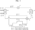
- FIG. 1 is a system diagram of a refrigerating system of the refrigerating apparatus 20 according to the embodiment of the present invention.
- the refrigerating system includes a compressor 5, a four-way valve 6, a decompressor 7, a water heat exchanger 8, an air heat exchanger 2, and a blower 4.
- the compressor 5, the four-way valve 6, the decompressor 7, the water heat exchanger 8, the air heat exchanger 2, and the blower 4 form a refrigerating cycle unit.
- the compressor 5 is configured as a screw compressor, a scroll compressor, or the like and compresses a coolant gas.
- the four-way valve 6 switchably supplies a compressed coolant gas discharged from the compressor 5 to the air heat exchanger 2 or the water heat exchanger 8.
- the decompressor 7 is configured as an electronic expansion valve, a capillary tube, or the like and decompresses a coolant.
- the water heat exchanger 8 cools or heats water such as cool water or hot water circulated and supplied from an indoor unit or the like. Apparatus water pipes 10 are connected to the water heat exchanger 8.
- the air heat exchanger 2 exchanges heat between the coolant and the outside air supplied by the blower 4.
- a cooling mode of the refrigerating system will be described.
- a sold-line arrow illustrated in FIG. 1 indicates the flow of a coolant in a cooling mode.
- the high-temperature and high-pressure coolant gas discharged from the compressor 5 flows into the air heat exchanger 2 under the control of the four-way valve 6, condenses by exchanging heat with the outside air, and flows into the water heat exchanger 8 by being decompressed and expanded by the decompressor 7.
- water (cool water) circulated and supplied from an indoor unit (not illustrated) such as an air-conditioning unit and the decompressed coolant exchange heat, and the water is cooled and returned to the indoor unit to perform air-conditioning or the like.
- the coolant is evaporated by stealing heat from the water supplied to the water heat exchanger 8 and is taken into the inlet side of the compressor 5 via the four-way valve 6.
- the coolant is compressed by the compressor 5 again, whereby a refrigerating cycle is formed.
- a heating mode of the refrigerating system will be described.
- a broken-line arrow in FIG. 1 indicates the flow of a coolant in a heating mode.
- the high-temperature and high-pressure coolant gas discharged from the compressor 5 flows into the water heat exchanger 8 under the control of the four-way valve 6 and heats the water (hot water) circulated and supplied from the water heat exchanger while condensing itself.
- the coolant condensed by the water heat exchanger 8 flows into the air heat exchanger 2 after being decompressed and expanded by the decompressor 7 and is evaporated by exchanging heat with the outside air.
- the evaporated coolant is taken into the inlet side of the compressor 5 via the four-way valve 6.
- the coolant is compressed by the compressor 5 again whereby a refrigerating cycle is formed.
- the refrigerating system of the present embodiment further includes a coolant pipe or the like that connects these components.
- the air heat exchanger 2 is configured as a fin tube-type heat exchanger or the like so that the blower 4 blows air between fins to exchange heat between a coolant and the outside air.
- water is supplied to the water heat exchanger 8 of the present embodiment as a heating medium, brine may be used instead of water.
- FIG. 2 is an external perspective view of the refrigerating apparatus 20.
- FIG. 3 is a plan view illustrating a drawing state of local water pipes 12 connected to the apparatus water pipes 10.
- the refrigerating apparatus 20 has a housing 13 that accommodates the refrigerating cycle unit described in FIG. 1 .
- the housing 13 has an approximately rectangular parallelepiped shape and includes a top plate 14, a bottom base 9, and four frame members 15.
- the top plate 14 and the bottom base 9 have a rectangular shape, the frame members 15 are disposed in four corners of these members 14 and 9, and the top plate 14, the bottom base 9, and the frame members 15 are combined together to form the housing 13.
- openings 16 are formed in the four surfaces (a front surface 13A, left and right side surfaces 13B, and a back surface 13C) of the housing 13 are formed (only two openings 16 are illustrated in FIG. 2 ).
- the blower 4 is attached to the top plate 14 and a ventilation hole cover 17 is provided to surround the blower 4.
- the air heat exchanger 2 is provided over an entire surface of three surfaces (the left and right side surfaces 13B and the back surface 13C) excluding the front surface 13A (an obliquely right-bottom surface in FIG. 2 and a lower surface in FIG. 3 ) of the housing 13 and is exposed outside via the corresponding opening 16.
- an operation panel (not illustrated) is attached to the front surface 13A of the housing 13.
- a piping opening 18 is formed in the bottom base 9.
- FIG. 1 A machine room 3 in which a cycle device such as the compressor 5 and the like that form the refrigerating cycle unit described in FIG. 1 is formed in a space formed by the air heat exchanger 2 and the bottom base 9. Only the water heat exchanger 8 and the apparatus water pipes 10 provided in the machine room 3 are illustrated in FIGS. 2 and 3 .
- Each apparatus water pipes 10 have such a shape that the apparatus water pipe 10 extends in a horizontal direction from the water heat exchanger 8 and is bent toward the piping opening 18 formed in the bottom base 9.
- the local water pipes 12 are inserted from the piping opening 18 and are connected to the apparatus water pipes 10 by a housing-type pipe connector 11, respectively.
- a flange may be provided in each apparatus water pipe 10 and each local water pipe 12 and the flanges may be connected.
- the apparatus water pipes 10 and the local water pipes 12 are connected inside the housing 13 of the refrigerating apparatus 20, the apparatus water pipes 10 may protrude from the piping opening 18 and the apparatus water pipes 10 and the local water pipes 12 may be connected in a lower part of the housing 13 of the refrigerating apparatus 20.
- the local water pipes 12 connected to the apparatus water pipes 10 are drawn toward any one of the front, rear, left, and right sides of the refrigerating apparatus 20 on the lower side of the bottom base 9 of the refrigerating apparatus 20 on the basis of the position of the indoor unit (not illustrated) or the like.
- the local water pipes 12 are drawn in the front-rear direction and the left-right direction in FIG. 3 , the drawing direction may intersect these directions.
- the housing 13 has the bottom base 9 in which the water heat exchanger 8 is disposed and the piping opening 18 for passing the water pipes (the apparatus water pipes 10 and the local water pipes 12) connected to the water heat exchanger 8 is formed.
- the drawing direction of the local water pipe 12 is not particularly limited, the local water pipes 12 can be drawn in any direction of the 360-degree omnidirection of the front-rear direction and the left-right direction when seen from such a plan view as FIG. 3 . In this way, it is possible to reduce the drawing space of the local water pipe 12 and to save the installation space of the refrigerating apparatus 20.
- the air heat exchanger 2 is provided over an entire surface of the left and right side surfaces 13B and the back surface 13C. Since the local water pipes 12 are disposed in the lower part of the bottom base 9, the front surface of the front surface 13A can be used as a maintenance surface and the maintenance workability can be improved.
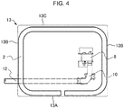
- the air heat exchanger 2 may be provided over a portion of the front surface 13A of the housing 13 and an entire surface of the left and right side surfaces 13B and the back surface 13C. Since the local water pipes 12 are disposed in the lower part of the bottom base 9, it is possible to improve heat exchange efficiency due to an increased heat-transfer area while securing a portion of the front surface 13A as a maintenance surface.
Landscapes
- Engineering & Computer Science (AREA)
- Mechanical Engineering (AREA)
- General Engineering & Computer Science (AREA)
- Chemical & Material Sciences (AREA)
- Combustion & Propulsion (AREA)
- Physics & Mathematics (AREA)
- Thermal Sciences (AREA)
- Life Sciences & Earth Sciences (AREA)
- Sustainable Development (AREA)
- Other Air-Conditioning Systems (AREA)
Abstract
Description
- The present invention relates to a refrigerating apparatus used as a heat source machine for air-conditioning or industrial purposes.
- A conventional refrigerating apparatus is configured such that a water pipe connected to a water heat exchanger faces any one of a front surface, left and right side surfaces, and a back surface of a housing so as to be connected to a local water pipe as disclosed in Japanese Patent Application Publication No.
2013-160445 - However, in the refrigerating apparatus disclosed in Japanese Patent Application Publication No.
2013-160445 - Therefore, an object of the present invention is to provide a refrigerating apparatus capable of reducing a space for drawing a local water pipe and saving a space for installation.
- In order to attain the object, a refrigerating apparatus according to an embodiment of the present invention includes: a refrigerating cycle unit including a compressor, an air heat exchanger, a blower, a decompressor, and a water heat exchanger; and/or a housing that accommodates the refrigerating cycle unit, wherein the housing has a bottom base in which the water heat exchanger is disposed and in which a piping opening for passing water pipes connected to the water heat exchanger is formed.
-
-
FIG. 1 is a system diagram of a refrigerating system of a refrigerating apparatus according to an embodiment of the present invention; -
FIG. 2 is a perspective view of the refrigerating apparatus according to the embodiment of the present invention; -
FIG. 3 is a plan view illustrating a drawing state of a local water pipe connected to a water pipe of a water heat exchanger; and -
FIG. 4 is a plan view illustrating a modification of an arrangement of the air heat exchanger. - Hereinafter, a refrigerating apparatus (an air-conditioning water cooling unit) 20 according to an embodiment of the present invention will be described. The refrigerating
apparatus 20 is used as a heat source machine for air-conditioning or industrial purposes. -
FIG. 1 is a system diagram of a refrigerating system of the refrigeratingapparatus 20 according to the embodiment of the present invention. - As illustrated in
FIG. 1 , the refrigerating system includes acompressor 5, a four-way valve 6, adecompressor 7, awater heat exchanger 8, anair heat exchanger 2, and ablower 4. Thecompressor 5, the four-way valve 6, thedecompressor 7, thewater heat exchanger 8, theair heat exchanger 2, and theblower 4 form a refrigerating cycle unit. - The
compressor 5 is configured as a screw compressor, a scroll compressor, or the like and compresses a coolant gas. The four-way valve 6 switchably supplies a compressed coolant gas discharged from thecompressor 5 to theair heat exchanger 2 or thewater heat exchanger 8. Thedecompressor 7 is configured as an electronic expansion valve, a capillary tube, or the like and decompresses a coolant. The water heat exchanger 8 cools or heats water such as cool water or hot water circulated and supplied from an indoor unit or the like.Apparatus water pipes 10 are connected to thewater heat exchanger 8. Theair heat exchanger 2 exchanges heat between the coolant and the outside air supplied by theblower 4. - A cooling mode of the refrigerating system will be described. A sold-line arrow illustrated in
FIG. 1 indicates the flow of a coolant in a cooling mode. - The high-temperature and high-pressure coolant gas discharged from the
compressor 5 flows into theair heat exchanger 2 under the control of the four-way valve 6, condenses by exchanging heat with the outside air, and flows into thewater heat exchanger 8 by being decompressed and expanded by thedecompressor 7. In thewater heat exchanger 8, water (cool water) circulated and supplied from an indoor unit (not illustrated) such as an air-conditioning unit and the decompressed coolant exchange heat, and the water is cooled and returned to the indoor unit to perform air-conditioning or the like. Moreover, the coolant is evaporated by stealing heat from the water supplied to thewater heat exchanger 8 and is taken into the inlet side of thecompressor 5 via the four-way valve 6. The coolant is compressed by thecompressor 5 again, whereby a refrigerating cycle is formed. - A heating mode of the refrigerating system will be described. A broken-line arrow in
FIG. 1 indicates the flow of a coolant in a heating mode. - The high-temperature and high-pressure coolant gas discharged from the
compressor 5 flows into thewater heat exchanger 8 under the control of the four-way valve 6 and heats the water (hot water) circulated and supplied from the water heat exchanger while condensing itself. The coolant condensed by thewater heat exchanger 8 flows into theair heat exchanger 2 after being decompressed and expanded by thedecompressor 7 and is evaporated by exchanging heat with the outside air. The evaporated coolant is taken into the inlet side of thecompressor 5 via the four-way valve 6. The coolant is compressed by thecompressor 5 again whereby a refrigerating cycle is formed. - In addition to the
compressor 5, the four-way valve 6, theair heat exchanger 2, thedecompressor 7, and thewater heat exchanger 8, the refrigerating system of the present embodiment further includes a coolant pipe or the like that connects these components. Moreover, theair heat exchanger 2 is configured as a fin tube-type heat exchanger or the like so that theblower 4 blows air between fins to exchange heat between a coolant and the outside air. Moreover, although water is supplied to thewater heat exchanger 8 of the present embodiment as a heating medium, brine may be used instead of water. - Next, the structure of the refrigerating
apparatus 20 according to the embodiment of the present invention will be described with reference toFIGS. 2 and3 . -
FIG. 2 is an external perspective view of the refrigeratingapparatus 20.FIG. 3 is a plan view illustrating a drawing state oflocal water pipes 12 connected to theapparatus water pipes 10. - As illustrated in
FIG. 2 , the refrigeratingapparatus 20 has ahousing 13 that accommodates the refrigerating cycle unit described inFIG. 1 . Thehousing 13 has an approximately rectangular parallelepiped shape and includes atop plate 14, abottom base 9, and fourframe members 15. Thetop plate 14 and thebottom base 9 have a rectangular shape, theframe members 15 are disposed in four corners of thesemembers top plate 14, thebottom base 9, and theframe members 15 are combined together to form thehousing 13. With thetop plate 14, thebottom base 9, and theframe members 15,openings 16 are formed in the four surfaces (afront surface 13A, left andright side surfaces 13B, and aback surface 13C) of thehousing 13 are formed (only twoopenings 16 are illustrated inFIG. 2 ). - The
blower 4 is attached to thetop plate 14 and aventilation hole cover 17 is provided to surround theblower 4. Theair heat exchanger 2 is provided over an entire surface of three surfaces (the left andright side surfaces 13B and theback surface 13C) excluding thefront surface 13A (an obliquely right-bottom surface inFIG. 2 and a lower surface inFIG. 3 ) of thehousing 13 and is exposed outside via thecorresponding opening 16. Moreover, an operation panel (not illustrated) is attached to thefront surface 13A of thehousing 13. Apiping opening 18 is formed in thebottom base 9. - A
machine room 3 in which a cycle device such as thecompressor 5 and the like that form the refrigerating cycle unit described inFIG. 1 is formed in a space formed by theair heat exchanger 2 and thebottom base 9. Only thewater heat exchanger 8 and theapparatus water pipes 10 provided in themachine room 3 are illustrated inFIGS. 2 and3 . Eachapparatus water pipes 10 have such a shape that theapparatus water pipe 10 extends in a horizontal direction from thewater heat exchanger 8 and is bent toward the piping opening 18 formed in thebottom base 9. - In a state in which the refrigerating
apparatus 20 is set on a local foundation, thelocal water pipes 12 are inserted from the piping opening 18 and are connected to theapparatus water pipes 10 by a housing-type pipe connector 11, respectively. Rather than using the housing-type pipe connector 11, a flange may be provided in eachapparatus water pipe 10 and eachlocal water pipe 12 and the flanges may be connected. Moreover, in the present embodiment, although theapparatus water pipes 10 and thelocal water pipes 12 are connected inside thehousing 13 of the refrigeratingapparatus 20, theapparatus water pipes 10 may protrude from the piping opening 18 and theapparatus water pipes 10 and thelocal water pipes 12 may be connected in a lower part of thehousing 13 of the refrigeratingapparatus 20. - As illustrated in
FIG. 3 , thelocal water pipes 12 connected to theapparatus water pipes 10 are drawn toward any one of the front, rear, left, and right sides of the refrigeratingapparatus 20 on the lower side of thebottom base 9 of the refrigeratingapparatus 20 on the basis of the position of the indoor unit (not illustrated) or the like. Although thelocal water pipes 12 are drawn in the front-rear direction and the left-right direction inFIG. 3 , the drawing direction may intersect these directions. - According to the refrigerating
apparatus 20, thehousing 13 has thebottom base 9 in which thewater heat exchanger 8 is disposed and the piping opening 18 for passing the water pipes (theapparatus water pipes 10 and the local water pipes 12) connected to thewater heat exchanger 8 is formed. According to this configuration, since thelocal water pipes 12 can be arranged in the lower part of thehousing 13, the drawing direction of thelocal water pipe 12 is not particularly limited, thelocal water pipes 12 can be drawn in any direction of the 360-degree omnidirection of the front-rear direction and the left-right direction when seen from such a plan view asFIG. 3 . In this way, it is possible to reduce the drawing space of thelocal water pipe 12 and to save the installation space of the refrigeratingapparatus 20. - The
air heat exchanger 2 is provided over an entire surface of the left andright side surfaces 13B and theback surface 13C. Since thelocal water pipes 12 are disposed in the lower part of thebottom base 9, the front surface of thefront surface 13A can be used as a maintenance surface and the maintenance workability can be improved. - While a preferred embodiment of the present invention has been described, the present invention is not limited to the above-described embodiment, and various changes in design can be made without departing from the spirit of the present invention.
- For example, as illustrated in
FIG. 4 , theair heat exchanger 2 may be provided over a portion of thefront surface 13A of thehousing 13 and an entire surface of the left and right side surfaces 13B and theback surface 13C. Since thelocal water pipes 12 are disposed in the lower part of thebottom base 9, it is possible to improve heat exchange efficiency due to an increased heat-transfer area while securing a portion of thefront surface 13A as a maintenance surface.
Claims (3)
- A refrigerating apparatus (20) comprising:a refrigerating cycle unit including a compressor (5), an air heat exchanger (2), a blower (4), a decompressor (7), and a water heat exchanger (8); anda housing (13) that accommodates the refrigerating cycle unit, whereinthe housing (13) has a bottom base (9) in which the water heat exchanger (8) is disposed and in which a piping opening (18) for passing water pipes connected to the water heat exchanger (8) is formed.
- The refrigerating apparatus according to claim 1, wherein
the housing (13) has a front surface as a maintenance surface, left and right side surfaces, and a back surface, and
the air heat exchanger (2) is provided over an entire surface of the left and right side surfaces and the back surface of the housing (13). - The refrigerating apparatus according to claim 1, wherein
the housing (13) has a front surface as a maintenance surface, left and right side surfaces, and a back surface, and
the air heat exchanger (2) is provided over a portion of the front surface and an entire surface of the left and right side surfaces and the back surface of the housing (13).
Applications Claiming Priority (1)
| Application Number | Priority Date | Filing Date | Title |
|---|---|---|---|
| JP2017121169A JP2019007642A (en) | 2017-06-21 | 2017-06-21 | Refrigeration device |
Publications (1)
| Publication Number | Publication Date |
|---|---|
| EP3418650A1 true EP3418650A1 (en) | 2018-12-26 |
Family
ID=62492484
Family Applications (1)
| Application Number | Title | Priority Date | Filing Date |
|---|---|---|---|
| EP18175137.1A Withdrawn EP3418650A1 (en) | 2017-06-21 | 2018-05-30 | Refrigerating apparatus |
Country Status (3)
| Country | Link |
|---|---|
| EP (1) | EP3418650A1 (en) |
| JP (1) | JP2019007642A (en) |
| CN (1) | CN109099521A (en) |
Citations (9)
| Publication number | Priority date | Publication date | Assignee | Title |
|---|---|---|---|---|
| JP2003279076A (en) * | 2002-03-20 | 2003-10-02 | Sanyo Electric Co Ltd | Outdoor unit of air-conditioner |
| JP2004132670A (en) * | 2002-10-15 | 2004-04-30 | Matsushita Electric Ind Co Ltd | Hot water storage heat pump water heater |
| EP1906107A1 (en) * | 2005-06-30 | 2008-04-02 | Toshiba Carrier Corporation | Heat pump hotwater supply device |
| JP2011133149A (en) * | 2009-12-24 | 2011-07-07 | Panasonic Corp | Heat pump type heat source device and heat pump water heater using the same |
| JP2011220569A (en) * | 2010-04-07 | 2011-11-04 | Toshiba Carrier Corp | Heat pump water heater |
| JP2012247186A (en) * | 2012-09-14 | 2012-12-13 | Panasonic Corp | Heat pump water heater |
| JP2013160445A (en) | 2012-02-06 | 2013-08-19 | Hitachi Appliances Inc | Heat exchange unit and heat exchange device |
| EP3009755A1 (en) * | 2013-06-14 | 2016-04-20 | Mitsubishi Electric Corporation | Outdoor unit for air conditioner and production method for outdoor unit for air conditioner |
| WO2017077648A1 (en) * | 2015-11-06 | 2017-05-11 | 三菱電機株式会社 | Outdoor unit |
Family Cites Families (3)
| Publication number | Priority date | Publication date | Assignee | Title |
|---|---|---|---|---|
| JP3807408B2 (en) * | 2004-03-31 | 2006-08-09 | ダイキン工業株式会社 | Heat exchanger |
| JP5388969B2 (en) * | 2010-08-23 | 2014-01-15 | 三菱電機株式会社 | Heat exchanger and air conditioner equipped with this heat exchanger |
| WO2016002023A1 (en) * | 2014-07-02 | 2016-01-07 | 三菱電機株式会社 | Heat source device and heat source system provided with heat source device |
-
2017
- 2017-06-21 JP JP2017121169A patent/JP2019007642A/en active Pending
-
2018
- 2018-05-28 CN CN201810525277.4A patent/CN109099521A/en active Pending
- 2018-05-30 EP EP18175137.1A patent/EP3418650A1/en not_active Withdrawn
Patent Citations (9)
| Publication number | Priority date | Publication date | Assignee | Title |
|---|---|---|---|---|
| JP2003279076A (en) * | 2002-03-20 | 2003-10-02 | Sanyo Electric Co Ltd | Outdoor unit of air-conditioner |
| JP2004132670A (en) * | 2002-10-15 | 2004-04-30 | Matsushita Electric Ind Co Ltd | Hot water storage heat pump water heater |
| EP1906107A1 (en) * | 2005-06-30 | 2008-04-02 | Toshiba Carrier Corporation | Heat pump hotwater supply device |
| JP2011133149A (en) * | 2009-12-24 | 2011-07-07 | Panasonic Corp | Heat pump type heat source device and heat pump water heater using the same |
| JP2011220569A (en) * | 2010-04-07 | 2011-11-04 | Toshiba Carrier Corp | Heat pump water heater |
| JP2013160445A (en) | 2012-02-06 | 2013-08-19 | Hitachi Appliances Inc | Heat exchange unit and heat exchange device |
| JP2012247186A (en) * | 2012-09-14 | 2012-12-13 | Panasonic Corp | Heat pump water heater |
| EP3009755A1 (en) * | 2013-06-14 | 2016-04-20 | Mitsubishi Electric Corporation | Outdoor unit for air conditioner and production method for outdoor unit for air conditioner |
| WO2017077648A1 (en) * | 2015-11-06 | 2017-05-11 | 三菱電機株式会社 | Outdoor unit |
Also Published As
| Publication number | Publication date |
|---|---|
| CN109099521A (en) | 2018-12-28 |
| JP2019007642A (en) | 2019-01-17 |
Similar Documents
| Publication | Publication Date | Title |
|---|---|---|
| CN105612390A (en) | Control box and air conditioner outdoor unit including the control box | |
| JP2013160445A (en) | Heat exchange unit and heat exchange device | |
| US20170138617A1 (en) | Air conditioner | |
| JP2003279076A (en) | Outdoor unit of air-conditioner | |
| JP6310077B2 (en) | Heat source system | |
| JPWO2014199484A1 (en) | Air conditioner | |
| WO2018055726A1 (en) | Ceiling suspension-type air conditioner | |
| CN207779203U (en) | Refrigeration cycle device | |
| JP6381799B2 (en) | Refrigeration cycle system | |
| JP7344130B2 (en) | Heat pump hot water heating system | |
| JP7137092B2 (en) | Heat exchanger | |
| KR101351857B1 (en) | a structure for arrangement of heat exchange on heater | |
| JP2019007642A (en) | Refrigeration device | |
| KR20180040370A (en) | Air conditioner | |
| JP7706278B2 (en) | Air Conditioning Equipment | |
| JP6758280B2 (en) | Air-conditioning indoor unit for computer room | |
| JP6486718B2 (en) | Heat exchanger | |
| CN220648474U (en) | Hydraulic module for air conditioner and air conditioner having same | |
| JP7609655B2 (en) | Air Conditioning Equipment | |
| KR20130028455A (en) | A heating apparatus without an outside-equipment | |
| JP6332991B2 (en) | Heat exchange unit for direct expansion cooler of refrigeration air conditioner | |
| CN207527884U (en) | Refrigeration cycle device | |
| JP4514504B2 (en) | Embedded ceiling air conditioner | |
| JP2010232212A (en) | fixing jig | |
| JP2022130225A (en) | Air conditioning system |
Legal Events
| Date | Code | Title | Description |
|---|---|---|---|
| STAA | Information on the status of an ep patent application or granted ep patent |
Free format text: STATUS: UNKNOWN |
|
| PUAI | Public reference made under article 153(3) epc to a published international application that has entered the european phase |
Free format text: ORIGINAL CODE: 0009012 |
|
| STAA | Information on the status of an ep patent application or granted ep patent |
Free format text: STATUS: REQUEST FOR EXAMINATION WAS MADE |
|
| 17P | Request for examination filed |
Effective date: 20180620 |
|
| AK | Designated contracting states |
Kind code of ref document: A1 Designated state(s): AL AT BE BG CH CY CZ DE DK EE ES FI FR GB GR HR HU IE IS IT LI LT LU LV MC MK MT NL NO PL PT RO RS SE SI SK SM TR |
|
| AX | Request for extension of the european patent |
Extension state: BA ME |
|
| STAA | Information on the status of an ep patent application or granted ep patent |
Free format text: STATUS: EXAMINATION IS IN PROGRESS |
|
| 17Q | First examination report despatched |
Effective date: 20190910 |
|
| GRAP | Despatch of communication of intention to grant a patent |
Free format text: ORIGINAL CODE: EPIDOSNIGR1 |
|
| STAA | Information on the status of an ep patent application or granted ep patent |
Free format text: STATUS: GRANT OF PATENT IS INTENDED |
|
| INTG | Intention to grant announced |
Effective date: 20200709 |
|
| STAA | Information on the status of an ep patent application or granted ep patent |
Free format text: STATUS: THE APPLICATION IS DEEMED TO BE WITHDRAWN |
|
| 18D | Application deemed to be withdrawn |
Effective date: 20201120 |