EP3418641A1 - Air conditioner - Google Patents
Air conditioner Download PDFInfo
- Publication number
- EP3418641A1 EP3418641A1 EP17752635.7A EP17752635A EP3418641A1 EP 3418641 A1 EP3418641 A1 EP 3418641A1 EP 17752635 A EP17752635 A EP 17752635A EP 3418641 A1 EP3418641 A1 EP 3418641A1
- Authority
- EP
- European Patent Office
- Prior art keywords
- support portion
- air conditioner
- disposed
- heat exchanger
- centrifugal fan
- Prior art date
- Legal status (The legal status is an assumption and is not a legal conclusion. Google has not performed a legal analysis and makes no representation as to the accuracy of the status listed.)
- Granted
Links
Images



Classifications
-
- F—MECHANICAL ENGINEERING; LIGHTING; HEATING; WEAPONS; BLASTING
- F04—POSITIVE - DISPLACEMENT MACHINES FOR LIQUIDS; PUMPS FOR LIQUIDS OR ELASTIC FLUIDS
- F04D—NON-POSITIVE-DISPLACEMENT PUMPS
- F04D29/00—Details, component parts, or accessories
- F04D29/40—Casings; Connections of working fluid
- F04D29/42—Casings; Connections of working fluid for radial or helico-centrifugal pumps
- F04D29/4206—Casings; Connections of working fluid for radial or helico-centrifugal pumps especially adapted for elastic fluid pumps
- F04D29/4226—Fan casings
-
- F—MECHANICAL ENGINEERING; LIGHTING; HEATING; WEAPONS; BLASTING
- F24—HEATING; RANGES; VENTILATING
- F24F—AIR-CONDITIONING; AIR-HUMIDIFICATION; VENTILATION; USE OF AIR CURRENTS FOR SCREENING
- F24F1/00—Room units for air-conditioning, e.g. separate or self-contained units or units receiving primary air from a central station
- F24F1/0007—Indoor units, e.g. fan coil units
- F24F1/0018—Indoor units, e.g. fan coil units characterised by fans
- F24F1/0022—Centrifugal or radial fans
-
- F—MECHANICAL ENGINEERING; LIGHTING; HEATING; WEAPONS; BLASTING
- F04—POSITIVE - DISPLACEMENT MACHINES FOR LIQUIDS; PUMPS FOR LIQUIDS OR ELASTIC FLUIDS
- F04D—NON-POSITIVE-DISPLACEMENT PUMPS
- F04D29/00—Details, component parts, or accessories
-
- F—MECHANICAL ENGINEERING; LIGHTING; HEATING; WEAPONS; BLASTING
- F04—POSITIVE - DISPLACEMENT MACHINES FOR LIQUIDS; PUMPS FOR LIQUIDS OR ELASTIC FLUIDS
- F04D—NON-POSITIVE-DISPLACEMENT PUMPS
- F04D29/00—Details, component parts, or accessories
- F04D29/58—Cooling; Heating; Diminishing heat transfer
- F04D29/582—Cooling; Heating; Diminishing heat transfer specially adapted for elastic fluid pumps
- F04D29/5826—Cooling at least part of the working fluid in a heat exchanger
-
- F—MECHANICAL ENGINEERING; LIGHTING; HEATING; WEAPONS; BLASTING
- F24—HEATING; RANGES; VENTILATING
- F24F—AIR-CONDITIONING; AIR-HUMIDIFICATION; VENTILATION; USE OF AIR CURRENTS FOR SCREENING
- F24F1/00—Room units for air-conditioning, e.g. separate or self-contained units or units receiving primary air from a central station
- F24F1/0007—Indoor units, e.g. fan coil units
- F24F1/0011—Indoor units, e.g. fan coil units characterised by air outlets
-
- F—MECHANICAL ENGINEERING; LIGHTING; HEATING; WEAPONS; BLASTING
- F24—HEATING; RANGES; VENTILATING
- F24F—AIR-CONDITIONING; AIR-HUMIDIFICATION; VENTILATION; USE OF AIR CURRENTS FOR SCREENING
- F24F1/00—Room units for air-conditioning, e.g. separate or self-contained units or units receiving primary air from a central station
- F24F1/0007—Indoor units, e.g. fan coil units
- F24F1/0059—Indoor units, e.g. fan coil units characterised by heat exchangers
- F24F1/0063—Indoor units, e.g. fan coil units characterised by heat exchangers by the mounting or arrangement of the heat exchangers
-
- F—MECHANICAL ENGINEERING; LIGHTING; HEATING; WEAPONS; BLASTING
- F24—HEATING; RANGES; VENTILATING
- F24F—AIR-CONDITIONING; AIR-HUMIDIFICATION; VENTILATION; USE OF AIR CURRENTS FOR SCREENING
- F24F13/00—Details common to, or for air-conditioning, air-humidification, ventilation or use of air currents for screening
- F24F13/20—Casings or covers
-
- F—MECHANICAL ENGINEERING; LIGHTING; HEATING; WEAPONS; BLASTING
- F24—HEATING; RANGES; VENTILATING
- F24F—AIR-CONDITIONING; AIR-HUMIDIFICATION; VENTILATION; USE OF AIR CURRENTS FOR SCREENING
- F24F13/00—Details common to, or for air-conditioning, air-humidification, ventilation or use of air currents for screening
- F24F13/30—Arrangement or mounting of heat-exchangers
-
- F—MECHANICAL ENGINEERING; LIGHTING; HEATING; WEAPONS; BLASTING
- F24—HEATING; RANGES; VENTILATING
- F24F—AIR-CONDITIONING; AIR-HUMIDIFICATION; VENTILATION; USE OF AIR CURRENTS FOR SCREENING
- F24F1/00—Room units for air-conditioning, e.g. separate or self-contained units or units receiving primary air from a central station
- F24F1/0007—Indoor units, e.g. fan coil units
- F24F1/0043—Indoor units, e.g. fan coil units characterised by mounting arrangements
- F24F1/0047—Indoor units, e.g. fan coil units characterised by mounting arrangements mounted in the ceiling or at the ceiling
-
- F—MECHANICAL ENGINEERING; LIGHTING; HEATING; WEAPONS; BLASTING
- F24—HEATING; RANGES; VENTILATING
- F24F—AIR-CONDITIONING; AIR-HUMIDIFICATION; VENTILATION; USE OF AIR CURRENTS FOR SCREENING
- F24F1/00—Room units for air-conditioning, e.g. separate or self-contained units or units receiving primary air from a central station
- F24F1/0007—Indoor units, e.g. fan coil units
- F24F1/0059—Indoor units, e.g. fan coil units characterised by heat exchangers
- F24F1/0067—Indoor units, e.g. fan coil units characterised by heat exchangers by the shape of the heat exchangers or of parts thereof, e.g. of their fins
Definitions
- the present invention relates to the field of refrigeration, and more particularly to an air conditioner.
- the blade diameter of a centrifugal fan used in an indoor unit of an air conditioner is small. During the rotation of the centrifugal fan, the centrifugal fan shakes slightly, and there is no situation where the centrifugal fan hits other components. However, the centrifugal fan with small-diameter blades will affect the air volume and performance of the air conditioner.
- a large-diameter centrifugal fan is required.
- the centrifugal fan 20' is driven and fixed by a motor in the prior art.
- a distance H provided between a lower surface of the centrifugal fan 20' and an evaporator 30' is greater than or equal to 8mm.
- the centrifugal fan Because the centrifugal fan is large in diameter, the centrifugal fan will have a large amount of shaking. Meanwhile, under the action of gravity, the centrifugal fan will have a tendency of downward deformation, and then the centrifugal fan will hit the other components.
- Some embodiments of the present invention is mainly directed to an air conditioner, intended to solve the problem in the prior art that a large-diameter centrifugal fan cannot operate stably.
- an exemplary embodiment provides an air conditioner, including: a housing having an air inlet and an air outlet; a centrifugal fan rotatably disposed in the housing, the centrifugal fan including a plate portion and blades disposed on the plate portion; a heat exchanger, the heat exchanger being disposed in the housing; and a slidable support portion disposed in the housing to support the centrifugal fan.
- an axis of the centrifugal fan extends along a vertical direction, and the heat exchanger is disposed on a circumferential inner side of the blades.
- the slidable support portion is disposed between top of the heat exchanger and the plate portion so that the heat exchanger supports the centrifugal fan.
- the slidable support portion includes a first support portion and a second support portion, the first support portion is disposed on the heat exchanger, and the second support portion is disposed on the plate portion and moves synchronously with the plate portion.
- the slidable support portion also includes multiple rolling portions disposed on the first support portion, and the second support portion is in contact with the rolling portions.
- multiple receiving holes are provided on the first support portion, and the multiple rolling portions are mounted in the multiple receiving holes in one-to-one correspondence.
- the first support portion is of an annular structure, and the multiple receiving holes are arranged along a circumferential direction of the first support portion.
- the second support portion is provided with at least one annular track fitting the multiple rolling portions.
- the multiple rolling portions are arranged on the first support portion in multiple turns, and there are multiple annular tracks adapting to the multiple turns.
- the slidable support portion also includes a connecting piece, and the first support portion is connected to the heat exchanger through the connecting piece.
- the connecting piece includes a frame and a notch provided on the frame, and the frame is sleeved outside the heat exchanger and is connected to the first support portion through a fastener.
- the heat exchanger is annular.
- the slidable support portion includes a first support portion and a second support portion, the first support portion is disposed on the housing, and the second support portion is disposed on the plate portion and moves synchronously with the plate portion.
- the air inlet is provided at a lower part of the housing.
- the air outlet is provided on a circumferential side wall of the housing.
- a centrifugal fan is rotatably disposed in a housing of an air conditioner, and the centrifugal fan includes a plate portion and blades disposed on the plate portion.
- the air conditioner works, air enters an air inlet of the housing and then exits from an air outlet of the housing due to the effect of the centrifugal fan.
- a heat exchanger is also disposed in the housing of the air conditioner. The heat exchanger can play a role of heat exchange so that the temperature of the air passing through the heat exchanger changes.
- a slidable support portion is also disposed in the housing of the air conditioner to support the centrifugal fan.
- the drawings include the following reference signs: 20', centrifugal fan; 30', evaporator; 10, housing; 11, air inlet; 12, air outlet; 20, centrifugal fan; 21, plate portion; 22, blade; 30, heat exchanger; 40, slidable support portion; 41, first support portion; 42, second support portion; 43, rolling portion; 44, connecting piece.
- an air conditioner in the present embodiment includes a housing 10, a centrifugal fan 20, a heat exchanger 30, and a slidable support portion 40, wherein the housing 10 has an air inlet 11 and an air outlet 12; the centrifugal fan 20 is rotatably disposed in the housing 10, and the centrifugal fan 20 includes a plate portion 21 and blades 22 disposed on the plate portion 21; the heat exchanger 30 is disposed on a circumferential inner side of the blades 22; and the slidable support portion 40 is disposed between top of the heat exchanger 30 and the plate portion 21 so that the heat exchanger 30 supports the centrifugal fan 20.
- the centrifugal fan 20 is rotatably disposed in the housing 10 of an air conditioner, and the centrifugal fan 20 includes the plate portion 21 and the blades 22 disposed on the plate portion 21.
- the heat exchanger 30 is also disposed in the housing 10 of the air conditioner. The heat exchanger 30 can play a role of heat exchange so that the temperature of the air passing through the heat exchanger 30 changes.
- the slidable support portion 40 is also disposed in the housing 10 of the air conditioner to support the centrifugal fan 20.
- the technical solution of the present embodiment effectively solves the problem in the prior art that a large-diameter centrifugal fan cannot operate stably.
- the heat exchanger 30 and the housing 10 are connected through multiple metal sheets.
- the structure is simple, and easy to implement.
- the centrifugal fan 20 is driven by a motor, and the power of the motor is input from the center of the plate portion 21.
- an axis of the centrifugal fan 20 extends along a vertical direction, and the heat exchanger 30 is disposed on a circumferential inner side of the blades 22.
- the structure is simple and enables air entering the air conditioner to be more uniform in heat exchange.
- the slidable support portion 40 is disposed between top of the heat exchanger 30 and the plate portion 21 so that the heat exchanger 30 supports the centrifugal fan 20.
- the structure is simple, and easy to implement.
- the structure uses the heat exchanger 30 as a part of a support structure, which makes the structure of the air conditioner more compact, reduces the volume of a product, and enhances the appearance of the product.
- the slidable support portion 40 includes a first support portion 41 and a second support portion 42, the first support portion 41 is disposed on the heat exchanger 30, and the second support portion 42 is disposed on the plate portion 21 and moves synchronously with the plate portion 21.
- the structure enables the relative movement between the first support portion 41 and the second support portion 42 so as to ensure the normal operation of the air conditioner.
- the centrifugal fan 20 has a tendency of downward deformation when the air conditioner works, so the second support portion 42 on the plate portion 21 will also have a tendency of downward deformation.
- the heat exchanger 30 has a first support portion 41 that can fit the second support portion 42 so as to play a supporting role for the second support portion 42, that is, a supporting role for the centrifugal fan 20, thereby further enabling the large-diameter centrifugal fan 20 to operate stably and reliably.
- multiple rolling portions 43 are mounted on the first support portion 41, and the second support portion 42 is in contact with the rolling portions 43.
- the structure is simple, and rolling friction is generated between the first support portion 41 and the second support portion 42 by providing the rolling portions 43. Since the rolling friction force is small, the relative rotation between the first support portion 41 and the second support portion 42 is made easier, so that the abrasion between the first support portion 41 and the second support portion 42 is reduced, thereby ensuring the life of the air conditioner.
- the plate portion 21 and the second support portion 42 on the plate portion 21 press the multiple rolling portions 43 and the first support portion 41, thereby supporting the centrifugal fan 20.
- the rolling portions 43 are balls, and the structure is simple, and easy to implement.
- the rolling portions 43 may have other structures besides the balls. Specifically, the rolling portions may also be pulleys.
- the rolling portions 43 as the balls.
- multiple receiving holes are provided on the first support portion 41, and multiple the balls are mounted in the multiple receiving holes in one-to-one correspondence.
- the structure allows the balls to always be at a working position and enables the balls to normally roll.
- the first support portion 41 is of an annular structure, and the multiple receiving holes are arranged along a circumferential direction of the first support portion 41.
- the structure is simple, and easy to implement.
- the second support portion 42 is provided with at least one annular track fitting the balls.
- the structure allows the balls to always be at a working position and ensures relative rotation between the first support portion 41 and the second support portion 42. Moreover, because the balls fit the annular track on the second support portion 42, the structure of the entire air conditioner is more compact.
- the multiple balls are arranged on the first support portion 41 in multiple turns, and there are multiple annular tracks adapting to the multiple turns.
- the structure enables a better relative rotation between the first support portion 41 and the second support portion 42 while better supporting the centrifugal fan 20.
- the air conditioner also includes a connecting piece 44, and the first support portion 41 is connected to the heat exchanger 30 through the connecting piece 44.
- the structure is simple, and easy to implement.
- the connecting piece 44 includes a frame sleeved outside the heat exchanger 30 and a notch provided on the frame.
- the notch enables the frame to be easily sleeved on the heat exchanger 30.
- the connecting piece 44 may be connected to the first support portion 41 through a fastener, so that the first support portion 41 is fixed to the heat exchanger 30.
- the fastener may be a screw, and a screw hole adapting to the screw is provided around the notch of the frame and on the first support portion 41.
- the shape of the frame is not limited, and in the present embodiment, the frame is a rectangular frame.
- the heat exchanger 30 is annular.
- the structure can fully utilize the heat exchanger 30 for heat exchange.
- the heat exchanger 30 may be provided in multiple layers in a radial direction thereof depending on the need of refrigeration or heating. Air that needs heat exchange passes through the multi-layer heat exchanger, making the heat exchange of the air fuller.
- the slidable support portion 40 includes a first support portion 41 and a second support portion 42, the first support portion 41 is disposed on the housing 10, and the second support portion 42 is disposed on the plate portion 21 and moves synchronously with the plate portion 21.
- the structure is simple, and easy to implement.
- the air inlet 11 is provided at a lower part of the housing 10. Air enters the air conditioner from the air inlet 11 at a lower part of the housing 10, and is discharged from the air conditioner through the heat exchanger 30. Specifically, the center position of the air inlet 11 is located on a rotation axis of the centrifugal fan 20. In this way, the air enters from the center of the centrifugal fan 20, and the structure ensures that the inlet air volume, the outlet air volume and the outlet air temperature are more uniform.
- the air outlet 12 is provided on a circumferential side wall of the housing 10.
- the structure makes full use of the space of the air conditioner, so that the structure of the air conditioner is compact.
- the air outlet 12 is annular. In this way, the air conditioner may achieve a 360-degree air output, and the air conditioner ensures that the temperature in the indoor area is uniformly increased or decreased.
Landscapes
- Engineering & Computer Science (AREA)
- Mechanical Engineering (AREA)
- General Engineering & Computer Science (AREA)
- Chemical & Material Sciences (AREA)
- Combustion & Propulsion (AREA)
- Physics & Mathematics (AREA)
- Thermal Sciences (AREA)
- Air-Conditioning Room Units, And Self-Contained Units In General (AREA)
Abstract
Description
- The present invention relates to the field of refrigeration, and more particularly to an air conditioner.
- At present, the blade diameter of a centrifugal fan used in an indoor unit of an air conditioner is small. During the rotation of the centrifugal fan, the centrifugal fan shakes slightly, and there is no situation where the centrifugal fan hits other components. However, the centrifugal fan with small-diameter blades will affect the air volume and performance of the air conditioner.
- With the improvement of performance requirements of people for air conditioners, the centrifugal fan with the small-diameter blades has been unable to meet the needs of people. Therefore, a large-diameter centrifugal fan is required. As shown in
Fig. 1 and Fig. 2 , for an indoor fan of a centrifugal fan 20' with large-diameter blades, the centrifugal fan 20' is driven and fixed by a motor in the prior art. As shown inFig. 2 , in order to avoid interference between the centrifugal fan and other components, a distance H provided between a lower surface of the centrifugal fan 20' and an evaporator 30' is greater than or equal to 8mm. Because the centrifugal fan is large in diameter, the centrifugal fan will have a large amount of shaking. Meanwhile, under the action of gravity, the centrifugal fan will have a tendency of downward deformation, and then the centrifugal fan will hit the other components. - Some embodiments of the present invention is mainly directed to an air conditioner, intended to solve the problem in the prior art that a large-diameter centrifugal fan cannot operate stably.
- To this end, an exemplary embodiment provides an air conditioner, including: a housing having an air inlet and an air outlet; a centrifugal fan rotatably disposed in the housing, the centrifugal fan including a plate portion and blades disposed on the plate portion; a heat exchanger, the heat exchanger being disposed in the housing; and a slidable support portion disposed in the housing to support the centrifugal fan.
- In an exemplary embodiment, an axis of the centrifugal fan extends along a vertical direction, and the heat exchanger is disposed on a circumferential inner side of the blades.
- In an exemplary embodiment, the slidable support portion is disposed between top of the heat exchanger and the plate portion so that the heat exchanger supports the centrifugal fan.
- In an exemplary embodiment, the slidable support portion includes a first support portion and a second support portion, the first support portion is disposed on the heat exchanger, and the second support portion is disposed on the plate portion and moves synchronously with the plate portion.
- In an exemplary embodiment, the slidable support portion also includes multiple rolling portions disposed on the first support portion, and the second support portion is in contact with the rolling portions.
- In an exemplary embodiment, multiple receiving holes are provided on the first support portion, and the multiple rolling portions are mounted in the multiple receiving holes in one-to-one correspondence.
- In an exemplary embodiment, the first support portion is of an annular structure, and the multiple receiving holes are arranged along a circumferential direction of the first support portion.
- In an exemplary embodiment, the second support portion is provided with at least one annular track fitting the multiple rolling portions.
- In an exemplary embodiment, the multiple rolling portions are arranged on the first support portion in multiple turns, and there are multiple annular tracks adapting to the multiple turns.
- In an exemplary embodiment, the slidable support portion also includes a connecting piece, and the first support portion is connected to the heat exchanger through the connecting piece.
- In an exemplary embodiment, the connecting piece includes a frame and a notch provided on the frame, and the frame is sleeved outside the heat exchanger and is connected to the first support portion through a fastener.
- In an exemplary embodiment, the heat exchanger is annular.
- In an exemplary embodiment, the slidable support portion includes a first support portion and a second support portion, the first support portion is disposed on the housing, and the second support portion is disposed on the plate portion and moves synchronously with the plate portion.
- In an exemplary embodiment, the air inlet is provided at a lower part of the housing.
- In an exemplary embodiment, the air outlet is provided on a circumferential side wall of the housing.
- By applying the technical solution of some embodiments of the present invention, a centrifugal fan is rotatably disposed in a housing of an air conditioner, and the centrifugal fan includes a plate portion and blades disposed on the plate portion. When the air conditioner works, air enters an air inlet of the housing and then exits from an air outlet of the housing due to the effect of the centrifugal fan. In some embodiments of the present invention, a heat exchanger is also disposed in the housing of the air conditioner. The heat exchanger can play a role of heat exchange so that the temperature of the air passing through the heat exchanger changes. In addition, a slidable support portion is also disposed in the housing of the air conditioner to support the centrifugal fan. In this way, even if the diameter of the centrifugal fan in some embodiments of the present invention is large, due to the supporting action of the slidable support portion, the shaking of the centrifugal fan can be reduced, and the centrifugal fan will not have a tendency of downward deformation due to gravity. Therefore, the technical solution of some embodiments of the present invention effectively solves the problem in the prior art that a large-diameter centrifugal fan cannot operate stably.
- The drawings of the description, forming a part of the present application, are used to provide a further understanding for the present invention. The schematic embodiments and illustrations of the present invention are used to explain the present invention, and do not form improper limits to the present invention. In the drawings:
-
Fig. 1 shows a structural schematic view of an air conditioner in the prior art; -
Fig. 2 shows an enlarged schematic view of A of the air conditioner inFig. 1 ; -
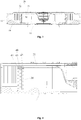
Fig. 3 shows a schematic view of a longitudinal section structure of an embodiment for an air conditioner according to the present invention; -
Fig. 4 shows a partial enlarged schematic view of the air conditioner inFig. 3 ; -
Fig. 5 shows an exploded schematic view of a partial structure of the air conditioner inFig. 3 ; -
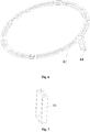
Fig. 6 shows a schematic view of a fitting state between a first support part and a connecting piece of the air conditioner inFig. 3 ; -
Fig. 7 shows a structural schematic view of the connecting piece inFig. 6 ; -
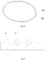
Fig. 8 shows a schematic view of a fitting state between a first support portion and a ball of the air conditioner inFig. 3 ; -
Fig. 9 shows a sectional schematic view of a fitting state between the first support portion and the ball inFig. 8 ; and -
Fig. 10 shows a structural schematic view of a centrifugal fan of the air conditioner inFig. 3 . - The drawings include the following reference signs:
20', centrifugal fan; 30', evaporator; 10, housing; 11, air inlet; 12, air outlet; 20, centrifugal fan; 21, plate portion; 22, blade; 30, heat exchanger; 40, slidable support portion; 41, first support portion; 42, second support portion; 43, rolling portion; 44, connecting piece. - It is important to note that embodiments in the present application and characteristics in the embodiments may be combined under the condition of no conflicts. The present invention will be illustrated hereinbelow with reference to the drawings and in conjunction with the embodiments in detail.
- As shown in
Fig. 3 and Fig. 4 , an air conditioner in the present embodiment includes ahousing 10, acentrifugal fan 20, aheat exchanger 30, and aslidable support portion 40, wherein thehousing 10 has anair inlet 11 and an air outlet 12; thecentrifugal fan 20 is rotatably disposed in thehousing 10, and thecentrifugal fan 20 includes aplate portion 21 andblades 22 disposed on theplate portion 21; theheat exchanger 30 is disposed on a circumferential inner side of theblades 22; and theslidable support portion 40 is disposed between top of theheat exchanger 30 and theplate portion 21 so that theheat exchanger 30 supports thecentrifugal fan 20. - By applying the technical solution of the present embodiment, the
centrifugal fan 20 is rotatably disposed in thehousing 10 of an air conditioner, and thecentrifugal fan 20 includes theplate portion 21 and theblades 22 disposed on theplate portion 21. When the air conditioner works, air enters theair inlet 11 of thehousing 10 and then exits from the air outlet 12 of thehousing 10 due to the effect of the centrifugal fan. In the present embodiment, theheat exchanger 30 is also disposed in thehousing 10 of the air conditioner. Theheat exchanger 30 can play a role of heat exchange so that the temperature of the air passing through theheat exchanger 30 changes. In addition, theslidable support portion 40 is also disposed in thehousing 10 of the air conditioner to support thecentrifugal fan 20. In this way, even if the diameter of thecentrifugal fan 20 in the present application is large, due to the supporting action of theslidable support portion 40, the shaking of thecentrifugal fan 20 can be reduced, and thecentrifugal fan 20 will not have a tendency of downward deformation due to gravity. Therefore, the technical solution of the present embodiment effectively solves the problem in the prior art that a large-diameter centrifugal fan cannot operate stably. - As shown in
Fig. 5 , theheat exchanger 30 and thehousing 10 are connected through multiple metal sheets. The structure is simple, and easy to implement. In the present embodiment, thecentrifugal fan 20 is driven by a motor, and the power of the motor is input from the center of theplate portion 21. - As shown in
Fig. 3 , in the present embodiment, an axis of thecentrifugal fan 20 extends along a vertical direction, and theheat exchanger 30 is disposed on a circumferential inner side of theblades 22. The structure is simple and enables air entering the air conditioner to be more uniform in heat exchange. - As shown in
Fig. 3 and Fig. 4 , in the present embodiment, theslidable support portion 40 is disposed between top of theheat exchanger 30 and theplate portion 21 so that theheat exchanger 30 supports thecentrifugal fan 20. The structure is simple, and easy to implement. The structure uses theheat exchanger 30 as a part of a support structure, which makes the structure of the air conditioner more compact, reduces the volume of a product, and enhances the appearance of the product. - As shown in
Fig. 4 , in the present embodiment, theslidable support portion 40 includes afirst support portion 41 and asecond support portion 42, thefirst support portion 41 is disposed on theheat exchanger 30, and thesecond support portion 42 is disposed on theplate portion 21 and moves synchronously with theplate portion 21. The structure enables the relative movement between thefirst support portion 41 and thesecond support portion 42 so as to ensure the normal operation of the air conditioner. Meanwhile, due to the action of gravity, thecentrifugal fan 20 has a tendency of downward deformation when the air conditioner works, so thesecond support portion 42 on theplate portion 21 will also have a tendency of downward deformation. By applying the technical solution of the present embodiment, theheat exchanger 30 has afirst support portion 41 that can fit thesecond support portion 42 so as to play a supporting role for thesecond support portion 42, that is, a supporting role for thecentrifugal fan 20, thereby further enabling the large-diametercentrifugal fan 20 to operate stably and reliably. - As shown in
Fig. 4 , in the present embodiment, multiple rollingportions 43 are mounted on thefirst support portion 41, and thesecond support portion 42 is in contact with the rollingportions 43. Firstly, the structure is simple, and rolling friction is generated between thefirst support portion 41 and thesecond support portion 42 by providing the rollingportions 43. Since the rolling friction force is small, the relative rotation between thefirst support portion 41 and thesecond support portion 42 is made easier, so that the abrasion between thefirst support portion 41 and thesecond support portion 42 is reduced, thereby ensuring the life of the air conditioner. Secondly, under the action of gravity, theplate portion 21 and thesecond support portion 42 on theplate portion 21 press the multiple rollingportions 43 and thefirst support portion 41, thereby supporting thecentrifugal fan 20. Preferably, the rollingportions 43 are balls, and the structure is simple, and easy to implement. Of course, those skilled in the art should know that the rollingportions 43 may have other structures besides the balls. Specifically, the rolling portions may also be pulleys. - The following describes the present embodiment with the rolling
portions 43 as the balls. As shown inFig. 8 and Fig. 9 , in the present embodiment, multiple receiving holes are provided on thefirst support portion 41, and multiple the balls are mounted in the multiple receiving holes in one-to-one correspondence. The structure allows the balls to always be at a working position and enables the balls to normally roll. - As shown in
Fig. 5 andFig. 8 , in the present embodiment, thefirst support portion 41 is of an annular structure, and the multiple receiving holes are arranged along a circumferential direction of thefirst support portion 41. The structure is simple, and easy to implement. - As shown in
Fig. 5 andFig. 10 , in the present embodiment, thesecond support portion 42 is provided with at least one annular track fitting the balls. The structure allows the balls to always be at a working position and ensures relative rotation between thefirst support portion 41 and thesecond support portion 42. Moreover, because the balls fit the annular track on thesecond support portion 42, the structure of the entire air conditioner is more compact. - As shown in
Fig. 8 to Fig. 10 , in the present embodiment, the multiple balls are arranged on thefirst support portion 41 in multiple turns, and there are multiple annular tracks adapting to the multiple turns. The structure enables a better relative rotation between thefirst support portion 41 and thesecond support portion 42 while better supporting thecentrifugal fan 20. - As shown in
Fig. 6 and Fig. 7 , in the present embodiment, the air conditioner also includes a connectingpiece 44, and thefirst support portion 41 is connected to theheat exchanger 30 through the connectingpiece 44. The structure is simple, and easy to implement. - As shown in
Fig. 6 and Fig. 7 , in the present embodiment, the connectingpiece 44 includes a frame sleeved outside theheat exchanger 30 and a notch provided on the frame. The notch enables the frame to be easily sleeved on theheat exchanger 30. When the frame is sleeved on theheat exchanger 30, the connectingpiece 44 may be connected to thefirst support portion 41 through a fastener, so that thefirst support portion 41 is fixed to theheat exchanger 30. Preferably, the fastener may be a screw, and a screw hole adapting to the screw is provided around the notch of the frame and on thefirst support portion 41. Of course, those skilled in the art should know that the shape of the frame is not limited, and in the present embodiment, the frame is a rectangular frame. - As shown in
Fig. 3 and Fig. 4 , in the present embodiment, theheat exchanger 30 is annular. The structure can fully utilize theheat exchanger 30 for heat exchange. Of course, theheat exchanger 30 may be provided in multiple layers in a radial direction thereof depending on the need of refrigeration or heating. Air that needs heat exchange passes through the multi-layer heat exchanger, making the heat exchange of the air fuller. - In an embodiment not shown in the figures, the
slidable support portion 40 includes afirst support portion 41 and asecond support portion 42, thefirst support portion 41 is disposed on thehousing 10, and thesecond support portion 42 is disposed on theplate portion 21 and moves synchronously with theplate portion 21. The structure is simple, and easy to implement. - As shown in
Fig. 3 , in the present embodiment, theair inlet 11 is provided at a lower part of thehousing 10. Air enters the air conditioner from theair inlet 11 at a lower part of thehousing 10, and is discharged from the air conditioner through theheat exchanger 30. Specifically, the center position of theair inlet 11 is located on a rotation axis of thecentrifugal fan 20. In this way, the air enters from the center of thecentrifugal fan 20, and the structure ensures that the inlet air volume, the outlet air volume and the outlet air temperature are more uniform. - As shown in
Fig. 3 , in the present embodiment, the air outlet 12 is provided on a circumferential side wall of thehousing 10. The structure makes full use of the space of the air conditioner, so that the structure of the air conditioner is compact. Specifically, the air outlet 12 is annular. In this way, the air conditioner may achieve a 360-degree air output, and the air conditioner ensures that the temperature in the indoor area is uniformly increased or decreased. - The above is only the preferable embodiments of the present invention, and not intended to limit the present invention. As will occur to those skilled in the art, the present invention is susceptible to various modifications and changes. Any modifications, equivalent replacements, improvements and the like made within the spirit and principle of the present invention shall fall within the scope of protection of the present invention.
Claims (15)
- An air conditioner, comprising:a housing (10), having an air inlet (11) and an air outlet (12);a centrifugal fan (20) rotatably disposed in the housing (10), the centrifugal fan (20) comprising a plate portion (21) and blades (22) disposed on the plate portion (21);a heat exchanger (30), the heat exchanger (30) being disposed in the housing (10); anda slidable support portion (40) disposed in the housing (10) to support the centrifugal fan (20).
- The air conditioner as claimed in claim 1, wherein an axis of the centrifugal fan (20) extends along a vertical direction, and the heat exchanger (30) is disposed on a circumferential inner side of the blades (22).
- The air conditioner as claimed in claim 2, wherein the slidable support portion (40) is disposed between top of the heat exchanger (30) and the plate portion (21) so that the heat exchanger (30) supports the centrifugal fan (20).
- The air conditioner as claimed in claim 3, wherein the slidable support portion (40) comprises a first support portion (41) and a second support portion (42), the first support portion (41) is disposed on the heat exchanger (30), and the second support portion (42) is disposed on the plate portion (21) and moves synchronously with the plate portion (21).
- The air conditioner as claimed in claim 4, wherein the slidable support portion (40) further comprises multiple rolling portions (43) disposed on the first support portion (41), and the second support portion (42) is in contact with the rolling portions (43).
- The air conditioner as claimed in claim 5, wherein multiple receiving holes are provided on the first support portion (41), and the multiple rolling portions (43) is mounted in the multiple receiving holes in one-to-one correspondence.
- The air conditioner as claimed in claim 6, wherein the first support portion (41) is of an annular structure, and the multiple receiving holes are arranged along a circumferential direction of the first support portion (41).
- The air conditioner as claimed in claim 5, wherein the second support portion (42) is provided with at least one annular track fitting the multiple rolling portions (43).
- The air conditioner as claimed in claim 8, wherein the multiple rolling portions (43) are arranged on the first support portion (41) in multiple turns, and there are multiple annular tracks adapting to the multiple turns.
- The air conditioner as claimed in claim 4, wherein the slidable support portion (40) further comprises a connecting piece (44), and the first support portion (41) is connected to the heat exchanger (30) through the connecting piece (44).
- The air conditioner as claimed in claim 10, wherein the connecting piece (44) comprises a frame and a notch provided on the frame, and the frame is sleeved outside the heat exchanger (30) and is connected to the first support portion (41) through a fastener.
- The air conditioner as claimed in claim 1, wherein the heat exchanger (30) is annular.
- The air conditioner as claimed in claim 1, wherein the slidable support portion (40) comprises a first support portion (41) and a second support portion (42), the first support portion (41) is disposed on the housing (10), and the second support portion (42) is disposed on the plate portion (21) and moves synchronously with the plate portion (21).
- The air conditioner as claimed in any one of claims 1 to 13, wherein the air inlet (11) is provided at a lower part of the housing (10).
- The air conditioner as claimed in any one of claims 1 to 13, wherein the air outlet (12) is provided on a circumferential side wall of the housing (10).
Applications Claiming Priority (2)
| Application Number | Priority Date | Filing Date | Title |
|---|---|---|---|
| CN201610094899.7A CN105546661B (en) | 2016-02-19 | 2016-02-19 | Air conditioner |
| PCT/CN2017/072062 WO2017140203A1 (en) | 2016-02-19 | 2017-01-22 | Air conditioner |
Publications (3)
| Publication Number | Publication Date |
|---|---|
| EP3418641A1 true EP3418641A1 (en) | 2018-12-26 |
| EP3418641A4 EP3418641A4 (en) | 2019-10-23 |
| EP3418641B1 EP3418641B1 (en) | 2020-12-02 |
Family
ID=55826042
Family Applications (1)
| Application Number | Title | Priority Date | Filing Date |
|---|---|---|---|
| EP17752635.7A Active EP3418641B1 (en) | 2016-02-19 | 2017-01-22 | Air conditioner |
Country Status (4)
| Country | Link |
|---|---|
| US (1) | US10627132B2 (en) |
| EP (1) | EP3418641B1 (en) |
| CN (1) | CN105546661B (en) |
| WO (1) | WO2017140203A1 (en) |
Families Citing this family (21)
| Publication number | Priority date | Publication date | Assignee | Title |
|---|---|---|---|---|
| CN105546661B (en) | 2016-02-19 | 2018-11-06 | 珠海格力电器股份有限公司 | Air conditioner |
| CN106287953A (en) * | 2016-08-04 | 2017-01-04 | 珠海格力电器股份有限公司 | Air conditioner |
| JP7278710B2 (en) * | 2018-01-30 | 2023-05-22 | 三菱重工サーマルシステムズ株式会社 | Ceiling-mounted air conditioner |
| CN111442370B (en) * | 2019-01-17 | 2025-02-18 | 青岛海尔空调器有限总公司 | Ceiling air conditioner indoor unit |
| CN111442357B (en) * | 2019-01-17 | 2025-05-23 | 青岛海尔空调器有限总公司 | Suspended ceiling type air conditioner indoor unit |
| CN111442379B (en) * | 2019-01-17 | 2025-02-21 | 青岛海尔空调器有限总公司 | Laminar flow fan and ceiling mounted air conditioner indoor unit |
| CN111442364A (en) * | 2019-01-17 | 2020-07-24 | 青岛海尔空调器有限总公司 | Ceiling type air conditioner indoor unit |
| CN111442356A (en) * | 2019-01-17 | 2020-07-24 | 青岛海尔空调器有限总公司 | Ceiling type air conditioner indoor unit |
| CN111442371A (en) * | 2019-01-17 | 2020-07-24 | 青岛海尔空调器有限总公司 | Ceiling type air conditioner indoor unit |
| CN111442366A (en) * | 2019-01-17 | 2020-07-24 | 青岛海尔空调器有限总公司 | Ceiling type air conditioner indoor unit |
| CN111442363A (en) * | 2019-01-17 | 2020-07-24 | 青岛海尔空调器有限总公司 | Ceiling type air conditioner indoor unit |
| CN111442367A (en) * | 2019-01-17 | 2020-07-24 | 青岛海尔空调器有限总公司 | Ceiling type air conditioner indoor unit |
| CN111442362A (en) * | 2019-01-17 | 2020-07-24 | 青岛海尔空调器有限总公司 | Ceiling type air conditioner indoor unit |
| CN111442355A (en) * | 2019-01-17 | 2020-07-24 | 青岛海尔空调器有限总公司 | Ceiling type air conditioner indoor unit |
| CN111442368B (en) * | 2019-01-17 | 2025-02-21 | 青岛海尔空调器有限总公司 | Ceiling air conditioner indoor unit |
| CN110701676A (en) * | 2019-11-08 | 2020-01-17 | 海信(山东)空调有限公司 | Indoor unit of air conditioner |
| CN110726176A (en) * | 2019-11-08 | 2020-01-24 | 海信(山东)空调有限公司 | Indoor unit of air conditioner |
| CN110701678A (en) * | 2019-11-08 | 2020-01-17 | 海信(山东)空调有限公司 | Indoor unit of air conditioner |
| CN112539465A (en) * | 2020-09-28 | 2021-03-23 | Tcl空调器(中山)有限公司 | Air conditioner indoor unit and air conditioner |
| CN112728644B (en) * | 2020-12-28 | 2025-09-02 | 珠海格力电器股份有限公司 | Indoor unit and air conditioner |
| CN115899829B (en) * | 2022-12-05 | 2025-09-12 | 珠海格力电器股份有限公司 | Ceiling air conditioner |
Family Cites Families (31)
| Publication number | Priority date | Publication date | Assignee | Title |
|---|---|---|---|---|
| US4553404A (en) * | 1984-06-20 | 1985-11-19 | Whirlpool Corporation | Room air conditioner with high capacity fresh air circulation means |
| GB9423776D0 (en) * | 1994-11-25 | 1995-01-11 | Acg Deutschland Gmbh | Dashboard assembly |
| JPH09229409A (en) | 1996-02-22 | 1997-09-05 | Sanyo Electric Co Ltd | Air supply device and ceiling-embedded air conditioner using air supply device |
| AU708393B2 (en) * | 1997-06-17 | 1999-08-05 | Daikin Industries, Ltd. | Air conditioner |
| JPH1183060A (en) * | 1997-09-10 | 1999-03-26 | Mitsubishi Heavy Ind Ltd | Flush-with-ceiling type air conditioner |
| JP4151116B2 (en) * | 1997-12-10 | 2008-09-17 | ダイキン工業株式会社 | Air conditioner |
| JPH11190537A (en) | 1997-12-26 | 1999-07-13 | Daikin Ind Ltd | Air conditioner indoor unit |
| KR100299823B1 (en) | 1998-01-20 | 2001-11-22 | 윤종용 | Duct for window air conditioner |
| KR100445467B1 (en) * | 2001-04-20 | 2004-08-21 | 주식회사 엘지이아이 | Indoor unit for air conditioner |
| KR20040104772A (en) * | 2003-06-03 | 2004-12-13 | 삼성전자주식회사 | Turbofan and air conditioner with the same |
| ES2275405B1 (en) * | 2005-05-10 | 2008-05-01 | Universitat Politecnica De Catalunya | INTERIOR UNIT OF A CONDITIONING AIR EQUIPMENT. |
| WO2007058418A2 (en) * | 2005-11-21 | 2007-05-24 | Lg Electronics, Inc. | Air conditioning system |
| JP3998032B1 (en) * | 2006-04-18 | 2007-10-24 | ダイキン工業株式会社 | Air conditioner indoor unit |
| US8814639B1 (en) * | 2008-10-29 | 2014-08-26 | Climatecraft Technologies, Inc. | Fan system comprising fan array with surge control |
| US9395097B2 (en) * | 2011-10-17 | 2016-07-19 | Lennox Industries Inc. | Layout for an energy recovery ventilator system |
| JP5267690B2 (en) * | 2012-02-03 | 2013-08-21 | ダイキン工業株式会社 | Indoor unit |
| KR101918225B1 (en) * | 2012-02-15 | 2018-11-13 | 엘지전자 주식회사 | Indoor unit |
| JPWO2013160957A1 (en) * | 2012-04-26 | 2015-12-21 | 三菱電機株式会社 | Heat exchanger, indoor unit and refrigeration cycle apparatus |
| KR20140065026A (en) * | 2012-11-15 | 2014-05-29 | 엘지전자 주식회사 | Slim type air conditioner |
| CN104061632A (en) * | 2013-03-19 | 2014-09-24 | 海信科龙电器股份有限公司 | Outdoor unit of air conditioner |
| JP5668782B2 (en) * | 2013-04-30 | 2015-02-12 | ダイキン工業株式会社 | Decorative panel and air conditioner indoor unit equipped with the same |
| JP5644889B2 (en) * | 2013-04-30 | 2014-12-24 | ダイキン工業株式会社 | Air conditioner indoor unit |
| JP6341637B2 (en) * | 2013-06-14 | 2018-06-13 | 三菱電機株式会社 | Manufacturing method of centrifugal blower |
| EP3096092A4 (en) * | 2014-01-07 | 2017-10-25 | Mitsubishi Electric Corporation | Air-conditioning device |
| WO2015125673A1 (en) * | 2014-02-18 | 2015-08-27 | 東芝キヤリア株式会社 | Air conditioner |
| CN104632720A (en) * | 2014-12-30 | 2015-05-20 | 天津正本自控系统有限公司 | Centrifugal fan mounting structure for air purifier |
| CN204534832U (en) * | 2015-03-12 | 2015-08-05 | 广东美的暖通设备有限公司 | Indoor apparatus of air conditioner and air-conditioner |
| PL3270074T3 (en) * | 2015-03-26 | 2021-05-04 | Fujitsu General Limited | Ceiling-embedded air conditioner |
| JP6516095B2 (en) * | 2015-04-27 | 2019-05-22 | 株式会社富士通ゼネラル | Ceiling-mounted air conditioner |
| CN205402930U (en) * | 2016-02-19 | 2016-07-27 | 珠海格力电器股份有限公司 | air conditioner |
| CN105546661B (en) * | 2016-02-19 | 2018-11-06 | 珠海格力电器股份有限公司 | Air conditioner |
-
2016
- 2016-02-19 CN CN201610094899.7A patent/CN105546661B/en active Active
-
2017
- 2017-01-22 US US15/999,306 patent/US10627132B2/en active Active
- 2017-01-22 EP EP17752635.7A patent/EP3418641B1/en active Active
- 2017-01-22 WO PCT/CN2017/072062 patent/WO2017140203A1/en not_active Ceased
Also Published As
| Publication number | Publication date |
|---|---|
| CN105546661A (en) | 2016-05-04 |
| EP3418641A4 (en) | 2019-10-23 |
| EP3418641B1 (en) | 2020-12-02 |
| US20190041089A1 (en) | 2019-02-07 |
| US10627132B2 (en) | 2020-04-21 |
| WO2017140203A1 (en) | 2017-08-24 |
| CN105546661B (en) | 2018-11-06 |
Similar Documents
| Publication | Publication Date | Title |
|---|---|---|
| US10627132B2 (en) | Air conditioner | |
| US20160032942A1 (en) | Air conditioner | |
| US20190331350A1 (en) | Air conditioner | |
| CN106287973B (en) | Air-conditioning cabinet and air outlet control method of air-conditioning cabinet | |
| KR20110125454A (en) | Indoor unit of air conditioner | |
| CN105090073A (en) | Blower fan and air conditioner having the same | |
| CN207196677U (en) | Indoor apparatus of air conditioner and air conditioner | |
| CN206145829U (en) | Mobile air -conditioner | |
| CN206310688U (en) | The rotating mechanism and cabinet air-conditioner of outlet frame | |
| KR20180031526A (en) | Air conditioner | |
| CN107631360B (en) | Air conditioner indoor unit and air conditioner | |
| CN205641436U (en) | Wall -mounted air conditioner indoor unit | |
| KR20010102681A (en) | Indoor unit cross flow fan connection device for airconditioner | |
| CN106524456A (en) | Rotating mechanism for air outflow frame and cabinet air conditioner | |
| CN103574803B (en) | Air conditioner with water evaporation for cooling | |
| CN205402930U (en) | air conditioner | |
| CN208832637U (en) | A kind of movable type Air cooler | |
| CN206145833U (en) | Mobile air -conditioner | |
| CN112283909A (en) | Air conditioner control method and system and air conditioner | |
| CN106766066A (en) | The air-out control method of top air-out structure, cabinet air-conditioner, air-conditioner and air-conditioner | |
| CN219693452U (en) | Indoor unit of wall-mounted air conditioner | |
| CN207334944U (en) | Air conditioner room unit and air conditioner | |
| CN100541025C (en) | window air conditioner | |
| CN221858711U (en) | Mobile air conditioner | |
| CN221403432U (en) | Air guide device and air conditioner |
Legal Events
| Date | Code | Title | Description |
|---|---|---|---|
| STAA | Information on the status of an ep patent application or granted ep patent |
Free format text: STATUS: THE INTERNATIONAL PUBLICATION HAS BEEN MADE |
|
| PUAI | Public reference made under article 153(3) epc to a published international application that has entered the european phase |
Free format text: ORIGINAL CODE: 0009012 |
|
| STAA | Information on the status of an ep patent application or granted ep patent |
Free format text: STATUS: REQUEST FOR EXAMINATION WAS MADE |
|
| 17P | Request for examination filed |
Effective date: 20180830 |
|
| AK | Designated contracting states |
Kind code of ref document: A1 Designated state(s): AL AT BE BG CH CY CZ DE DK EE ES FI FR GB GR HR HU IE IS IT LI LT LU LV MC MK MT NL NO PL PT RO RS SE SI SK SM TR |
|
| AX | Request for extension of the european patent |
Extension state: BA ME |
|
| DAV | Request for validation of the european patent (deleted) | ||
| DAX | Request for extension of the european patent (deleted) | ||
| A4 | Supplementary search report drawn up and despatched |
Effective date: 20190923 |
|
| RIC1 | Information provided on ipc code assigned before grant |
Ipc: F04D 29/00 20060101ALI20190917BHEP Ipc: F24F 1/00 20190101AFI20190917BHEP Ipc: F24F 13/30 20060101ALI20190917BHEP Ipc: F24F 1/0022 20190101ALI20190917BHEP |
|
| REG | Reference to a national code |
Ref country code: DE Ref legal event code: R079 Ref document number: 602017028813 Country of ref document: DE Free format text: PREVIOUS MAIN CLASS: F24F0001000000 Ipc: F24F0001002200 |
|
| GRAP | Despatch of communication of intention to grant a patent |
Free format text: ORIGINAL CODE: EPIDOSNIGR1 |
|
| STAA | Information on the status of an ep patent application or granted ep patent |
Free format text: STATUS: GRANT OF PATENT IS INTENDED |
|
| RIC1 | Information provided on ipc code assigned before grant |
Ipc: F24F 1/0067 20190101ALN20200820BHEP Ipc: F04D 29/42 20060101ALI20200820BHEP Ipc: F04D 29/58 20060101ALI20200820BHEP Ipc: F24F 1/0047 20190101ALN20200820BHEP Ipc: F24F 1/0063 20190101ALI20200820BHEP Ipc: F24F 1/0022 20190101AFI20200820BHEP |
|
| INTG | Intention to grant announced |
Effective date: 20200909 |
|
| GRAS | Grant fee paid |
Free format text: ORIGINAL CODE: EPIDOSNIGR3 |
|
| GRAA | (expected) grant |
Free format text: ORIGINAL CODE: 0009210 |
|
| STAA | Information on the status of an ep patent application or granted ep patent |
Free format text: STATUS: THE PATENT HAS BEEN GRANTED |
|
| AK | Designated contracting states |
Kind code of ref document: B1 Designated state(s): AL AT BE BG CH CY CZ DE DK EE ES FI FR GB GR HR HU IE IS IT LI LT LU LV MC MK MT NL NO PL PT RO RS SE SI SK SM TR |
|
| REG | Reference to a national code |
Ref country code: GB Ref legal event code: FG4D |
|
| REG | Reference to a national code |
Ref country code: AT Ref legal event code: REF Ref document number: 1341349 Country of ref document: AT Kind code of ref document: T Effective date: 20201215 Ref country code: CH Ref legal event code: EP |
|
| REG | Reference to a national code |
Ref country code: IE Ref legal event code: FG4D |
|
| REG | Reference to a national code |
Ref country code: DE Ref legal event code: R096 Ref document number: 602017028813 Country of ref document: DE |
|
| PG25 | Lapsed in a contracting state [announced via postgrant information from national office to epo] |
Ref country code: RS Free format text: LAPSE BECAUSE OF FAILURE TO SUBMIT A TRANSLATION OF THE DESCRIPTION OR TO PAY THE FEE WITHIN THE PRESCRIBED TIME-LIMIT Effective date: 20201202 Ref country code: NO Free format text: LAPSE BECAUSE OF FAILURE TO SUBMIT A TRANSLATION OF THE DESCRIPTION OR TO PAY THE FEE WITHIN THE PRESCRIBED TIME-LIMIT Effective date: 20210302 Ref country code: FI Free format text: LAPSE BECAUSE OF FAILURE TO SUBMIT A TRANSLATION OF THE DESCRIPTION OR TO PAY THE FEE WITHIN THE PRESCRIBED TIME-LIMIT Effective date: 20201202 Ref country code: GR Free format text: LAPSE BECAUSE OF FAILURE TO SUBMIT A TRANSLATION OF THE DESCRIPTION OR TO PAY THE FEE WITHIN THE PRESCRIBED TIME-LIMIT Effective date: 20210303 |
|
| REG | Reference to a national code |
Ref country code: NL Ref legal event code: MP Effective date: 20201202 |
|
| REG | Reference to a national code |
Ref country code: AT Ref legal event code: MK05 Ref document number: 1341349 Country of ref document: AT Kind code of ref document: T Effective date: 20201202 |
|
| PG25 | Lapsed in a contracting state [announced via postgrant information from national office to epo] |
Ref country code: BG Free format text: LAPSE BECAUSE OF FAILURE TO SUBMIT A TRANSLATION OF THE DESCRIPTION OR TO PAY THE FEE WITHIN THE PRESCRIBED TIME-LIMIT Effective date: 20210302 Ref country code: LV Free format text: LAPSE BECAUSE OF FAILURE TO SUBMIT A TRANSLATION OF THE DESCRIPTION OR TO PAY THE FEE WITHIN THE PRESCRIBED TIME-LIMIT Effective date: 20201202 Ref country code: PL Free format text: LAPSE BECAUSE OF FAILURE TO SUBMIT A TRANSLATION OF THE DESCRIPTION OR TO PAY THE FEE WITHIN THE PRESCRIBED TIME-LIMIT Effective date: 20201202 Ref country code: SE Free format text: LAPSE BECAUSE OF FAILURE TO SUBMIT A TRANSLATION OF THE DESCRIPTION OR TO PAY THE FEE WITHIN THE PRESCRIBED TIME-LIMIT Effective date: 20201202 |
|
| PG25 | Lapsed in a contracting state [announced via postgrant information from national office to epo] |
Ref country code: HR Free format text: LAPSE BECAUSE OF FAILURE TO SUBMIT A TRANSLATION OF THE DESCRIPTION OR TO PAY THE FEE WITHIN THE PRESCRIBED TIME-LIMIT Effective date: 20201202 Ref country code: NL Free format text: LAPSE BECAUSE OF FAILURE TO SUBMIT A TRANSLATION OF THE DESCRIPTION OR TO PAY THE FEE WITHIN THE PRESCRIBED TIME-LIMIT Effective date: 20201202 |
|
| REG | Reference to a national code |
Ref country code: LT Ref legal event code: MG9D |
|
| PG25 | Lapsed in a contracting state [announced via postgrant information from national office to epo] |
Ref country code: SM Free format text: LAPSE BECAUSE OF FAILURE TO SUBMIT A TRANSLATION OF THE DESCRIPTION OR TO PAY THE FEE WITHIN THE PRESCRIBED TIME-LIMIT Effective date: 20201202 Ref country code: LT Free format text: LAPSE BECAUSE OF FAILURE TO SUBMIT A TRANSLATION OF THE DESCRIPTION OR TO PAY THE FEE WITHIN THE PRESCRIBED TIME-LIMIT Effective date: 20201202 Ref country code: EE Free format text: LAPSE BECAUSE OF FAILURE TO SUBMIT A TRANSLATION OF THE DESCRIPTION OR TO PAY THE FEE WITHIN THE PRESCRIBED TIME-LIMIT Effective date: 20201202 Ref country code: CZ Free format text: LAPSE BECAUSE OF FAILURE TO SUBMIT A TRANSLATION OF THE DESCRIPTION OR TO PAY THE FEE WITHIN THE PRESCRIBED TIME-LIMIT Effective date: 20201202 Ref country code: SK Free format text: LAPSE BECAUSE OF FAILURE TO SUBMIT A TRANSLATION OF THE DESCRIPTION OR TO PAY THE FEE WITHIN THE PRESCRIBED TIME-LIMIT Effective date: 20201202 Ref country code: PT Free format text: LAPSE BECAUSE OF FAILURE TO SUBMIT A TRANSLATION OF THE DESCRIPTION OR TO PAY THE FEE WITHIN THE PRESCRIBED TIME-LIMIT Effective date: 20210405 Ref country code: RO Free format text: LAPSE BECAUSE OF FAILURE TO SUBMIT A TRANSLATION OF THE DESCRIPTION OR TO PAY THE FEE WITHIN THE PRESCRIBED TIME-LIMIT Effective date: 20201202 |
|
| PG25 | Lapsed in a contracting state [announced via postgrant information from national office to epo] |
Ref country code: AT Free format text: LAPSE BECAUSE OF FAILURE TO SUBMIT A TRANSLATION OF THE DESCRIPTION OR TO PAY THE FEE WITHIN THE PRESCRIBED TIME-LIMIT Effective date: 20201202 |
|
| REG | Reference to a national code |
Ref country code: CH Ref legal event code: PL |
|
| REG | Reference to a national code |
Ref country code: DE Ref legal event code: R097 Ref document number: 602017028813 Country of ref document: DE |
|
| PG25 | Lapsed in a contracting state [announced via postgrant information from national office to epo] |
Ref country code: MC Free format text: LAPSE BECAUSE OF FAILURE TO SUBMIT A TRANSLATION OF THE DESCRIPTION OR TO PAY THE FEE WITHIN THE PRESCRIBED TIME-LIMIT Effective date: 20201202 Ref country code: IS Free format text: LAPSE BECAUSE OF FAILURE TO SUBMIT A TRANSLATION OF THE DESCRIPTION OR TO PAY THE FEE WITHIN THE PRESCRIBED TIME-LIMIT Effective date: 20210402 Ref country code: LU Free format text: LAPSE BECAUSE OF NON-PAYMENT OF DUE FEES Effective date: 20210122 |
|
| REG | Reference to a national code |
Ref country code: BE Ref legal event code: MM Effective date: 20210131 |
|
| PLBE | No opposition filed within time limit |
Free format text: ORIGINAL CODE: 0009261 |
|
| STAA | Information on the status of an ep patent application or granted ep patent |
Free format text: STATUS: NO OPPOSITION FILED WITHIN TIME LIMIT |
|
| PG25 | Lapsed in a contracting state [announced via postgrant information from national office to epo] |
Ref country code: IT Free format text: LAPSE BECAUSE OF FAILURE TO SUBMIT A TRANSLATION OF THE DESCRIPTION OR TO PAY THE FEE WITHIN THE PRESCRIBED TIME-LIMIT Effective date: 20201202 Ref country code: FR Free format text: LAPSE BECAUSE OF NON-PAYMENT OF DUE FEES Effective date: 20210202 Ref country code: AL Free format text: LAPSE BECAUSE OF FAILURE TO SUBMIT A TRANSLATION OF THE DESCRIPTION OR TO PAY THE FEE WITHIN THE PRESCRIBED TIME-LIMIT Effective date: 20201202 |
|
| 26N | No opposition filed |
Effective date: 20210903 |
|
| PG25 | Lapsed in a contracting state [announced via postgrant information from national office to epo] |
Ref country code: CH Free format text: LAPSE BECAUSE OF NON-PAYMENT OF DUE FEES Effective date: 20210131 Ref country code: DK Free format text: LAPSE BECAUSE OF FAILURE TO SUBMIT A TRANSLATION OF THE DESCRIPTION OR TO PAY THE FEE WITHIN THE PRESCRIBED TIME-LIMIT Effective date: 20201202 Ref country code: SI Free format text: LAPSE BECAUSE OF FAILURE TO SUBMIT A TRANSLATION OF THE DESCRIPTION OR TO PAY THE FEE WITHIN THE PRESCRIBED TIME-LIMIT Effective date: 20201202 Ref country code: LI Free format text: LAPSE BECAUSE OF NON-PAYMENT OF DUE FEES Effective date: 20210131 |
|
| PG25 | Lapsed in a contracting state [announced via postgrant information from national office to epo] |
Ref country code: IE Free format text: LAPSE BECAUSE OF NON-PAYMENT OF DUE FEES Effective date: 20210122 Ref country code: ES Free format text: LAPSE BECAUSE OF FAILURE TO SUBMIT A TRANSLATION OF THE DESCRIPTION OR TO PAY THE FEE WITHIN THE PRESCRIBED TIME-LIMIT Effective date: 20201202 |
|
| PG25 | Lapsed in a contracting state [announced via postgrant information from national office to epo] |
Ref country code: IS Free format text: LAPSE BECAUSE OF FAILURE TO SUBMIT A TRANSLATION OF THE DESCRIPTION OR TO PAY THE FEE WITHIN THE PRESCRIBED TIME-LIMIT Effective date: 20210402 |
|
| PG25 | Lapsed in a contracting state [announced via postgrant information from national office to epo] |
Ref country code: BE Free format text: LAPSE BECAUSE OF NON-PAYMENT OF DUE FEES Effective date: 20210131 |
|
| PG25 | Lapsed in a contracting state [announced via postgrant information from national office to epo] |
Ref country code: CY Free format text: LAPSE BECAUSE OF FAILURE TO SUBMIT A TRANSLATION OF THE DESCRIPTION OR TO PAY THE FEE WITHIN THE PRESCRIBED TIME-LIMIT Effective date: 20201202 |
|
| P01 | Opt-out of the competence of the unified patent court (upc) registered |
Effective date: 20230530 |
|
| PG25 | Lapsed in a contracting state [announced via postgrant information from national office to epo] |
Ref country code: HU Free format text: LAPSE BECAUSE OF FAILURE TO SUBMIT A TRANSLATION OF THE DESCRIPTION OR TO PAY THE FEE WITHIN THE PRESCRIBED TIME-LIMIT; INVALID AB INITIO Effective date: 20170122 |
|
| PG25 | Lapsed in a contracting state [announced via postgrant information from national office to epo] |
Ref country code: MK Free format text: LAPSE BECAUSE OF FAILURE TO SUBMIT A TRANSLATION OF THE DESCRIPTION OR TO PAY THE FEE WITHIN THE PRESCRIBED TIME-LIMIT Effective date: 20201202 |
|
| PG25 | Lapsed in a contracting state [announced via postgrant information from national office to epo] |
Ref country code: TR Free format text: LAPSE BECAUSE OF FAILURE TO SUBMIT A TRANSLATION OF THE DESCRIPTION OR TO PAY THE FEE WITHIN THE PRESCRIBED TIME-LIMIT Effective date: 20201202 |
|
| PG25 | Lapsed in a contracting state [announced via postgrant information from national office to epo] |
Ref country code: MT Free format text: LAPSE BECAUSE OF FAILURE TO SUBMIT A TRANSLATION OF THE DESCRIPTION OR TO PAY THE FEE WITHIN THE PRESCRIBED TIME-LIMIT Effective date: 20201202 |
|
| PGFP | Annual fee paid to national office [announced via postgrant information from national office to epo] |
Ref country code: GB Payment date: 20251215 Year of fee payment: 10 |
|
| PGFP | Annual fee paid to national office [announced via postgrant information from national office to epo] |
Ref country code: DE Payment date: 20260120 Year of fee payment: 10 |