EP3418612A1 - Structure for vane-type valve assembly - Google Patents
Structure for vane-type valve assembly Download PDFInfo
- Publication number
- EP3418612A1 EP3418612A1 EP18176800.3A EP18176800A EP3418612A1 EP 3418612 A1 EP3418612 A1 EP 3418612A1 EP 18176800 A EP18176800 A EP 18176800A EP 3418612 A1 EP3418612 A1 EP 3418612A1
- Authority
- EP
- European Patent Office
- Prior art keywords
- vane
- type valve
- plane
- valve assembly
- sealing plane
- Prior art date
- Legal status (The legal status is an assumption and is not a legal conclusion. Google has not performed a legal analysis and makes no representation as to the accuracy of the status listed.)
- Withdrawn
Links
Images


Classifications
-
- F—MECHANICAL ENGINEERING; LIGHTING; HEATING; WEAPONS; BLASTING
- F16—ENGINEERING ELEMENTS AND UNITS; GENERAL MEASURES FOR PRODUCING AND MAINTAINING EFFECTIVE FUNCTIONING OF MACHINES OR INSTALLATIONS; THERMAL INSULATION IN GENERAL
- F16K—VALVES; TAPS; COCKS; ACTUATING-FLOATS; DEVICES FOR VENTING OR AERATING
- F16K47/00—Means in valves for absorbing fluid energy
- F16K47/02—Means in valves for absorbing fluid energy for preventing water-hammer or noise
-
- F—MECHANICAL ENGINEERING; LIGHTING; HEATING; WEAPONS; BLASTING
- F04—POSITIVE - DISPLACEMENT MACHINES FOR LIQUIDS; PUMPS FOR LIQUIDS OR ELASTIC FLUIDS
- F04B—POSITIVE-DISPLACEMENT MACHINES FOR LIQUIDS; PUMPS
- F04B39/00—Component parts, details, or accessories, of pumps or pumping systems specially adapted for elastic fluids, not otherwise provided for in, or of interest apart from, groups F04B25/00 - F04B37/00
- F04B39/10—Adaptations or arrangements of distribution members
- F04B39/102—Adaptations or arrangements of distribution members the members being disc valves
-
- F—MECHANICAL ENGINEERING; LIGHTING; HEATING; WEAPONS; BLASTING
- F16—ENGINEERING ELEMENTS AND UNITS; GENERAL MEASURES FOR PRODUCING AND MAINTAINING EFFECTIVE FUNCTIONING OF MACHINES OR INSTALLATIONS; THERMAL INSULATION IN GENERAL
- F16K—VALVES; TAPS; COCKS; ACTUATING-FLOATS; DEVICES FOR VENTING OR AERATING
- F16K15/00—Check valves
- F16K15/14—Check valves with flexible valve members
- F16K15/16—Check valves with flexible valve members with tongue-shaped laminae
-
- F—MECHANICAL ENGINEERING; LIGHTING; HEATING; WEAPONS; BLASTING
- F04—POSITIVE - DISPLACEMENT MACHINES FOR LIQUIDS; PUMPS FOR LIQUIDS OR ELASTIC FLUIDS
- F04B—POSITIVE-DISPLACEMENT MACHINES FOR LIQUIDS; PUMPS
- F04B39/00—Component parts, details, or accessories, of pumps or pumping systems specially adapted for elastic fluids, not otherwise provided for in, or of interest apart from, groups F04B25/00 - F04B37/00
-
- F—MECHANICAL ENGINEERING; LIGHTING; HEATING; WEAPONS; BLASTING
- F16—ENGINEERING ELEMENTS AND UNITS; GENERAL MEASURES FOR PRODUCING AND MAINTAINING EFFECTIVE FUNCTIONING OF MACHINES OR INSTALLATIONS; THERMAL INSULATION IN GENERAL
- F16K—VALVES; TAPS; COCKS; ACTUATING-FLOATS; DEVICES FOR VENTING OR AERATING
- F16K15/00—Check valves
- F16K15/14—Check valves with flexible valve members
- F16K15/144—Check valves with flexible valve members the closure elements being fixed along all or a part of their periphery
-
- F—MECHANICAL ENGINEERING; LIGHTING; HEATING; WEAPONS; BLASTING
- F16—ENGINEERING ELEMENTS AND UNITS; GENERAL MEASURES FOR PRODUCING AND MAINTAINING EFFECTIVE FUNCTIONING OF MACHINES OR INSTALLATIONS; THERMAL INSULATION IN GENERAL
- F16K—VALVES; TAPS; COCKS; ACTUATING-FLOATS; DEVICES FOR VENTING OR AERATING
- F16K25/00—Details relating to contact between valve members and seats
Definitions
- the present invention refers to a structure for vane-type valve assembly in a positive displacement compressor and, more particularly, a structure comprising a base for seating and/or fixing the static end of a vane-type valve.
- the general objective of the present invention is to provide a simplified means capable of determining the initial state of the vane-type valve.
- positive displacement compressors also known as reciprocating compressors
- a fluid compression system that includes a control mechanism of the suction and discharge of working fluid.
- control mechanism basically consists of at least one suction valve and at least one discharge valve, which are able to clog/unclog the holes by which the working fluid enters or exits from the compression cylinder.
- suction valves or discharge valves may also be applied, in order to perform an analogous or equivalent function, in other components or mechanisms that make part of a positive displacement compressor.
- suction valves or discharge valves can be used in acoustic filters that make part of the positive displacement compressor.
- a vane-type valve is that formed by a flexible metal blade.
- a vane-type valve comprises a substantially static end, capable of being fixedly seated and/or fixed to a compressor structure, and a dynamic end, able to clog/unclog one or more holes through which the working fluid flows.
- Vane-type valves especially those used as suction valves or discharge valves in positive displacement compressors, are well known to those skilled in the art. Inclusively, an infinitude of models, normally variable in the geometrical aspect, of vane-type valves are pertaining to the current state of the art.
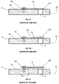
- FIG 1A shows, in a schematic and simplified manner, a trivial situation in which a vane-type valve B has an initial state, with respect to the hole C, normally closed.
- the vane-type valve B is fixed in a structure A , wherein its static end B1 is fixed in a plane A1 of the structure A by means of an pierced fixing element C , and its dynamic end B2 is seated on the hole C in a plane A2 of the structure A.
- the planes A1 and A2 of the structure A are horizontally equivalent, that is, they are defined on a same horizontal level.
- FIG. 1B The constructive possibility shown in Figure 1B involves a traditional structure A and a pre-tensioned vane-type valve B.
- Said pre-tensioned vane-type valve B normally obtained by means of a mechanical stamping process, is deformed so as to present a difference in level between the static end B1 and the dynamic end B2 .
- the static end B1 of the pre-tensioned vane-type valve B is fixed coplanar to the plane A1 of the structure A
- its dynamic end B2 is naturally spaced apart from the hole C and the plane A2 of the structure A.
- planes A1 and A2 of structure A are horizontally equivalent, that is, they are defined on a same horizontal level.
- a vane-type valve can act with the initial state normally opened if it is made in a pre-tensioned form.
- this constructive possibility normally, as it is based on plastic deformation, tends to shorten the service life of the valve, especially at the pre-tension point B3 defined by hydraulic press knock.
- FIG. 1C The constructive possibility shown in Figure 1C involves a traditional vane-type valve B and a modified structure A , which comprises a projection A3 between the planes A1 and A2. Therefore, it is observed that the planes A1 and A2 of the structure A are horizontally equivalent to each other, the projection A3 existing in a raised plane, however, coplanar to the planes A1 and A2.
- the entire extent of the vane-type valve B is disposed in a coplanar manner relative to the structure A , its dynamic end B2 is naturally spaced apart from the hole C and the plane A2 of the structure A. That is, a vane-type valve can act with the initial state normally opened if the structure on which it is mounted (usually, but not obligatorily, a metal valve plate) contains a vertical spacer.
- this constructive possibility presents severe sealing problems.
- an objective of the present invention to disclose an inventive core whose possibility of application achieves polymeric structures for vane-type valve assembly in a positive displacement compressor, such as the internal polymeric walls of an acoustic filter used in positive displacement compressors.
- vane-type valve assembly which comprises at least one seating plane (for the static end of a vane-type valve) and at least one sealing plane (for the dynamic end of a vane-type valve), wherein the seating plane and the sealing plane are angularly out of alignment from each other.
- the seating plane of the structure for vane-type valve assembly is defined at a first angle ⁇ and the sealing plane of the structure for vane-type valve assembly is defined at a second angle ⁇ .
- said vane-type valve 2 is a totally traditional valve, that is, which comprises a static end 21 (especially dedicated to fixing the valve in a fixed reference) and a dynamic end 22 (especially dedicated to movement as a function of external stimulus), said ends 21 and 22 being distally opposed.
- said vane-type valve 2 is maintained in an initial state normally opened due to the structure 1 , which basically comprises a seating plane 11 (especially adapted for receiving the static end 21 of the vane-type valve 2 ) and the sealing plane 12 (which, comprising the working hole 14 , is specially adapted for cooperation with the dynamic end 22 of the vane-type valve 2 ), wherein the seating plane 11 and the sealing plane 12 are angularly out of alignment from each other.
- the structure 1 which basically comprises a seating plane 11 (especially adapted for receiving the static end 21 of the vane-type valve 2 ) and the sealing plane 12 (which, comprising the working hole 14 , is specially adapted for cooperation with the dynamic end 22 of the vane-type valve 2 ), wherein the seating plane 11 and the sealing plane 12 are angularly out of alignment from each other.
- the seating plane 11 is defined at a first angle ⁇
- the sealing plane 12 is defined at a second angle ⁇ , wherein the angular difference between said planes is greater than 90° and less than 180°.
- the spacing between the dynamic end 22 of the vane-type valve 2 and the hole 14 of the structure 1 is defined directly by the angulation of the seating plane 11 , as shown in Figure 4 .
- the vane-type valve 2 is maintained in an initial state normally opened without the need for it to undergo physical-mechanical blemishes (as exemplified in Figure 1B ) and without the need for the structure itself to be made with a vertical spacer (as exemplified in Figure 1C ).
- the dynamic end 22 of the vane-type valve 2 when closed, has its deformation point defined near the transition point 13 of the structure 1.
- Said transition point 13 of the structure 1 comprises the bordering point between the seating plane 11 and the sealing plane 12 of the structure 1.
- the transition point 13 of the structure 1 (and, consequently, the vertical extensions of the planes 11 and 12 ) can be defined according to the general needs of the project such as the flexibility of the vane-type valve 2.
- the sealing plane 12 may be inclined with respect to the transition point 13 , that is, the transition point 13 and the sealing plane 12 are defined in different horizontal planes.
- the structure 1 can be manufactured in simplified form, after all, the seating plane 11 can be obtained, in a controlled manner, by mechanical stamping, machining or thermoforming process.
- the seating plane 11 may comprise a cavity with inclined bottom formed from the sealing plane 12.
- the structure 1 can receive on its sealing plane 12 , preferably around the hole 14 , a coplanar spacer element 4 , which is capable of optimizing the seal between the dynamic end 22 of the vane-type valve 2 and the hole 14 of the structure 1.
- the structure 1 - as explained above - may comprise a valve plate (see attached illustrations) or may comprise a wall of an acoustic filter (embodiment not particularly shown, but of easy intuition).
Landscapes
- Engineering & Computer Science (AREA)
- General Engineering & Computer Science (AREA)
- Mechanical Engineering (AREA)
- Compressor (AREA)
- Check Valves (AREA)
Abstract
Description
- The present invention refers to a structure for vane-type valve assembly in a positive displacement compressor and, more particularly, a structure comprising a base for seating and/or fixing the static end of a vane-type valve. The general objective of the present invention is to provide a simplified means capable of determining the initial state of the vane-type valve.
- As known to those skilled in the art, positive displacement compressors, also known as reciprocating compressors, typically include a fluid compression system that includes a control mechanism of the suction and discharge of working fluid. In general terms, such control mechanism basically consists of at least one suction valve and at least one discharge valve, which are able to clog/unclog the holes by which the working fluid enters or exits from the compression cylinder.
- Occasionally, suction valves or discharge valves may also be applied, in order to perform an analogous or equivalent function, in other components or mechanisms that make part of a positive displacement compressor. There are known, for example, technical solutions in which suction valves or discharge valves can be used in acoustic filters that make part of the positive displacement compressor.
- Although there are known different types of valves that can be used in positive displacement compressors, it is of particular interest, according to the core of the present invention, to consider the vane-type valves. Briefly, a vane-type valve is that formed by a flexible metal blade. In general terms, a vane-type valve comprises a substantially static end, capable of being fixedly seated and/or fixed to a compressor structure, and a dynamic end, able to clog/unclog one or more holes through which the working fluid flows.
- Vane-type valves, especially those used as suction valves or discharge valves in positive displacement compressors, are well known to those skilled in the art. Inclusively, an infinitude of models, normally variable in the geometrical aspect, of vane-type valves are pertaining to the current state of the art.
- In the vast majority of applications of vane-type valves in positive displacement compressors, it is common for the initial state of said valve, relative to its working hole, to be normally closed, that is, it is common that in the absence of factors and stimulus the valve is mounted in any structure so as to keep its working hole sealed/clogged.
-
Figure 1A shows, in a schematic and simplified manner, a trivial situation in which a vane-type valve B has an initial state, with respect to the hole C, normally closed. In this exemplification the vane-type valve B is fixed in a structure A, wherein its static end B1 is fixed in a plane A1 of the structure A by means of an pierced fixing element C, and its dynamic end B2 is seated on the hole C in a plane A2 of the structure A. It is observed that the planes A1 and A2 of the structure A are horizontally equivalent, that is, they are defined on a same horizontal level. - In addition, as is well known to those skilled in the art, it is known that certain applications may take advantage if a vane-type valve has its initial state normally opened. For example, it is mentioned cases in which it is desired to maintain a suction valve opened at the starting instant of the positive displacement compressor in order to decrease the starting torque of the compressor motor.
- In general terms, two constructive possibilities of obtaining a vane-type valve in the initial state opened are known. Such constructive possibilities are shown, in a schematic and simplified manner, in
Figures 1B and 1C . - The constructive possibility shown in
Figure 1B involves a traditional structure A and a pre-tensioned vane-type valve B. Said pre-tensioned vane-type valve B, normally obtained by means of a mechanical stamping process, is deformed so as to present a difference in level between the static end B1 and the dynamic end B2. Thus, although the static end B1 of the pre-tensioned vane-type valve B is fixed coplanar to the plane A1 of the structure A, its dynamic end B2 is naturally spaced apart from the hole C and the plane A2 of the structure A. It is observed that planes A1 and A2 of structure A are horizontally equivalent, that is, they are defined on a same horizontal level. That is, a vane-type valve can act with the initial state normally opened if it is made in a pre-tensioned form. However, this constructive possibility normally, as it is based on plastic deformation, tends to shorten the service life of the valve, especially at the pre-tension point B3 defined by hydraulic press knock. - Further examples of the constructive possibility shown in
Figure 1B may be verified in patent documentWO 2015/113127 . - The constructive possibility shown in
Figure 1C involves a traditional vane-type valve B and a modified structure A, which comprises a projection A3 between the planes A1 and A2. Therefore, it is observed that the planes A1 and A2 of the structure A are horizontally equivalent to each other, the projection A3 existing in a raised plane, however, coplanar to the planes A1 and A2. Thus, although the entire extent of the vane-type valve B is disposed in a coplanar manner relative to the structure A, its dynamic end B2 is naturally spaced apart from the hole C and the plane A2 of the structure A. That is, a vane-type valve can act with the initial state normally opened if the structure on which it is mounted (usually, but not obligatorily, a metal valve plate) contains a vertical spacer. However, this constructive possibility presents severe sealing problems. - Further examples of the constructive possibility shown in
Figure 1C can be verified in the patent documentWO 2005/033510 . - It is then based on the scenario presently reported that the present invention arises.
- Thus, it is the primary objective of the present invention to provide a structure for vane-type valve assembly in positive displacement compressor capable of maintaining a vane-type valve in initial state normally opened without the need to perform deformations in the valve, and in a simplified form with regard to its manufacturing process.
- It is further an objective of the present invention to disclose an inventive core whose possibility of application extends to any and every structure for vane-type valve assembly in positive displacement compressor.
- More particularly, it is an objective of the present invention to disclose an inventive core whose possibility of application achieves polymeric structures for vane-type valve assembly in a positive displacement compressor, such as the internal polymeric walls of an acoustic filter used in positive displacement compressors.
- The objectives summarized above are fully achieved by means of the structure for vane-type valve assembly, which comprises at least one seating plane (for the static end of a vane-type valve) and at least one sealing plane (for the dynamic end of a vane-type valve), wherein the seating plane and the sealing plane are angularly out of alignment from each other.
- That is, in accordance with the present invention, the seating plane of the structure for vane-type valve assembly is defined at a first angle α and the sealing plane of the structure for vane-type valve assembly is defined at a second angle β.
- The present invention will now be described in detail on the basis of the illustrative figures listed below, which:
-
Figures 1A, 1B and 1C show constructive embodiments of solutions directed to the technological field addressed herein, in accordance with the current state of the art; -
Figure 2 shows, in accordance with the preferred embodiment of the present invention, the structure for vane-type valve assembly; - [01]
Figure 3 shows, in an exploded manner, the structure for vane-type valve assembly with a vane-type valve; -
Figure 4 shows, in assembled form, the structure for vane-type valve assembly with a vane-type valve in opened natural condition; -
Figure 5 shows, in assembled form, the structure for vane-type valve assembly with a vane-type valve in closed functional natural condition; -
Figure 6 shows a first optional embodiment of the structure for vane-type valve assembly; -
Figure 7 shows a second optional embodiment of the structure for vane-type valve assembly; and -
Figure 8 shows a third optional embodiment of the structure for vane-type valve assembly. - According to the principal objectives of the present invention, it is disclosed a structure for vane-type valve assembly able to make possible maintenance of the vane-type valve in an initial state normally opened without the need for said vane-type valve to be made in a pre-tensioned form.
- In this regard, it should be highlighted that said vane-
type valve 2 is a totally traditional valve, that is, which comprises a static end 21 (especially dedicated to fixing the valve in a fixed reference) and a dynamic end 22 (especially dedicated to movement as a function of external stimulus), saidends - According to the general objective of the present invention, said vane-
type valve 2, even being traditional, is maintained in an initial state normally opened due to thestructure 1, which basically comprises a seating plane 11 (especially adapted for receiving thestatic end 21 of the vane-type valve 2) and the sealing plane 12 (which, comprising the workinghole 14, is specially adapted for cooperation with thedynamic end 22 of the vane-type valve 2), wherein theseating plane 11 and thesealing plane 12 are angularly out of alignment from each other. - More particularly, as shown in
Figure 2 , theseating plane 11 is defined at a first angle α, and thesealing plane 12 is defined at a second angle β, wherein the angular difference between said planes is greater than 90° and less than 180°. - Considering that the
static end 21 of the vane-type valve 2 is fixed to theseating plane 11 of the structure 1 (by means of aconventional fixing component 3, as shown inFigure 3 ), the spacing between thedynamic end 22 of the vane-type valve 2 and thehole 14 of thestructure 1 is defined directly by the angulation of theseating plane 11, as shown inFigure 4 . - Like this, the vane-
type valve 2 is maintained in an initial state normally opened without the need for it to undergo physical-mechanical blemishes (as exemplified inFigure 1B ) and without the need for the structure itself to be made with a vertical spacer (as exemplified inFigure 1C ). - As shown in
Figure 5 , thedynamic end 22 of the vane-type valve 2, when closed, has its deformation point defined near thetransition point 13 of thestructure 1. Saidtransition point 13 of thestructure 1 comprises the bordering point between theseating plane 11 and thesealing plane 12 of thestructure 1. In this regard, it is verified that thetransition point 13 of the structure 1 (and, consequently, the vertical extensions of theplanes 11 and 12) can be defined according to the general needs of the project such as the flexibility of the vane-type valve 2. - Preferably, as shown in
Figures 2, 3 and4 , it is verified that thetransition point 13 and thesealing plane 12 are coplanar. However, this condition is not an obligation, after all, as shown inFigure 8 , thesealing plane 12 may be inclined with respect to thetransition point 13, that is, thetransition point 13 and thesealing plane 12 are defined in different horizontal planes. - From a factory point of view, the
structure 1 can be manufactured in simplified form, after all, theseating plane 11 can be obtained, in a controlled manner, by mechanical stamping, machining or thermoforming process. As shown inFigure 7 , theseating plane 11 may comprise a cavity with inclined bottom formed from thesealing plane 12. - As shown in
Figure 6 , thestructure 1 can receive on itssealing plane 12, preferably around thehole 14, a coplanar spacer element 4, which is capable of optimizing the seal between thedynamic end 22 of the vane-type valve 2 and thehole 14 of thestructure 1. - According to the present invention, the structure 1 - as explained above - may comprise a valve plate (see attached illustrations) or may comprise a wall of an acoustic filter (embodiment not particularly shown, but of easy intuition).
- It is important to emphasize that the above description has the sole purpose of describing, in an exemplary manner, the particular embodiment of the utility model in question. Therefore, it is clear that modifications, variations and constructive combinations of the elements performing the same function substantially in the same manner to achieve the same results, remain within the scope of protection defined by the appended claims.
Claims (7)
- Structure for vane-type valve assembly, comprising at least one seating plane (11) and at least one sealing plane (12), being especially characterized by the fact that the seating plane (11) and the sealing plane (12) are angularly out of alignment from each other.
- Structure, according to claim 1, characterized by the fact that:the seating plane (11) is defined at a first angle (α); andthe sealing plane (12) is defined at a second angle (β).
- Structure, according to claim 1, characterized by the fact that the seating plane (11) comprises a cavity with inclined bottom formed from the sealing plane (12).
- Structure, according to claim 1, characterized by the fact that the transition point (13) and the sealing plane (12) are coplanar.
- Structure, according to claim 1, characterized by the fact that it further comprises at least one coplanar spacer element (4) arranged on the sealing plane (12).
- Structure, according to claim 1, characterized by the fact that it comprises a valve plate.
- Structure, according to claim 1, characterized by the fact that it comprises a wall of an acoustic filter.
Applications Claiming Priority (1)
| Application Number | Priority Date | Filing Date | Title |
|---|---|---|---|
| BR102017013190-4A BR102017013190A2 (en) | 2017-06-19 | 2017-06-19 | reed valve mounting frame |
Publications (1)
| Publication Number | Publication Date |
|---|---|
| EP3418612A1 true EP3418612A1 (en) | 2018-12-26 |
Family
ID=62597365
Family Applications (1)
| Application Number | Title | Priority Date | Filing Date |
|---|---|---|---|
| EP18176800.3A Withdrawn EP3418612A1 (en) | 2017-06-19 | 2018-06-08 | Structure for vane-type valve assembly |
Country Status (5)
| Country | Link |
|---|---|
| US (1) | US20180363803A1 (en) |
| EP (1) | EP3418612A1 (en) |
| JP (1) | JP2019002399A (en) |
| CN (1) | CN109139422A (en) |
| BR (1) | BR102017013190A2 (en) |
Cited By (1)
| Publication number | Priority date | Publication date | Assignee | Title |
|---|---|---|---|---|
| US9948233B2 (en) | 2006-12-06 | 2018-04-17 | Solaredge Technologies Ltd. | Distributed power harvesting systems using DC power sources |
Families Citing this family (2)
| Publication number | Priority date | Publication date | Assignee | Title |
|---|---|---|---|---|
| TWI778591B (en) * | 2021-04-21 | 2022-09-21 | 周文三 | Piston of cylinder of air compressor |
| TWI784494B (en) * | 2021-04-22 | 2022-11-21 | 周文三 | Air stop sheet of piston of cylinder |
Citations (11)
| Publication number | Priority date | Publication date | Assignee | Title |
|---|---|---|---|---|
| US3606588A (en) * | 1969-04-10 | 1971-09-20 | Whirlpool Co | Pressure equalizing means for compressors and the like |
| US4076047A (en) * | 1975-07-16 | 1978-02-28 | Nippon Oil Seal Industry Co., Ltd. | Reed valve |
| WO1979001092A1 (en) * | 1978-05-22 | 1979-12-13 | Eaton Corp | Fluid flow regulating valve and system |
| US4275999A (en) * | 1979-08-27 | 1981-06-30 | Thomas Industries, Inc. | Air compressor with ramped intake valve |
| DE3735802A1 (en) * | 1986-10-23 | 1988-05-05 | Puska Compresores Sa | Suction valve for compressed-air compressors |
| US5178183A (en) * | 1991-05-06 | 1993-01-12 | Samsung Electronics Co., Ltd. | Compressor discharge valve |
| JPH05272472A (en) * | 1992-03-24 | 1993-10-19 | Mitsubishi Electric Corp | Scroll compressor |
| EP0697521A2 (en) * | 1994-08-15 | 1996-02-21 | Sanden Corporation | Valved discharge mechanism of a refrigerant compressor |
| US20020056448A1 (en) * | 1998-01-16 | 2002-05-16 | Kevin Stapleton | Mouth piece for inhalation therapy units |
| WO2005033510A1 (en) | 2003-09-30 | 2005-04-14 | Calsonic Kansei Corporation | Compressor and suction valve structure |
| WO2015113127A1 (en) | 2014-01-28 | 2015-08-06 | Whirlpool S.A. | Valve and stop arrangement for reciprocating compressor |
Family Cites Families (7)
| Publication number | Priority date | Publication date | Assignee | Title |
|---|---|---|---|---|
| US1555192A (en) * | 1921-12-10 | 1925-09-29 | James H Dennedy | Compressor |
| US1697004A (en) * | 1922-02-21 | 1929-01-01 | Gutermuth Max Friedrich | Automatically-acting spring flap valve |
| US2217380A (en) * | 1938-02-04 | 1940-10-08 | Chain Belt Co | Valve structure |
| US3949716A (en) * | 1974-04-18 | 1976-04-13 | Textron, Inc. | Speed limiting governor for internal combustion engine |
| JPH10213077A (en) * | 1997-01-30 | 1998-08-11 | Kasei Optonix Co Ltd | Reed valve for pump |
| DE102008006686B4 (en) * | 2008-01-21 | 2010-03-18 | Prettl, Rolf | check valve |
| BR102012025279B1 (en) * | 2012-10-03 | 2021-09-21 | Embraco Indústria De Compressores E Soluções Em Refrigeração Ltda | REFRIGERATION COMPRESSOR HAVING A GAS DISCHARGE SYSTEM |
-
2017
- 2017-06-19 BR BR102017013190-4A patent/BR102017013190A2/en not_active IP Right Cessation
-
2018
- 2018-05-30 JP JP2018103145A patent/JP2019002399A/en active Pending
- 2018-06-08 EP EP18176800.3A patent/EP3418612A1/en not_active Withdrawn
- 2018-06-13 US US16/007,125 patent/US20180363803A1/en not_active Abandoned
- 2018-06-19 CN CN201810626206.3A patent/CN109139422A/en active Pending
Patent Citations (11)
| Publication number | Priority date | Publication date | Assignee | Title |
|---|---|---|---|---|
| US3606588A (en) * | 1969-04-10 | 1971-09-20 | Whirlpool Co | Pressure equalizing means for compressors and the like |
| US4076047A (en) * | 1975-07-16 | 1978-02-28 | Nippon Oil Seal Industry Co., Ltd. | Reed valve |
| WO1979001092A1 (en) * | 1978-05-22 | 1979-12-13 | Eaton Corp | Fluid flow regulating valve and system |
| US4275999A (en) * | 1979-08-27 | 1981-06-30 | Thomas Industries, Inc. | Air compressor with ramped intake valve |
| DE3735802A1 (en) * | 1986-10-23 | 1988-05-05 | Puska Compresores Sa | Suction valve for compressed-air compressors |
| US5178183A (en) * | 1991-05-06 | 1993-01-12 | Samsung Electronics Co., Ltd. | Compressor discharge valve |
| JPH05272472A (en) * | 1992-03-24 | 1993-10-19 | Mitsubishi Electric Corp | Scroll compressor |
| EP0697521A2 (en) * | 1994-08-15 | 1996-02-21 | Sanden Corporation | Valved discharge mechanism of a refrigerant compressor |
| US20020056448A1 (en) * | 1998-01-16 | 2002-05-16 | Kevin Stapleton | Mouth piece for inhalation therapy units |
| WO2005033510A1 (en) | 2003-09-30 | 2005-04-14 | Calsonic Kansei Corporation | Compressor and suction valve structure |
| WO2015113127A1 (en) | 2014-01-28 | 2015-08-06 | Whirlpool S.A. | Valve and stop arrangement for reciprocating compressor |
Cited By (1)
| Publication number | Priority date | Publication date | Assignee | Title |
|---|---|---|---|---|
| US9948233B2 (en) | 2006-12-06 | 2018-04-17 | Solaredge Technologies Ltd. | Distributed power harvesting systems using DC power sources |
Also Published As
| Publication number | Publication date |
|---|---|
| US20180363803A1 (en) | 2018-12-20 |
| JP2019002399A (en) | 2019-01-10 |
| CN109139422A (en) | 2019-01-04 |
| BR102017013190A2 (en) | 2019-01-15 |
Similar Documents
| Publication | Publication Date | Title |
|---|---|---|
| EP3418612A1 (en) | Structure for vane-type valve assembly | |
| JPH0353477B2 (en) | ||
| AT15377U1 (en) | CYLINDER HEAD COVER FOR A REFRIGERANT COMPRESSOR | |
| EP3392507A1 (en) | Sliding vane control structure for variable-capacity air cylinder, variable-capacity air cylinder and variable-capacity compressor | |
| BRPI0518388A2 (en) | compressor, compressor manufacturing method, compressor remanufacturing method or reengineering compressor configuration | |
| KR20140100996A (en) | Suction valve assembly for alternative compressor | |
| KR100346244B1 (en) | Normally unseated suction valve | |
| CN108626047A (en) | Tappet column | |
| ITCO20110072A1 (en) | VALVES WITH VALVE VALVE END CONNECTED TO THE ACTUAL COUNTERS AND RELATIVE METHODS | |
| EP3320209B1 (en) | Membrane pump | |
| US12313053B2 (en) | Alternative compressor head arrangement | |
| DE102009002530A1 (en) | High-pressure pump for use in fuel injection system of internal combustion engine, has valve support prestressed against pump cylinder head by clamping element, and sealing device provided between support and head to seal pressure chamber | |
| KR20130012563A (en) | compressor | |
| CN207813930U (en) | Compression mechanism and compressor | |
| EP1869323B1 (en) | Refrigerant compressor | |
| CN215634070U (en) | Overflow valve and engineering machinery with same | |
| CN209724606U (en) | Linear compressor gas deflation assembly and linear compressor | |
| CN209990934U (en) | A pressure limiting valve plunger and an oil pump pressure limiting valve for avoiding pressure fluctuations | |
| CN217207784U (en) | High reliability butterfly valve seal structure | |
| US20250347275A1 (en) | Alternative compressor head arrangement | |
| CN223984568U (en) | Axial clearance compensation structure of high-pressure-resistant internal gear pump and internal gear pump thereof | |
| EP2918835A1 (en) | Diaphragm pump | |
| CN223434551U (en) | Pneumatic booster oil pump stroke valve | |
| CN223923668U (en) | Valve spring seat and plunger pump | |
| CN216590126U (en) | Anti-deflection clamping stagnation multi-section type pressure limiting valve, oil pump and engine |
Legal Events
| Date | Code | Title | Description |
|---|---|---|---|
| PUAI | Public reference made under article 153(3) epc to a published international application that has entered the european phase |
Free format text: ORIGINAL CODE: 0009012 |
|
| AK | Designated contracting states |
Kind code of ref document: A1 Designated state(s): AL AT BE BG CH CY CZ DE DK EE ES FI FR GB GR HR HU IE IS IT LI LT LU LV MC MK MT NL NO PL PT RO RS SE SI SK SM TR |
|
| AX | Request for extension of the european patent |
Extension state: BA ME |
|
| RAP1 | Party data changed (applicant data changed or rights of an application transferred) |
Owner name: EMBRACO INDUSTRIA DE COMPRESSORES E SOLUCOES EM RE |
|
| STAA | Information on the status of an ep patent application or granted ep patent |
Free format text: STATUS: THE APPLICATION HAS BEEN WITHDRAWN |
|
| 17P | Request for examination filed |
Effective date: 20190625 |
|
| RBV | Designated contracting states (corrected) |
Designated state(s): AL AT BE BG CH CY CZ DE DK EE ES FI FR GB GR HR HU IE IS IT LI LT LU LV MC MK MT NL NO PL PT RO RS SE SI SK SM TR |
|
| 18W | Application withdrawn |
Effective date: 20190708 |