EP3418585A1 - Nozzle assembly - Google Patents
Nozzle assembly Download PDFInfo
- Publication number
- EP3418585A1 EP3418585A1 EP17461549.2A EP17461549A EP3418585A1 EP 3418585 A1 EP3418585 A1 EP 3418585A1 EP 17461549 A EP17461549 A EP 17461549A EP 3418585 A1 EP3418585 A1 EP 3418585A1
- Authority
- EP
- European Patent Office
- Prior art keywords
- nozzle
- receiving bore
- locking pin
- assembly
- bore
- Prior art date
- Legal status (The legal status is an assumption and is not a legal conclusion. Google has not performed a legal analysis and makes no representation as to the accuracy of the status listed.)
- Granted
Links
Images


Classifications
-
- F—MECHANICAL ENGINEERING; LIGHTING; HEATING; WEAPONS; BLASTING
- F15—FLUID-PRESSURE ACTUATORS; HYDRAULICS OR PNEUMATICS IN GENERAL
- F15B—SYSTEMS ACTING BY MEANS OF FLUIDS IN GENERAL; FLUID-PRESSURE ACTUATORS, e.g. SERVOMOTORS; DETAILS OF FLUID-PRESSURE SYSTEMS, NOT OTHERWISE PROVIDED FOR
- F15B13/00—Details of servomotor systems ; Valves for servomotor systems
- F15B13/02—Fluid distribution or supply devices characterised by their adaptation to the control of servomotors
- F15B13/04—Fluid distribution or supply devices characterised by their adaptation to the control of servomotors for use with a single servomotor
- F15B13/042—Fluid distribution or supply devices characterised by their adaptation to the control of servomotors for use with a single servomotor operated by fluid pressure
- F15B13/043—Fluid distribution or supply devices characterised by their adaptation to the control of servomotors for use with a single servomotor operated by fluid pressure with electrically-controlled pilot valves
- F15B13/0438—Fluid distribution or supply devices characterised by their adaptation to the control of servomotors for use with a single servomotor operated by fluid pressure with electrically-controlled pilot valves the pilot valves being of the nozzle-flapper type
-
- F—MECHANICAL ENGINEERING; LIGHTING; HEATING; WEAPONS; BLASTING
- F15—FLUID-PRESSURE ACTUATORS; HYDRAULICS OR PNEUMATICS IN GENERAL
- F15B—SYSTEMS ACTING BY MEANS OF FLUIDS IN GENERAL; FLUID-PRESSURE ACTUATORS, e.g. SERVOMOTORS; DETAILS OF FLUID-PRESSURE SYSTEMS, NOT OTHERWISE PROVIDED FOR
- F15B19/00—Testing; Calibrating; Fault detection or monitoring; Simulation or modelling of fluid-pressure systems or apparatus not otherwise provided for
- F15B19/002—Calibrating
-
- F—MECHANICAL ENGINEERING; LIGHTING; HEATING; WEAPONS; BLASTING
- F15—FLUID-PRESSURE ACTUATORS; HYDRAULICS OR PNEUMATICS IN GENERAL
- F15C—FLUID-CIRCUIT ELEMENTS PREDOMINANTLY USED FOR COMPUTING OR CONTROL PURPOSES
- F15C3/00—Circuit elements having moving parts
- F15C3/10—Circuit elements having moving parts using nozzles or jet pipes
- F15C3/14—Circuit elements having moving parts using nozzles or jet pipes the jet the nozzle being intercepted by a flap
-
- F—MECHANICAL ENGINEERING; LIGHTING; HEATING; WEAPONS; BLASTING
- F16—ENGINEERING ELEMENTS AND UNITS; GENERAL MEASURES FOR PRODUCING AND MAINTAINING EFFECTIVE FUNCTIONING OF MACHINES OR INSTALLATIONS; THERMAL INSULATION IN GENERAL
- F16K—VALVES; TAPS; COCKS; ACTUATING-FLOATS; DEVICES FOR VENTING OR AERATING
- F16K31/00—Actuating devices; Operating means; Releasing devices
- F16K31/02—Actuating devices; Operating means; Releasing devices electric; magnetic
- F16K31/06—Actuating devices; Operating means; Releasing devices electric; magnetic using a magnet, e.g. diaphragm valves, cutting off by means of a liquid
- F16K31/0603—Multiple-way valves
- F16K31/0624—Lift valves
- F16K31/0627—Lift valves with movable valve member positioned between seats
-
- F—MECHANICAL ENGINEERING; LIGHTING; HEATING; WEAPONS; BLASTING
- F16—ENGINEERING ELEMENTS AND UNITS; GENERAL MEASURES FOR PRODUCING AND MAINTAINING EFFECTIVE FUNCTIONING OF MACHINES OR INSTALLATIONS; THERMAL INSULATION IN GENERAL
- F16K—VALVES; TAPS; COCKS; ACTUATING-FLOATS; DEVICES FOR VENTING OR AERATING
- F16K31/00—Actuating devices; Operating means; Releasing devices
- F16K31/02—Actuating devices; Operating means; Releasing devices electric; magnetic
- F16K31/06—Actuating devices; Operating means; Releasing devices electric; magnetic using a magnet, e.g. diaphragm valves, cutting off by means of a liquid
- F16K31/0682—Actuating devices; Operating means; Releasing devices electric; magnetic using a magnet, e.g. diaphragm valves, cutting off by means of a liquid with an articulated or pivot armature
Definitions
- This disclosure relates to a nozzle assembly, and more specifically, but not exclusively, to a nozzle assembly of a servo valve.
- This disclosure also relates to a servo valve, a method of assembling a nozzle assembly and a method of calibrating a nozzle assembly.
- Servo valves are well-known in the art and can be used to control how much fluid is ported to an actuator.
- a flapper is deflected by an armature connected to an electric motor away or towards nozzles, which inject the fluid. Deflection of the flapper can control the amount of fluid injected from the nozzles, and thus the amount of fluid communicated to the actuator.
- servo valves can allow precise control of actuator movement. Calibration of the servo valve is often required to ensure the correct control of actuator movement is realised, and is achieved by adjusting the axial distance from the nozzle outlet to the flapper.
- the nozzles are interference fitted into a nozzle housing.
- the interference fit of the nozzle into the housing has to be very tight to ensure that it remains in the correct position within the housing at all operating temperatures. This tight fit can make it difficult to calibrate the servo valve, as it may make it difficult to move the nozzle axially within the nozzle housing.
- the present disclosure relates to a nozzle assembly in accordance with claim 1.
- the nozzle is received with an interference fit within the nozzle receiving bore.
- the locking pin is received with a close or loose fit in the locking pin receiving bore.
- the nozzle receiving bore is cylindrical.
- the locking pin receiving bore is cylindrical.
- the locking pin receiving bore is a through bore.
- the nozzle receiving bore is circular in cross section.
- the locking pin receiving bore is circular in cross section.
- the nozzle is circular in cross section.
- the locking pin is circular in cross section.
- the nozzle is provided with a threaded connection at one end for connection to a calibration tool.
- the nozzle receiving bore receives a pair of opposed nozzles.
- the present disclosure relates to a servo valve comprising the nozzle assembly of any of the above embodiments.
- the present disclosure relates to a method of assembling a nozzle assembly in accordance with claim 12.
- the present disclosure relates to a method of calibrating a nozzle assembly in accordance with claim 13.
- the nozzle is received in the nozzle receiving bore with an interference fit.
- the nozzle is inserted or moved in the nozzle receiving bore by a tool engaging an end of the nozzle.
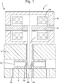
- Servo valve 1 comprises an electric motor 4, a flapper 2, nozzles 6 and a nozzle housing 8.
- the electric motor 4 comprises coils 4a, permanent magnets 4b and an armature 4c.
- the coils 4a are in electrical communication with an electrical supply (not shown) and when activated, interact with the permanent magnets 4b to create movement of the armature 4c, as is well-known in the art.
- the flapper 2 is attached to the armature 4c, and is deflected by movement of the armature 4c.
- the nozzles 6 are housed within the nozzle housing 8 via an interference fit and each comprise a fluid outlet 6a and a fluid inlet 6b.
- the nozzle housing 8 also has a pair of ports 8a, which allow communication of fluid to the nozzles 6.
- the flapper 2 comprises a blocking element 2a at an end thereof which interacts with the fluid outlets 6a of the nozzles 6 to provide metering of fluid from the fluid outlets 6a to a fluid port 8b in the nozzle housing 8, which allows communication of metered fluid from the nozzles 6 to an actuator (not shown).
- the electric motor 4 is used to control deflection of the blocking element 2a and vary the fluid delivered to the actuator from the nozzles 6 as required.
- Calibration of the servo valve 1 is achieved by adjusting the axial distance from the nozzle fluid outlet 6a to the flapper 2, by pulling or pushing the nozzles 6 axially (left or right) within the nozzle housing 8.
- a nozzle assembly N is illustrated for use in the servo valve of Figure 1 .
- the nozzle assembly N comprises a nozzle 10, a nozzle housing 8 and a locking pin 20.
- the nozzle housing 8 may be as shown in Figure 1 , receiving a pair of axially aligned nozzles 10.
- the nozzle 10 defines a central passage 18 having a fluid outlet 10a at a first end 12 and a fluid inlet 10b at an opposed second end 14.
- the nozzle housing 8 has a port 8a, which allows communication of fluid to the nozzle 10, a nozzle receiving bore 8c for receiving nozzle 10, and a locking pin receiving bore 30 for receiving the locking pin 20.
- the nozzle receiving bore 8c has a longitudinal axis X-X which in this embodiment is coaxial with the longitudinal axis of the nozzle 6.
- the locking pin receiving bore 30 has a central longitudinal axis Y-Y which is perpendicular to the axis X-X of the nozzle receiving bore 8c.
- the locking pin receiving bore 30 intersects the nozzle receiving bore 8c such that an aperture 34 is formed between the locking pin receiving bore 30 and the nozzle receiving bore 8c.
- the locking pin receiving bore 20 is, in this embodiment, arranged towards the inlet 14 of the nozzle 10. However, the axial position of the locking pin receiving bore 20 may be different in other embodiments.
- the locking pin receiving bore 30 and the nozzle receiving bore 8c are cylindrical in shape and circular in cross section, so that they may easily be formed by machining, for example drilling.
- this is not essential to the nozzle assembly construction and the respective bores 8c, 30 may be non-circular in cross section, for example square or rectangular in cross section.
- the locking pin receiving bore 30 at least need not be cylindrical and could have some other shape, for example a tapering shape or a rectangular prismatic shape.
- the nozzle 10 and locking pin 20 are also circular in cross section and have a complementary cylindrical shape to that of the nozzle receiving bore 8c and locking pin receiving bore 30 respectively.
- these bores 8c, 30 have a different shape from that shown, the nozzle 8 and locking pin 20 may have a different shape as well, for example complementary to the bore shapes.
- the locking pin receiving bore 30 is a through bore. This may be advantageous in that it allows the locking pin 20 to be accessible from both its ends which may facilitate its insertion or removal. However, this is not essential and the locking pin receiving bore 30 may, in other embodiments, be a blind bore, allowing access to just one end of the locking pin 20. In such an arrangement, the locking pin 20 may be provided with a suitable coupling at that end for the attachment of a tool for insertion or withdrawal of the locking pin 20 from the bore 30.
- the locking pin 20 is received completely within the locking pin receiving bore 30. Again this is not essential and the pin may project at one or more ends from the locking pin receiving bore 30.
- the locking pin 20 may be a push rod attached to a suitable actuator.
- the nozzle 10 may further comprise a threaded portion 38 on end 14 that can be removably secured to a calibration tool (not shown).
- the calibration tool may be a rod that can be threadably secured to the threaded portion 38 to allow the user to push or pull the nozzle 10 along the axis X-X.
- the intersection of the nozzle receiving bore 8c and the locking pin receiving bore 30 allows a portion 22 of the locking pin 20 to protrude through the aperture 34 so as to engage and interfere with a circumferential surface 36 of the nozzle 10 and thereby lock the nozzle 10 in position within the nozzle receiving bore 8c.
- the nozzle 10 is firstly "loosely” interference fitted within housing 8, such that nozzle 10 is relatively easily moveable along the longitudinal axis X-X during calibration, but at the same time still provides a leak-proof seal around the nozzle 10 during calibration.
- the nozzle 10 is moved to its desired axial position in the nozzle receiving bore 8c, for example using a calibration tool as described above.
- the locking pin 20 is received in the locking pin receiving bore 30 with a loose or close fit so that it may be moved along the axis Y-Y of the locking pin receiving bore 30. In other embodiments, the locking pin 20 could also be interference fit within receiving bore 30. In an initial position, the locking pin 20 is retracted relative to the aperture 34, but when the nozzle has been moved to its desired axial position, it is moved along the axis Y-Y to enter the aperture 34 and engage and interfere with the circumferential surface 36 of the nozzle 10.
- the movement of the locking pin should advantageously be purely translational and not rotational since a rotational movement may impart a force to the nozzle 10 with a component along the axis X-X, which could lead to unwanted axial movement of the nozzle 10.
- the arrangement of the axis Y-Y perpendicular to the axis X-X ensures that translational movement of the pin will not induce an axial force on the nozzle 10.
- the interference of the locking pin 20 with the nozzle 10 firmly locks the nozzle 10 in position. In effect it provides an additional frictional force between the nozzle 10 and the nozzle housing 8. In this way, in embodiments of the disclosure, the degree of interference between the nozzle 10 and the nozzle housing 8 can be reduced compared to a prior art nozzle, thereby facilitating calibration but still ensuring sufficient resistance to movement of the nozzle 10 at elevated temperatures.
- the dimensional tolerances between the nozzle 10 and nozzle housing 8 may be reduced compared to prior art nozzles, possibly avoiding the need for grinding of the circumferential surface 36 of the nozzle 10 and burnishing of the nozzle receiving bore 8c of the nozzle housing 8. This may reduce the cost of manufacturing the nozzle assembly N.
- the described embodiment may also facilitate refurbishment or repair of the nozzle assembly N, allowing for easier removal of the nozzle 10 from the nozzle housing 8.
Landscapes
- Engineering & Computer Science (AREA)
- General Engineering & Computer Science (AREA)
- Mechanical Engineering (AREA)
- Physics & Mathematics (AREA)
- Fluid Mechanics (AREA)
- Theoretical Computer Science (AREA)
- Nozzles (AREA)
- Fuel-Injection Apparatus (AREA)
Abstract
Description
- This disclosure relates to a nozzle assembly, and more specifically, but not exclusively, to a nozzle assembly of a servo valve.
- This disclosure also relates to a servo valve, a method of assembling a nozzle assembly and a method of calibrating a nozzle assembly.
- Servo valves are well-known in the art and can be used to control how much fluid is ported to an actuator. Typically, a flapper is deflected by an armature connected to an electric motor away or towards nozzles, which inject the fluid. Deflection of the flapper can control the amount of fluid injected from the nozzles, and thus the amount of fluid communicated to the actuator. In this way, servo valves can allow precise control of actuator movement. Calibration of the servo valve is often required to ensure the correct control of actuator movement is realised, and is achieved by adjusting the axial distance from the nozzle outlet to the flapper.
- Typically, the nozzles are interference fitted into a nozzle housing. The interference fit of the nozzle into the housing has to be very tight to ensure that it remains in the correct position within the housing at all operating temperatures. This tight fit can make it difficult to calibrate the servo valve, as it may make it difficult to move the nozzle axially within the nozzle housing.
- From one aspect, the present disclosure relates to a nozzle assembly in accordance with
claim 1. - In one embodiment of the above nozzle assembly, the nozzle is received with an interference fit within the nozzle receiving bore.
- In a further embodiment of any of the above nozzle assemblies, the locking pin is received with a close or loose fit in the locking pin receiving bore.
- In a further embodiment of any of the above nozzle assemblies, the nozzle receiving bore is cylindrical.
- In a further embodiment of any of the above nozzle assemblies, the locking pin receiving bore is cylindrical.
- In a further embodiment of any of the above nozzle assemblies, the locking pin receiving bore is a through bore.
- In a further embodiment of any of the above nozzle assemblies, the nozzle receiving bore is circular in cross section. In addition or alternatively, the locking pin receiving bore is circular in cross section.
- In a further embodiment of any of the above nozzle assemblies, the nozzle is circular in cross section. In addition or alternatively, the locking pin is circular in cross section.
- In a further embodiment of any of the above nozzle assemblies, the nozzle is provided with a threaded connection at one end for connection to a calibration tool.
- In a further embodiment of any of the above nozzle assemblies, the nozzle receiving bore receives a pair of opposed nozzles.
- From another aspect, the present disclosure relates to a servo valve comprising the nozzle assembly of any of the above embodiments.
- From yet another aspect, the present disclosure relates to a method of assembling a nozzle assembly in accordance with
claim 12. - From yet another aspect, the present disclosure relates to a method of calibrating a nozzle assembly in accordance with claim 13.
- In one embodiment of the above method, the nozzle is received in the nozzle receiving bore with an interference fit.
- In a further embodiment of any of the above methods of calibrating a nozzle assembly, the nozzle is inserted or moved in the nozzle receiving bore by a tool engaging an end of the nozzle.
- Some exemplary embodiments of the present disclosure will now be described by way of example only, and with reference to the following drawings in which:
-
Figure 1 shows an example of a prior art servo valve; -
Figure 2a shows a perspective cross-sectional view of an embodiment of a nozzle assembly in accordance with this disclosure, with the locking pin removed; -
Figure 2b shows a perspective cross-sectional view of an embodiment of a nozzle assembly in accordance with this disclosure, with the locking pin inserted; -
Figure 3 shows a cross-sectional view of the nozzle assembly ofFigure 2a taken through line 3-3; -
Figures 4a shows a cross-sectional view of a nozzle assembly in accordance with an embodiment of this disclosure; and -
Figures 4b shows a magnified view of the area around the locking pin in the nozzle assembly ofFigure 4a ; - With reference to
Figure 1 , aservo valve 1 is illustrated.Servo valve 1 comprises anelectric motor 4, aflapper 2,nozzles 6 and anozzle housing 8. Theelectric motor 4 comprisescoils 4a,permanent magnets 4b and anarmature 4c. Thecoils 4a are in electrical communication with an electrical supply (not shown) and when activated, interact with thepermanent magnets 4b to create movement of thearmature 4c, as is well-known in the art. - The
flapper 2 is attached to thearmature 4c, and is deflected by movement of thearmature 4c. Thenozzles 6 are housed within thenozzle housing 8 via an interference fit and each comprise afluid outlet 6a and afluid inlet 6b. Thenozzle housing 8 also has a pair ofports 8a, which allow communication of fluid to thenozzles 6. - The
flapper 2 comprises ablocking element 2a at an end thereof which interacts with thefluid outlets 6a of thenozzles 6 to provide metering of fluid from thefluid outlets 6a to afluid port 8b in thenozzle housing 8, which allows communication of metered fluid from thenozzles 6 to an actuator (not shown). As is known in the art, theelectric motor 4 is used to control deflection of theblocking element 2a and vary the fluid delivered to the actuator from thenozzles 6 as required. - Calibration of the
servo valve 1 is achieved by adjusting the axial distance from thenozzle fluid outlet 6a to theflapper 2, by pulling or pushing thenozzles 6 axially (left or right) within thenozzle housing 8. - With reference to
Figures 2a to 4b , a nozzle assembly N is illustrated for use in the servo valve ofFigure 1 . The nozzle assembly N comprises anozzle 10, anozzle housing 8 and alocking pin 20. In fact, thenozzle housing 8 may be as shown inFigure 1 , receiving a pair of axially alignednozzles 10. - The
nozzle 10 defines acentral passage 18 having afluid outlet 10a at afirst end 12 and afluid inlet 10b at an opposedsecond end 14. - The
nozzle housing 8 has aport 8a, which allows communication of fluid to thenozzle 10, a nozzle receivingbore 8c for receivingnozzle 10, and a locking pin receivingbore 30 for receiving thelocking pin 20. The nozzle receivingbore 8c has a longitudinal axis X-X which in this embodiment is coaxial with the longitudinal axis of thenozzle 6. - The locking pin receiving
bore 30 has a central longitudinal axis Y-Y which is perpendicular to the axis X-X of thenozzle receiving bore 8c. The locking pin receivingbore 30 intersects the nozzle receivingbore 8c such that anaperture 34 is formed between the locking pin receivingbore 30 and thenozzle receiving bore 8c. - The locking pin receiving
bore 20 is, in this embodiment, arranged towards theinlet 14 of thenozzle 10. However, the axial position of the locking pin receivingbore 20 may be different in other embodiments. - In this embodiment, the locking pin receiving
bore 30 and thenozzle receiving bore 8c are cylindrical in shape and circular in cross section, so that they may easily be formed by machining, for example drilling. However, this is not essential to the nozzle assembly construction and therespective bores bore 30 at least need not be cylindrical and could have some other shape, for example a tapering shape or a rectangular prismatic shape. - In this embodiment, the
nozzle 10 andlocking pin 20 are also circular in cross section and have a complementary cylindrical shape to that of the nozzle receivingbore 8c and locking pin receivingbore 30 respectively. Of course if thesebores nozzle 8 and lockingpin 20 may have a different shape as well, for example complementary to the bore shapes. - In the embodiment illustrated, the locking pin receiving
bore 30 is a through bore. This may be advantageous in that it allows the lockingpin 20 to be accessible from both its ends which may facilitate its insertion or removal. However, this is not essential and the locking pin receiving bore 30 may, in other embodiments, be a blind bore, allowing access to just one end of the lockingpin 20. In such an arrangement, the lockingpin 20 may be provided with a suitable coupling at that end for the attachment of a tool for insertion or withdrawal of the lockingpin 20 from thebore 30. - Also in the illustrated embodiment, the locking
pin 20 is received completely within the lockingpin receiving bore 30. Again this is not essential and the pin may project at one or more ends from the lockingpin receiving bore 30. In one embodiment, for example, the lockingpin 20 may be a push rod attached to a suitable actuator. - To facilitate calibration, the
nozzle 10 may further comprise a threadedportion 38 onend 14 that can be removably secured to a calibration tool (not shown). The calibration tool may be a rod that can be threadably secured to the threadedportion 38 to allow the user to push or pull thenozzle 10 along the axis X-X. - As illustrated in
Figures 4a and 4b , the intersection of the nozzle receiving bore 8c and the locking pin receiving bore 30 allows aportion 22 of the lockingpin 20 to protrude through theaperture 34 so as to engage and interfere with acircumferential surface 36 of thenozzle 10 and thereby lock thenozzle 10 in position within thenozzle receiving bore 8c. - Installation and calibration of the
nozzle 10 will now be described. - The
nozzle 10 is firstly "loosely" interference fitted withinhousing 8, such thatnozzle 10 is relatively easily moveable along the longitudinal axis X-X during calibration, but at the same time still provides a leak-proof seal around thenozzle 10 during calibration. Thenozzle 10 is moved to its desired axial position in the nozzle receiving bore 8c, for example using a calibration tool as described above. - The locking
pin 20 is received in the locking pin receiving bore 30 with a loose or close fit so that it may be moved along the axis Y-Y of the lockingpin receiving bore 30. In other embodiments, the lockingpin 20 could also be interference fit within receivingbore 30. In an initial position, the lockingpin 20 is retracted relative to theaperture 34, but when the nozzle has been moved to its desired axial position, it is moved along the axis Y-Y to enter theaperture 34 and engage and interfere with thecircumferential surface 36 of thenozzle 10. The movement of the locking pin should advantageously be purely translational and not rotational since a rotational movement may impart a force to thenozzle 10 with a component along the axis X-X, which could lead to unwanted axial movement of thenozzle 10. The arrangement of the axis Y-Y perpendicular to the axis X-X ensures that translational movement of the pin will not induce an axial force on thenozzle 10. - The interference of the locking
pin 20 with thenozzle 10 firmly locks thenozzle 10 in position. In effect it provides an additional frictional force between thenozzle 10 and thenozzle housing 8. In this way, in embodiments of the disclosure, the degree of interference between thenozzle 10 and thenozzle housing 8 can be reduced compared to a prior art nozzle, thereby facilitating calibration but still ensuring sufficient resistance to movement of thenozzle 10 at elevated temperatures. - It may also mean that the dimensional tolerances between the
nozzle 10 andnozzle housing 8 may be reduced compared to prior art nozzles, possibly avoiding the need for grinding of thecircumferential surface 36 of thenozzle 10 and burnishing of the nozzle receiving bore 8c of thenozzle housing 8. This may reduce the cost of manufacturing the nozzle assembly N. - The described embodiment may also facilitate refurbishment or repair of the nozzle assembly N, allowing for easier removal of the
nozzle 10 from thenozzle housing 8. - Although the figures and the accompanying description describe particular embodiments and examples, it is to be understood that the scope of this disclosure is not to be limited to such specific embodiments, and is, instead, to be determined by the following claims.
Claims (15)
- A nozzle assembly (N) comprising:a nozzle (10);a nozzle housing (8) having a nozzle receiving bore (8c) having a longitudinal axis (X-X), the nozzle (10) being received within the nozzle receiving bore (8c);a locking pin receiving bore (30) having a longitudinal axis (Y-Y) that is perpendicular to the nozzle housing axis (X-X), the locking pin receiving bore (30) intersecting the nozzle receiving bore (8c), whereby an aperture (34) is formed between the locking pin receiving bore (30) and the nozzle receiving bore (8c);a locking pin (20) received in the locking pin receiving bore (30), a portion (22) of the locking pin (20) protruding through the aperture (34) and into the nozzle receiving bore (8c) so as to engage and interfere with a circumferential portion (36) of the nozzle (10).
- A nozzle assembly as claimed in claim 1, wherein the nozzle (10) is received with an interference fit within the nozzle receiving bore (8c).
- A nozzle assembly as claimed in claim 1 or 2, wherein the locking pin (32) is received with a close or loose fit in the locking pin receiving bore (30).
- A nozzle assembly as claimed in any preceding claim, wherein the nozzle receiving bore (8c) is cylindrical.
- A nozzle assembly as claimed in any preceding claim, wherein the locking pin receiving bore (30) is cylindrical.
- A nozzle assembly as claimed in any preceding claim, wherein the locking pin receiving bore (30) is a through bore.
- A nozzle assembly as claimed in any preceding claim, wherein the nozzle receiving bore (8c) and/or the locking pin receiving bore (30) are circular in cross section.
- A nozzle assembly as claimed in any preceding claim, wherein the nozzle (10) and/or the locking pin (20) are circular in cross section.
- A nozzle assembly as claimed in any preceding claim, wherein the nozzle (10) is provided with a threaded connection (38) at one end (14) for connection to a calibration tool.
- A nozzle assembly as claimed in any preceding claim, wherein the nozzle receiving bore (8c) receives a pair of opposed nozzles (10).
- A servo valve comprising a nozzle assembly as claimed in any preceding claim.
- A method of assembling a nozzle assembly comprising:providing a nozzle housing (8) having a nozzle receiving bore (8c) having a longitudinal axis (X-X) and a locking pin receiving bore (30) having a longitudinal axis (Y-Y) perpendicular to the longitudinal axis (X-X) of the nozzle receiving bore (8c) and intersecting the nozzle receiving bore (8), whereby an aperture (34) is formed between the locking pin receiving bore (30) and the nozzle receiving bore (8c);inserting a nozzle (10) into the nozzle receiving bore (8c); andinserting a locking pin (20) into the locking pin receiving bore (30) such that a portion (22) of the locking pin (20) protrudes through the aperture (34) and presses onto a circumferential portion (36) of the nozzle (10) to lock the nozzle (10) in position within the nozzle receiving bore (8c).
- A method of calibrating a nozzle assembly which comprises a nozzle housing (8) having a nozzle receiving bore (8c) having a longitudinal axis X-X and a locking pin receiving bore (30) having an axis (Y-Y) perpendicular to the axis (X-X) of the nozzle receiving bore (8) and intersecting the nozzle receiving bore (8), whereby an aperture (34) is formed between the locking pin receiving bore (30) and the nozzle receiving bore (8c); the method comprising:moving a nozzle (10) in the nozzle receiving bore (8c) to a desired axial position within the nozzle receiving bore (8c); andinserting a locking pin (20) into the locking pin receiving bore (30) such that a portion (22) of the locking pin (20) protrudes through the aperture (34) and presses onto a circumferential portion (36) of the nozzle (10) to lock the nozzle (10) in the desired axial position within the nozzle receiving bore (8c).
- A method as claimed in claim 12 or 13, wherein the nozzle (10) is received in the nozzle receiving bore (8c) with an interference fit.
- A method as claimed in claim 12, 13 or 14, wherein the nozzle (10) is inserted or moved in the nozzle receiving bore (8c) by a tool engaging an end (14) of the nozzle (10).
Priority Applications (2)
| Application Number | Priority Date | Filing Date | Title |
|---|---|---|---|
| EP17461549.2A EP3418585B1 (en) | 2017-06-19 | 2017-06-19 | Servo valve comprising a nozzle assembly |
| US15/964,152 US20180363684A1 (en) | 2017-06-19 | 2018-04-27 | Nozzle assembly |
Applications Claiming Priority (1)
| Application Number | Priority Date | Filing Date | Title |
|---|---|---|---|
| EP17461549.2A EP3418585B1 (en) | 2017-06-19 | 2017-06-19 | Servo valve comprising a nozzle assembly |
Publications (2)
| Publication Number | Publication Date |
|---|---|
| EP3418585A1 true EP3418585A1 (en) | 2018-12-26 |
| EP3418585B1 EP3418585B1 (en) | 2021-08-04 |
Family
ID=59091462
Family Applications (1)
| Application Number | Title | Priority Date | Filing Date |
|---|---|---|---|
| EP17461549.2A Active EP3418585B1 (en) | 2017-06-19 | 2017-06-19 | Servo valve comprising a nozzle assembly |
Country Status (2)
| Country | Link |
|---|---|
| US (1) | US20180363684A1 (en) |
| EP (1) | EP3418585B1 (en) |
Families Citing this family (1)
| Publication number | Priority date | Publication date | Assignee | Title |
|---|---|---|---|---|
| EP3517812B1 (en) * | 2018-01-30 | 2020-08-12 | Hamilton Sundstrand Corporation | Torque motor with double fix screws |
Citations (3)
| Publication number | Priority date | Publication date | Assignee | Title |
|---|---|---|---|---|
| DE1954798A1 (en) * | 1969-10-31 | 1972-01-13 | Indramat Gmbh | Control slide combined with a throttle gap regulating device |
| US6755205B1 (en) * | 2002-09-12 | 2004-06-29 | Woodward Governor Company | Method to stabilize a nozzle flapper valve |
| DE102005022535A1 (en) * | 2005-05-17 | 2006-11-23 | Siemens Ag | Nozzle group for injection valve comprises base body, needle guide body, nozzle needle movable within guide body, overlap area containing groove on guide body with anti-twist device; injection valve with said nozzle group |
Family Cites Families (3)
| Publication number | Priority date | Publication date | Assignee | Title |
|---|---|---|---|---|
| US3556150A (en) * | 1969-05-12 | 1971-01-19 | Borg Warner | Electro hydraulic servovalve |
| US4519638A (en) * | 1982-03-19 | 1985-05-28 | Higashio Pipe Fittings Mfg. Co., Ltd. | Pipe joint |
| US5070898A (en) * | 1991-02-11 | 1991-12-10 | Hsc Controls Inc. | Metering valve |
-
2017
- 2017-06-19 EP EP17461549.2A patent/EP3418585B1/en active Active
-
2018
- 2018-04-27 US US15/964,152 patent/US20180363684A1/en not_active Abandoned
Patent Citations (3)
| Publication number | Priority date | Publication date | Assignee | Title |
|---|---|---|---|---|
| DE1954798A1 (en) * | 1969-10-31 | 1972-01-13 | Indramat Gmbh | Control slide combined with a throttle gap regulating device |
| US6755205B1 (en) * | 2002-09-12 | 2004-06-29 | Woodward Governor Company | Method to stabilize a nozzle flapper valve |
| DE102005022535A1 (en) * | 2005-05-17 | 2006-11-23 | Siemens Ag | Nozzle group for injection valve comprises base body, needle guide body, nozzle needle movable within guide body, overlap area containing groove on guide body with anti-twist device; injection valve with said nozzle group |
Also Published As
| Publication number | Publication date |
|---|---|
| EP3418585B1 (en) | 2021-08-04 |
| US20180363684A1 (en) | 2018-12-20 |
Similar Documents
| Publication | Publication Date | Title |
|---|---|---|
| DE102013111456B4 (en) | shut-off valve | |
| EP2539614B1 (en) | Electromagnetic hydraulic valve | |
| WO2017084662A1 (en) | Electromagnetic control device | |
| EP3418585B1 (en) | Servo valve comprising a nozzle assembly | |
| DE102010031328B4 (en) | Solenoid valve and driver assistance device | |
| US8011385B2 (en) | Valve assembly and method of assembly | |
| WO2014154716A1 (en) | Pipe connection adapter and sanitary fitting | |
| AT410018B (en) | MULTIPLE VALVE | |
| WO2010149256A1 (en) | Device for connecting two line sections, in particular a multi-coupling having an integrated shut-off valve | |
| EP3445975B1 (en) | Ejector device and combination of a cylinder head cover and ejector device | |
| US11506291B2 (en) | Filter retaining plug and tool | |
| DE102006041562B4 (en) | Actuating device for an internal combustion engine | |
| EP4072915A1 (en) | Electromagnetic valve | |
| DE102012023750B3 (en) | Valve device for use as cartridge valve or screw-in cartridge valve in hydraulic systems, has valve housing and valve piston connected with operating magnet device through coupling device, where coupling device has coupling elements | |
| EP3563076B1 (en) | Electromagnetic hinged armature valve device | |
| WO2015172866A1 (en) | Connection unit for a coupling device, in particular a multiple coupling | |
| DE10319632B4 (en) | Pilot solenoid valve | |
| EP2896858B1 (en) | Valve control actuator | |
| EP3715687B1 (en) | Servo valves | |
| EP3597972B1 (en) | Nozzle and nozzle assembly for a servo valve | |
| EP3070721B1 (en) | Actuation device | |
| DE19736719C1 (en) | Electropneumatic valve with actuator drive | |
| DE102016206615A1 (en) | Ejector device and combination of a cylinder head cover and an ejector device | |
| EP3557103B1 (en) | Flapper servo valve nozzle housing | |
| DE102010047414A1 (en) | Camshaft adjustment device has actuator for actuating camshaft adjuster, where base body and fixing unit are provided, and fixing unit has two locking elements interlocked into one another |
Legal Events
| Date | Code | Title | Description |
|---|---|---|---|
| PUAI | Public reference made under article 153(3) epc to a published international application that has entered the european phase |
Free format text: ORIGINAL CODE: 0009012 |
|
| STAA | Information on the status of an ep patent application or granted ep patent |
Free format text: STATUS: THE APPLICATION HAS BEEN PUBLISHED |
|
| AK | Designated contracting states |
Kind code of ref document: A1 Designated state(s): AL AT BE BG CH CY CZ DE DK EE ES FI FR GB GR HR HU IE IS IT LI LT LU LV MC MK MT NL NO PL PT RO RS SE SI SK SM TR |
|
| AX | Request for extension of the european patent |
Extension state: BA ME |
|
| STAA | Information on the status of an ep patent application or granted ep patent |
Free format text: STATUS: REQUEST FOR EXAMINATION WAS MADE |
|
| 17P | Request for examination filed |
Effective date: 20190625 |
|
| RBV | Designated contracting states (corrected) |
Designated state(s): AL AT BE BG CH CY CZ DE DK EE ES FI FR GB GR HR HU IE IS IT LI LT LU LV MC MK MT NL NO PL PT RO RS SE SI SK SM TR |
|
| GRAP | Despatch of communication of intention to grant a patent |
Free format text: ORIGINAL CODE: EPIDOSNIGR1 |
|
| STAA | Information on the status of an ep patent application or granted ep patent |
Free format text: STATUS: GRANT OF PATENT IS INTENDED |
|
| INTG | Intention to grant announced |
Effective date: 20210113 |
|
| RIN1 | Information on inventor provided before grant (corrected) |
Inventor name: KOZLOWSKI, PIOTR Inventor name: SAWICKI, PIOTR |
|
| GRAS | Grant fee paid |
Free format text: ORIGINAL CODE: EPIDOSNIGR3 |
|
| RAP3 | Party data changed (applicant data changed or rights of an application transferred) |
Owner name: HAMILTON SUNDSTRAND CORPORATION |
|
| GRAA | (expected) grant |
Free format text: ORIGINAL CODE: 0009210 |
|
| STAA | Information on the status of an ep patent application or granted ep patent |
Free format text: STATUS: THE PATENT HAS BEEN GRANTED |
|
| AK | Designated contracting states |
Kind code of ref document: B1 Designated state(s): AL AT BE BG CH CY CZ DE DK EE ES FI FR GB GR HR HU IE IS IT LI LT LU LV MC MK MT NL NO PL PT RO RS SE SI SK SM TR |
|
| REG | Reference to a national code |
Ref country code: GB Ref legal event code: FG4D |
|
| REG | Reference to a national code |
Ref country code: AT Ref legal event code: REF Ref document number: 1417255 Country of ref document: AT Kind code of ref document: T Effective date: 20210815 |
|
| REG | Reference to a national code |
Ref country code: CH Ref legal event code: EP |
|
| REG | Reference to a national code |
Ref country code: DE Ref legal event code: R096 Ref document number: 602017043282 Country of ref document: DE |
|
| REG | Reference to a national code |
Ref country code: IE Ref legal event code: FG4D |
|
| REG | Reference to a national code |
Ref country code: LT Ref legal event code: MG9D |
|
| REG | Reference to a national code |
Ref country code: NL Ref legal event code: MP Effective date: 20210804 |
|
| REG | Reference to a national code |
Ref country code: AT Ref legal event code: MK05 Ref document number: 1417255 Country of ref document: AT Kind code of ref document: T Effective date: 20210804 |
|
| PG25 | Lapsed in a contracting state [announced via postgrant information from national office to epo] |
Ref country code: SE Free format text: LAPSE BECAUSE OF FAILURE TO SUBMIT A TRANSLATION OF THE DESCRIPTION OR TO PAY THE FEE WITHIN THE PRESCRIBED TIME-LIMIT Effective date: 20210804 Ref country code: RS Free format text: LAPSE BECAUSE OF FAILURE TO SUBMIT A TRANSLATION OF THE DESCRIPTION OR TO PAY THE FEE WITHIN THE PRESCRIBED TIME-LIMIT Effective date: 20210804 Ref country code: HR Free format text: LAPSE BECAUSE OF FAILURE TO SUBMIT A TRANSLATION OF THE DESCRIPTION OR TO PAY THE FEE WITHIN THE PRESCRIBED TIME-LIMIT Effective date: 20210804 Ref country code: PT Free format text: LAPSE BECAUSE OF FAILURE TO SUBMIT A TRANSLATION OF THE DESCRIPTION OR TO PAY THE FEE WITHIN THE PRESCRIBED TIME-LIMIT Effective date: 20211206 Ref country code: NO Free format text: LAPSE BECAUSE OF FAILURE TO SUBMIT A TRANSLATION OF THE DESCRIPTION OR TO PAY THE FEE WITHIN THE PRESCRIBED TIME-LIMIT Effective date: 20211104 Ref country code: FI Free format text: LAPSE BECAUSE OF FAILURE TO SUBMIT A TRANSLATION OF THE DESCRIPTION OR TO PAY THE FEE WITHIN THE PRESCRIBED TIME-LIMIT Effective date: 20210804 Ref country code: ES Free format text: LAPSE BECAUSE OF FAILURE TO SUBMIT A TRANSLATION OF THE DESCRIPTION OR TO PAY THE FEE WITHIN THE PRESCRIBED TIME-LIMIT Effective date: 20210804 Ref country code: BG Free format text: LAPSE BECAUSE OF FAILURE TO SUBMIT A TRANSLATION OF THE DESCRIPTION OR TO PAY THE FEE WITHIN THE PRESCRIBED TIME-LIMIT Effective date: 20211104 Ref country code: AT Free format text: LAPSE BECAUSE OF FAILURE TO SUBMIT A TRANSLATION OF THE DESCRIPTION OR TO PAY THE FEE WITHIN THE PRESCRIBED TIME-LIMIT Effective date: 20210804 Ref country code: LT Free format text: LAPSE BECAUSE OF FAILURE TO SUBMIT A TRANSLATION OF THE DESCRIPTION OR TO PAY THE FEE WITHIN THE PRESCRIBED TIME-LIMIT Effective date: 20210804 |
|
| PG25 | Lapsed in a contracting state [announced via postgrant information from national office to epo] |
Ref country code: PL Free format text: LAPSE BECAUSE OF FAILURE TO SUBMIT A TRANSLATION OF THE DESCRIPTION OR TO PAY THE FEE WITHIN THE PRESCRIBED TIME-LIMIT Effective date: 20210804 Ref country code: LV Free format text: LAPSE BECAUSE OF FAILURE TO SUBMIT A TRANSLATION OF THE DESCRIPTION OR TO PAY THE FEE WITHIN THE PRESCRIBED TIME-LIMIT Effective date: 20210804 Ref country code: GR Free format text: LAPSE BECAUSE OF FAILURE TO SUBMIT A TRANSLATION OF THE DESCRIPTION OR TO PAY THE FEE WITHIN THE PRESCRIBED TIME-LIMIT Effective date: 20211105 |
|
| PG25 | Lapsed in a contracting state [announced via postgrant information from national office to epo] |
Ref country code: NL Free format text: LAPSE BECAUSE OF FAILURE TO SUBMIT A TRANSLATION OF THE DESCRIPTION OR TO PAY THE FEE WITHIN THE PRESCRIBED TIME-LIMIT Effective date: 20210804 |
|
| PG25 | Lapsed in a contracting state [announced via postgrant information from national office to epo] |
Ref country code: DK Free format text: LAPSE BECAUSE OF FAILURE TO SUBMIT A TRANSLATION OF THE DESCRIPTION OR TO PAY THE FEE WITHIN THE PRESCRIBED TIME-LIMIT Effective date: 20210804 |
|
| REG | Reference to a national code |
Ref country code: DE Ref legal event code: R097 Ref document number: 602017043282 Country of ref document: DE |
|
| PG25 | Lapsed in a contracting state [announced via postgrant information from national office to epo] |
Ref country code: SM Free format text: LAPSE BECAUSE OF FAILURE TO SUBMIT A TRANSLATION OF THE DESCRIPTION OR TO PAY THE FEE WITHIN THE PRESCRIBED TIME-LIMIT Effective date: 20210804 Ref country code: SK Free format text: LAPSE BECAUSE OF FAILURE TO SUBMIT A TRANSLATION OF THE DESCRIPTION OR TO PAY THE FEE WITHIN THE PRESCRIBED TIME-LIMIT Effective date: 20210804 Ref country code: RO Free format text: LAPSE BECAUSE OF FAILURE TO SUBMIT A TRANSLATION OF THE DESCRIPTION OR TO PAY THE FEE WITHIN THE PRESCRIBED TIME-LIMIT Effective date: 20210804 Ref country code: EE Free format text: LAPSE BECAUSE OF FAILURE TO SUBMIT A TRANSLATION OF THE DESCRIPTION OR TO PAY THE FEE WITHIN THE PRESCRIBED TIME-LIMIT Effective date: 20210804 Ref country code: CZ Free format text: LAPSE BECAUSE OF FAILURE TO SUBMIT A TRANSLATION OF THE DESCRIPTION OR TO PAY THE FEE WITHIN THE PRESCRIBED TIME-LIMIT Effective date: 20210804 Ref country code: AL Free format text: LAPSE BECAUSE OF FAILURE TO SUBMIT A TRANSLATION OF THE DESCRIPTION OR TO PAY THE FEE WITHIN THE PRESCRIBED TIME-LIMIT Effective date: 20210804 |
|
| PLBE | No opposition filed within time limit |
Free format text: ORIGINAL CODE: 0009261 |
|
| STAA | Information on the status of an ep patent application or granted ep patent |
Free format text: STATUS: NO OPPOSITION FILED WITHIN TIME LIMIT |
|
| 26N | No opposition filed |
Effective date: 20220506 |
|
| PG25 | Lapsed in a contracting state [announced via postgrant information from national office to epo] |
Ref country code: IT Free format text: LAPSE BECAUSE OF FAILURE TO SUBMIT A TRANSLATION OF THE DESCRIPTION OR TO PAY THE FEE WITHIN THE PRESCRIBED TIME-LIMIT Effective date: 20210804 |
|
| PG25 | Lapsed in a contracting state [announced via postgrant information from national office to epo] |
Ref country code: SI Free format text: LAPSE BECAUSE OF FAILURE TO SUBMIT A TRANSLATION OF THE DESCRIPTION OR TO PAY THE FEE WITHIN THE PRESCRIBED TIME-LIMIT Effective date: 20210804 |
|
| REG | Reference to a national code |
Ref country code: DE Ref legal event code: R119 Ref document number: 602017043282 Country of ref document: DE |
|
| PG25 | Lapsed in a contracting state [announced via postgrant information from national office to epo] |
Ref country code: MC Free format text: LAPSE BECAUSE OF FAILURE TO SUBMIT A TRANSLATION OF THE DESCRIPTION OR TO PAY THE FEE WITHIN THE PRESCRIBED TIME-LIMIT Effective date: 20210804 |
|
| REG | Reference to a national code |
Ref country code: CH Ref legal event code: PL |
|
| REG | Reference to a national code |
Ref country code: BE Ref legal event code: MM Effective date: 20220630 |
|
| GBPC | Gb: european patent ceased through non-payment of renewal fee |
Effective date: 20220619 |
|
| PG25 | Lapsed in a contracting state [announced via postgrant information from national office to epo] |
Ref country code: LU Free format text: LAPSE BECAUSE OF NON-PAYMENT OF DUE FEES Effective date: 20220619 Ref country code: LI Free format text: LAPSE BECAUSE OF NON-PAYMENT OF DUE FEES Effective date: 20220630 Ref country code: IE Free format text: LAPSE BECAUSE OF NON-PAYMENT OF DUE FEES Effective date: 20220619 Ref country code: FR Free format text: LAPSE BECAUSE OF NON-PAYMENT OF DUE FEES Effective date: 20220630 Ref country code: CH Free format text: LAPSE BECAUSE OF NON-PAYMENT OF DUE FEES Effective date: 20220630 |
|
| PG25 | Lapsed in a contracting state [announced via postgrant information from national office to epo] |
Ref country code: GB Free format text: LAPSE BECAUSE OF NON-PAYMENT OF DUE FEES Effective date: 20220619 Ref country code: DE Free format text: LAPSE BECAUSE OF NON-PAYMENT OF DUE FEES Effective date: 20230103 Ref country code: BE Free format text: LAPSE BECAUSE OF NON-PAYMENT OF DUE FEES Effective date: 20220630 |
|
| PG25 | Lapsed in a contracting state [announced via postgrant information from national office to epo] |
Ref country code: HU Free format text: LAPSE BECAUSE OF FAILURE TO SUBMIT A TRANSLATION OF THE DESCRIPTION OR TO PAY THE FEE WITHIN THE PRESCRIBED TIME-LIMIT; INVALID AB INITIO Effective date: 20170619 |
|
| PG25 | Lapsed in a contracting state [announced via postgrant information from national office to epo] |
Ref country code: MK Free format text: LAPSE BECAUSE OF FAILURE TO SUBMIT A TRANSLATION OF THE DESCRIPTION OR TO PAY THE FEE WITHIN THE PRESCRIBED TIME-LIMIT Effective date: 20210804 Ref country code: CY Free format text: LAPSE BECAUSE OF FAILURE TO SUBMIT A TRANSLATION OF THE DESCRIPTION OR TO PAY THE FEE WITHIN THE PRESCRIBED TIME-LIMIT Effective date: 20210804 |
|
| PG25 | Lapsed in a contracting state [announced via postgrant information from national office to epo] |
Ref country code: MT Free format text: LAPSE BECAUSE OF FAILURE TO SUBMIT A TRANSLATION OF THE DESCRIPTION OR TO PAY THE FEE WITHIN THE PRESCRIBED TIME-LIMIT Effective date: 20210804 |
|
| PG25 | Lapsed in a contracting state [announced via postgrant information from national office to epo] |
Ref country code: TR Free format text: LAPSE BECAUSE OF FAILURE TO SUBMIT A TRANSLATION OF THE DESCRIPTION OR TO PAY THE FEE WITHIN THE PRESCRIBED TIME-LIMIT Effective date: 20210804 |