EP3418571A1 - Gear pump with means for reduction of cavitation - Google Patents
Gear pump with means for reduction of cavitation Download PDFInfo
- Publication number
- EP3418571A1 EP3418571A1 EP18179640.0A EP18179640A EP3418571A1 EP 3418571 A1 EP3418571 A1 EP 3418571A1 EP 18179640 A EP18179640 A EP 18179640A EP 3418571 A1 EP3418571 A1 EP 3418571A1
- Authority
- EP
- European Patent Office
- Prior art keywords
- contact point
- bearing
- tooth
- gear
- volume
- Prior art date
- Legal status (The legal status is an assumption and is not a legal conclusion. Google has not performed a legal analysis and makes no representation as to the accuracy of the status listed.)
- Granted
Links
- 230000009467 reduction Effects 0.000 title description 3
- 239000012530 fluid Substances 0.000 claims abstract description 61
- 238000005259 measurement Methods 0.000 claims abstract description 33
- 230000008859 change Effects 0.000 claims abstract description 27
- 230000003247 decreasing effect Effects 0.000 claims abstract description 23
- 239000000446 fuel Substances 0.000 claims description 49
- 230000009471 action Effects 0.000 claims description 17
- 238000000034 method Methods 0.000 description 11
- 238000007789 sealing Methods 0.000 description 9
- 238000013461 design Methods 0.000 description 8
- 230000000670 limiting effect Effects 0.000 description 5
- 230000008878 coupling Effects 0.000 description 4
- 238000010168 coupling process Methods 0.000 description 4
- 238000005859 coupling reaction Methods 0.000 description 4
- 230000003628 erosive effect Effects 0.000 description 4
- 239000002828 fuel tank Substances 0.000 description 4
- 230000010355 oscillation Effects 0.000 description 4
- 238000012546 transfer Methods 0.000 description 4
- 230000015572 biosynthetic process Effects 0.000 description 3
- 230000007423 decrease Effects 0.000 description 3
- 239000007788 liquid Substances 0.000 description 3
- 230000008569 process Effects 0.000 description 3
- 238000007493 shaping process Methods 0.000 description 3
- 239000000463 material Substances 0.000 description 2
- 230000003864 performance function Effects 0.000 description 2
- 238000005086 pumping Methods 0.000 description 2
- 230000002829 reductive effect Effects 0.000 description 2
- 238000013022 venting Methods 0.000 description 2
- 238000004891 communication Methods 0.000 description 1
- 230000001010 compromised effect Effects 0.000 description 1
- 230000006866 deterioration Effects 0.000 description 1
- 238000010586 diagram Methods 0.000 description 1
- 238000006073 displacement reaction Methods 0.000 description 1
- 230000009977 dual effect Effects 0.000 description 1
- 230000000694 effects Effects 0.000 description 1
- 230000008030 elimination Effects 0.000 description 1
- 238000003379 elimination reaction Methods 0.000 description 1
- 238000012986 modification Methods 0.000 description 1
- 230000004048 modification Effects 0.000 description 1
- 230000036961 partial effect Effects 0.000 description 1
- 230000000737 periodic effect Effects 0.000 description 1
- 230000001105 regulatory effect Effects 0.000 description 1
- 238000011144 upstream manufacturing Methods 0.000 description 1
- 239000012808 vapor phase Substances 0.000 description 1
Images


Classifications
-
- F—MECHANICAL ENGINEERING; LIGHTING; HEATING; WEAPONS; BLASTING
- F04—POSITIVE - DISPLACEMENT MACHINES FOR LIQUIDS; PUMPS FOR LIQUIDS OR ELASTIC FLUIDS
- F04C—ROTARY-PISTON, OR OSCILLATING-PISTON, POSITIVE-DISPLACEMENT MACHINES FOR LIQUIDS; ROTARY-PISTON, OR OSCILLATING-PISTON, POSITIVE-DISPLACEMENT PUMPS
- F04C2/00—Rotary-piston machines or pumps
- F04C2/08—Rotary-piston machines or pumps of intermeshing-engagement type, i.e. with engagement of co-operating members similar to that of toothed gearing
- F04C2/082—Details specially related to intermeshing engagement type machines or pumps
- F04C2/088—Elements in the toothed wheels or the carter for relieving the pressure of fluid imprisoned in the zones of engagement
-
- F—MECHANICAL ENGINEERING; LIGHTING; HEATING; WEAPONS; BLASTING
- F04—POSITIVE - DISPLACEMENT MACHINES FOR LIQUIDS; PUMPS FOR LIQUIDS OR ELASTIC FLUIDS
- F04C—ROTARY-PISTON, OR OSCILLATING-PISTON, POSITIVE-DISPLACEMENT MACHINES FOR LIQUIDS; ROTARY-PISTON, OR OSCILLATING-PISTON, POSITIVE-DISPLACEMENT PUMPS
- F04C2/00—Rotary-piston machines or pumps
- F04C2/08—Rotary-piston machines or pumps of intermeshing-engagement type, i.e. with engagement of co-operating members similar to that of toothed gearing
- F04C2/082—Details specially related to intermeshing engagement type machines or pumps
- F04C2/084—Toothed wheels
-
- F—MECHANICAL ENGINEERING; LIGHTING; HEATING; WEAPONS; BLASTING
- F04—POSITIVE - DISPLACEMENT MACHINES FOR LIQUIDS; PUMPS FOR LIQUIDS OR ELASTIC FLUIDS
- F04C—ROTARY-PISTON, OR OSCILLATING-PISTON, POSITIVE-DISPLACEMENT MACHINES FOR LIQUIDS; ROTARY-PISTON, OR OSCILLATING-PISTON, POSITIVE-DISPLACEMENT PUMPS
- F04C2/00—Rotary-piston machines or pumps
- F04C2/08—Rotary-piston machines or pumps of intermeshing-engagement type, i.e. with engagement of co-operating members similar to that of toothed gearing
- F04C2/12—Rotary-piston machines or pumps of intermeshing-engagement type, i.e. with engagement of co-operating members similar to that of toothed gearing of other than internal-axis type
- F04C2/14—Rotary-piston machines or pumps of intermeshing-engagement type, i.e. with engagement of co-operating members similar to that of toothed gearing of other than internal-axis type with toothed rotary pistons
- F04C2/18—Rotary-piston machines or pumps of intermeshing-engagement type, i.e. with engagement of co-operating members similar to that of toothed gearing of other than internal-axis type with toothed rotary pistons with similar tooth forms
-
- F—MECHANICAL ENGINEERING; LIGHTING; HEATING; WEAPONS; BLASTING
- F04—POSITIVE - DISPLACEMENT MACHINES FOR LIQUIDS; PUMPS FOR LIQUIDS OR ELASTIC FLUIDS
- F04C—ROTARY-PISTON, OR OSCILLATING-PISTON, POSITIVE-DISPLACEMENT MACHINES FOR LIQUIDS; ROTARY-PISTON, OR OSCILLATING-PISTON, POSITIVE-DISPLACEMENT PUMPS
- F04C2210/00—Fluid
- F04C2210/10—Fluid working
- F04C2210/1044—Fuel
Definitions
- the subject matter disclosed herein generally relates to the field of gear pumps, and more particularly to an apparatus and method for reducing cavitation in gear pumps.
- gear pump aircraft gas turbine engines receive pressurized fuel from gear-type fuel pumps.
- the gear pump typically performs over a wide operational speed range while providing needed fuel flows and pressures for various engine performance functions.
- Gear pumps often comprise two coupled gears of similar configuration and size that mesh with each other inside an enclosed gear housing.
- a drive gear may be connected rigidly to a drive shaft. As the drive gear rotates, it meshes with a driven gear thus rotating the driven gear. As the gears rotate within the housing, fluid is transferred from an inlet to an outlet of the gear pump.
- the drive gear carries the full load of the gear pump drive or input shaft.
- the two gears may operate at high loads and high pressures, which may stress the gear teeth.
- the volume of fluid pumped through the gear pump may partially depend on the geometry of the tooth (e.g., depth, profile, etc.), the tooth count, and the width of the gear. Larger volumetric output may be achieved when lower gear tooth counts with large working tooth depths and face width are used. Alternatively, higher volumetric output may be achieved with higher rotational speed of the pump. Most gear pumps have gears with about ten to sixteen teeth. As the gears rotate, individual parcels of fluid are released between the teeth to the outlet. A common problem with more traditional gear pumps operating at high rotational speeds is cavitation erosion of the surfaces of the gear teeth and bearings. Cavitation erosion results in pitting of surfaces of the gear teeth that may eventually result in degraded pump volumetric capacity and affect pump operability and durability.
- a fluid gear pump comprises: a first gear constructed and arranged to rotate about a first axis, the first gear including a concentrically disposed first hub portion and a plurality of first teeth radially projecting and circumferentially spaced about the first hub portion; a second gear operably coupled to the first gear for rotation about a second axis, the second gear including a concentrically disposed second hub portion and a plurality of second teeth radially projecting and circumferentially spaced about the second hub portion, wherein at a time in operation the plurality of first teeth and the plurality of second teeth contact at first contact point and a second contact point to create a backlash volume interposed between the first contact point and the second contact point; a first bearing abutting and coaxial to the first hub portion; a second bearing abutting and coaxial to the second hub portion; and a bridgeland connecting the first bearing to the second bearing, the bridgeland being configured to separate a low pressure side of the fluid
- further embodiments may include where the plurality of first teeth include a first leading tooth and a first trailing tooth adjacent to the first leading tooth; the plurality of second teeth include a second leading tooth and a second trailing tooth adjacent to the second leading tooth; the first contact point is between the first leading tooth and the second leading tooth; and the second contact point is between the first trailing tooth and the second trailing tooth.
- the bridgeland further comprises: a first side extending from the second bearing to the first bearing, the first side including: a first segment substantially following a curvature of the second leading tooth extending from the second bearing to the first contact point, a second segment is substantially parallel with the line of action extending from the first contact point until overlapping a curvature of the first leading tooth, and a third segment substantially following a curvature of the first leading tooth from the second segment to the first bearing; and a second side extending from the first bearing to the second bearing, the second side including: a first segment substantially following a curvature of the first trailing tooth extending from the first bearing to the second contact point, a second segment is substantially parallel with the line of action extending from the second contact point until overlapping a curvature of the second trailing tooth, and a third segment substantially following the curvature of the second trailing tooth from the second segment of the second side to the second bearing.
- further embodiments may include where the first leading tooth in operation loses contact with the second leading tooth at the first contact point when a rate of change of a volume measurement of the backlash volume is decreasing or about equal to zero.
- further embodiments may include where the first trailing tooth in operation contacts with the second trailing tooth at the second contact point when a rate of change of a volume measurement of the backlash volume is decreasing or about equal to zero.
- further embodiments may include where the bridgeland is located such that the backlash volume closes to the high pressure side and opens to the low pressure side when a rate of change of a volume measurement of the backlash volume is decreasing or about equal to zero.
- further embodiments may include where the fluid gear pump is a fuel pump.
- further embodiments may include where the first gear is a driving gear and the second gear is a driven gear.
- a fluid gear pump comprising: a first gear constructed and arranged to rotate about a first axis, the first gear including a concentrically disposed first hub portion and a plurality of first teeth radially projecting and circumferentially spaced about the first hub portion; a second gear operably coupled to the first gear for rotation about a second axis, the second gear including a concentrically disposed second hub portion and a plurality of second teeth radially projecting and circumferentially spaced about the second hub portion, wherein at a time in operation the plurality of first teeth and the plurality of second teeth contact at first contact point and a second contact point to create a backlash volume interposed between the first contact point and the second contact point; a first bearing abutting and coaxial to the first hub portion; a second bearing abutting and coaxial to the second hub portion; and a bridgeland connecting the first bearing to the second bearing, the bridgeland being configured to separate a low pressure side of the
- further embodiments may include where the bridgeland is substantially shaped to follow a curvature of the teeth creating the backlash volume without intersecting a line of action from the first contact point to the second contact point.
- further embodiments may include where the plurality of first teeth include a first leading tooth and a first trailing tooth adjacent to the first leading tooth; the plurality of second teeth include a second leading tooth and a second trailing tooth adjacent to the second leading tooth; the first contact point is between the first leading tooth and the second leading tooth; and the second contact point is between the first trailing tooth and the second trailing tooth.
- the bridgeland further comprises: a first side extending from the second bearing to the first bearing, the first side including: a first segment substantially following a curvature of the second leading tooth extending from the second bearing to the first contact point, a second segment is substantially parallel with the line of action extending from the first contact point until overlapping a curvature of the first leading tooth, and a third segment substantially following a curvature of the first leading tooth from the second segment to the first bearing; and a second side extending from the first bearing to the second bearing, the second side including: a first segment substantially following a curvature of the first trailing tooth extending from the first bearing to the second contact point, a second segment is substantially parallel with the line of action extending from the second contact point until overlapping a curvature of the second trailing tooth, and a third segment substantially following the curvature of the second trailing tooth from the second segment of the second side to the second bearing.
- further embodiments may include where the first leading tooth in operation loses contact with the second leading tooth at the first contact point when a rate of change of a volume measurement of the backlash volume is decreasing or about equal to zero.
- further embodiments may include where the first trailing tooth in operation contacts with the second trailing tooth at the second contact point when a rate of change of a volume measurement of the backlash volume is decreasing or about equal to zero.
- further embodiments may include where the fluid gear pump is a fuel pump.
- further embodiments may include where the first gear is a driving gear and the second gear is a driven gear.
- a method of reducing cavitation during fluid gear pump operation comprising: rotating a first gear around first axis, the first gear including a concentrically disposed first hub portion and a plurality of first teeth radially projecting and circumferentially spaced about the first hub portion; rotating a second gear coupled to the first gear about a second axis, the second gear including a concentrically disposed second hub portion and a plurality of second teeth radially projecting and circumferentially spaced about the second hub portion, wherein the plurality of first teeth engage the plurality of second teeth to create a backlash volume interposed between the plurality of first teeth and plurality of second teeth when rotating; transferring fluid from a low pressure side to a high pressure side when the first gear is rotating and the second gear is rotating; closing the backlash volume to the high pressure side when a rate of change of a volume measurement of the backlash volume is decreasing or about equal to zero; and opening the backlash volume to the low pressure when the rate of change of the
- further embodiments may include where the backlash volume is closed using a bridgeland.
- further embodiments may include where the backlash volume is opened using a bridgeland.
- Aircraft engine high pressure fuel pumps typically use a pair of involute gears to generate fuel pressure for the burner injectors. These gears are enclosed in a housing within which they are supported by bearings. In the vicinity of the gear meshing region these bearings form a bridgeland that separates the high and low pressure regions and maintains high pump efficiency.
- a pump of this description experiences significant pressure oscillations that may lead to the formation and subsequent collapse of cavitation bubbles that may cause material damage.
- the gears, supporting bearings, and enclosing housing are all susceptible to cavitation damage that results in a deterioration of pump performance and can significantly reduce the useable life of these components.
- Embodiments disclosed herein seek to address a method of designing the bridgeland geometry to seal the pump high-pressure discharge from the low-pressure inlet in such a way that cavitation damages are minimized and/or eliminated without relying on undesirable leaks.
- this methodology will (i) reduce formation of bubbles due to cavitation and reduce the severity of their collapse, thus minimizing cavitation damage; (ii) optimize the fluid filling and venting in the gear meshing region such that erosion due to fluid dynamical processes is minimized, and (iii) ensure that there is no direct leak between high and low pressure sides so that pump efficiency is not compromised.
- the fuel system 20 may be an aircraft fuel system and may include a fuel supply line 22 that may flow liquid fuel from a fuel tank 24 to fuel nozzles 26 of an engine (not shown).
- a fuel bypass line 28 may be arranged to divert fuel from the supply line 22 and back to the fuel tank 24.
- Various fuel system components may interpose the fuel supply line 22 and may include a low pressure fuel pump 30, a heat exchanger 32, a fuel filter 34, a high pressure fuel pump 36, a metering valve 38, a high pressure fuel shutoff valve 40, a screen 42, a fuel flow sensor 44, and a fuel tank shutoff valve 45.
- the low pressure fuel pump 30 may be located downstream of the fuel tank 24.
- the heat exchanger 32 may be located downstream of the low pressure fuel pump 30.
- the fuel filter 34 may be located downstream of the heat exchanger 32.
- the high pressure fuel pump 36 may be located downstream of the fuel filter 34 and upstream of the fuel bypass line 28.
- the metering valve 38 may be located downstream from the bypass line 28.
- the high pressure fuel shutoff valve 40 may be located downstream from the bypass line 28.
- the screen 42 may be located downstream from the high pressure fuel shutoff valve 40, and the fuel flow sensor 44 may be located downstream from the screen 42. It is further contemplated and understood that other component configurations of a fuel system are applicable and may further include additional sensors, valves and other components.
- the heat exchanger 32 may be adapted to use the flowing fuel as a heat sink to cool other liquids flowing from any variety of auxiliary systems of an aircraft and/or the engine.
- the heat exchanger 32 may transfer heat from an oil and to the fuel.
- the oil may be used to lubricate any variety of auxiliary components including, for example, a gear box (not shown) of the engine.
- Such a transfer of heat may elevate the temperature of the fuel which may make the high pressure fuel pump 36 more prone to cavitation.
- the gear pump 36 may be a dual stage pump and may include an fuel centrifugal boost pump housing 46, an input drive shaft 48 constructed for rotation about a first axis 50, a coupling shaft 52 constructed for rotation about a second axis 54, a drive gear 56 with associated bearings 58, a driven gear 60 with associated bearings 62, a motive drive gear 64 and a motive driven gear 66 configured for rotation about a third axis 68.
- the axis 50, 54, 68 may be substantially parallel to one-another.
- the drive shaft 48 may attach to an engine gear box (not shown).
- the drive gear 56 is engaged and concentrically disposed to the drive shaft 48.
- the driven gear 60 and motive drive gear 64 are engaged and concentrically disposed to the coupling shaft 52.
- the drive and driven gears 56, 60 are rotationally coupled to one another for the pumping (i.e., displacement) of fuel as a first stage, and the motive drive gear 64 and motive driven gear 66 are rotationally coupled to one another for the continued pumping of the fuel as a second stage.
- the gear pump may be a single stage gear pump, and/or the drive shaft 48 may be attached to any other device capable of rotating the drive shaft 48 (e.g., electric motor).
- the bearings 58, 62 may be inserted into a common carrier 70 that generally resembles a figure eight.
- a gear bearing face geometry known in the art as a bridgeland 100 may be sculpted to minimize cavitation and pressure ripple that may deteriorate the integrity of the pump components, discussed further below.
- the bridgeland 100 separates a low pressure side 202 and a high pressure side 204 (see FIGs. 5a-5c ) of the pump 36 and periodically provides sealing of a backlash volume 90 (see FIGs. 5a-5c ) in a direction parallel with the first axis 50 and/or the second axis 54.
- the gear pump 36 is capable of providing fuel at a wide range of fuel volume/quantity and pressures for various engine performance functions.
- the engine gearbox provides rotational power to the drive shaft 48 which, in-turn, rotates the connected drive gear 56.
- the drive gear 56 then drives (i.e., rotates) the driven gear 60 that rotates the coupling shaft 52.
- Rotation of the coupling shaft 52 rotates the motive drive gear 64 that, in-turn, rotates the motive driven gear 66.
- each of the gears 56, 60, 64, 66 may include a hub portion 72 and a plurality of teeth 74 that may both span axially between two opposite facing sidewalls 76, 78. Each sidewall 76, 78 may lay within respective imaginary planes that are substantially parallel to one-another.
- the hub portion 72 may be disclike and projects radially outward from the respective shafts 48, 52 and/or axis 50, 54, 68 to a circumferentially continuous face 80 generally carried by the hub portion 72.
- the face 80 may generally be cylindrical.
- the plurality of teeth 74 project radially outward from the face 80 of the hub portion 72 and are circumferentially spaced about the hub portion 72.
- the gears 56, 60, 64, 66 may be spur gears, helical gears or other types of gears with meshing teeth, and/or combinations thereof.
- the drive gear 56 may be referred to as a first gear 56 having a plurality of first teeth including a first leading tooth 74a and a first trailing tooth 74b.
- the first trailing tooth 74b is adjacent the first leading tooth 74a on the first gear 56.
- the first leading tooth 74a advances ahead in rotation of the first trailing tooth 74b.
- the driven gear 60 may be referred to as a second gear 60 having a plurality of second teeth including a second leading tooth 74c and a second trailing tooth 74d.
- the second trailing tooth 74d is adjacent the second leading tooth 74c on the second gear 60.
- the second leading tooth 74c advance in rotation ahead of the second trailing tooth 74d.
- the first gear 56 is rotating in a clockwise direction and driving the second gear 60 to rotate in a counter-clockwise direction.
- the clockwise rotation of the first gear 56 transfers fluid around the first gear 56 as shown by arrow 256 and counter-clockwise rotation of the second gear 60 transfers fluid around the second gear 60 as shown by arrow 260, thus transferring fluid from a low pressure side 202 to a high pressure side 204.
- a fluid regulating device 290 may assist in building up the pressure on the high pressure side 204.
- first gear 56 and the second gear 60 begin to mesh, fluid is pushed out from between the gears towards the high pressure side, however a small amount of fluid may remain in the backlash volume 90, discussed further below.
- the fluid in the backlash volume 90 is transported back over to the low pressure side 202 after first gear 56 and second gear 60 disengage.
- the plurality of first teeth 74a, 74b and the plurality of second teeth 74c, 74d contact at a first contact point 92 and a second contact point 94 to create a backlash volume 90 interposed between the first contact point 92 and the second contact point 94.
- the first leading tooth 74a is in contact with the second leading tooth 74c at the first contact point 92
- the first trailing tooth 74b is in contact with the second trailing tooth 74d to create the backlash volume 90 interposed between the first contact point 92 and the second contact point 94.
- a line of action 96 exists from the first contact point 92 to the second contact point 94.
- the line of action 96 shows the direction of force passing from the first gear 56 to the second gear 60 at that moment in time.
- first bearing 58 is abutting and coaxial to the first hub portion (not shown) of the first gear 56.
- the second bearing 62 is abutting and coaxial to the second hub portion (not shown) of the second gear 60.
- the first bearing 58 is connected to the second bearing 62 through a bridgeland 100.
- the bridgeland 100 is configured to separate a low pressure side 202 of the fluid gear pump 36 from a high pressure side 204 of the fluid gear pump 36 and periodically seal fluid within the backlash volume 90 when the contacts points 92, 94 are in contact.
- the bridgeland 100 provides sealing a direction parallel with the first axis 50 and/or the second axis 54.
- the bridgeland 100 is substantially shaped to follow a curvature of the teeth 74a-d creating the backlash volume 90 without intersecting a line of action 96 from the first contact point 92 to the second contact point 94.
- shaping the bridgeland 100 to substantially follow the curvature of the teeth 74a-d allows for the efficient filling and evacuating of the backlash volume, thus optimizing the fluid filling and venting in the gear meshing region such that erosion due to fluid dynamical processes is minimized and/or reduced.
- the bridgeland 100 is composed of a first side 110 and a second side 120.
- the first side 110 extends from the second bearing 62 to the first bearing 58.
- the first side 110 may include three connected segments 112, 114, 116.
- the first segment 112 of the first side 110 substantially follows a curvature 174a of the second leading tooth 74c extending from the second bearing 62 to the first contact point 92.
- the second segment 114 of the first side 110 is substantially parallel with the line of action 96 extending from the first contact point 92 until overlapping a curvature 132 of the first leading tooth 74a.
- the third segment 116 of the first side substantially follows a curvature 174b of the first leading tooth 74a from the second segment 114 to the first bearing 58.
- the second side 120 extends from the first bearing 58 to the second bearing 62.
- the second side 120 may also include three connected segments 122, 124, 126.
- the first segment 122 of the second side 120 substantially following a curvature 274a of the first trailing tooth 74b extending from the first bearing 58 to the second contact point 94.
- the second segment 124 of the second side 120 is substantially parallel with the line of action 96 extending from the second contact point 94 until overlapping a curvature 134 of the second trailing tooth 74d.
- the third segment 126 of the second side 120 substantially follows the curvature 274b of the second trailing tooth 74d from the second segment 124 of the second side 120 to the second bearing 62.
- aircraft fuel may be heated by the heat exchanger 32 to temperatures as high as about 300°F (149°C) at pressures that may reach 300 psi (2.07 MPa).
- This heated fuel may enter the high pressure pump 36 and is further increased in pressure (at a controlled flow) via the un-meshing and re-meshing of the teeth 74 of the coupled gears 56, 60 and or gears 64, 66.
- the shape of the bridgeland 100 may help minimize cavitation and pressure ripple that may occur when the fuel flashes into a vapor phase during meshing of the teeth 74 and the resulting vapor bubbles collapse onto the gear and bearing surfaces as the pressure rises.
- Benefits of the present disclosure include a reduction or elimination of cavitation near a surface of the gear teeth 74 and/or bearing surfaces through the bridgeland 100 shaping and location with respect to the backlash volume 90.
- the first leading tooth 74a in operation contacts the second leading tooth 74c at the first contact point 92 about simultaneously to when the first trailing tooth 74b contacts the second trailing tooth 74d at the second contact point 94.
- the first trailing tooth 74b in operation contacts the second trailing tooth 74d at the second contact point 94 prior to the first leading tooth 74a loosing contact with the second leading tooth 74c at the first contact point 92.
- the presence of two contact points 92, 94 forms a backlash volume 90.
- the bridgeland 100 defines when the backlash volume 90 closes to the high pressure side 204 and opens to the low pressure side 202.
- the present disclosure describes a bridgeland 100 that closes the backlash volume 90 to the high pressure side 204 before opening the backlash volume 90 to the low pressure side 202.
- a bridgeland 100 that closes the backlash volume 90 to the high pressure side 204 before opening the backlash volume 90 to the low pressure side 202.
- the first trailing tooth 74b in operation contacts with the second trailing tooth 74d at the second contact point 94 about simultaneous to the first leading tooth 74a loosing contact with the second leading tooth 74c at the first contact point 92, thus minimizing the time period that the backlash volume 90 is sealed.
- minimizing the time period that the backlash volume 90 is sealed minimizes the period when low pressures are experienced and cavitation takes place.
- the bridgeland 100 location/timing causes the backlash volume 90 to close to the high pressure side 204 and open to the low pressure side 202 when a rate of change of a volume measurement of the backlash volume 90 is about equal to zero.
- linking the timing for sealing (closing and opening) of the backlash volume 90 to the magnitude and rate of change of volume measurement of the backlash volume 90 minimizes the magnitude of pressure oscillations in the backlash volume 90 and the formation and collapse of cavitation bubbles.
- This volume measurement initially decreases and then increases during the gear interlocking period thus experiencing a minimum at one point (i.e. a rate of change equal to about zero).
- the opening and closing is designed to occur near this minimum when rate of change is close to zero.
- sealing the volume during the period when the backlash volume 90 is decreasing may provide additional benefits from a cavitation perspective since no low pressures can be experienced and no cavitation will be manifested.
- bridgeland 100 designs that attempt to exploit this feature may be prone to pressure spikes.
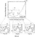
- FIG. 5c a graph 500 is shown illustrating a volume measurement of the backlash volume 90 over a period of time along with a bridgeland designed for three separate times T1, T2, T3.
- T1 corresponds to the time when two contact points 92, 94 first exist and T3 corresponds to the final time when two contact points 92, 94 exist. Therefore the backlash volume 90 only exists between times T1 and T3 (during period PI).
- FIG. 5c-1 shows a bridgeland 100 design that closes the backlash volume 90 to the high pressure side 204 and opens the backlash volume 90 to the low pressure side 202 at time T1.
- FIG. 5c-2 shows a bridgeland 100 design that closes the backlash volume 90 to the high pressure side 204 and opens the backlash volume 90 to the low pressure side 202 at time T2.
- FIG. 5c-3 shows a bridgeland 100 design that closes the backlash volume 90 to the high pressure side 204 and opens the backlash volume 90 to the low pressure side 202 at time T3.
- the bridgeland 100 designs showing in FIG. 5c simultaneously close and open the backlash volume 90, it is understood that the opening of the backlash volume 90 may occur before the closing of the backlash volume 90, or the closing of the backlash volume 90 may occur before the opening of the backlash volume.
- FIGs. 5c-1 , 5c-2, and 5c-3 show that the location (timing) of the bridgeland 100 relative to the gear teeth 74 and backlash volume 90 may be changed while still meeting the shape requirements discussed above in regard to FIG. 5b .
- the bridgeland 100 design in FIG. 5c-1 may be susceptible to pressure spikes since it is located on the bearing such that the sealing (closing and opening) of the backlash volume 90 occurs when the volume measurement of the backlash volume 90 is decreasing.
- the bridgeland 100 design in FIG. 5c-3 may be susceptible to cavitation since it is located on the bearing such that the sealing (closing and opening) of the backlash volume 90 occurs when the volume measurement of the backlash volume 90 is increasing.
- the volume measurement of the backlash volume 90 is decreasing for period P2, after which the volume measurement starts to increase again.
- FIG. 5c-2 shows the optimal timing, when sealing (closing and opening) of the backlash volume 90 occurs about when the rate of change of volume measurement of the backlash volume 90 is equal to zero.
- the volume of the backlash volume 90 decreases from time T1 to time T2 and then the volume of the backlash volume 90 increases from time T2 to time T3.
- the rate of change of the volume of the backlash volume 90 is about zero.
- the bridgeland 100 may be located to seal the backlash volume when a rate of change of a volume measurement of the backlash volume is decreasing or about equal to zero, thus at a time between T1 and T2 or about T2.
- the closing of the backlash volume 90 and the opening of the backlash volume 90 by the bridgeland 100 occurs when the rate of change of the volume measurement of the backlash volume 90 is about equal to zero.
- the bridgeland 100 may be located to seal the backlash volume when a rate of change of a volume measurement of the backlash volume is decreasing, as shown by the second time period P2 between time T1 and T2.
- locating the bridgeland 100 to seal at T2 or any time during the second time period P2 prevents the volume of the backlash volume 90 is increasing, which reduces the amount of cavitation.
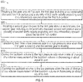
- FIG. 6 shows a flow chart of method 600 of reducing cavitation during fluid gear pump operation, in accordance with an embodiment of the disclosure.
- a first gear 56 is rotated around first axis 50.
- the first gear 56 includes a concentrically disposed first hub portion 72a and a plurality of first teeth radially projecting and circumferentially spaced about the first hub portion 72a.
- a second gear 60 coupled to the first gear 56 is rotated about a second axis.
- the second gear 60 includes a concentrically disposed second hub portion and a plurality of second teeth radially projecting and circumferentially spaced about the second hub portion.
- the plurality of first teeth 74a, 74b engage the plurality of second teeth 74c, 74d to create a backlash volume 90 interposed between the plurality of first teeth 74a, 74b and plurality of second teeth 74c, 74d when rotating.
- fluid is transferred from a low pressure side 202 to a high pressure side 204 when the first gear 56 is rotating and the second gear 60 is rotating.
- the fluid gets captured in the gear teeth 74 and is transferred from the low pressure side 202 to the high pressure side 204 as shown by arrow 256 and arrow 260 in FIG. 5a .
- the backlash volume 90 closes to the high pressure side 204 when a rate of change of a volume measurement of the backlash volume 90 is decreasing or about equal to zero.
- the backlash volume 90 opens to the low pressure 202 when the rate of change of the volume measurement of the backlash volume 90 is decreasing or about equal to zero.
- by opening and closing the backlash volume when the rate of change of a volume measurement of the backlash volume 90 is about equal to zero helps prevent cavitation bubbles from occurring by avoiding the drastic changes in pressure that result from significant volume changes under sealed conditions.
Landscapes
- Engineering & Computer Science (AREA)
- Mechanical Engineering (AREA)
- General Engineering & Computer Science (AREA)
- Rotary Pumps (AREA)
Abstract
Description
- The subject matter disclosed herein generally relates to the field of gear pumps, and more particularly to an apparatus and method for reducing cavitation in gear pumps.
- In one example of a gear pump, aircraft gas turbine engines receive pressurized fuel from gear-type fuel pumps. The gear pump typically performs over a wide operational speed range while providing needed fuel flows and pressures for various engine performance functions.
- Gear pumps often comprise two coupled gears of similar configuration and size that mesh with each other inside an enclosed gear housing. A drive gear may be connected rigidly to a drive shaft. As the drive gear rotates, it meshes with a driven gear thus rotating the driven gear. As the gears rotate within the housing, fluid is transferred from an inlet to an outlet of the gear pump. Typically, the drive gear carries the full load of the gear pump drive or input shaft. The two gears may operate at high loads and high pressures, which may stress the gear teeth.
- For given gear sizes the volume of fluid pumped through the gear pump may partially depend on the geometry of the tooth (e.g., depth, profile, etc.), the tooth count, and the width of the gear. Larger volumetric output may be achieved when lower gear tooth counts with large working tooth depths and face width are used. Alternatively, higher volumetric output may be achieved with higher rotational speed of the pump. Most gear pumps have gears with about ten to sixteen teeth. As the gears rotate, individual parcels of fluid are released between the teeth to the outlet. A common problem with more traditional gear pumps operating at high rotational speeds is cavitation erosion of the surfaces of the gear teeth and bearings. Cavitation erosion results in pitting of surfaces of the gear teeth that may eventually result in degraded pump volumetric capacity and affect pump operability and durability.
- According to one embodiment, a fluid gear pump is provided. The fluid gear pump comprises: a first gear constructed and arranged to rotate about a first axis, the first gear including a concentrically disposed first hub portion and a plurality of first teeth radially projecting and circumferentially spaced about the first hub portion; a second gear operably coupled to the first gear for rotation about a second axis, the second gear including a concentrically disposed second hub portion and a plurality of second teeth radially projecting and circumferentially spaced about the second hub portion, wherein at a time in operation the plurality of first teeth and the plurality of second teeth contact at first contact point and a second contact point to create a backlash volume interposed between the first contact point and the second contact point; a first bearing abutting and coaxial to the first hub portion; a second bearing abutting and coaxial to the second hub portion; and a bridgeland connecting the first bearing to the second bearing, the bridgeland being configured to separate a low pressure side of the fluid gear pump from a high pressure side of the fluid gear pump and periodically seal fluid within the backlash volume in a direction parallel with the first axis; wherein the bridgeland is substantially shaped to follow a curvature of the teeth creating the backlash volume without intersecting a line of action from the first contact point to the second contact point.
- In addition to one or more of the features described above, or as an alternative, further embodiments may include where the plurality of first teeth include a first leading tooth and a first trailing tooth adjacent to the first leading tooth; the plurality of second teeth include a second leading tooth and a second trailing tooth adjacent to the second leading tooth; the first contact point is between the first leading tooth and the second leading tooth; and the second contact point is between the first trailing tooth and the second trailing tooth.
- In addition to one or more of the features described above, or as an alternative, further embodiments may include where the bridgeland further comprises: a first side extending from the second bearing to the first bearing, the first side including: a first segment substantially following a curvature of the second leading tooth extending from the second bearing to the first contact point, a second segment is substantially parallel with the line of action extending from the first contact point until overlapping a curvature of the first leading tooth, and a third segment substantially following a curvature of the first leading tooth from the second segment to the first bearing; and a second side extending from the first bearing to the second bearing, the second side including: a first segment substantially following a curvature of the first trailing tooth extending from the first bearing to the second contact point, a second segment is substantially parallel with the line of action extending from the second contact point until overlapping a curvature of the second trailing tooth, and a third segment substantially following the curvature of the second trailing tooth from the second segment of the second side to the second bearing.
- In addition to one or more of the features described above, or as an alternative, further embodiments may include where the first leading tooth in operation loses contact with the second leading tooth at the first contact point when a rate of change of a volume measurement of the backlash volume is decreasing or about equal to zero.
- In addition to one or more of the features described above, or as an alternative, further embodiments may include where the first trailing tooth in operation contacts with the second trailing tooth at the second contact point when a rate of change of a volume measurement of the backlash volume is decreasing or about equal to zero.
- In addition to one or more of the features described above, or as an alternative, further embodiments may include where the bridgeland is located such that the backlash volume closes to the high pressure side and opens to the low pressure side when a rate of change of a volume measurement of the backlash volume is decreasing or about equal to zero.
- In addition to one or more of the features described above, or as an alternative, further embodiments may include where the fluid gear pump is a fuel pump.
- In addition to one or more of the features described above, or as an alternative, further embodiments may include where the first gear is a driving gear and the second gear is a driven gear.
- According to another embodiment, a fluid gear pump is provided. The fluid gear pump comprising: a first gear constructed and arranged to rotate about a first axis, the first gear including a concentrically disposed first hub portion and a plurality of first teeth radially projecting and circumferentially spaced about the first hub portion; a second gear operably coupled to the first gear for rotation about a second axis, the second gear including a concentrically disposed second hub portion and a plurality of second teeth radially projecting and circumferentially spaced about the second hub portion, wherein at a time in operation the plurality of first teeth and the plurality of second teeth contact at first contact point and a second contact point to create a backlash volume interposed between the first contact point and the second contact point; a first bearing abutting and coaxial to the first hub portion; a second bearing abutting and coaxial to the second hub portion; and a bridgeland connecting the first bearing to the second bearing, the bridgeland being configured to separate a low pressure side of the fluid gear pump from a high pressure side of the fluid gear pump and periodically seal fluid within the backlash volume in a direction parallel with the first axis; wherein the bridgeland is located such that the backlash volume closes to the high pressure side and opens to the low pressure side when a rate of change of a volume measurement of the backlash volume is decreasing or about equal to zero.
- In addition to one or more of the features described above, or as an alternative, further embodiments may include where the bridgeland is substantially shaped to follow a curvature of the teeth creating the backlash volume without intersecting a line of action from the first contact point to the second contact point.
- In addition to one or more of the features described above, or as an alternative, further embodiments may include where the plurality of first teeth include a first leading tooth and a first trailing tooth adjacent to the first leading tooth; the plurality of second teeth include a second leading tooth and a second trailing tooth adjacent to the second leading tooth; the first contact point is between the first leading tooth and the second leading tooth; and the second contact point is between the first trailing tooth and the second trailing tooth.
- In addition to one or more of the features described above, or as an alternative, further embodiments may include where the bridgeland further comprises: a first side extending from the second bearing to the first bearing, the first side including: a first segment substantially following a curvature of the second leading tooth extending from the second bearing to the first contact point, a second segment is substantially parallel with the line of action extending from the first contact point until overlapping a curvature of the first leading tooth, and a third segment substantially following a curvature of the first leading tooth from the second segment to the first bearing; and a second side extending from the first bearing to the second bearing, the second side including: a first segment substantially following a curvature of the first trailing tooth extending from the first bearing to the second contact point, a second segment is substantially parallel with the line of action extending from the second contact point until overlapping a curvature of the second trailing tooth, and a third segment substantially following the curvature of the second trailing tooth from the second segment of the second side to the second bearing.
- In addition to one or more of the features described above, or as an alternative, further embodiments may include where the first leading tooth in operation loses contact with the second leading tooth at the first contact point when a rate of change of a volume measurement of the backlash volume is decreasing or about equal to zero.
- In addition to one or more of the features described above, or as an alternative, further embodiments may include where the first trailing tooth in operation contacts with the second trailing tooth at the second contact point when a rate of change of a volume measurement of the backlash volume is decreasing or about equal to zero.
- In addition to one or more of the features described above, or as an alternative, further embodiments may include where the fluid gear pump is a fuel pump.
- In addition to one or more of the features described above, or as an alternative, further embodiments may include where the first gear is a driving gear and the second gear is a driven gear.
- According to another embodiment, a method of reducing cavitation during fluid gear pump operation is provided. The method comprising: rotating a first gear around first axis, the first gear including a concentrically disposed first hub portion and a plurality of first teeth radially projecting and circumferentially spaced about the first hub portion; rotating a second gear coupled to the first gear about a second axis, the second gear including a concentrically disposed second hub portion and a plurality of second teeth radially projecting and circumferentially spaced about the second hub portion, wherein the plurality of first teeth engage the plurality of second teeth to create a backlash volume interposed between the plurality of first teeth and plurality of second teeth when rotating; transferring fluid from a low pressure side to a high pressure side when the first gear is rotating and the second gear is rotating; closing the backlash volume to the high pressure side when a rate of change of a volume measurement of the backlash volume is decreasing or about equal to zero; and opening the backlash volume to the low pressure when the rate of change of the volume measurement of the backlash volume is decreasing or about equal to zero.
- In addition to one or more of the features described above, or as an alternative, further embodiments may include where the backlash volume is closed using a bridgeland.
- In addition to one or more of the features described above, or as an alternative, further embodiments may include where the backlash volume is opened using a bridgeland.
- Technical effects of embodiments of the present disclosure include shaping and locating the bridgeland to reduce cavitation, while also timing the gear teeth meshing to further control cavitation.
- The foregoing features and elements may be combined in various combinations without exclusivity, unless expressly indicated otherwise. These features and elements as well as the operation thereof will become more apparent in light of the following description and the accompanying drawings. It should be understood, however, that the following description and drawings are intended to be illustrative and explanatory in nature and non-limiting.
- The following descriptions should not be considered limiting in any way. With reference to the accompanying drawings, like elements are numbered alike:
-
FIG. 1 illustrates a schematic of an aircraft fuel system as one, non-limiting, example of an application of a gear pump of the present disclosure; -
FIG. 2 illustrates a perspective view of the gear pump with a housing removed to show internal detail; -
FIG. 3 illustrates a side view of coupled gears and associated bearings of the gear pump; -
FIG. 4 illustrates a partial perspective view of one of the coupled gears; -
FIG. 5a ,5b , and5c illustrate a schematic view of coupled gears with a bridgeland overlaid and a backlash volume overlaid, in accordance with an embodiment of the disclosure; and -
FIG. 6 illustrates a flow diagram illustrating a method of reducing cavitation during fluid gear pump operation, in accordance with an embodiment of the disclosure. - A detailed description of one or more embodiments of the disclosed apparatus and method are presented herein by way of exemplification and not limitation with reference to the Figures.
- Various embodiments of the present disclosure are related to the reduction of fluid cavitation within gear pumps. Aircraft engine high pressure fuel pumps typically use a pair of involute gears to generate fuel pressure for the burner injectors. These gears are enclosed in a housing within which they are supported by bearings. In the vicinity of the gear meshing region these bearings form a bridgeland that separates the high and low pressure regions and maintains high pump efficiency. A pump of this description experiences significant pressure oscillations that may lead to the formation and subsequent collapse of cavitation bubbles that may cause material damage. The gears, supporting bearings, and enclosing housing are all susceptible to cavitation damage that results in a deterioration of pump performance and can significantly reduce the useable life of these components. This is particularly relevant in the region of the bridgeland which amplifies local pressure oscillations through a periodic sealing of the trapped volume between the interlocking gear teeth (backlash volume). The geometrical features of the bridgeland sealing surface have a strong influence on cavitation damage. To address these issues some designs introduce leaks through the gear intermeshing region that mitigate the magnitude of local pressure oscillations at the expense of reduced pump efficiency.
- Embodiments disclosed herein seek to address a method of designing the bridgeland geometry to seal the pump high-pressure discharge from the low-pressure inlet in such a way that cavitation damages are minimized and/or eliminated without relying on undesirable leaks. Advantageously, this methodology will (i) reduce formation of bubbles due to cavitation and reduce the severity of their collapse, thus minimizing cavitation damage; (ii) optimize the fluid filling and venting in the gear meshing region such that erosion due to fluid dynamical processes is minimized, and (iii) ensure that there is no direct leak between high and low pressure sides so that pump efficiency is not compromised.
- Referring to
FIG. 1 , one embodiment of afuel system 20 of the present disclosure is illustrated. Thefuel system 20 may be an aircraft fuel system and may include afuel supply line 22 that may flow liquid fuel from afuel tank 24 tofuel nozzles 26 of an engine (not shown). Afuel bypass line 28 may be arranged to divert fuel from thesupply line 22 and back to thefuel tank 24. Various fuel system components may interpose thefuel supply line 22 and may include a lowpressure fuel pump 30, aheat exchanger 32, afuel filter 34, a highpressure fuel pump 36, ametering valve 38, a high pressurefuel shutoff valve 40, ascreen 42, afuel flow sensor 44, and a fueltank shutoff valve 45. The lowpressure fuel pump 30 may be located downstream of thefuel tank 24. Theheat exchanger 32 may be located downstream of the lowpressure fuel pump 30. Thefuel filter 34 may be located downstream of theheat exchanger 32. The highpressure fuel pump 36 may be located downstream of thefuel filter 34 and upstream of thefuel bypass line 28. Themetering valve 38 may be located downstream from thebypass line 28. The high pressurefuel shutoff valve 40 may be located downstream from thebypass line 28. Thescreen 42 may be located downstream from the high pressurefuel shutoff valve 40, and thefuel flow sensor 44 may be located downstream from thescreen 42. It is further contemplated and understood that other component configurations of a fuel system are applicable and may further include additional sensors, valves and other components. - The
heat exchanger 32 may be adapted to use the flowing fuel as a heat sink to cool other liquids flowing from any variety of auxiliary systems of an aircraft and/or the engine. For example, theheat exchanger 32 may transfer heat from an oil and to the fuel. The oil may be used to lubricate any variety of auxiliary components including, for example, a gear box (not shown) of the engine. Such a transfer of heat may elevate the temperature of the fuel which may make the highpressure fuel pump 36 more prone to cavitation. - Referring to
FIGS. 2 and3 , one non-limiting example of the highpressure fuel pump 36 is illustrated as a gear pump with a housing removed to show internal detail. Thegear pump 36 may be a dual stage pump and may include an fuel centrifugalboost pump housing 46, aninput drive shaft 48 constructed for rotation about afirst axis 50, acoupling shaft 52 constructed for rotation about asecond axis 54, adrive gear 56 with associatedbearings 58, a drivengear 60 with associatedbearings 62, amotive drive gear 64 and a motive drivengear 66 configured for rotation about athird axis 68. Theaxis drive shaft 48 may attach to an engine gear box (not shown). Thedrive gear 56 is engaged and concentrically disposed to thedrive shaft 48. The drivengear 60 andmotive drive gear 64 are engaged and concentrically disposed to thecoupling shaft 52. The drive and drivengears motive drive gear 64 and motive drivengear 66 are rotationally coupled to one another for the continued pumping of the fuel as a second stage. It is further contemplated and understood that many other types of gear pumps may be applicable to the present disclosure. For example, the gear pump may be a single stage gear pump, and/or thedrive shaft 48 may be attached to any other device capable of rotating the drive shaft 48 (e.g., electric motor). - The
bearings common carrier 70 that generally resembles a figure eight. A gear bearing face geometry, known in the art as abridgeland 100 may be sculpted to minimize cavitation and pressure ripple that may deteriorate the integrity of the pump components, discussed further below. Thebridgeland 100 separates alow pressure side 202 and a high pressure side 204 (seeFIGs. 5a-5c ) of thepump 36 and periodically provides sealing of a backlash volume 90 (seeFIGs. 5a-5c ) in a direction parallel with thefirst axis 50 and/or thesecond axis 54. - In operation, the
gear pump 36 is capable of providing fuel at a wide range of fuel volume/quantity and pressures for various engine performance functions. The engine gearbox provides rotational power to thedrive shaft 48 which, in-turn, rotates theconnected drive gear 56. Thedrive gear 56 then drives (i.e., rotates) the drivengear 60 that rotates thecoupling shaft 52. Rotation of thecoupling shaft 52 rotates themotive drive gear 64 that, in-turn, rotates the motive drivengear 66. - Referring to
FIG. 4 , each of thegears hub portion 72 and a plurality ofteeth 74 that may both span axially between two opposite facingsidewalls sidewall hub portion 72 may be disclike and projects radially outward from therespective shafts axis continuous face 80 generally carried by thehub portion 72. Theface 80 may generally be cylindrical. The plurality ofteeth 74 project radially outward from theface 80 of thehub portion 72 and are circumferentially spaced about thehub portion 72. Thegears - Referring to
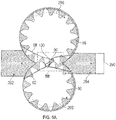
FIGs. 5a ,5b , and5c with continued references toFIGs. 1-4 . For the description ofFIGs. 5a ,5b , and5c , thedrive gear 56 may be referred to as afirst gear 56 having a plurality of first teeth including a firstleading tooth 74a and a first trailing tooth 74b. As seen inFIG. 5b , the first trailing tooth 74b is adjacent the firstleading tooth 74a on thefirst gear 56. The firstleading tooth 74a advances ahead in rotation of the first trailing tooth 74b. Also for the description ofFIGs. 5a and5b , the drivengear 60 may be referred to as asecond gear 60 having a plurality of second teeth including a secondleading tooth 74c and asecond trailing tooth 74d. As seen inFIG. 5b , the second trailingtooth 74d is adjacent the secondleading tooth 74c on thesecond gear 60. The secondleading tooth 74c advance in rotation ahead of the second trailingtooth 74d. - As seen in
FIG. 5a , thefirst gear 56 is rotating in a clockwise direction and driving thesecond gear 60 to rotate in a counter-clockwise direction. The clockwise rotation of thefirst gear 56 transfers fluid around thefirst gear 56 as shown byarrow 256 and counter-clockwise rotation of thesecond gear 60 transfers fluid around thesecond gear 60 as shown byarrow 260, thus transferring fluid from alow pressure side 202 to ahigh pressure side 204. Located on the high pressure side, downstream of this fluid flow, afluid regulating device 290 may assist in building up the pressure on thehigh pressure side 204. When thefirst gear 56 and thesecond gear 60 begin to mesh, fluid is pushed out from between the gears towards the high pressure side, however a small amount of fluid may remain in thebacklash volume 90, discussed further below. The fluid in thebacklash volume 90 is transported back over to thelow pressure side 202 afterfirst gear 56 andsecond gear 60 disengage. - As seen in
FIG. 5b , at a time in operation the plurality offirst teeth 74a, 74b and the plurality ofsecond teeth first contact point 92 and asecond contact point 94 to create abacklash volume 90 interposed between thefirst contact point 92 and thesecond contact point 94. In the embodiment ofFIG. 5b , at that time in operation the firstleading tooth 74a is in contact with the secondleading tooth 74c at thefirst contact point 92 and the first trailing tooth 74b is in contact with the second trailingtooth 74d to create thebacklash volume 90 interposed between thefirst contact point 92 and thesecond contact point 94. As seen inFIG. 5b , a line ofaction 96 exists from thefirst contact point 92 to thesecond contact point 94. The line ofaction 96 shows the direction of force passing from thefirst gear 56 to thesecond gear 60 at that moment in time. - Also seen in
FIG. 5b overlaid over thegears first bearing 58 and asecond bearing 62. Thefirst bearing 58 is abutting and coaxial to the first hub portion (not shown) of thefirst gear 56. Thesecond bearing 62 is abutting and coaxial to the second hub portion (not shown) of thesecond gear 60. Thefirst bearing 58 is connected to thesecond bearing 62 through abridgeland 100. Thebridgeland 100 is configured to separate alow pressure side 202 of the fluid gear pump 36 from ahigh pressure side 204 of thefluid gear pump 36 and periodically seal fluid within thebacklash volume 90 when the contacts points 92, 94 are in contact. Thebridgeland 100 provides sealing a direction parallel with thefirst axis 50 and/or thesecond axis 54. Thebridgeland 100 is substantially shaped to follow a curvature of theteeth 74a-d creating thebacklash volume 90 without intersecting a line ofaction 96 from thefirst contact point 92 to thesecond contact point 94. Advantageously, shaping thebridgeland 100 to substantially follow the curvature of theteeth 74a-d allows for the efficient filling and evacuating of the backlash volume, thus optimizing the fluid filling and venting in the gear meshing region such that erosion due to fluid dynamical processes is minimized and/or reduced. - The
bridgeland 100 is composed of afirst side 110 and asecond side 120. Thefirst side 110 extends from thesecond bearing 62 to thefirst bearing 58. Thefirst side 110 may include threeconnected segments first segment 112 of thefirst side 110 substantially follows acurvature 174a of the secondleading tooth 74c extending from thesecond bearing 62 to thefirst contact point 92. Thesecond segment 114 of thefirst side 110 is substantially parallel with the line ofaction 96 extending from thefirst contact point 92 until overlapping acurvature 132 of the firstleading tooth 74a. Thethird segment 116 of the first side substantially follows acurvature 174b of the firstleading tooth 74a from thesecond segment 114 to thefirst bearing 58. - The
second side 120 extends from thefirst bearing 58 to thesecond bearing 62. Thesecond side 120 may also include threeconnected segments second side 120 substantially following acurvature 274a of the first trailing tooth 74b extending from thefirst bearing 58 to thesecond contact point 94. Thesecond segment 124 of thesecond side 120 is substantially parallel with the line ofaction 96 extending from thesecond contact point 94 until overlapping acurvature 134 of the second trailingtooth 74d. Thethird segment 126 of thesecond side 120 substantially follows thecurvature 274b of the second trailingtooth 74d from thesecond segment 124 of thesecond side 120 to thesecond bearing 62. - During operation of the
fuel system 20 as one example, aircraft fuel may be heated by theheat exchanger 32 to temperatures as high as about 300°F (149°C) at pressures that may reach 300 psi (2.07 MPa). This heated fuel may enter thehigh pressure pump 36 and is further increased in pressure (at a controlled flow) via the un-meshing and re-meshing of theteeth 74 of the coupled gears 56, 60 and or gears 64, 66. The shape of thebridgeland 100 may help minimize cavitation and pressure ripple that may occur when the fuel flashes into a vapor phase during meshing of theteeth 74 and the resulting vapor bubbles collapse onto the gear and bearing surfaces as the pressure rises. Benefits of the present disclosure include a reduction or elimination of cavitation near a surface of thegear teeth 74 and/or bearing surfaces through thebridgeland 100 shaping and location with respect to thebacklash volume 90. - In a first embodiment, the first
leading tooth 74a in operation contacts the secondleading tooth 74c at thefirst contact point 92 about simultaneously to when the first trailing tooth 74b contacts the second trailingtooth 74d at thesecond contact point 94. In a second embodiment, the first trailing tooth 74b in operation contacts the second trailingtooth 74d at thesecond contact point 94 prior to the firstleading tooth 74a loosing contact with the secondleading tooth 74c at thefirst contact point 92. The presence of twocontact points backlash volume 90. In the first and second embodiments described immediately prior, thebridgeland 100 defines when thebacklash volume 90 closes to thehigh pressure side 204 and opens to thelow pressure side 202. The present disclosure describes abridgeland 100 that closes thebacklash volume 90 to thehigh pressure side 204 before opening thebacklash volume 90 to thelow pressure side 202. Advantageously timing the opening of thebacklash volume 90 to thelow pressure side 202 and the closing of thebacklash volume 90 tohigh pressure side 204 in such a way that there is no direct communication between thesides - In an embodiment, the first trailing tooth 74b in operation contacts with the second trailing
tooth 74d at thesecond contact point 94 about simultaneous to the firstleading tooth 74a loosing contact with the secondleading tooth 74c at thefirst contact point 92, thus minimizing the time period that thebacklash volume 90 is sealed. Advantageously, minimizing the time period that thebacklash volume 90 is sealed minimizes the period when low pressures are experienced and cavitation takes place. - In an embodiment, the bridgeland 100 location/timing causes the
backlash volume 90 to close to thehigh pressure side 204 and open to thelow pressure side 202 when a rate of change of a volume measurement of thebacklash volume 90 is about equal to zero. Advantageously, linking the timing for sealing (closing and opening) of thebacklash volume 90 to the magnitude and rate of change of volume measurement of thebacklash volume 90 minimizes the magnitude of pressure oscillations in thebacklash volume 90 and the formation and collapse of cavitation bubbles. This volume measurement initially decreases and then increases during the gear interlocking period thus experiencing a minimum at one point (i.e. a rate of change equal to about zero). In an embodiment, the opening and closing is designed to occur near this minimum when rate of change is close to zero. It is noted that sealing the volume during the period when thebacklash volume 90 is decreasing (i.e. prior to the minimum) may provide additional benefits from a cavitation perspective since no low pressures can be experienced and no cavitation will be manifested. However, due to the fact that the liquid in thebacklash volume 90 is being compressed during this period, bridgeland 100 designs that attempt to exploit this feature may be prone to pressure spikes. Thus, it is advantageous to avoid locating thebridgeland 100 in an area overlaying thegear teeth 74 such that thebacklash volume 90 closes to thehigh pressure side 204 and opens to thelow pressure side 202 where the volume measurement of thebacklash volume 90 is decreasing. It is advantageous to locate thebridgeland 100 overlaying thegear teeth 74 in such a way that it can seal and unseal thebacklash volume 90 near a region where the volume measurement of thebacklash volume 90 is the smallest and experiences smallest variations. - As seen in
FIG. 5c agraph 500 is shown illustrating a volume measurement of thebacklash volume 90 over a period of time along with a bridgeland designed for three separate times T1, T2, T3. T1 corresponds to the time when twocontact points contact points backlash volume 90 only exists between times T1 and T3 (during period PI).FIG. 5c-1 shows abridgeland 100 design that closes thebacklash volume 90 to thehigh pressure side 204 and opens thebacklash volume 90 to thelow pressure side 202 at time T1.FIG. 5c-2 shows abridgeland 100 design that closes thebacklash volume 90 to thehigh pressure side 204 and opens thebacklash volume 90 to thelow pressure side 202 at time T2.FIG. 5c-3 shows abridgeland 100 design that closes thebacklash volume 90 to thehigh pressure side 204 and opens thebacklash volume 90 to thelow pressure side 202 at time T3. Although thebridgeland 100 designs showing inFIG. 5c simultaneously close and open thebacklash volume 90, it is understood that the opening of thebacklash volume 90 may occur before the closing of thebacklash volume 90, or the closing of thebacklash volume 90 may occur before the opening of the backlash volume. It is advantageous to close thebacklash volume 90 to thehigh pressure side 204 before opening thebacklash volume 90 to thelow pressure side 202 to avoid leaks and decreases in pump performance.FIGs. 5c-1 ,5c-2, and 5c-3 , show that the location (timing) of thebridgeland 100 relative to thegear teeth 74 andbacklash volume 90 may be changed while still meeting the shape requirements discussed above in regard toFIG. 5b . - The
bridgeland 100 design inFIG. 5c-1 , may be susceptible to pressure spikes since it is located on the bearing such that the sealing (closing and opening) of thebacklash volume 90 occurs when the volume measurement of thebacklash volume 90 is decreasing. Thebridgeland 100 design inFIG. 5c-3 may be susceptible to cavitation since it is located on the bearing such that the sealing (closing and opening) of thebacklash volume 90 occurs when the volume measurement of thebacklash volume 90 is increasing. The volume measurement of thebacklash volume 90 is decreasing for period P2, after which the volume measurement starts to increase again.FIG. 5c-2 shows the optimal timing, when sealing (closing and opening) of thebacklash volume 90 occurs about when the rate of change of volume measurement of thebacklash volume 90 is equal to zero. - As seen in
FIG. 5C , the volume of thebacklash volume 90 decreases from time T1 to time T2 and then the volume of thebacklash volume 90 increases from time T2 to time T3. At time T2 the rate of change of the volume of thebacklash volume 90 is about zero. In an embodiment, thebridgeland 100 may be located to seal the backlash volume when a rate of change of a volume measurement of the backlash volume is decreasing or about equal to zero, thus at a time between T1 and T2 or about T2. Thus, the closing of thebacklash volume 90 and the opening of thebacklash volume 90 by thebridgeland 100 occurs when the rate of change of the volume measurement of thebacklash volume 90 is about equal to zero. In another embodiment, thebridgeland 100 may be located to seal the backlash volume when a rate of change of a volume measurement of the backlash volume is decreasing, as shown by the second time period P2 between time T1 and T2. Advantageously, locating thebridgeland 100 to seal at T2 or any time during the second time period P2 prevents the volume of thebacklash volume 90 is increasing, which reduces the amount of cavitation. - Referring now to
FIG. 6 , with continued reference toFIGs. 1-5 .FIG. 6 shows a flow chart ofmethod 600 of reducing cavitation during fluid gear pump operation, in accordance with an embodiment of the disclosure. Atblock 604, afirst gear 56 is rotated aroundfirst axis 50. Thefirst gear 56 includes a concentrically disposed first hub portion 72a and a plurality of first teeth radially projecting and circumferentially spaced about the first hub portion 72a. Atblock 606, asecond gear 60 coupled to thefirst gear 56 is rotated about a second axis. Thesecond gear 60 includes a concentrically disposed second hub portion and a plurality of second teeth radially projecting and circumferentially spaced about the second hub portion. The plurality offirst teeth 74a, 74b engage the plurality ofsecond teeth backlash volume 90 interposed between the plurality offirst teeth 74a, 74b and plurality ofsecond teeth - At
block 608, fluid is transferred from alow pressure side 202 to ahigh pressure side 204 when thefirst gear 56 is rotating and thesecond gear 60 is rotating. The fluid gets captured in thegear teeth 74 and is transferred from thelow pressure side 202 to thehigh pressure side 204 as shown byarrow 256 andarrow 260 inFIG. 5a . Atblock 610, thebacklash volume 90 closes to thehigh pressure side 204 when a rate of change of a volume measurement of thebacklash volume 90 is decreasing or about equal to zero. Atblock 612, thebacklash volume 90 opens to thelow pressure 202 when the rate of change of the volume measurement of thebacklash volume 90 is decreasing or about equal to zero. Advantageously, by opening and closing the backlash volume when the rate of change of a volume measurement of thebacklash volume 90 is about equal to zero helps prevent cavitation bubbles from occurring by avoiding the drastic changes in pressure that result from significant volume changes under sealed conditions. - While the above description has described the flow process of
FIG. 6 in a particular order, it should be appreciated that unless otherwise specifically required in the attached claims that the ordering of the steps may be varied. - The term "about" is intended to include the degree of error associated with measurement of the particular quantity based upon the equipment available at the time of filing the application. For example, "about" can include a range of ± 8% or 5%, or 2% of a given value.
- The terminology used herein is for the purpose of describing particular embodiments only and is not intended to be limiting of the present disclosure. As used herein, the singular forms "a", "an" and "the" are intended to include the plural forms as well, unless the context clearly indicates otherwise. It will be further understood that the terms "comprises" and/or "comprising," when used in this specification, specify the presence of stated features, integers, steps, operations, elements, and/or components, but do not preclude the presence or addition of one or more other features, integers, steps, operations, element components, and/or groups thereof.
- While the present disclosure has been described with reference to an exemplary embodiment or embodiments, it will be understood by those skilled in the art that various changes may be made and equivalents may be substituted for elements thereof without departing from the scope of the present disclosure. In addition, many modifications may be made to adapt a particular situation or material to the teachings of the present disclosure without departing from the essential scope thereof. Therefore, it is intended that the present disclosure not be limited to the particular embodiment disclosed as the best mode contemplated for carrying out this present disclosure, but that the present disclosure will include all embodiments falling within the scope of the claims.
Claims (15)
- A fluid gear pump comprising:a first gear (56) constructed and arranged to rotate about a first axis, the first gear including a concentrically disposed first hub portion (72) and a plurality of first teeth (74) radially projecting and circumferentially spaced about the first hub portion;a second gear (60) operably coupled to the first gear (56) for rotation about a second axis, the second gear including a concentrically disposed second hub portion (72) and a plurality of second teeth (74) radially projecting and circumferentially spaced about the second hub portion, wherein at a time in operation the plurality of first teeth and the plurality of second teeth contact at first contact point and a second contact point to create a backlash volume (90) interposed between the first contact point and the second contact point;a first bearing (58) abutting and coaxial to the first hub portion;
a second bearing (62) abutting and coaxial to the second hub portion; and
a bridgeland (100) connecting the first bearing (58) to the second bearing (62), the bridgeland being configured to separate a low pressure side of the fluid gear pump from a high pressure side of the fluid gear pump and periodically seal fluid within the backlash volume (90) in a direction parallel with the first axis;
wherein the bridgeland (100) is substantially shaped to follow a curvature of the teeth creating the backlash volume without intersecting a line of action from the first contact point to the second contact point. - The fluid gear pump set forth in claim 1, wherein:the plurality of first teeth include a first leading tooth (74a) and a first trailing tooth (74b) adjacent to the first leading tooth;the plurality of second teeth include a second leading tooth (74c) and a second trailing tooth (74d) adjacent to the second leading tooth;the first contact point is between the first leading tooth (74a) and the second leading tooth (74c); andthe second contact point is between the first trailing tooth (74b) and the second trailing tooth (74d).
- The fluid gear pump set forth in claim 2, wherein the bridgeland (100) further comprises:a first side (110) extending from the second bearing to the first bearing, the first side including: a first segment (112) substantially following a curvature of the second leading tooth extending from the second bearing to the first contact point, a second segment (114) is substantially parallel with the line of action extending from the first contact point until overlapping a curvature of the first leading tooth, and a third segment (116) substantially following a curvature of the first leading tooth from the second segment to the first bearing; anda second side (120) extending from the first bearing to the second bearing, the second side including: a first segment (122) substantially following a curvature of the first trailing tooth extending from the first bearing to the second contact point, a second segment (124) is substantially parallel with the line of action extending from the second contact point until overlapping a curvature of the second trailing tooth, and a third segment (126) substantially following the curvature of the second trailing tooth from the second segment of the second side to the second bearing.
- The fluid gear pump set forth in claim 2, wherein the first leading tooth (74a) in operation loses contact with the second leading tooth (74c) at the first contact point when a rate of change of a volume measurement of the backlash volume is decreasing or about equal to zero.
- The fluid gear pump set forth in claim 2, wherein the first trailing tooth (74b) in operation contacts with the second trailing tooth (74d) at the second contact point when a rate of change of a volume measurement of the backlash volume is decreasing or about equal to zero.
- The fluid gear pump set forth in claim 2, wherein the bridgeland (100) is located such that the backlash volume closes to the high pressure side and opens to the low pressure side when a rate of change of a volume measurement of the backlash volume is decreasing or about equal to zero.
- The fluid gear pump set forth in any preceding claim, wherein the fluid gear pump is a fuel pump.
- The fluid gear pump set forth in any preceding claim, wherein the first gear is a driving gear and the second gear is a driven gear.
- A fluid gear pump comprising:a first gear (56) constructed and arranged to rotate about a first axis, the first gear including a concentrically disposed first hub portion and a plurality of first (74) teeth radially projecting and circumferentially spaced about the first hub portion;a second gear (60) operably coupled to the first gear for rotation about a second axis, the second gear including a concentrically disposed second hub portion and a plurality of second teeth radially projecting and circumferentially spaced about the second hub portion, wherein at a time in operation the plurality of first teeth and the plurality of second teeth contact at first contact point and a second contact point to create a backlash volume interposed between the first contact point and the second contact point;a first bearing (58) abutting and coaxial to the first hub portion;
a second bearing (62) abutting and coaxial to the second hub portion; and
a bridgeland (100) connecting the first bearing to the second bearing, the bridgeland being configured to separate a low pressure side of the fluid gear pump from a high pressure side of the fluid gear pump and periodically seal fluid within the backlash volume in a direction parallel with the first axis;
wherein the bridgeland (100) is located such that the backlash volume closes to the high pressure side and opens to the low pressure side when a rate of change of a volume measurement of the backlash volume is decreasing or about equal to zero. - The fluid gear pump set forth in claim 9, wherein:
the bridgeland (100) is substantially shaped to follow a curvature of the teeth creating the backlash volume without intersecting a line of action from the first contact point to the second contact point. - The fluid gear pump set forth in claim 10, wherein:the plurality of first teeth (74) include a first leading tooth (74a) and a first trailing tooth (74b) adjacent to the first leading tooth;the plurality of second teeth include a second leading tooth (74c) and a second trailing tooth (74d) adjacent to the second leading tooth;the first contact point is between the first leading tooth (74a) and the second leading tooth (74c); andthe second contact point is between the first trailing tooth (74b) and the second trailing tooth (74d).
- The fluid gear pump set forth in claim 11, wherein the bridgeland (100) further comprises:a first side (110) extending from the second bearing to the first bearing, the first side including: a first segment substantially following a curvature of the second leading tooth extending from the second bearing to the first contact point, a second segment is substantially parallel with the line of action extending from the first contact point until overlapping a curvature of the first leading tooth, and a third segment substantially following a curvature of the first leading tooth from the second segment to the first bearing; anda second side (120) extending from the first bearing to the second bearing, the second side including: a first segment substantially following a curvature of the first trailing tooth extending from the first bearing to the second contact point, a second segment is substantially parallel with the line of action extending from the second contact point until overlapping a curvature of the second trailing tooth, and a third segment substantially following the curvature of the second trailing tooth from the second segment of the second side to the second bearing.
- The fluid gear pump set forth in claim 11, wherein the first leading tooth (74a) in operation loses contact with the second leading tooth (74c) at the first contact point when a rate of change of a volume measurement of the backlash volume is decreasing or about equal to zero.
- The fluid gear pump set forth in claim 11, wherein the first trailing tooth (74b) in operation contacts with the second trailing tooth (74d) at the second contact point when a rate of change of a volume measurement of the backlash volume is decreasing or about equal to zero.
- The fluid gear pump set forth in any of claims 9 to 14, wherein the fluid gear pump is a fuel pump.
Priority Applications (1)
| Application Number | Priority Date | Filing Date | Title |
|---|---|---|---|
| EP21169158.9A EP3882464B1 (en) | 2017-06-23 | 2018-06-25 | Gear pump with means for reduction of cavitation |
Applications Claiming Priority (1)
| Application Number | Priority Date | Filing Date | Title |
|---|---|---|---|
| US15/631,973 US10634135B2 (en) | 2017-06-23 | 2017-06-23 | Reduction of cavitation in gear pumps |
Related Child Applications (2)
| Application Number | Title | Priority Date | Filing Date |
|---|---|---|---|
| EP21169158.9A Division EP3882464B1 (en) | 2017-06-23 | 2018-06-25 | Gear pump with means for reduction of cavitation |
| EP21169158.9A Division-Into EP3882464B1 (en) | 2017-06-23 | 2018-06-25 | Gear pump with means for reduction of cavitation |
Publications (2)
| Publication Number | Publication Date |
|---|---|
| EP3418571A1 true EP3418571A1 (en) | 2018-12-26 |
| EP3418571B1 EP3418571B1 (en) | 2022-02-23 |
Family
ID=62778833
Family Applications (2)
| Application Number | Title | Priority Date | Filing Date |
|---|---|---|---|
| EP21169158.9A Active EP3882464B1 (en) | 2017-06-23 | 2018-06-25 | Gear pump with means for reduction of cavitation |
| EP18179640.0A Active EP3418571B1 (en) | 2017-06-23 | 2018-06-25 | Gear pump with means for reduction of cavitation |
Family Applications Before (1)
| Application Number | Title | Priority Date | Filing Date |
|---|---|---|---|
| EP21169158.9A Active EP3882464B1 (en) | 2017-06-23 | 2018-06-25 | Gear pump with means for reduction of cavitation |
Country Status (2)
| Country | Link |
|---|---|
| US (1) | US10634135B2 (en) |
| EP (2) | EP3882464B1 (en) |
Cited By (1)
| Publication number | Priority date | Publication date | Assignee | Title |
|---|---|---|---|---|
| WO2020178163A1 (en) * | 2019-03-02 | 2020-09-10 | Brose Fahrzeugteile SE & Co. Kommanditgesellschaft, Würzburg | Gear pump for venting trapped volume |
Families Citing this family (2)
| Publication number | Priority date | Publication date | Assignee | Title |
|---|---|---|---|---|
| US10941767B2 (en) * | 2018-03-29 | 2021-03-09 | Hamilton Sunstrand Corporation | Hybrid pump bearing for contamination resistance |
| EP4098876A4 (en) * | 2020-01-30 | 2023-11-01 | Shimadzu Corporation | Gear pump or gear motor |
Citations (3)
| Publication number | Priority date | Publication date | Assignee | Title |
|---|---|---|---|---|
| EP0769104B1 (en) * | 1994-07-07 | 1999-09-01 | David Brown Hydraulics Limited | Helical gear pump or motor |
| US20120219449A1 (en) * | 2011-02-25 | 2012-08-30 | Weishun Ni | Bearing face geometry for gear pump |
| US20150147211A1 (en) * | 2013-11-26 | 2015-05-28 | Woodward, Inc. | Gear Pump Bearing Dam |
Family Cites Families (6)
| Publication number | Priority date | Publication date | Assignee | Title |
|---|---|---|---|---|
| US1129090A (en) * | 1914-04-08 | 1915-02-23 | American La France Fire Engine Company Inc | Gear-pump. |
| US3145661A (en) * | 1962-12-19 | 1964-08-25 | New York Air Brake Co | Pump |
| WO2015131057A2 (en) * | 2014-02-28 | 2015-09-03 | Purdue Research Foundation | Variable delivery external gear machine |
| US9874208B2 (en) * | 2015-01-21 | 2018-01-23 | Hamilton Sunstrand Corporation | Bearing faces with fluid channels for gear pumps |
| US10563653B2 (en) | 2016-01-12 | 2020-02-18 | Hamilton Sundstrand Corporation | Gear pump |
| US10260501B2 (en) * | 2016-08-16 | 2019-04-16 | Hamilton Sundstrand Corporation | Bearing structures for gear pumps |
-
2017
- 2017-06-23 US US15/631,973 patent/US10634135B2/en active Active
-
2018
- 2018-06-25 EP EP21169158.9A patent/EP3882464B1/en active Active
- 2018-06-25 EP EP18179640.0A patent/EP3418571B1/en active Active
Patent Citations (3)
| Publication number | Priority date | Publication date | Assignee | Title |
|---|---|---|---|---|
| EP0769104B1 (en) * | 1994-07-07 | 1999-09-01 | David Brown Hydraulics Limited | Helical gear pump or motor |
| US20120219449A1 (en) * | 2011-02-25 | 2012-08-30 | Weishun Ni | Bearing face geometry for gear pump |
| US20150147211A1 (en) * | 2013-11-26 | 2015-05-28 | Woodward, Inc. | Gear Pump Bearing Dam |
Cited By (2)
| Publication number | Priority date | Publication date | Assignee | Title |
|---|---|---|---|---|
| WO2020178163A1 (en) * | 2019-03-02 | 2020-09-10 | Brose Fahrzeugteile SE & Co. Kommanditgesellschaft, Würzburg | Gear pump for venting trapped volume |
| US11028847B2 (en) | 2019-03-02 | 2021-06-08 | Brose Fahrzeugteile GmbH & Co. Kommanditgesellschaft, Würzburg | Gear pump for venting trapped volume |
Also Published As
| Publication number | Publication date |
|---|---|
| EP3882464B1 (en) | 2024-05-01 |
| US20180372091A1 (en) | 2018-12-27 |
| EP3418571B1 (en) | 2022-02-23 |
| US10634135B2 (en) | 2020-04-28 |
| EP3882464A1 (en) | 2021-09-22 |
Similar Documents
| Publication | Publication Date | Title |
|---|---|---|
| EP3882464B1 (en) | Gear pump with means for reduction of cavitation | |
| CN100532841C (en) | Variable output rotor pump | |
| RU2700840C2 (en) | Pump combined with two primary drives driven independently from each other (embodiments), and method of pump operation (embodiments) | |
| US9829002B2 (en) | Pump system for high pressure application | |
| EP2672118B1 (en) | Gear pump, pumping apparatus including the same, and aircraft fuel system including gear pump | |
| EP1589226A1 (en) | Pump assembly | |
| US8672657B2 (en) | Double gear pump with improved bearings | |
| US10677095B2 (en) | Lubrication device for a turbine engine | |
| CN106168166A (en) | Lubricating system for turbogenerator | |
| US20160003250A1 (en) | Axial seal for roots-style supercharger | |
| EP3219988B1 (en) | Gear pump with passageways in gear teeth | |
| CN103998785B (en) | Internal-gear pump | |
| EP3193019B1 (en) | A gear pump | |
| US10808695B2 (en) | Reduction of cavitation in fuel pumps | |
| EP3495661A1 (en) | Reduction of cavitation damages in fuel pumps | |
| CN103541897B (en) | Case outer support rotary piston pump | |
| KR101492936B1 (en) | Oil Pump | |
| RU2511848C1 (en) | Adjustable gear-type pump | |
| CN201650722U (en) | High viscosity gear pump | |
| WO2016175753A1 (en) | Purging liquid fuel nozzles and supply tubing with the assistance of a flow divider | |
| WO2017155827A1 (en) | Positive displacement device | |
| CN104389682A (en) | Electric lubricating oil supply pump of gas turbine |
Legal Events
| Date | Code | Title | Description |
|---|---|---|---|
| PUAI | Public reference made under article 153(3) epc to a published international application that has entered the european phase |
Free format text: ORIGINAL CODE: 0009012 |
|
| STAA | Information on the status of an ep patent application or granted ep patent |
Free format text: STATUS: THE APPLICATION HAS BEEN PUBLISHED |
|
| AK | Designated contracting states |
Kind code of ref document: A1 Designated state(s): AL AT BE BG CH CY CZ DE DK EE ES FI FR GB GR HR HU IE IS IT LI LT LU LV MC MK MT NL NO PL PT RO RS SE SI SK SM TR |
|
| AX | Request for extension of the european patent |
Extension state: BA ME |
|
| STAA | Information on the status of an ep patent application or granted ep patent |
Free format text: STATUS: REQUEST FOR EXAMINATION WAS MADE |
|
| 17P | Request for examination filed |
Effective date: 20190626 |
|
| RBV | Designated contracting states (corrected) |
Designated state(s): AL AT BE BG CH CY CZ DE DK EE ES FI FR GB GR HR HU IE IS IT LI LT LU LV MC MK MT NL NO PL PT RO RS SE SI SK SM TR |
|
| STAA | Information on the status of an ep patent application or granted ep patent |
Free format text: STATUS: EXAMINATION IS IN PROGRESS |
|
| STAA | Information on the status of an ep patent application or granted ep patent |
Free format text: STATUS: EXAMINATION IS IN PROGRESS |
|
| 17Q | First examination report despatched |
Effective date: 20201204 |
|
| GRAP | Despatch of communication of intention to grant a patent |
Free format text: ORIGINAL CODE: EPIDOSNIGR1 |
|
| STAA | Information on the status of an ep patent application or granted ep patent |
Free format text: STATUS: GRANT OF PATENT IS INTENDED |
|
| INTG | Intention to grant announced |
Effective date: 20210917 |
|
| GRAS | Grant fee paid |
Free format text: ORIGINAL CODE: EPIDOSNIGR3 |
|
| GRAA | (expected) grant |
Free format text: ORIGINAL CODE: 0009210 |
|
| STAA | Information on the status of an ep patent application or granted ep patent |
Free format text: STATUS: THE PATENT HAS BEEN GRANTED |
|
| AK | Designated contracting states |
Kind code of ref document: B1 Designated state(s): AL AT BE BG CH CY CZ DE DK EE ES FI FR GB GR HR HU IE IS IT LI LT LU LV MC MK MT NL NO PL PT RO RS SE SI SK SM TR |
|
| REG | Reference to a national code |
Ref country code: GB Ref legal event code: FG4D |
|
| REG | Reference to a national code |
Ref country code: CH Ref legal event code: EP |
|
| REG | Reference to a national code |
Ref country code: AT Ref legal event code: REF Ref document number: 1470663 Country of ref document: AT Kind code of ref document: T Effective date: 20220315 |
|
| REG | Reference to a national code |
Ref country code: IE Ref legal event code: FG4D |
|
| REG | Reference to a national code |
Ref country code: DE Ref legal event code: R096 Ref document number: 602018031117 Country of ref document: DE |
|
| REG | Reference to a national code |
Ref country code: LT Ref legal event code: MG9D |
|
| REG | Reference to a national code |
Ref country code: NL Ref legal event code: MP Effective date: 20220223 |
|
| REG | Reference to a national code |
Ref country code: AT Ref legal event code: MK05 Ref document number: 1470663 Country of ref document: AT Kind code of ref document: T Effective date: 20220223 |
|
| PG25 | Lapsed in a contracting state [announced via postgrant information from national office to epo] |
Ref country code: SE Free format text: LAPSE BECAUSE OF FAILURE TO SUBMIT A TRANSLATION OF THE DESCRIPTION OR TO PAY THE FEE WITHIN THE PRESCRIBED TIME-LIMIT Effective date: 20220223 Ref country code: RS Free format text: LAPSE BECAUSE OF FAILURE TO SUBMIT A TRANSLATION OF THE DESCRIPTION OR TO PAY THE FEE WITHIN THE PRESCRIBED TIME-LIMIT Effective date: 20220223 Ref country code: PT Free format text: LAPSE BECAUSE OF FAILURE TO SUBMIT A TRANSLATION OF THE DESCRIPTION OR TO PAY THE FEE WITHIN THE PRESCRIBED TIME-LIMIT Effective date: 20220623 Ref country code: NO Free format text: LAPSE BECAUSE OF FAILURE TO SUBMIT A TRANSLATION OF THE DESCRIPTION OR TO PAY THE FEE WITHIN THE PRESCRIBED TIME-LIMIT Effective date: 20220523 Ref country code: NL Free format text: LAPSE BECAUSE OF FAILURE TO SUBMIT A TRANSLATION OF THE DESCRIPTION OR TO PAY THE FEE WITHIN THE PRESCRIBED TIME-LIMIT Effective date: 20220223 Ref country code: LT Free format text: LAPSE BECAUSE OF FAILURE TO SUBMIT A TRANSLATION OF THE DESCRIPTION OR TO PAY THE FEE WITHIN THE PRESCRIBED TIME-LIMIT Effective date: 20220223 Ref country code: HR Free format text: LAPSE BECAUSE OF FAILURE TO SUBMIT A TRANSLATION OF THE DESCRIPTION OR TO PAY THE FEE WITHIN THE PRESCRIBED TIME-LIMIT Effective date: 20220223 Ref country code: ES Free format text: LAPSE BECAUSE OF FAILURE TO SUBMIT A TRANSLATION OF THE DESCRIPTION OR TO PAY THE FEE WITHIN THE PRESCRIBED TIME-LIMIT Effective date: 20220223 Ref country code: BG Free format text: LAPSE BECAUSE OF FAILURE TO SUBMIT A TRANSLATION OF THE DESCRIPTION OR TO PAY THE FEE WITHIN THE PRESCRIBED TIME-LIMIT Effective date: 20220523 |
|
| PG25 | Lapsed in a contracting state [announced via postgrant information from national office to epo] |
Ref country code: PL Free format text: LAPSE BECAUSE OF FAILURE TO SUBMIT A TRANSLATION OF THE DESCRIPTION OR TO PAY THE FEE WITHIN THE PRESCRIBED TIME-LIMIT Effective date: 20220223 Ref country code: LV Free format text: LAPSE BECAUSE OF FAILURE TO SUBMIT A TRANSLATION OF THE DESCRIPTION OR TO PAY THE FEE WITHIN THE PRESCRIBED TIME-LIMIT Effective date: 20220223 Ref country code: GR Free format text: LAPSE BECAUSE OF FAILURE TO SUBMIT A TRANSLATION OF THE DESCRIPTION OR TO PAY THE FEE WITHIN THE PRESCRIBED TIME-LIMIT Effective date: 20220524 Ref country code: FI Free format text: LAPSE BECAUSE OF FAILURE TO SUBMIT A TRANSLATION OF THE DESCRIPTION OR TO PAY THE FEE WITHIN THE PRESCRIBED TIME-LIMIT Effective date: 20220223 Ref country code: AT Free format text: LAPSE BECAUSE OF FAILURE TO SUBMIT A TRANSLATION OF THE DESCRIPTION OR TO PAY THE FEE WITHIN THE PRESCRIBED TIME-LIMIT Effective date: 20220223 |
|
| PG25 | Lapsed in a contracting state [announced via postgrant information from national office to epo] |
Ref country code: IS Free format text: LAPSE BECAUSE OF FAILURE TO SUBMIT A TRANSLATION OF THE DESCRIPTION OR TO PAY THE FEE WITHIN THE PRESCRIBED TIME-LIMIT Effective date: 20220623 |
|
| PG25 | Lapsed in a contracting state [announced via postgrant information from national office to epo] |
Ref country code: SM Free format text: LAPSE BECAUSE OF FAILURE TO SUBMIT A TRANSLATION OF THE DESCRIPTION OR TO PAY THE FEE WITHIN THE PRESCRIBED TIME-LIMIT Effective date: 20220223 Ref country code: SK Free format text: LAPSE BECAUSE OF FAILURE TO SUBMIT A TRANSLATION OF THE DESCRIPTION OR TO PAY THE FEE WITHIN THE PRESCRIBED TIME-LIMIT Effective date: 20220223 Ref country code: RO Free format text: LAPSE BECAUSE OF FAILURE TO SUBMIT A TRANSLATION OF THE DESCRIPTION OR TO PAY THE FEE WITHIN THE PRESCRIBED TIME-LIMIT Effective date: 20220223 Ref country code: EE Free format text: LAPSE BECAUSE OF FAILURE TO SUBMIT A TRANSLATION OF THE DESCRIPTION OR TO PAY THE FEE WITHIN THE PRESCRIBED TIME-LIMIT Effective date: 20220223 Ref country code: DK Free format text: LAPSE BECAUSE OF FAILURE TO SUBMIT A TRANSLATION OF THE DESCRIPTION OR TO PAY THE FEE WITHIN THE PRESCRIBED TIME-LIMIT Effective date: 20220223 Ref country code: CZ Free format text: LAPSE BECAUSE OF FAILURE TO SUBMIT A TRANSLATION OF THE DESCRIPTION OR TO PAY THE FEE WITHIN THE PRESCRIBED TIME-LIMIT Effective date: 20220223 |
|
| REG | Reference to a national code |
Ref country code: DE Ref legal event code: R097 Ref document number: 602018031117 Country of ref document: DE |
|
| PG25 | Lapsed in a contracting state [announced via postgrant information from national office to epo] |
Ref country code: AL Free format text: LAPSE BECAUSE OF FAILURE TO SUBMIT A TRANSLATION OF THE DESCRIPTION OR TO PAY THE FEE WITHIN THE PRESCRIBED TIME-LIMIT Effective date: 20220223 |
|
| PLBE | No opposition filed within time limit |
Free format text: ORIGINAL CODE: 0009261 |
|
| STAA | Information on the status of an ep patent application or granted ep patent |
Free format text: STATUS: NO OPPOSITION FILED WITHIN TIME LIMIT |
|
| PG25 | Lapsed in a contracting state [announced via postgrant information from national office to epo] |
Ref country code: MC Free format text: LAPSE BECAUSE OF FAILURE TO SUBMIT A TRANSLATION OF THE DESCRIPTION OR TO PAY THE FEE WITHIN THE PRESCRIBED TIME-LIMIT Effective date: 20220223 |
|
| REG | Reference to a national code |
Ref country code: CH Ref legal event code: PL |
|
| 26N | No opposition filed |
Effective date: 20221124 |
|
| REG | Reference to a national code |
Ref country code: BE Ref legal event code: MM Effective date: 20220630 |
|
| PG25 | Lapsed in a contracting state [announced via postgrant information from national office to epo] |
Ref country code: SI Free format text: LAPSE BECAUSE OF FAILURE TO SUBMIT A TRANSLATION OF THE DESCRIPTION OR TO PAY THE FEE WITHIN THE PRESCRIBED TIME-LIMIT Effective date: 20220223 |
|
| PG25 | Lapsed in a contracting state [announced via postgrant information from national office to epo] |
Ref country code: LU Free format text: LAPSE BECAUSE OF NON-PAYMENT OF DUE FEES Effective date: 20220625 Ref country code: LI Free format text: LAPSE BECAUSE OF NON-PAYMENT OF DUE FEES Effective date: 20220630 Ref country code: IE Free format text: LAPSE BECAUSE OF NON-PAYMENT OF DUE FEES Effective date: 20220625 Ref country code: CH Free format text: LAPSE BECAUSE OF NON-PAYMENT OF DUE FEES Effective date: 20220630 |
|
| PG25 | Lapsed in a contracting state [announced via postgrant information from national office to epo] |
Ref country code: BE Free format text: LAPSE BECAUSE OF NON-PAYMENT OF DUE FEES Effective date: 20220630 |
|
| P01 | Opt-out of the competence of the unified patent court (upc) registered |
Effective date: 20230522 |
|
| PG25 | Lapsed in a contracting state [announced via postgrant information from national office to epo] |
Ref country code: IT Free format text: LAPSE BECAUSE OF FAILURE TO SUBMIT A TRANSLATION OF THE DESCRIPTION OR TO PAY THE FEE WITHIN THE PRESCRIBED TIME-LIMIT Effective date: 20220223 |
|
| PGFP | Annual fee paid to national office [announced via postgrant information from national office to epo] |
Ref country code: FR Payment date: 20230523 Year of fee payment: 6 Ref country code: DE Payment date: 20230523 Year of fee payment: 6 |
|
| PGFP | Annual fee paid to national office [announced via postgrant information from national office to epo] |
Ref country code: GB Payment date: 20230523 Year of fee payment: 6 |
|
| PG25 | Lapsed in a contracting state [announced via postgrant information from national office to epo] |
Ref country code: HU Free format text: LAPSE BECAUSE OF FAILURE TO SUBMIT A TRANSLATION OF THE DESCRIPTION OR TO PAY THE FEE WITHIN THE PRESCRIBED TIME-LIMIT; INVALID AB INITIO Effective date: 20180625 |
|
| PG25 | Lapsed in a contracting state [announced via postgrant information from national office to epo] |
Ref country code: MK Free format text: LAPSE BECAUSE OF FAILURE TO SUBMIT A TRANSLATION OF THE DESCRIPTION OR TO PAY THE FEE WITHIN THE PRESCRIBED TIME-LIMIT Effective date: 20220223 Ref country code: CY Free format text: LAPSE BECAUSE OF FAILURE TO SUBMIT A TRANSLATION OF THE DESCRIPTION OR TO PAY THE FEE WITHIN THE PRESCRIBED TIME-LIMIT Effective date: 20220223 |