EP3418559B1 - Blade pitch system incluidng power source for wind turbine - Google Patents
Blade pitch system incluidng power source for wind turbine Download PDFInfo
- Publication number
- EP3418559B1 EP3418559B1 EP18178485.1A EP18178485A EP3418559B1 EP 3418559 B1 EP3418559 B1 EP 3418559B1 EP 18178485 A EP18178485 A EP 18178485A EP 3418559 B1 EP3418559 B1 EP 3418559B1
- Authority
- EP
- European Patent Office
- Prior art keywords
- energy storage
- bypass current
- blade pitch
- pitch system
- storage device
- Prior art date
- Legal status (The legal status is an assumption and is not a legal conclusion. Google has not performed a legal analysis and makes no representation as to the accuracy of the status listed.)
- Active
Links
- 238000004146 energy storage Methods 0.000 claims description 161
- 238000000034 method Methods 0.000 claims description 24
- 238000012423 maintenance Methods 0.000 claims description 5
- 239000011295 pitch Substances 0.000 description 99
- 238000004891 communication Methods 0.000 description 5
- 210000003746 feather Anatomy 0.000 description 4
- 230000008901 benefit Effects 0.000 description 3
- 238000010586 diagram Methods 0.000 description 2
- 230000006870 function Effects 0.000 description 2
- 238000012986 modification Methods 0.000 description 2
- 230000004048 modification Effects 0.000 description 2
- 230000008878 coupling Effects 0.000 description 1
- 238000010168 coupling process Methods 0.000 description 1
- 238000005859 coupling reaction Methods 0.000 description 1
- 238000005516 engineering process Methods 0.000 description 1
- 230000007246 mechanism Effects 0.000 description 1
- 230000008569 process Effects 0.000 description 1
- 239000004065 semiconductor Substances 0.000 description 1
Images


Classifications
-
- F—MECHANICAL ENGINEERING; LIGHTING; HEATING; WEAPONS; BLASTING
- F03—MACHINES OR ENGINES FOR LIQUIDS; WIND, SPRING, OR WEIGHT MOTORS; PRODUCING MECHANICAL POWER OR A REACTIVE PROPULSIVE THRUST, NOT OTHERWISE PROVIDED FOR
- F03D—WIND MOTORS
- F03D7/00—Controlling wind motors
- F03D7/02—Controlling wind motors the wind motors having rotation axis substantially parallel to the air flow entering the rotor
- F03D7/022—Adjusting aerodynamic properties of the blades
- F03D7/0224—Adjusting blade pitch
-
- F—MECHANICAL ENGINEERING; LIGHTING; HEATING; WEAPONS; BLASTING
- F03—MACHINES OR ENGINES FOR LIQUIDS; WIND, SPRING, OR WEIGHT MOTORS; PRODUCING MECHANICAL POWER OR A REACTIVE PROPULSIVE THRUST, NOT OTHERWISE PROVIDED FOR
- F03D—WIND MOTORS
- F03D7/00—Controlling wind motors
- F03D7/02—Controlling wind motors the wind motors having rotation axis substantially parallel to the air flow entering the rotor
- F03D7/04—Automatic control; Regulation
- F03D7/042—Automatic control; Regulation by means of an electrical or electronic controller
-
- F—MECHANICAL ENGINEERING; LIGHTING; HEATING; WEAPONS; BLASTING
- F05—INDEXING SCHEMES RELATING TO ENGINES OR PUMPS IN VARIOUS SUBCLASSES OF CLASSES F01-F04
- F05B—INDEXING SCHEME RELATING TO WIND, SPRING, WEIGHT, INERTIA OR LIKE MOTORS, TO MACHINES OR ENGINES FOR LIQUIDS COVERED BY SUBCLASSES F03B, F03D AND F03G
- F05B2240/00—Components
- F05B2240/40—Use of a multiplicity of similar components
-
- F—MECHANICAL ENGINEERING; LIGHTING; HEATING; WEAPONS; BLASTING
- F05—INDEXING SCHEMES RELATING TO ENGINES OR PUMPS IN VARIOUS SUBCLASSES OF CLASSES F01-F04
- F05B—INDEXING SCHEME RELATING TO WIND, SPRING, WEIGHT, INERTIA OR LIKE MOTORS, TO MACHINES OR ENGINES FOR LIQUIDS COVERED BY SUBCLASSES F03B, F03D AND F03G
- F05B2260/00—Function
- F05B2260/70—Adjusting of angle of incidence or attack of rotating blades
- F05B2260/76—Adjusting of angle of incidence or attack of rotating blades the adjusting mechanism using auxiliary power sources
-
- F—MECHANICAL ENGINEERING; LIGHTING; HEATING; WEAPONS; BLASTING
- F05—INDEXING SCHEMES RELATING TO ENGINES OR PUMPS IN VARIOUS SUBCLASSES OF CLASSES F01-F04
- F05B—INDEXING SCHEME RELATING TO WIND, SPRING, WEIGHT, INERTIA OR LIKE MOTORS, TO MACHINES OR ENGINES FOR LIQUIDS COVERED BY SUBCLASSES F03B, F03D AND F03G
- F05B2260/00—Function
- F05B2260/70—Adjusting of angle of incidence or attack of rotating blades
- F05B2260/79—Bearing, support or actuation arrangements therefor
-
- F—MECHANICAL ENGINEERING; LIGHTING; HEATING; WEAPONS; BLASTING
- F05—INDEXING SCHEMES RELATING TO ENGINES OR PUMPS IN VARIOUS SUBCLASSES OF CLASSES F01-F04
- F05B—INDEXING SCHEME RELATING TO WIND, SPRING, WEIGHT, INERTIA OR LIKE MOTORS, TO MACHINES OR ENGINES FOR LIQUIDS COVERED BY SUBCLASSES F03B, F03D AND F03G
- F05B2260/00—Function
- F05B2260/845—Redundancy
-
- F—MECHANICAL ENGINEERING; LIGHTING; HEATING; WEAPONS; BLASTING
- F05—INDEXING SCHEMES RELATING TO ENGINES OR PUMPS IN VARIOUS SUBCLASSES OF CLASSES F01-F04
- F05B—INDEXING SCHEME RELATING TO WIND, SPRING, WEIGHT, INERTIA OR LIKE MOTORS, TO MACHINES OR ENGINES FOR LIQUIDS COVERED BY SUBCLASSES F03B, F03D AND F03G
- F05B2270/00—Control
- F05B2270/10—Purpose of the control system
- F05B2270/107—Purpose of the control system to cope with emergencies
-
- F—MECHANICAL ENGINEERING; LIGHTING; HEATING; WEAPONS; BLASTING
- F05—INDEXING SCHEMES RELATING TO ENGINES OR PUMPS IN VARIOUS SUBCLASSES OF CLASSES F01-F04
- F05B—INDEXING SCHEME RELATING TO WIND, SPRING, WEIGHT, INERTIA OR LIKE MOTORS, TO MACHINES OR ENGINES FOR LIQUIDS COVERED BY SUBCLASSES F03B, F03D AND F03G
- F05B2270/00—Control
- F05B2270/50—Control logic embodiment by
- F05B2270/502—Control logic embodiment by electrical means, e.g. relays or switches
-
- F—MECHANICAL ENGINEERING; LIGHTING; HEATING; WEAPONS; BLASTING
- F05—INDEXING SCHEMES RELATING TO ENGINES OR PUMPS IN VARIOUS SUBCLASSES OF CLASSES F01-F04
- F05B—INDEXING SCHEME RELATING TO WIND, SPRING, WEIGHT, INERTIA OR LIKE MOTORS, TO MACHINES OR ENGINES FOR LIQUIDS COVERED BY SUBCLASSES F03B, F03D AND F03G
- F05B2270/00—Control
- F05B2270/60—Control system actuates through
- F05B2270/602—Control system actuates through electrical actuators
-
- F—MECHANICAL ENGINEERING; LIGHTING; HEATING; WEAPONS; BLASTING
- F05—INDEXING SCHEMES RELATING TO ENGINES OR PUMPS IN VARIOUS SUBCLASSES OF CLASSES F01-F04
- F05D—INDEXING SCHEME FOR ASPECTS RELATING TO NON-POSITIVE-DISPLACEMENT MACHINES OR ENGINES, GAS-TURBINES OR JET-PROPULSION PLANTS
- F05D2270/00—Control
- F05D2270/30—Control parameters, e.g. input parameters
- F05D2270/309—Rate of change of parameters
-
- Y—GENERAL TAGGING OF NEW TECHNOLOGICAL DEVELOPMENTS; GENERAL TAGGING OF CROSS-SECTIONAL TECHNOLOGIES SPANNING OVER SEVERAL SECTIONS OF THE IPC; TECHNICAL SUBJECTS COVERED BY FORMER USPC CROSS-REFERENCE ART COLLECTIONS [XRACs] AND DIGESTS
- Y02—TECHNOLOGIES OR APPLICATIONS FOR MITIGATION OR ADAPTATION AGAINST CLIMATE CHANGE
- Y02E—REDUCTION OF GREENHOUSE GAS [GHG] EMISSIONS, RELATED TO ENERGY GENERATION, TRANSMISSION OR DISTRIBUTION
- Y02E10/00—Energy generation through renewable energy sources
- Y02E10/70—Wind energy
- Y02E10/72—Wind turbines with rotation axis in wind direction
Definitions
- the present disclosure relates generally to wind turbines, and more particularly to methods and systems for a providing power to one or more motors in a blade pitch system for a wind turbine during a power loss event.
- a wind turbine includes a rotor that includes a rotatable hub assembly having multiple blades.
- the blades transform wind energy into a mechanical rotational torque that drives one or more generators via the rotor.
- the generators are sometimes, but not always, rotationally coupled to the rotor through a gearbox.
- the gearbox steps up the inherently low rotational speed of the rotor for the generator to efficiently convert the rotational mechanical energy to electrical energy, which is fed into an electrical grid via at least one electrical connection.
- Gearless direct drive wind turbines also exist.
- the rotor, generator, gearbox and other components are typically mounted within a housing, or nacelle, that is positioned on top of a tower.
- a voltage or current anomaly such as a voltage drop
- the wind turbine may need to be electrically isolated from the grid.
- one or more breakers or switches may need to be opened to electrically isolate the wind turbine from the electrical grid.
- the wind turbine may further need to be shut down so that the wind turbine does not continue to produce power.
- the blades of the wind turbine may need to be pitched in order to feather the blades so that the wind does not mechanically rotate the blades.
- one or more motors of a blade pitch system can mechanically pitch one or more blades on the wind turbine in order to feather the blades out of the wind.
- the blade pitch system may be unpowered, and therefore unable to pitch the blades.
- a backup power source may be configured to provide power to the one or more motors in the blade pitch system.
- the blade pitch system may fail and be unable to pitch the blades of the wind turbine.
- One example aspect of the present disclosure is directed to a blade pitch system for a wind turbine as defined in claim 1.
- Another example aspect of the present disclosure is directed a method for providing power to one or more motors of a blade pitch system as defined in claim 11.
- the wind turbine system can include a wind turbine comprising one or more blades.
- the wind turbine system can further include a blade pitch system.
- the blade pitch system can include one or more motors configured to pitch the one or more blades.
- the blade pitch system can further include a power source.
- the power source can include a plurality of energy storage devices coupled in series.
- the plurality of energy storage devices can be configured to provide power to the one or more motors during a power loss event.
- the power source can further include at least one bypass current device configured to allow a bypass current to provide power from at least one energy storage device to the one or more motors.
- the bypass current can be a current that bypasses one or more failed energy storage devices in the plurality of energy storage devices.
- the at least one bypass current device can be a diode, a MOSFET switching device, or an IGBT switching device.
- a wind turbine system can include a wind turbine with one or more blades, and a blade pitch system.
- the blade pitch system can include one or more motors configured to pitch the one or more blades of the wind turbine.
- each blade of a wind turbine can have an individual motor configured to pitch the blade.
- a single motor can be configured to pitch a plurality of blades, such as by rotating a gearing mechanism that pitches each blade on the wind turbine.
- the blade pitch system can further include a power source (e.g., a backup power source).
- a power source e.g., a backup power source
- the energy storage devices can be, for example, batteries or supercapacitors.
- the energy storage devices can be configured to provide power to the one or more motors during a power loss event.
- the term "power loss event" can mean any instance in which a primary source of power is not provided to the blade pitch system.
- the wind turbine may be electrically isolated from an electrical grid, and therefore be unable to receive electrical power from the electrical grid.
- the energy storage devices coupled in series will provide a stacked voltage, which can be used to power the one or more motors.
- the failed energy storage device may create an open circuit, thus not allowing any current to flow to the one or more motors.
- the power source of the blade pitch system can further include at least one bypass current device configured to allow a bypass current device to provide power from at least one energy storage device to the one or more motors.
- the bypass current device can be a diode, a power diode, a Zener diode, or a switching device, such as an IGBT or MOSFET switching device.
- the bypass current can be a current that bypasses one or more failed energy storage devices in the plurality of energy storage devices, thereby allowing the one or more motors to pitch the one or more blades of the wind turbine.
- the blade pitch system can include a plurality of bypass current devices, and each energy storage device can have a bypass current device coupled in parallel with the respective energy storage device.
- a bypass current device can be coupled in parallel with a plurality of energy storage devices.
- one or more power diodes can be positioned in parallel with one or more energy storage devices. During normal operation, the one or more power diodes will prevent a current from flowing through them. However, when an energy storage device fails open or with a high resistance, a reversed voltage will be impressed on the failed energy storage device due to the other energy storage devices in the system. The reversed voltage will cause the power diode to conduct, thereby limiting the reversed voltage on the failed energy storage device. Further, as the power diode conducts, the bypass current can flow to other downstream energy storage devices, completing the electrical circuit. In this way, the bypass current can flow through the bypass current device to complete the circuit to provide power to the one or more motors in the blade pitch system.
- the bypass current device can be a switching device, such as a semiconductor switching device (e.g., MOSFET or IGBT switching device).
- a control device can be configured to determine that an energy storage device has failed.
- the control device can be configured to determine that an energy storage device has failed based at least in part on a voltage across the bypass current device. For example, a voltage across the bypass current device (e.g., diode, IGBT or MOSFET) can be measured, and when the voltage becomes reversed or dips below a threshold voltage, the control device can be configured to determine that a corresponding energy storage device has failed.
- the control device can further be configured to control the switching device to allow the bypass current to bypass the failed energy storage device. In this way, the bypass current can flow through the bypass current device to complete the circuit to provide power to the one or more motors in the blade pitch system.
- control device can further be configured to provide an alert for scheduled maintenance to be performed on the failed energy storage device. For example, after determining that an energy storage device has failed, the control device can be configured to provide an output to a computing system, a display, or other output which can alert a technician that an energy storage device has failed. In some implementations, the specific failed energy storage device can be identified. A technician can then replace the failed energy storage device.
- bypass current device can be positioned in parallel with at least one energy storage device.
- a bypass current device can be positioned in parallel with a plurality of energy storage devices.
- two or more energy storage devices can be coupled in series, and the bypass current device can be positioned in parallel with the two or more energy storage devices.
- the blade pitch system includes a fuse coupled between at least one energy storage device in the plurality of energy storage devices and the at least one bypass current device.
- the bypass current can flow through the fuse.
- each energy storage device can include a plurality of nodes, a first node (e.g., a node at a first voltage) and a second node (e.g., a node at a second voltage) when two energy storage devices are coupled in series, a first node of a first energy storage device can be coupled to a second node of a second energy storage device.
- a fuse can be coupled at node where the two energy storage devices are coupled together.
- a fuse can be coupled to only a single node of an energy storage device, such as at the ends of a string of energy storage devices coupled in series.
- the fuse can further be coupled to a bypass current device.
- a bypass current device can have a first node on one end of the bypass current device, and a second node on the other end of the bypass current device.
- a plurality of bypass current devices can be coupled in series, with each bypass current device in parallel with one or more energy storage devices.
- the fuse can be coupled to a node between two bypass current devices.
- a fuse can be coupled to only a single node of a bypass current device, such as at the end of a string of bypass current devices coupled in series.
- the fuse can be configured to protect against a short circuit in a bypass current device for an incorrectly installed bypass current device. For example, should a bypass current device (e.g., power diode) short, a short circuit can be created across the bypass current device, allowing for a very high current to flow through the bypass current device.
- a fuse can be configured to protect against a short by, for example, being sized such that the fuse burns up when the short circuit begins flowing.
- a fuse can be configured to protect against an incorrectly installed bypass current device. For example, should a power diode be installed backwards, in a normal operating mode, the voltage across the power diode would cause a very high current to flow.
- the fuse can be configured to protect against the incorrectly installed bypass current device by, for example, being sized such as the fuse burns up when the high current begins flowing.
- a fuse can be configured to protect a plurality of energy storage devices.
- a bypass current device can be installed in parallel with a plurality of energy storage devices.
- the fuse can be coupled between at least one of the energy storage devices and the bypass current device.
- the blade pitch system can include a plurality of fuses, and each fuse can be coupled between at least one energy storage device and at least one bypass current device coupled in parallel with the respective energy storage device(s).
- the systems and methods according to example aspects of the present disclosure can have a technical effect of allowing for a bypass current to flow through a bypass current device, thereby bypassing a failed energy storage device in a power source of a blade pitch system.
- This can allow the power source to provide power to one or more motors of the blade pitch system in order to allow operation of the blade pitch system in the event of a failed energy storage device during a power loss event.
- systems and methods according to example aspects of the present disclosure can allow for detecting a failed energy storage device, and further alerting a technician that maintenance needs to be performed on the failed energy storage device. This can increase the reliability of a blade pitch system, and help to ensure that the blade pitch system is available in the event of a power loss event.
- systems and methods according to example aspects of the present disclosure can protect against short circuits and incorrectly installed components, thereby improving safety for a technician who may work on the blade pitch system.
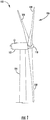
- FIG. 1 is a perspective view of a portion of an exemplary wind turbine 100.
- Wind turbine 100 includes a nacelle 102 housing a generator (not shown in FIG. 1 ).
- Nacelle 102 is mounted on a tower 104 (a portion of tower 104 being shown in FIG. 1 ).
- Tower 104 may have any suitable height that facilitates operation of wind turbine 100 as described herein.
- Wind turbine 100 also includes a rotor 106 that includes three blades 108 attached to a rotating hub 110.
- wind turbine 100 includes any number of blades 108 that facilitate operation of wind turbine 100 as described herein.
- Blades 108 may be pitched along an axis of each blade 108.
- each blade 108 may be pitched to feather the blade 108 into or out of the wind.
- blades 108 can be pitched by a blade pitch system (not shown in FIG. 1 ) operatively coupled to blades 108.
- FIG. 2 is a schematic view of an exemplary wind turbine system 200 that may be used with wind turbine 100.
- Wind turbine system 200 can include a wind turbine 100, which can include one or more blades 108.
- Wind turbine 100 can be coupled to an electric grid 210.
- Power generated by wind turbine 100 can be provided to a turbine bus 212.
- the power generated by wind turbine 100 can be a multi-phase (e.g., three-phase) power.
- a switch/breaker 214 can be used to selectively couple wind turbine 100 to electric grid 210 by coupling turbine bus 212 to grid bus 216.
- Wind turbine system 200 can further include a blade pitch system 220.
- Blade pitch system 220 can include a power source 222 and one or more motors 224.
- the one or more motors 224 can pitch one or more blades 108 of the wind turbine 100.
- a single motor 224 can pitch a plurality of blades 108, such as all blades 108.
- each blade 108 can be pitched by a respective motor 224.
- the one or more motors 224 can be used to pitch the blades 108 during a power loss event, such as a grid fault.
- the one or more motors 224 can be used to feather the blades 108 out of the wind.
- a power loss event for a primary power source for a blade pitch system 220 may occur, such as when a fault between an electrical grid 210 and a blade pitch system 220 occurs.
- the one or more motors can be powered during the power loss event by the power source 222.
- Power source 222 can be used to provide power to the one or more motors 224.
- power source 222 can include a plurality of energy storage devices, as described herein. Energy stored in the energy storage devices can be provided to the one or more motors 224 in order to pitch the blades 108.
- energy stored in the energy storage devices can be provided to the one or more motors 224 when a primary source of power is not available, such as during a power loss event.
- blade pitch system 220 can be coupled to electric grid 210.
- power from electric grid can be provided to the blade pitch system 220 and stored in the power source 222.
- the blade pitch system 220 can be selectively coupled to the electric grid 210 by a switch 230.
- Wind turbine system 200 can further include a control device 240.
- Control device 240 can be configured to control the blade pitch system 220 to pitch the blades 108.
- control device 240 can electrically couple power source 222 to the one or more motors 224 to provide power to the one or more motors 224.
- control device 240 can be configured to determine that a power loss event has occurred.
- the control device 240 can be configured to receive one or more signals indicative of a grid disturbance, such as from one or more voltage sensors or current sensors coupled to electric grid 210.
- the control device 240 can be configured to determine that a power loss event in a primary source of power for a blade pitch system 220 has occurred.
- the control device can determine that a power loss event has occurred by detecting a voltage or current anomaly of the electric grid 210.
- control device 240 can be configured to determine that an energy storage device in a power source 222 has failed. For example, control device 240 can be configured to detect a voltage across a bypass current device in a power source 222. In some implementations, the control device 240 can be configured to determine that an energy storage device in a power source 222 has failed based at least in part on a voltage across a bypass current device in the power source 222, as described herein.
- a control device 240 can further provide an alert for scheduled maintenance to be performed on a failed energy storage device.
- control device 240 can be configured to provide an output to a computing system, a display, or other output which can alert a technician that an energy storage device has failed.
- the specific failed energy storage device can be identified. A technician can then replace the failed energy storage device.
- control device 240 can be configured to control a switching device in a power source 222.
- power source 222 can include one or more IGBT or MOSFET switching devices as bypass current devices.
- control device 240 can be configured to control the MOSFET or IGBT switching devices to allow the bypass current to bypass a failed energy storage device.
- Wind turbine system 200 can further include additional elements, such as transformers, power converters, switches, breakers, system protection devices, or other elements to provide the functionality described herein.
- transformers can transform power from a first voltage to a second voltage
- power converters can convert power from AC power to DC power, as needed.
- blade pitch system 220 can include a plurality of energy storage devices 310 coupled in series.
- the energy storage devices 310 can be, for example, batteries or supercapacitors.
- the energy storage devices can further be configured to provide power to one or more motors 224 in order to pitch one or more blades 108.
- the energy storage devices 310 can be coupled to the motor 224 by a control device 240 (not shown).
- a control device 240 can close one or more switches (not shown) in order to couple the energy storage devices 310 to the motor 224.
- the blade pitch system 220 can further include one or more bypass current devices 320.
- the bypass current devices can be configured to allow a bypass current to bypass one or more failed energy storage devices 310.
- the failed energy storage device can create an open circuit, which can prevent a current from flowing from the energy storage devices 310 to the one or more motors 224.
- the bypass current device(s) 320 can allow it bypass current to bypass the one or more failed energy storage devices 310 in the plurality of energy storage devices 310.
- the bypass current device(s) can be power diodes 330.
- a power diode 330 can be coupled in parallel with at least one energy storage device 310.
- each energy storage device 310 can have a power diode 330 coupled in parallel with the respective energy storage device 310.
- a power diode can be coupled in parallel with a plurality of energy storage devices 310.
- a reversed voltage can be a negative voltage, or a voltage below a threshold voltage.
- a corresponding power diode 330 coupled in parallel can conduct.
- a failed energy storage device 312 can create an open circuit in the series-connected energy storage devices 310.
- the failed energy storage device 312 can create a reversed voltage (e.g., a negative, zero, or voltage below a threshold) across a corresponding power diode 332, thereby allowing a bypass current 350 to bypass the failed energy storage device 312.
- the bypass current 350 can bypass the failed energy storage device 312, thereby allowing power from the energy storage devices 310 to be provided to the one or more motors 224.
- one or more fuses 340 can be coupled between the at least one energy storage device 310 in the plurality of energy storage devices 310 and a bypass current device 320.
- a plurality of fuses 340 can be included in a blade pitch system 220, wherein each fuse 340 is coupled between at least one energy storage device 310 and at least one bypass current device 320 coupled in parallel with the at least one energy storage device 310.
- each energy storage device 310 can include a first node (e.g., a - node) and a second node (e.g., a + node).
- a fuse 340 can be coupled to the second node of each energy storage device 210 and a bypass current device 320.
- each fuse 340 can be configured to protect against a short circuit in a bypass current device 320 or an incorrectly installed bypass current device 320. as described herein.
- the blade pitch system 220 can further include system protection elements, such as a fuse 370 and an inductor loop comprising an inductor 360 and two inductor diodes 362 coupled to the one or more motors 224.
- system protection elements such as a fuse 370 and an inductor loop comprising an inductor 360 and two inductor diodes 362 coupled to the one or more motors 224.
- a shunt resistor 364 can be coupled to an energy storage device 310 in the plurality of energy storage devices, as shown in FIG. 3 .
- a ground 366 can also be included in the blade pitch system 220.
- a blade pitch system 220 can further include a control device, such as a control device 240.
- the bypass current device 320 can be a switching device 380, such as an IGBT or MOSFET switching device 380.
- control device 240 can be configured to determine that an energy storage device 310 has failed.
- a control device 240 can be configured to detect a voltage across a bypass current device 320, such as a switching device 380.
- the control device 240 can be configured to determine that an energy storage device 310 has failed based at least in part on a voltage across the bypass current device 320.
- control device 240 can be configured to control a switching device 380 to allow a bypass current 350 to bypass a failed energy storage device 312.
- the control device 240 can detect that an energy storage device 310 is a failed energy storage device 312 based at least in part on a voltage across a bypass current device 320 (e.g., switching device 382).
- the control device 240 can further control the corresponding bypass current device 320 (e.g., switching device 382) to allow the bypass current device 250 to flow to allow the bypass current 350 to bypass the failed energy storage device 312.
- the control device 240 can send a control signal to close the switching device 382 to allow the bypass current 350 to flow.
- the control device 240 can be configured to determine that an energy storage device 310 has failed, and further control a switching device 310 to allow a bypass current 350 to bypass the failed energy storage device 312.
- FIG. 5 an example benefit provided by the inclusion of one or more fuses 340 is depicted. Elements that are the same or similar to those as in FIGS. 3 and 4 are referred to with the same reference numerals.
- Power diode 334 has been incorrectly installed in the blade pitch system 220.
- power diode 334 is installed backwards. In such a situation, power diode 334 will allow a very high current to flow during normal operation of the corresponding energy storage device 314.
- Fuse 334 can be configured to protect against the incorrectly installed bypass current device by, for example, being sized such that fuse 344 will blow in the event of a high current flowing through incorrectly installed power diode 334.
- Fuse 346 can be configured to protect against a short circuit in the power diode 336 by, for example, being sized such that fuse 346 will blow in the event of a high current flowing through the short-circuited power diode 336.
- the fuses 340 can provide protection for the blade pitch system 220, and can allow for safer operation of the blade pitch system 220 such as, for example, when a technician perform service on the blade pitch system 220.
- a bypass current device 320 can be coupled in parallel with a plurality of energy storage devices 310.
- each bypass current device 320 e.g., power diode
- a fuse 340 can be coupled between at least one energy storage device 310 and a bypass current device 320, as shown.
- a bypass current device 320 can be coupled in parallel with a plurality of energy storage devices 310.
- each bypass current device 320 e.g., power diode
- a fuse 340 can be coupled between at least one energy storage device 310 and a bypass current device 320, as shown.
- a blade pitch system 220 according to additional aspects of the present disclosure is depicted. Elements that are the same or similar to those as in FIGS. 3-7 are referred to with the same reference numerals.
- a single bypass current device 320 can be coupled in parallel with a plurality of energy storage devices 310.
- one bypass current device 320 e.g., power diode
- a fuse 340 can be coupled between at least one energy storage device 310 and a bypass current device 320, as shown.
- a bypass current device 320 e.g., power diode
- a fuse 340 can be coupled between every other bypass current device 320 and at least one energy storage device 310, as shown, while the alternating bypass current devices can be directly coupled to a corresponding energy storage device 310.
- a blade pitch system 220 according to additional aspects of the present disclosure is depicted. Elements that are the same or similar to those as in FIGS. 3-9 are referred to with the same reference numerals.
- a bypass current device 320 e.g., power diode
- a fuse 340 can be coupled between every other bypass current device 320 and at least one energy storage device 310, as shown, while the alternating bypass current devices can be directly coupled to a corresponding energy storage device 310.
- FIG. 11 a blade pitch system 220 according to additional aspects of the present disclosure is depicted. Elements that are the same or similar to those as in FIGS. 3-10 are referred to with the same reference numerals.
- two bypass current devices 320 e.g., power diodes
- a single fuse 340 can be coupled between the two bypass current devices and two energy storage devices 310, as shown.
- FIG. 12 a blade pitch system 220 according to additional aspects of the present disclosure is depicted. Elements that are the same or similar to those as in FIGS. 3-11 are referred to with the same reference numerals.
- three bypass current devices 320 e.g., power diodes
- a plurality e.g., two
- Two fuses 340 can be included to provide protection, as shown.
- a blade pitch system 220 according to additional aspects of the present disclosure is depicted. Elements that are the same or similar to those as in FIGS. 3-12 are referred to with the same reference numerals.
- a bypass current device 320 e.g., power diode
- a single energy storage device 310 In the example blade pitch system 220 depicted in FIG. 13 , no fuses 340 are included.
- each bypass current device 320 can be coupled in parallel with a plurality of energy storage devices 310.
- FIG. 14 a flow diagram of an example method (1400) for providing power to one or more motors of a blade pitch system to pitch one or more blades of a wind turbine is depicted.
- a wind turbine 100 can include a plurality of blades 108.
- One or more motors 224 in a blade pitch system 220 can be configured to pitch the blades 108.
- Some or all of the steps in method 1400 can be implemented by a control device or control system, such as a control device 240 or control device/system 1510 depicted in FIGS. 2 , 4 , and 15 .
- FIG. 14 depicts steps performed in a particular order for purposes of illustration and discussion. Those of ordinary skill in the art, using the disclosures provided herein, will understand that various steps of any of the methods disclosed herein can be adapted, omitted, rearranged, or expanded in various ways without deviating from the scope of the present disclosure.
- a method (1400) can include determining that a power loss event has occurred.
- a control device 240 can be configured to receive one or more signals from one or more sensors connected to an electrical grid 210.
- the control device 240 can be configured to determine that a grid disturbance has occurred by detecting a voltage or current anomaly of the electrical grid.
- a grid disturbance can be a grid fault
- a control device 240 can determine that a grid disturbance has occurred when a voltage or current exceeds or drops below one or more thresholds.
- a power loss event e.g., a grid fault
- a control device 240 can be configured to determine that a primary source of power for a blade pitch system 220 has failed.
- a control device 240 can monitor a voltage and/or current from a primary power source.
- the method (1400) can include controlling a power source to provide power to one or more motors of the blade pitch system.
- a control device 240 can couple a power source 222 to one or more motors 224 by, for example, closing one or more switches in order to allow energy stored in the power source 222 to be provided to the one or more motors 224 in order to pitch one or more blades 108 of a wind turbine 100.
- the method (1400) can include determining that an energy storage device has failed.
- a control device 240 can be configured to obtain one or more signals indicative of a voltage across a bypass current device 320 in a blade pitch system 220.
- the control device 240 can be configured to determine that an energy storage device 310 has failed based at least in part on the voltage across the bypass current device 320. For example, a voltage across a bypass current device 220 can drop below a threshold, or become negative. In such a case, the control device 240 can be configured to determine that an energy storage device 310 has failed.
- the control device 240 can further control a power source to provide power to one or more motors of the blade pitch system by, for example, at (1410), controlling the switching device to allow a bypass current to bypass the failed energy storage device 310.
- a bypass current device 320 can be a MOSFET or IGBT switching device 380.
- a control device 240 can be configured to provide one or more switching commands to the MOSFET or IGBT switching device 380 to allow a bypass current to flow through the MOSFET or IGBT switching device 380 to bypass the failed energy storage device 310.
- the method (1400) can include providing an alert for scheduled maintenance to be performed on a failed energy storage device.
- the control device 240 can be configured to provide an output to a computing system, a display, or other output which can alert a technician that an energy storage device 310 has failed.
- the specific failed energy storage device 310 can be identified. A technician can then replace the failed energy storage device 310.
- the method (1400) can allow for providing power to one or more motors of a blade pitch system to pitch one or more blades of a wind turbine during a power loss event. Further, the method (1400) can allow for a bypass current device to be used to allow a bypass current to bypass one or more failed energy storage devices.
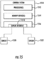
- control device/system 1510 can be used, for example, as control device 240 shown in FIGS. 2 and 4 and/or to implement any of the regulators or modules described herein.
- the control device/system 1510 can include one or more processor(s) 1512 and one or more memory device(s) 1514.
- the processor(s) 1512 and memory device(s) 1514 can be distributed so that they are located at one more locales or with different devices.
- the processor(s) 1512 and memory device(s) 1514 can be configured to perform a variety of computer-implemented functions and/or instructions (e.g., performing the methods, steps, calculations and the like and storing relevant data as disclosed herein).
- the instructions when executed by the processor(s) 1512 can cause the processor(s) 1512 to perform operations according to example aspects of the present disclosure.
- the instructions when executed by the processor(s) 1512 can cause the processor(s) 1512 to implement the method of FIG. 14 (1400) discussed herein.
- control device 1510 can include a communication interface 1516 to facilitate communications between the control device 1510 and various components of a wind turbine system 200, blade pitch system 220, a wind farm, or electric grid 210, including power parameters, current parameters, voltage parameters, or other parameters described herein.
- the communication interface 1518 can include a sensor interface 1518 (e.g., one or more analog-to-digital converters) to permit signals transmitted from one or more sensors 1520, 1522 to be converted into signals that can be understood and processed by the processor(s) 1512.
- the sensors e.g. sensors 1520, 1522
- the signals can be communicated using any suitable communications protocol.
- the sensors (1520, 1522) can be, for example, voltage sensors, current sensors, power sensors, or any other sensor device described herein.
- the processor(s) 1512 can be configured to receive one or more signals from the sensors 1520 and 1522. For instance, in some embodiments, the processor(s) 1512 can receive signals indicative of a current from the sensor 1520. In some embodiments, the processor(s) 1512 can receive signals indicative of voltage (e.g. grid voltage, voltage across a bypass current device) from sensor 1522.
- voltage e.g. grid voltage, voltage across a bypass current device
- the term "processor” refers not only to integrated circuits referred to in the art as being included in a computer, but also refers to a control device, a microcontrol device, a microcomputer, a programmable logic control device (PLC), an application specific integrated circuit, and other programmable circuits.
- the memory device(s) 1514 can generally include memory element(s) including, but not limited to, computer readable medium (e.g., random access memory (RAM)), computer readable non-volatile medium (e.g., a flash memory), a compact disc-read only memory (CD-ROM), a magneto-optical disk (MOD), a digital versatile disc (DVD) and/or other suitable memory elements.
- RAM random access memory
- CD-ROM compact disc-read only memory
- MOD magneto-optical disk
- DVD digital versatile disc
- Such memory device(s) 1514 can generally be configured to store suitable computer-readable instructions that, when implemented by the processor(s) 1512, configure the control device 1510 to perform
Description
- The present disclosure relates generally to wind turbines, and more particularly to methods and systems for a providing power to one or more motors in a blade pitch system for a wind turbine during a power loss event.
- The document
US 2013/193752 A1 discloses a rotor blade adjustment system for a wind turbine. - Generally, a wind turbine includes a rotor that includes a rotatable hub assembly having multiple blades. The blades transform wind energy into a mechanical rotational torque that drives one or more generators via the rotor. The generators are sometimes, but not always, rotationally coupled to the rotor through a gearbox. The gearbox steps up the inherently low rotational speed of the rotor for the generator to efficiently convert the rotational mechanical energy to electrical energy, which is fed into an electrical grid via at least one electrical connection. Gearless direct drive wind turbines also exist. The rotor, generator, gearbox and other components are typically mounted within a housing, or nacelle, that is positioned on top of a tower.
- During operation of the wind turbine, however, grid disturbances may occur. For example, a voltage or current anomaly, such as a voltage drop, may occur when parts of an electrical grid experience a grid fault. In such an instance, the wind turbine may need to be electrically isolated from the grid. For example, one or more breakers or switches may need to be opened to electrically isolate the wind turbine from the electrical grid. The wind turbine may further need to be shut down so that the wind turbine does not continue to produce power.
- When a wind turbine is shut down, the blades of the wind turbine may need to be pitched in order to feather the blades so that the wind does not mechanically rotate the blades. For example, one or more motors of a blade pitch system can mechanically pitch one or more blades on the wind turbine in order to feather the blades out of the wind. However, in a typical configuration, when a wind turbine is disconnected from the electrical grid, the blade pitch system may be unpowered, and therefore unable to pitch the blades. In some wind turbine systems, a backup power source may be configured to provide power to the one or more motors in the blade pitch system.
- However, when an energy storage device, such as a battery cell, fails in such a backup power source, the blade pitch system may fail and be unable to pitch the blades of the wind turbine.
- Various aspects and advantages of the invention will be set forth in part in the following description, or may be clear from the description, or may be learned through practice of the invention.
- One example aspect of the present disclosure is directed to a blade pitch system for a wind turbine as defined in claim 1.
- Another example aspect of the present disclosure is directed a method for providing power to one or more motors of a blade pitch system as defined in claim 11.
- Yet another example aspect of the present disclosure is directed to a wind turbine system. The wind turbine system can include a wind turbine comprising one or more blades. The wind turbine system can further include a blade pitch system. The blade pitch system can include one or more motors configured to pitch the one or more blades. The blade pitch system can further include a power source. The power source can include a plurality of energy storage devices coupled in series. The plurality of energy storage devices can be configured to provide power to the one or more motors during a power loss event. The power source can further include at least one bypass current device configured to allow a bypass current to provide power from at least one energy storage device to the one or more motors. The bypass current can be a current that bypasses one or more failed energy storage devices in the plurality of energy storage devices. The at least one bypass current device can be a diode, a MOSFET switching device, or an IGBT switching device.
- Variations and modifications can be made to these example embodiments of the present disclosure.
- Various features, aspects and advantages of the present invention will become better understood with reference to the following description and appended claims. The accompanying drawings, which are incorporated in and constitute a part of this specification, illustrate embodiments of the invention and, together with the description, serve to explain the principles of the invention.
- In the drawings:
-
FIG. 1 depicts a perspective view of a portion of a wind turbine according to example aspects of the present disclosure; -
FIG. 2 depicts a schematic view of wind turbine system including a blade pitch system according to example aspects of the present disclosure; -
FIG. 3 depicts a blade pitch system according to example aspects of the present disclosure; -
FIG. 4 depicts a problem addressed by a blade pitch system according to example aspects of the present disclosure; -
FIG. 5 depicts a blade pitch system according to example aspects of the present disclosure; -
FIG. 6 depicts a blade pitch system according to example aspects of the present disclosure; -
FIG. 7 depicts a blade pitch system according to example aspects of the present disclosure; -
FIG. 8 depicts a blade pitch system according to example aspects of the present disclosure; -
FIG. 9 depicts a blade pitch system according to example aspects of the present disclosure; -
FIG. 10 depicts a blade pitch system according to example aspects of the present disclosure; -
FIG. 11 depicts a blade pitch system according to example aspects of the present disclosure; -
FIG. 12 depicts a blade pitch system according to example aspects of the present disclosure; -
FIG. 13 depicts a blade pitch system according to example aspects of the present disclosure; -
FIG. 14 depicts a flow diagram of a method according to example aspects of the present disclosure; -
FIG. 15 depicts an example control device according to example aspects of the present disclosure. - Reference now will be made in detail to embodiments of the invention, one or more examples of which are illustrated in the drawings. Each example is provided by way of explanation of the invention, not limitation of the invention. In fact, it will be apparent to those skilled in the art that various modifications and variations can be made in the present invention without departing from the scope of the invention which is defined by the appended claims.
- Generally, example aspects of the present disclosure are directed to blade pitch systems and control methods for a blade pitch system in a wind turbine system. More particularly, a wind turbine system can include a wind turbine with one or more blades, and a blade pitch system. The blade pitch system can include one or more motors configured to pitch the one or more blades of the wind turbine. For example, in some implementations, each blade of a wind turbine can have an individual motor configured to pitch the blade. In some implementations, a single motor can be configured to pitch a plurality of blades, such as by rotating a gearing mechanism that pitches each blade on the wind turbine.
- The blade pitch system can further include a power source (e.g., a backup power source). For example, a plurality of energy storage devices can be coupled in series. The energy storage devices can be, for example, batteries or supercapacitors. The energy storage devices can be configured to provide power to the one or more motors during a power loss event. For example, as used herein, the term "power loss event" can mean any instance in which a primary source of power is not provided to the blade pitch system. For example, during a grid fault, the wind turbine may be electrically isolated from an electrical grid, and therefore be unable to receive electrical power from the electrical grid.
- The energy storage devices coupled in series will provide a stacked voltage, which can be used to power the one or more motors. However, when an energy storage device fails, the failed energy storage device may create an open circuit, thus not allowing any current to flow to the one or more motors.
- According to example aspects of the present disclosure, the power source of the blade pitch system can further include at least one bypass current device configured to allow a bypass current device to provide power from at least one energy storage device to the one or more motors. For example, the bypass current device can be a diode, a power diode, a Zener diode, or a switching device, such as an IGBT or MOSFET switching device. The bypass current can be a current that bypasses one or more failed energy storage devices in the plurality of energy storage devices, thereby allowing the one or more motors to pitch the one or more blades of the wind turbine.
- In some implementations, the blade pitch system can include a plurality of bypass current devices, and each energy storage device can have a bypass current device coupled in parallel with the respective energy storage device. In some implementations, a bypass current device can be coupled in parallel with a plurality of energy storage devices.
- For example, one or more power diodes can be positioned in parallel with one or more energy storage devices. During normal operation, the one or more power diodes will prevent a current from flowing through them. However, when an energy storage device fails open or with a high resistance, a reversed voltage will be impressed on the failed energy storage device due to the other energy storage devices in the system. The reversed voltage will cause the power diode to conduct, thereby limiting the reversed voltage on the failed energy storage device. Further, as the power diode conducts, the bypass current can flow to other downstream energy storage devices, completing the electrical circuit. In this way, the bypass current can flow through the bypass current device to complete the circuit to provide power to the one or more motors in the blade pitch system.
- In some implementations, the bypass current device can be a switching device, such as a semiconductor switching device (e.g., MOSFET or IGBT switching device). For example, a control device can be configured to determine that an energy storage device has failed. In some implementations, the control device can be configured to determine that an energy storage device has failed based at least in part on a voltage across the bypass current device. For example, a voltage across the bypass current device (e.g., diode, IGBT or MOSFET) can be measured, and when the voltage becomes reversed or dips below a threshold voltage, the control device can be configured to determine that a corresponding energy storage device has failed. The control device can further be configured to control the switching device to allow the bypass current to bypass the failed energy storage device. In this way, the bypass current can flow through the bypass current device to complete the circuit to provide power to the one or more motors in the blade pitch system.
- In some implementations, the control device can further be configured to provide an alert for scheduled maintenance to be performed on the failed energy storage device. For example, after determining that an energy storage device has failed, the control device can be configured to provide an output to a computing system, a display, or other output which can alert a technician that an energy storage device has failed. In some implementations, the specific failed energy storage device can be identified. A technician can then replace the failed energy storage device.
- As noted, the bypass current device can be positioned in parallel with at least one energy storage device. In some implementations, a bypass current device can be positioned in parallel with a plurality of energy storage devices. For example, two or more energy storage devices can be coupled in series, and the bypass current device can be positioned in parallel with the two or more energy storage devices.
- According to the invention, the blade pitch system includes a fuse coupled between at least one energy storage device in the plurality of energy storage devices and the at least one bypass current device. The bypass current can flow through the fuse. For example, each energy storage device can include a plurality of nodes, a first node (e.g., a node at a first voltage) and a second node (e.g., a node at a second voltage) when two energy storage devices are coupled in series, a first node of a first energy storage device can be coupled to a second node of a second energy storage device. In some implementations, a fuse can be coupled at node where the two energy storage devices are coupled together. In some implementations, a fuse can be coupled to only a single node of an energy storage device, such as at the ends of a string of energy storage devices coupled in series.
- The fuse can further be coupled to a bypass current device. For example, a bypass current device can have a first node on one end of the bypass current device, and a second node on the other end of the bypass current device. In some implementations, a plurality of bypass current devices can be coupled in series, with each bypass current device in parallel with one or more energy storage devices. In some implementations, the fuse can be coupled to a node between two bypass current devices. In some implementations, a fuse can be coupled to only a single node of a bypass current device, such as at the end of a string of bypass current devices coupled in series.
- In some implementations, the fuse can be configured to protect against a short circuit in a bypass current device for an incorrectly installed bypass current device. For example, should a bypass current device (e.g., power diode) short, a short circuit can be created across the bypass current device, allowing for a very high current to flow through the bypass current device. A fuse can be configured to protect against a short by, for example, being sized such that the fuse burns up when the short circuit begins flowing. Similarly, a fuse can be configured to protect against an incorrectly installed bypass current device. For example, should a power diode be installed backwards, in a normal operating mode, the voltage across the power diode would cause a very high current to flow. The fuse can be configured to protect against the incorrectly installed bypass current device by, for example, being sized such as the fuse burns up when the high current begins flowing.
- In some implementations, a fuse can be configured to protect a plurality of energy storage devices. For example, a bypass current device can be installed in parallel with a plurality of energy storage devices. The fuse can be coupled between at least one of the energy storage devices and the bypass current device. In some implementations, the blade pitch system can include a plurality of fuses, and each fuse can be coupled between at least one energy storage device and at least one bypass current device coupled in parallel with the respective energy storage device(s).
- In this way, the systems and methods according to example aspects of the present disclosure can have a technical effect of allowing for a bypass current to flow through a bypass current device, thereby bypassing a failed energy storage device in a power source of a blade pitch system. This can allow the power source to provide power to one or more motors of the blade pitch system in order to allow operation of the blade pitch system in the event of a failed energy storage device during a power loss event.
- Further, the systems and methods according to example aspects of the present disclosure can allow for detecting a failed energy storage device, and further alerting a technician that maintenance needs to be performed on the failed energy storage device. This can increase the reliability of a blade pitch system, and help to ensure that the blade pitch system is available in the event of a power loss event.
- Additionally, the systems and methods according to example aspects of the present disclosure can protect against short circuits and incorrectly installed components, thereby improving safety for a technician who may work on the blade pitch system.
- With reference now to the FIGS., example embodiments of the present disclosure will now be discussed in detail.
FIG. 1 is a perspective view of a portion of anexemplary wind turbine 100.Wind turbine 100 includes anacelle 102 housing a generator (not shown inFIG. 1 ).Nacelle 102 is mounted on a tower 104 (a portion oftower 104 being shown inFIG. 1 ).Tower 104 may have any suitable height that facilitates operation ofwind turbine 100 as described herein.Wind turbine 100 also includes arotor 106 that includes threeblades 108 attached to arotating hub 110. Alternatively,wind turbine 100 includes any number ofblades 108 that facilitate operation ofwind turbine 100 as described herein.Blades 108 may be pitched along an axis of eachblade 108. For example, eachblade 108 may be pitched to feather theblade 108 into or out of the wind. In some implementations,blades 108 can be pitched by a blade pitch system (not shown inFIG. 1 ) operatively coupled toblades 108. -
FIG. 2 is a schematic view of an exemplarywind turbine system 200 that may be used withwind turbine 100.Wind turbine system 200 can include awind turbine 100, which can include one ormore blades 108.Wind turbine 100 can be coupled to anelectric grid 210. Power generated bywind turbine 100 can be provided to aturbine bus 212. In some implementations, the power generated bywind turbine 100 can be a multi-phase (e.g., three-phase) power. In some implementations, a switch/breaker 214 can be used to selectively couplewind turbine 100 toelectric grid 210 by couplingturbine bus 212 togrid bus 216. -
Wind turbine system 200 can further include ablade pitch system 220.Blade pitch system 220 can include apower source 222 and one ormore motors 224. The one ormore motors 224 can pitch one ormore blades 108 of thewind turbine 100. In some implementations, asingle motor 224 can pitch a plurality ofblades 108, such as allblades 108. In some implementations, eachblade 108 can be pitched by arespective motor 224. The one ormore motors 224 can be used to pitch theblades 108 during a power loss event, such as a grid fault. For example, when a grid fault occurs requiring thewind turbine 100 to be electrically isolated from theelectric grid 210, the one ormore motors 224 can be used to feather theblades 108 out of the wind. Similarly, a power loss event for a primary power source for ablade pitch system 220 may occur, such as when a fault between anelectrical grid 210 and ablade pitch system 220 occurs. The one or more motors can be powered during the power loss event by thepower source 222. -
Power source 222 can be used to provide power to the one ormore motors 224. For example,power source 222 can include a plurality of energy storage devices, as described herein. Energy stored in the energy storage devices can be provided to the one ormore motors 224 in order to pitch theblades 108. For example, as described in greater detail with respect toFIGS. 3-13 , energy stored in the energy storage devices can be provided to the one ormore motors 224 when a primary source of power is not available, such as during a power loss event. - In some implementations,
blade pitch system 220 can be coupled toelectric grid 210. For example, power from electric grid can be provided to theblade pitch system 220 and stored in thepower source 222. In some implementations, theblade pitch system 220 can be selectively coupled to theelectric grid 210 by aswitch 230. -
Wind turbine system 200 can further include acontrol device 240.Control device 240 can be configured to control theblade pitch system 220 to pitch theblades 108. For example, in some implementations,control device 240 can electrically couplepower source 222 to the one ormore motors 224 to provide power to the one ormore motors 224. In some implementations,control device 240 can be configured to determine that a power loss event has occurred. For example, thecontrol device 240 can be configured to receive one or more signals indicative of a grid disturbance, such as from one or more voltage sensors or current sensors coupled toelectric grid 210. Similarly, thecontrol device 240 can be configured to determine that a power loss event in a primary source of power for ablade pitch system 220 has occurred. In some implementations, the control device can determine that a power loss event has occurred by detecting a voltage or current anomaly of theelectric grid 210. - In some implementations,
control device 240 can be configured to determine that an energy storage device in apower source 222 has failed. For example,control device 240 can be configured to detect a voltage across a bypass current device in apower source 222. In some implementations, thecontrol device 240 can be configured to determine that an energy storage device in apower source 222 has failed based at least in part on a voltage across a bypass current device in thepower source 222, as described herein. - In some implementations, a
control device 240 can further provide an alert for scheduled maintenance to be performed on a failed energy storage device. For example,control device 240 can be configured to provide an output to a computing system, a display, or other output which can alert a technician that an energy storage device has failed. In some implementations, the specific failed energy storage device can be identified. A technician can then replace the failed energy storage device. - In some implementations,
control device 240 can be configured to control a switching device in apower source 222. For example,power source 222 can include one or more IGBT or MOSFET switching devices as bypass current devices. In some implementations,control device 240 can be configured to control the MOSFET or IGBT switching devices to allow the bypass current to bypass a failed energy storage device. -
Wind turbine system 200 can further include additional elements, such as transformers, power converters, switches, breakers, system protection devices, or other elements to provide the functionality described herein. For example, transformers can transform power from a first voltage to a second voltage, and power converters can convert power from AC power to DC power, as needed. - Referring now to
FIG. 3 , an exampleblade pitch system 220 according to example aspects of the present disclosure is depicted. As shown,blade pitch system 220 can include a plurality ofenergy storage devices 310 coupled in series. Theenergy storage devices 310 can be, for example, batteries or supercapacitors. The energy storage devices can further be configured to provide power to one ormore motors 224 in order to pitch one ormore blades 108. - In some implementations, the
energy storage devices 310 can be coupled to themotor 224 by a control device 240 (not shown). For example, acontrol device 240 can close one or more switches (not shown) in order to couple theenergy storage devices 310 to themotor 224. - The
blade pitch system 220 can further include one or more bypasscurrent devices 320. The bypass current devices can be configured to allow a bypass current to bypass one or more failedenergy storage devices 310. For example, when anenergy storage device 310 in the plurality ofenergy storage devices 310 coupled in series fails, the failed energy storage device can create an open circuit, which can prevent a current from flowing from theenergy storage devices 310 to the one ormore motors 224. The bypass current device(s) 320 can allow it bypass current to bypass the one or more failedenergy storage devices 310 in the plurality ofenergy storage devices 310. - For example, as shown in
FIG. 3 , the bypass current device(s) can bepower diodes 330. In some implementations, apower diode 330 can be coupled in parallel with at least oneenergy storage device 310. In some implementations, eachenergy storage device 310 can have apower diode 330 coupled in parallel with the respectiveenergy storage device 310. In some implementations, a power diode can be coupled in parallel with a plurality ofenergy storage devices 310. When anenergy storage device 310 fails, an open circuit or high resistance can be created. In such a case, a reversed voltage or voltage below a threshold may be impressed on the failedenergy storage device 210 due to the otherenergy storage devices 310 in theblade pitch system 220. For example, a reversed voltage can be a negative voltage, or a voltage below a threshold voltage. When the reversed voltage occurs, acorresponding power diode 330 coupled in parallel can conduct. For example, as shown inFIG. 3 , a failedenergy storage device 312 can create an open circuit in the series-connectedenergy storage devices 310. The failedenergy storage device 312 can create a reversed voltage (e.g., a negative, zero, or voltage below a threshold) across a corresponding power diode 332, thereby allowing a bypass current 350 to bypass the failedenergy storage device 312. In this way, the bypass current 350 can bypass the failedenergy storage device 312, thereby allowing power from theenergy storage devices 310 to be provided to the one ormore motors 224. - In some implementations, one or
more fuses 340 can be coupled between the at least oneenergy storage device 310 in the plurality ofenergy storage devices 310 and a bypasscurrent device 320. In some implementations, a plurality offuses 340 can be included in ablade pitch system 220, wherein eachfuse 340 is coupled between at least oneenergy storage device 310 and at least one bypasscurrent device 320 coupled in parallel with the at least oneenergy storage device 310. For example, as shown inFIG. 3 , eachenergy storage device 310 can include a first node (e.g., a - node) and a second node (e.g., a + node). Afuse 340 can be coupled to the second node of eachenergy storage device 210 and a bypasscurrent device 320. In some implementations, eachfuse 340 can be configured to protect against a short circuit in a bypasscurrent device 320 or an incorrectly installed bypasscurrent device 320. as described herein. - The
blade pitch system 220 can further include system protection elements, such as afuse 370 and an inductor loop comprising aninductor 360 and twoinductor diodes 362 coupled to the one ormore motors 224. In some implementations, ashunt resistor 364 can be coupled to anenergy storage device 310 in the plurality of energy storage devices, as shown inFIG. 3 . In some implementations, aground 366 can also be included in theblade pitch system 220. - Referring now to
FIG. 4 , ablade pitch system 220 according to additional aspects of the present disclosure is depicted. Elements that are the same or similar to those as inFIG. 3 are referred to with the same reference numerals. As shown, ablade pitch system 220 can further include a control device, such as acontrol device 240. Additionally, the bypasscurrent device 320 can be aswitching device 380, such as an IGBT orMOSFET switching device 380. - In some implementations, the
control device 240 can be configured to determine that anenergy storage device 310 has failed. For example, acontrol device 240 can be configured to detect a voltage across a bypasscurrent device 320, such as aswitching device 380. Thecontrol device 240 can be configured to determine that anenergy storage device 310 has failed based at least in part on a voltage across the bypasscurrent device 320. - Further, the
control device 240 can be configured to control aswitching device 380 to allow a bypass current 350 to bypass a failedenergy storage device 312. For example, thecontrol device 240 can detect that anenergy storage device 310 is a failedenergy storage device 312 based at least in part on a voltage across a bypass current device 320 (e.g., switching device 382). Thecontrol device 240 can further control the corresponding bypass current device 320 (e.g., switching device 382) to allow the bypass current device 250 to flow to allow the bypass current 350 to bypass the failedenergy storage device 312. For example, thecontrol device 240 can send a control signal to close the switching device 382 to allow the bypass current 350 to flow. In this way, thecontrol device 240 can be configured to determine that anenergy storage device 310 has failed, and further control aswitching device 310 to allow a bypass current 350 to bypass the failedenergy storage device 312. - Referring now to
FIG. 5 , an example benefit provided by the inclusion of one ormore fuses 340 is depicted. Elements that are the same or similar to those as inFIGS. 3 and 4 are referred to with the same reference numerals. As shown,Power diode 334 has been incorrectly installed in theblade pitch system 220. For example,power diode 334 is installed backwards. In such a situation,power diode 334 will allow a very high current to flow during normal operation of the correspondingenergy storage device 314. Fuse 334 can be configured to protect against the incorrectly installed bypass current device by, for example, being sized such thatfuse 344 will blow in the event of a high current flowing through incorrectly installedpower diode 334. - Similarly,
power diode 336 has short-circuited. In such a situation, a high current can flow throughfuse 346. Fuse 346 can be configured to protect against a short circuit in thepower diode 336 by, for example, being sized such thatfuse 346 will blow in the event of a high current flowing through the short-circuitedpower diode 336. - In this way, the
fuses 340 can provide protection for theblade pitch system 220, and can allow for safer operation of theblade pitch system 220 such as, for example, when a technician perform service on theblade pitch system 220. - Referring now to
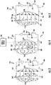
FIG. 6 , ablade pitch system 220 according to additional aspects of the present disclosure is depicted. Elements that are the same or similar to those as inFIGS. 3-5 are referred to with the same reference numerals. As shown, a bypasscurrent device 320 can be coupled in parallel with a plurality ofenergy storage devices 310. For example, as shown, each bypass current device 320 (e.g., power diode) is coupled in parallel with twoenergy storage devices 310. Afuse 340 can be coupled between at least oneenergy storage device 310 and a bypasscurrent device 320, as shown. - Referring now to
FIG. 7 , ablade pitch system 220 according to additional aspects of the present disclosure is depicted. Elements that are the same or similar to those as inFIGS. 3-6 are referred to with the same reference numerals. As shown, a bypasscurrent device 320 can be coupled in parallel with a plurality ofenergy storage devices 310. For example, as shown, each bypass current device 320 (e.g., power diode) is coupled in parallel with threeenergy storage devices 310. Afuse 340 can be coupled between at least oneenergy storage device 310 and a bypasscurrent device 320, as shown. - Referring now to
FIG. 8 , ablade pitch system 220 according to additional aspects of the present disclosure is depicted. Elements that are the same or similar to those as inFIGS. 3-7 are referred to with the same reference numerals. As shown, a single bypasscurrent device 320 can be coupled in parallel with a plurality ofenergy storage devices 310. For example, as shown, one bypass current device 320 (e.g., power diode) is coupled in parallel with twoenergy storage devices 310, while the remainingenergy storage devices 310 are each coupled in parallel with a corresponding bypasscurrent device 320. Afuse 340 can be coupled between at least oneenergy storage device 310 and a bypasscurrent device 320, as shown. - Referring now to
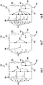
FIG. 9 , ablade pitch system 220 according to additional aspects of the present disclosure is depicted. Elements that are the same or similar to those as inFIGS. 3-8 are referred to with the same reference numerals. As shown, a bypass current device 320 (e.g., power diode) can be coupled in parallel with eachenergy storage device 310. Afuse 340 can be coupled between every other bypasscurrent device 320 and at least oneenergy storage device 310, as shown, while the alternating bypass current devices can be directly coupled to a correspondingenergy storage device 310. - Referring now to
FIG. 10 , ablade pitch system 220 according to additional aspects of the present disclosure is depicted. Elements that are the same or similar to those as inFIGS. 3-9 are referred to with the same reference numerals. As shown, a bypass current device 320 (e.g., power diode) can be coupled in parallel with eachenergy storage device 310. Afuse 340 can be coupled between every other bypasscurrent device 320 and at least oneenergy storage device 310, as shown, while the alternating bypass current devices can be directly coupled to a correspondingenergy storage device 310. - Referring now to
FIG. 11 , ablade pitch system 220 according to additional aspects of the present disclosure is depicted. Elements that are the same or similar to those as inFIGS. 3-10 are referred to with the same reference numerals. As shown, two bypass current devices 320 (e.g., power diodes) can each be coupled in parallel with a plurality (e.g., three) ofenergy storage devices 310. Asingle fuse 340 can be coupled between the two bypass current devices and twoenergy storage devices 310, as shown. - Referring now to
FIG. 12 , ablade pitch system 220 according to additional aspects of the present disclosure is depicted. Elements that are the same or similar to those as inFIGS. 3-11 are referred to with the same reference numerals. As shown, three bypass current devices 320 (e.g., power diodes) can each be coupled in parallel with a plurality (e.g., two) ofenergy storage devices 310. Two fuses 340 can be included to provide protection, as shown. - Referring now to
FIG. 13 , ablade pitch system 220 according to additional aspects of the present disclosure is depicted. Elements that are the same or similar to those as inFIGS. 3-12 are referred to with the same reference numerals. As shown, a bypass current device 320 (e.g., power diode) can be coupled in parallel with a singleenergy storage device 310. In the exampleblade pitch system 220 depicted inFIG. 13 , nofuses 340 are included. In some implementations (not shown), each bypasscurrent device 320 can be coupled in parallel with a plurality ofenergy storage devices 310. - Referring now to
FIG. 14 , a flow diagram of an example method (1400) for providing power to one or more motors of a blade pitch system to pitch one or more blades of a wind turbine is depicted. Awind turbine 100 can include a plurality ofblades 108. One ormore motors 224 in ablade pitch system 220 can be configured to pitch theblades 108. Some or all of the steps inmethod 1400 can be implemented by a control device or control system, such as acontrol device 240 or control device/system 1510 depicted inFIGS. 2 ,4 , and15 . In addition,FIG. 14 depicts steps performed in a particular order for purposes of illustration and discussion. Those of ordinary skill in the art, using the disclosures provided herein, will understand that various steps of any of the methods disclosed herein can be adapted, omitted, rearranged, or expanded in various ways without deviating from the scope of the present disclosure. - At (1402), a method (1400) can include determining that a power loss event has occurred. For example, a
control device 240 can be configured to receive one or more signals from one or more sensors connected to anelectrical grid 210. Thecontrol device 240 can be configured to determine that a grid disturbance has occurred by detecting a voltage or current anomaly of the electrical grid. For example, a grid disturbance can be a grid fault, and acontrol device 240 can determine that a grid disturbance has occurred when a voltage or current exceeds or drops below one or more thresholds. For example, when a voltage goes to zero, the control device can be configured to determine that a power loss event (e.g., a grid fault) has occurred. Similarly, acontrol device 240 can be configured to determine that a primary source of power for ablade pitch system 220 has failed. For example, acontrol device 240 can monitor a voltage and/or current from a primary power source. - At (1404), the method (1400) can include controlling a power source to provide power to one or more motors of the blade pitch system. For example, at (1406), a
control device 240 can couple apower source 222 to one ormore motors 224 by, for example, closing one or more switches in order to allow energy stored in thepower source 222 to be provided to the one ormore motors 224 in order to pitch one ormore blades 108 of awind turbine 100. - At (1408), the method (1400) can include determining that an energy storage device has failed. For example, a
control device 240 can be configured to obtain one or more signals indicative of a voltage across a bypasscurrent device 320 in ablade pitch system 220. Thecontrol device 240 can be configured to determine that anenergy storage device 310 has failed based at least in part on the voltage across the bypasscurrent device 320. For example, a voltage across a bypasscurrent device 220 can drop below a threshold, or become negative. In such a case, thecontrol device 240 can be configured to determine that anenergy storage device 310 has failed. - In some implementations in which a switching device is used as a bypass
current device 220, thecontrol device 240 can further control a power source to provide power to one or more motors of the blade pitch system by, for example, at (1410), controlling the switching device to allow a bypass current to bypass the failedenergy storage device 310. For example, a bypasscurrent device 320 can be a MOSFET orIGBT switching device 380. Acontrol device 240 can be configured to provide one or more switching commands to the MOSFET orIGBT switching device 380 to allow a bypass current to flow through the MOSFET orIGBT switching device 380 to bypass the failedenergy storage device 310. - At (1412), the method (1400) can include providing an alert for scheduled maintenance to be performed on a failed energy storage device. For example, the
control device 240 can be configured to provide an output to a computing system, a display, or other output which can alert a technician that anenergy storage device 310 has failed. In some implementations, the specific failedenergy storage device 310 can be identified. A technician can then replace the failedenergy storage device 310. - In this way, the method (1400) can allow for providing power to one or more motors of a blade pitch system to pitch one or more blades of a wind turbine during a power loss event. Further, the method (1400) can allow for a bypass current device to be used to allow a bypass current to bypass one or more failed energy storage devices.
- Referring now to
FIG. 15 , an example control device/system 1510 according to example embodiments of the present disclosure is depicted. The control device/system 1510 can be used, for example, ascontrol device 240 shown inFIGS. 2 and4 and/or to implement any of the regulators or modules described herein. In some embodiments, the control device/system 1510 can include one or more processor(s) 1512 and one or more memory device(s) 1514. The processor(s) 1512 and memory device(s) 1514 can be distributed so that they are located at one more locales or with different devices. - The processor(s) 1512 and memory device(s) 1514 can be configured to perform a variety of computer-implemented functions and/or instructions (e.g., performing the methods, steps, calculations and the like and storing relevant data as disclosed herein). The instructions when executed by the processor(s) 1512 can cause the processor(s) 1512 to perform operations according to example aspects of the present disclosure. For instance, the instructions when executed by the processor(s) 1512 can cause the processor(s) 1512 to implement the method of
FIG. 14 (1400) discussed herein. - Additionally, the
control device 1510 can include acommunication interface 1516 to facilitate communications between thecontrol device 1510 and various components of awind turbine system 200,blade pitch system 220, a wind farm, orelectric grid 210, including power parameters, current parameters, voltage parameters, or other parameters described herein. Further, thecommunication interface 1518 can include a sensor interface 1518 (e.g., one or more analog-to-digital converters) to permit signals transmitted from one ormore sensors e.g. sensors 1520, 1522) can be communicatively coupled to thecommunications interface 1518 using any suitable means, such as a wired or wireless connection. The signals can be communicated using any suitable communications protocol. The sensors (1520, 1522) can be, for example, voltage sensors, current sensors, power sensors, or any other sensor device described herein. - As such, the processor(s) 1512 can be configured to receive one or more signals from the
sensors sensor 1520. In some embodiments, the processor(s) 1512 can receive signals indicative of voltage (e.g. grid voltage, voltage across a bypass current device) fromsensor 1522. - As used herein, the term "processor" refers not only to integrated circuits referred to in the art as being included in a computer, but also refers to a control device, a microcontrol device, a microcomputer, a programmable logic control device (PLC), an application specific integrated circuit, and other programmable circuits. Additionally, the memory device(s) 1514 can generally include memory element(s) including, but not limited to, computer readable medium (e.g., random access memory (RAM)), computer readable non-volatile medium (e.g., a flash memory), a compact disc-read only memory (CD-ROM), a magneto-optical disk (MOD), a digital versatile disc (DVD) and/or other suitable memory elements. Such memory device(s) 1514 can generally be configured to store suitable computer-readable instructions that, when implemented by the processor(s) 1512, configure the
control device 1510 to perform the various functions as described herein. - The technology discussed herein makes reference to computer-based systems and actions taken by and information sent to and from computer-based systems. One of ordinary skill in the art will recognize that the inherent flexibility of computer-based systems allows for a great variety of possible configurations, combinations, and divisions of tasks and functionality between and among components. For instance, processes discussed herein can be implemented using a single computing device or multiple computing devices working in combination. Databases, memory, instructions, and applications can be implemented on a single system or distributed across multiple systems. Distributed components can operate sequentially or in parallel.
- Although specific features of various embodiments may be shown in some drawings and not in others, this is for convenience only.
- This written description uses examples to disclose the invention, including the preferred mode, and also to enable any person skilled in the art to practice the invention, including making and using any devices or systems and performing any incorporated methods. The patentable scope of the invention is defined by the claims, and may include other examples that occur to those skilled in the art.
Claims (13)
- A blade pitch system (220) for a wind turbine (100), the wind turbine (100) comprising one or more blades (108), the blade pitch system (220) comprising:one or more motors (224) configured to pitch the one or more blades (108) of the wind turbine (100); anda power source (222) comprising:a plurality of energy storage devices (310) coupled in series, the plurality of energy storage devices (310) configured to provide power to the one or more motors (224) during a power loss event; andat least one bypass current device (320) configured to allow a bypass current (350) to provide power from at least one of the plurality of energy storage devices (310) to the one or more motors (224);wherein the bypass current (350) comprises a current that bypasses one or more failed energy storage devices (312) in the plurality of energy storage devices (310); characterized bya fuse (340) coupled between at least one energy storage device (310) in the plurality of energy storage devices (310) and the at least one bypass current device (320);wherein the bypass current (350) flows through the fuse (340), andwherein the fuse (340) is configured to protect against a short circuit in the bypass current device (320) or an incorrectly installed bypass current device (320).
- The blade pitch system (220) of claim 1, wherein each energy storage device (310) comprises either a battery or a supercapacitor.
- The blade pitch system (220) of any preceding claim, wherein the bypass current device (320) comprises a power diode (330).
- The blade pitch system (220) of any preceding claim, further comprising:
a control device (240, 1510) configured to determine that an energy storage device (310) has failed. - The blade pitch system (220) of claim 4, wherein the control device (240, 1510) is configured to determine that an energy storage device (310) has failed based at least in part on a voltage across the at least one bypass current device (320).
- The blade pitch system (220) of claim 4 or 5, wherein the control device (240, 1510) is further configured to provide an alert for scheduled maintenance to be performed on the failed energy storage device (312).
- The blade pitch system (220) of one of the claims 4 to 6, wherein the bypass current device (320) comprises a switching device (380);
wherein the switching device (380) comprises a MOSFET or IGBT switching device (380); and
wherein the control device (240, 1510) is further configured to control the switching device (380) to allow the bypass current (350) to bypass the failed energy storage device (312). - The blade pitch system (220) of any preceding claim, wherein the at least one bypass current device (320) is positioned in parallel with at least one energy storage device (310).
- The blade pitch system (220) of any preceding claim, wherein the at least one bypass current device (320) comprises a plurality of bypass current devices (320); and wherein a bypass current device (320) is coupled in parallel with each energy storage device (310).
- The blade pitch system (220) of any preceding claim, further comprising: a plurality of fuses (340);
wherein each fuse (340) is coupled between at least one energy storage device (310) and at least one bypass current device (320) coupled in parallel with the at least one energy storage device (310). - A method for providing power to one or more motors (224) of a blade pitch system (220) according to any one of the preceding claims to pitch one or more blades (108) of a wind turbine (100), the method comprising:determining, by a control device (240, 1510), that a power loss event has occurred;causing, by the control device (240, 1510), a power source (222) to be electrically coupled to the one or more motors (224), the power source (222) comprising a plurality of energy storage devices (310) coupled in series and at least one bypass current device (320) coupled in parallel with at least one energy storage device (310);determining, by the control device (240, 1510), that an energy storage device (310) has failed; andcontrolling, by the control device (240, 1510), the bypass current device (320) to allow a bypass current (350) to bypass the failed energy storage device (312) to provide power to the one or more motors (224).
- The method of claim 11, wherein the bypass current device (320) comprises a MOSFET or IGBT switching device (380); and
wherein controlling, by the control device (240, 1510), the bypass current device (320) to allow a bypass current (350) to bypass the failed energy storage device (312) to provide power to the one or more motors (224) comprises controlling the MOSFET or IGBT switching device (380) to allow the bypass current (350) to bypass the failed energy storage device (312). - The method of claim 11 or claim 12, wherein determining, by a control device (240, 1510), that a power loss event has occurred comprises detecting, by the control device (240, 1510), a voltage or current anomaly of an electrical grid (210).
Applications Claiming Priority (1)
| Application Number | Priority Date | Filing Date | Title |
|---|---|---|---|
| US15/629,879 US11168663B2 (en) | 2017-06-22 | 2017-06-22 | Blade pitch system including power source for wind turbine |
Publications (2)
| Publication Number | Publication Date |
|---|---|
| EP3418559A1 EP3418559A1 (en) | 2018-12-26 |
| EP3418559B1 true EP3418559B1 (en) | 2020-12-02 |
Family
ID=62712855
Family Applications (1)
| Application Number | Title | Priority Date | Filing Date |
|---|---|---|---|
| EP18178485.1A Active EP3418559B1 (en) | 2017-06-22 | 2018-06-19 | Blade pitch system incluidng power source for wind turbine |
Country Status (5)
| Country | Link |
|---|---|
| US (1) | US11168663B2 (en) |
| EP (1) | EP3418559B1 (en) |
| CN (1) | CN109113928B (en) |
| DK (1) | DK3418559T3 (en) |
| ES (1) | ES2858401T3 (en) |
Families Citing this family (4)
| Publication number | Priority date | Publication date | Assignee | Title |
|---|---|---|---|---|
| US10965132B2 (en) * | 2018-09-14 | 2021-03-30 | General Electric Company | Grounding circuit for a backup power source |
| US11824345B2 (en) * | 2019-09-04 | 2023-11-21 | Texas Instruments Incorporated | Methods and apparatus to improve performance of power path protection devices |
| US11879425B2 (en) * | 2021-12-08 | 2024-01-23 | Ge Infrastructure Technology Llc | System and method for controlling blade pitch of wind turbine rotor blades in an idling state of the rotor hub |
| US11804336B2 (en) | 2022-03-11 | 2023-10-31 | General Electric Company | Ultracapacitor module with integrated bypass diode and related systems |
Family Cites Families (17)
| Publication number | Priority date | Publication date | Assignee | Title |
|---|---|---|---|---|
| DE10140793A1 (en) | 2001-08-20 | 2003-03-06 | Gen Electric | Device for adjusting the rotor blade of a rotor of a wind turbine |
| US7071579B2 (en) * | 2002-06-07 | 2006-07-04 | Global Energyconcepts,Llc | Wind farm electrical system |
| US6921985B2 (en) * | 2003-01-24 | 2005-07-26 | General Electric Company | Low voltage ride through for wind turbine generators |
| JP4233400B2 (en) | 2003-07-04 | 2009-03-04 | ナブテスコ株式会社 | Wind turbine blade pitch angle drive device |
| US7642748B2 (en) * | 2005-10-19 | 2010-01-05 | General Electric Company | Battery charging system and method of operating same |
| WO2007132303A1 (en) | 2006-05-13 | 2007-11-22 | Clipper Windpower Technology, Inc. | Wind turbine system with ac servo motor rotor blade pitch control, using super-capacitor energy storage |
| JP5319138B2 (en) | 2008-03-07 | 2013-10-16 | 株式会社東芝 | Battery system |
| US8128361B2 (en) * | 2008-12-19 | 2012-03-06 | Frontier Wind, Llc | Control modes for extendable rotor blades |
| US7942631B2 (en) * | 2009-10-26 | 2011-05-17 | General Electric Company | Method and apparatus for powering a pitch control system |
| DE102009044570A1 (en) | 2009-11-17 | 2011-05-19 | Ssb Wind Systems Gmbh & Co. Kg | Wind turbine |
| DE102010027857A1 (en) * | 2010-04-16 | 2011-10-20 | Sb Limotive Company Ltd. | Coupling unit and battery module with integrated pulse inverter and increased reliability |
| US8710800B2 (en) | 2011-07-26 | 2014-04-29 | GM Global Technology Operations LLC | Vehicle battery with cell balancing current paths and method of charging the same |
| WO2013060013A1 (en) * | 2011-10-28 | 2013-05-02 | General Electric Company | Blade pitch system for a wind turbine generator and method of operating the same |
| DE102012210010A1 (en) | 2012-06-14 | 2013-12-19 | Robert Bosch Gmbh | Energy storage device for producing power supply voltage for e.g. synchronous machine in hybrid car, has module intermediate circuit coupled with conversion circuit for selectively switching or bridging in supply strands |
| JP5585616B2 (en) * | 2012-06-26 | 2014-09-10 | 株式会社デンソー | Circuit protection device |
| US20150130421A1 (en) | 2013-11-08 | 2015-05-14 | John Joseph Bevilacqua, III | Battery management electronics with configurable battery module bypass control |
| CN104747373A (en) * | 2013-12-31 | 2015-07-01 | 通用电气公司 | System and method used for protecting standby variable-pitch control system of wind turbine battery |
-
2017
- 2017-06-22 US US15/629,879 patent/US11168663B2/en active Active
-
2018
- 2018-06-19 DK DK18178485.1T patent/DK3418559T3/en active
- 2018-06-19 EP EP18178485.1A patent/EP3418559B1/en active Active
- 2018-06-19 ES ES18178485T patent/ES2858401T3/en active Active
- 2018-06-22 CN CN201810650346.4A patent/CN109113928B/en active Active
Non-Patent Citations (1)
| Title |
|---|
| None * |
Also Published As
| Publication number | Publication date |
|---|---|
| CN109113928B (en) | 2022-07-08 |
| US11168663B2 (en) | 2021-11-09 |
| ES2858401T3 (en) | 2021-09-30 |
| BR102018012652A2 (en) | 2019-01-15 |
| CN109113928A (en) | 2019-01-01 |
| BR102018012652A8 (en) | 2022-12-27 |
| EP3418559A1 (en) | 2018-12-26 |
| US20180372072A1 (en) | 2018-12-27 |
| DK3418559T3 (en) | 2021-02-22 |
Similar Documents
| Publication | Publication Date | Title |
|---|---|---|
| EP3418559B1 (en) | Blade pitch system incluidng power source for wind turbine | |
| US8664788B1 (en) | Method and systems for operating a wind turbine using dynamic braking in response to a grid event | |
| US9667057B2 (en) | System and method for protecting a power converter during an adverse voltage event | |
| ES2401140T3 (en) | Wind power installation | |
| US10662923B2 (en) | Contingency autonomous yaw control for a wind turbine | |
| EP3284169B1 (en) | Wind turbine converter control | |
| EP3629440B1 (en) | System and method for controlling uninterruptible power supply of electrical power systems | |
| CN104747373A (en) | System and method used for protecting standby variable-pitch control system of wind turbine battery | |
| US10113533B2 (en) | System and method for reducing wind turbine oscillations caused by grid faults | |
| CA2901713C (en) | System and method for improving reactive current response time in a wind turbine | |
| EP3993208B1 (en) | System and method for operating a power generating asset | |
| US9945359B2 (en) | DC output wind turbine with power dissipation | |
| JP6445976B2 (en) | Converter system and wind power generation facility or hydroelectric generation facility | |
| US9797375B2 (en) | Blade pitch system with a dual winding actuator | |
| KR20160064873A (en) | Wind power generator pitch system and control method thereof | |
| BR102018012652B1 (en) | PADDLE STEP SYSTEM AND METHOD FOR SUPPLYING POWER |
Legal Events
| Date | Code | Title | Description |
|---|---|---|---|
| PUAI | Public reference made under article 153(3) epc to a published international application that has entered the european phase |
Free format text: ORIGINAL CODE: 0009012 |
|
| STAA | Information on the status of an ep patent application or granted ep patent |
Free format text: STATUS: THE APPLICATION HAS BEEN PUBLISHED |
|
| AK | Designated contracting states |
Kind code of ref document: A1 Designated state(s): AL AT BE BG CH CY CZ DE DK EE ES FI FR GB GR HR HU IE IS IT LI LT LU LV MC MK MT NL NO PL PT RO RS SE SI SK SM TR |
|
| AX | Request for extension of the european patent |
Extension state: BA ME |
|
| STAA | Information on the status of an ep patent application or granted ep patent |
Free format text: STATUS: REQUEST FOR EXAMINATION WAS MADE |
|
| 17P | Request for examination filed |
Effective date: 20190625 |
|
| RBV | Designated contracting states (corrected) |
Designated state(s): AL AT BE BG CH CY CZ DE DK EE ES FI FR GB GR HR HU IE IS IT LI LT LU LV MC MK MT NL NO PL PT RO RS SE SI SK SM TR |
|
| GRAP | Despatch of communication of intention to grant a patent |
Free format text: ORIGINAL CODE: EPIDOSNIGR1 |
|
| STAA | Information on the status of an ep patent application or granted ep patent |
Free format text: STATUS: GRANT OF PATENT IS INTENDED |
|
| INTG | Intention to grant announced |
Effective date: 20200626 |
|
| GRAS | Grant fee paid |
Free format text: ORIGINAL CODE: EPIDOSNIGR3 |
|
| GRAA | (expected) grant |
Free format text: ORIGINAL CODE: 0009210 |
|
| STAA | Information on the status of an ep patent application or granted ep patent |
Free format text: STATUS: THE PATENT HAS BEEN GRANTED |
|
| AK | Designated contracting states |
Kind code of ref document: B1 Designated state(s): AL AT BE BG CH CY CZ DE DK EE ES FI FR GB GR HR HU IE IS IT LI LT LU LV MC MK MT NL NO PL PT RO RS SE SI SK SM TR |
|
| REG | Reference to a national code |
Ref country code: GB Ref legal event code: FG4D |
|
| REG | Reference to a national code |
Ref country code: AT Ref legal event code: REF Ref document number: 1341200 Country of ref document: AT Kind code of ref document: T Effective date: 20201215 Ref country code: CH Ref legal event code: EP |
|
| REG | Reference to a national code |
Ref country code: IE Ref legal event code: FG4D |
|
| REG | Reference to a national code |
Ref country code: DE Ref legal event code: R096 Ref document number: 602018010278 Country of ref document: DE |
|
| REG | Reference to a national code |
Ref country code: DK Ref legal event code: T3 Effective date: 20210217 |
|
| PG25 | Lapsed in a contracting state [announced via postgrant information from national office to epo] |
Ref country code: GR Free format text: LAPSE BECAUSE OF FAILURE TO SUBMIT A TRANSLATION OF THE DESCRIPTION OR TO PAY THE FEE WITHIN THE PRESCRIBED TIME-LIMIT Effective date: 20210303 Ref country code: NO Free format text: LAPSE BECAUSE OF FAILURE TO SUBMIT A TRANSLATION OF THE DESCRIPTION OR TO PAY THE FEE WITHIN THE PRESCRIBED TIME-LIMIT Effective date: 20210302 Ref country code: RS Free format text: LAPSE BECAUSE OF FAILURE TO SUBMIT A TRANSLATION OF THE DESCRIPTION OR TO PAY THE FEE WITHIN THE PRESCRIBED TIME-LIMIT Effective date: 20201202 Ref country code: FI Free format text: LAPSE BECAUSE OF FAILURE TO SUBMIT A TRANSLATION OF THE DESCRIPTION OR TO PAY THE FEE WITHIN THE PRESCRIBED TIME-LIMIT Effective date: 20201202 |
|
| REG | Reference to a national code |
Ref country code: NL Ref legal event code: MP Effective date: 20201202 |
|
| REG | Reference to a national code |
Ref country code: AT Ref legal event code: MK05 Ref document number: 1341200 Country of ref document: AT Kind code of ref document: T Effective date: 20201202 |
|
| PG25 | Lapsed in a contracting state [announced via postgrant information from national office to epo] |
Ref country code: PL Free format text: LAPSE BECAUSE OF FAILURE TO SUBMIT A TRANSLATION OF THE DESCRIPTION OR TO PAY THE FEE WITHIN THE PRESCRIBED TIME-LIMIT Effective date: 20201202 Ref country code: LV Free format text: LAPSE BECAUSE OF FAILURE TO SUBMIT A TRANSLATION OF THE DESCRIPTION OR TO PAY THE FEE WITHIN THE PRESCRIBED TIME-LIMIT Effective date: 20201202 Ref country code: SE Free format text: LAPSE BECAUSE OF FAILURE TO SUBMIT A TRANSLATION OF THE DESCRIPTION OR TO PAY THE FEE WITHIN THE PRESCRIBED TIME-LIMIT Effective date: 20201202 Ref country code: BG Free format text: LAPSE BECAUSE OF FAILURE TO SUBMIT A TRANSLATION OF THE DESCRIPTION OR TO PAY THE FEE WITHIN THE PRESCRIBED TIME-LIMIT Effective date: 20210302 |
|
| PG25 | Lapsed in a contracting state [announced via postgrant information from national office to epo] |
Ref country code: NL Free format text: LAPSE BECAUSE OF FAILURE TO SUBMIT A TRANSLATION OF THE DESCRIPTION OR TO PAY THE FEE WITHIN THE PRESCRIBED TIME-LIMIT Effective date: 20201202 Ref country code: HR Free format text: LAPSE BECAUSE OF FAILURE TO SUBMIT A TRANSLATION OF THE DESCRIPTION OR TO PAY THE FEE WITHIN THE PRESCRIBED TIME-LIMIT Effective date: 20201202 |
|
| REG | Reference to a national code |
Ref country code: LT Ref legal event code: MG9D |
|
| PG25 | Lapsed in a contracting state [announced via postgrant information from national office to epo] |
Ref country code: SM Free format text: LAPSE BECAUSE OF FAILURE TO SUBMIT A TRANSLATION OF THE DESCRIPTION OR TO PAY THE FEE WITHIN THE PRESCRIBED TIME-LIMIT Effective date: 20201202 Ref country code: EE Free format text: LAPSE BECAUSE OF FAILURE TO SUBMIT A TRANSLATION OF THE DESCRIPTION OR TO PAY THE FEE WITHIN THE PRESCRIBED TIME-LIMIT Effective date: 20201202 Ref country code: CZ Free format text: LAPSE BECAUSE OF FAILURE TO SUBMIT A TRANSLATION OF THE DESCRIPTION OR TO PAY THE FEE WITHIN THE PRESCRIBED TIME-LIMIT Effective date: 20201202 Ref country code: SK Free format text: LAPSE BECAUSE OF FAILURE TO SUBMIT A TRANSLATION OF THE DESCRIPTION OR TO PAY THE FEE WITHIN THE PRESCRIBED TIME-LIMIT Effective date: 20201202 Ref country code: RO Free format text: LAPSE BECAUSE OF FAILURE TO SUBMIT A TRANSLATION OF THE DESCRIPTION OR TO PAY THE FEE WITHIN THE PRESCRIBED TIME-LIMIT Effective date: 20201202 Ref country code: PT Free format text: LAPSE BECAUSE OF FAILURE TO SUBMIT A TRANSLATION OF THE DESCRIPTION OR TO PAY THE FEE WITHIN THE PRESCRIBED TIME-LIMIT Effective date: 20210405 Ref country code: LT Free format text: LAPSE BECAUSE OF FAILURE TO SUBMIT A TRANSLATION OF THE DESCRIPTION OR TO PAY THE FEE WITHIN THE PRESCRIBED TIME-LIMIT Effective date: 20201202 |
|
| PG25 | Lapsed in a contracting state [announced via postgrant information from national office to epo] |
Ref country code: AT Free format text: LAPSE BECAUSE OF FAILURE TO SUBMIT A TRANSLATION OF THE DESCRIPTION OR TO PAY THE FEE WITHIN THE PRESCRIBED TIME-LIMIT Effective date: 20201202 |
|
| REG | Reference to a national code |
Ref country code: DE Ref legal event code: R097 Ref document number: 602018010278 Country of ref document: DE |
|
| PG25 | Lapsed in a contracting state [announced via postgrant information from national office to epo] |
Ref country code: IS Free format text: LAPSE BECAUSE OF FAILURE TO SUBMIT A TRANSLATION OF THE DESCRIPTION OR TO PAY THE FEE WITHIN THE PRESCRIBED TIME-LIMIT Effective date: 20210402 |
|
| REG | Reference to a national code |
Ref country code: ES Ref legal event code: FG2A Ref document number: 2858401 Country of ref document: ES Kind code of ref document: T3 Effective date: 20210930 |
|
| PLBE | No opposition filed within time limit |
Free format text: ORIGINAL CODE: 0009261 |
|
| STAA | Information on the status of an ep patent application or granted ep patent |
Free format text: STATUS: NO OPPOSITION FILED WITHIN TIME LIMIT |
|
| PG25 | Lapsed in a contracting state [announced via postgrant information from national office to epo] |
Ref country code: IT Free format text: LAPSE BECAUSE OF FAILURE TO SUBMIT A TRANSLATION OF THE DESCRIPTION OR TO PAY THE FEE WITHIN THE PRESCRIBED TIME-LIMIT Effective date: 20201202 Ref country code: AL Free format text: LAPSE BECAUSE OF FAILURE TO SUBMIT A TRANSLATION OF THE DESCRIPTION OR TO PAY THE FEE WITHIN THE PRESCRIBED TIME-LIMIT Effective date: 20201202 |
|
| 26N | No opposition filed |
Effective date: 20210903 |
|
| PG25 | Lapsed in a contracting state [announced via postgrant information from national office to epo] |
Ref country code: SI Free format text: LAPSE BECAUSE OF FAILURE TO SUBMIT A TRANSLATION OF THE DESCRIPTION OR TO PAY THE FEE WITHIN THE PRESCRIBED TIME-LIMIT Effective date: 20201202 |
|
| PG25 | Lapsed in a contracting state [announced via postgrant information from national office to epo] |
Ref country code: MC Free format text: LAPSE BECAUSE OF FAILURE TO SUBMIT A TRANSLATION OF THE DESCRIPTION OR TO PAY THE FEE WITHIN THE PRESCRIBED TIME-LIMIT Effective date: 20201202 |
|
| REG | Reference to a national code |
Ref country code: CH Ref legal event code: PL |
|
| REG | Reference to a national code |
Ref country code: BE Ref legal event code: MM Effective date: 20210630 |
|
| PG25 | Lapsed in a contracting state [announced via postgrant information from national office to epo] |
Ref country code: LU Free format text: LAPSE BECAUSE OF NON-PAYMENT OF DUE FEES Effective date: 20210619 |
|
| PG25 | Lapsed in a contracting state [announced via postgrant information from national office to epo] |
Ref country code: LI Free format text: LAPSE BECAUSE OF NON-PAYMENT OF DUE FEES Effective date: 20210630 Ref country code: IE Free format text: LAPSE BECAUSE OF NON-PAYMENT OF DUE FEES Effective date: 20210619 Ref country code: CH Free format text: LAPSE BECAUSE OF NON-PAYMENT OF DUE FEES Effective date: 20210630 |
|
| PG25 | Lapsed in a contracting state [announced via postgrant information from national office to epo] |
Ref country code: IS Free format text: LAPSE BECAUSE OF FAILURE TO SUBMIT A TRANSLATION OF THE DESCRIPTION OR TO PAY THE FEE WITHIN THE PRESCRIBED TIME-LIMIT Effective date: 20210402 Ref country code: FR Free format text: LAPSE BECAUSE OF NON-PAYMENT OF DUE FEES Effective date: 20210630 |
|
| PG25 | Lapsed in a contracting state [announced via postgrant information from national office to epo] |
Ref country code: BE Free format text: LAPSE BECAUSE OF NON-PAYMENT OF DUE FEES Effective date: 20210630 |
|
| GBPC | Gb: european patent ceased through non-payment of renewal fee |
Effective date: 20220619 |
|
| PG25 | Lapsed in a contracting state [announced via postgrant information from national office to epo] |
Ref country code: GB Free format text: LAPSE BECAUSE OF NON-PAYMENT OF DUE FEES Effective date: 20220619 |
|
| PG25 | Lapsed in a contracting state [announced via postgrant information from national office to epo] |
Ref country code: CY Free format text: LAPSE BECAUSE OF FAILURE TO SUBMIT A TRANSLATION OF THE DESCRIPTION OR TO PAY THE FEE WITHIN THE PRESCRIBED TIME-LIMIT Effective date: 20201202 |
|
| P01 | Opt-out of the competence of the unified patent court (upc) registered |
Effective date: 20230530 |
|
| PG25 | Lapsed in a contracting state [announced via postgrant information from national office to epo] |
Ref country code: HU Free format text: LAPSE BECAUSE OF FAILURE TO SUBMIT A TRANSLATION OF THE DESCRIPTION OR TO PAY THE FEE WITHIN THE PRESCRIBED TIME-LIMIT; INVALID AB INITIO Effective date: 20180619 |
|
| PGFP | Annual fee paid to national office [announced via postgrant information from national office to epo] |
Ref country code: DK Payment date: 20230523 Year of fee payment: 6 Ref country code: DE Payment date: 20230523 Year of fee payment: 6 |
|
| PGFP | Annual fee paid to national office [announced via postgrant information from national office to epo] |
Ref country code: ES Payment date: 20230703 Year of fee payment: 6 |
|
| REG | Reference to a national code |
Ref country code: DE Ref legal event code: R082 Ref document number: 602018010278 Country of ref document: DE Representative=s name: ZIMMERMANN & PARTNER PATENTANWAELTE MBB, DE Ref country code: DE Ref legal event code: R082 Ref document number: 602018010278 Country of ref document: DE Ref country code: DE Ref legal event code: R081 Ref document number: 602018010278 Country of ref document: DE Owner name: GENERAL ELECTRIC RENOVABLES ESPANA, S.L., ES Free format text: FORMER OWNER: GENERAL ELECTRIC COMPANY, SCHENECTADY, NY, US |
|
| REG | Reference to a national code |
Ref country code: DE Ref legal event code: R082 Ref document number: 602018010278 Country of ref document: DE Representative=s name: ZIMMERMANN & PARTNER PATENTANWAELTE MBB, DE |