EP3418203B1 - Stauluftturbinenreglerfederpositionierung - Google Patents
Stauluftturbinenreglerfederpositionierung Download PDFInfo
- Publication number
- EP3418203B1 EP3418203B1 EP18178827.4A EP18178827A EP3418203B1 EP 3418203 B1 EP3418203 B1 EP 3418203B1 EP 18178827 A EP18178827 A EP 18178827A EP 3418203 B1 EP3418203 B1 EP 3418203B1
- Authority
- EP
- European Patent Office
- Prior art keywords
- governor
- turbine
- ram air
- governor spring
- air turbine
- Prior art date
- Legal status (The legal status is an assumption and is not a legal conclusion. Google has not performed a legal analysis and makes no representation as to the accuracy of the status listed.)
- Active
Links
Images

Classifications
-
- F—MECHANICAL ENGINEERING; LIGHTING; HEATING; WEAPONS; BLASTING
- F03—MACHINES OR ENGINES FOR LIQUIDS; WIND, SPRING, OR WEIGHT MOTORS; PRODUCING MECHANICAL POWER OR A REACTIVE PROPULSIVE THRUST, NOT OTHERWISE PROVIDED FOR
- F03D—WIND MOTORS
- F03D7/00—Controlling wind motors
- F03D7/02—Controlling wind motors the wind motors having rotation axis substantially parallel to the air flow entering the rotor
- F03D7/022—Adjusting aerodynamic properties of the blades
- F03D7/0224—Adjusting blade pitch
-
- B—PERFORMING OPERATIONS; TRANSPORTING
- B64—AIRCRAFT; AVIATION; COSMONAUTICS
- B64C—AEROPLANES; HELICOPTERS
- B64C11/00—Propellers, e.g. of ducted type; Features common to propellers and rotors for rotorcraft
- B64C11/30—Blade pitch-changing mechanisms
- B64C11/32—Blade pitch-changing mechanisms mechanical
- B64C11/34—Blade pitch-changing mechanisms mechanical automatic
-
- B—PERFORMING OPERATIONS; TRANSPORTING
- B64—AIRCRAFT; AVIATION; COSMONAUTICS
- B64D—EQUIPMENT FOR FITTING IN OR TO AIRCRAFT; FLIGHT SUITS; PARACHUTES; ARRANGEMENT OR MOUNTING OF POWER PLANTS OR PROPULSION TRANSMISSIONS IN AIRCRAFT
- B64D41/00—Power installations for auxiliary purposes
- B64D41/007—Ram air turbines
-
- F—MECHANICAL ENGINEERING; LIGHTING; HEATING; WEAPONS; BLASTING
- F01—MACHINES OR ENGINES IN GENERAL; ENGINE PLANTS IN GENERAL; STEAM ENGINES
- F01D—NON-POSITIVE DISPLACEMENT MACHINES OR ENGINES, e.g. STEAM TURBINES
- F01D7/00—Rotors with blades adjustable in operation; Control thereof
- F01D7/02—Rotors with blades adjustable in operation; Control thereof having adjustment responsive to speed
-
- F—MECHANICAL ENGINEERING; LIGHTING; HEATING; WEAPONS; BLASTING
- F02—COMBUSTION ENGINES; HOT-GAS OR COMBUSTION-PRODUCT ENGINE PLANTS
- F02C—GAS-TURBINE PLANTS; AIR INTAKES FOR JET-PROPULSION PLANTS; CONTROLLING FUEL SUPPLY IN AIR-BREATHING JET-PROPULSION PLANTS
- F02C7/00—Features, components parts, details or accessories, not provided for in, or of interest apart form groups F02C1/00 - F02C6/00; Air intakes for jet-propulsion plants
- F02C7/32—Arrangement, mounting, or driving, of auxiliaries
-
- F—MECHANICAL ENGINEERING; LIGHTING; HEATING; WEAPONS; BLASTING
- F03—MACHINES OR ENGINES FOR LIQUIDS; WIND, SPRING, OR WEIGHT MOTORS; PRODUCING MECHANICAL POWER OR A REACTIVE PROPULSIVE THRUST, NOT OTHERWISE PROVIDED FOR
- F03D—WIND MOTORS
- F03D7/00—Controlling wind motors
- F03D7/02—Controlling wind motors the wind motors having rotation axis substantially parallel to the air flow entering the rotor
- F03D7/04—Automatic control; Regulation
- F03D7/041—Automatic control; Regulation by means of a mechanical governor
-
- F—MECHANICAL ENGINEERING; LIGHTING; HEATING; WEAPONS; BLASTING
- F05—INDEXING SCHEMES RELATING TO ENGINES OR PUMPS IN VARIOUS SUBCLASSES OF CLASSES F01-F04
- F05B—INDEXING SCHEME RELATING TO WIND, SPRING, WEIGHT, INERTIA OR LIKE MOTORS, TO MACHINES OR ENGINES FOR LIQUIDS COVERED BY SUBCLASSES F03B, F03D AND F03G
- F05B2220/00—Application
- F05B2220/10—Application in ram-jet engines or ram-jet driven vehicles
-
- F—MECHANICAL ENGINEERING; LIGHTING; HEATING; WEAPONS; BLASTING
- F05—INDEXING SCHEMES RELATING TO ENGINES OR PUMPS IN VARIOUS SUBCLASSES OF CLASSES F01-F04
- F05B—INDEXING SCHEME RELATING TO WIND, SPRING, WEIGHT, INERTIA OR LIKE MOTORS, TO MACHINES OR ENGINES FOR LIQUIDS COVERED BY SUBCLASSES F03B, F03D AND F03G
- F05B2220/00—Application
- F05B2220/30—Application in turbines
- F05B2220/31—Application in turbines in ram-air turbines ("RATS")
-
- Y—GENERAL TAGGING OF NEW TECHNOLOGICAL DEVELOPMENTS; GENERAL TAGGING OF CROSS-SECTIONAL TECHNOLOGIES SPANNING OVER SEVERAL SECTIONS OF THE IPC; TECHNICAL SUBJECTS COVERED BY FORMER USPC CROSS-REFERENCE ART COLLECTIONS [XRACs] AND DIGESTS
- Y02—TECHNOLOGIES OR APPLICATIONS FOR MITIGATION OR ADAPTATION AGAINST CLIMATE CHANGE
- Y02E—REDUCTION OF GREENHOUSE GAS [GHG] EMISSIONS, RELATED TO ENERGY GENERATION, TRANSMISSION OR DISTRIBUTION
- Y02E10/00—Energy generation through renewable energy sources
- Y02E10/70—Wind energy
- Y02E10/72—Wind turbines with rotation axis in wind direction
-
- Y—GENERAL TAGGING OF NEW TECHNOLOGICAL DEVELOPMENTS; GENERAL TAGGING OF CROSS-SECTIONAL TECHNOLOGIES SPANNING OVER SEVERAL SECTIONS OF THE IPC; TECHNICAL SUBJECTS COVERED BY FORMER USPC CROSS-REFERENCE ART COLLECTIONS [XRACs] AND DIGESTS
- Y02—TECHNOLOGIES OR APPLICATIONS FOR MITIGATION OR ADAPTATION AGAINST CLIMATE CHANGE
- Y02T—CLIMATE CHANGE MITIGATION TECHNOLOGIES RELATED TO TRANSPORTATION
- Y02T50/00—Aeronautics or air transport
- Y02T50/40—Weight reduction
Definitions
- This application relates to a ram air turbine wherein the governor springs are positioned in a unique location.
- Ram air turbines are known and typically include a turbine and blade set that is moved outwardly into an airflow path associated with an aircraft.
- the turbine is driven to rotate and an output shaft is driven by this rotation and utilized to generate electricity or other power.
- a ram air turbine may be selectively deployed or stowed.
- the ram air turbine may be moved to the deployed position in the event of a power failure for other sources of power associated with an aircraft.
- the ram air turbine may be utilized to generate accessory electrical power. As one example, it may be utilized to provide power for a midair refueling operation.
- a ram air turbine has a governor that controls the speed with which the components are driven to rotate.
- a governor that controls the speed with which the components are driven to rotate.
- counterweights and governor springs interact to provide the desired speed.
- US 2013/287569 A1 relates to a turbine lock plunger for a ram air turbine assembly.
- US 2012/093653 A1 relates to turbine yokeplate flyweights to improve startup.
- US 2012/114485 A1 relates to a ram air turbine startup.
- US 5 562 417 A relates to a control mechanism for a ram air turbine.
- US 2 550 229 discloses a ram air turbine wherein a governor spring reacts off a plate at an opposed end of a governor rod relative to the front part of the turbine.
- a ram air turbine according to claim 1 is provided.
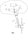
- a ram air turbine 20 is illustrated in Figure 1 .
- a strut 22 is associated with a turbine 24 and a transmission housing 26.
- Turbine 24 includes blades 18.
- the ram air turbine may be mounted to the frame of an aircraft 23, shown schematically.
- rotation of the turbine 24 generates electricity at a generator 28 in a known manner. This electricity may be used for any number of uses associated with the aircraft 27.
- the ram air turbine 20 may pivot at point 25 between a stowed position and a deployed position and driven by an actuator 11. As mentioned above, the ram air turbine may be moved to the deployed position from the stowed position when its use is desired.
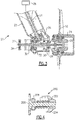
- FIG. 2A shows a detail of the ram air turbine 20.
- counterweights 29 are associated with the turbine 24.
- the counterweights control the pitch of blades 18 on the turbine 24 in response to speed.
- a transmission shaft 30 rotates with turbine 24.
- a bevel gear 32 is driven by the shaft 26 and drives an associated bevel gear 34 on an output shaft 36 in the strut 22.
- the output shaft 36 extends to the generator 28 (or other power sources, such as a pump), as known.
- governor springs 38 operate against the plate 31 and hold a governor rod 39 to the left in this figure.
- the counterweights 29 also act on the endplate 31 and against the force of the spring 38.
- a housing 37 surrounds the springs 38 and also rotates.
- the governor rod 39 is caused to move axially against the force of the governor spring 38 when the counterweights move in a direction to change the pitch angle from fine pitch to coarse pitch.
- Figure 2B schematically shows the interaction between the governor weights 29 and the governor rod 39.
- the blades 18 are held at a more open position.
- the counterweights rotate, and in turn drive the blades 18 to a more coarse position.
- Figure 2B shows this interaction, with a cam plate 103 which moves with the governor rod 39, and offset cam followers 102 which are a part of the counterweight 29 and the blades.
- a pivot axis X of the blades 108 is shown.
- the groove and cam plate 103 is part of the governor rod 39.
- the pins, which are illustrated at 100 and 102, move as the governor weights pivot.
- the governor weights 29 and blades 18 move as one such that as the pins move from the position 100 to the position 102, the angle of the blades 18 changes about the axis X.
- the associated spring positions 100S and 102S are also shown.
- the pins move from the position 100, which achieves a relatively open position of the blades 18, and as speed increases, they are moved to position 102, to pivot the blades 18 to a more closed position.
- the basic movement of the governor weights 29, blades 18, and governor rod 39 is generally as known, other than the location of the springs and addition of the governor rod, and the fact that the governor rod extends beyond the strut 22.
- the springs were on the forward end of the turbine 24 away from the strut 22.
- This arrangement located the center of gravity further from the mounting point of strut 22, and potentially diminished separation between an operating speed and a natural frequency.
- the center of gravity is optimized and the natural frequency separation is increased.
- smaller bearings and an overall reduction in mass may be achieved.
- the spring 38 mass is moved closer to the strut 22 as opposed to the prior art wherein the spring was further away. This reduces overhung mass and turbine imbalance issues that are associated with the spring changing position during governing.
- governor rod 39 extends from the turbine 24 axially beyond the output shaft 36 and the strut 22 and to a plate 31.
- the spring 38 acts against the plate 31 and is also positioned about the transmission shaft 30.
- the governor rod 39 extends along an axis which is generally co-axial to the propeller axis of rotation.
- the output shaft 36 extends along an axis which is non-perpendicular to the axis of rotation.
- Figure 3 shows a ram air turbine where numerals common to Figure 2A are used.
- the ram air turbine 100 of Figure 3 eliminates the outer housing 37 surrounding the spring 38. Endplate 31 is still used.
- the governor spring 38 acts against the plate 31, but is generally exposed radially outwardly of the transmission shaft. This has the potential benefits of making service and adjustment easier as well as reduced weight.
- Figure 4 shows an embodiment of the invention 200.
- the governor rod 204 extends through a fixed housing portion 202 and through the governor spring 210.
- An endplate 206 is still fixed to the rod 204.
- Bearing 208 supports the spring 210 on the plate 206 such that the spring 210 need not rotate.
- the other end of the spring is fixed to ground housing portion 202, which is a stationary portion. This may reduce issues with regard to the stability, frequency, and vibration of the ram air turbine.
Landscapes
- Engineering & Computer Science (AREA)
- Mechanical Engineering (AREA)
- General Engineering & Computer Science (AREA)
- Chemical & Material Sciences (AREA)
- Combustion & Propulsion (AREA)
- Sustainable Development (AREA)
- Life Sciences & Earth Sciences (AREA)
- Sustainable Energy (AREA)
- Aviation & Aerospace Engineering (AREA)
- Physics & Mathematics (AREA)
- Fluid Mechanics (AREA)
- Transmission Devices (AREA)
- Turbine Rotor Nozzle Sealing (AREA)
- Control Of Turbines (AREA)
- Connection Of Motors, Electrical Generators, Mechanical Devices, And The Like (AREA)
Claims (7)
- Stauluftturbine, die Folgendes umfasst:ein erstes Zahnrad;ein zweites Zahnrad;eine Ausgangswelle (36);eine Getriebewelle (30);eine Strebe (22);eine Turbine (24), die Turbinenschaufeln (18) umfasst, die verbunden sind, um die Getriebewelle (30) zu drehen, wobei die Getriebewelle verbunden ist, um das erste Zahnrad anzutreiben, das in Eingriff tritt, um das zweite Zahnrad anzutreiben, wobei das zweite Zahnrad verbunden ist, um die Ausgangswelle zu drehen, die sich durch die Strebe (22) von der Getriebewelle weg erstreckt; undeine Regleranordnung, um einen Anstellwinkel der Schaufeln in Reaktion auf eine Drehzahl zu ändern, und beinhaltend Gegengewichte (29), die auf eine Reglerfeder (38, 210) in der Regleranordnung wirken, wobei die Reglerfeder auf einer gegenüberliegenden Seite der Strebe relativ zu der Turbine positioniert ist;wobei die Reglerfeder abseits einer Platte (31, 206) an einem gegenüberliegenden Ende einer Reglerstange (39, 204) relativ zu der Turbine reagiert; undwobei sich die Reglerstange (39, 204) von der Turbine (24) axial über die Ausgangswelle (36) und die Strebe (22) innerhalb der Reglerfeder (38, 210) hinaus und zu der Platte (31, 206) erstreckt, wobei die Reglerstange (39, 204) mit der Platte (31, 206) dreht und die Reglerfeder (38, 210) eine Kraft gegen die Platte aufbringt, dadurch gekennzeichnet, dass ein Lager (208) die Reglerfeder an der Platte lagert, sodass die Reglerfeder nicht drehen muss.
- Stauluftturbine nach Anspruch 1, wobei die Reglerfeder (38, 210) mit der Getriebewelle (30) dreht.
- Stauluftturbine nach einem der vorstehenden Ansprüche, wobei sich die Getriebewelle (30) entlang einer Achse erstreckt, die koaxial zu einer Rotationsachse der Turbine ist, und sich die Ausgangswelle (36) entlang einer Achse erstreckt, die nicht rechtwinklig zu der Achse der Rotation ist.
- Stauluftturbine nach einem der vorstehenden Ansprüche, wobei das erste und zweite Zahnrad ein Paar von Kegelrädern (32) beinhalten.
- Stauluftturbine nach Anspruch 1 oder einem davon abhängigen Anspruch, wobei die Reglerfeder (38, 210) gegen die Platte (31, 206) wirkt, aber die Reglerfeder radial auswärts im Allgemeinen freiliegend ist.
- Stauluftturbine nach Anspruch 1 oder einem der Ansprüche 3 bis 5, wenn diese nicht von Anspruch 2 abhängig sind, wobei die Reglerfeder (31) nicht mit der Getriebewelle (30) dreht.
- Stauluftturbine nach einem der vorstehenden Ansprüche, wobei die Reglerstange (39, 204) veranlasst wird, sich axial gegen die Kraft der Reglerfeder (38, 210) zu bewegen, wenn sich die Gegengewichte (29) in einer Richtung bewegen, um den Anstellwinkel von kleiner Steigung zu großer Steigung zu ändern.
Applications Claiming Priority (1)
| Application Number | Priority Date | Filing Date | Title |
|---|---|---|---|
| US15/627,744 US10738761B2 (en) | 2017-06-20 | 2017-06-20 | Ram air turbine governor spring positioning |
Publications (2)
| Publication Number | Publication Date |
|---|---|
| EP3418203A1 EP3418203A1 (de) | 2018-12-26 |
| EP3418203B1 true EP3418203B1 (de) | 2022-01-12 |
Family
ID=62784008
Family Applications (1)
| Application Number | Title | Priority Date | Filing Date |
|---|---|---|---|
| EP18178827.4A Active EP3418203B1 (de) | 2017-06-20 | 2018-06-20 | Stauluftturbinenreglerfederpositionierung |
Country Status (2)
| Country | Link |
|---|---|
| US (1) | US10738761B2 (de) |
| EP (1) | EP3418203B1 (de) |
Families Citing this family (2)
| Publication number | Priority date | Publication date | Assignee | Title |
|---|---|---|---|---|
| US11465769B2 (en) * | 2018-01-11 | 2022-10-11 | Hamilton Sundstrand Corporation | Electric aircraft having ram air turbines |
| US12162585B2 (en) * | 2023-03-17 | 2024-12-10 | Northrop Grumman Systems Corporation | Passive rotor pitch control system |
Citations (1)
| Publication number | Priority date | Publication date | Assignee | Title |
|---|---|---|---|---|
| US2550229A (en) * | 1946-08-26 | 1951-04-24 | All American Airways Inc | Air-driven impeller |
Family Cites Families (13)
| Publication number | Priority date | Publication date | Assignee | Title |
|---|---|---|---|---|
| US2815188A (en) * | 1954-01-11 | 1957-12-03 | Marquardt Aircraft Co | Auxiliary power unit |
| US2988327A (en) * | 1956-02-03 | 1961-06-13 | Plessey Co Ltd | Emergency power systems for aircraft auxiliary apparatus |
| GB1074736A (en) * | 1964-09-09 | 1967-07-05 | Dowty Rotol Ltd | Wind motors |
| US3635583A (en) | 1968-11-15 | 1972-01-18 | Dowty Rotol Ltd | Ram-air turbines |
| US4411596A (en) * | 1980-03-25 | 1983-10-25 | Sundstrand Corporation | Ram air turbine control system |
| US4743163A (en) * | 1985-11-22 | 1988-05-10 | Sundstrand Corporation | Ram air turbine control system |
| US4991796A (en) * | 1988-11-14 | 1991-02-12 | Sundstrand Corporation | Ram air turbine drive system |
| US5562417A (en) | 1994-08-10 | 1996-10-08 | Sundstrand Corporation | Control mechanism for RAM air turbine |
| US7296970B2 (en) | 2005-06-08 | 2007-11-20 | Hamilton Sundstrand Corporation | Ram air turbine speed sensing ball detent over-speed prevention mechanism |
| US8066481B2 (en) | 2009-04-20 | 2011-11-29 | Hamilton Sundstrand Corporation | Balancing a ram air turbine |
| US9045983B2 (en) | 2010-10-19 | 2015-06-02 | Hamilton Sundstrand Corporation | Turbine yokeplate flyweights to improve RAT startup |
| US8876474B2 (en) | 2010-11-04 | 2014-11-04 | Hamilton Sundstrand Corporation | Ram air turbine startup |
| US9598980B2 (en) | 2012-04-27 | 2017-03-21 | Hamilton Sundstrand Corporation | Turbine lock plunger for ram air turbine assembly |
-
2017
- 2017-06-20 US US15/627,744 patent/US10738761B2/en active Active
-
2018
- 2018-06-20 EP EP18178827.4A patent/EP3418203B1/de active Active
Patent Citations (1)
| Publication number | Priority date | Publication date | Assignee | Title |
|---|---|---|---|---|
| US2550229A (en) * | 1946-08-26 | 1951-04-24 | All American Airways Inc | Air-driven impeller |
Also Published As
| Publication number | Publication date |
|---|---|
| US20180363626A1 (en) | 2018-12-20 |
| US10738761B2 (en) | 2020-08-11 |
| EP3418203A1 (de) | 2018-12-26 |
Similar Documents
| Publication | Publication Date | Title |
|---|---|---|
| US20240391583A1 (en) | Propeller control system for an aircraft | |
| US20120328436A1 (en) | Electromechanical actuator driven governor for ram air turbine | |
| EP3712058B1 (de) | Kombiniertes überdrehzahl-, segelstellungs- und reverse-enabler-steuerungsventil für eine propelleranordnung | |
| US4411596A (en) | Ram air turbine control system | |
| US9884675B2 (en) | System for changing the pitch of the blades of a propeller | |
| EP0247176A1 (de) | Regelsystem für eine stauluftturbine | |
| CN102448819B (zh) | 一种控制涡轮螺旋桨发动机风扇叶片的螺距的活动式执行机构 | |
| US20110182715A1 (en) | Adjusting device for variable guide vanes and method of operation | |
| CN102448818A (zh) | 用于控制涡桨发动机风扇叶片节距的装置 | |
| CN108473195A (zh) | 用于控制涡轮发动机风扇叶片桨距的具有顺桨锁定栓的系统 | |
| EP3418203B1 (de) | Stauluftturbinenreglerfederpositionierung | |
| EP0629165B1 (de) | In axialer richtung kompakte stauluftturbine | |
| US5286166A (en) | Automatic centrifugal force variable pitch propeller | |
| US10036262B2 (en) | Turbomachine impellor rotor with device for feathering the blades of the impellor | |
| CN111661348A (zh) | 推进器速度超调防止逻辑 | |
| US9598980B2 (en) | Turbine lock plunger for ram air turbine assembly | |
| US20120107119A1 (en) | Partial coarse pitch start ram air turbine with enhanced spring support | |
| US11124287B2 (en) | Fan module with variable-pitch blades for a turbomachine | |
| GB2072271A (en) | Ram air turbine blade pitch control mechanism | |
| GB2257477A (en) | Auxiliary power equipment | |
| US9045983B2 (en) | Turbine yokeplate flyweights to improve RAT startup | |
| RU2364754C1 (ru) | Компрессор двухконтурного газотурбинного двигателя | |
| CN119604455A (zh) | 具有包括行星滚子螺钉的桨距锁定装置的桨距改变机构 | |
| EP3882133A1 (de) | Schaufelwinkelbetätigungsmechanismus | |
| GB2151712A (en) | Ram air turbine |
Legal Events
| Date | Code | Title | Description |
|---|---|---|---|
| PUAI | Public reference made under article 153(3) epc to a published international application that has entered the european phase |
Free format text: ORIGINAL CODE: 0009012 |
|
| STAA | Information on the status of an ep patent application or granted ep patent |
Free format text: STATUS: THE APPLICATION HAS BEEN PUBLISHED |
|
| AK | Designated contracting states |
Kind code of ref document: A1 Designated state(s): AL AT BE BG CH CY CZ DE DK EE ES FI FR GB GR HR HU IE IS IT LI LT LU LV MC MK MT NL NO PL PT RO RS SE SI SK SM TR |
|
| AX | Request for extension of the european patent |
Extension state: BA ME |
|
| STAA | Information on the status of an ep patent application or granted ep patent |
Free format text: STATUS: REQUEST FOR EXAMINATION WAS MADE |
|
| 17P | Request for examination filed |
Effective date: 20190626 |
|
| RBV | Designated contracting states (corrected) |
Designated state(s): AL AT BE BG CH CY CZ DE DK EE ES FI FR GB GR HR HU IE IS IT LI LT LU LV MC MK MT NL NO PL PT RO RS SE SI SK SM TR |
|
| STAA | Information on the status of an ep patent application or granted ep patent |
Free format text: STATUS: EXAMINATION IS IN PROGRESS |
|
| 17Q | First examination report despatched |
Effective date: 20200518 |
|
| GRAP | Despatch of communication of intention to grant a patent |
Free format text: ORIGINAL CODE: EPIDOSNIGR1 |
|
| STAA | Information on the status of an ep patent application or granted ep patent |
Free format text: STATUS: GRANT OF PATENT IS INTENDED |
|
| INTG | Intention to grant announced |
Effective date: 20210903 |
|
| RIN1 | Information on inventor provided before grant (corrected) |
Inventor name: BAINES, ANDREW N. |
|
| GRAS | Grant fee paid |
Free format text: ORIGINAL CODE: EPIDOSNIGR3 |
|
| GRAA | (expected) grant |
Free format text: ORIGINAL CODE: 0009210 |
|
| STAA | Information on the status of an ep patent application or granted ep patent |
Free format text: STATUS: THE PATENT HAS BEEN GRANTED |
|
| AK | Designated contracting states |
Kind code of ref document: B1 Designated state(s): AL AT BE BG CH CY CZ DE DK EE ES FI FR GB GR HR HU IE IS IT LI LT LU LV MC MK MT NL NO PL PT RO RS SE SI SK SM TR |
|
| REG | Reference to a national code |
Ref country code: GB Ref legal event code: FG4D |
|
| REG | Reference to a national code |
Ref country code: CH Ref legal event code: EP |
|
| REG | Reference to a national code |
Ref country code: DE Ref legal event code: R096 Ref document number: 602018029431 Country of ref document: DE |
|
| REG | Reference to a national code |
Ref country code: IE Ref legal event code: FG4D |
|
| REG | Reference to a national code |
Ref country code: AT Ref legal event code: REF Ref document number: 1462222 Country of ref document: AT Kind code of ref document: T Effective date: 20220215 |
|
| REG | Reference to a national code |
Ref country code: LT Ref legal event code: MG9D |
|
| REG | Reference to a national code |
Ref country code: NL Ref legal event code: MP Effective date: 20220112 |
|
| REG | Reference to a national code |
Ref country code: AT Ref legal event code: MK05 Ref document number: 1462222 Country of ref document: AT Kind code of ref document: T Effective date: 20220112 |
|
| PG25 | Lapsed in a contracting state [announced via postgrant information from national office to epo] |
Ref country code: NL Free format text: LAPSE BECAUSE OF FAILURE TO SUBMIT A TRANSLATION OF THE DESCRIPTION OR TO PAY THE FEE WITHIN THE PRESCRIBED TIME-LIMIT Effective date: 20220112 |
|
| PG25 | Lapsed in a contracting state [announced via postgrant information from national office to epo] |
Ref country code: SE Free format text: LAPSE BECAUSE OF FAILURE TO SUBMIT A TRANSLATION OF THE DESCRIPTION OR TO PAY THE FEE WITHIN THE PRESCRIBED TIME-LIMIT Effective date: 20220112 Ref country code: RS Free format text: LAPSE BECAUSE OF FAILURE TO SUBMIT A TRANSLATION OF THE DESCRIPTION OR TO PAY THE FEE WITHIN THE PRESCRIBED TIME-LIMIT Effective date: 20220112 Ref country code: PT Free format text: LAPSE BECAUSE OF FAILURE TO SUBMIT A TRANSLATION OF THE DESCRIPTION OR TO PAY THE FEE WITHIN THE PRESCRIBED TIME-LIMIT Effective date: 20220512 Ref country code: NO Free format text: LAPSE BECAUSE OF FAILURE TO SUBMIT A TRANSLATION OF THE DESCRIPTION OR TO PAY THE FEE WITHIN THE PRESCRIBED TIME-LIMIT Effective date: 20220412 Ref country code: LT Free format text: LAPSE BECAUSE OF FAILURE TO SUBMIT A TRANSLATION OF THE DESCRIPTION OR TO PAY THE FEE WITHIN THE PRESCRIBED TIME-LIMIT Effective date: 20220112 Ref country code: HR Free format text: LAPSE BECAUSE OF FAILURE TO SUBMIT A TRANSLATION OF THE DESCRIPTION OR TO PAY THE FEE WITHIN THE PRESCRIBED TIME-LIMIT Effective date: 20220112 Ref country code: ES Free format text: LAPSE BECAUSE OF FAILURE TO SUBMIT A TRANSLATION OF THE DESCRIPTION OR TO PAY THE FEE WITHIN THE PRESCRIBED TIME-LIMIT Effective date: 20220112 Ref country code: BG Free format text: LAPSE BECAUSE OF FAILURE TO SUBMIT A TRANSLATION OF THE DESCRIPTION OR TO PAY THE FEE WITHIN THE PRESCRIBED TIME-LIMIT Effective date: 20220412 |
|
| PG25 | Lapsed in a contracting state [announced via postgrant information from national office to epo] |
Ref country code: PL Free format text: LAPSE BECAUSE OF FAILURE TO SUBMIT A TRANSLATION OF THE DESCRIPTION OR TO PAY THE FEE WITHIN THE PRESCRIBED TIME-LIMIT Effective date: 20220112 Ref country code: LV Free format text: LAPSE BECAUSE OF FAILURE TO SUBMIT A TRANSLATION OF THE DESCRIPTION OR TO PAY THE FEE WITHIN THE PRESCRIBED TIME-LIMIT Effective date: 20220112 Ref country code: GR Free format text: LAPSE BECAUSE OF FAILURE TO SUBMIT A TRANSLATION OF THE DESCRIPTION OR TO PAY THE FEE WITHIN THE PRESCRIBED TIME-LIMIT Effective date: 20220413 Ref country code: FI Free format text: LAPSE BECAUSE OF FAILURE TO SUBMIT A TRANSLATION OF THE DESCRIPTION OR TO PAY THE FEE WITHIN THE PRESCRIBED TIME-LIMIT Effective date: 20220112 Ref country code: AT Free format text: LAPSE BECAUSE OF FAILURE TO SUBMIT A TRANSLATION OF THE DESCRIPTION OR TO PAY THE FEE WITHIN THE PRESCRIBED TIME-LIMIT Effective date: 20220112 |
|
| PG25 | Lapsed in a contracting state [announced via postgrant information from national office to epo] |
Ref country code: IS Free format text: LAPSE BECAUSE OF FAILURE TO SUBMIT A TRANSLATION OF THE DESCRIPTION OR TO PAY THE FEE WITHIN THE PRESCRIBED TIME-LIMIT Effective date: 20220512 |
|
| REG | Reference to a national code |
Ref country code: DE Ref legal event code: R097 Ref document number: 602018029431 Country of ref document: DE |
|
| PG25 | Lapsed in a contracting state [announced via postgrant information from national office to epo] |
Ref country code: SM Free format text: LAPSE BECAUSE OF FAILURE TO SUBMIT A TRANSLATION OF THE DESCRIPTION OR TO PAY THE FEE WITHIN THE PRESCRIBED TIME-LIMIT Effective date: 20220112 Ref country code: SK Free format text: LAPSE BECAUSE OF FAILURE TO SUBMIT A TRANSLATION OF THE DESCRIPTION OR TO PAY THE FEE WITHIN THE PRESCRIBED TIME-LIMIT Effective date: 20220112 Ref country code: RO Free format text: LAPSE BECAUSE OF FAILURE TO SUBMIT A TRANSLATION OF THE DESCRIPTION OR TO PAY THE FEE WITHIN THE PRESCRIBED TIME-LIMIT Effective date: 20220112 Ref country code: EE Free format text: LAPSE BECAUSE OF FAILURE TO SUBMIT A TRANSLATION OF THE DESCRIPTION OR TO PAY THE FEE WITHIN THE PRESCRIBED TIME-LIMIT Effective date: 20220112 Ref country code: DK Free format text: LAPSE BECAUSE OF FAILURE TO SUBMIT A TRANSLATION OF THE DESCRIPTION OR TO PAY THE FEE WITHIN THE PRESCRIBED TIME-LIMIT Effective date: 20220112 Ref country code: CZ Free format text: LAPSE BECAUSE OF FAILURE TO SUBMIT A TRANSLATION OF THE DESCRIPTION OR TO PAY THE FEE WITHIN THE PRESCRIBED TIME-LIMIT Effective date: 20220112 |
|
| PLBE | No opposition filed within time limit |
Free format text: ORIGINAL CODE: 0009261 |
|
| STAA | Information on the status of an ep patent application or granted ep patent |
Free format text: STATUS: NO OPPOSITION FILED WITHIN TIME LIMIT |
|
| PG25 | Lapsed in a contracting state [announced via postgrant information from national office to epo] |
Ref country code: AL Free format text: LAPSE BECAUSE OF FAILURE TO SUBMIT A TRANSLATION OF THE DESCRIPTION OR TO PAY THE FEE WITHIN THE PRESCRIBED TIME-LIMIT Effective date: 20220112 |
|
| 26N | No opposition filed |
Effective date: 20221013 |
|
| PG25 | Lapsed in a contracting state [announced via postgrant information from national office to epo] |
Ref country code: MC Free format text: LAPSE BECAUSE OF FAILURE TO SUBMIT A TRANSLATION OF THE DESCRIPTION OR TO PAY THE FEE WITHIN THE PRESCRIBED TIME-LIMIT Effective date: 20220112 |
|
| REG | Reference to a national code |
Ref country code: CH Ref legal event code: PL |
|
| REG | Reference to a national code |
Ref country code: BE Ref legal event code: MM Effective date: 20220630 |
|
| PG25 | Lapsed in a contracting state [announced via postgrant information from national office to epo] |
Ref country code: SI Free format text: LAPSE BECAUSE OF FAILURE TO SUBMIT A TRANSLATION OF THE DESCRIPTION OR TO PAY THE FEE WITHIN THE PRESCRIBED TIME-LIMIT Effective date: 20220112 |
|
| PG25 | Lapsed in a contracting state [announced via postgrant information from national office to epo] |
Ref country code: LU Free format text: LAPSE BECAUSE OF NON-PAYMENT OF DUE FEES Effective date: 20220620 Ref country code: LI Free format text: LAPSE BECAUSE OF NON-PAYMENT OF DUE FEES Effective date: 20220630 Ref country code: IE Free format text: LAPSE BECAUSE OF NON-PAYMENT OF DUE FEES Effective date: 20220620 Ref country code: CH Free format text: LAPSE BECAUSE OF NON-PAYMENT OF DUE FEES Effective date: 20220630 |
|
| PG25 | Lapsed in a contracting state [announced via postgrant information from national office to epo] |
Ref country code: BE Free format text: LAPSE BECAUSE OF NON-PAYMENT OF DUE FEES Effective date: 20220630 |
|
| P01 | Opt-out of the competence of the unified patent court (upc) registered |
Effective date: 20230522 |
|
| PG25 | Lapsed in a contracting state [announced via postgrant information from national office to epo] |
Ref country code: IT Free format text: LAPSE BECAUSE OF FAILURE TO SUBMIT A TRANSLATION OF THE DESCRIPTION OR TO PAY THE FEE WITHIN THE PRESCRIBED TIME-LIMIT Effective date: 20220112 |
|
| PG25 | Lapsed in a contracting state [announced via postgrant information from national office to epo] |
Ref country code: HU Free format text: LAPSE BECAUSE OF FAILURE TO SUBMIT A TRANSLATION OF THE DESCRIPTION OR TO PAY THE FEE WITHIN THE PRESCRIBED TIME-LIMIT; INVALID AB INITIO Effective date: 20180620 |
|
| PG25 | Lapsed in a contracting state [announced via postgrant information from national office to epo] |
Ref country code: MK Free format text: LAPSE BECAUSE OF FAILURE TO SUBMIT A TRANSLATION OF THE DESCRIPTION OR TO PAY THE FEE WITHIN THE PRESCRIBED TIME-LIMIT Effective date: 20220112 Ref country code: CY Free format text: LAPSE BECAUSE OF FAILURE TO SUBMIT A TRANSLATION OF THE DESCRIPTION OR TO PAY THE FEE WITHIN THE PRESCRIBED TIME-LIMIT Effective date: 20220112 |
|
| PG25 | Lapsed in a contracting state [announced via postgrant information from national office to epo] |
Ref country code: TR Free format text: LAPSE BECAUSE OF FAILURE TO SUBMIT A TRANSLATION OF THE DESCRIPTION OR TO PAY THE FEE WITHIN THE PRESCRIBED TIME-LIMIT Effective date: 20220112 |
|
| PG25 | Lapsed in a contracting state [announced via postgrant information from national office to epo] |
Ref country code: MT Free format text: LAPSE BECAUSE OF FAILURE TO SUBMIT A TRANSLATION OF THE DESCRIPTION OR TO PAY THE FEE WITHIN THE PRESCRIBED TIME-LIMIT Effective date: 20220112 |
|
| PGFP | Annual fee paid to national office [announced via postgrant information from national office to epo] |
Ref country code: DE Payment date: 20250520 Year of fee payment: 8 |
|
| PGFP | Annual fee paid to national office [announced via postgrant information from national office to epo] |
Ref country code: GB Payment date: 20250520 Year of fee payment: 8 |
|
| PGFP | Annual fee paid to national office [announced via postgrant information from national office to epo] |
Ref country code: FR Payment date: 20250520 Year of fee payment: 8 |