EP3418199A1 - Air inlet for an aircraft engine nacelle and method of manufacturing such air inlet - Google Patents
Air inlet for an aircraft engine nacelle and method of manufacturing such air inlet Download PDFInfo
- Publication number
- EP3418199A1 EP3418199A1 EP18178051.1A EP18178051A EP3418199A1 EP 3418199 A1 EP3418199 A1 EP 3418199A1 EP 18178051 A EP18178051 A EP 18178051A EP 3418199 A1 EP3418199 A1 EP 3418199A1
- Authority
- EP
- European Patent Office
- Prior art keywords
- air inlet
- acoustic panel
- lip
- engine
- layer
- Prior art date
- Legal status (The legal status is an assumption and is not a legal conclusion. Google has not performed a legal analysis and makes no representation as to the accuracy of the status listed.)
- Granted
Links
- 238000004519 manufacturing process Methods 0.000 title claims description 23
- 239000002131 composite material Substances 0.000 claims abstract description 16
- 238000010030 laminating Methods 0.000 claims description 18
- 238000000034 method Methods 0.000 claims description 17
- 230000006641 stabilisation Effects 0.000 claims description 12
- 238000011105 stabilization Methods 0.000 claims description 12
- 239000010410 layer Substances 0.000 description 68
- 238000005265 energy consumption Methods 0.000 description 6
- 238000005516 engineering process Methods 0.000 description 5
- 239000000446 fuel Substances 0.000 description 5
- 238000010438 heat treatment Methods 0.000 description 4
- 239000011159 matrix material Substances 0.000 description 4
- 239000002184 metal Substances 0.000 description 4
- 238000005192 partition Methods 0.000 description 4
- 238000006116 polymerization reaction Methods 0.000 description 4
- 230000002787 reinforcement Effects 0.000 description 4
- XLYOFNOQVPJJNP-UHFFFAOYSA-N water Chemical compound O XLYOFNOQVPJJNP-UHFFFAOYSA-N 0.000 description 4
- 239000012790 adhesive layer Substances 0.000 description 3
- 230000008030 elimination Effects 0.000 description 3
- 238000003379 elimination reaction Methods 0.000 description 3
- 229920000647 polyepoxide Polymers 0.000 description 3
- 229920005992 thermoplastic resin Polymers 0.000 description 3
- 229920001187 thermosetting polymer Polymers 0.000 description 3
- 229920000049 Carbon (fiber) Polymers 0.000 description 2
- 239000004593 Epoxy Substances 0.000 description 2
- 230000015572 biosynthetic process Effects 0.000 description 2
- 239000004917 carbon fiber Substances 0.000 description 2
- 238000007710 freezing Methods 0.000 description 2
- 239000000463 material Substances 0.000 description 2
- 239000007769 metal material Substances 0.000 description 2
- 229920005989 resin Polymers 0.000 description 2
- 239000011347 resin Substances 0.000 description 2
- 238000007493 shaping process Methods 0.000 description 2
- 238000004073 vulcanization Methods 0.000 description 2
- 230000000740 bleeding effect Effects 0.000 description 1
- 238000004891 communication Methods 0.000 description 1
- 238000013016 damping Methods 0.000 description 1
- 230000007423 decrease Effects 0.000 description 1
- 230000001419 dependent effect Effects 0.000 description 1
- 230000000694 effects Effects 0.000 description 1
- 239000003822 epoxy resin Substances 0.000 description 1
- 230000008014 freezing Effects 0.000 description 1
- 239000003292 glue Substances 0.000 description 1
- 239000002905 metal composite material Substances 0.000 description 1
- 239000000203 mixture Substances 0.000 description 1
- 210000000056 organ Anatomy 0.000 description 1
- 239000002245 particle Substances 0.000 description 1
- 230000000379 polymerizing effect Effects 0.000 description 1
- 239000007787 solid Substances 0.000 description 1
- 238000001228 spectrum Methods 0.000 description 1
Images


Classifications
-
- B—PERFORMING OPERATIONS; TRANSPORTING
- B64—AIRCRAFT; AVIATION; COSMONAUTICS
- B64D—EQUIPMENT FOR FITTING IN OR TO AIRCRAFT; FLIGHT SUITS; PARACHUTES; ARRANGEMENT OR MOUNTING OF POWER PLANTS OR PROPULSION TRANSMISSIONS IN AIRCRAFT
- B64D33/00—Arrangements in aircraft of power plant parts or auxiliaries not otherwise provided for
- B64D33/02—Arrangements in aircraft of power plant parts or auxiliaries not otherwise provided for of combustion air intakes
-
- B—PERFORMING OPERATIONS; TRANSPORTING
- B64—AIRCRAFT; AVIATION; COSMONAUTICS
- B64D—EQUIPMENT FOR FITTING IN OR TO AIRCRAFT; FLIGHT SUITS; PARACHUTES; ARRANGEMENT OR MOUNTING OF POWER PLANTS OR PROPULSION TRANSMISSIONS IN AIRCRAFT
- B64D15/00—De-icing or preventing icing on exterior surfaces of aircraft
- B64D15/12—De-icing or preventing icing on exterior surfaces of aircraft by electric heating
-
- B—PERFORMING OPERATIONS; TRANSPORTING
- B64—AIRCRAFT; AVIATION; COSMONAUTICS
- B64F—GROUND OR AIRCRAFT-CARRIER-DECK INSTALLATIONS SPECIALLY ADAPTED FOR USE IN CONNECTION WITH AIRCRAFT; DESIGNING, MANUFACTURING, ASSEMBLING, CLEANING, MAINTAINING OR REPAIRING AIRCRAFT, NOT OTHERWISE PROVIDED FOR; HANDLING, TRANSPORTING, TESTING OR INSPECTING AIRCRAFT COMPONENTS, NOT OTHERWISE PROVIDED FOR
- B64F5/00—Designing, manufacturing, assembling, cleaning, maintaining or repairing aircraft, not otherwise provided for; Handling, transporting, testing or inspecting aircraft components, not otherwise provided for
- B64F5/10—Manufacturing or assembling aircraft, e.g. jigs therefor
-
- F—MECHANICAL ENGINEERING; LIGHTING; HEATING; WEAPONS; BLASTING
- F02—COMBUSTION ENGINES; HOT-GAS OR COMBUSTION-PRODUCT ENGINE PLANTS
- F02C—GAS-TURBINE PLANTS; AIR INTAKES FOR JET-PROPULSION PLANTS; CONTROLLING FUEL SUPPLY IN AIR-BREATHING JET-PROPULSION PLANTS
- F02C7/00—Features, components parts, details or accessories, not provided for in, or of interest apart form groups F02C1/00 - F02C6/00; Air intakes for jet-propulsion plants
- F02C7/04—Air intakes for gas-turbine plants or jet-propulsion plants
- F02C7/045—Air intakes for gas-turbine plants or jet-propulsion plants having provisions for noise suppression
-
- F—MECHANICAL ENGINEERING; LIGHTING; HEATING; WEAPONS; BLASTING
- F02—COMBUSTION ENGINES; HOT-GAS OR COMBUSTION-PRODUCT ENGINE PLANTS
- F02C—GAS-TURBINE PLANTS; AIR INTAKES FOR JET-PROPULSION PLANTS; CONTROLLING FUEL SUPPLY IN AIR-BREATHING JET-PROPULSION PLANTS
- F02C7/00—Features, components parts, details or accessories, not provided for in, or of interest apart form groups F02C1/00 - F02C6/00; Air intakes for jet-propulsion plants
- F02C7/04—Air intakes for gas-turbine plants or jet-propulsion plants
- F02C7/047—Heating to prevent icing
-
- B—PERFORMING OPERATIONS; TRANSPORTING
- B64—AIRCRAFT; AVIATION; COSMONAUTICS
- B64D—EQUIPMENT FOR FITTING IN OR TO AIRCRAFT; FLIGHT SUITS; PARACHUTES; ARRANGEMENT OR MOUNTING OF POWER PLANTS OR PROPULSION TRANSMISSIONS IN AIRCRAFT
- B64D33/00—Arrangements in aircraft of power plant parts or auxiliaries not otherwise provided for
- B64D33/02—Arrangements in aircraft of power plant parts or auxiliaries not otherwise provided for of combustion air intakes
- B64D2033/0206—Arrangements in aircraft of power plant parts or auxiliaries not otherwise provided for of combustion air intakes comprising noise reduction means, e.g. acoustic liners
-
- B—PERFORMING OPERATIONS; TRANSPORTING
- B64—AIRCRAFT; AVIATION; COSMONAUTICS
- B64D—EQUIPMENT FOR FITTING IN OR TO AIRCRAFT; FLIGHT SUITS; PARACHUTES; ARRANGEMENT OR MOUNTING OF POWER PLANTS OR PROPULSION TRANSMISSIONS IN AIRCRAFT
- B64D33/00—Arrangements in aircraft of power plant parts or auxiliaries not otherwise provided for
- B64D33/02—Arrangements in aircraft of power plant parts or auxiliaries not otherwise provided for of combustion air intakes
- B64D2033/0233—Arrangements in aircraft of power plant parts or auxiliaries not otherwise provided for of combustion air intakes comprising de-icing means
-
- F—MECHANICAL ENGINEERING; LIGHTING; HEATING; WEAPONS; BLASTING
- F05—INDEXING SCHEMES RELATING TO ENGINES OR PUMPS IN VARIOUS SUBCLASSES OF CLASSES F01-F04
- F05D—INDEXING SCHEME FOR ASPECTS RELATING TO NON-POSITIVE-DISPLACEMENT MACHINES OR ENGINES, GAS-TURBINES OR JET-PROPULSION PLANTS
- F05D2260/00—Function
- F05D2260/96—Preventing, counteracting or reducing vibration or noise
Definitions
- the invention relates to an air inlet for a nacelle of an engine aircraft.
- the air inlet according to the invention is manufactured as one single piece, in particular using composite materials, more in particular with one single stabilization cycle, for example in autoclave, implementing a procedure which is known in the field as co-curing.
- the air inlet of a nacelle currently consists of the following components: an engine ring, an acoustic panel, which, in turn, commonly comprises two or three pieces, a lip, an outer barrel, which, in turn, commonly comprises two or three pieces, and a plurality of partitions and reinforcements.
- an engine ring which, in turn, commonly comprises two or three pieces, a lip
- an outer barrel which, in turn, commonly comprises two or three pieces
- a plurality of partitions and reinforcements are manufactured individually, even with different materials, such as metal materials and composite materials, and then assembled together and joined to one another.
- the engine ring traditionally is a separate element, made of a metal material, and is fixed to the structure of the air inlet through screws and bolts.
- the acoustic panel normally consists of two or three properly positioned pieces of composite material or sheet metal pieces glued together and is fixed to the structure of the air inlet through mechanical fixing means, such as screws and bolts.
- a further technical problem concerns the formation of ice on the portions exposed to the air of the air inlet.
- Solutions are known, which allow manufacturers to place heating elements in the area of the surfaces subjected to the formation of ice.
- the adopted solutions are typically based on the bleeding of hot air from the engines and on the following directing thereof towards the area of interest through metal pipes. This solution is affected by some limits concerning the weight of the system, which necessarily needs to be made of metal, the high temperatures involved and the general low efficiency of the system.
- the object of the invention is to solve the aforesaid technical problems as well as other problems by providing an air inlet for a nacelle manufactured as one single piece, in particular in one single body.
- An aspect of the invention relates to an air inlet for nacelles having the features set forth in appended claim 1.
- a further aspect of the invention relates to a nacelle having the features set forth in appended claim 7.
- a further aspect of the invention relates to a process for manufacturing an air inlet having the features set forth in appended claim 8.
- air inlet 3 is particularly adapted to be associated with a nacelle 2 for an aircraft 1.
- Air inlet 3 comprises: at least one acoustic panel 5, the latter being adapted to lower the noise generated by an engine 21 to which air inlet 3 can be connected; and at least one lip 6 defining the profile upon which an air flow can act, which is flowing into air inlet 3.
- Said air inlet 3 according to the invention is manufactured as one single piece, made of a composite material, in one single body.
- one single piece means that in air inlet 3 there are no joints between the parts comprised in the air inlet itself, in particular between the aforesaid parts and/or between the parts described below, thus creating one single body. More in general, there are no joints adapted to fix distinct parts of air inlet 3 to one another, in particular the aforesaid parts and/or the parts described below as comprised in air inlet 3.
- At least one acoustic panel 5 and at least one lip 6 of air inlet 3 are manufactured as one single piece, in one single body.
- an air inlet 3 By manufacturing an air inlet 3 as one single piece it is possible to eliminate joints between the parts of air inlet 3. This solution allows manufacturers to obtain a reduction in aerodynamic resistance and, as a consequence, a reduction in the consumption of fuel of engine 21 comprised in nacelle 2 of aircraft 1. Furthermore, it is possible to obtain laminar air flows on the structure, for the greatest part of the extension of the inner duct of air inlet 3.
- said at least one air inlet 3 comprises at least one outer barrel 7, which is adapted to define the outer shape of air inlet 3 upon which an air flow can act.
- Said air inlet 3 according to the invention is manufactured as one single piece, made of a composite material.
- At least one acoustic panel 5, at least one lip 6 and at least one outer barrel 7 of air inlet 3 are manufactured as one single piece, in one single body.
- an air inlet 3 By manufacturing an air inlet 3 in one single piece, it is possible to obtain laminar air flows on the structure, for the greatest part of the extension of outer barrel 7 and of the inner duct of air inlet 3.
- the invention allows manufacturers to eliminate joints between the parts of air inlet 3.
- This solution allows manufacturers to obtain a reduction in aerodynamic resistance and, as a consequence, a reduction in the consumption of fuel of engine 21 comprised in nacelle 2 of aircraft 1, since it leads to the creation of a laminar air flow, which extends over a large a part of outer barrel 7 and of the inner duct of air inlet 3, and, consequently, to improved airfoils thanks to the elimination of joints.
- said at least one air inlet 3 comprises at least one engine ring 4, which is adapted to allow air inlet 3 to be connected to an engine 21 of nacelle 2.
- Said air inlet 3 according to the invention is manufactured as one single piece, made of a composite material.
- At least one acoustic panel 5, at least one lip 6, at least one outer barrel 7 and/or at least one engine ring 4 of air inlet 3 are manufactured as one single piece, in one single body.
- the engine ring generally is a separate element, distinct from the rest of the air inlet and made of metal.
- engine ring 4 is entirely manufactured with the rest of the body of air inlet 3, made of a composite material, thus significantly reducing the weight of entire air inlet 3 as well as manufacturing and assembling costs.
- air inlet 3 is manufactured by means of one single stabilization cycle, for example by means of one single autoclave cycle, or one single oven cycle, or one single press cycle, depending on the material used for manufacturing air inlet 3.
- said acoustic panel 5 substantially extends from said engine ring 4 to said lip 6.
- air inlet 3 for it is manufactured as one single piece, it is possible to design a noise lowering device obtained by means of said acoustic panel 5, which can substantially extend along the entire longitudinal extension of air inlet 3.
- air inlet 3 allows the noise lowering surface to be increased, up to an increase thereof amounting to 70% or more compared to an air inlet consisting of discrete elements assembled together.
- this solution allows manufacturers to increase the area available for a noise lowering device and, in particular, to crate an acoustic panel 5.
- this solution allows manufacturers to create a noise lowering device extending up to the area of lip 6.
- Acoustic panel 5 comprised in air inlet 3 according to the invention creates a plurality of Helmholtz resonators, which allow noise to the lowered.
- the operating principle of an acoustic panel using the principle of Helmholtz resonators will not be described any further, as it is known to a person skilled in the art.
- the total noise lowering capacity of air inlet 3 is provided by acoustic panel 5 and by the process for manufacturing air inlet 3 itself. Indeed, this process allows manufacturers to produce acoustic devices, in particular acoustic panels 5, with high performances, as explained more in detail below. Acoustic panels 5 comprised in air inlet 3 have an acoustic impedance close to the calculated optimal value, so as to obtain the maximum noise damping possible.
- the optimal impedance varies based on the incident noise spectrum and on the air flow body in air inlet 3 and, therefore, it depends on the operating rpm of the engine.
- air inlet 3 for its is manufactured as one single piece using a composite material, comprising a front layer 3a, which defines an outer profile of air inlet 3 and is visible from the outside; a rear layer 3c, which defines an inner profile of air inlet 3 and it is not visible from the outside; and at least one intermediate layer 3b, which is incorporated between said two layers (3a, 3b).
- Said intermediate layer 3b is preferably made with a honeycomb structure.
- said acoustic panel 5 In the area of air inlet 3 where said intermediate layer 3b is located there can be obtained said acoustic panel 5, in particular by making holes in said front layer 3a, so as to create Helmholtz resonators.
- Intermediate layer 3b can also be used as stiffening structure for one or more portions of air inlet 3.
- air inlet 3 incorporates, in the structure of the air inlet itself, an anti-icing system 8.
- Said anti-icing system 8 is electric, for example a heating element, and is manufactured with an anti-freezing technology known as "running wet". This technology prevents water or water vapor from freezing on the surfaces, in particular on the surfaces subjected to an air flow.
- This anti-icing system 8 is more efficient from an energy consumption point of view, as it requires an electric power consumption compared to other technologies used for manufacturing anti-icing systems, such as for example the "fully evaporative" technology.
- said anti-icing system 8 is a heating element. Said heating element is obtained by means of a redundant electronic circuit.
- Anti-icing system 8 for it is electric and incorporated inside the structure of air inlet 3 and as it operates with a "running wet” technology, leads to a reduction in energy consumption and in the typical weight of traditional anti-icing systems.
- said anti-icing system 8 comprises a solid state redundant electronic circuit.
- the circuit as it comprises a plurality of connections or branches and redundant nodes, is intrinsically resistant to possible interruptions of a plurality of interconnections between the nodes, thus ensuring the continuity and functionality of the circuit even in the presence of multiple single interruptions of connections or branches of the same circuit, for example caused by holes, for example needed to create Helmholtz resonators.
- the continuity and functionality of the circuit is ensured for a high percentage, approximately 99.99% of the cases.
- the electric circuit is redundant because there is a plurality of paths adapted to lead an electric/electronic current between any two nodes.
- a second possible use of the circuit, besides the one as anti-icing system, is as communication line.
- the circuit can be used as electric energy or electric and/or electronic signal leading element, useful to manage and/or control sensors and/or actuators.
- said anti-icing system 8 is obtained by means of a system comprising a plasma actuator, which is suited to be incorporated in the structure of air inlet 3, especially relative to the air-exposed surface.
- Said plasma actuator is adapted to generate at least one plasma discharge adapted to create a flow of ionized hot air particles towards said air-exposed surface.
- Air inlet 3 is particularly adapted to be associated with a nacelle 2 for an aircraft 1.
- Nacelle 2 comprises an engine 21 and a containing structure 22, which is adapted to surround engine 21.
- Air inlet 3 according to the invention allows manufacturers to improve the performances of engine 21 and, in particular, to reduce consumptions. Indeed, air inlet 3 according to the invention reduces the fuel consumption of aircraft 1, thanks to the fact that air inlet 3 ensures a laminar air flow, in particular extending along a great part of outer barrel 7. Air inlet 3 according to the invention has improved aerodynamic efficiencies compared to currently known solutions because there are no more joints between the parts comprised in air inlet 3.
- a preferred embodiment of the process for manufacturing an air inlet 3 adapted to be applied to nacelles 2 preferably comprises the following steps, more preferably steps that take place one after the other:
- the step of laminating a front layer 3a involves shaping the layer of air inlet 3 which will be visible from the outside.
- the shape at least of lip 6 and, if necessary, also of outer barrel 7 and of engine ring 4 are defined.
- the shape will follow the designing specifications of air inlet 3.
- the shape of lip 6, of outer barrel 7 and of engine ring 4 is defined.
- this step properly involves shaping the front layer 3a, made of a composite material, in order to obtain the desired profile of air inlet 3, at least in the portion that has to be manufactured as one single piece.
- the visible profile of air inlet 3 is substantially similar to the theoretical designing profile, as there are no joints between the parts.
- Said front layer 3a preferably is made of a thermosetting matrix, for example an epoxy or thermoplastic resin matrix, with reinforcement carbon fibers.
- a redundant electronic circuit like the one described above is properly positioned.
- the shape of front layer 3a and, in particular, the composition and/or the thickness thereof, can vary in the different portions of air inlet 3, depending on the needs.
- the step of laminating a front layer 3a there is the step of assembling at least one intermediate layer 3b.
- the extension and the arrangement of acoustic panel 5 are defined.
- Said intermediate layer 3b preferably is a honeycomb structure.
- the shape and the dimensions of each single cell of intermediate layer 3b are intentionally designed so that it can be used as cavity for a Helmholtz resonator.
- Said intermediate layer 3b is placed on at least one portion of said front layer 3a.
- said intermediate layer 3b is arranged at least one all the portions of front layer 3a for which an acoustic panel 5 for air inlet 3 needs to be used.
- Said intermediate layer 3b can also be used, besides as component for manufacturing an acoustic panel 5, as reinforcement structure for the structure of air inlet 3. In this way, besides ensuring the desired stiffness and self-bearing ability in the proper areas of air inlet 3, there is a significant reduction of the total weight of air inlet 3.
- the shape of the cells of intermediate layer 3b can vary depending on the needs and based on the area of air inlet 3 where it has to be placed.
- an adhesive layer on intermediate layer 3b is for example a thermosetting resin, for example an epoxy resin, or a thermoplastic resin.
- said step of laminating a rear layer 3c allows manufacturers to properly shape rear layer 3c, made of a composite material, in order to obtain the inner profile of air inlet 3, which is not visible.
- Said rear layer 3c preferably is made of a thermosetting matrix, for example an epoxy or thermoplastic resin matrix, with reinforcement carbon fibers.
- both front layer 3a and rear layer 3c have not been processed, for example polymerized or vulcanized, yet and, therefore, the respective matrices are not stabilized yet, for example due to a stabilization cycle, such as an autoclave cycle or an oven cycle or a press cycle.
- a stabilization cycle such as an autoclave cycle or an oven cycle or a press cycle.
- the stabilization for example a polymerization or a vulcanization, only takes place when both front layer 3a and rear layer 3c have been properly laminated.
- the step of processing air inlet 3 is carried out by means of one single stabilization cycle, for example by means of an autoclave cycle.
- the invention envisages the execution of one single stabilization process, for example polymerization or vulcanization, for example by having the entire air inlet 3 undergo one single autoclave, oven or press cycle. Therefore, air inlet 3 is subjected to a process that can be defined as co-curing.
- the process according to the invention allows manufacturers to significantly reduce the times of the manufacturing cycles needed to produce air inlet 3.
- This step involves making holes in at least one portion of front layer 3a, so as to generate Helmholtz resonators.
- said portion of front layer 3a where the aforesaid holes are made is included in the portion of air inlet 3 where said intermediate layer 3b is positioned.
- Said plurality of holes are made in said front layer 3a in a mechanical manner, for example using perforation spindles with a single head or with a multiple head.
- the size and the distance of the holes depend, among other things, on the dimensions of each cell of intermediate layer 3b, in compliance with the specifications to be followed when manufacturing a Helmholtz resonator.
- the distance between the holes is proportionate to the dimensions of the cells of intermediate layer 3b.
- This solution allows manufacturers to obtain acoustic panel 5 with very high acoustic properties compared to an acoustic panel associated with an air inlet consisting of different parts assembled together in a mechanical manner, by means of joints.
- resulting acoustic panel 5 is characterized by ensuring that all generated holes are open, in particular are not obstructed by glues and/or resins, which is a typical problem affecting those manufacturing processes in which different polymerization steps are carried out and/or the step of making a plurality of holes takes place after the last polymerization step; therefore, the noise lowering performances of air inlet 3 according to the invention are improved.
- the area associated with a noise lowering device represented by acoustic panel 5 is maximized.
- the area where to create said acoustic panel 5 can be increased, for example by extending it up to lip 6, as shown for example in figure 2 .
- Air inlet 3 manufactured by means of the process according to the invention allows manufacturers to eliminate both structural discontinuities and acoustic discontinuities, thus improving the performances of air inlet 3.
- intermediate layer 3b comprises a porous partition glued between two honeycomb structures.
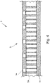
- Figure 1 shows, in an axonometric view, air inlet 3 according to the invention.
- the preferred embodiment of air inlet 3 is free from joints, in particular on front layer 3a of air inlet 3, i.e. front layer 3a described above upon which the air flow acts, thus creating an air flow that is highly laminar, which leads to all the advantages discussed above.
- the shape of air inlet 3 and, in particular, of lip 6 and of outer barrel 7 does not differ in any way from the ideal designed shape, thus overcoming possible structural limits present in air inlets according to the state of the art.
- Figure 2 shows air inlet 3 of figure 1 in a cross section view in an upper portion thereof.
- the cross section shows that there are no structural discontinuities from engine ring 4 up to outer barrel 7, for air inlet 3 is manufactured as one single piece.
- Figure 2 further shows the extension of acoustic panel 5, which, in the explanatory and non-limiting embodiment shown therein, starts from engine ring 4 and reaches lip 6.
- the figure further reveals how the anti-icing system can be incorporated in the structure of air inlet 3.
- Figure 2 also shows to a person skilled in the art that the profile of air inlet 3 can coincide with the theoretical designing profile, thus obtaining a laminar flow because there are no structural discontinuities that could create turbulences.
- figure 2 reveals to a person skilled in the art where the closing plates or partitions could be placed, so that the inner structure of air inlet 3 is inaccessible, and where possible flanged portions could be arranged in order to fix air inlet 3 to containing structure 22 of a nacelle 2.
- Said closing plates or partitions and flanged portions can be fitted to air inlet 3 in a following phase, for example based on the features of nacelle 2 to which air inlet 3 is to be applied.
- Figure 3 shows, in a cross section view, the air inlet 3 of an assembly with a nacelle 2 for an aircraft 1;
- the air inlet 3 according to the invention can be applied to an already existing nacelle 2, thus improving the performances of engine 21.
- Figure 4 shows, in a schematic cross-section view, a portion of a possible embodiment of acoustic panel 5 where front layer 3a, intermediate layer 3b and rear layer 3c are visible.
- the shape of the layers allows manufacturers to obtain a high-performance acoustic panel 5, which, for it is manufactured as one single piece with air inlet 3, in particular by means of the process described above, generates Helmholtz resonators, which lead to a noise lowering that is much greater than the ones that can be obtained with a combination of an acoustic panel assembled on an air inlet according to the state of the art.
- the one-piece configuration of air inlet 3 according to the invention allows manufacturers to eliminate all joints, in particular between lip 6 and outer barrel 7, thus reducing the difference from the theoretical designing profile.
- This joint-less profile ensures a laminar flow on the largest part possible of air inlet 3, thus offering improvements in terms of fuel consumptions of aircraft 1.
- air inlet 3 allows manufacturers to reduce energy consumption, both for the correct operation of air inlet 3 and for engine 21 of a nacelle 2 associated with air inlet 3.
- Air inlet 3 according to the invention preferably is entirely made of a composite material and is manufactured with a co-curing process substantially carried out by means of one single stabilization cycle.
- air inlet 3 All the main components of air inlet 3, in particular acoustic panel 5, lip 6 and, if necessary, outer barrel 7 and engine ring 4, are made of a composite material, thus creating on single body obtained by means of one single stabilization cycle.
- Air inlet 3 according to the invention has a small weight compared to currently known air inlets, thanks to the elimination of the greatest part of the joints and of the connections organs, besides being capable of integrating, in the structure of air inlet 3 itself, elements that, according to th state of the art, were fixed to the structure of the air inlet.
- Air inlet 3 according to the invention allows manufacturers to obtain an increase in the noise lowering capacity, for example as a consequence of the expansion of the acoustic area, i.e. of the dimensions of panel 5, thanks to the perforation of the inner edge of lip 6, i.e. of front layer 3a, which is made of a composite material.
- air inlet 3 according to the invention allows the surface adapted to lowering the noise to be increased, up to an increase thereof amounting to more than 70% compared to an air inlet consisting of discrete elements assembled together.
Landscapes
- Engineering & Computer Science (AREA)
- Chemical & Material Sciences (AREA)
- Combustion & Propulsion (AREA)
- Aviation & Aerospace Engineering (AREA)
- Manufacturing & Machinery (AREA)
- Mechanical Engineering (AREA)
- General Engineering & Computer Science (AREA)
- Transportation (AREA)
- Soundproofing, Sound Blocking, And Sound Damping (AREA)
- Structures Of Non-Positive Displacement Pumps (AREA)
- Exhaust Silencers (AREA)
Abstract
Description
- The invention relates to an air inlet for a nacelle of an engine aircraft.
- The air inlet according to the invention is manufactured as one single piece, in particular using composite materials, more in particular with one single stabilization cycle, for example in autoclave, implementing a procedure which is known in the field as co-curing.
- As it is known, the air inlet of a nacelle currently consists of the following components: an engine ring, an acoustic panel, which, in turn, commonly comprises two or three pieces, a lip, an outer barrel, which, in turn, commonly comprises two or three pieces, and a plurality of partitions and reinforcements. These components are manufactured individually, even with different materials, such as metal materials and composite materials, and then assembled together and joined to one another.
- For example, the engine ring traditionally is a separate element, made of a metal material, and is fixed to the structure of the air inlet through screws and bolts. The acoustic panel, on the other hand, normally consists of two or three properly positioned pieces of composite material or sheet metal pieces glued together and is fixed to the structure of the air inlet through mechanical fixing means, such as screws and bolts.
- The operations carried out to assembly the parts of the air inlet, besides increasing manufacturing costs, jeopardize the overall performances of the single elements making up the air inlet of the nacelle, especially in the portions joining the different parts.
- It is known, indeed, that the presence of joints between the lip and the outer barrel generates a difference between the airfoil of the air inlet and the theoretical designing airfoil due to manufacturing and assembling tolerances, thus creating discontinuities between the coupled surfaces, such as steps or openings. This difference generates disturbances in the air flow, which is not laminar any longer, hence increasing aerodynamic resistance and jeopardizing the performances of the aircraft.
- Therefore, market needs lead manufacturers to produce nacelles that are adapted to reduce energy consumption.
- Solutions are known, in which manufacturers tried to integrate some parts of the air inlet so as to reduce the number of elements to be assembled as well as aerodynamic resistance.
- These solutions, despite reducing manufacturing and energy consumption costs, are significantly outdone by the performances offered by the solution suggested by this invention.
- Furthermore, in the field there is the need to lower the noise generated by the engine assembly. Prior art solutions lack effectiveness on this matter, for their results jeopardize other aspects of the air inlet, such as for example weight and/or aerodynamic performances.
- A further technical problem concerns the formation of ice on the portions exposed to the air of the air inlet. Solutions are known, which allow manufacturers to place heating elements in the area of the surfaces subjected to the formation of ice. The adopted solutions are typically based on the bleeding of hot air from the engines and on the following directing thereof towards the area of interest through metal pipes. This solution is affected by some limits concerning the weight of the system, which necessarily needs to be made of metal, the high temperatures involved and the general low efficiency of the system.
- The object of the invention is to solve the aforesaid technical problems as well as other problems by providing an air inlet for a nacelle manufactured as one single piece, in particular in one single body.
- An aspect of the invention relates to an air inlet for nacelles having the features set forth in appended claim 1.
- A further aspect of the invention relates to a nacelle having the features set forth in appended claim 7.
- A further aspect of the invention relates to a process for manufacturing an air inlet having the features set forth in appended
claim 8. - The accessory features of the air inlet, of the assembly and of the process are disclosed in the appended dependent claims.
- The features and advantages of the air inlet, of the nacelle and of the process will be best understood upon perusal of the following description of possible non-limiting explanatory embodiments and of the accompanying drawings, which respectively show what follows:
-
figure 1 shows, in an axonometric view, a possible embodiment of the air inlet according to the present invention; -
figure 2 shows the air inlet offigure 1 in a cross section view in an upper portion thereof; -
figure 3 shows, in a cross section view, the air inlet of an assembly with a nacelle in an upper portion; -
figure 4 shows, in an axonometric cross section view, a portion of the acoustic panel comprised in the air inlet according to the invention. - With reference to the aforesaid figures,
air inlet 3 according to the invention is particularly adapted to be associated with a nacelle 2 for an aircraft 1. -
Air inlet 3 according to the invention comprises: at least oneacoustic panel 5, the latter being adapted to lower the noise generated by anengine 21 to whichair inlet 3 can be connected; and at least onelip 6 defining the profile upon which an air flow can act, which is flowing intoair inlet 3. - Said
air inlet 3 according to the invention is manufactured as one single piece, made of a composite material, in one single body. - For the purpose of this description, the term "one single piece" means that in
air inlet 3 there are no joints between the parts comprised in the air inlet itself, in particular between the aforesaid parts and/or between the parts described below, thus creating one single body. More in general, there are no joints adapted to fix distinct parts ofair inlet 3 to one another, in particular the aforesaid parts and/or the parts described below as comprised inair inlet 3. - Therefore, in this embodiment, at least one
acoustic panel 5 and at least onelip 6 ofair inlet 3 are manufactured as one single piece, in one single body. - By manufacturing an
air inlet 3 as one single piece it is possible to eliminate joints between the parts ofair inlet 3. This solution allows manufacturers to obtain a reduction in aerodynamic resistance and, as a consequence, a reduction in the consumption of fuel ofengine 21 comprised in nacelle 2 of aircraft 1. Furthermore, it is possible to obtain laminar air flows on the structure, for the greatest part of the extension of the inner duct ofair inlet 3. - In a preferred embodiment, said at least one
air inlet 3 comprises at least one outer barrel 7, which is adapted to define the outer shape ofair inlet 3 upon which an air flow can act. - Said
air inlet 3 according to the invention is manufactured as one single piece, made of a composite material. - Therefore, in this embodiment, at least one
acoustic panel 5, at least onelip 6 and at least one outer barrel 7 ofair inlet 3 are manufactured as one single piece, in one single body. - By manufacturing an
air inlet 3 in one single piece, it is possible to obtain laminar air flows on the structure, for the greatest part of the extension of outer barrel 7 and of the inner duct ofair inlet 3. Indeed, the invention allows manufacturers to eliminate joints between the parts ofair inlet 3. This solution allows manufacturers to obtain a reduction in aerodynamic resistance and, as a consequence, a reduction in the consumption of fuel ofengine 21 comprised in nacelle 2 of aircraft 1, since it leads to the creation of a laminar air flow, which extends over a large a part of outer barrel 7 and of the inner duct ofair inlet 3, and, consequently, to improved airfoils thanks to the elimination of joints. - In a preferred embodiment, said at least one
air inlet 3 comprises at least oneengine ring 4, which is adapted to allowair inlet 3 to be connected to anengine 21 of nacelle 2. - Said
air inlet 3 according to the invention is manufactured as one single piece, made of a composite material. - Therefore, in this embodiment, at least one
acoustic panel 5, at least onelip 6, at least one outer barrel 7 and/or at least oneengine ring 4 ofair inlet 3 are manufactured as one single piece, in one single body. - In the state of the art, the engine ring generally is a separate element, distinct from the rest of the air inlet and made of metal. In this embodiment,
engine ring 4 is entirely manufactured with the rest of the body ofair inlet 3, made of a composite material, thus significantly reducing the weight ofentire air inlet 3 as well as manufacturing and assembling costs. - In the preferred embodiment,
air inlet 3 is manufactured by means of one single stabilization cycle, for example by means of one single autoclave cycle, or one single oven cycle, or one single press cycle, depending on the material used for manufacturingair inlet 3. - By using one single stabilization cycle for manufacturing
air inlet 3, besides obtaining the technical effects indicated above, it is possible to significantly reduce the time needed to manufacture anentire air inlet 3, thus remarkably lowering production costs, since, among other things, the labor times needed forair inlet 3 are reduced. - In a preferred, though non-limiting embodiment of
air inlet 3 according to the invention, saidacoustic panel 5 substantially extends from saidengine ring 4 to saidlip 6. - In
air inlet 3 according to the invention, for it is manufactured as one single piece, it is possible to design a noise lowering device obtained by means of saidacoustic panel 5, which can substantially extend along the entire longitudinal extension ofair inlet 3. - Generally speaking,
air inlet 3 according to the invention allows the noise lowering surface to be increased, up to an increase thereof amounting to 70% or more compared to an air inlet consisting of discrete elements assembled together. - Hence, this solution allows manufacturers to increase the area available for a noise lowering device and, in particular, to crate an
acoustic panel 5. - Therefore, this solution allows manufacturers to create a noise lowering device extending up to the area of
lip 6. -
Acoustic panel 5 comprised inair inlet 3 according to the invention creates a plurality of Helmholtz resonators, which allow noise to the lowered. The operating principle of an acoustic panel using the principle of Helmholtz resonators will not be described any further, as it is known to a person skilled in the art. - The total noise lowering capacity of
air inlet 3 is provided byacoustic panel 5 and by the process for manufacturingair inlet 3 itself. Indeed, this process allows manufacturers to produce acoustic devices, in particularacoustic panels 5, with high performances, as explained more in detail below.Acoustic panels 5 comprised inair inlet 3 have an acoustic impedance close to the calculated optimal value, so as to obtain the maximum noise damping possible. The optimal impedance varies based on the incident noise spectrum and on the air flow body inair inlet 3 and, therefore, it depends on the operating rpm of the engine. - Generally speaking,
air inlet 3 according to the invention, for its is manufactured as one single piece using a composite material, comprising afront layer 3a, which defines an outer profile ofair inlet 3 and is visible from the outside; arear layer 3c, which defines an inner profile ofair inlet 3 and it is not visible from the outside; and at least oneintermediate layer 3b, which is incorporated between said two layers (3a, 3b). - Said
intermediate layer 3b is preferably made with a honeycomb structure. - In the area of
air inlet 3 where saidintermediate layer 3b is located there can be obtained saidacoustic panel 5, in particular by making holes in saidfront layer 3a, so as to create Helmholtz resonators. -
Intermediate layer 3b can also be used as stiffening structure for one or more portions ofair inlet 3. - Preferably,
air inlet 3 according to the invention incorporates, in the structure of the air inlet itself, ananti-icing system 8. Saidanti-icing system 8 is electric, for example a heating element, and is manufactured with an anti-freezing technology known as "running wet". This technology prevents water or water vapor from freezing on the surfaces, in particular on the surfaces subjected to an air flow. Thisanti-icing system 8 is more efficient from an energy consumption point of view, as it requires an electric power consumption compared to other technologies used for manufacturing anti-icing systems, such as for example the "fully evaporative" technology. - In a possible explanatory and non-limiting embodiment, said
anti-icing system 8 is a heating element. Said heating element is obtained by means of a redundant electronic circuit. -
Anti-icing system 8, for it is electric and incorporated inside the structure ofair inlet 3 and as it operates with a "running wet" technology, leads to a reduction in energy consumption and in the typical weight of traditional anti-icing systems. - In a possible explanatory and non-limiting embodiment, said
anti-icing system 8 comprises a solid state redundant electronic circuit. The circuit, as it comprises a plurality of connections or branches and redundant nodes, is intrinsically resistant to possible interruptions of a plurality of interconnections between the nodes, thus ensuring the continuity and functionality of the circuit even in the presence of multiple single interruptions of connections or branches of the same circuit, for example caused by holes, for example needed to create Helmholtz resonators. The continuity and functionality of the circuit is ensured for a high percentage, approximately 99.99% of the cases. The electric circuit is redundant because there is a plurality of paths adapted to lead an electric/electronic current between any two nodes. A second possible use of the circuit, besides the one as anti-icing system, is as communication line. Hence, the circuit can be used as electric energy or electric and/or electronic signal leading element, useful to manage and/or control sensors and/or actuators. - In an alternative embodiment, said
anti-icing system 8 is obtained by means of a system comprising a plasma actuator, which is suited to be incorporated in the structure ofair inlet 3, especially relative to the air-exposed surface. Said plasma actuator is adapted to generate at least one plasma discharge adapted to create a flow of ionized hot air particles towards said air-exposed surface. -
Air inlet 3 according to the invention is particularly adapted to be associated with a nacelle 2 for an aircraft 1. - Nacelle 2 comprises an
engine 21 and a containingstructure 22, which is adapted to surroundengine 21. -
Air inlet 3 according to the invention allows manufacturers to improve the performances ofengine 21 and, in particular, to reduce consumptions. Indeed,air inlet 3 according to the invention reduces the fuel consumption of aircraft 1, thanks to the fact thatair inlet 3 ensures a laminar air flow, in particular extending along a great part of outer barrel 7.Air inlet 3 according to the invention has improved aerodynamic efficiencies compared to currently known solutions because there are no more joints between the parts comprised inair inlet 3. - A preferred embodiment of the process for manufacturing an
air inlet 3 adapted to be applied to nacelles 2 preferably comprises the following steps, more preferably steps that take place one after the other: - laminating a
front layer 3a ofair inlet 3; - assembling at least one honeycomb
intermediate layer 3b on at least one portion of saidfront layer 3a; - laminating a
rear layer 3c ofair inlet 3; - processing
air inlet 3 so obtained by means of one single stabilization cycle; - making a plurality of holes in at least one portion of
front layer 3a, so as to generate Helmholtz resonators. - The step of laminating a
front layer 3a involves shaping the layer ofair inlet 3 which will be visible from the outside. - During the step of laminating a
front layer 3a, the shape at least oflip 6 and, if necessary, also of outer barrel 7 and ofengine ring 4 are defined. The shape will follow the designing specifications ofair inlet 3. In the preferred, though non-limiting embodiment, during the step of laminating afront layer 3a, the shape oflip 6, of outer barrel 7 and ofengine ring 4 is defined. - Therefore, this step properly involves shaping the
front layer 3a, made of a composite material, in order to obtain the desired profile ofair inlet 3, at least in the portion that has to be manufactured as one single piece. The visible profile ofair inlet 3 is substantially similar to the theoretical designing profile, as there are no joints between the parts. - Said
front layer 3a preferably is made of a thermosetting matrix, for example an epoxy or thermoplastic resin matrix, with reinforcement carbon fibers. - In a possible explanatory and non-limiting embodiment, during and/or after the step of laminating a
front layer 3a, there is provided a sub-step of layinganti-icing system 8 in the area of the portions of interest ofair inlet 3. During this step, for example, a redundant electronic circuit like the one described above is properly positioned. - In a possible embodiment, the shape of
front layer 3a and, in particular, the composition and/or the thickness thereof, can vary in the different portions ofair inlet 3, depending on the needs. - After the step of laminating a
front layer 3a, there is the step of assembling at least oneintermediate layer 3b. Preferably, during the step of assembling at least one honeycombintermediate layer 3b, the extension and the arrangement ofacoustic panel 5 are defined. - Said
intermediate layer 3b preferably is a honeycomb structure. The shape and the dimensions of each single cell ofintermediate layer 3b are intentionally designed so that it can be used as cavity for a Helmholtz resonator. - In a possible embodiment, between the step of laminating
front layer 3a and the step of assembling at least oneintermediate layer 3b there is a sub-step of laminating an adhesive layer onfront layer 3a. - Said
intermediate layer 3b is placed on at least one portion of saidfront layer 3a. In particular, saidintermediate layer 3b is arranged at least one all the portions offront layer 3a for which anacoustic panel 5 forair inlet 3 needs to be used. Saidintermediate layer 3b can also be used, besides as component for manufacturing anacoustic panel 5, as reinforcement structure for the structure ofair inlet 3. In this way, besides ensuring the desired stiffness and self-bearing ability in the proper areas ofair inlet 3, there is a significant reduction of the total weight ofair inlet 3. - The shape of the cells of
intermediate layer 3b can vary depending on the needs and based on the area ofair inlet 3 where it has to be placed. - After the step of assembling at least one
intermediate layer 3b, there is the step of laminating arear layer 3c ofair inlet 3. - In a possible embodiment, between the step of assembling at least one
intermediate layer 3b and the step of laminating arear layer 3c there is a sub-step of laminating an adhesive layer on intermediate layer 3b. Said adhesive layer, like the one that can be placed betweenfront layer 3a andintermediate layer 3b, is for example a thermosetting resin, for example an epoxy resin, or a thermoplastic resin. - Generally speaking, said step of laminating a
rear layer 3c allows manufacturers to properly shaperear layer 3c, made of a composite material, in order to obtain the inner profile ofair inlet 3, which is not visible. - Said
rear layer 3c preferably is made of a thermosetting matrix, for example an epoxy or thermoplastic resin matrix, with reinforcement carbon fibers. - After the step of laminating a
rear layer 3c, bothfront layer 3a andrear layer 3c have not been processed, for example polymerized or vulcanized, yet and, therefore, the respective matrices are not stabilized yet, for example due to a stabilization cycle, such as an autoclave cycle or an oven cycle or a press cycle. - After the step of laminating a
rear layer 3c, there is the step of processingair inlet 3 assembled by so doing. - Hence, the stabilization, for example a polymerization or a vulcanization, only takes place when both
front layer 3a andrear layer 3c have been properly laminated. - The step of processing
air inlet 3 is carried out by means of one single stabilization cycle, for example by means of an autoclave cycle. - The invention envisages the execution of one single stabilization process, for example polymerization or vulcanization, for example by having the
entire air inlet 3 undergo one single autoclave, oven or press cycle. Therefore,air inlet 3 is subjected to a process that can be defined as co-curing. - Therefore, the process according to the invention allows manufacturers to significantly reduce the times of the manufacturing cycles needed to produce
air inlet 3. - After the step of processing
air inlet 3, there is the step of making a plurality of holes. - This step involves making holes in at least one portion of
front layer 3a, so as to generate Helmholtz resonators. - Preferably, said portion of
front layer 3a where the aforesaid holes are made is included in the portion ofair inlet 3 where saidintermediate layer 3b is positioned. - Said plurality of holes are made in said
front layer 3a in a mechanical manner, for example using perforation spindles with a single head or with a multiple head. - The size and the distance of the holes depend, among other things, on the dimensions of each cell of
intermediate layer 3b, in compliance with the specifications to be followed when manufacturing a Helmholtz resonator. Preferably, the distance between the holes is proportionate to the dimensions of the cells ofintermediate layer 3b. - This solution allows manufacturers to obtain
acoustic panel 5 with very high acoustic properties compared to an acoustic panel associated with an air inlet consisting of different parts assembled together in a mechanical manner, by means of joints. - Thanks to the fact the step of making a plurality of holes is carried out after the step of polymerizing
air inlet 3, resultingacoustic panel 5 is characterized by ensuring that all generated holes are open, in particular are not obstructed by glues and/or resins, which is a typical problem affecting those manufacturing processes in which different polymerization steps are carried out and/or the step of making a plurality of holes takes place after the last polymerization step; therefore, the noise lowering performances ofair inlet 3 according to the invention are improved. - Furthermore, since there are no joints in
air inlet 3 according to the invention, the area associated with a noise lowering device, represented byacoustic panel 5, is maximized. Indeed, the area where to create saidacoustic panel 5 can be increased, for example by extending it up tolip 6, as shown for example infigure 2 . - Furthermore, even though the area where said
acoustic panel 5 is present is increased, the total weight ofair inlet 3 significantly decreases. -
Air inlet 3 manufactured by means of the process according to the invention allows manufacturers to eliminate both structural discontinuities and acoustic discontinuities, thus improving the performances ofair inlet 3. - According to alternative embodiments of the process, in particular in relation to those areas of
air inlet 3 where there isacoustic panel 5,intermediate layer 3b comprises a porous partition glued between two honeycomb structures. -
Figure 1 shows, in an axonometric view,air inlet 3 according to the invention. According to the figure, the preferred embodiment ofair inlet 3 is free from joints, in particular onfront layer 3a ofair inlet 3, i.e.front layer 3a described above upon which the air flow acts, thus creating an air flow that is highly laminar, which leads to all the advantages discussed above. Furthermore, the shape ofair inlet 3 and, in particular, oflip 6 and of outer barrel 7 does not differ in any way from the ideal designed shape, thus overcoming possible structural limits present in air inlets according to the state of the art. -
Figure 2 showsair inlet 3 offigure 1 in a cross section view in an upper portion thereof. The cross section shows that there are no structural discontinuities fromengine ring 4 up to outer barrel 7, forair inlet 3 is manufactured as one single piece. -
Figure 2 further shows the extension ofacoustic panel 5, which, in the explanatory and non-limiting embodiment shown therein, starts fromengine ring 4 and reacheslip 6. - The figure further reveals how the anti-icing system can be incorporated in the structure of
air inlet 3. -
Figure 2 also shows to a person skilled in the art that the profile ofair inlet 3 can coincide with the theoretical designing profile, thus obtaining a laminar flow because there are no structural discontinuities that could create turbulences. - Furthermore,
figure 2 reveals to a person skilled in the art where the closing plates or partitions could be placed, so that the inner structure ofair inlet 3 is inaccessible, and where possible flanged portions could be arranged in order to fixair inlet 3 to containingstructure 22 of a nacelle 2. Said closing plates or partitions and flanged portions can be fitted toair inlet 3 in a following phase, for example based on the features of nacelle 2 to whichair inlet 3 is to be applied. -
Figure 3 shows, in a cross section view, theair inlet 3 of an assembly with a nacelle 2 for an aircraft 1; - The
air inlet 3 according to the invention can be applied to an already existing nacelle 2, thus improving the performances ofengine 21. -
Figure 4 shows, in a schematic cross-section view, a portion of a possible embodiment ofacoustic panel 5 wherefront layer 3a,intermediate layer 3b andrear layer 3c are visible. The shape of the layers allows manufacturers to obtain a high-performanceacoustic panel 5, which, for it is manufactured as one single piece withair inlet 3, in particular by means of the process described above, generates Helmholtz resonators, which lead to a noise lowering that is much greater than the ones that can be obtained with a combination of an acoustic panel assembled on an air inlet according to the state of the art. - The one-piece configuration of
air inlet 3 according to the invention allows manufacturers to eliminate all joints, in particular betweenlip 6 and outer barrel 7, thus reducing the difference from the theoretical designing profile. This joint-less profile ensures a laminar flow on the largest part possible ofair inlet 3, thus offering improvements in terms of fuel consumptions of aircraft 1. - Hence,
air inlet 3 according to the invention allows manufacturers to reduce energy consumption, both for the correct operation ofair inlet 3 and forengine 21 of a nacelle 2 associated withair inlet 3. -
Air inlet 3 according to the invention preferably is entirely made of a composite material and is manufactured with a co-curing process substantially carried out by means of one single stabilization cycle. - All the main components of
air inlet 3, in particularacoustic panel 5,lip 6 and, if necessary, outer barrel 7 andengine ring 4, are made of a composite material, thus creating on single body obtained by means of one single stabilization cycle. - Therefore, this solution is especially advantageous for the manufacturing economy of production times and of the weight of
air inlet 3. -
Air inlet 3 according to the invention has a small weight compared to currently known air inlets, thanks to the elimination of the greatest part of the joints and of the connections organs, besides being capable of integrating, in the structure ofair inlet 3 itself, elements that, according to th state of the art, were fixed to the structure of the air inlet. -
Air inlet 3 according to the invention allows manufacturers to obtain an increase in the noise lowering capacity, for example as a consequence of the expansion of the acoustic area, i.e. of the dimensions ofpanel 5, thanks to the perforation of the inner edge oflip 6, i.e. offront layer 3a, which is made of a composite material. Indeed,air inlet 3 according to the invention allows the surface adapted to lowering the noise to be increased, up to an increase thereof amounting to more than 70% compared to an air inlet consisting of discrete elements assembled together. - This solution allows manufacturers to integrate, in
air inlet 3, including it in the latter, ananti-icing system 8, which is more efficient from the point of view of energy consumption as well as performances and manufacturing costs. - This solution, for its ensures laminar flows acting both on
lip 6 and on outer barrel 7, leads to a reduction of the fuel consumption of aircraft 1, thanks to improved airfoils and through the elimination of joints. - Naturally, the principle of the invention being set forth, embodiments and implementation details can be widely changed relative to what described above and shown in the drawings as a mere way of non-limiting example, without in this way going beyond the scope of protection provided by the accompanying claims.
NUMERICAL REFERENCES Aircraft 1 Nacelle 2 Engine 21 Containing structure 22 Air inlet 3 Front layer 3a Intermediate layer 3b Rear layer 3c Engine ring 4 Acoustic panel 5 Lip 6 Outer barrel 7 Anti-icing system 8
Claims (12)
- An air inlet (3) for a nacelle (2) for an aircraft (1) comprising:- at least one acoustic panel (5), adapted to lower the noise generated by the engine (21) to which the air inlet (3) can be connected;- at least one lip (6), defining the profile upon which an air flow flowing into the air inlet (3) can act;said at least one acoustic panel (5) and said at least one lip (6) of the air inlet (3) are manufactured as one single piece, in one single body, made of a composite material.
- Air inlet (3) according to claim 1, wherein is comprised at least one engine ring (4), adapted to allow the air inlet (3) to be connected to an engine (21) of the nacelle (2);
said at least one acoustic panel (5), said at least one lip (6) and said at least one engine ring (4) of the air inlet (3) are manufactured as one single piece, in one single body, made of a composite material. - Air inlet (3) according to claim 1 or 2, wherein is comprised at least one outer barrel (7), adapted to define the outer shape of the air inlet (3) upon which an air flow can act;
said at least one acoustic panel (5), said at least one lip (6) and said at least one engine ring (4) and/or said at least one outer barrel (7) of the air inlet (3) are manufactured as one single piece, in one single body, made of a composite material. - Air inlet (3) according to any of the previous claims, wherein it is manufactured by means of one single stabilization cycle.
- Air inlet (3) according to the previous claims, wherein said acoustic panel (5) extends from an engine ring (4) up to the lip (6).
- Air inlet (3) according to claim 1, 2, 3 or 4, wherein an anti-icing system (8) is incorporated in the structure of the air inlet (3).
- Air inlet (3) according to claim 6, wherein said anti-icing system (8) is realized through a redundant electronic circuit.
- Air inlet (3) according to claim 1, wherein said air inlet (3) comprising a front layer (3a), which defines an outer profile of the air inlet (3) and is visible from the outside; a rear layer (3c), which defines an inner profile of the air inlet (3) and is not visible from the outside; and at least one intermediate layer (3b), which is incorporated between said two layers (3a, 3b) and by which can be realized said acoustic panel (5).
- A nacelle (2) for an aircraft (1) comprising an engine (21) and a containing structure (22), characterized in that it comprises an air inlet (3) according to any of the previous claims.
- Method for manufacturing an air inlet (3) according to any of the claims from 1 to 8, adapted to be applied to nacelles (2), characterized in that it comprises, in sequence, the following phases:- laminating a front layer (3a) of the air inlet (3);- assembling at least one honeycomb intermediate layer (3b) on at least one portion of said front layer (3a);- laminating a rear layer (3c) of the air inlet (3);- processing the air inlet (3) so realize by means of one single stabilization cycle;- making a plurality of holes in at least one portion of the front layer (3a), so as to generate Helmholtz resonators.
- Method according to claim 10, wherein, during the phase of laminating a front layer (3a), the shape at least of the lip (6) and/or of the outer barrel (7) is defined.
- Method according to claim 10 or 11, wherein, during the phase of assembling at least one honeycomb intermediate layer (3b), the extension and the arrangement of the acoustic panel (5) are defined.
Applications Claiming Priority (1)
| Application Number | Priority Date | Filing Date | Title |
|---|---|---|---|
| IT102017000067602A IT201700067602A1 (en) | 2017-06-19 | 2017-06-19 | AIR INTAKE FOR ENGINE GONDOLA FOR A AIRCRAFT AND ITS PROCEDURE FOR THE REALIZATION. |
Publications (2)
| Publication Number | Publication Date |
|---|---|
| EP3418199A1 true EP3418199A1 (en) | 2018-12-26 |
| EP3418199B1 EP3418199B1 (en) | 2022-08-24 |
Family
ID=60182924
Family Applications (1)
| Application Number | Title | Priority Date | Filing Date |
|---|---|---|---|
| EP18178051.1A Active EP3418199B1 (en) | 2017-06-19 | 2018-06-15 | Air inlet for an aircraft engine nacelle and method of manufacturing such air inlet |
Country Status (4)
| Country | Link |
|---|---|
| US (1) | US11427342B2 (en) |
| EP (1) | EP3418199B1 (en) |
| ES (1) | ES2927469T3 (en) |
| IT (1) | IT201700067602A1 (en) |
Families Citing this family (1)
| Publication number | Priority date | Publication date | Assignee | Title |
|---|---|---|---|---|
| US10589869B2 (en) * | 2018-07-25 | 2020-03-17 | General Electric Company | Nacelle inlet lip fuse structure |
Citations (3)
| Publication number | Priority date | Publication date | Assignee | Title |
|---|---|---|---|---|
| US20080179448A1 (en) * | 2006-02-24 | 2008-07-31 | Rohr, Inc. | Acoustic nacelle inlet lip having composite construction and an integral electric ice protection heater disposed therein |
| US20100199629A1 (en) * | 2005-06-22 | 2010-08-12 | Airbus France | Systeme d'anti givrage et de degivrage de nacelle de moteur d'aeronef a tapis resistif |
| US20150377128A1 (en) * | 2012-12-27 | 2015-12-31 | Alenia Aermacchi S.P.A. | Nacelle for aircraft, provided with a built-in system for anti-icing protection and acoustic absorption |
Family Cites Families (14)
| Publication number | Priority date | Publication date | Assignee | Title |
|---|---|---|---|---|
| US5702231A (en) * | 1996-08-09 | 1997-12-30 | The Boeing Company | Apparatus and method for reducing noise emissions from a gas turbine engine inlet |
| US7588212B2 (en) * | 2003-07-08 | 2009-09-15 | Rohr Inc. | Method and apparatus for noise abatement and ice protection of an aircraft engine nacelle inlet lip |
| FR2898868B1 (en) * | 2006-03-24 | 2008-12-12 | Aircelle Sa | STRUCTURE FOR AIR ENTRANCE LAUNCHER WITH ELECTRIC DEFROSTING |
| FR2908738B1 (en) * | 2006-11-16 | 2009-12-04 | Airbus France | AIRCRAFT ATTACK RIDGE. |
| ITMI20071448A1 (en) * | 2007-07-18 | 2009-01-19 | Alenia Aermacchi Spa | PROCEDURE FOR THE REALIZATION OF A SOUND ABSORBING PANEL FOR VEHICLES |
| WO2010012900A2 (en) * | 2008-07-30 | 2010-02-04 | Aircelle | Acoustic attenuation panel for aircraft engine nacelle |
| EP2391542B1 (en) * | 2009-02-02 | 2014-07-30 | Airbus Operations (S.A.S.) | Engine nacelle having a noise reducing structure |
| US8197191B2 (en) * | 2009-04-14 | 2012-06-12 | Rohr, Inc. | Inlet section of an aircraft engine nacelle |
| FR2976556B1 (en) * | 2011-06-17 | 2013-12-27 | Airbus Operations Sas | AIR INTAKE OF AN AIRCRAFT NACELLE INCORPORATING A REINFORCED LIP WITH A JELLY EFFECT DEFROSTING SYSTEM |
| US8863893B2 (en) * | 2011-11-17 | 2014-10-21 | Spirit Aerosystems, Inc. | Engine inlet varying impedance acoustic liner section |
| FR3013329B1 (en) * | 2013-11-15 | 2017-08-11 | Aircelle Sa | AIRCRAFT AIR ENTRY DEFROSTING DEVICE OF AN AIRCRAFT ENGINE, METHOD OF MANUFACTURING SUCH A DEFROSTING DEVICE, AND AIRCRAFT ENGINE NACELLE EQUIPPED WITH SUCH A DEFROSTING DEVICE |
| US9604438B2 (en) * | 2014-04-30 | 2017-03-28 | The Boeing Company | Methods and apparatus for noise attenuation in an engine nacelle |
| US9708072B2 (en) * | 2014-04-30 | 2017-07-18 | The Boeing Company | Aircraft engine nacelle bulkheads and methods of assembling the same |
| US9938852B2 (en) * | 2014-04-30 | 2018-04-10 | The Boeing Company | Noise attenuating lipskin assembly and methods of assembling the same |
-
2017
- 2017-06-19 IT IT102017000067602A patent/IT201700067602A1/en unknown
-
2018
- 2018-06-15 EP EP18178051.1A patent/EP3418199B1/en active Active
- 2018-06-15 ES ES18178051T patent/ES2927469T3/en active Active
- 2018-06-18 US US16/011,305 patent/US11427342B2/en active Active
Patent Citations (3)
| Publication number | Priority date | Publication date | Assignee | Title |
|---|---|---|---|---|
| US20100199629A1 (en) * | 2005-06-22 | 2010-08-12 | Airbus France | Systeme d'anti givrage et de degivrage de nacelle de moteur d'aeronef a tapis resistif |
| US20080179448A1 (en) * | 2006-02-24 | 2008-07-31 | Rohr, Inc. | Acoustic nacelle inlet lip having composite construction and an integral electric ice protection heater disposed therein |
| US20150377128A1 (en) * | 2012-12-27 | 2015-12-31 | Alenia Aermacchi S.P.A. | Nacelle for aircraft, provided with a built-in system for anti-icing protection and acoustic absorption |
Also Published As
| Publication number | Publication date |
|---|---|
| ES2927469T3 (en) | 2022-11-07 |
| US11427342B2 (en) | 2022-08-30 |
| IT201700067602A1 (en) | 2018-12-19 |
| EP3418199B1 (en) | 2022-08-24 |
| US20180362178A1 (en) | 2018-12-20 |
Similar Documents
| Publication | Publication Date | Title |
|---|---|---|
| US7923668B2 (en) | Acoustic nacelle inlet lip having composite construction and an integral electric ice protection heater disposed therein | |
| CN101652809B (en) | Method for producing an acoustically resistive structure, resulting acoustically resistive structure and skin using one such structure | |
| CN202130570U (en) | Aircraft cowling shell | |
| EP2833356B1 (en) | Acoustic panel | |
| US9340295B2 (en) | Inlet duct screen assembly | |
| RU2466906C2 (en) | Aircraft or spacecraft fuselage and method of active isolation of said fuselage | |
| CN102562437B (en) | Wind turbine blade with modular leading edge | |
| US20010005937A1 (en) | Process for the production of an acoustively resistive layer, resistive layer thus obtained, and wall using such layer | |
| US20110290333A1 (en) | Method for manufacturing a structure with cellular cores for a turbojet nacelle | |
| WO2008101984A1 (en) | Fuselage of an aircraft or spacecraft and corresponding aircraft or spacecraft | |
| CN101415607A (en) | Air inlet lip for a pod with electric defrosting | |
| US20150377128A1 (en) | Nacelle for aircraft, provided with a built-in system for anti-icing protection and acoustic absorption | |
| US10035590B2 (en) | Shrouded rotary assembly from segmented composite for aircraft | |
| US11427342B2 (en) | Air inlet for a nacelle for an aircraft and its process for manufacturing | |
| CN112189089B (en) | Acoustic attenuation panel for an aircraft jet nacelle | |
| US20190251943A1 (en) | Thermoplastic bonding process for acoustically treated linear facesheets | |
| ITMI20071448A1 (en) | PROCEDURE FOR THE REALIZATION OF A SOUND ABSORBING PANEL FOR VEHICLES | |
| JP5319538B2 (en) | Wing panel structure | |
| US20140166144A1 (en) | Composite Ducts and Methods | |
| EP3901716A1 (en) | Flexible sensor system for monitoring of composite aerostructures | |
| CA2628670C (en) | Acoustic nacelle inlet lip having composite construction and an integral electric ice protection heater disposed therein | |
| US20220177152A1 (en) | Method for manufacturing a sound-absorbing sandwich panel for reducing noise of an aircraft engine | |
| CN110654527B (en) | Acoustic panel for thrust reverser | |
| US20030052231A1 (en) | Modular RTM spacecraft bus structure | |
| IT202000018919A1 (en) | VENTILATION UNIT WITH HIGH SOUND ABSORPTION AND THERMAL INSULATION PERFORMANCE |
Legal Events
| Date | Code | Title | Description |
|---|---|---|---|
| PUAI | Public reference made under article 153(3) epc to a published international application that has entered the european phase |
Free format text: ORIGINAL CODE: 0009012 |
|
| STAA | Information on the status of an ep patent application or granted ep patent |
Free format text: STATUS: THE APPLICATION HAS BEEN PUBLISHED |
|
| AK | Designated contracting states |
Kind code of ref document: A1 Designated state(s): AL AT BE BG CH CY CZ DE DK EE ES FI FR GB GR HR HU IE IS IT LI LT LU LV MC MK MT NL NO PL PT RO RS SE SI SK SM TR |
|
| AX | Request for extension of the european patent |
Extension state: BA ME |
|
| STAA | Information on the status of an ep patent application or granted ep patent |
Free format text: STATUS: REQUEST FOR EXAMINATION WAS MADE |
|
| 17P | Request for examination filed |
Effective date: 20190610 |
|
| RBV | Designated contracting states (corrected) |
Designated state(s): AL AT BE BG CH CY CZ DE DK EE ES FI FR GB GR HR HU IE IS IT LI LT LU LV MC MK MT NL NO PL PT RO RS SE SI SK SM TR |
|
| STAA | Information on the status of an ep patent application or granted ep patent |
Free format text: STATUS: EXAMINATION IS IN PROGRESS |
|
| 17Q | First examination report despatched |
Effective date: 20191029 |
|
| STAA | Information on the status of an ep patent application or granted ep patent |
Free format text: STATUS: EXAMINATION IS IN PROGRESS |
|
| STAA | Information on the status of an ep patent application or granted ep patent |
Free format text: STATUS: EXAMINATION IS IN PROGRESS |
|
| GRAP | Despatch of communication of intention to grant a patent |
Free format text: ORIGINAL CODE: EPIDOSNIGR1 |
|
| STAA | Information on the status of an ep patent application or granted ep patent |
Free format text: STATUS: GRANT OF PATENT IS INTENDED |
|
| INTG | Intention to grant announced |
Effective date: 20220617 |
|
| GRAS | Grant fee paid |
Free format text: ORIGINAL CODE: EPIDOSNIGR3 |
|
| GRAA | (expected) grant |
Free format text: ORIGINAL CODE: 0009210 |
|
| STAA | Information on the status of an ep patent application or granted ep patent |
Free format text: STATUS: THE PATENT HAS BEEN GRANTED |
|
| AK | Designated contracting states |
Kind code of ref document: B1 Designated state(s): AL AT BE BG CH CY CZ DE DK EE ES FI FR GB GR HR HU IE IS IT LI LT LU LV MC MK MT NL NO PL PT RO RS SE SI SK SM TR |
|
| REG | Reference to a national code |
Ref country code: CH Ref legal event code: EP |
|
| REG | Reference to a national code |
Ref country code: IE Ref legal event code: FG4D |
|
| REG | Reference to a national code |
Ref country code: AT Ref legal event code: REF Ref document number: 1513501 Country of ref document: AT Kind code of ref document: T Effective date: 20220915 Ref country code: DE Ref legal event code: R096 Ref document number: 602018039606 Country of ref document: DE |
|
| REG | Reference to a national code |
Ref country code: ES Ref legal event code: FG2A Ref document number: 2927469 Country of ref document: ES Kind code of ref document: T3 Effective date: 20221107 |
|
| REG | Reference to a national code |
Ref country code: LT Ref legal event code: MG9D |
|
| REG | Reference to a national code |
Ref country code: NL Ref legal event code: MP Effective date: 20220824 |
|
| PG25 | Lapsed in a contracting state [announced via postgrant information from national office to epo] |
Ref country code: SE Free format text: LAPSE BECAUSE OF FAILURE TO SUBMIT A TRANSLATION OF THE DESCRIPTION OR TO PAY THE FEE WITHIN THE PRESCRIBED TIME-LIMIT Effective date: 20220824 Ref country code: RS Free format text: LAPSE BECAUSE OF FAILURE TO SUBMIT A TRANSLATION OF THE DESCRIPTION OR TO PAY THE FEE WITHIN THE PRESCRIBED TIME-LIMIT Effective date: 20220824 Ref country code: PT Free format text: LAPSE BECAUSE OF FAILURE TO SUBMIT A TRANSLATION OF THE DESCRIPTION OR TO PAY THE FEE WITHIN THE PRESCRIBED TIME-LIMIT Effective date: 20221226 Ref country code: NO Free format text: LAPSE BECAUSE OF FAILURE TO SUBMIT A TRANSLATION OF THE DESCRIPTION OR TO PAY THE FEE WITHIN THE PRESCRIBED TIME-LIMIT Effective date: 20221124 Ref country code: NL Free format text: LAPSE BECAUSE OF FAILURE TO SUBMIT A TRANSLATION OF THE DESCRIPTION OR TO PAY THE FEE WITHIN THE PRESCRIBED TIME-LIMIT Effective date: 20220824 Ref country code: LV Free format text: LAPSE BECAUSE OF FAILURE TO SUBMIT A TRANSLATION OF THE DESCRIPTION OR TO PAY THE FEE WITHIN THE PRESCRIBED TIME-LIMIT Effective date: 20220824 Ref country code: LT Free format text: LAPSE BECAUSE OF FAILURE TO SUBMIT A TRANSLATION OF THE DESCRIPTION OR TO PAY THE FEE WITHIN THE PRESCRIBED TIME-LIMIT Effective date: 20220824 Ref country code: FI Free format text: LAPSE BECAUSE OF FAILURE TO SUBMIT A TRANSLATION OF THE DESCRIPTION OR TO PAY THE FEE WITHIN THE PRESCRIBED TIME-LIMIT Effective date: 20220824 |
|
| REG | Reference to a national code |
Ref country code: AT Ref legal event code: MK05 Ref document number: 1513501 Country of ref document: AT Kind code of ref document: T Effective date: 20220824 |
|
| PG25 | Lapsed in a contracting state [announced via postgrant information from national office to epo] |
Ref country code: PL Free format text: LAPSE BECAUSE OF FAILURE TO SUBMIT A TRANSLATION OF THE DESCRIPTION OR TO PAY THE FEE WITHIN THE PRESCRIBED TIME-LIMIT Effective date: 20220824 Ref country code: IS Free format text: LAPSE BECAUSE OF FAILURE TO SUBMIT A TRANSLATION OF THE DESCRIPTION OR TO PAY THE FEE WITHIN THE PRESCRIBED TIME-LIMIT Effective date: 20221224 Ref country code: HR Free format text: LAPSE BECAUSE OF FAILURE TO SUBMIT A TRANSLATION OF THE DESCRIPTION OR TO PAY THE FEE WITHIN THE PRESCRIBED TIME-LIMIT Effective date: 20220824 Ref country code: GR Free format text: LAPSE BECAUSE OF FAILURE TO SUBMIT A TRANSLATION OF THE DESCRIPTION OR TO PAY THE FEE WITHIN THE PRESCRIBED TIME-LIMIT Effective date: 20221125 |
|
| PG25 | Lapsed in a contracting state [announced via postgrant information from national office to epo] |
Ref country code: SM Free format text: LAPSE BECAUSE OF FAILURE TO SUBMIT A TRANSLATION OF THE DESCRIPTION OR TO PAY THE FEE WITHIN THE PRESCRIBED TIME-LIMIT Effective date: 20220824 Ref country code: RO Free format text: LAPSE BECAUSE OF FAILURE TO SUBMIT A TRANSLATION OF THE DESCRIPTION OR TO PAY THE FEE WITHIN THE PRESCRIBED TIME-LIMIT Effective date: 20220824 Ref country code: DK Free format text: LAPSE BECAUSE OF FAILURE TO SUBMIT A TRANSLATION OF THE DESCRIPTION OR TO PAY THE FEE WITHIN THE PRESCRIBED TIME-LIMIT Effective date: 20220824 Ref country code: CZ Free format text: LAPSE BECAUSE OF FAILURE TO SUBMIT A TRANSLATION OF THE DESCRIPTION OR TO PAY THE FEE WITHIN THE PRESCRIBED TIME-LIMIT Effective date: 20220824 Ref country code: AT Free format text: LAPSE BECAUSE OF FAILURE TO SUBMIT A TRANSLATION OF THE DESCRIPTION OR TO PAY THE FEE WITHIN THE PRESCRIBED TIME-LIMIT Effective date: 20220824 |
|
| REG | Reference to a national code |
Ref country code: DE Ref legal event code: R097 Ref document number: 602018039606 Country of ref document: DE |
|
| PG25 | Lapsed in a contracting state [announced via postgrant information from national office to epo] |
Ref country code: SK Free format text: LAPSE BECAUSE OF FAILURE TO SUBMIT A TRANSLATION OF THE DESCRIPTION OR TO PAY THE FEE WITHIN THE PRESCRIBED TIME-LIMIT Effective date: 20220824 Ref country code: EE Free format text: LAPSE BECAUSE OF FAILURE TO SUBMIT A TRANSLATION OF THE DESCRIPTION OR TO PAY THE FEE WITHIN THE PRESCRIBED TIME-LIMIT Effective date: 20220824 |
|
| PG25 | Lapsed in a contracting state [announced via postgrant information from national office to epo] |
Ref country code: AL Free format text: LAPSE BECAUSE OF FAILURE TO SUBMIT A TRANSLATION OF THE DESCRIPTION OR TO PAY THE FEE WITHIN THE PRESCRIBED TIME-LIMIT Effective date: 20220824 |
|
| PLBE | No opposition filed within time limit |
Free format text: ORIGINAL CODE: 0009261 |
|
| STAA | Information on the status of an ep patent application or granted ep patent |
Free format text: STATUS: NO OPPOSITION FILED WITHIN TIME LIMIT |
|
| PGFP | Annual fee paid to national office [announced via postgrant information from national office to epo] |
Ref country code: FR Payment date: 20230623 Year of fee payment: 6 Ref country code: DE Payment date: 20230620 Year of fee payment: 6 |
|
| 26N | No opposition filed |
Effective date: 20230525 |
|
| PG25 | Lapsed in a contracting state [announced via postgrant information from national office to epo] |
Ref country code: SI Free format text: LAPSE BECAUSE OF FAILURE TO SUBMIT A TRANSLATION OF THE DESCRIPTION OR TO PAY THE FEE WITHIN THE PRESCRIBED TIME-LIMIT Effective date: 20220824 |
|
| PGFP | Annual fee paid to national office [announced via postgrant information from national office to epo] |
Ref country code: GB Payment date: 20230622 Year of fee payment: 6 Ref country code: ES Payment date: 20230719 Year of fee payment: 6 |
|
| PG25 | Lapsed in a contracting state [announced via postgrant information from national office to epo] |
Ref country code: MC Free format text: LAPSE BECAUSE OF FAILURE TO SUBMIT A TRANSLATION OF THE DESCRIPTION OR TO PAY THE FEE WITHIN THE PRESCRIBED TIME-LIMIT Effective date: 20220824 |
|
| PG25 | Lapsed in a contracting state [announced via postgrant information from national office to epo] |
Ref country code: MC Free format text: LAPSE BECAUSE OF FAILURE TO SUBMIT A TRANSLATION OF THE DESCRIPTION OR TO PAY THE FEE WITHIN THE PRESCRIBED TIME-LIMIT Effective date: 20220824 |
|
| REG | Reference to a national code |
Ref country code: CH Ref legal event code: PL |
|
| REG | Reference to a national code |
Ref country code: BE Ref legal event code: MM Effective date: 20230630 |
|
| PG25 | Lapsed in a contracting state [announced via postgrant information from national office to epo] |
Ref country code: LU Free format text: LAPSE BECAUSE OF NON-PAYMENT OF DUE FEES Effective date: 20230615 |
|
| REG | Reference to a national code |
Ref country code: IE Ref legal event code: MM4A |
|
| PG25 | Lapsed in a contracting state [announced via postgrant information from national office to epo] |
Ref country code: LU Free format text: LAPSE BECAUSE OF NON-PAYMENT OF DUE FEES Effective date: 20230615 |
|
| PG25 | Lapsed in a contracting state [announced via postgrant information from national office to epo] |
Ref country code: IE Free format text: LAPSE BECAUSE OF NON-PAYMENT OF DUE FEES Effective date: 20230615 |
|
| PG25 | Lapsed in a contracting state [announced via postgrant information from national office to epo] |
Ref country code: IE Free format text: LAPSE BECAUSE OF NON-PAYMENT OF DUE FEES Effective date: 20230615 Ref country code: CH Free format text: LAPSE BECAUSE OF NON-PAYMENT OF DUE FEES Effective date: 20230630 |