EP3418102A1 - Vehicle safety sensor module with communication to first responders - Google Patents
Vehicle safety sensor module with communication to first responders Download PDFInfo
- Publication number
- EP3418102A1 EP3418102A1 EP18173088.8A EP18173088A EP3418102A1 EP 3418102 A1 EP3418102 A1 EP 3418102A1 EP 18173088 A EP18173088 A EP 18173088A EP 3418102 A1 EP3418102 A1 EP 3418102A1
- Authority
- EP
- European Patent Office
- Prior art keywords
- battery pack
- battery
- sensor
- vehicle
- frame
- Prior art date
- Legal status (The legal status is an assumption and is not a legal conclusion. Google has not performed a legal analysis and makes no representation as to the accuracy of the status listed.)
- Granted
Links
Images



Classifications
-
- B—PERFORMING OPERATIONS; TRANSPORTING
- B60—VEHICLES IN GENERAL
- B60L—PROPULSION OF ELECTRICALLY-PROPELLED VEHICLES; SUPPLYING ELECTRIC POWER FOR AUXILIARY EQUIPMENT OF ELECTRICALLY-PROPELLED VEHICLES; ELECTRODYNAMIC BRAKE SYSTEMS FOR VEHICLES IN GENERAL; MAGNETIC SUSPENSION OR LEVITATION FOR VEHICLES; MONITORING OPERATING VARIABLES OF ELECTRICALLY-PROPELLED VEHICLES; ELECTRIC SAFETY DEVICES FOR ELECTRICALLY-PROPELLED VEHICLES
- B60L3/00—Electric devices on electrically-propelled vehicles for safety purposes; Monitoring operating variables, e.g. speed, deceleration or energy consumption
- B60L3/0007—Measures or means for preventing or attenuating collisions
-
- B—PERFORMING OPERATIONS; TRANSPORTING
- B60—VEHICLES IN GENERAL
- B60K—ARRANGEMENT OR MOUNTING OF PROPULSION UNITS OR OF TRANSMISSIONS IN VEHICLES; ARRANGEMENT OR MOUNTING OF PLURAL DIVERSE PRIME-MOVERS IN VEHICLES; AUXILIARY DRIVES FOR VEHICLES; INSTRUMENTATION OR DASHBOARDS FOR VEHICLES; ARRANGEMENTS IN CONNECTION WITH COOLING, AIR INTAKE, GAS EXHAUST OR FUEL SUPPLY OF PROPULSION UNITS IN VEHICLES
- B60K1/00—Arrangement or mounting of electrical propulsion units
- B60K1/04—Arrangement or mounting of electrical propulsion units of the electric storage means for propulsion
-
- H—ELECTRICITY
- H01—ELECTRIC ELEMENTS
- H01M—PROCESSES OR MEANS, e.g. BATTERIES, FOR THE DIRECT CONVERSION OF CHEMICAL ENERGY INTO ELECTRICAL ENERGY
- H01M10/00—Secondary cells; Manufacture thereof
- H01M10/42—Methods or arrangements for servicing or maintenance of secondary cells or secondary half-cells
- H01M10/48—Accumulators combined with arrangements for measuring, testing or indicating the condition of cells, e.g. the level or density of the electrolyte
- H01M10/488—Cells or batteries combined with indicating means for external visualization of the condition, e.g. by change of colour or of light density
-
- B—PERFORMING OPERATIONS; TRANSPORTING
- B60—VEHICLES IN GENERAL
- B60L—PROPULSION OF ELECTRICALLY-PROPELLED VEHICLES; SUPPLYING ELECTRIC POWER FOR AUXILIARY EQUIPMENT OF ELECTRICALLY-PROPELLED VEHICLES; ELECTRODYNAMIC BRAKE SYSTEMS FOR VEHICLES IN GENERAL; MAGNETIC SUSPENSION OR LEVITATION FOR VEHICLES; MONITORING OPERATING VARIABLES OF ELECTRICALLY-PROPELLED VEHICLES; ELECTRIC SAFETY DEVICES FOR ELECTRICALLY-PROPELLED VEHICLES
- B60L3/00—Electric devices on electrically-propelled vehicles for safety purposes; Monitoring operating variables, e.g. speed, deceleration or energy consumption
- B60L3/0023—Detecting, eliminating, remedying or compensating for drive train abnormalities, e.g. failures within the drive train
- B60L3/0046—Detecting, eliminating, remedying or compensating for drive train abnormalities, e.g. failures within the drive train relating to electric energy storage systems, e.g. batteries or capacitors
-
- B—PERFORMING OPERATIONS; TRANSPORTING
- B60—VEHICLES IN GENERAL
- B60L—PROPULSION OF ELECTRICALLY-PROPELLED VEHICLES; SUPPLYING ELECTRIC POWER FOR AUXILIARY EQUIPMENT OF ELECTRICALLY-PROPELLED VEHICLES; ELECTRODYNAMIC BRAKE SYSTEMS FOR VEHICLES IN GENERAL; MAGNETIC SUSPENSION OR LEVITATION FOR VEHICLES; MONITORING OPERATING VARIABLES OF ELECTRICALLY-PROPELLED VEHICLES; ELECTRIC SAFETY DEVICES FOR ELECTRICALLY-PROPELLED VEHICLES
- B60L50/00—Electric propulsion with power supplied within the vehicle
- B60L50/50—Electric propulsion with power supplied within the vehicle using propulsion power supplied by batteries or fuel cells
- B60L50/60—Electric propulsion with power supplied within the vehicle using propulsion power supplied by batteries or fuel cells using power supplied by batteries
- B60L50/64—Constructional details of batteries specially adapted for electric vehicles
-
- B—PERFORMING OPERATIONS; TRANSPORTING
- B60—VEHICLES IN GENERAL
- B60L—PROPULSION OF ELECTRICALLY-PROPELLED VEHICLES; SUPPLYING ELECTRIC POWER FOR AUXILIARY EQUIPMENT OF ELECTRICALLY-PROPELLED VEHICLES; ELECTRODYNAMIC BRAKE SYSTEMS FOR VEHICLES IN GENERAL; MAGNETIC SUSPENSION OR LEVITATION FOR VEHICLES; MONITORING OPERATING VARIABLES OF ELECTRICALLY-PROPELLED VEHICLES; ELECTRIC SAFETY DEVICES FOR ELECTRICALLY-PROPELLED VEHICLES
- B60L58/00—Methods or circuit arrangements for monitoring or controlling batteries or fuel cells, specially adapted for electric vehicles
- B60L58/10—Methods or circuit arrangements for monitoring or controlling batteries or fuel cells, specially adapted for electric vehicles for monitoring or controlling batteries
-
- B—PERFORMING OPERATIONS; TRANSPORTING
- B60—VEHICLES IN GENERAL
- B60Q—ARRANGEMENT OF SIGNALLING OR LIGHTING DEVICES, THE MOUNTING OR SUPPORTING THEREOF OR CIRCUITS THEREFOR, FOR VEHICLES IN GENERAL
- B60Q1/00—Arrangement of optical signalling or lighting devices, the mounting or supporting thereof or circuits therefor
- B60Q1/26—Arrangement of optical signalling or lighting devices, the mounting or supporting thereof or circuits therefor the devices being primarily intended to indicate the vehicle, or parts thereof, or to give signals, to other traffic
- B60Q1/50—Arrangement of optical signalling or lighting devices, the mounting or supporting thereof or circuits therefor the devices being primarily intended to indicate the vehicle, or parts thereof, or to give signals, to other traffic for indicating other intentions or conditions, e.g. request for waiting or overtaking
- B60Q1/52—Arrangement of optical signalling or lighting devices, the mounting or supporting thereof or circuits therefor the devices being primarily intended to indicate the vehicle, or parts thereof, or to give signals, to other traffic for indicating other intentions or conditions, e.g. request for waiting or overtaking for indicating emergencies
-
- B—PERFORMING OPERATIONS; TRANSPORTING
- B60—VEHICLES IN GENERAL
- B60Q—ARRANGEMENT OF SIGNALLING OR LIGHTING DEVICES, THE MOUNTING OR SUPPORTING THEREOF OR CIRCUITS THEREFOR, FOR VEHICLES IN GENERAL
- B60Q5/00—Arrangement or adaptation of acoustic signal devices
- B60Q5/005—Arrangement or adaptation of acoustic signal devices automatically actuated
-
- B—PERFORMING OPERATIONS; TRANSPORTING
- B60—VEHICLES IN GENERAL
- B60Q—ARRANGEMENT OF SIGNALLING OR LIGHTING DEVICES, THE MOUNTING OR SUPPORTING THEREOF OR CIRCUITS THEREFOR, FOR VEHICLES IN GENERAL
- B60Q9/00—Arrangement or adaptation of signal devices not provided for in one of main groups B60Q1/00 - B60Q7/00, e.g. haptic signalling
-
- H—ELECTRICITY
- H01—ELECTRIC ELEMENTS
- H01M—PROCESSES OR MEANS, e.g. BATTERIES, FOR THE DIRECT CONVERSION OF CHEMICAL ENERGY INTO ELECTRICAL ENERGY
- H01M10/00—Secondary cells; Manufacture thereof
- H01M10/42—Methods or arrangements for servicing or maintenance of secondary cells or secondary half-cells
- H01M10/48—Accumulators combined with arrangements for measuring, testing or indicating the condition of cells, e.g. the level or density of the electrolyte
- H01M10/482—Accumulators combined with arrangements for measuring, testing or indicating the condition of cells, e.g. the level or density of the electrolyte for several batteries or cells simultaneously or sequentially
-
- H—ELECTRICITY
- H01—ELECTRIC ELEMENTS
- H01M—PROCESSES OR MEANS, e.g. BATTERIES, FOR THE DIRECT CONVERSION OF CHEMICAL ENERGY INTO ELECTRICAL ENERGY
- H01M10/00—Secondary cells; Manufacture thereof
- H01M10/42—Methods or arrangements for servicing or maintenance of secondary cells or secondary half-cells
- H01M10/48—Accumulators combined with arrangements for measuring, testing or indicating the condition of cells, e.g. the level or density of the electrolyte
- H01M10/484—Accumulators combined with arrangements for measuring, testing or indicating the condition of cells, e.g. the level or density of the electrolyte for measuring electrolyte level, electrolyte density or electrolyte conductivity
-
- H—ELECTRICITY
- H01—ELECTRIC ELEMENTS
- H01M—PROCESSES OR MEANS, e.g. BATTERIES, FOR THE DIRECT CONVERSION OF CHEMICAL ENERGY INTO ELECTRICAL ENERGY
- H01M50/00—Constructional details or processes of manufacture of the non-active parts of electrochemical cells other than fuel cells, e.g. hybrid cells
- H01M50/20—Mountings; Secondary casings or frames; Racks, modules or packs; Suspension devices; Shock absorbers; Transport or carrying devices; Holders
- H01M50/244—Secondary casings; Racks; Suspension devices; Carrying devices; Holders characterised by their mounting method
-
- H—ELECTRICITY
- H01—ELECTRIC ELEMENTS
- H01M—PROCESSES OR MEANS, e.g. BATTERIES, FOR THE DIRECT CONVERSION OF CHEMICAL ENERGY INTO ELECTRICAL ENERGY
- H01M50/00—Constructional details or processes of manufacture of the non-active parts of electrochemical cells other than fuel cells, e.g. hybrid cells
- H01M50/20—Mountings; Secondary casings or frames; Racks, modules or packs; Suspension devices; Shock absorbers; Transport or carrying devices; Holders
- H01M50/249—Mountings; Secondary casings or frames; Racks, modules or packs; Suspension devices; Shock absorbers; Transport or carrying devices; Holders specially adapted for aircraft or vehicles, e.g. cars or trains
-
- B—PERFORMING OPERATIONS; TRANSPORTING
- B60—VEHICLES IN GENERAL
- B60L—PROPULSION OF ELECTRICALLY-PROPELLED VEHICLES; SUPPLYING ELECTRIC POWER FOR AUXILIARY EQUIPMENT OF ELECTRICALLY-PROPELLED VEHICLES; ELECTRODYNAMIC BRAKE SYSTEMS FOR VEHICLES IN GENERAL; MAGNETIC SUSPENSION OR LEVITATION FOR VEHICLES; MONITORING OPERATING VARIABLES OF ELECTRICALLY-PROPELLED VEHICLES; ELECTRIC SAFETY DEVICES FOR ELECTRICALLY-PROPELLED VEHICLES
- B60L2250/00—Driver interactions
- B60L2250/10—Driver interactions by alarm
-
- H—ELECTRICITY
- H01—ELECTRIC ELEMENTS
- H01M—PROCESSES OR MEANS, e.g. BATTERIES, FOR THE DIRECT CONVERSION OF CHEMICAL ENERGY INTO ELECTRICAL ENERGY
- H01M2200/00—Safety devices for primary or secondary batteries
-
- H—ELECTRICITY
- H01—ELECTRIC ELEMENTS
- H01M—PROCESSES OR MEANS, e.g. BATTERIES, FOR THE DIRECT CONVERSION OF CHEMICAL ENERGY INTO ELECTRICAL ENERGY
- H01M2220/00—Batteries for particular applications
- H01M2220/20—Batteries in motive systems, e.g. vehicle, ship, plane
-
- Y—GENERAL TAGGING OF NEW TECHNOLOGICAL DEVELOPMENTS; GENERAL TAGGING OF CROSS-SECTIONAL TECHNOLOGIES SPANNING OVER SEVERAL SECTIONS OF THE IPC; TECHNICAL SUBJECTS COVERED BY FORMER USPC CROSS-REFERENCE ART COLLECTIONS [XRACs] AND DIGESTS
- Y02—TECHNOLOGIES OR APPLICATIONS FOR MITIGATION OR ADAPTATION AGAINST CLIMATE CHANGE
- Y02E—REDUCTION OF GREENHOUSE GAS [GHG] EMISSIONS, RELATED TO ENERGY GENERATION, TRANSMISSION OR DISTRIBUTION
- Y02E60/00—Enabling technologies; Technologies with a potential or indirect contribution to GHG emissions mitigation
- Y02E60/10—Energy storage using batteries
-
- Y—GENERAL TAGGING OF NEW TECHNOLOGICAL DEVELOPMENTS; GENERAL TAGGING OF CROSS-SECTIONAL TECHNOLOGIES SPANNING OVER SEVERAL SECTIONS OF THE IPC; TECHNICAL SUBJECTS COVERED BY FORMER USPC CROSS-REFERENCE ART COLLECTIONS [XRACs] AND DIGESTS
- Y02—TECHNOLOGIES OR APPLICATIONS FOR MITIGATION OR ADAPTATION AGAINST CLIMATE CHANGE
- Y02T—CLIMATE CHANGE MITIGATION TECHNOLOGIES RELATED TO TRANSPORTATION
- Y02T10/00—Road transport of goods or passengers
- Y02T10/60—Other road transportation technologies with climate change mitigation effect
- Y02T10/70—Energy storage systems for electromobility, e.g. batteries
-
- Y—GENERAL TAGGING OF NEW TECHNOLOGICAL DEVELOPMENTS; GENERAL TAGGING OF CROSS-SECTIONAL TECHNOLOGIES SPANNING OVER SEVERAL SECTIONS OF THE IPC; TECHNICAL SUBJECTS COVERED BY FORMER USPC CROSS-REFERENCE ART COLLECTIONS [XRACs] AND DIGESTS
- Y02—TECHNOLOGIES OR APPLICATIONS FOR MITIGATION OR ADAPTATION AGAINST CLIMATE CHANGE
- Y02T—CLIMATE CHANGE MITIGATION TECHNOLOGIES RELATED TO TRANSPORTATION
- Y02T90/00—Enabling technologies or technologies with a potential or indirect contribution to GHG emissions mitigation
- Y02T90/10—Technologies relating to charging of electric vehicles
- Y02T90/16—Information or communication technologies improving the operation of electric vehicles
Definitions
- the present disclosure relates generally to vehicle system condition sensing and vehicle system condition transmission systems, including emergency responder signaling.
- Automobile vehicles including electric vehicles and hybrid vehicles providing at least partial propulsion from battery power create unique conditions that must be considered due to the energy and fluid in the battery packs provided with the vehicle when the vehicle is disabled or in an accident.
- a first responder such as a fire truck or tow vehicle which approaches a battery and hybrid powered vehicle needs to take action to discharge the battery pack to reduce possible spark and fire conditions.
- Known battery and hybrid powered vehicle battery packs are accessible via a power charging connection, however this connection may not be available to a first responder after a collision or other accident.
- battery powered vehicles also do not provide a common communication system to collect all battery pack sensor output which is then made available to the vehicle operator and outside of the vehicle such as to first responders.
- a battery pack safety system for a battery powered vehicle includes a safety module in communication with a vehicle battery pack holding an electrical charge. At least one battery pack sensor is in communication with the safety module. A warning module in communication with the safety module, the warning module when initiated by a signal from the safety module energizing a signaling device providing external vehicle indication of a status of the battery pack.
- the battery pack includes a frame mounted to the vehicle, the at least one battery pack sensor supported by the frame.
- the frame includes a low point for gravity collection of a fluid.
- the at least one battery pack sensor defines one of a moisture sensor or a battery fluid sensor located at the low point.
- the at least one battery pack sensor defines an impact sensor.
- the at least one battery pack sensor defines a smoke sensor.
- the at least one battery pack sensor defines a battery fluid sensor.
- the at least one battery pack sensor includes an accelerometer.
- the at least one battery pack sensor includes at least one of a moisture sensor, an impact sensor, and a smoke sensor, wherein an output from the safety module is in communication with a vehicle electronics control unit in direct communication with the warning module.
- the frame includes multiple bays each containing a battery cell, each of the bays having a low point for gravity collection of a fluid; and the at least one sensor defines multiple moisture sensors each located at the low point of one of the multiple bays.
- a battery pack safety system for a battery powered vehicle includes a safety module in communication with a battery pack holding an electrical charge.
- Multiple battery pack sensors are in communication with the safety module.
- a safety module power supply provides backup power for operation of the multiple battery pack sensors and the safety module when the electrical charge of the battery pack is unavailable.
- a warning module is in communication with the safety module. The warning module when initiated by a signal from the safety module in response to an output signal being generated by any of the multiple battery pack sensors energizes a signaling device providing external vehicle indication of a status of the battery pack.
- the battery pack includes a frame mounted to the vehicle, the frame having multiple sides, the multiple battery pack sensors including impact sensors individually mounted to one or more of the multiple sides of the frame.
- the battery pack includes multiple bays each having a battery cell, and wherein the frame includes a low point with one of the multiple battery pack sensors defining a fluid sensor positioned at the low point.
- the warning module is in communication with at least one of a headlight and a taillight of the vehicle.
- the warning module operates the at least one of the headlight and the taillight of the vehicle in an on-off pattern indicative of a condition of the battery pack.
- the warning module is in communication with a sound generating device of the vehicle.
- the warning module operates the sound generating device in a pattern indicative of a condition of the battery pack.
- a battery pack safety system for a battery powered vehicle includes a vehicle battery pack having at least one battery cell positioned in a bay of a frame. Multiple sensors are each supported by the frame. A safety module in communication with each of the multiple sensors collects an output of each of the sensors for transmission to a vehicle central computer unit. A safety module power supply provides backup power for operation of the multiple sensors and the safety module when an electrical charge of the battery pack is unavailable. A warning module is in communication with the safety module. The warning module when initiated by a signal from the safety module in response to an output signal generated by any of the multiple sensors energizes a signaling device providing external vehicle indication of a status of the battery pack.
- the at least one battery cell defines multiple battery cells each independently positioned in a bay of the frame.
- the multiple battery pack sensors include at least one of each of a moisture sensor or a battery fluid sensor determining a level of a fluid in the battery pack, an impact sensor determining a strain loading applied to the frame, and a smoke sensor determining if smoke is present within the battery pack.
- a vehicle battery safety sensor system 10 is incorporated with with a battery unit or battery pack 12 mounted to a vehicle 14.
- the battery pack 12 provides an electrical charge as the sole power to propel the vehicle 14, or may provide supplemental power in addition to an engine (not shown).
- the vehicle battery safety sensor system 10 together with the battery pack 12 are supported using a structural unit or frame 16 made for example from one or more materials such as a metal including aluminum, or a combination of materials such as a metal and a polymeric material or a composite material.
- the frame 16 may provide one or more mounting flanges 18 to connect the frame 16 to structure of the vehicle 14.
- the vehicle battery safety sensor system 10 further includes a stranded energy discharge module 20 permitting battery cell discharge in the event of an accident, and a battery emergency response module 22 which can provide signals locally or remotely for a vehicle and a battery emergency condition.
- the vehicle battery safety sensor system 10 further includes a safety module 24 which will be described in greater detail below.
- the battery pack 12 includes at least one and according to several aspects multiple battery cells 26. Each successive pair of the battery cells 26 may be separated by a dividing barrier or cross beam 28. In further aspects, the battery cells 26 are not separated by cross beams, but are positioned in an open cell space.
- the vehicle battery safety sensor system 10 provides at least one and according to several aspects multiple sensors connected to the frame 16 supporting the battery pack 12, including at least one impact sensor connected to one of the walls of the frame 16, or may include multiple impact sensors each connected to one or more of the walls of the frame 16, such as a first impact sensor 30, a second impact sensor 32, a third impact sensor 34 and a fourth impact sensor 36.
- one impact sensor such as the first impact sensor 30 is mounted to one of the side walls.
- one of the first, second, third, and fourth impact sensors 30, 32, 34, 36 is individually mounted to each one of the side walls of the battery pack 12, to provide sensed impact values for each side of the battery pack 12.
- An output from the impact sensor or sensors, such as from each of the first, second, third, and fourth impact sensors 30, 32, 34, 36 is communicated to the safety module 24.
- Each of the impact sensors may be provided in the form of an accelerometer or a strain gage.
- the one or more impact sensors provide an output signal in response to a predefined structural loading applied to the frame 16.
- an output signal from any single one of the impact sensors may indicate a localized impact and damage to the area of the frame 16 where that impact sensor is mounted.
- An output from the impact sensors can be cumulatively collected as well. For example, a first predefined cumulative level of strain or impact energy may trigger an impact sensor output signal indicating damage less than total may require repair to the frame 16. Similarly, a second predefined cumulative level of strain may trigger an impact sensor output signal indicating a failure of the frame 16 has occurred.
- each of the impact sensors such as the exemplary fourth impact sensor 36 is mounted to an outer facing wall 38 of the frame 16.
- the impact sensors can also be positioned differently than shown and therefore about any desired position of the frame 16.
- the frame 16 of the battery pack 12 may include a single large battery cell bay or may include multiple battery cell bays such as an exemplary battery cell bay 38 which may be bounded between successive cross beams 28, such as between cross beams 28(1), 28(2).
- each of the battery cell bays 38 can include a low point 40. Moisture or battery fluid entering the battery cell bays 38 collects at each low point 40 and is sensed by a moisture sensor 42 such as a water or battery fluid sensor positioned at the low point 40.
- the output signal from each of the multiple moisture sensors 42 is communicated to the safety module 24.
- a particular battery cell bay 38 wherein one of the moisture sensors 42 triggers may be identified by the vehicle battery safety sensor system 10 of the present disclosure.
- Flow direction arrows 44 indicate a general flow direction of fluid toward the moisture sensors 42 from one side of the frame 16
- oppositely directed flow arrows 45 indicate a general flow direction of fluid toward the moisture sensors 42 from an opposite side of the frame 16.
- the moisture sensors 42 are depicted positioned substantially in a central location of each of the battery cell bays 38, the low points 40, and therefore the position of the moisture sensors 42 can be moved toward either side of the frame 16 from those shown.
- each of the moisture sensors 42 can be a singular sensor, or according to several aspects can be provided as a double sensor 46 as shown.
- the use of double sensors 46 provides redundancy and an increased accuracy in the sensed moisture level.
- a bottom wall 47 of the frame 16 can be curved or pitched downwardly from each of successive ones of the cross beams 28, such as between cross beams 28(1), 28(2) toward the centrally located low point 40.
- the low point 40 can also be positioned to the left or to the right of the low point 40 as shown in FIG. 7 as desired, as well as toward or away from the viewer.
- a single low point 40 can also be provided for the entire frame 16, with weep holes 49 allowing fluid flow though each of the cross beams 28 to allow all fluid to collect in the single low point 40, and with a common pitch of the battery pack 12 such as at a one degree downward angle that aids in the flow of liquid to the low point 40.
- the vehicle battery safety sensor system 10 can further include one or more smoke sensors 48.
- the smoke sensors 48 can detect heat or smoke, and can be mounted to an inside wall 50 of the frame 16, for example at opposing inside corners of the frame 16. The output signal from each of the multiple smoke sensors 48 is communicated to the safety module 24.
- the vehicle battery safety sensor system 10 can further include one or more of each of a combination fire and smoke sensor 52, at least one battery fluid leak sensor 54 and at least one accelerometer 56.
- the output signals from all of the sensors of the battery pack 12 are communicated to the safety module 24.
- an exemplary diagram of the vehicle battery safety sensor system 10 of the present disclosure includes the safety module 24 in communication with all of the sensors.
- the safety module 24 may provide computational capability and therefore may include features such as a memory including an EEPROM 58.
- the safety module 24 receives the output signals from each of the multiple sensors such as the first, second, third, and fourth impact sensors 30, 32, 34, 36, the moisture sensors 42, the battery fluid leak sensors 54, and the accelerometers 56 and coordinates an output signal indicating a condition of the battery pack 12 and the frame 16.
- the safety module 24 is in communication with a vehicle main computer such as an electronic control unit (ECU) 60 via a high speed CAN interface 62.
- ECU electronice control unit
- a connector 64 is provided with the safety system 10 providing power and communication terminals, including a high speed CAN 66 and a low speed CAN 68 for communication with the ECU 60.
- a safety module power supply 70 is also connected via the connector 64 to a positive power terminal 72 and a ground terminal 74, thereby providing backup power for operation of the safety module 24 if power from the battery pack 12 is unavailable.
- a warning module 76 is also in communication with the vehicle ECU 60, such that when a signal is forwarded by the safety module 24 to the vehicle ECU 60 the vehicle ECU 60 may energize any one or all of multiple different vehicle external warnings, including sounding of a vehicle horn or a separate sound emitting device in a pattern indicative of a condition of the battery pack 12 such as a rapid on-off sounding of the horn, flashing of either or both of the vehicle headlights or rear tail-lights in a pattern indicative of a condition of the battery pack 12 such as a predetermined on-off sequence, a remote signal sent via a wireless signal device, an internal message directed to the operator of the vehicle 10 such as a text message indicating the condition of the battery pack such as for example a smoke condition or structural damage to the frame 16, and the like can be initiated in the event of an output signal being transmitted from any one of the sensors of the vehicle battery safety sensor system 10.
- the warning module 76 is in communication with the safety module 24, such that the warning module 26 when initiated by a signal from
- the vehicle battery safety sensor system 10 using the safety module 24 forwards signals from the various sensors to the vehicle ECU 60, which determines based on a condition of the vehicle 14 whether to provide external visual indication of the vehicle condition to a first responder by energizing operation of a signaling device such as but not limited to vehicle lights 78 such as the headlights and taillights.
- a signaling device such as but not limited to vehicle lights 78 such as the headlights and taillights.
- a predetermined pattern of light operation such as for example by blinking three times can indicate smoke in the battery pack 12 or a battery fire, or by blinking four times can indicate a battery leak.
- the signaling device can also define an external audible indication of the vehicle condition which can be provided by operation of a sound emitting device or vehicle horn 80.
- a first responder can also provide a stranded energy discharge device 82 and an energy discharge cable 84 which may be used to discharge the stored energy charge of the battery pack 12. Signals from the safety module 24 can be transmitted even in the event that the power supply from the 12 VDC battery pack 12 is cut by a first responder in an emergency.
- the stranded energy discharge module 20 of the battery pack 12 includes a power discharge port 86 which can be connected to the multiple battery cells 26 of the battery pack 12 via a passage created through the frame 16. Energy from the multiple battery cells 26 of the battery pack 12 can be bled off to the energy discharge device 82 via the energy discharge cable 84 which is adapted to connect directly to the power discharge port 86.
- a vehicle battery safety sensor system 10 including a safety module 24 of the present disclosure offers several advantages. These include the provision of multiple different types of sensors directly in or supported on the frame 16 of the battery pack 12, each communicating with the safety module 24 to centrally collect any sensor output signals.
- the sensors provide indication of the condition of the battery pack 12 both to the vehicle operator such as to a center stack or to a speedometer gage cluster, and to parties passing the vehicle 14 and to a first responder if the vehicle 14 is in an accident or is stranded.
- the safety module 24 of the present disclosure provides a unified collector for all of the sensor output signals for subsequent communication with the vehicle ECU.
Landscapes
- Engineering & Computer Science (AREA)
- Chemical & Material Sciences (AREA)
- General Chemical & Material Sciences (AREA)
- Chemical Kinetics & Catalysis (AREA)
- Electrochemistry (AREA)
- Mechanical Engineering (AREA)
- Power Engineering (AREA)
- Transportation (AREA)
- Manufacturing & Machinery (AREA)
- Life Sciences & Earth Sciences (AREA)
- Sustainable Development (AREA)
- Sustainable Energy (AREA)
- Aviation & Aerospace Engineering (AREA)
- Acoustics & Sound (AREA)
- Physics & Mathematics (AREA)
- Combustion & Propulsion (AREA)
- Human Computer Interaction (AREA)
- Battery Mounting, Suspending (AREA)
- Secondary Cells (AREA)
Abstract
Description
- The present disclosure relates generally to vehicle system condition sensing and vehicle system condition transmission systems, including emergency responder signaling.
- The statements in this section merely provide background information related to the present disclosure and may or may not constitute prior art.
- Automobile vehicles including electric vehicles and hybrid vehicles providing at least partial propulsion from battery power create unique conditions that must be considered due to the energy and fluid in the battery packs provided with the vehicle when the vehicle is disabled or in an accident. A first responder such as a fire truck or tow vehicle which approaches a battery and hybrid powered vehicle needs to take action to discharge the battery pack to reduce possible spark and fire conditions. Known battery and hybrid powered vehicle battery packs are accessible via a power charging connection, however this connection may not be available to a first responder after a collision or other accident.
- The battery packs of known battery powered and hybrid or battery-engine powered vehicles, hereinafter collectively referred to as "battery powered" vehicles, also do not provide a common communication system to collect all battery pack sensor output which is then made available to the vehicle operator and outside of the vehicle such as to first responders.
- Thus, while current vehicle battery pack systems achieve their intended purpose, there is a need for a new and improved system and method for collecting.
- According to several aspects, a battery pack safety system for a battery powered vehicle includes a safety module in communication with a vehicle battery pack holding an electrical charge. At least one battery pack sensor is in communication with the safety module. A warning module in communication with the safety module, the warning module when initiated by a signal from the safety module energizing a signaling device providing external vehicle indication of a status of the battery pack.
- In another aspect of the present disclosure, the battery pack includes a frame mounted to the vehicle, the at least one battery pack sensor supported by the frame.
- In another aspect of the present disclosure, the frame includes a low point for gravity collection of a fluid.
- In another aspect of the present disclosure, the at least one battery pack sensor defines one of a moisture sensor or a battery fluid sensor located at the low point.
- In another aspect of the present disclosure, the at least one battery pack sensor defines an impact sensor.
- In another aspect of the present disclosure, the at least one battery pack sensor defines a smoke sensor.
- In another aspect of the present disclosure, the at least one battery pack sensor defines a battery fluid sensor.
- In another aspect of the present disclosure, the at least one battery pack sensor includes an accelerometer.
- In another aspect of the present disclosure, the at least one battery pack sensor includes at least one of a moisture sensor, an impact sensor, and a smoke sensor, wherein an output from the safety module is in communication with a vehicle electronics control unit in direct communication with the warning module.
- In another aspect of the present disclosure, the frame includes multiple bays each containing a battery cell, each of the bays having a low point for gravity collection of a fluid; and the at least one sensor defines multiple moisture sensors each located at the low point of one of the multiple bays.
- According to several aspects, a battery pack safety system for a battery powered vehicle includes a safety module in communication with a battery pack holding an electrical charge. Multiple battery pack sensors are in communication with the safety module. A safety module power supply provides backup power for operation of the multiple battery pack sensors and the safety module when the electrical charge of the battery pack is unavailable. A warning module is in communication with the safety module. The warning module when initiated by a signal from the safety module in response to an output signal being generated by any of the multiple battery pack sensors energizes a signaling device providing external vehicle indication of a status of the battery pack.
- In another aspect of the present disclosure, the battery pack includes a frame mounted to the vehicle, the frame having multiple sides, the multiple battery pack sensors including impact sensors individually mounted to one or more of the multiple sides of the frame.
- In another aspect of the present disclosure, the battery pack includes multiple bays each having a battery cell, and wherein the frame includes a low point with one of the multiple battery pack sensors defining a fluid sensor positioned at the low point.
- In another aspect of the present disclosure, the warning module is in communication with at least one of a headlight and a taillight of the vehicle.
- In another aspect of the present disclosure, the warning module operates the at least one of the headlight and the taillight of the vehicle in an on-off pattern indicative of a condition of the battery pack.
- In another aspect of the present disclosure, the warning module is in communication with a sound generating device of the vehicle.
- In another aspect of the present disclosure, the warning module operates the sound generating device in a pattern indicative of a condition of the battery pack.
- According to several aspects, a battery pack safety system for a battery powered vehicle includes a vehicle battery pack having at least one battery cell positioned in a bay of a frame. Multiple sensors are each supported by the frame. A safety module in communication with each of the multiple sensors collects an output of each of the sensors for transmission to a vehicle central computer unit. A safety module power supply provides backup power for operation of the multiple sensors and the safety module when an electrical charge of the battery pack is unavailable. A warning module is in communication with the safety module. The warning module when initiated by a signal from the safety module in response to an output signal generated by any of the multiple sensors energizes a signaling device providing external vehicle indication of a status of the battery pack.
- In another aspect of the present disclosure, the at least one battery cell defines multiple battery cells each independently positioned in a bay of the frame.
- In another aspect of the present disclosure, the multiple battery pack sensors include at least one of each of a moisture sensor or a battery fluid sensor determining a level of a fluid in the battery pack, an impact sensor determining a strain loading applied to the frame, and a smoke sensor determining if smoke is present within the battery pack.
- Further areas of applicability will become apparent from the description provided herein. It should be understood that the description and specific examples are intended for purposes of illustration only and are not intended to limit the scope of the present disclosure.
- The drawings described herein are for illustration purposes only and are not intended to limit the scope of the present disclosure in any way.
-
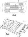
FIG. 1 is rear left perspective view of an automobile vehicle having a battery pack safety system for a battery powered vehicle according to an exemplary embodiment; -
FIG. 2 is a top left perspective view of a battery pack of the present disclosure; -
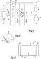
FIG. 3 is a cross sectional top plan view taken at section 3 ofFIG. 2 ; -
FIG. 4 is a top perspective view of area 4 ofFIG. 3 ; -
FIG. 5 is a cross sectional top plan view similar toFIG. 3 ; -
FIG. 6 is a top left perspective view of area 6 ofFIG. 5 ; -
FIG. 7 is a cross sectional front elevational view taken at section 7 ofFIG. 6 ; -
FIG. 8 is a cross sectional top plan view similar toFIG. 3 ; -
FIG. 9 is a top left perspective view ofarea 9 ofFIG. 8 ; -
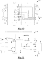
FIG. 10 is a cross sectional top plan view similar toFIG. 3 ; -
FIG. 11 is a diagrammatic presentation of the battery pack safety system for a battery powered vehicle according to an exemplary embodiment; -
FIG. 12 is a front perspective view of the vehicle ofFIG. 1 ; and -
FIG. 13 is a bottom perspective view ofarea 13 ofFIG. 2 . - The following description is merely exemplary in nature and is not intended to limit the present disclosure, application, or uses.
- Referring to
FIG. 1 , a vehicle batterysafety sensor system 10 is incorporated with with a battery unit orbattery pack 12 mounted to avehicle 14. Thebattery pack 12 provides an electrical charge as the sole power to propel thevehicle 14, or may provide supplemental power in addition to an engine (not shown). - Referring to
FIG. 2 and again toFIG. 1 , the vehicle batterysafety sensor system 10 together with thebattery pack 12 are supported using a structural unit orframe 16 made for example from one or more materials such as a metal including aluminum, or a combination of materials such as a metal and a polymeric material or a composite material. Theframe 16 may provide one ormore mounting flanges 18 to connect theframe 16 to structure of thevehicle 14. The vehicle batterysafety sensor system 10 further includes a strandedenergy discharge module 20 permitting battery cell discharge in the event of an accident, and a batteryemergency response module 22 which can provide signals locally or remotely for a vehicle and a battery emergency condition. The vehicle batterysafety sensor system 10 further includes asafety module 24 which will be described in greater detail below. - Referring to
FIG. 3 and again toFIG. 2 , thebattery pack 12 includes at least one and according to several aspectsmultiple battery cells 26. Each successive pair of thebattery cells 26 may be separated by a dividing barrier orcross beam 28. In further aspects, thebattery cells 26 are not separated by cross beams, but are positioned in an open cell space. According to several aspects, the vehicle batterysafety sensor system 10 provides at least one and according to several aspects multiple sensors connected to theframe 16 supporting thebattery pack 12, including at least one impact sensor connected to one of the walls of theframe 16, or may include multiple impact sensors each connected to one or more of the walls of theframe 16, such as afirst impact sensor 30, asecond impact sensor 32, athird impact sensor 34 and afourth impact sensor 36. According to several aspects, one impact sensor such as thefirst impact sensor 30 is mounted to one of the side walls. According to further aspects, one of the first, second, third, andfourth impact sensors battery pack 12, to provide sensed impact values for each side of thebattery pack 12. An output from the impact sensor or sensors, such as from each of the first, second, third, andfourth impact sensors safety module 24. Each of the impact sensors may be provided in the form of an accelerometer or a strain gage. - According to several aspects, the one or more impact sensors provide an output signal in response to a predefined structural loading applied to the
frame 16. For example, when multiple impact sensors are provided, an output signal from any single one of the impact sensors may indicate a localized impact and damage to the area of theframe 16 where that impact sensor is mounted. An output from the impact sensors can be cumulatively collected as well. For example, a first predefined cumulative level of strain or impact energy may trigger an impact sensor output signal indicating damage less than total may require repair to theframe 16. Similarly, a second predefined cumulative level of strain may trigger an impact sensor output signal indicating a failure of theframe 16 has occurred. - Referring to
FIG. 4 and again toFIG. 3 , each of the impact sensors such as the exemplaryfourth impact sensor 36 is mounted to an outer facingwall 38 of theframe 16. The impact sensors can also be positioned differently than shown and therefore about any desired position of theframe 16. - Referring to
FIG. 5 and again toFIG. 2 , theframe 16 of thebattery pack 12 may include a single large battery cell bay or may include multiple battery cell bays such as an exemplarybattery cell bay 38 which may be bounded between successive cross beams 28, such as between cross beams 28(1), 28(2). In order to collect any fluid leakage that may occur from the battery cells, and also to collect any moisture such a water that may enter thebattery pack 12, each of thebattery cell bays 38 can include alow point 40. Moisture or battery fluid entering thebattery cell bays 38 collects at eachlow point 40 and is sensed by amoisture sensor 42 such as a water or battery fluid sensor positioned at thelow point 40. When fluid is present and triggers an output signal, the output signal from each of themultiple moisture sensors 42 is communicated to thesafety module 24. If desired, a particularbattery cell bay 38 wherein one of themoisture sensors 42 triggers may be identified by the vehicle batterysafety sensor system 10 of the present disclosure. Flowdirection arrows 44 indicate a general flow direction of fluid toward themoisture sensors 42 from one side of theframe 16, and oppositely directedflow arrows 45 indicate a general flow direction of fluid toward themoisture sensors 42 from an opposite side of theframe 16. Although themoisture sensors 42 are depicted positioned substantially in a central location of each of thebattery cell bays 38, thelow points 40, and therefore the position of themoisture sensors 42 can be moved toward either side of theframe 16 from those shown. - Referring to
FIG. 6 and again toFIG. 5 , each of themoisture sensors 42 can be a singular sensor, or according to several aspects can be provided as adouble sensor 46 as shown. The use ofdouble sensors 46 provides redundancy and an increased accuracy in the sensed moisture level. - Referring to
FIG. 7 and again toFIGS. 5 and 6 , abottom wall 47 of theframe 16 can be curved or pitched downwardly from each of successive ones of the cross beams 28, such as between cross beams 28(1), 28(2) toward the centrally locatedlow point 40. Thelow point 40 can also be positioned to the left or to the right of thelow point 40 as shown inFIG. 7 as desired, as well as toward or away from the viewer. According to several aspects a singlelow point 40 can also be provided for theentire frame 16, with weepholes 49 allowing fluid flow though each of the cross beams 28 to allow all fluid to collect in the singlelow point 40, and with a common pitch of thebattery pack 12 such as at a one degree downward angle that aids in the flow of liquid to thelow point 40. - Referring to
FIGS. 8 and 9 , and again toFIGS. 2 and3 , the vehicle batterysafety sensor system 10 can further include one ormore smoke sensors 48. Thesmoke sensors 48 can detect heat or smoke, and can be mounted to aninside wall 50 of theframe 16, for example at opposing inside corners of theframe 16. The output signal from each of themultiple smoke sensors 48 is communicated to thesafety module 24. - Referring to
FIG. 10 and again toFIGS. 2 through 9 , in addition to the above noted one or more of the first, second, third, andfourth impact sensors moisture sensors 42, and thesmoke sensors 48, the vehicle batterysafety sensor system 10 can further include one or more of each of a combination fire andsmoke sensor 52, at least one batteryfluid leak sensor 54 and at least oneaccelerometer 56. The output signals from all of the sensors of thebattery pack 12 are communicated to thesafety module 24. - Referring to
FIG. 11 and again toFIGS. 1 through 10 , an exemplary diagram of the vehicle batterysafety sensor system 10 of the present disclosure includes thesafety module 24 in communication with all of the sensors. Thesafety module 24 may provide computational capability and therefore may include features such as a memory including anEEPROM 58. Thesafety module 24 receives the output signals from each of the multiple sensors such as the first, second, third, andfourth impact sensors moisture sensors 42, the batteryfluid leak sensors 54, and theaccelerometers 56 and coordinates an output signal indicating a condition of thebattery pack 12 and theframe 16. Thesafety module 24 is in communication with a vehicle main computer such as an electronic control unit (ECU) 60 via a highspeed CAN interface 62. Aconnector 64 is provided with thesafety system 10 providing power and communication terminals, including ahigh speed CAN 66 and alow speed CAN 68 for communication with theECU 60. A safetymodule power supply 70 is also connected via theconnector 64 to apositive power terminal 72 and aground terminal 74, thereby providing backup power for operation of thesafety module 24 if power from thebattery pack 12 is unavailable. - A
warning module 76 is also in communication with thevehicle ECU 60, such that when a signal is forwarded by thesafety module 24 to thevehicle ECU 60 thevehicle ECU 60 may energize any one or all of multiple different vehicle external warnings, including sounding of a vehicle horn or a separate sound emitting device in a pattern indicative of a condition of thebattery pack 12 such as a rapid on-off sounding of the horn, flashing of either or both of the vehicle headlights or rear tail-lights in a pattern indicative of a condition of thebattery pack 12 such as a predetermined on-off sequence, a remote signal sent via a wireless signal device, an internal message directed to the operator of thevehicle 10 such as a text message indicating the condition of the battery pack such as for example a smoke condition or structural damage to theframe 16, and the like can be initiated in the event of an output signal being transmitted from any one of the sensors of the vehicle batterysafety sensor system 10. Thewarning module 76 is in communication with thesafety module 24, such that thewarning module 26 when initiated by a signal from thesafety module 24 energizes a signaling device described in reference toFIG. 12 providing external vehicle indication of a status of thebattery pack 12. - Referring to
FIG. 12 and again toFIGS. 1 and11 , if thevehicle 14 is in an accident or damage occurs to theframe 16, the vehicle batterysafety sensor system 10 using thesafety module 24 forwards signals from the various sensors to thevehicle ECU 60, which determines based on a condition of thevehicle 14 whether to provide external visual indication of the vehicle condition to a first responder by energizing operation of a signaling device such as but not limited tovehicle lights 78 such as the headlights and taillights. A predetermined pattern of light operation such as for example by blinking three times can indicate smoke in thebattery pack 12 or a battery fire, or by blinking four times can indicate a battery leak. The signaling device can also define an external audible indication of the vehicle condition which can be provided by operation of a sound emitting device orvehicle horn 80. A first responder can also provide a strandedenergy discharge device 82 and anenergy discharge cable 84 which may be used to discharge the stored energy charge of thebattery pack 12. Signals from thesafety module 24 can be transmitted even in the event that the power supply from the 12VDC battery pack 12 is cut by a first responder in an emergency. - Referring to
FIG. 13 and again toFIGS. 3 and12 , because it must be assumed thebattery pack 12 holds a charge, the strandedenergy discharge module 20 of thebattery pack 12 includes apower discharge port 86 which can be connected to themultiple battery cells 26 of thebattery pack 12 via a passage created through theframe 16. Energy from themultiple battery cells 26 of thebattery pack 12 can be bled off to theenergy discharge device 82 via theenergy discharge cable 84 which is adapted to connect directly to thepower discharge port 86. - A vehicle battery
safety sensor system 10 including asafety module 24 of the present disclosure offers several advantages. These include the provision of multiple different types of sensors directly in or supported on theframe 16 of thebattery pack 12, each communicating with thesafety module 24 to centrally collect any sensor output signals. The sensors provide indication of the condition of thebattery pack 12 both to the vehicle operator such as to a center stack or to a speedometer gage cluster, and to parties passing thevehicle 14 and to a first responder if thevehicle 14 is in an accident or is stranded. Thesafety module 24 of the present disclosure provides a unified collector for all of the sensor output signals for subsequent communication with the vehicle ECU. - The description of the present disclosure is merely exemplary in nature and variations that do not depart from the gist of the present disclosure are intended to be within the scope of the present disclosure. Such variations are not to be regarded as a departure from the spirit and scope of the present disclosure.
Claims (15)
- A battery pack safety system (10) for a battery powered vehicle (14), comprising:a safety module (24) in communication with a vehicle battery pack (12) holding an electrical charge;at least one battery pack sensor in communication with the safety module (24); anda warning module (76) in communication with the safety module (24), the warning module (76), when initiated by a signal from the safety module (24) in response to an output signal from the at least one battery pack sensor, energizing a signaling device providing external vehicle indication of a status of the battery pack (12).
- The battery pack safety system (10) for a battery powered vehicle (14) of claim 1, wherein the battery pack (12) includes a frame (16) mounted to the vehicle (14), the at least one battery pack sensor supported by the frame (16).
- The battery pack safety system (10) for a battery powered vehicle (14) of claim 2, wherein the frame (16) includes a low point (40) for gravity collection of a fluid.
- The battery pack safety system (10) for a battery powered vehicle (14) of claim 3, wherein the at least one battery pack sensor defines at least one of a moisture sensor (42) and a battery fluid sensor located at the low point (40).
- The battery pack safety system (10) for a battery powered vehicle (14) of claims 1 or 2, wherein the at least one battery pack sensor defines an impact sensor and/or a smoke sensor (48) and/or at least one of a battery fluid sensor and a moisture sensor (42) and/or an accelerometer (56).
- The battery pack safety system (10) for a battery powered vehicle (14) of claims 1 or 2, wherein the at least one battery pack sensor includes at least one of a moisture sensor (42), an impact sensor (30, 32, 34, 36), and a smoke sensor (48), wherein an output from the safety module (24) is in communication with a vehicle electronics control unit (60) in direct communication with the warning module (76).
- The battery pack safety system (10) for a battery powered vehicle (14) of claim 2, wherein the frame (16) includes multiple bays each containing a battery cell (26), each of the bays having a low point (40) for gravity collection of a fluid; and the at least one battery pack sensor defines multiple moisture sensors (42) each located at the low point (40) of one of the multiple bays.
- The battery pack safety system (10) for a battery powered vehicle (14) of claim 1, wherein the at least one battery pack sensor includes
multiple battery pack sensors in communication with the safety module (24) and the output signal is generated by any of the multiple battery pack sensors; further comprising:
a safety module power supply (70) providing backup power for operation of the multiple battery pack sensors and the safety module (24) when the electrical charge of the battery pack (12) is unavailable. - The battery pack safety system (10) for a battery powered vehicle (14) of claim 8, wherein the battery pack (12) includes a frame (16) mounted to the vehicle (14), the frame (16) having multiple sides, the multiple battery pack sensors including impact sensors (30, 32, 34, 36) individually mounted to one or more of the multiple sides of the frame (16).
- The battery pack safety system (10) for a battery powered vehicle (14) of claim 9, wherein the battery pack (12) includes multiple bays each having a battery cell (26), and wherein the frame (16) includes a low point (40) with one of the multiple battery pack sensors defining a fluid sensor positioned at the low point (40).
- The battery pack safety system (10) for a battery powered vehicle (14) of any one of claims 8 to 10, wherein the warning module (76) is in communication with at least one of a headlight and a taillight of the vehicle (14) and the warning module (76) preferably operates the at least one of the headlight and the taillight of the vehicle (14) in an on-off pattern indicative of a condition of the battery pack (12).
- The battery pack safety system (10) for a battery powered vehicle (14) of any one of claims 8 to 11, wherein the warning module (76) is in communication with a sound generating device of the vehicle and the warning module (76) preferably operates the sound generating device in a pattern indicative of a condition of the battery pack (12).
- The battery pack safety system (10) for a battery powered vehicle (14) of claim 8, wherein
the vehicle battery pack (12) has at least one battery cell (26) positioned in a bay of a frame (16); the multiple battery pack sensors are each connected to the frame (16) and
the safety module (24) is in communication with each of the multiple battery pack sensors to collect an output of each of the battery pack sensors for transmission to a vehicle central computer unit (60). - The battery pack safety system (10) for a battery powered vehicle (14) of claim 13, wherein the at least one battery cell (26) defines multiple battery cells (26) each independently positioned in a bay of the frame (16).
- The battery pack safety system (10) for a battery powered vehicle (14) of claims 13 or 14, wherein the multiple battery pack sensors include at least one of each of a moisture sensor (42) or a battery fluid sensor determining a level of a fluid in the battery pack (12), an impact sensor (30, 32, 36, 36) determining a strain loading applied to the frame (16), and a smoke sensor (48) determining if smoke is present within the battery pack (12).
Applications Claiming Priority (1)
| Application Number | Priority Date | Filing Date | Title |
|---|---|---|---|
| US15/626,692 US10777856B2 (en) | 2017-06-19 | 2017-06-19 | Safety sensor module with vehicle communication to first responders |
Publications (2)
| Publication Number | Publication Date |
|---|---|
| EP3418102A1 true EP3418102A1 (en) | 2018-12-26 |
| EP3418102B1 EP3418102B1 (en) | 2021-08-11 |
Family
ID=62200354
Family Applications (1)
| Application Number | Title | Priority Date | Filing Date |
|---|---|---|---|
| EP18173088.8A Active EP3418102B1 (en) | 2017-06-19 | 2018-05-18 | Vehicle safety sensor module with communication to first responders |
Country Status (3)
| Country | Link |
|---|---|
| US (1) | US10777856B2 (en) |
| EP (1) | EP3418102B1 (en) |
| CN (1) | CN109228837B (en) |
Cited By (2)
| Publication number | Priority date | Publication date | Assignee | Title |
|---|---|---|---|---|
| EP3476645A1 (en) * | 2017-10-31 | 2019-05-01 | Dura Operating, LLC | Liquid detection inside a battery tray to avoid battery malfunction |
| EP4357197A1 (en) * | 2022-10-17 | 2024-04-24 | Volvo Truck Corporation | Warning system for an energy storage system and method for controlling the warning system |
Families Citing this family (14)
| Publication number | Priority date | Publication date | Assignee | Title |
|---|---|---|---|---|
| US11099925B2 (en) | 2018-07-10 | 2021-08-24 | EMC IP Holding Company LLC | Datacenter preemptive measures for improving protection using IoT sensors |
| US11106528B2 (en) * | 2018-10-10 | 2021-08-31 | EMC IP Holding Company LLC | Datacenter IoT-triggered preemptive measures using machine learning |
| DE102018129158B4 (en) * | 2018-11-20 | 2021-05-06 | Dr. Ing. H.C. F. Porsche Aktiengesellschaft | Safety device for a battery |
| JP7390916B2 (en) * | 2020-02-10 | 2023-12-04 | 株式会社Subaru | Battery status notification device for electric vehicles |
| KR102726812B1 (en) * | 2020-03-11 | 2024-11-05 | 현대자동차주식회사 | Battery release system for vehicle |
| KR102726809B1 (en) * | 2020-03-11 | 2024-11-06 | 현대자동차주식회사 | Battery release system for vehicle |
| DE102020120627B3 (en) * | 2020-08-05 | 2021-12-02 | Dr. Ing. H.C. F. Porsche Aktiengesellschaft | Battery case for a motor vehicle battery |
| CN112026523B (en) * | 2020-08-31 | 2022-01-18 | 蜂巢能源科技有限公司 | Battery pack sealing performance detection system and electric vehicle |
| US11721988B2 (en) * | 2020-11-13 | 2023-08-08 | Dana Automotive Systems Group, Llc | Methods and systems for an emergency response unit |
| CN214689046U (en) | 2020-12-23 | 2021-11-12 | 比亚迪股份有限公司 | Battery package protection system and vehicle |
| US20220200070A1 (en) * | 2020-12-23 | 2022-06-23 | Brunswick Corporation | Marine battery with water ingress and shock detection |
| US12113225B2 (en) * | 2021-04-09 | 2024-10-08 | Brunswick Corporation | Watertight marine battery |
| US12230774B2 (en) * | 2021-04-09 | 2025-02-18 | Brunswick Corporation | Marine battery safety system and method |
| CN114740009A (en) * | 2022-04-02 | 2022-07-12 | 奇瑞汽车股份有限公司 | Battery shell bottom plate damage detection method and device and storage medium |
Citations (2)
| Publication number | Priority date | Publication date | Assignee | Title |
|---|---|---|---|---|
| US20120150393A1 (en) * | 2009-09-04 | 2012-06-14 | Autoliv Development Ab | vehicle battery safety system |
| WO2016077117A1 (en) * | 2014-11-14 | 2016-05-19 | Johnson Controls Technology Company | Liquid trap for a lithium ion battery system |
Family Cites Families (20)
| Publication number | Priority date | Publication date | Assignee | Title |
|---|---|---|---|---|
| US4798968A (en) | 1987-05-15 | 1989-01-17 | Deem James R | Battery disconnect apparatus |
| US5034620A (en) | 1989-12-13 | 1991-07-23 | Cameron Robert W | Vehicle battery safety switch |
| JPH11219732A (en) | 1998-02-03 | 1999-08-10 | Toyo System Kk | Battery charge / discharge device |
| FR2810796B1 (en) | 2000-06-26 | 2003-03-21 | Cit Alcatel | ELECTROCHEMICAL GENERATOR BATTERY COMPRISING A SAFETY DEVICE |
| US7339774B2 (en) | 2000-11-03 | 2008-03-04 | Zdziech Peter M | Automatic battery disconnect system |
| JP2002289262A (en) | 2001-03-23 | 2002-10-04 | Mitsubishi Heavy Ind Ltd | Lithium secondary battery monitoring system |
| KR100889244B1 (en) | 2005-04-20 | 2009-03-17 | 주식회사 엘지화학 | Secondary Battery Module with Piezoelectric Sensor |
| WO2006118386A1 (en) | 2005-05-02 | 2006-11-09 | Lg Chem, Ltd. | Improved middle or large-sized battery pack of increased safety |
| KR100853618B1 (en) | 2006-01-04 | 2008-08-25 | 주식회사 엘지화학 | Medium and large battery packs with safety devices |
| US7521817B2 (en) | 2006-05-03 | 2009-04-21 | Donald Gors | System and method for reducing the chance of fires and/or explosions |
| US7433794B1 (en) | 2007-07-18 | 2008-10-07 | Tesla Motors, Inc. | Mitigation of propagation of thermal runaway in a multi-cell battery pack |
| JP4786700B2 (en) | 2008-12-24 | 2011-10-05 | 三菱重工業株式会社 | Battery module |
| EP2216849B1 (en) | 2009-02-10 | 2011-10-05 | Autoliv Development AB | A safety arrangement for a motor vehicle |
| US8307934B2 (en) | 2009-06-23 | 2012-11-13 | GTR Development LLC | Vehicle fire prevention and detection system |
| US8846232B2 (en) | 2009-11-11 | 2014-09-30 | Atieva, Inc. | Flash cooling system for increased battery safety |
| CN104054230A (en) | 2011-11-07 | 2014-09-17 | 台湾立凯绿能移动股份有限公司 | Battery module anomaly detection system and detection method thereof |
| CN103208598B (en) * | 2012-01-16 | 2016-06-29 | 微宏动力系统(湖州)有限公司 | Set of cells and method for detecting leakage thereof |
| DE102012222070B4 (en) | 2012-12-03 | 2024-08-14 | Robert Bosch Gmbh | Warning system for monitoring a vehicle battery |
| DE102014202416A1 (en) | 2014-02-11 | 2015-08-13 | Robert Bosch Gmbh | Safety device for a contactor |
| DE102014206821A1 (en) * | 2014-04-09 | 2015-10-15 | Robert Bosch Gmbh | Device and method for testing a battery component and battery, battery system and vehicle |
-
2017
- 2017-06-19 US US15/626,692 patent/US10777856B2/en active Active
-
2018
- 2018-05-16 CN CN201810469737.6A patent/CN109228837B/en active Active
- 2018-05-18 EP EP18173088.8A patent/EP3418102B1/en active Active
Patent Citations (2)
| Publication number | Priority date | Publication date | Assignee | Title |
|---|---|---|---|---|
| US20120150393A1 (en) * | 2009-09-04 | 2012-06-14 | Autoliv Development Ab | vehicle battery safety system |
| WO2016077117A1 (en) * | 2014-11-14 | 2016-05-19 | Johnson Controls Technology Company | Liquid trap for a lithium ion battery system |
Cited By (3)
| Publication number | Priority date | Publication date | Assignee | Title |
|---|---|---|---|---|
| EP3476645A1 (en) * | 2017-10-31 | 2019-05-01 | Dura Operating, LLC | Liquid detection inside a battery tray to avoid battery malfunction |
| US11114706B2 (en) | 2017-10-31 | 2021-09-07 | DUS Operating, LLC | Liquid detection inside a battery tray to avoid battery malfunction |
| EP4357197A1 (en) * | 2022-10-17 | 2024-04-24 | Volvo Truck Corporation | Warning system for an energy storage system and method for controlling the warning system |
Also Published As
| Publication number | Publication date |
|---|---|
| CN109228837B (en) | 2022-01-25 |
| US10777856B2 (en) | 2020-09-15 |
| CN109228837A (en) | 2019-01-18 |
| US20180366792A1 (en) | 2018-12-20 |
| EP3418102B1 (en) | 2021-08-11 |
Similar Documents
| Publication | Publication Date | Title |
|---|---|---|
| EP3418102B1 (en) | Vehicle safety sensor module with communication to first responders | |
| EP3418103B1 (en) | Vehicle safety sensor module with communication to first responders | |
| US10707538B2 (en) | Safety sensor module with vehicle communication to first responders | |
| EP3476645B1 (en) | Liquid detection inside a battery tray to avoid battery malfunction | |
| JP2006182300A (en) | Vehicle collision safety system | |
| JP7370388B2 (en) | Quick change connectors for electrical connector systems and electric vehicle battery packs | |
| CN112440897A (en) | Method for determining potential damage to a vehicle battery and motor vehicle having a vehicle battery | |
| CN106356579A (en) | Safety type power battery system for electric automobile | |
| JP6686054B2 (en) | Vehicle control system | |
| CN108986399A (en) | A kind of vehicle-mounted accident automatic alarm early warning system | |
| CN204557596U (en) | A kind of automobile black box and acquisition system | |
| EP4292860A1 (en) | Methods, an external battery monitoring module and an external battery monitoring system for obtaining one or more battery parameter values and/or for indicating if a critical condition is present for at least one propulsion battery | |
| KR20220028251A (en) | Construction equipment and its driving method | |
| CN214542329U (en) | Liquid cooling power battery detection device that leaks | |
| CN214564964U (en) | Hydrogen vehicle pedestrian PD detection system | |
| CN206418425U (en) | A kind of intelligentized plant area's limit for height pre-warning management system | |
| CN118343240A (en) | Motorcycle | |
| CN206287823U (en) | A kind of shock processing unit of electric automobile | |
| CN202294496U (en) | Lateral detection device for vehicle | |
| CN116923245B (en) | Early warning device for vehicle and vehicle | |
| CN215042638U (en) | Automobile rescue assisting device | |
| CN206812883U (en) | A kind of anti-vehicular communication unit to knock into the back | |
| JPS6354700A (en) | Abnormal access alarm | |
| CN113566879A (en) | Dangerous article road transportation danger early warning detection device and system | |
| CN118348520A (en) | Motorcycle |
Legal Events
| Date | Code | Title | Description |
|---|---|---|---|
| PUAI | Public reference made under article 153(3) epc to a published international application that has entered the european phase |
Free format text: ORIGINAL CODE: 0009012 |
|
| STAA | Information on the status of an ep patent application or granted ep patent |
Free format text: STATUS: THE APPLICATION HAS BEEN PUBLISHED |
|
| AK | Designated contracting states |
Kind code of ref document: A1 Designated state(s): AL AT BE BG CH CY CZ DE DK EE ES FI FR GB GR HR HU IE IS IT LI LT LU LV MC MK MT NL NO PL PT RO RS SE SI SK SM TR |
|
| AX | Request for extension of the european patent |
Extension state: BA ME |
|
| STAA | Information on the status of an ep patent application or granted ep patent |
Free format text: STATUS: REQUEST FOR EXAMINATION WAS MADE |
|
| STAA | Information on the status of an ep patent application or granted ep patent |
Free format text: STATUS: EXAMINATION IS IN PROGRESS |
|
| 17P | Request for examination filed |
Effective date: 20190626 |
|
| RBV | Designated contracting states (corrected) |
Designated state(s): AL AT BE BG CH CY CZ DE DK EE ES FI FR GB GR HR HU IE IS IT LI LT LU LV MC MK MT NL NO PL PT RO RS SE SI SK SM TR |
|
| 17Q | First examination report despatched |
Effective date: 20190730 |
|
| RIC1 | Information provided on ipc code assigned before grant |
Ipc: H01M 2/00 20060101AFI20200214BHEP Ipc: B60L 3/00 20190101ALI20200214BHEP |
|
| GRAP | Despatch of communication of intention to grant a patent |
Free format text: ORIGINAL CODE: EPIDOSNIGR1 |
|
| STAA | Information on the status of an ep patent application or granted ep patent |
Free format text: STATUS: GRANT OF PATENT IS INTENDED |
|
| RIC1 | Information provided on ipc code assigned before grant |
Ipc: B60L 3/00 20190101AFI20210127BHEP |
|
| INTG | Intention to grant announced |
Effective date: 20210219 |
|
| RAP1 | Party data changed (applicant data changed or rights of an application transferred) |
Owner name: DUS OPERATING, INC. |
|
| GRAS | Grant fee paid |
Free format text: ORIGINAL CODE: EPIDOSNIGR3 |
|
| GRAA | (expected) grant |
Free format text: ORIGINAL CODE: 0009210 |
|
| STAA | Information on the status of an ep patent application or granted ep patent |
Free format text: STATUS: THE PATENT HAS BEEN GRANTED |
|
| AK | Designated contracting states |
Kind code of ref document: B1 Designated state(s): AL AT BE BG CH CY CZ DE DK EE ES FI FR GB GR HR HU IE IS IT LI LT LU LV MC MK MT NL NO PL PT RO RS SE SI SK SM TR |
|
| REG | Reference to a national code |
Ref country code: CH Ref legal event code: EP |
|
| REG | Reference to a national code |
Ref country code: DE Ref legal event code: R096 Ref document number: 602018021484 Country of ref document: DE |
|
| REG | Reference to a national code |
Ref country code: IE Ref legal event code: FG4D Ref country code: AT Ref legal event code: REF Ref document number: 1419054 Country of ref document: AT Kind code of ref document: T Effective date: 20210915 |
|
| REG | Reference to a national code |
Ref country code: LT Ref legal event code: MG9D |
|
| REG | Reference to a national code |
Ref country code: NL Ref legal event code: MP Effective date: 20210811 |
|
| REG | Reference to a national code |
Ref country code: AT Ref legal event code: MK05 Ref document number: 1419054 Country of ref document: AT Kind code of ref document: T Effective date: 20210811 |
|
| PG25 | Lapsed in a contracting state [announced via postgrant information from national office to epo] |
Ref country code: SE Free format text: LAPSE BECAUSE OF FAILURE TO SUBMIT A TRANSLATION OF THE DESCRIPTION OR TO PAY THE FEE WITHIN THE PRESCRIBED TIME-LIMIT Effective date: 20210811 Ref country code: RS Free format text: LAPSE BECAUSE OF FAILURE TO SUBMIT A TRANSLATION OF THE DESCRIPTION OR TO PAY THE FEE WITHIN THE PRESCRIBED TIME-LIMIT Effective date: 20210811 Ref country code: HR Free format text: LAPSE BECAUSE OF FAILURE TO SUBMIT A TRANSLATION OF THE DESCRIPTION OR TO PAY THE FEE WITHIN THE PRESCRIBED TIME-LIMIT Effective date: 20210811 Ref country code: ES Free format text: LAPSE BECAUSE OF FAILURE TO SUBMIT A TRANSLATION OF THE DESCRIPTION OR TO PAY THE FEE WITHIN THE PRESCRIBED TIME-LIMIT Effective date: 20210811 Ref country code: FI Free format text: LAPSE BECAUSE OF FAILURE TO SUBMIT A TRANSLATION OF THE DESCRIPTION OR TO PAY THE FEE WITHIN THE PRESCRIBED TIME-LIMIT Effective date: 20210811 Ref country code: PT Free format text: LAPSE BECAUSE OF FAILURE TO SUBMIT A TRANSLATION OF THE DESCRIPTION OR TO PAY THE FEE WITHIN THE PRESCRIBED TIME-LIMIT Effective date: 20211213 Ref country code: NO Free format text: LAPSE BECAUSE OF FAILURE TO SUBMIT A TRANSLATION OF THE DESCRIPTION OR TO PAY THE FEE WITHIN THE PRESCRIBED TIME-LIMIT Effective date: 20211111 Ref country code: LT Free format text: LAPSE BECAUSE OF FAILURE TO SUBMIT A TRANSLATION OF THE DESCRIPTION OR TO PAY THE FEE WITHIN THE PRESCRIBED TIME-LIMIT Effective date: 20210811 Ref country code: BG Free format text: LAPSE BECAUSE OF FAILURE TO SUBMIT A TRANSLATION OF THE DESCRIPTION OR TO PAY THE FEE WITHIN THE PRESCRIBED TIME-LIMIT Effective date: 20211111 Ref country code: AT Free format text: LAPSE BECAUSE OF FAILURE TO SUBMIT A TRANSLATION OF THE DESCRIPTION OR TO PAY THE FEE WITHIN THE PRESCRIBED TIME-LIMIT Effective date: 20210811 |
|
| PG25 | Lapsed in a contracting state [announced via postgrant information from national office to epo] |
Ref country code: PL Free format text: LAPSE BECAUSE OF FAILURE TO SUBMIT A TRANSLATION OF THE DESCRIPTION OR TO PAY THE FEE WITHIN THE PRESCRIBED TIME-LIMIT Effective date: 20210811 Ref country code: LV Free format text: LAPSE BECAUSE OF FAILURE TO SUBMIT A TRANSLATION OF THE DESCRIPTION OR TO PAY THE FEE WITHIN THE PRESCRIBED TIME-LIMIT Effective date: 20210811 Ref country code: GR Free format text: LAPSE BECAUSE OF FAILURE TO SUBMIT A TRANSLATION OF THE DESCRIPTION OR TO PAY THE FEE WITHIN THE PRESCRIBED TIME-LIMIT Effective date: 20211112 |
|
| PG25 | Lapsed in a contracting state [announced via postgrant information from national office to epo] |
Ref country code: NL Free format text: LAPSE BECAUSE OF FAILURE TO SUBMIT A TRANSLATION OF THE DESCRIPTION OR TO PAY THE FEE WITHIN THE PRESCRIBED TIME-LIMIT Effective date: 20210811 |
|
| PG25 | Lapsed in a contracting state [announced via postgrant information from national office to epo] |
Ref country code: DK Free format text: LAPSE BECAUSE OF FAILURE TO SUBMIT A TRANSLATION OF THE DESCRIPTION OR TO PAY THE FEE WITHIN THE PRESCRIBED TIME-LIMIT Effective date: 20210811 |
|
| REG | Reference to a national code |
Ref country code: DE Ref legal event code: R097 Ref document number: 602018021484 Country of ref document: DE |
|
| PG25 | Lapsed in a contracting state [announced via postgrant information from national office to epo] |
Ref country code: SM Free format text: LAPSE BECAUSE OF FAILURE TO SUBMIT A TRANSLATION OF THE DESCRIPTION OR TO PAY THE FEE WITHIN THE PRESCRIBED TIME-LIMIT Effective date: 20210811 Ref country code: SK Free format text: LAPSE BECAUSE OF FAILURE TO SUBMIT A TRANSLATION OF THE DESCRIPTION OR TO PAY THE FEE WITHIN THE PRESCRIBED TIME-LIMIT Effective date: 20210811 Ref country code: RO Free format text: LAPSE BECAUSE OF FAILURE TO SUBMIT A TRANSLATION OF THE DESCRIPTION OR TO PAY THE FEE WITHIN THE PRESCRIBED TIME-LIMIT Effective date: 20210811 Ref country code: EE Free format text: LAPSE BECAUSE OF FAILURE TO SUBMIT A TRANSLATION OF THE DESCRIPTION OR TO PAY THE FEE WITHIN THE PRESCRIBED TIME-LIMIT Effective date: 20210811 Ref country code: CZ Free format text: LAPSE BECAUSE OF FAILURE TO SUBMIT A TRANSLATION OF THE DESCRIPTION OR TO PAY THE FEE WITHIN THE PRESCRIBED TIME-LIMIT Effective date: 20210811 Ref country code: AL Free format text: LAPSE BECAUSE OF FAILURE TO SUBMIT A TRANSLATION OF THE DESCRIPTION OR TO PAY THE FEE WITHIN THE PRESCRIBED TIME-LIMIT Effective date: 20210811 |
|
| PLBE | No opposition filed within time limit |
Free format text: ORIGINAL CODE: 0009261 |
|
| STAA | Information on the status of an ep patent application or granted ep patent |
Free format text: STATUS: NO OPPOSITION FILED WITHIN TIME LIMIT |
|
| 26N | No opposition filed |
Effective date: 20220512 |
|
| PG25 | Lapsed in a contracting state [announced via postgrant information from national office to epo] |
Ref country code: IT Free format text: LAPSE BECAUSE OF FAILURE TO SUBMIT A TRANSLATION OF THE DESCRIPTION OR TO PAY THE FEE WITHIN THE PRESCRIBED TIME-LIMIT Effective date: 20210811 |
|
| PG25 | Lapsed in a contracting state [announced via postgrant information from national office to epo] |
Ref country code: SI Free format text: LAPSE BECAUSE OF FAILURE TO SUBMIT A TRANSLATION OF THE DESCRIPTION OR TO PAY THE FEE WITHIN THE PRESCRIBED TIME-LIMIT Effective date: 20210811 |
|
| REG | Reference to a national code |
Ref country code: CH Ref legal event code: PL |
|
| REG | Reference to a national code |
Ref country code: BE Ref legal event code: MM Effective date: 20220531 |
|
| PG25 | Lapsed in a contracting state [announced via postgrant information from national office to epo] |
Ref country code: MC Free format text: LAPSE BECAUSE OF FAILURE TO SUBMIT A TRANSLATION OF THE DESCRIPTION OR TO PAY THE FEE WITHIN THE PRESCRIBED TIME-LIMIT Effective date: 20210811 Ref country code: LI Free format text: LAPSE BECAUSE OF NON-PAYMENT OF DUE FEES Effective date: 20220531 Ref country code: CH Free format text: LAPSE BECAUSE OF NON-PAYMENT OF DUE FEES Effective date: 20220531 Ref country code: LU Free format text: LAPSE BECAUSE OF NON-PAYMENT OF DUE FEES Effective date: 20220518 |
|
| PG25 | Lapsed in a contracting state [announced via postgrant information from national office to epo] |
Ref country code: IE Free format text: LAPSE BECAUSE OF NON-PAYMENT OF DUE FEES Effective date: 20220518 |
|
| PG25 | Lapsed in a contracting state [announced via postgrant information from national office to epo] |
Ref country code: BE Free format text: LAPSE BECAUSE OF NON-PAYMENT OF DUE FEES Effective date: 20220531 |
|
| PG25 | Lapsed in a contracting state [announced via postgrant information from national office to epo] |
Ref country code: HU Free format text: LAPSE BECAUSE OF FAILURE TO SUBMIT A TRANSLATION OF THE DESCRIPTION OR TO PAY THE FEE WITHIN THE PRESCRIBED TIME-LIMIT; INVALID AB INITIO Effective date: 20180518 |
|
| PG25 | Lapsed in a contracting state [announced via postgrant information from national office to epo] |
Ref country code: MK Free format text: LAPSE BECAUSE OF FAILURE TO SUBMIT A TRANSLATION OF THE DESCRIPTION OR TO PAY THE FEE WITHIN THE PRESCRIBED TIME-LIMIT Effective date: 20210811 Ref country code: CY Free format text: LAPSE BECAUSE OF FAILURE TO SUBMIT A TRANSLATION OF THE DESCRIPTION OR TO PAY THE FEE WITHIN THE PRESCRIBED TIME-LIMIT Effective date: 20210811 |
|
| PGFP | Annual fee paid to national office [announced via postgrant information from national office to epo] |
Ref country code: GB Payment date: 20240522 Year of fee payment: 7 |
|
| PG25 | Lapsed in a contracting state [announced via postgrant information from national office to epo] |
Ref country code: MT Free format text: LAPSE BECAUSE OF FAILURE TO SUBMIT A TRANSLATION OF THE DESCRIPTION OR TO PAY THE FEE WITHIN THE PRESCRIBED TIME-LIMIT Effective date: 20210811 |
|
| REG | Reference to a national code |
Ref country code: DE Ref legal event code: R082 Ref document number: 602018021484 Country of ref document: DE Representative=s name: KBN IP PATENTANWAELTE PARTNERSCHAFT MBB, DE |
|
| PGFP | Annual fee paid to national office [announced via postgrant information from national office to epo] |
Ref country code: DE Payment date: 20250516 Year of fee payment: 8 |
|
| PGFP | Annual fee paid to national office [announced via postgrant information from national office to epo] |
Ref country code: FR Payment date: 20250523 Year of fee payment: 8 |
|
| PG25 | Lapsed in a contracting state [announced via postgrant information from national office to epo] |
Ref country code: TR Free format text: LAPSE BECAUSE OF FAILURE TO SUBMIT A TRANSLATION OF THE DESCRIPTION OR TO PAY THE FEE WITHIN THE PRESCRIBED TIME-LIMIT Effective date: 20210811 |
|
| GBPC | Gb: european patent ceased through non-payment of renewal fee |
Effective date: 20250518 |
|
| PG25 | Lapsed in a contracting state [announced via postgrant information from national office to epo] |
Ref country code: GB Free format text: LAPSE BECAUSE OF NON-PAYMENT OF DUE FEES Effective date: 20250518 |