EP3418098A1 - Drive axle assembly and engineering vehicle - Google Patents
Drive axle assembly and engineering vehicle Download PDFInfo
- Publication number
- EP3418098A1 EP3418098A1 EP16893887.6A EP16893887A EP3418098A1 EP 3418098 A1 EP3418098 A1 EP 3418098A1 EP 16893887 A EP16893887 A EP 16893887A EP 3418098 A1 EP3418098 A1 EP 3418098A1
- Authority
- EP
- European Patent Office
- Prior art keywords
- transfer case
- axle assembly
- drive axle
- construction vehicle
- main reducer
- Prior art date
- Legal status (The legal status is an assumption and is not a legal conclusion. Google has not performed a legal analysis and makes no representation as to the accuracy of the status listed.)
- Pending
Links
Images

Classifications
-
- B—PERFORMING OPERATIONS; TRANSPORTING
- B60—VEHICLES IN GENERAL
- B60K—ARRANGEMENT OR MOUNTING OF PROPULSION UNITS OR OF TRANSMISSIONS IN VEHICLES; ARRANGEMENT OR MOUNTING OF PLURAL DIVERSE PRIME-MOVERS IN VEHICLES; AUXILIARY DRIVES FOR VEHICLES; INSTRUMENTATION OR DASHBOARDS FOR VEHICLES; ARRANGEMENTS IN CONNECTION WITH COOLING, AIR INTAKE, GAS EXHAUST OR FUEL SUPPLY OF PROPULSION UNITS IN VEHICLES
- B60K17/00—Arrangement or mounting of transmissions in vehicles
- B60K17/04—Arrangement or mounting of transmissions in vehicles characterised by arrangement, location or kind of gearing
-
- B—PERFORMING OPERATIONS; TRANSPORTING
- B60—VEHICLES IN GENERAL
- B60K—ARRANGEMENT OR MOUNTING OF PROPULSION UNITS OR OF TRANSMISSIONS IN VEHICLES; ARRANGEMENT OR MOUNTING OF PLURAL DIVERSE PRIME-MOVERS IN VEHICLES; AUXILIARY DRIVES FOR VEHICLES; INSTRUMENTATION OR DASHBOARDS FOR VEHICLES; ARRANGEMENTS IN CONNECTION WITH COOLING, AIR INTAKE, GAS EXHAUST OR FUEL SUPPLY OF PROPULSION UNITS IN VEHICLES
- B60K17/00—Arrangement or mounting of transmissions in vehicles
- B60K17/34—Arrangement or mounting of transmissions in vehicles for driving both front and rear wheels, e.g. four wheel drive vehicles
- B60K17/344—Arrangement or mounting of transmissions in vehicles for driving both front and rear wheels, e.g. four wheel drive vehicles having a transfer gear
-
- B—PERFORMING OPERATIONS; TRANSPORTING
- B60—VEHICLES IN GENERAL
- B60K—ARRANGEMENT OR MOUNTING OF PROPULSION UNITS OR OF TRANSMISSIONS IN VEHICLES; ARRANGEMENT OR MOUNTING OF PLURAL DIVERSE PRIME-MOVERS IN VEHICLES; AUXILIARY DRIVES FOR VEHICLES; INSTRUMENTATION OR DASHBOARDS FOR VEHICLES; ARRANGEMENTS IN CONNECTION WITH COOLING, AIR INTAKE, GAS EXHAUST OR FUEL SUPPLY OF PROPULSION UNITS IN VEHICLES
- B60K17/00—Arrangement or mounting of transmissions in vehicles
- B60K17/34—Arrangement or mounting of transmissions in vehicles for driving both front and rear wheels, e.g. four wheel drive vehicles
- B60K17/344—Arrangement or mounting of transmissions in vehicles for driving both front and rear wheels, e.g. four wheel drive vehicles having a transfer gear
- B60K17/346—Arrangement or mounting of transmissions in vehicles for driving both front and rear wheels, e.g. four wheel drive vehicles having a transfer gear the transfer gear being a differential gear
-
- B—PERFORMING OPERATIONS; TRANSPORTING
- B60—VEHICLES IN GENERAL
- B60Y—INDEXING SCHEME RELATING TO ASPECTS CROSS-CUTTING VEHICLE TECHNOLOGY
- B60Y2200/00—Type of vehicle
- B60Y2200/40—Special vehicles
- B60Y2200/41—Construction vehicles, e.g. graders, excavators
Definitions
- the present disclosure relates to the technical field of construction vehicles.
- the present disclosure relates to a drive axle assembly and a construction vehicle.
- An integral axle means that the axle is an integral structure, with the wheels at two ends being linked and not movable independent of each other, and a drive axle based on the integral axle has its main reducer housing rigidly connected with an axle housing to form an integral beam.
- a disconnected axle means that the middle of the axle is hinged, with the wheels at two ends being movable independent of each other, and a drive axle based on the disconnected axle has its main reducer fixedly connected to a frame.
- the disconnected axle is for use in family cars, while in the existing construction vehicles such as cranes and the like, the integral axle structure is employed, and a transfer case and a main reducer are connected via a transmission shaft.
- a construction vehicle with four axles or below requires compact structural arrangement.
- a transmission is connected to the transfer case through a transmission shaft, and after reducing distance and distributing torque, the transfer case is connected to a front drive axle and a rear drive axle through the transmission shaft.
- the transfer case of the three-axle all terrain crane is disposed between the first axle and the second axle and is closer to the first axle.
- the transfer case is connected to the first axle and the second axle through the transmission shaft.
- a solution to this problem is designing the first axle as non-drive axle, which means that the construction vehicle can only accomplish the second-axle and third-axle drive, and is unable to accomplish the first- axle and third-axle drive or full-axle drive.
- the performance of the whole vehicle may be restricted when the first axle is designed as non-drive axle.
- An object of the present disclosure is to provide a drive axle assembly and a construction vehicle, which not only can save the arrangement space and accomplish more driving schemes, but also has smaller unsprung mass to impart less impact on the frame.
- the present disclosure provides a drive axle assembly for a construction vehicle.
- the drive axle assembly comprises a left wheel, aright wheel, a disconnected axle, a main reducer, and a transfer case.
- the main reducer is drivingly connected with the left wheel and the right wheel through the disconnected axle.
- the main reducer is drivingly connected with the transfer case, and has a housing connected with a housing of the transfer case.
- the main reducer is fixedly connected with a frame of the construction vehicle.
- the transfer case is provided with an auxiliary support for connection with the frame.
- a front end surface of the transfer case is provided with a forward output flange for being drivingly connected with a front axle assembly of the construction vehicle
- a rear end surface of the main reducer is provided with a rearward output flange for being drivingly connected with a rear axle assembly of the construction vehicle.
- the transfer case is configured to transmit power to the forward output flange through a forward output shaft, and an eddy current retarder, which has a fixed portion and a rotation portion rotatably provided with respect to the fixed portion, is provided on the forward output flange. Either of the fixed portion and the rotation portion is arranged on the forward output shaft of the transfer case, and the other one is arranged on the forward output flange.
- the transfer case is provided with at least one power take-off port for connection with an auxiliary power device.
- the auxiliary power device comprises an oil pump and a steering emergency pump
- the at least one power take-off port comprises a first power take-off port for connection with the oil pump and a second power take-off port for connection with the steering emergency pump.
- the transfer case has an input flange for connection with a transmission of the construction vehicle, and an output flange for connection with other drive axles of the construction vehicle, the input flange being located above the output flange.
- the drive axle assembly further comprises two suspension cylinders and two swing rods, wherein the two suspension cylinders are arranged between a wheel-side assembly of the left wheel and the frame and between a wheel-side assembly of the right wheel and the frame respectively, and the two swing rods are arranged correspondingly with the left and right wheels respectively, and an end of one side of each of the swing rods is hinged with the corresponding-side wheel via a ball hinge, and ends of the other side of each of the swing rods (16) are hinged with the main reducer via two ball hinges arranged in a front-and-rear direction.
- the swing rod is a V-shaped swing rod, of which the separated ends are hinged to a lower end surface of the main reducer.
- the present disclosure also provides a construction vehicle comprising a frame and the drive axle assembly of the present disclosure.
- the construction vehicle is a construction vehicle with four axles or below, with the drive axle assembly being disposed between a front axle assembly and a rear axle assembly of the construction vehicle.
- the present disclosure integrates the transfer case and the main reducer as an integral structure based on the disconnected axle, which not only can omit the transmission shaft between the transfer case and the main reducer as used in the prior art, save the layout space, reduce the weight of the drive axle assembly and facilitate the implementation of more driving schemes, but also enables the transfer case, integrated with the main reducer as an integral structure, to bounce independently of the wheels since the main reducer is fixedly connected with the frame. That is, the main reducer and the transfer case both belong to sprung mass, so that the drive axle assembly has a smaller unsprung mass, capable of reducing the impact on the whole vehicle and improving the manipulating stability of the whole vehicle.
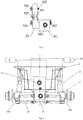
- Figs. 1-3 show a schematic structural view of a drive axle assembly according to an embodiment of the present disclosure
- Fig. 4 shows a schematic assembly view of the drive axle assembly according to another embodiment of the present disclosure and a frame
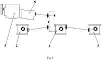
- Fig. 5 shows a schematic structural view of a construction vehicle according to an embodiment of the disclosure.
- a drive axle assembly 1 for a construction vehicle provided by the present disclosure comprises a left wheel 141, a right wheel 142, a disconnected axle, a main reducer 11, and a transfer case 12, wherein the main reducer 11 is drivingly connected with the left wheel 141 and the right wheel 142 through the disconnected axle, the main reducer 11 is drivingly connected with the transfer case 12, and a housing of the main reducer 11 is connected with a housing of the transfer case 12, and the main reducer 11 is fixedly connected with a frame 6 of the construction vehicle.
- the transmission shaft between the transfer case and the main reducer as used in the prior art is omitted, and the transfer case 12 and the main reducer 11 are integrated into an integral structure, which can save the arrangement space, reduce the weight of the drive axle assembly 1 and facilitate the implementation of more driving schemes.
- the main reducer 11 is fixedly connected with the frame 6, so that the transfer case 12 integrated with the main reducer 11 can bounce independently of the wheels.
- the main reducer 11 and the transfer case 12 both belong to sprung mass, so that the drive axle assembly 1 has smaller unsprung mass, capable of reducing the impact on the whole vehicle brought by bouncing motion of the wheels and the axles during driving and improving the manipulating stability of the whole vehicle.
- the drive axle assembly 1 of the present disclosure will be further described with reference to the embodiments shown in Figs. 1-3 .
- the following localizers such as "front, rear, left, right, up, down” and the like are all defined based on the position shown in Fig. 1 .
- the drive axle assembly 1 comprises the transfer case 12, the main reducer 11, the disconnected axle, the left wheel 141, and the right wheel 142, wherein the a housing of main reducer 11 is connected with a housing of the transfer case 12 such that the main reducer 11 and the transfer case 12 are integrated as an integral structure, and the main reducer 11 is drivingly connected with the left wheel 141 and the right wheel 142 through the disconnected axle.
- the disconnected axle comprises a left half axle 131 and a right half axle 132
- the main reducer 11 is provided with a leftward output flange 111 on its left end surface and a rightward output flange 112 on its right end surface, wherein the leftward output flange 111 is connected with an end of the left half axle 131, and the other end of the left half axle 131 is connected with the left wheel 141; the rightward output flange 112 is connected with an end of the right half axle 132, and the other end of the right half axle 132 is connected with the right wheel 142.
- the power transmitted to the main reducer 11 can be transmitted to the left wheel 141 via the leftward output flange 111 and the left half axle 131 and to the right wheel 142 via the rightward output flange 112 and the right half axle 132 at the same time, thereby achieving the power transmission to the left wheel 141 and the right wheel 142 of the drive axle assembly 1.
- the transfer case 12 and the main reducer 11 are integrated as an integral structure, with no need to provide a transmission shaft therebetween to achieve power transmission.
- this can save the occupation of the drive axle assembly 1 in space for arrangement of the whole construction vehicle, and facilitate the construction vehicle with said drive axle assembly 1 to accomplish more driving schemes.
- the transfer case 12 and the main reducer 11 are integrated as an integral structure based on the disconnected axle.
- the main reducer of the drive axle with said disconnected axle is fixedly connected with the frame 6, i.e. the main reducer of the disconnected axle belongs to sprung mass.
- the main reducer 11 is fixedly connected with the frame 6, and the main reducer 11 bounces synchronously with the frame 6 independently of the wheels, such that the transfer case 12, integrated with the main reducer 11 as an integral structure, no longer bounces with the wheels, that is, the transfer case 12 in this embodiment also belongs to the sprung mass.
- the unsprung mass of the drive axle assembly 1 in this embodiment is reduced, the impact on the frame 6 is reduced, and the operational stability and the ride performance of the construction vehicle are effectively improved.
- the main reducer 11 is fixed with the frame 6, the transfer case 12 is fixed with the main reducer 11, and the transfer case 12 generally has a great mass. If no connection structure is provided between the frame 6 and an end of the transfer case 12 away from the main reducer 11, the transfer case 12 may assume a cantilever structure as a whole. Accordingly, upon vibration of the frame 6, the transfer case 12 may form a bending moment on the main reducer 11, which tends to result in a poor stressed state at the connection between the transfer case 12 and the main reducer 11. Therefore, in order to solve this technical problem, as shown in Fig. 1 , the drive axle assembly 1 of this embodiment further comprises an auxiliary support 125 provided on the transfer case 12 for connection with the frame 6 of the construction vehicle.
- the arrangement of the auxiliary support 125 enables the transfer case 12 to be supported at both ends, that is, the transfer case 12 is changed from a cantilever structure to a simply-supported structure. Accordingly, the transfer case 12 can be prevented from applying a relatively large bending moment to the main reducer 1 upon vibration of the frame 6, thereby effectively improving the stressed characteristics of the connection between the main reducer 11 and the transfer case 12 as an integral structure, reducing the impact on the connection between the transfer case 12 and the main reducer 11 during driving of the vehicle, effectively lowering the risk of damage to the integral structure of the transfer case 12 and the main reducer 11, and prolonging the service life and reducing the maintenance costs thereof.
- the transfer case 12 and the frame 6 are connected more firmly and stably, the transfer case 12 may be installed with a large-mass attachment such as a steering emergency pump and a retarder, to enrich the function of the transfer case 12.
- the rear end surface of the transfer case 12 is connected with the front end surface of the main reducer 11 to form an integral structure; the front end surface of the transfer case 12 is sequentially provided, from top to bottom, an input flange 121 and a forward output flange 124, wherein the input flange 121 is drivingly connected with the engine 4 of the construction vehicle via a transmission shaft, the forward output flange 124 is drivingly connected with the front axle assembly 2 via a transmission shaft, and the transfer case 12 is configured to transmit power to the forward output flange 124 through a forward output shaft; and the rear end surface of the main reducer 11 is provided with a rearward output flange 113, which is drivingly connected with the transfer case 12 and the rear axle assembly 3 via a transmission shaft.
- an eddy current retarder which has a fixed portion and a rotation portion rotatably provided with respect to the fixed portion, wherein either of the fixed portion and the rotation portion is arranged on the forward output shaft of the transfer case 12, and the other one is arranged on the forward output flange 124 for auxiliary braking.
- the input flange of the transfer case 12 is arranged above the output flange. As shown in Figs. 1-3 , in this embodiment, the input flange 121 is disposed above the forward output flange 124 and the rearward output flange 113 so as to achieve the distance reducing function of the transfer case 12.
- the transfer case 12 may also be provided with at least one power take-off port for connection with an auxiliary power device such as an air compressor, an oil pump and a steering emergency pump so as to provide auxiliary power for driving of the whole vehicle.
- an auxiliary power device such as an air compressor, an oil pump and a steering emergency pump so as to provide auxiliary power for driving of the whole vehicle.
- the front and rear end surfaces of the transfer case 12 are provided with a second power take-off port 123 and a first power take-off port 122 respectively, wherein the first power take-off port 122 is equipped with an oil pump capable of providing hydraulic power for the auxiliary equipment of the whole vehicle, and the second take-off port 123 is equipped with a steering emergency pump capable of providing auxiliary steering power when the steering pump of the construction vehicle fails.
- the steering emergency pump at the first power take-off port 122 and the oil pump at the second power take-off port 123.
- the integration of the large-mass attachment such as the eddy current retarder, the oil pump and the steering emergency pump onto the transfer case 12 not only can enrich the function of the transfer case 12 to diversify the functions of the drive axle assembly 1, but also can further save arrangement space of the whole vehicle to make the whole vehicle structure more compact and facilitate further optimization of the driving schemes of the whole vehicle.
- the integral structure of the transfer case 12 and the main reducer 11 can achieve the following functions: 1) having high and low gears and a switch device therefor; 2) outputting torque to the front and rear axles, and distributing the torque according to power arrangement; 3) reducing a distance needed by outputting power generated by the engine; 4) allowing installation of the steering emergency pump, the retarder and the like; 5) achieving function of main reducer; 6) achieving wheel-side differential/inter-axle differential and locking the differentials; 7) achieving function of thru-drive/non-thru-drive.
- the integral structure of the transfer case 12 and the main reducer 11 of this embodiment can achieve the functions of a separate transfer case (functions 1)-4) as stated above) and the functions of a separate main reducer (functions 5)-7) as stated above).
- the drive axle assembly 1 of the present disclosure may further comprise two suspension cylinders 15 and two swing rods 16, wherein the two suspension cylinders 15 are arranged between wheel-side assembly 17 of the left wheel 141 and the frame 6 and between a wheel-side assembly 17 of the right wheel 142 and the frame 6 respectively, and the two swing rods 16 are in corresponding arrangement with the left wheel 141 and right wheels 142 respectively.
- An end of one side of each of the swing rods 16 is hinged with the wheel at corresponding side via a ball hinge, and ends of the other side of each of the swing rod 16 hinged with the first main reducer 11 via two ball hinges arranged in a front-and-rear direction.
- each of the two swing rods 16 can play the dual role of positioning the tires and receiving the reaction force from the road surface, which can ensure that the wheel distance is kept consistent when the wheels bounce up and down, and can improve the stressed state.
- each of the two swing rods 16 may be a V-shaped swing rod, of which the connected end is hinged to the wheel at the corresponding side, and the separated ends are hinged to a lower surface of the main reducer 11.
- the connected end refers to the connection where two rod bodies forming the V-shape are combined
- the separated ends refer to the ends where the two rod bodies forming the V-shape are not combined, i.e. ends of open side.
- the construction vehicle is no longer limited to the use of an integral axle structure, making the structure thereof more compact and the drive arrangement more flexible.
- the drive axle assembly 1 further comprises two accumulators 18.
- An oil port of one of the accumulators 18 is communicated with a rodless chamber of the left-side suspension cylinder 15 (i.e. the suspension cylinder 15 arranged between the wheel-side assembly 17 of the left wheel 141 and the frame 6) and a rod chamber of the right-side suspension cylinder 15 (i.e. the suspension cylinder 15 arranged between the wheel-side assembly 17 of the right wheel 142 and the frame 6).
- An oil port of the other accumulator 18 is communicated with a rod chamber of the left-side suspension cylinder 15 and a rodless chamber of the right-side suspension cylinder 15.
- the accumulator 18 at the non-impact side may replenish hydraulic oil to the rod chamber of the suspension cylinder 15 at the impact side, so that the suspension cylinders 15 at both sides can be associated, and thus the vibration of the wheels caused by impact can be quickly weakened.
- the control mode of the suspension cylinder 15 is optimized by such arrangement, and based on such control mode, a better vibration attenuation effect can be obtained only with a suspension cylinder 15 of simple structure.
- the hydraulic oil at the impact side enters the rod chamber of the suspension cylinder 15 at the non-impact side, the roll stiffness of the whole vehicle can be improved, the roll angle of the whole vehicle is reduced, and the ride comfort of the whole vehicle is improved.
- a construction vehicle is further provided in a second aspect of the present disclosure, which comprises a frame 6 and a drive axle assembly 1 of the present disclosure.
- the construction vehicle is a three-axle construction vehicle, which comprises a frame 6 (not shown in the figure), a front axle assembly 2, a rear axle assembly 3, an engine 4, a transmission 5 and a drive axle assembly 1 in the above embodiment, wherein the drive axle assembly 1 is disposed between the front axle assembly 2 and the rear axle assembly 3, and the power of the engine 4 is transmitted to the front axle assembly 2 and the rear axle assembly 3 via the transmission 5 and the drive axle assembly 1.
- the transmission 5 is drivingly connected with the engine 4, the drive axle assembly 1 is drivingly connected with the transmission 5 through the input flange 121 on the transfer case 12 integrated with the main reducer 11, the drive axle assembly 1 is drivingly connected with the front axle assembly 2 through the forward output flange 124 on the transfer case 12, the drive axle assembly 1 is drivingly connected with the rear axle assembly 3 through the rearward output flange 113 on the main reducer 11, and the main reducer 11 of the drive axle assembly 1 is drivingly connected with the left wheel 141 and the right wheel 142 though the leftward output flange 111 and the rightward output flange 112 thereon and the disconnected axle.
- the power of the engine 4 can be transmitted to the transfer case 12 via the transmission 5 and transmitted to the drive axle assembly 1 (middle axle assembly, corresponding to the first axle in the background art), the front axle assembly 2 (corresponding to the second axle in the background art) and the rear axle assembly 3 (corresponding to the third axle in the background art) through the transfer case 12 and the first main reducer 11 as an integral structure.
- the drive axle assembly 1 middle axle assembly, corresponding to the first axle in the background art
- the front axle assembly 2 corresponding to the second axle in the background art
- the rear axle assembly 3 corresponding to the third axle in the background art
- the construction vehicle in this embodiment can not only accomplish the front-rear axle (corresponding to the second-third axle in the background art) driving scheme, but also accomplish the front-middle axle (corresponding to the first-second axle in the background art) driving scheme and full three-axle driving scheme.
- the construction vehicle in this embodiment can accomplish more driving schemes and can satisfy higher requirement of the construction vehicle for climbing performance.
- the main reducer 11 and the transfer case 12 of the drive axle assembly 1 both turn into sprung mass, the operational stability and ride comfort of the construction vehicle in this embodiment is also improved.
- the construction vehicle of the present disclosure is described with a three-axle construction vehicle as an example in the embodiment shown in Fig. 5 .
- the present disclosure is not limited to the three-axle construction vehicle, but is also applicable to other construction vehicles which have limited layout space but requires a variety of layout solutions.
- the construction vehicles with four axles or below have smaller whole-vehicle length, the limitation on the design of driving schemes by the layout space is more obvious, so that this disclosure is especially suitable for compact multi-axle construction vehicles with four axles or below.
Landscapes
- Engineering & Computer Science (AREA)
- Chemical & Material Sciences (AREA)
- Combustion & Propulsion (AREA)
- Transportation (AREA)
- Mechanical Engineering (AREA)
- Arrangement And Driving Of Transmission Devices (AREA)
- Motor Power Transmission Devices (AREA)
Abstract
Description
- The present disclosure relates to the technical field of construction vehicles. In particular, the present disclosure relates to a drive axle assembly and a construction vehicle.
- An integral axle means that the axle is an integral structure, with the wheels at two ends being linked and not movable independent of each other, and a drive axle based on the integral axle has its main reducer housing rigidly connected with an axle housing to form an integral beam. A disconnected axle means that the middle of the axle is hinged, with the wheels at two ends being movable independent of each other, and a drive axle based on the disconnected axle has its main reducer fixedly connected to a frame. With the connection between the axle and the frame being typically taken as a boundary, the components that remain relatively stationary with respect to the frame when the frame is moving, belong to sprung mass, and the components that bounce with the wheels when the wheels is moving, belong to unsprung mass.
- Currently, the disconnected axle is for use in family cars, while in the existing construction vehicles such as cranes and the like, the integral axle structure is employed, and a transfer case and a main reducer are connected via a transmission shaft. A construction vehicle with four axles or below requires compact structural arrangement. Upon laying out a driving scheme, a transmission is connected to the transfer case through a transmission shaft, and after reducing distance and distributing torque, the transfer case is connected to a front drive axle and a rear drive axle through the transmission shaft. Due to the limitation in space arrangement, the distance between the transfer case and adjacent axle ahead of it or adjacent axle behind it is too small to arrange a transmission shaft, resulting in that only non-drive axles can be used for the adjacent axles, which in turn results in a severe limitation for the design of driving schemes.
- Take the existing three-axle all terrain crane as an example, in which the three axles from front to back are defined as a second axle, a first axle and a third axle respectively. In this case, the transfer case of the three-axle all terrain crane is disposed between the first axle and the second axle and is closer to the first axle. The transfer case is connected to the first axle and the second axle through the transmission shaft. As minimal distances between the transmission and the transfer case and between the transfer case and the first axle must be ensured to arrange the transmission shaft, arrangement space is greatly limited, such that the distance between an input end of the transfer case and an input flange end of the main reducer of the first axle is not enough for arrangement of the transfer case and related transmission shaft. At present, a solution to this problem is designing the first axle as non-drive axle, which means that the construction vehicle can only accomplish the second-axle and third-axle drive, and is unable to accomplish the first- axle and third-axle drive or full-axle drive. As a vehicle driven by the second-axle and third-axle has poor climbing ability, the performance of the whole vehicle may be restricted when the first axle is designed as non-drive axle.
- An object of the present disclosure is to provide a drive axle assembly and a construction vehicle, which not only can save the arrangement space and accomplish more driving schemes, but also has smaller unsprung mass to impart less impact on the frame.
- According to a first aspect of the present disclosure, the present disclosure provides a drive axle assembly for a construction vehicle. The drive axle assembly comprises a left wheel, aright wheel, a disconnected axle, a main reducer, and a transfer case. The main reducer is drivingly connected with the left wheel and the right wheel through the disconnected axle. The main reducer is drivingly connected with the transfer case, and has a housing connected with a housing of the transfer case. The main reducer is fixedly connected with a frame of the construction vehicle.
- Alternatively, the transfer case is provided with an auxiliary support for connection with the frame.
- Alternatively, a front end surface of the transfer case is provided with a forward output flange for being drivingly connected with a front axle assembly of the construction vehicle, and a rear end surface of the main reducer is provided with a rearward output flange for being drivingly connected with a rear axle assembly of the construction vehicle.
- Alternatively, the transfer case is configured to transmit power to the forward output flange through a forward output shaft, and an eddy current retarder, which has a fixed portion and a rotation portion rotatably provided with respect to the fixed portion, is provided on the forward output flange. Either of the fixed portion and the rotation portion is arranged on the forward output shaft of the transfer case, and the other one is arranged on the forward output flange.
- Alternatively, the transfer case is provided with at least one power take-off port for connection with an auxiliary power device.
- Alternatively, the auxiliary power device comprises an oil pump and a steering emergency pump, the at least one power take-off port comprises a first power take-off port for connection with the oil pump and a second power take-off port for connection with the steering emergency pump.
- Alternatively, the transfer case has an input flange for connection with a transmission of the construction vehicle, and an output flange for connection with other drive axles of the construction vehicle, the input flange being located above the output flange.
- Alternatively, the drive axle assembly further comprises two suspension cylinders and two swing rods, wherein the two suspension cylinders are arranged between a wheel-side assembly of the left wheel and the frame and between a wheel-side assembly of the right wheel and the frame respectively, and the two swing rods are arranged correspondingly with the left and right wheels respectively, and an end of one side of each of the swing rods is hinged with the corresponding-side wheel via a ball hinge, and ends of the other side of each of the swing rods (16) are hinged with the main reducer via two ball hinges arranged in a front-and-rear direction.
- Alternatively, the swing rod is a V-shaped swing rod, of which the separated ends are hinged to a lower end surface of the main reducer.
- According to a second aspect of the present disclosure, the present disclosure also provides a construction vehicle comprising a frame and the drive axle assembly of the present disclosure.
- Alternatively, the construction vehicle is a construction vehicle with four axles or below, with the drive axle assembly being disposed between a front axle assembly and a rear axle assembly of the construction vehicle.
- The present disclosure integrates the transfer case and the main reducer as an integral structure based on the disconnected axle, which not only can omit the transmission shaft between the transfer case and the main reducer as used in the prior art, save the layout space, reduce the weight of the drive axle assembly and facilitate the implementation of more driving schemes, but also enables the transfer case, integrated with the main reducer as an integral structure, to bounce independently of the wheels since the main reducer is fixedly connected with the frame. That is, the main reducer and the transfer case both belong to sprung mass, so that the drive axle assembly has a smaller unsprung mass, capable of reducing the impact on the whole vehicle and improving the manipulating stability of the whole vehicle.
- Other features of the present disclosure and advantages thereof will become explicit by means of the following detailed descriptions of exemplary embodiments of the present disclosure with reference to the drawings.
- In order to more clearly explain the embodiments of the present disclosure or the technical solutions in the prior art, a brief introduction will be given below for the drawings required to be used in the description of the embodiments or the prior art. It is obvious that, the drawings illustrated as follows are merely some of the embodiments of the present disclosure. For a person skilled in the art, he or she may also acquire other drawings according to such drawings on the premise that no inventive effort is involved.
-
Fig. 1 shows a front view of a drive axle assembly according to an embodiment of the present disclosure. -
Fig. 2 shows a left side view of the integral structure of the main reducer and the transfer case of the drive axle assembly as shown inFig. 1 . -
Fig. 3 shows a right side view of the integral structure of the main reducer and the transfer case of the drive axle assembly as shown inFig. 1 . -
Fig. 4 shows a schematic assembly view of the drive axle assembly according to another embodiment of the present disclosure and a frame. -
Fig. 5 shows an arrangement view of a drive axle for a construction vehicle according to an embodiment of the present disclosure. - 1. drive axle assembly; 2. front axle assembly; 3. rear axle assembly; 4. engine; 5. transmission; 6. frame; 11. main reducer; 12. transfer case; 15. suspension cylinder; 16. swing rod; 17. wheel-side assembly; 18. accumulator; 111. leftward output flange; 112. rightward output flange; 113. rearward output flange; 121. input flange; 122. first power take-off port; 123. second take-off port; 124. forward output flange; 125. auxiliary support; 131. left half axle; 132. right half axle; 141. left wheel; 142. right wheel.
- Next, the technical solution in the embodiments of the present disclosure will be explicitly and completely described in combination with the drawings in the embodiments of the present disclosure. Apparently, the described embodiments are merely part of the embodiments of the present disclosure, rather than all the embodiments. The following descriptions of at least one exemplary embodiment which are in fact merely descriptive, by no means serve as any delimitation on the present disclosure as well as its application or use. On the basis of the embodiments of the present disclosure, all the other embodiments acquired by a person skilled in the art on the premise that no inventive effort is involved fall into the protection scope of the present disclosure.
- The techniques, methods, and apparatuses known to a common technical person in the relevant art may not be discussed in detail, but where appropriate, said techniques, methods, and apparatuses should be considered as part of the granted description.
- In the description of the present disclosure, it is necessary to understand that, such wordings as "first" and "second" which are used to define the parts, are only intended to facilitate distinguishing the corresponding parts. Unless otherwise specified, the aforementioned wordings do not have particular meanings, and thus cannot be understood as limiting the protection scope of the present disclosure.
-
Figs. 1-3 show a schematic structural view of a drive axle assembly according to an embodiment of the present disclosure,Fig. 4 shows a schematic assembly view of the drive axle assembly according to another embodiment of the present disclosure and a frame, andFig. 5 shows a schematic structural view of a construction vehicle according to an embodiment of the disclosure. Referring toFigs. 1-4 , adrive axle assembly 1 for a construction vehicle provided by the present disclosure comprises aleft wheel 141, aright wheel 142, a disconnected axle, amain reducer 11, and atransfer case 12, wherein themain reducer 11 is drivingly connected with theleft wheel 141 and theright wheel 142 through the disconnected axle, themain reducer 11 is drivingly connected with thetransfer case 12, and a housing of themain reducer 11 is connected with a housing of thetransfer case 12, and themain reducer 11 is fixedly connected with aframe 6 of the construction vehicle. - In the
drive axle assembly 1 provided by the present disclosure, which is based on the disconnected axle, the transmission shaft between the transfer case and the main reducer as used in the prior art is omitted, and thetransfer case 12 and themain reducer 11 are integrated into an integral structure, which can save the arrangement space, reduce the weight of thedrive axle assembly 1 and facilitate the implementation of more driving schemes. Further, in the disconnected drive axle, themain reducer 11 is fixedly connected with theframe 6, so that thetransfer case 12 integrated with themain reducer 11 can bounce independently of the wheels. That is, themain reducer 11 and thetransfer case 12 both belong to sprung mass, so that thedrive axle assembly 1 has smaller unsprung mass, capable of reducing the impact on the whole vehicle brought by bouncing motion of the wheels and the axles during driving and improving the manipulating stability of the whole vehicle. - The
drive axle assembly 1 of the present disclosure will be further described with reference to the embodiments shown inFigs. 1-3 . For ease of description, the following localizers such as "front, rear, left, right, up, down" and the like are all defined based on the position shown inFig. 1 . - As shown in
Figs. 1-3 , in this embodiment, thedrive axle assembly 1 comprises thetransfer case 12, themain reducer 11, the disconnected axle, theleft wheel 141, and theright wheel 142, wherein the a housing ofmain reducer 11 is connected with a housing of thetransfer case 12 such that themain reducer 11 and thetransfer case 12 are integrated as an integral structure, and themain reducer 11 is drivingly connected with theleft wheel 141 and theright wheel 142 through the disconnected axle. - As shown in
Fig. 1 , in this embodiment, the disconnected axle comprises aleft half axle 131 and aright half axle 132, and themain reducer 11 is provided with aleftward output flange 111 on its left end surface and arightward output flange 112 on its right end surface, wherein theleftward output flange 111 is connected with an end of theleft half axle 131, and the other end of theleft half axle 131 is connected with theleft wheel 141; therightward output flange 112 is connected with an end of theright half axle 132, and the other end of theright half axle 132 is connected with theright wheel 142. In this way, the power transmitted to themain reducer 11 can be transmitted to theleft wheel 141 via theleftward output flange 111 and theleft half axle 131 and to theright wheel 142 via therightward output flange 112 and theright half axle 132 at the same time, thereby achieving the power transmission to theleft wheel 141 and theright wheel 142 of thedrive axle assembly 1. - As can be seen, in this embodiment, the
transfer case 12 and themain reducer 11 are integrated as an integral structure, with no need to provide a transmission shaft therebetween to achieve power transmission. Thus, this can save the occupation of thedrive axle assembly 1 in space for arrangement of the whole construction vehicle, and facilitate the construction vehicle with saiddrive axle assembly 1 to accomplish more driving schemes. - Further, in this embodiment, the
transfer case 12 and themain reducer 11 are integrated as an integral structure based on the disconnected axle. Unlike the integral axle in which the main reducer and the axle are an integral structure, the main reducer of the drive axle with said disconnected axle is fixedly connected with theframe 6, i.e. the main reducer of the disconnected axle belongs to sprung mass. Thus, in this embodiment, themain reducer 11 is fixedly connected with theframe 6, and themain reducer 11 bounces synchronously with theframe 6 independently of the wheels, such that thetransfer case 12, integrated with themain reducer 11 as an integral structure, no longer bounces with the wheels, that is, thetransfer case 12 in this embodiment also belongs to the sprung mass. Therefore, compared with the drive axle structure of the prior art in which the transfer case acts as an unsprung mass, the unsprung mass of thedrive axle assembly 1 in this embodiment is reduced, the impact on theframe 6 is reduced, and the operational stability and the ride performance of the construction vehicle are effectively improved. - In the
drive axle assembly 1 of this embodiment, themain reducer 11 is fixed with theframe 6, thetransfer case 12 is fixed with themain reducer 11, and thetransfer case 12 generally has a great mass. If no connection structure is provided between theframe 6 and an end of thetransfer case 12 away from themain reducer 11, thetransfer case 12 may assume a cantilever structure as a whole. Accordingly, upon vibration of theframe 6, thetransfer case 12 may form a bending moment on themain reducer 11, which tends to result in a poor stressed state at the connection between thetransfer case 12 and themain reducer 11. Therefore, in order to solve this technical problem, as shown inFig. 1 , thedrive axle assembly 1 of this embodiment further comprises anauxiliary support 125 provided on thetransfer case 12 for connection with theframe 6 of the construction vehicle. The arrangement of theauxiliary support 125 enables thetransfer case 12 to be supported at both ends, that is, thetransfer case 12 is changed from a cantilever structure to a simply-supported structure. Accordingly, thetransfer case 12 can be prevented from applying a relatively large bending moment to themain reducer 1 upon vibration of theframe 6, thereby effectively improving the stressed characteristics of the connection between themain reducer 11 and thetransfer case 12 as an integral structure, reducing the impact on the connection between thetransfer case 12 and themain reducer 11 during driving of the vehicle, effectively lowering the risk of damage to the integral structure of thetransfer case 12 and themain reducer 11, and prolonging the service life and reducing the maintenance costs thereof. In addition, since thetransfer case 12 and theframe 6 are connected more firmly and stably, thetransfer case 12 may be installed with a large-mass attachment such as a steering emergency pump and a retarder, to enrich the function of thetransfer case 12. - As shown in
Fig. 2 andFig. 3 , in this embodiment, the rear end surface of thetransfer case 12 is connected with the front end surface of themain reducer 11 to form an integral structure; the front end surface of thetransfer case 12 is sequentially provided, from top to bottom, aninput flange 121 and aforward output flange 124, wherein theinput flange 121 is drivingly connected with theengine 4 of the construction vehicle via a transmission shaft, theforward output flange 124 is drivingly connected with the front axle assembly 2 via a transmission shaft, and thetransfer case 12 is configured to transmit power to theforward output flange 124 through a forward output shaft; and the rear end surface of themain reducer 11 is provided with arearward output flange 113, which is drivingly connected with thetransfer case 12 and therear axle assembly 3 via a transmission shaft. On this basis, at theforward output flange 124 may be provided an eddy current retarder which has a fixed portion and a rotation portion rotatably provided with respect to the fixed portion, wherein either of the fixed portion and the rotation portion is arranged on the forward output shaft of thetransfer case 12, and the other one is arranged on theforward output flange 124 for auxiliary braking. - In order to achieve the distance reducing function of the
transfer case 12, the input flange of thetransfer case 12 is arranged above the output flange. As shown inFigs. 1-3 , in this embodiment, theinput flange 121 is disposed above theforward output flange 124 and therearward output flange 113 so as to achieve the distance reducing function of thetransfer case 12. - Further, the
transfer case 12 may also be provided with at least one power take-off port for connection with an auxiliary power device such as an air compressor, an oil pump and a steering emergency pump so as to provide auxiliary power for driving of the whole vehicle. As shown inFigs. 2-3 , in this embodiment, the front and rear end surfaces of thetransfer case 12 are provided with a second power take-off port 123 and a first power take-off port 122 respectively, wherein the first power take-off port 122 is equipped with an oil pump capable of providing hydraulic power for the auxiliary equipment of the whole vehicle, and the second take-off port 123 is equipped with a steering emergency pump capable of providing auxiliary steering power when the steering pump of the construction vehicle fails. Of course, it is also possible to arrange the steering emergency pump at the first power take-off port 122 and the oil pump at the second power take-off port 123. - In this embodiment, the integration of the large-mass attachment such as the eddy current retarder, the oil pump and the steering emergency pump onto the
transfer case 12 not only can enrich the function of thetransfer case 12 to diversify the functions of thedrive axle assembly 1, but also can further save arrangement space of the whole vehicle to make the whole vehicle structure more compact and facilitate further optimization of the driving schemes of the whole vehicle. - In this embodiment, the integral structure of the
transfer case 12 and themain reducer 11 can achieve the following functions: 1) having high and low gears and a switch device therefor; 2) outputting torque to the front and rear axles, and distributing the torque according to power arrangement; 3) reducing a distance needed by outputting power generated by the engine; 4) allowing installation of the steering emergency pump, the retarder and the like; 5) achieving function of main reducer; 6) achieving wheel-side differential/inter-axle differential and locking the differentials; 7) achieving function of thru-drive/non-thru-drive. It can be seen that the integral structure of thetransfer case 12 and themain reducer 11 of this embodiment can achieve the functions of a separate transfer case (functions 1)-4) as stated above) and the functions of a separate main reducer (functions 5)-7) as stated above). - As shown in
Fig. 4 , as a further modification of the above embodiment, thedrive axle assembly 1 of the present disclosure may further comprise twosuspension cylinders 15 and twoswing rods 16, wherein the twosuspension cylinders 15 are arranged between wheel-side assembly 17 of theleft wheel 141 and theframe 6 and between a wheel-side assembly 17 of theright wheel 142 and theframe 6 respectively, and the twoswing rods 16 are in corresponding arrangement with theleft wheel 141 andright wheels 142 respectively. An end of one side of each of theswing rods 16 is hinged with the wheel at corresponding side via a ball hinge, and ends of the other side of each of theswing rod 16 hinged with the firstmain reducer 11 via two ball hinges arranged in a front-and-rear direction. In the driving state, the twoswing rods 16 can play the dual role of positioning the tires and receiving the reaction force from the road surface, which can ensure that the wheel distance is kept consistent when the wheels bounce up and down, and can improve the stressed state. Specifically, each of the twoswing rods 16 may be a V-shaped swing rod, of which the connected end is hinged to the wheel at the corresponding side, and the separated ends are hinged to a lower surface of themain reducer 11. Herein, the connected end refers to the connection where two rod bodies forming the V-shape are combined, and the separated ends refer to the ends where the two rod bodies forming the V-shape are not combined, i.e. ends of open side. - In the present disclosure, with the arrangement of the integral structure of the
transfer case 12 and themain reducer 11 based on the disconnected axle as well as a separate suspension comprising twosuspension cylinders 15 and twoswing rods 16, the construction vehicle is no longer limited to the use of an integral axle structure, making the structure thereof more compact and the drive arrangement more flexible. - Further, as shown in
Fig. 4 , in this further embodiment, thedrive axle assembly 1 further comprises twoaccumulators 18. An oil port of one of theaccumulators 18 is communicated with a rodless chamber of the left-side suspension cylinder 15 (i.e. thesuspension cylinder 15 arranged between the wheel-side assembly 17 of theleft wheel 141 and the frame 6) and a rod chamber of the right-side suspension cylinder 15 (i.e. thesuspension cylinder 15 arranged between the wheel-side assembly 17 of theright wheel 142 and the frame 6). An oil port of theother accumulator 18 is communicated with a rod chamber of the left-side suspension cylinder 15 and a rodless chamber of the right-side suspension cylinder 15. In this way, when the wheel at one side is impacted, the rodless chamber of thesuspension cylinder 15 at the impact side is compressed, the hydraulic oil enters theaccumulator 18 at the impact side so the pressure of the hydraulic oil therein is increased, and meanwhile hydraulic oil is replenished to the rod chamber of thesuspension cylinder 15 at the non-impact side, resulting in that the rodless chamber of thesuspension cylinder 15 at the non-impact side is compressed and the hydraulic oil enters theaccumulator 18 at the non-impact side, and the pressure of the hydraulic oil in theaccumulator 18 at the non-impact side increases accordingly. In order to maintain a balance, theaccumulator 18 at the non-impact side may replenish hydraulic oil to the rod chamber of thesuspension cylinder 15 at the impact side, so that thesuspension cylinders 15 at both sides can be associated, and thus the vibration of the wheels caused by impact can be quickly weakened. It can be seen that the control mode of thesuspension cylinder 15 is optimized by such arrangement, and based on such control mode, a better vibration attenuation effect can be obtained only with asuspension cylinder 15 of simple structure. Further, since the hydraulic oil at the impact side enters the rod chamber of thesuspension cylinder 15 at the non-impact side, the roll stiffness of the whole vehicle can be improved, the roll angle of the whole vehicle is reduced, and the ride comfort of the whole vehicle is improved. - Referring to
Fig. 5 , a construction vehicle is further provided in a second aspect of the present disclosure, which comprises aframe 6 and adrive axle assembly 1 of the present disclosure. - The construction vehicle of the present disclosure will be further described with reference to the embodiment shown in
Fig. 5 . - As shown in
Fig. 5 , in this embodiment, the construction vehicle is a three-axle construction vehicle, which comprises a frame 6 (not shown in the figure), a front axle assembly 2, arear axle assembly 3, anengine 4, atransmission 5 and adrive axle assembly 1 in the above embodiment, wherein thedrive axle assembly 1 is disposed between the front axle assembly 2 and therear axle assembly 3, and the power of theengine 4 is transmitted to the front axle assembly 2 and therear axle assembly 3 via thetransmission 5 and thedrive axle assembly 1. - The
transmission 5 is drivingly connected with theengine 4, thedrive axle assembly 1 is drivingly connected with thetransmission 5 through theinput flange 121 on thetransfer case 12 integrated with themain reducer 11, thedrive axle assembly 1 is drivingly connected with the front axle assembly 2 through theforward output flange 124 on thetransfer case 12, thedrive axle assembly 1 is drivingly connected with therear axle assembly 3 through therearward output flange 113 on themain reducer 11, and themain reducer 11 of thedrive axle assembly 1 is drivingly connected with theleft wheel 141 and theright wheel 142 though theleftward output flange 111 and therightward output flange 112 thereon and the disconnected axle. In this way, the power of theengine 4 can be transmitted to thetransfer case 12 via thetransmission 5 and transmitted to the drive axle assembly 1 (middle axle assembly, corresponding to the first axle in the background art), the front axle assembly 2 (corresponding to the second axle in the background art) and the rear axle assembly 3 (corresponding to the third axle in the background art) through thetransfer case 12 and the firstmain reducer 11 as an integral structure. - As described above, since the
transfer case 12 and themain reducer 11 are integrated as an integral structure, the arrangement space occupied by thedrive axle assembly 1 of the present disclosure is reduced, and saiddrive axle assembly 1 can also be designed as drive axle under the limited length of the whole vehicle. Therefore, the construction vehicle in this embodiment can not only accomplish the front-rear axle (corresponding to the second-third axle in the background art) driving scheme, but also accomplish the front-middle axle (corresponding to the first-second axle in the background art) driving scheme and full three-axle driving scheme. Compared with the existing construction vehicles in which the first axle can only be designed as non-drive axle due to space limitation, the construction vehicle in this embodiment can accomplish more driving schemes and can satisfy higher requirement of the construction vehicle for climbing performance. Further, as themain reducer 11 and thetransfer case 12 of thedrive axle assembly 1 both turn into sprung mass, the operational stability and ride comfort of the construction vehicle in this embodiment is also improved. - The construction vehicle of the present disclosure is described with a three-axle construction vehicle as an example in the embodiment shown in
Fig. 5 . Actually, the present disclosure is not limited to the three-axle construction vehicle, but is also applicable to other construction vehicles which have limited layout space but requires a variety of layout solutions. As the construction vehicles with four axles or below have smaller whole-vehicle length, the limitation on the design of driving schemes by the layout space is more obvious, so that this disclosure is especially suitable for compact multi-axle construction vehicles with four axles or below. - The foregoing is intended only as an exemplary of the present invention, but is not used for limiting the present invention. Any amendment, equivalent replacement, improvement, and the like within the spirit and principles of the present invention should all be contained within the protection scope of the present invention.
Claims (11)
- A drive axle assembly (1) for a construction vehicle, comprising:a left wheel (141) ;a right wheel (142);a disconnected axle ;a transfer case (12); anda main reducer (11), being drivingly connected with the left wheel (141) and the right wheel (142) through the disconnected axle, being drivingly connected with the transfer case (12), having a housing connected with a housing of the transfer case (12), and being fixedly connected with a frame (6) of the construction vehicle.
- The drive axle assembly (1) according to claim 1, wherein the transfer case (12) is provided with an auxiliary support (125) for connection with the frame (6).
- The drive axle assembly (1) according to claim 2, wherein a front end surface of the transfer case (12) is provided with a forward output flange (124) for being drivingly connected with a front axle assembly (2) of the construction vehicle, and a rear end surface of the main reducer (11) is provided with a rearward output flange (113) for being drivingly connected with a rear axle assembly (3) of the construction vehicle.
- The drive axle assembly (1) according to claim 3, wherein the transfer case (12) is configured to transmit power to the forward output flange (124) through a forward output shaft; an eddy current retarder is provided on the forward output flange (124) and has a fixed portion and a rotation portion rotatably provided with respect to the fixed portion; either of the fixed portion and the rotation portion is arranged on the forward output shaft of the transfer case (12), and the other one is arranged on the forward output flange (124).
- The drive axle assembly (1) according to claim 2, wherein the transfer case (12) is provided with at least one power take-off port for connection with an auxiliary power device.
- The drive axle assembly (1) according to claim 5, wherein the auxiliary power device comprises an oil pump and a steering emergency pump, the at least one power take-off port comprises a first power take-off port (122) for connection with the oil pump and a second power take-off port (123) for connection with the steering emergency pump.
- The drive axle assembly (1) according to claim 1, wherein the transfer case (12) has an input flange (121) for connection with a transmission (5) of the construction vehicle and an output flange for connection with other drive axles of the construction vehicle, and the input flange (121) is located above the output flange.
- The drive axle assembly (1) according to any one of claims 1 to 7, further comprising two suspension cylinders (15) and two swing rods (16), wherein the two suspension cylinders (15) are arranged between a wheel-side assembly (17) of the left wheel (141) and the frame (6) and between a wheel-side assembly (17) of the right wheel (142) and the frame (6) respectively, the two swing rods (16) are arranged correspondingly with the left wheel (141) and right wheel (142) respectively, and an end of one side of each of the swing rods (16) is hinged with the wheel at the corresponding side via a ball hinge, and ends of the other side of each of the swing rods (16) are hinged with the main reducer (11) via two ball hinges arranged in a front-and-rear direction.
- The drive axle assembly (1) according to claim 8, wherein the swing rod (16) is a V-shaped swing rod, of which the separated ends are hinged to a lower end surface of the main reducer (11).
- A construction vehicle comprising a frame (6), wherein the construction vehicle further includes the drive axle assembly (1) according to any one of claims 1-9.
- The construction vehicle according to claim 10, wherein the construction vehicle is a construction vehicle with four axles or below, and the drive axle assembly (1) is disposed between the front axle assembly (2) and the rear axle assembly (3) of the construction vehicle.
Applications Claiming Priority (1)
| Application Number | Priority Date | Filing Date | Title |
|---|---|---|---|
| PCT/CN2016/076452 WO2017156722A1 (en) | 2016-03-16 | 2016-03-16 | Drive axle assembly and engineering vehicle |
Publications (2)
| Publication Number | Publication Date |
|---|---|
| EP3418098A1 true EP3418098A1 (en) | 2018-12-26 |
| EP3418098A4 EP3418098A4 (en) | 2019-10-02 |
Family
ID=59851745
Family Applications (1)
| Application Number | Title | Priority Date | Filing Date |
|---|---|---|---|
| EP16893887.6A Pending EP3418098A4 (en) | 2016-03-16 | 2016-03-16 | ENGINE BRIDGE ASSEMBLY AND INDUSTRIAL VEHICLE |
Country Status (4)
| Country | Link |
|---|---|
| EP (1) | EP3418098A4 (en) |
| AU (1) | AU2016397976A1 (en) |
| BR (1) | BR112018068747A2 (en) |
| WO (1) | WO2017156722A1 (en) |
Cited By (1)
| Publication number | Priority date | Publication date | Assignee | Title |
|---|---|---|---|---|
| SE1950739A1 (en) * | 2019-06-18 | 2020-12-19 | Scania Cv Ab | A powertrain for a vehicle |
Families Citing this family (5)
| Publication number | Priority date | Publication date | Assignee | Title |
|---|---|---|---|---|
| CN104669995A (en) * | 2015-02-12 | 2015-06-03 | 苏州紫荆清远新能源汽车技术有限公司 | Front driving axle module of electric automobile and electric automobile |
| CN114679965A (en) * | 2020-12-31 | 2022-07-01 | 盐城市荣南机械制造有限公司 | Drive axle of corn harvester |
| CN112937410A (en) * | 2021-03-31 | 2021-06-11 | 北京安邦博大科技有限公司 | Mining concrete mixing transport vechicle |
| CN115992538B (en) * | 2022-02-23 | 2025-09-05 | 青岛中鸿重型机械股份有限公司 | Test equipment and components for underground battery loader drive systems |
| CN118876704B (en) * | 2024-09-04 | 2025-02-25 | 重庆长安工业(集团)有限责任公司 | Main reducer installation structure of mine-proof vehicle |
Family Cites Families (12)
| Publication number | Priority date | Publication date | Assignee | Title |
|---|---|---|---|---|
| JPH04121227A (en) * | 1990-09-11 | 1992-04-22 | Shinwa Sangyo Kk | Full-time 4 wheel driving device |
| US5398904A (en) * | 1993-03-31 | 1995-03-21 | Itt Corporation | Gear reducer |
| JP3350314B2 (en) * | 1995-09-29 | 2002-11-25 | 富士重工業株式会社 | Hybrid vehicle drive system |
| US5702321A (en) * | 1996-06-25 | 1997-12-30 | New Venture Gear, Inc. | Full-time transfer case with synchronized range shift mechanism and on-demand differentiation control |
| JP2001180319A (en) * | 1999-12-21 | 2001-07-03 | Kanzaki Kokyukoki Mfg Co Ltd | Multi-wheel drive vehicle |
| CN2435276Y (en) * | 2000-07-03 | 2001-06-20 | 王焕泰 | Small-sized motor construction engineering vehicle |
| US6808037B1 (en) * | 2003-04-08 | 2004-10-26 | New Venture Gear, Inc. | On-demand transfer case |
| US20060105883A1 (en) * | 2004-11-15 | 2006-05-18 | James Krisher | Transfer case with variably controlled torque coupling device |
| CN2887650Y (en) * | 2006-03-16 | 2007-04-11 | 朱柏山 | Integral transfer case and driving axle of wild vehicle |
| KR101262517B1 (en) * | 2010-12-30 | 2013-05-08 | 현대다이모스(주) | Rear-wheel-drive or four-wheel-drive shifting apparatus for a car |
| CN103738136B (en) * | 2014-01-27 | 2017-02-15 | 徐州重型机械有限公司 | Independent suspension system and crane with same |
| CN203948609U (en) * | 2014-05-16 | 2014-11-19 | 徐工集团工程机械股份有限公司 | Transfer case and articulated truck for engineering vehicle |
-
2016
- 2016-03-16 BR BR112018068747A patent/BR112018068747A2/en not_active Application Discontinuation
- 2016-03-16 WO PCT/CN2016/076452 patent/WO2017156722A1/en not_active Ceased
- 2016-03-16 AU AU2016397976A patent/AU2016397976A1/en not_active Abandoned
- 2016-03-16 EP EP16893887.6A patent/EP3418098A4/en active Pending
Cited By (2)
| Publication number | Priority date | Publication date | Assignee | Title |
|---|---|---|---|---|
| SE1950739A1 (en) * | 2019-06-18 | 2020-12-19 | Scania Cv Ab | A powertrain for a vehicle |
| SE543431C2 (en) * | 2019-06-18 | 2021-02-16 | Scania Cv Ab | A powertrain for a vehicle |
Also Published As
| Publication number | Publication date |
|---|---|
| BR112018068747A2 (en) | 2019-01-22 |
| AU2016397976A1 (en) | 2018-11-08 |
| EP3418098A4 (en) | 2019-10-02 |
| WO2017156722A1 (en) | 2017-09-21 |
Similar Documents
| Publication | Publication Date | Title |
|---|---|---|
| EP3418098A1 (en) | Drive axle assembly and engineering vehicle | |
| US10435075B2 (en) | Suspension module having a subframe assembly | |
| US10023019B2 (en) | Rear suspension systems with rotary devices for laterally tiltable multitrack vehicles | |
| KR102335136B1 (en) | vehicle rear suspension system | |
| EP1989072A1 (en) | Hydraulic system for a vehicle suspension | |
| CN101203399B (en) | vehicle | |
| CN105584357B (en) | A kind of driving axis and engineering truck | |
| CN202965872U (en) | engineering vehicle | |
| CN106347510A (en) | Combined type suspension system for tracked vehicle | |
| CN103832440A (en) | Low floor train bogie driving system | |
| WO2002014094A1 (en) | Hydraulic suspension system for a vehicle | |
| EP0593403A1 (en) | Device relating to a shock absorber arrangement | |
| CN103832447A (en) | Low-floor train bogie | |
| US6739608B2 (en) | Suspension system for a vehicle | |
| CN201736810U (en) | Vehicle chassis and engineering vehicle comprising same | |
| US20050001389A1 (en) | Horizontal balance control system of motor vehicle | |
| CN209441131U (en) | Chassis and pure electric vehicle city bus | |
| CN201932232U (en) | Frame and chassis | |
| CN101531210A (en) | Limit condition vehicle chassis | |
| CN209833762U (en) | Steering assembly of commercial vehicle | |
| CN208306294U (en) | A kind of double transverse arm hydro-pneumatic spring front suspension of cross-country vehicle | |
| WO2023048257A1 (en) | Vehicle | |
| CN109204455A (en) | Bogie truck | |
| CN211969149U (en) | Vehicle and its drive mechanism | |
| CN209395501U (en) | Axle box, wheel are to, bogie and rail vehicle |
Legal Events
| Date | Code | Title | Description |
|---|---|---|---|
| STAA | Information on the status of an ep patent application or granted ep patent |
Free format text: STATUS: THE INTERNATIONAL PUBLICATION HAS BEEN MADE |
|
| PUAI | Public reference made under article 153(3) epc to a published international application that has entered the european phase |
Free format text: ORIGINAL CODE: 0009012 |
|
| STAA | Information on the status of an ep patent application or granted ep patent |
Free format text: STATUS: REQUEST FOR EXAMINATION WAS MADE |
|
| 17P | Request for examination filed |
Effective date: 20180919 |
|
| AK | Designated contracting states |
Kind code of ref document: A1 Designated state(s): AL AT BE BG CH CY CZ DE DK EE ES FI FR GB GR HR HU IE IS IT LI LT LU LV MC MK MT NL NO PL PT RO RS SE SI SK SM TR |
|
| AX | Request for extension of the european patent |
Extension state: BA ME |
|
| DAV | Request for validation of the european patent (deleted) | ||
| DAX | Request for extension of the european patent (deleted) | ||
| A4 | Supplementary search report drawn up and despatched |
Effective date: 20190902 |
|
| RIC1 | Information provided on ipc code assigned before grant |
Ipc: B60K 17/346 20060101ALI20190827BHEP Ipc: B60K 17/04 20060101AFI20190827BHEP Ipc: B60K 17/344 20060101ALI20190827BHEP |
|
| STAA | Information on the status of an ep patent application or granted ep patent |
Free format text: STATUS: EXAMINATION IS IN PROGRESS |
|
| 17Q | First examination report despatched |
Effective date: 20210225 |
|
| GRAP | Despatch of communication of intention to grant a patent |
Free format text: ORIGINAL CODE: EPIDOSNIGR1 |
|
| STAA | Information on the status of an ep patent application or granted ep patent |
Free format text: STATUS: GRANT OF PATENT IS INTENDED |