EP3418076B1 - Fahrzeugluftreifen - Google Patents
Fahrzeugluftreifen Download PDFInfo
- Publication number
- EP3418076B1 EP3418076B1 EP18165375.9A EP18165375A EP3418076B1 EP 3418076 B1 EP3418076 B1 EP 3418076B1 EP 18165375 A EP18165375 A EP 18165375A EP 3418076 B1 EP3418076 B1 EP 3418076B1
- Authority
- EP
- European Patent Office
- Prior art keywords
- tread
- pneumatic vehicle
- bottom elevation
- ground contact
- vehicle tyre
- Prior art date
- Legal status (The legal status is an assumption and is not a legal conclusion. Google has not performed a legal analysis and makes no representation as to the accuracy of the status listed.)
- Active
Links
Images

Classifications
-
- B—PERFORMING OPERATIONS; TRANSPORTING
- B60—VEHICLES IN GENERAL
- B60C—VEHICLE TYRES; TYRE INFLATION; TYRE CHANGING; CONNECTING VALVES TO INFLATABLE ELASTIC BODIES IN GENERAL; DEVICES OR ARRANGEMENTS RELATED TO TYRES
- B60C11/00—Tyre tread bands; Tread patterns; Anti-skid inserts
- B60C11/03—Tread patterns
- B60C11/13—Tread patterns characterised by the groove cross-section, e.g. for buttressing or preventing stone-trapping
- B60C11/1369—Tie bars for linking block elements and bridging the groove
-
- B—PERFORMING OPERATIONS; TRANSPORTING
- B60—VEHICLES IN GENERAL
- B60C—VEHICLE TYRES; TYRE INFLATION; TYRE CHANGING; CONNECTING VALVES TO INFLATABLE ELASTIC BODIES IN GENERAL; DEVICES OR ARRANGEMENTS RELATED TO TYRES
- B60C11/00—Tyre tread bands; Tread patterns; Anti-skid inserts
- B60C11/03—Tread patterns
- B60C11/0306—Patterns comprising block rows or discontinuous ribs
-
- B—PERFORMING OPERATIONS; TRANSPORTING
- B60—VEHICLES IN GENERAL
- B60C—VEHICLE TYRES; TYRE INFLATION; TYRE CHANGING; CONNECTING VALVES TO INFLATABLE ELASTIC BODIES IN GENERAL; DEVICES OR ARRANGEMENTS RELATED TO TYRES
- B60C11/00—Tyre tread bands; Tread patterns; Anti-skid inserts
- B60C11/03—Tread patterns
- B60C11/13—Tread patterns characterised by the groove cross-section, e.g. for buttressing or preventing stone-trapping
- B60C11/1353—Tread patterns characterised by the groove cross-section, e.g. for buttressing or preventing stone-trapping with special features of the groove bottom
- B60C2011/1361—Tread patterns characterised by the groove cross-section, e.g. for buttressing or preventing stone-trapping with special features of the groove bottom with protrusions extending from the groove bottom
Definitions
- the invention relates to a pneumatic pneumatic vehicle tire with a tread with at least one shoulder-side tread block row, which is provided over its circumferential extent with a plurality of transverse grooves that divide the tread block row into shoulder blocks, wherein a basic elevation is formed in each transverse groove, which successively adjoining shoulder blocks in the circumferential direction connects and wherein the tread has a ground contact surface with a width, one edge of which lies within the shoulder-side profile block row.
- the basic lift is also referred to, for example, as a "connecting bar” or as a “tie bar” and is a connecting bar between two tread blocks arranged one behind the other in the circumferential direction and serves to increase the stability of the tread pattern in the shoulder area.
- a pneumatic vehicle tire of the type mentioned is from DE 10 2015 200 207 A1 known.
- the tread of the pneumatic vehicle tire has a row of tread blocks on the shoulder with transverse grooves, in each of which a basic elevation connecting the adjacent shoulder blocks is formed.
- the basic elevation has sloping, step-like, lateral flanks towards the groove base of the transverse groove.
- these basic increases are also intended to enable a certain interlocking effect when driving on soft ground, for example on snow.
- Another pneumatic vehicle tire of the type mentioned is from the EP 2 338 702 A1 known.
- the tread of this pneumatic vehicle tire has different tread structures in the tread halves, the tire being divided into a tire inner shoulder area and a tire outer shoulder area.
- a base lift is locally formed in each of the transverse grooves, which connects the mutually facing transverse groove flanks of two profile blocks arranged one behind the other.
- Further pneumatic vehicle tires with a tread with rows of tread blocks, which have transverse grooves with basic elevations, are from, for example EP 1 974 957 A1 , the DE 10 2010 016 978 A1 and the JP 2011 084 254 A known.
- the basic increases according to the EP 1 974 957 A1 each have a step-like, stepped side flank that slopes down to the groove base of the transverse groove and that has an advantageous effect on the grip properties on a surface covered with mud, mud or snow DE 10 2010 016 978 A1
- Basic elevations provided in transverse grooves each have side parts adjoining the profile blocks and a base part located between them, these parts forming a saddle-shaped depression on the respective basic elevation. Such basic increases should enable good cross-drainage.
- the one from the JP 2011 084 254 A Known basic increases are provided with a depression in the direction of extension of the transverse groove and are intended to enable good driving stability on icy surfaces and uniform tread wear.
- the invention is based on the object of designing a pneumatic vehicle tire of the type mentioned at the outset in such a way that its handling properties are further improved, in particular when cornering at high speed.
- the basic elevation viewed in the longitudinal section of the transverse groove, has at least over the majority of its extent a surface which extends radially outwards and extends from the Basic raising trained grooves is interrupted, the grooves extending parallel to each other and at an angle of 0 ° to 20 ° to the circumferential direction of the pneumatic vehicle tire.
- a base elevation is formed in each transverse groove of at least one row of profile blocks on the shoulder, preferably the row of profile blocks on the outer shoulder, the surface of which is profiled by parallel grooves.
- This additional profiling of the basic lifting has two advantages. A first advantage can be seen in the fact that the profiled surface of the base lift provides additional edges by means of grooves oriented approximately in the circumferential direction, which significantly improves the transverse traction, in particular when cornering at high speed. A second advantage can be seen in the fact that the surface of the base elevation is increased by the profiling, which improves the heat dissipation and thus the cooling effect. The risk of so-called "decoctions" is reduced.
- the basic elevation lies on the edge of the ground contact area.
- the end of the base elevation on the outside of the tread is either at the edge of the footprint or from the edge of the footprint at a distance measured in the axial direction of up to 1% of the width of the footprint.
- the arrangement of the basic elevation in the area of the edge of the width of the ground contact area effectively stiffens the shoulder block row and when cornering at high speed, the profiled basic elevation comes into contact with the surface of the road / ground and improves cross-traction. Cross-traction is improved, particularly on deep subsurfaces such as mud. In winter conditions, the snow is better held in the transverse groove, which improves the snow-snow friction.
- the distance is up to 0.5%, in particular 0.5%, of the width of the ground contact area. Due to the arrangement of the basic elevation in the area of the edge of the width of the ground contact area, the shoulder block row is stiffened particularly effectively and when cornering at high speed, the profiled basic elevation comes into optimal contact with the road surface. This provides the best compromise between cross-drainage and increasing the stability of the tread pattern in the shoulder area.
- grooves have a depth of 0.4 to 1.2 mm, preferably 0.7 to 0.9 mm, particularly preferably 0.8 mm.
- the aforementioned depth of the grooves is easy to produce and constitutes a compromise at a high level between the amount of the basic lift and improved traction.
- the grooves have a width of 0.5 to 1.4 mm, preferably 0.9 to 1.1 mm, particularly preferably 1 mm.
- the aforementioned width of the grooves is easy to produce and constitutes a compromise at a high level between the amount of the basic lift and improved traction.
- the stiffening effect of the basic elevation positioned at the edge of the ground contact area on the shoulder-side profile block row is particularly advantageous if the basic elevation at its base has a width in the axial direction of 8.3% to 9.2%, in particular 8.7% to 8.9 % which has the width of the ground contact area.
- Basic increases with such a width are particularly advantageous for the stiffening effect mentioned when cornering.
- the outer contour of the basic elevation - viewed in its longitudinal section - has a section pointing towards the center of the tread from one or more radii and has a central section formed parallel to the jacket-shaped tread surface into which the grooves are made and when the outer contour has one has third section, which points to the outside of the tread and ends in a straight line at the bottom of the groove, the straight line having the radial direction encloses an angle between 40 ° and 50 °, preferably of approximately 45 °. Large forces occur in this area, in particular when cornering, so that a possible notch effect is reduced by the aforementioned cross-sectional geometry of the basic elevation. In addition, the drainage of the transverse grooves is improved.
- Another preferred embodiment is characterized in that the basic elevation at its highest point has a radial height in millimeters, which is the condition T 1 mm 2 ⁇ T mm ⁇ T 1 mm - 0.5 corresponds, corresponds, where T 1 [mm] is the maximum profile depth of the transverse groove (5) in millimeters and T [mm] is the radial height of the basic elevation (6) in millimeters.
- Basic elevations which reduce the depth in this way, stiffen the row of profile blocks in a manner which is advantageous for abrasion.
- the Fig. 1 shows a plan view of a peripheral portion of a tread of a pneumatic vehicle tire according to the invention in a radial design for passenger cars, vans or light trucks.
- the tread is profiled and has a shoulder-side tread block row 1 in each shoulder and treadmill belts 2 in the central region of the tread, which are delimited by circumferential grooves 3 from one another and from the shoulder-side tread block rows 1.
- the profile blocks 4 of the shoulder are separated from one another by a plurality of transverse grooves 5 extending beyond the edge of the ground contact area, so that the tread blocks 1 of the tire shoulder are arranged one behind the other in the circumferential direction UR.
- the edges of the tread's contact patch are in Fig. 1 and Fig.
- the ground contact area corresponding to the statically determined footprint (load at 70% of the maximum load capacity with an internal pressure of 85% according to the ETRTO standard).
- the ground contact area is also referred to as the TW45.
- the ground contact area has a width B in the axial direction aR ( Fig. 1 ) and ends in a known manner as the edge L running over the tread in the shoulder-side profile block rows 1.
- the shoulder-side profile block rows 1 are thus partially inside the floor contact area and partially outside the floor contact area.
- the transverse grooves 5 are parallel to each other in plan view and slightly curved.
- the transverse grooves 5 can also run straight in plan view and furthermore in the axial direction or at an angle deviating from the axial direction by up to 35 °.
- the transverse grooves 5 are each delimited in the circumferential direction by two groove edges 5a, which run parallel to one another up to the circumferential groove 2 and in the exemplary embodiment shown in plan view.
- the groove edges 5a can be chamfered in a manner known per se.
- a basic elevation 6 is formed in each transverse groove 5, which connects successive shoulder blocks 4 to one another in the circumferential direction UR.
- the base elevations 6 are positioned in the transverse grooves 5 such that they are aligned with one another in the circumferential direction UR.
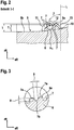
- Grooves 7 are arranged on the surface 6a of the basic elevation, which are parallel and spaced apart and which run in the circumferential direction UR of the tread ( 2, 3 ).
- the grooves 7 can form an angle ⁇ with the circumferential direction of the pneumatic vehicle tire, which is in a range from 0 ° to 20 °.
- the grooves 7 have a depth 8 of 0.7 to 0.9 mm, preferably 0.8 mm.
- the width 9 of the grooves is 0.9-1.1 mm, preferably 1 mm.
- the mutually facing flanks 7a of two adjacent grooves 7 are at least 0.5 to 1.5 mm apart, preferably 1 mm apart.
- the two Flanks 7a of a groove 7 merge into the groove base 7b by means of radii.
- the groove base 7b is formed approximately parallel to the outer contour / envelope of the base lift 6.
- the groove flanks 7a are approximately perpendicular to the outer contour / envelope of the base elevation 6.
- the base elevations 6 are arranged within the floor contact area, so that the end of the base elevation 10 on the outside of the tread is located at a distance a 1 of 0.5% of the width B of the floor contact area measured in the axial direction aR from the edge L of the floor contact area.
- the base lift 6 has at its base in the longitudinal direction of the transverse groove 5 a width b1 of 8.3% to 9.2%, in particular 8.7% to 8.9%, of the width B of the ground contact area.
- Each transverse groove 5 has a groove base 5b and at its deepest point in the radial direction a depth T 1 ( Fig.
- the basic elevation 6 has at its highest point a radial height T which corresponds to the condition T 1 mm - (0.5 mm to T 1 mm / 2), preferably T 1 mm - 1.2 mm. Due to the basic elevation 6, the depth of each transverse groove 5 in the radial direction rR is local to a depth T 2 ( Fig. 2 ) which is 1.0 mm to 1.4 mm, in particular 1.1 mm to 1.3 mm, and particularly preferably 1.2 mm.
- the outer contour of the basic elevation - viewed in its longitudinal section - has three sections 11, 12, 13: a first section 11 pointing towards the center of the tread, a central, second section 12 and a third section 13 pointing towards the outside of the tread.
- the section 11 pointing towards the center of the tread is formed from one or more radii and merges into the second section 12, the central section of the base elevation 6.
- This central, second section 12 forms a cover surface which is approximately contour-parallel to the jacket-shaped tread surface.
- the third section 13 is formed as a straight line which ends in the groove base 5b.
- the straight line forms an angle ⁇ between 43 ° and 47 ° with the radial direction rR.
- a transition region can be formed between the second section and the third section 12.
- the grooves 7 are arranged in the first and second sections 11, 12 of the base lift 6, the third section 13 has no or only a few grooves 7.
Landscapes
- Engineering & Computer Science (AREA)
- Mechanical Engineering (AREA)
- Tires In General (AREA)
Description
- Die Erfindung betrifft einen Fahrzeugluftreifen in Radialbauart mit einem Laufstreifen mit zumindest einer schulterseitigen Profilblockreihe, welche über ihre Umfangserstreckung mit einer Vielzahl von Querrillen versehen ist, welche die Profilblockreihe in Schulterblöcke gliedern, wobei in jeder Querrille eine Grundanhebung ausgebildet ist, welche in Umfangsrichtung aufeinanderfolgende Schulterblöcke aneinander anbindet und wobei der Laufstreifen eine Bodenaufstandsfläche mit einer Breite aufweist, deren einer Rand innerhalb der schulterseitigen Profilblockreihe liegt.
- Grundanhebungen sind dem Fachmann bekannt. Die Grundanhebung wird beispielsweise ebenfalls als "Verbindungssteg" oder als "Tie Bar" bezeichnet und ist ein Verbindungssteg zwischen zwei in Umfangsrichtung hintereinander angeordneten Profilblöcken und dient der Erhöhung der Stabilität des Laufstreifenprofils im Schulterbereich.
- Ein Fahrzeugluftreifen der eingangs genannten Art ist aus der
DE 10 2015 200 207 A1 bekannt. Der Laufstreifen des Fahrzeugluftreifens weist eine schulterseitige Profilblockreihe mit Querrillen auf, in welchen jeweils eine die benachbarten Schulterblöcke aneinander anbindende Grundanhebung ausgebildet ist. Die Grundanhebung weist zum Rillengrund der Querrille abfallende, treppenartig gestufte, seitliche Flanken auf. Diese Grundanhebungen sollen neben der Erhöhung der Stabilität der Schulterblöcke ferner einen gewissen Verzahnungseffekt beim Fahren auf weichem Untergrund, beispielsweise auf Schnee, ermöglichen. - Ein weiterer Fahrzeugluftreifen der eingangs genannten Art ist aus der
EP 2 338 702 A1 bekannt. Der Laufstreifen dieses Fahrzeugluftreifens weist unterschiedliche Profilstrukturen in den Laufstreifenhälften auf, wobei der Reifen in einen Reifeninnenschulterbereich und in einen Reifenaußenschulterbereich aufgeteilt ist. Im Außenschulterbereich ist in den Querrillen örtlich jeweils eine Grundanhebung ausgebildet, welche die einander zugewandten Quernutflanken zweier hintereinander angeordneter Profilblöcke miteinander verbindet. - Derartige Grundanhebungen haben infolge der größeren Umfangssteifigkeit der schulterseitigen Blöcke positive Auswirkungen auf die Handlingeigenschaften, insbesondere auch bei Kurvenfahrt.
- Weitere Fahrzeugluftreifen mit einem Laufstreifen mit einer Profilblockreihen, welche Querrillen mit Grundanhebungen aufweisen, sind beispielsweise aus der
EP 1 974 957 A1 , derDE 10 2010 016 978 A1 und derJP 2011 084 254 A EP 1 974 957 A1 weisen jeweils eine zum Rillengrund der Querrille abfallende, treppenartig gestufte, seitliche Flanke auf, welche sich vorteilhaft auf die Griffeigenschaften auf mit Matsch, Schlamm oder Schnee bedecktem Untergrund auswirken sol. Die in derDE 10 2010 016 978 A1 in Querrillen vorgesehenen Grundanhebungen weisen jeweils an die Profilblöcke angrenzende Seitenteile und einen zwischen diesen befindlichen Basisteil auf, wobei diese Teile eine sattelförmige Vertiefung an der jeweiligen Grundanhebung mitbilden. Solche Grundanhebungen sollen eine gute Querentwässerung ermöglichen. Die aus derJP 2011 084 254 A - Der Erfindung liegt die Aufgabe zu Grunde, einen Fahrzeugluftreifen der eingangs genannten Art derart auszuführen, dass dessen Handlingeigenschaften, insbesondere bei Kurvenfahrt bei hoher Geschwindigkeit weiter verbessert sind.
- Die gestellte Aufgabe wird erfindungsgemäß dadurch gelöst, dass die Grundanhebung, im Längsschnitt der Querrille betrachtet, zumindest über den Großteil ihrer Erstreckung eine radial nach außen gebogen verlaufende Oberfläche aufweist, welche von in der Grundanhebung ausgebildeten Nuten unterbrochen ist, wobei die Nuten parallel zueinander und unter einen Winkel von 0° bis 20° zur Umfangsrichtung des Fahrzeugluftreifens verlaufen.
- Gemäß der Erfindung ist in jeder Querrille wenigstens einer schulterseitigen Profilblockreihe, vorzugsweise der außenschulterseitigen Profilblockreihe, eine Grundanhebung ausgebildet, dessen Oberfläche durch parallele Nuten profiliert ausgebildet ist. Diese zusätzliche Profilierung der Grundanhebung bewirkt zwei Vorteile. Ein erster Vorteil ist darin zu sehen, dass durch die profilierte Oberfläche der Grundanhebung durch etwa in Umfangsrichtung ausgerichtete Nuten zusätzliche Kanten zur Verfügung gestellt sind, welche die Quertraktion insbesondere bei Kurvenfahrten bei hoher Geschwindigkeit signifikant verbessert. Ein zweiter Vorteil ist darin zu sehen, dass die Oberfläche der Grundanhebung durch die Profilierung vergrößert ist, wodurch die Wärmeabführung und somit die Kühlwirkung verbessert ist. Die Gefahr von sogenannten "Auskochungen" ist verringert.
- Im Bereich der radial nach außen gebogen verlaufenden Oberfläche treten insbesondere bei Kurvenfahrt große Kräfte auf, so dass durch die vorgenannte Querschnittsgeometrie der Grundanhebung eine mögliche Kerbwirkung reduziert wird. Zudem wird die Entwässerung der Querrillen verbessert.
- In einer bevorzugten Ausführung der Erfindung liegt die Grundanhebung auf dem Rand der Bodenaufstandsfläche. Alternativ befindet sich das laufstreifenaußenseitige Ende der Grundanhebung entweder am Rand der Bodenaufstandsfläche oder vom Rand der Bodenaufstandsfläche in einem in axialer Richtung gemessenen Abstand von bis zu 1% der Breite der Bodenaufstandsfläche. Durch die Anordnung der Grundanhebung im Bereich des Randes der Breite der Bodenaufstandsfläche ist die Schulterblockreihe wirkungsvoll versteift und bei Kurvenfahrten bei hoher Geschwindigkeit kommt die profilierte Grundanhebung in Kontakt mit der Oberfläche der Fahrbahn/des Untergrundes und verbessert die Quertraktion. Insbesondere bei tiefen Untergründen wie bei Schlamm ist die Quertraktion verbessert. Bei winterlichen Verhältnissen wird der Schnee besser in der Querrille gehalten, wodurch die Schnee-Schnee-Reibung verbessert ist.
- Besonders vorteilhaft ist es, wenn der Abstand bis zu 0,5%, insbesondere 0,5%, der Breite der Bodenaufstandsfläche beträgt. Durch die Anordnung der Grundanhebung im Bereich des Randes der Breite der Bodenaufstandsfläche ist die Schulterblockreihe besonders wirkungsvoll versteift und bei Kurvenfahrten bei hoher Geschwindigkeit kommt die profilierte Grundanhebung in optimalen Kontakt mit der Fahrbahnoberfläche. Hierdurch ist der beste Kompromiss zwischen Querentwässerung und Erhöhung der Stabilität des Laufstreifenprofils im Schulterbereich erhalten.
- Zweckmäßig ist es, wenn Nuten eine Tiefe von 0,4 bis 1,2 mm, bevorzugt von 0,7 bis 0,9 mm, besonders bevorzugt von 0,8 mm, aufweisen. Eine vorgenannte Tiefe der Nuten ist gut produzierbar und bildet einen Kompromiss auf hohem Niveau zwischen Höhe der Grundanhebung und verbesserter Traktion.
- Zweckmäßig ist es, wenn die Nuten eine Breite von 0,5 bis 1,4 mm, bevorzugt von 0,9 bis 1,1 mm, besonders bevorzugt von 1 mm, aufweisen. Eine vorgenannte Breite der Nuten ist gut produzierbar und bildet einen Kompromiss auf hohem Niveau zwischen Höhe der Grundanhebung und verbesserter Traktion.
- Die versteifende Wirkung der am Rand der Bodenaufstandsfläche positionierten Grundanhebung auf die schulterseitige Profilblockreihe ist besonders vorteilhaft, wenn die Grundanhebung an ihrer Basis in axialer Richtung eine Breite von 8,3% bis 9,2%, insbesondere von 8,7% bis 8,9%, der Breite der Bodenaufstandsfläche aufweist. Insbesondere für die erwähnte versteifende Wirkung bei Kurvenfahrt sind Grundanhebungen mit einer solchen Breite von Vorteil.
- Vorteilhaft ist es, wenn die Außenkontur der Grundanhebung - in deren Längsschnitt betrachtet - einen zur Laufstreifenmitte weisenden Abschnitt aus einem oder aus mehreren Radien aufweist und einen mittigen, parallel zur mantelförmigen Laufstreifenoberfläche ausgebildeten Abschnitt aufweist, in welche die Nuten eingebracht sind und wenn die Außenkontur einen dritten Abschnitt aufweist, welcher zur Laufstreifenaußenseite weist und in einer Geraden am Rillengrund endet, wobei die Gerade mit der radialen Richtung einen Winkel zwischen 40° und 50°, vorzugsweise von etwa 45°, einschließt. In diesem Bereich treten insbesondere bei Kurvenfahrt große Kräfte auf, so dass durch die vorgenannte Querschnittsgeometrie der Grundanhebung eine mögliche Kerbwirkung reduziert wird. Zudem wird die Entwässerung der Querrillen verbessert.
- Eine weitere bevorzugt Ausführung ist dadurch gekennzeichnet, dass die Grundanhebung an ihrer höchsten Stelle eine radiale Höhe in Millimeter aufweist, welche der Bedingung

- Weitere Merkmale, Vorteile und Einzelheiten der Erfindung werden nun anhand der Zeichnungen, welche schematisch ein Ausführungsbeispiel der Erfindung zeigen, näher erläutert. Dabei zeigen die
-
Fig. 1 eine vereinfachte Draufsicht auf einen Umfangsabschnitt eines Laufstreifens eines Fahrzeugluftreifens mit einer Ausführungsvariante der Erfindung und -
Fig. 2 einen Schnitt entlang der Linie I-I derFig. 1 , -
Fig. 3 eine Vergrößerung eines Ausschnitts der Grundanhebung derFig. 2 . - Die
Fig. 1 zeigt eine Draufsicht auf einen Umfangsabschnitt eines Laufstreifens eines erfindungsgemäßen Fahrzeugluftreifens in Radialbauart für Personenkraftwagen, Vans oder Light-Trucks. Der Laufstreifen ist profiliert und weist in jeder Schulter eine schulterseitige Profilblockreihe 1 und im mittigen Bereich des Laufstreifens Laufstreifenbänder 2 auf, welche durch Umfangsrillen 3 voneinander und von den schulterseitigen Profilblockreihen 1 begrenzt sind. Die Profilblöcke 4 der Schulter sind durch eine Vielzahl von über den Rand der Bodenaufstandsfläche hinausverlaufenden Querrillen 5 voneinander getrennt, so dass die Profilblöcke 1 der Reifenschulter in Umfangsrichtung UR hintereinander angeordnet sind.
Die Ränder der Bodenaufstandsfläche des Laufstreifens sind inFig. 1 undFig. 2 jeweils durch eine gestrichelte Linie L gekennzeichnet, wobei die Bodenaufstandsfläche dem statisch ermittelten Footprint (Last bei 70 % der maximalen Tragfähigkeit bei einem Innendruck von 85 % nach E.T.R.T.O.-Norm) entspricht. Die Bodenaufstandsfläche wird auch als TW45 bezeichnet. Die Bodenaufstandsfläche weist in axialer Richtung aR eine Breite B auf (Fig. 1 ) und endet in bekannter Weise als über den Laufstreifen umlaufender Rand L in den schulterseitigen Profilblockreihen 1. Die schulterseitigen Profilblockreihen 1 liegen somit teilweise innerhalb der Bodenaufstandsfläche und teilweise außerhalb der Bodenaufstandsfläche. - Die Querrillen 5 sind in Draufsicht parallel zueinander sowie leicht bogenförmig verlaufend. Die Querrillen 5 können in Draufsicht auch gerade sowie ferner in axialer Richtung oder unter einem von der axialen Richtung um bis zu 35° abweichenden Winkel verlaufen. An der Oberfläche der außerhalb der Bodenaufstandsfläche befindlichen Schulterblöcken sind die Querrillen 5 in Umfangsrichtung jeweils durch zwei Rillenkanten 5a begrenzt, welche bis zur Umfangsrille 2 sowie beim gezeigten Ausführungsbeispiel in Draufsicht parallel zueinander verlaufen. Die Rillenkanten 5a können in an sich bekannter Weise angefast sein.
- In jeder Querrille 5 ist eine Grundanhebung 6 ausgebildet, welche in Umfangsrichtung UR aufeinanderfolgende Schulterblöcke 4 aneinander anbindet. Die Grundanhebungen 6 sind derart in den Querrillen 5 positioniert, dass sie in Umfangsrichtung UR miteinander fluchten. Auf der Oberfläche 6a der Grundanhebung sind Nuten 7 angeordnet, welche parallel und beabstandet zueinander ausgebildet sind und welche in Umfangsrichtung UR des Laufstreifens verlaufen (
Fig. 2, Fig. 3 ). Die Nuten 7 können in anderen Ausführungen der Erfindung mit der Umfangsrichtung des Fahrzeugluftreifens einen Winkel α einschließen, welcher in einem Bereich von 0° bis 20° liegt. Die Nuten 7 weisen eine Tiefe 8 von 0,7 bis 0,9 mm, bevorzugt von 0,8 mm auf. Die Breite 9 der Nuten beträgt 0,9 - 1,1 mm, bevorzugt 1 mm. Die einander zugewandten Flanken 7a zweier benachbarter Nuten 7 sind mindestens 0,5 bis 1,5 mm, bevorzugt 1 mm voneinander beabstandet. Die beiden Flanken 7a einer Nut 7 gehen mittels Radien in den Nutgrund 7b über. Der Nutgrund 7b ist etwa parallel zur Außenkontur / Einhüllenden der Grundanhebung 6 ausgebildet. Die Rillenflanken 7a stehen etwa senkrecht auf der Außenkontur / Einhüllenden der Grundanhebung 6.
Die Gundanhebungen 6 sind innerhalb der Bodenaufstandsfläche angeordnet, so dass das laufstreifenaußenseitiges Ende der Grundanhebung 10 vom Rand L der Bodenaufstandsfläche in einem in axialer Richtung aR gemessenen Abstand a1 von 0,5 % der Breite B der Bodenaufstandsfläche befindet. Die Grundanhebung 6 weist an ihrer Basis in Längsrichtung der Querrille 5 eine Breite b1 von 8,3% bis 9,2%, insbesondere von 8,7% bis 8,9%, der Breite B der Bodenaufstandsfläche auf. Jede Querrille 5 weist einen Rillengrund 5b sowie an ihrer tiefsten Stelle in radialer Richtung eine Tiefe T1 (Fig. 2 ) von 6,0 mm bis 9,0 mm auf, wobei die Tiefe T1 beim gezeigten Ausführungsbeispiel der jeweils vorgesehenen Profiltiefe des Laufstreifens und damit der Tiefe der Umfangsrille 2 entspricht. Die Grundanhebung 6 weist an ihrer höchsten Stelle eine radiale Höhe T auf, welche der Bedingung T1mm - (0,5mm bis T1mm/2), bevorzugt T1mm - 1,2mm entspricht. Durch die Grundanhebung 6 ist die Tiefe jeder Querrille 5 in radialer Richtung rR lokal bis auf eine Tiefe T2 (Fig. 2 ) verringert, welche 1,0 mm bis 1,4 mm, insbesondere 1,1 mm bis 1,3 mm, und besonders bevorzugter Weise 1,2 mm beträgt.
Die Außenkontur der Grundanhebung - in deren Längsschnitt betrachtet - weist drei Abschnitte 11, 12, 13 auf: einen zur Laufstreifenmitte weisenden ersten Abschnitt 11, einen mittigen, zweiten Abschnitt 12 und einen zur Laufstreifenaußenseite weisenden dritten Abschnitt 13. Der zur Laufstreifenmitte weisende Abschnitt 11 ist aus einem oder aus mehreren Radien gebildet und geht in den zweiten Abschnitt 12, den mittigen Abschnitt der Grundanhebung 6 über. Dieser mittige, zweite Abschnitt 12 bildet eine Deckfläche, welche etwa konturparallel zur mantelförmigen Laufstreifenfläche ausgebildet ist. Der dritte Abschnitt 13 ist als Gerade ausgebildet, welche im Rillengrund 5b endet. Die Gerade schließt mit der radialen Richtung rR einen Winkel β zwischen 43° und 47° ein. Zwischen dem zweiten Abschnitt und dem dritten Abschnitt 12 kann ein Übergangsbereich ausgebildet sein. Die Nuten 7 sind in dem ersten und zweiten Abschnitt 11, 12 der Grundanhebung 6 angeordnet, der dritte Abschnitt 13 weist keine oder nur wenige Nuten 7 auf. -
- 1 Profilblockreihe
- 2 Laufstreifenband
- 3 Umfangsrille
- 4 Profilblock / Schulterblock
- 5 Querrille
- 5a Rillenkante der Querrille
- 5b Rillengrund der Querrille
- 6 Grundanhebung
- 6a Oberfläche der Grundanhebung
- 7 Nut
- 7a Nutflanke
- 7b Nutgrund
- 8 Tiefe der Nut
- 9 Breite der Nut
- 10 laufstreifenaußenseitiges Ende der Grundanhebung
- 11 erster Abschnitt der Grundanhebung
- 12 zweiter Abschnitt der Grundanhebung
- 13 dritter Abschnitt der Grundanhebung
- L Rand der Bodenaufstandsfläche
- B Breite der Bodenaufstandsfläche
- T Höhe der Grundanhebung
- a1 Abstand des laufstreifenaußenseitigen Endes der Grundanhebung zum Rand
- b1 Länge der Grundanhebung
- T1 maximale Profiltiefe der Querrille
- α, β Winkel
Claims (8)
- Fahrzeugluftreifen in Radialbauart mit einem Laufstreifen mit zumindest einer schulterseitigen Profilblockreihe (1), welche über ihre Umfangserstreckung mit einer Vielzahl von Querrillen (5) versehen ist, welche die Profilblockreihe (1) in Schulterblöcke (4) gliedern, wobei in jeder Querrille (5) eine Grundanhebung (6) ausgebildet ist, welche in Umfangsrichtung aufeinanderfolgende Schulterblöcke (4) aneinander anbindet und wobei der Laufstreifen eine Bodenaufstandsfläche mit einer Breite (B) aufweist, deren einer Rand (L) innerhalb der schulterseitigen Profilblockreihe (1) liegt,
dadurch gekennzeichnet,
dass die Grundanhebung (6), im Längsschnitt der Querrille (5) betrachtet, zumindest über den Großteil ihrer Erstreckung eine radial nach außen gebogen verlaufende Oberfläche aufweist, welche von in der Grundanhebung (6) ausgebildeten Nuten (7) unterbrochen ist, wobei die Nuten (7) parallel zueinander und unter einen Winkel (α) von 0° bis 20° zur Umfangsrichtung (UR) des Fahrzeugluftreifens verlaufen. - Fahrzeugluftreifen nach Anspruch 1, dadurch gekennzeichnet, dass die Gundanhebung (6) auf dem Rand (L) der Bodenaufstandsfläche liegt oder alternativ dass das laufstreifenaußenseitiges Ende (10) der Grundanhebung (6) sich entweder am Rand (L) der Bodenaufstandsfläche oder vom Rand (L) der Bodenaufstandsfläche in einem in axialer Richtung (aR) gemessenen Abstand (a1) von bis zu 1% der Breite (B) der Bodenaufstandsfläche befindet.
- Fahrzeugluftreifen nach Anspruch 2, dadurch gekennzeichnet, dass der Abstand (a1) bis zu 0,5%, insbesondere 0,5%, der Breite (B) der Bodenaufstandsfläche beträgt.
- Fahrzeugluftreifen nach einem oder mehreren der vorangehenden Ansprüche, dadurch gekennzeichnet, dass die Nuten (7) eine Tiefe (8) von 0,4 bis 1,2 mm, bevorzugt von 0,7 bis 0,9 mm, besonders bevorzugt von 0,8 mm, aufweisen.
- Fahrzeugluftreifen nach einem oder mehreren der vorangehenden Ansprüche, dadurch gekennzeichnet, dass die Nuten (7) eine Breite (9) von 0,5 bis 1,4 mm, bevorzugt von 0,9 bis 1,1 mm, besonders bevorzugt von 1 mm, aufweisen.
- Fahrzeugluftreifen nach einem oder mehreren der vorangehenden Ansprüche, dadurch gekennzeichnet, dass die Grundanhebung (6) an ihrer Basis in Längsrichtung der Querrille eine Breite (b1) von 8,3% bis 9,2%, insbesondere von 8,7% bis 8,9%, der Breite (B) der Bodenaufstandsfläche aufweist.
- Fahrzeugluftreifen nach einem oder mehreren der vorangehenden Ansprüche, dadurch gekennzeichnet, dass die Außenkontur der Grundanhebung (6) - in deren Längsschnitt betrachtet - aus drei Abschnitten (11, 12, 13) gebildet ist, einen ersten Abschnitt (11), welcher zur Laufstreifenmitte weist und aus einem oder aus mehreren Radien gebildet ist, einem zweiten, mittig Abschnitt (12) der Grundanhebung (6), welcher konturparallel zur mantelförmigen Laufstreifenfläche verläuft und einem dritten, zur Laufstreifenaußenseite weisenden Abschnitt (13/10), welcher als Gerade im Rillengrund (5b) endet, wobei die Gerade (13) mit der radialen Richtung (rR) einen Winkel (β) zwischen 35° und 55°, vorzugsweise zwischen 43° und 47°, einschließt.
- Fahrzeugluftreifen nach einem oder mehreren der vorangehenden Ansprüche, dadurch gekennzeichnet, dass die Grundanhebung (6) an ihrer höchsten Stelle eine radiale Höhe (T) in Millimeter aufweist, welche der Bedingung

Applications Claiming Priority (1)
| Application Number | Priority Date | Filing Date | Title |
|---|---|---|---|
| DE102017210181.4A DE102017210181A1 (de) | 2017-06-19 | 2017-06-19 | Fahrzeugluftreifen |
Publications (2)
| Publication Number | Publication Date |
|---|---|
| EP3418076A1 EP3418076A1 (de) | 2018-12-26 |
| EP3418076B1 true EP3418076B1 (de) | 2020-03-04 |
Family
ID=61868415
Family Applications (1)
| Application Number | Title | Priority Date | Filing Date |
|---|---|---|---|
| EP18165375.9A Active EP3418076B1 (de) | 2017-06-19 | 2018-04-03 | Fahrzeugluftreifen |
Country Status (2)
| Country | Link |
|---|---|
| EP (1) | EP3418076B1 (de) |
| DE (1) | DE102017210181A1 (de) |
Families Citing this family (1)
| Publication number | Priority date | Publication date | Assignee | Title |
|---|---|---|---|---|
| CN114537052A (zh) * | 2020-11-18 | 2022-05-27 | 新东岳集团有限公司 | 一种摩托车轮胎 |
Family Cites Families (6)
| Publication number | Priority date | Publication date | Assignee | Title |
|---|---|---|---|---|
| DE102006047324B4 (de) * | 2006-10-06 | 2014-03-13 | Continental Reifen Deutschland Gmbh | Laufstreifenprofil eines Fahrzeugluftreifens |
| DE102007015354A1 (de) * | 2007-03-30 | 2008-10-02 | Continental Aktiengesellschaft | Fahrzeugluftreifen |
| JP2011084254A (ja) * | 2009-10-19 | 2011-04-28 | Sumitomo Rubber Ind Ltd | 空気入りタイヤ |
| DE102009059169A1 (de) | 2009-12-16 | 2011-06-22 | Continental Reifen Deutschland GmbH, 30165 | Fahrzeugluftreifen |
| DE102010016978A1 (de) * | 2010-05-18 | 2011-11-24 | Continental Reifen Deutschland Gmbh | Fahrzeugluftreifen |
| DE102015200207A1 (de) * | 2015-01-09 | 2016-07-14 | Continental Reifen Deutschland Gmbh | Fahrzeugluftreifen |
-
2017
- 2017-06-19 DE DE102017210181.4A patent/DE102017210181A1/de not_active Withdrawn
-
2018
- 2018-04-03 EP EP18165375.9A patent/EP3418076B1/de active Active
Non-Patent Citations (1)
| Title |
|---|
| None * |
Also Published As
| Publication number | Publication date |
|---|---|
| EP3418076A1 (de) | 2018-12-26 |
| DE102017210181A1 (de) | 2018-12-20 |
Similar Documents
| Publication | Publication Date | Title |
|---|---|---|
| DE69611341T2 (de) | Kraftfahrzeug-Luftreifen mit einem Laufflächenprofil besonders geeignet zum Laufen auf schneebedeckten Strassenoberflächen | |
| EP3388256B1 (de) | Fahrzeugluftreifen | |
| EP2646264B1 (de) | Fahrzeugluftreifen | |
| EP3181378B1 (de) | Fahrzeugluftreifen | |
| EP3256334B1 (de) | Fahrzeugluftreifen | |
| EP3300926B1 (de) | Fahrzeugluftreifen | |
| EP3421264B1 (de) | Fahrzeugluftreifen | |
| EP3620311B1 (de) | Fahrzeugluftreifen | |
| EP2217455B1 (de) | Fahrzeugluftreifen | |
| EP3256335B1 (de) | Fahrzeugluftreifen | |
| EP3009276B1 (de) | Fahrzeugluftreifen | |
| EP4577416A1 (de) | Fahrzeugluftreifen | |
| EP4244079B1 (de) | Fahrzeugluftreifen | |
| EP4058304B1 (de) | Fahrzeugluftreifen | |
| EP3750723B1 (de) | Fahrzeugluftreifen | |
| EP2138329B1 (de) | Laufflächenprofil für einen Fahrzeugluftreifen | |
| EP3450213A1 (de) | Fahrzeugluftreifen | |
| DE102008029659A1 (de) | Fahrzeugluftreifen | |
| EP3300925B1 (de) | Fahrzeugluftreifen | |
| EP2138328B1 (de) | Fahrzeugluftreifen | |
| EP3831619B1 (de) | Fahrzeugluftreifen | |
| EP3418077B1 (de) | Fahrzeugluftreifen | |
| EP3686034B1 (de) | Fahrzeugluftreifen | |
| EP2142388B1 (de) | Fahrzeugluftreifen | |
| EP3418076A1 (de) | Fahrzeugluftreifen |
Legal Events
| Date | Code | Title | Description |
|---|---|---|---|
| PUAI | Public reference made under article 153(3) epc to a published international application that has entered the european phase |
Free format text: ORIGINAL CODE: 0009012 |
|
| STAA | Information on the status of an ep patent application or granted ep patent |
Free format text: STATUS: THE APPLICATION HAS BEEN PUBLISHED |
|
| AK | Designated contracting states |
Kind code of ref document: A1 Designated state(s): AL AT BE BG CH CY CZ DE DK EE ES FI FR GB GR HR HU IE IS IT LI LT LU LV MC MK MT NL NO PL PT RO RS SE SI SK SM TR |
|
| AX | Request for extension of the european patent |
Extension state: BA ME |
|
| STAA | Information on the status of an ep patent application or granted ep patent |
Free format text: STATUS: REQUEST FOR EXAMINATION WAS MADE |
|
| 17P | Request for examination filed |
Effective date: 20190626 |
|
| RBV | Designated contracting states (corrected) |
Designated state(s): AL AT BE BG CH CY CZ DE DK EE ES FI FR GB GR HR HU IE IS IT LI LT LU LV MC MK MT NL NO PL PT RO RS SE SI SK SM TR |
|
| RIC1 | Information provided on ipc code assigned before grant |
Ipc: B60C 11/03 20060101ALI20190909BHEP Ipc: B60C 11/13 20060101AFI20190909BHEP |
|
| GRAP | Despatch of communication of intention to grant a patent |
Free format text: ORIGINAL CODE: EPIDOSNIGR1 |
|
| STAA | Information on the status of an ep patent application or granted ep patent |
Free format text: STATUS: GRANT OF PATENT IS INTENDED |
|
| INTG | Intention to grant announced |
Effective date: 20191114 |
|
| GRAS | Grant fee paid |
Free format text: ORIGINAL CODE: EPIDOSNIGR3 |
|
| GRAA | (expected) grant |
Free format text: ORIGINAL CODE: 0009210 |
|
| STAA | Information on the status of an ep patent application or granted ep patent |
Free format text: STATUS: THE PATENT HAS BEEN GRANTED |
|
| AK | Designated contracting states |
Kind code of ref document: B1 Designated state(s): AL AT BE BG CH CY CZ DE DK EE ES FI FR GB GR HR HU IE IS IT LI LT LU LV MC MK MT NL NO PL PT RO RS SE SI SK SM TR |
|
| REG | Reference to a national code |
Ref country code: GB Ref legal event code: FG4D Free format text: NOT ENGLISH |
|
| REG | Reference to a national code |
Ref country code: CH Ref legal event code: EP |
|
| REG | Reference to a national code |
Ref country code: AT Ref legal event code: REF Ref document number: 1239947 Country of ref document: AT Kind code of ref document: T Effective date: 20200315 |
|
| REG | Reference to a national code |
Ref country code: DE Ref legal event code: R096 Ref document number: 502018000866 Country of ref document: DE |
|
| REG | Reference to a national code |
Ref country code: IE Ref legal event code: FG4D Free format text: LANGUAGE OF EP DOCUMENT: GERMAN |
|
| PG25 | Lapsed in a contracting state [announced via postgrant information from national office to epo] |
Ref country code: RS Free format text: LAPSE BECAUSE OF FAILURE TO SUBMIT A TRANSLATION OF THE DESCRIPTION OR TO PAY THE FEE WITHIN THE PRESCRIBED TIME-LIMIT Effective date: 20200304 Ref country code: NO Free format text: LAPSE BECAUSE OF FAILURE TO SUBMIT A TRANSLATION OF THE DESCRIPTION OR TO PAY THE FEE WITHIN THE PRESCRIBED TIME-LIMIT Effective date: 20200604 Ref country code: FI Free format text: LAPSE BECAUSE OF FAILURE TO SUBMIT A TRANSLATION OF THE DESCRIPTION OR TO PAY THE FEE WITHIN THE PRESCRIBED TIME-LIMIT Effective date: 20200304 |
|
| REG | Reference to a national code |
Ref country code: NL Ref legal event code: MP Effective date: 20200304 |
|
| PG25 | Lapsed in a contracting state [announced via postgrant information from national office to epo] |
Ref country code: LV Free format text: LAPSE BECAUSE OF FAILURE TO SUBMIT A TRANSLATION OF THE DESCRIPTION OR TO PAY THE FEE WITHIN THE PRESCRIBED TIME-LIMIT Effective date: 20200304 Ref country code: SE Free format text: LAPSE BECAUSE OF FAILURE TO SUBMIT A TRANSLATION OF THE DESCRIPTION OR TO PAY THE FEE WITHIN THE PRESCRIBED TIME-LIMIT Effective date: 20200304 Ref country code: GR Free format text: LAPSE BECAUSE OF FAILURE TO SUBMIT A TRANSLATION OF THE DESCRIPTION OR TO PAY THE FEE WITHIN THE PRESCRIBED TIME-LIMIT Effective date: 20200605 Ref country code: HR Free format text: LAPSE BECAUSE OF FAILURE TO SUBMIT A TRANSLATION OF THE DESCRIPTION OR TO PAY THE FEE WITHIN THE PRESCRIBED TIME-LIMIT Effective date: 20200304 Ref country code: BG Free format text: LAPSE BECAUSE OF FAILURE TO SUBMIT A TRANSLATION OF THE DESCRIPTION OR TO PAY THE FEE WITHIN THE PRESCRIBED TIME-LIMIT Effective date: 20200604 |
|
| REG | Reference to a national code |
Ref country code: LT Ref legal event code: MG4D |
|
| PG25 | Lapsed in a contracting state [announced via postgrant information from national office to epo] |
Ref country code: NL Free format text: LAPSE BECAUSE OF FAILURE TO SUBMIT A TRANSLATION OF THE DESCRIPTION OR TO PAY THE FEE WITHIN THE PRESCRIBED TIME-LIMIT Effective date: 20200304 |
|
| PG25 | Lapsed in a contracting state [announced via postgrant information from national office to epo] |
Ref country code: SK Free format text: LAPSE BECAUSE OF FAILURE TO SUBMIT A TRANSLATION OF THE DESCRIPTION OR TO PAY THE FEE WITHIN THE PRESCRIBED TIME-LIMIT Effective date: 20200304 Ref country code: SM Free format text: LAPSE BECAUSE OF FAILURE TO SUBMIT A TRANSLATION OF THE DESCRIPTION OR TO PAY THE FEE WITHIN THE PRESCRIBED TIME-LIMIT Effective date: 20200304 Ref country code: EE Free format text: LAPSE BECAUSE OF FAILURE TO SUBMIT A TRANSLATION OF THE DESCRIPTION OR TO PAY THE FEE WITHIN THE PRESCRIBED TIME-LIMIT Effective date: 20200304 Ref country code: LT Free format text: LAPSE BECAUSE OF FAILURE TO SUBMIT A TRANSLATION OF THE DESCRIPTION OR TO PAY THE FEE WITHIN THE PRESCRIBED TIME-LIMIT Effective date: 20200304 Ref country code: RO Free format text: LAPSE BECAUSE OF FAILURE TO SUBMIT A TRANSLATION OF THE DESCRIPTION OR TO PAY THE FEE WITHIN THE PRESCRIBED TIME-LIMIT Effective date: 20200304 Ref country code: CZ Free format text: LAPSE BECAUSE OF FAILURE TO SUBMIT A TRANSLATION OF THE DESCRIPTION OR TO PAY THE FEE WITHIN THE PRESCRIBED TIME-LIMIT Effective date: 20200304 Ref country code: ES Free format text: LAPSE BECAUSE OF FAILURE TO SUBMIT A TRANSLATION OF THE DESCRIPTION OR TO PAY THE FEE WITHIN THE PRESCRIBED TIME-LIMIT Effective date: 20200304 Ref country code: PT Free format text: LAPSE BECAUSE OF FAILURE TO SUBMIT A TRANSLATION OF THE DESCRIPTION OR TO PAY THE FEE WITHIN THE PRESCRIBED TIME-LIMIT Effective date: 20200729 Ref country code: IS Free format text: LAPSE BECAUSE OF FAILURE TO SUBMIT A TRANSLATION OF THE DESCRIPTION OR TO PAY THE FEE WITHIN THE PRESCRIBED TIME-LIMIT Effective date: 20200704 |
|
| REG | Reference to a national code |
Ref country code: DE Ref legal event code: R097 Ref document number: 502018000866 Country of ref document: DE |
|
| RAP2 | Party data changed (patent owner data changed or rights of a patent transferred) |
Owner name: CONTINENTAL REIFEN DEUTSCHLAND GMBH |
|
| PG25 | Lapsed in a contracting state [announced via postgrant information from national office to epo] |
Ref country code: MC Free format text: LAPSE BECAUSE OF FAILURE TO SUBMIT A TRANSLATION OF THE DESCRIPTION OR TO PAY THE FEE WITHIN THE PRESCRIBED TIME-LIMIT Effective date: 20200304 |
|
| PLBE | No opposition filed within time limit |
Free format text: ORIGINAL CODE: 0009261 |
|
| STAA | Information on the status of an ep patent application or granted ep patent |
Free format text: STATUS: NO OPPOSITION FILED WITHIN TIME LIMIT |
|
| PG25 | Lapsed in a contracting state [announced via postgrant information from national office to epo] |
Ref country code: LU Free format text: LAPSE BECAUSE OF NON-PAYMENT OF DUE FEES Effective date: 20200403 Ref country code: DK Free format text: LAPSE BECAUSE OF FAILURE TO SUBMIT A TRANSLATION OF THE DESCRIPTION OR TO PAY THE FEE WITHIN THE PRESCRIBED TIME-LIMIT Effective date: 20200304 |
|
| REG | Reference to a national code |
Ref country code: BE Ref legal event code: MM Effective date: 20200430 |
|
| 26N | No opposition filed |
Effective date: 20201207 |
|
| PG25 | Lapsed in a contracting state [announced via postgrant information from national office to epo] |
Ref country code: BE Free format text: LAPSE BECAUSE OF NON-PAYMENT OF DUE FEES Effective date: 20200430 Ref country code: SI Free format text: LAPSE BECAUSE OF FAILURE TO SUBMIT A TRANSLATION OF THE DESCRIPTION OR TO PAY THE FEE WITHIN THE PRESCRIBED TIME-LIMIT Effective date: 20200304 Ref country code: PL Free format text: LAPSE BECAUSE OF FAILURE TO SUBMIT A TRANSLATION OF THE DESCRIPTION OR TO PAY THE FEE WITHIN THE PRESCRIBED TIME-LIMIT Effective date: 20200304 |
|
| PG25 | Lapsed in a contracting state [announced via postgrant information from national office to epo] |
Ref country code: IE Free format text: LAPSE BECAUSE OF NON-PAYMENT OF DUE FEES Effective date: 20200403 |
|
| PG25 | Lapsed in a contracting state [announced via postgrant information from national office to epo] |
Ref country code: LI Free format text: LAPSE BECAUSE OF NON-PAYMENT OF DUE FEES Effective date: 20210430 Ref country code: CH Free format text: LAPSE BECAUSE OF NON-PAYMENT OF DUE FEES Effective date: 20210430 |
|
| PG25 | Lapsed in a contracting state [announced via postgrant information from national office to epo] |
Ref country code: TR Free format text: LAPSE BECAUSE OF FAILURE TO SUBMIT A TRANSLATION OF THE DESCRIPTION OR TO PAY THE FEE WITHIN THE PRESCRIBED TIME-LIMIT Effective date: 20200304 Ref country code: MT Free format text: LAPSE BECAUSE OF FAILURE TO SUBMIT A TRANSLATION OF THE DESCRIPTION OR TO PAY THE FEE WITHIN THE PRESCRIBED TIME-LIMIT Effective date: 20200304 Ref country code: CY Free format text: LAPSE BECAUSE OF FAILURE TO SUBMIT A TRANSLATION OF THE DESCRIPTION OR TO PAY THE FEE WITHIN THE PRESCRIBED TIME-LIMIT Effective date: 20200304 |
|
| PG25 | Lapsed in a contracting state [announced via postgrant information from national office to epo] |
Ref country code: MK Free format text: LAPSE BECAUSE OF FAILURE TO SUBMIT A TRANSLATION OF THE DESCRIPTION OR TO PAY THE FEE WITHIN THE PRESCRIBED TIME-LIMIT Effective date: 20200304 Ref country code: AL Free format text: LAPSE BECAUSE OF FAILURE TO SUBMIT A TRANSLATION OF THE DESCRIPTION OR TO PAY THE FEE WITHIN THE PRESCRIBED TIME-LIMIT Effective date: 20200304 |
|
| REG | Reference to a national code |
Ref country code: DE Ref legal event code: R081 Ref document number: 502018000866 Country of ref document: DE Owner name: CONTINENTAL REIFEN DEUTSCHLAND GMBH, DE Free format text: FORMER OWNER: CONTINENTAL REIFEN DEUTSCHLAND GMBH, 30165 HANNOVER, DE |
|
| REG | Reference to a national code |
Ref country code: AT Ref legal event code: MM01 Ref document number: 1239947 Country of ref document: AT Kind code of ref document: T Effective date: 20230403 |
|
| PGFP | Annual fee paid to national office [announced via postgrant information from national office to epo] |
Ref country code: GB Payment date: 20240419 Year of fee payment: 7 |
|
| PG25 | Lapsed in a contracting state [announced via postgrant information from national office to epo] |
Ref country code: AT Free format text: LAPSE BECAUSE OF NON-PAYMENT OF DUE FEES Effective date: 20230403 |
|
| PG25 | Lapsed in a contracting state [announced via postgrant information from national office to epo] |
Ref country code: AT Free format text: LAPSE BECAUSE OF NON-PAYMENT OF DUE FEES Effective date: 20230403 |
|
| PGFP | Annual fee paid to national office [announced via postgrant information from national office to epo] |
Ref country code: IT Payment date: 20240424 Year of fee payment: 7 |
|
| PGFP | Annual fee paid to national office [announced via postgrant information from national office to epo] |
Ref country code: DE Payment date: 20250430 Year of fee payment: 8 |
|
| PGFP | Annual fee paid to national office [announced via postgrant information from national office to epo] |
Ref country code: FR Payment date: 20250425 Year of fee payment: 8 |
|
| GBPC | Gb: european patent ceased through non-payment of renewal fee |
Effective date: 20250403 |
|
| PG25 | Lapsed in a contracting state [announced via postgrant information from national office to epo] |
Ref country code: GB Free format text: LAPSE BECAUSE OF NON-PAYMENT OF DUE FEES Effective date: 20250403 |
|
| PGFP | Annual fee paid to national office [announced via postgrant information from national office to epo] |
Ref country code: AT Payment date: 20260410 Year of fee payment: 5 |
|
| PG25 | Lapsed in a contracting state [announced via postgrant information from national office to epo] |
Ref country code: IT Free format text: LAPSE BECAUSE OF NON-PAYMENT OF DUE FEES Effective date: 20250403 |