EP3418018B1 - Method for producing a fibrous material impregnated with thermoplastic polymer - Google Patents
Method for producing a fibrous material impregnated with thermoplastic polymer Download PDFInfo
- Publication number
- EP3418018B1 EP3418018B1 EP18178996.7A EP18178996A EP3418018B1 EP 3418018 B1 EP3418018 B1 EP 3418018B1 EP 18178996 A EP18178996 A EP 18178996A EP 3418018 B1 EP3418018 B1 EP 3418018B1
- Authority
- EP
- European Patent Office
- Prior art keywords
- polymer
- fibers
- compression roller
- wick
- impregnation
- Prior art date
- Legal status (The legal status is an assumption and is not a legal conclusion. Google has not performed a legal analysis and makes no representation as to the accuracy of the status listed.)
- Active
Links
- 239000002657 fibrous material Substances 0.000 title claims description 91
- 229920001169 thermoplastic Polymers 0.000 title claims description 86
- 238000004519 manufacturing process Methods 0.000 title claims description 25
- 230000006835 compression Effects 0.000 claims description 222
- 238000007906 compression Methods 0.000 claims description 222
- 239000000835 fiber Substances 0.000 claims description 159
- 238000010438 heat treatment Methods 0.000 claims description 128
- 238000005470 impregnation Methods 0.000 claims description 113
- 239000004952 Polyamide Substances 0.000 claims description 93
- 229920002647 polyamide Polymers 0.000 claims description 93
- 238000000034 method Methods 0.000 claims description 90
- 229910052799 carbon Inorganic materials 0.000 claims description 89
- 229920000642 polymer Polymers 0.000 claims description 88
- OKTJSMMVPCPJKN-UHFFFAOYSA-N Carbon Chemical compound [C] OKTJSMMVPCPJKN-UHFFFAOYSA-N 0.000 claims description 84
- 239000000843 powder Substances 0.000 claims description 61
- 239000000203 mixture Substances 0.000 claims description 48
- 239000011521 glass Substances 0.000 claims description 39
- 239000011159 matrix material Substances 0.000 claims description 39
- 229920001601 polyetherimide Polymers 0.000 claims description 31
- 239000004416 thermosoftening plastic Substances 0.000 claims description 23
- 229920000049 Carbon (fiber) Polymers 0.000 claims description 21
- 239000004917 carbon fiber Substances 0.000 claims description 21
- 229920002530 polyetherether ketone Polymers 0.000 claims description 21
- 238000003490 calendering Methods 0.000 claims description 20
- 230000008018 melting Effects 0.000 claims description 20
- 238000002844 melting Methods 0.000 claims description 20
- -1 polypropylene Polymers 0.000 claims description 16
- 238000007493 shaping process Methods 0.000 claims description 16
- 229920006012 semi-aromatic polyamide Polymers 0.000 claims description 12
- 230000009477 glass transition Effects 0.000 claims description 9
- 229920002981 polyvinylidene fluoride Polymers 0.000 claims description 9
- 229920000069 polyphenylene sulfide Polymers 0.000 claims description 8
- 229920006375 polyphtalamide Polymers 0.000 claims description 8
- 239000004970 Chain extender Substances 0.000 claims description 7
- 229920006260 polyaryletherketone Polymers 0.000 claims description 7
- 229920012287 polyphenylene sulfone Polymers 0.000 claims description 7
- 239000004953 Aliphatic polyamide Substances 0.000 claims description 6
- 229920003231 aliphatic polyamide Polymers 0.000 claims description 6
- 229920003229 poly(methyl methacrylate) Polymers 0.000 claims description 6
- 239000004926 polymethyl methacrylate Substances 0.000 claims description 6
- 238000003892 spreading Methods 0.000 claims description 6
- 230000007480 spreading Effects 0.000 claims description 6
- 238000011144 upstream manufacturing Methods 0.000 claims description 6
- 239000004954 Polyphthalamide Substances 0.000 claims description 5
- 239000004372 Polyvinyl alcohol Substances 0.000 claims description 5
- 239000000945 filler Substances 0.000 claims description 5
- 229920002313 fluoropolymer Polymers 0.000 claims description 5
- 229920002493 poly(chlorotrifluoroethylene) Polymers 0.000 claims description 5
- 239000005023 polychlorotrifluoroethylene (PCTFE) polymer Substances 0.000 claims description 5
- 229920002959 polymer blend Polymers 0.000 claims description 5
- 229920001343 polytetrafluoroethylene Polymers 0.000 claims description 5
- 239000004810 polytetrafluoroethylene Substances 0.000 claims description 5
- 229920002451 polyvinyl alcohol Polymers 0.000 claims description 5
- 229920013730 reactive polymer Polymers 0.000 claims description 5
- 235000004431 Linum usitatissimum Nutrition 0.000 claims description 4
- 239000004743 Polypropylene Substances 0.000 claims description 4
- VYPSYNLAJGMNEJ-UHFFFAOYSA-N Silicium dioxide Chemical compound O=[Si]=O VYPSYNLAJGMNEJ-UHFFFAOYSA-N 0.000 claims description 4
- 125000003118 aryl group Chemical group 0.000 claims description 4
- 238000001125 extrusion Methods 0.000 claims description 4
- 229920001155 polypropylene Polymers 0.000 claims description 4
- HBMJWWWQQXIZIP-UHFFFAOYSA-N silicon carbide Chemical compound [Si+]#[C-] HBMJWWWQQXIZIP-UHFFFAOYSA-N 0.000 claims description 4
- 229910010271 silicon carbide Inorganic materials 0.000 claims description 4
- 229920002614 Polyether block amide Polymers 0.000 claims description 3
- 239000011203 carbon fibre reinforced carbon Substances 0.000 claims description 3
- 229920001643 poly(ether ketone) Polymers 0.000 claims description 3
- 229920000058 polyacrylate Polymers 0.000 claims description 3
- 229920000098 polyolefin Polymers 0.000 claims description 3
- 230000001105 regulatory effect Effects 0.000 claims description 3
- 239000012815 thermoplastic material Substances 0.000 claims description 3
- XSQUKJJJFZCRTK-UHFFFAOYSA-N urea group Chemical group NC(=O)N XSQUKJJJFZCRTK-UHFFFAOYSA-N 0.000 claims description 3
- 244000198134 Agave sisalana Species 0.000 claims description 2
- 235000017166 Bambusa arundinacea Nutrition 0.000 claims description 2
- 235000017491 Bambusa tulda Nutrition 0.000 claims description 2
- 244000025254 Cannabis sativa Species 0.000 claims description 2
- 235000012766 Cannabis sativa ssp. sativa var. sativa Nutrition 0.000 claims description 2
- 235000012765 Cannabis sativa ssp. sativa var. spontanea Nutrition 0.000 claims description 2
- 244000082204 Phyllostachys viridis Species 0.000 claims description 2
- 235000015334 Phyllostachys viridis Nutrition 0.000 claims description 2
- 229920000297 Rayon Polymers 0.000 claims description 2
- 239000011425 bamboo Substances 0.000 claims description 2
- 235000009120 camo Nutrition 0.000 claims description 2
- 239000006229 carbon black Substances 0.000 claims description 2
- 239000002041 carbon nanotube Substances 0.000 claims description 2
- 229910021393 carbon nanotube Inorganic materials 0.000 claims description 2
- 235000005607 chanvre indien Nutrition 0.000 claims description 2
- 229910021389 graphene Inorganic materials 0.000 claims description 2
- 239000011487 hemp Substances 0.000 claims description 2
- 230000006698 induction Effects 0.000 claims description 2
- 229920005610 lignin Polymers 0.000 claims description 2
- 239000004626 polylactic acid Substances 0.000 claims description 2
- 229920006126 semicrystalline polymer Polymers 0.000 claims description 2
- 239000000377 silicon dioxide Substances 0.000 claims description 2
- 150000003457 sulfones Chemical class 0.000 claims description 2
- 229920001730 Moisture cure polyurethane Polymers 0.000 claims 3
- 239000002033 PVDF binder Substances 0.000 claims 3
- 239000004696 Poly ether ether ketone Substances 0.000 claims 3
- 239000004734 Polyphenylene sulfide Substances 0.000 claims 2
- 240000006240 Linum usitatissimum Species 0.000 claims 1
- 239000001913 cellulose Substances 0.000 claims 1
- 229920002678 cellulose Polymers 0.000 claims 1
- 238000000926 separation method Methods 0.000 claims 1
- NOWKCMXCCJGMRR-UHFFFAOYSA-N Aziridine Chemical compound C1CN1 NOWKCMXCCJGMRR-UHFFFAOYSA-N 0.000 description 48
- 230000008569 process Effects 0.000 description 39
- 239000002131 composite material Substances 0.000 description 24
- 238000011161 development Methods 0.000 description 22
- 239000000463 material Substances 0.000 description 22
- 239000002245 particle Substances 0.000 description 20
- 229920000571 Nylon 11 Polymers 0.000 description 19
- VNWKTOKETHGBQD-UHFFFAOYSA-N methane Chemical compound C VNWKTOKETHGBQD-UHFFFAOYSA-N 0.000 description 17
- 150000004985 diamines Chemical class 0.000 description 16
- 229920003188 Nylon 3 Polymers 0.000 description 12
- 238000011955 best available control technology Methods 0.000 description 12
- BQCIDUSAKPWEOX-UHFFFAOYSA-N 1,1-Difluoroethene Chemical compound FC(F)=C BQCIDUSAKPWEOX-UHFFFAOYSA-N 0.000 description 10
- 229920000299 Nylon 12 Polymers 0.000 description 10
- 230000002787 reinforcement Effects 0.000 description 9
- 239000012783 reinforcing fiber Substances 0.000 description 9
- 229920006152 PA1010 Polymers 0.000 description 8
- 239000004744 fabric Substances 0.000 description 7
- 239000007921 spray Substances 0.000 description 7
- 125000003178 carboxy group Chemical group [H]OC(*)=O 0.000 description 6
- 229920001577 copolymer Polymers 0.000 description 6
- 238000000151 deposition Methods 0.000 description 6
- 238000005243 fluidization Methods 0.000 description 6
- 238000011068 loading method Methods 0.000 description 6
- 238000005259 measurement Methods 0.000 description 6
- 229920005989 resin Polymers 0.000 description 6
- 239000011347 resin Substances 0.000 description 6
- 229920002292 Nylon 6 Polymers 0.000 description 5
- 238000009826 distribution Methods 0.000 description 5
- 230000000694 effects Effects 0.000 description 5
- 239000003365 glass fiber Substances 0.000 description 5
- 238000004513 sizing Methods 0.000 description 5
- RNFJDJUURJAICM-UHFFFAOYSA-N 2,2,4,4,6,6-hexaphenoxy-1,3,5-triaza-2$l^{5},4$l^{5},6$l^{5}-triphosphacyclohexa-1,3,5-triene Chemical compound N=1P(OC=2C=CC=CC=2)(OC=2C=CC=CC=2)=NP(OC=2C=CC=CC=2)(OC=2C=CC=CC=2)=NP=1(OC=1C=CC=CC=1)OC1=CC=CC=C1 RNFJDJUURJAICM-UHFFFAOYSA-N 0.000 description 4
- 229920003189 Nylon 4,6 Polymers 0.000 description 4
- 229920000305 Nylon 6,10 Polymers 0.000 description 4
- 229920002302 Nylon 6,6 Polymers 0.000 description 4
- 229920000572 Nylon 6/12 Polymers 0.000 description 4
- 229920006121 Polyxylylene adipamide Polymers 0.000 description 4
- KKEYFWRCBNTPAC-UHFFFAOYSA-N Terephthalic acid Chemical compound OC(=O)C1=CC=C(C(O)=O)C=C1 KKEYFWRCBNTPAC-UHFFFAOYSA-N 0.000 description 4
- 239000000654 additive Substances 0.000 description 4
- 150000001412 amines Chemical class 0.000 description 4
- 239000011248 coating agent Substances 0.000 description 4
- 238000000576 coating method Methods 0.000 description 4
- 230000007547 defect Effects 0.000 description 4
- 239000006185 dispersion Substances 0.000 description 4
- 238000001035 drying Methods 0.000 description 4
- 239000003063 flame retardant Substances 0.000 description 4
- 230000001976 improved effect Effects 0.000 description 4
- 230000001939 inductive effect Effects 0.000 description 4
- RLSSMJSEOOYNOY-UHFFFAOYSA-N m-cresol Chemical compound CC1=CC=CC(O)=C1 RLSSMJSEOOYNOY-UHFFFAOYSA-N 0.000 description 4
- 239000002184 metal Substances 0.000 description 4
- 239000003960 organic solvent Substances 0.000 description 4
- 229920003023 plastic Polymers 0.000 description 4
- 239000004033 plastic Substances 0.000 description 4
- 229920006396 polyamide 1012 Polymers 0.000 description 4
- 239000002904 solvent Substances 0.000 description 4
- 239000000126 substance Substances 0.000 description 4
- XLYOFNOQVPJJNP-UHFFFAOYSA-N water Substances O XLYOFNOQVPJJNP-UHFFFAOYSA-N 0.000 description 4
- 239000011165 3D composite Substances 0.000 description 3
- 241000196324 Embryophyta Species 0.000 description 3
- 241000208202 Linaceae Species 0.000 description 3
- 125000001931 aliphatic group Chemical group 0.000 description 3
- 230000000903 blocking effect Effects 0.000 description 3
- 230000005587 bubbling Effects 0.000 description 3
- 125000004432 carbon atom Chemical group C* 0.000 description 3
- 150000001875 compounds Chemical class 0.000 description 3
- 238000009833 condensation Methods 0.000 description 3
- 230000005494 condensation Effects 0.000 description 3
- 239000006258 conductive agent Substances 0.000 description 3
- 238000005516 engineering process Methods 0.000 description 3
- 238000000227 grinding Methods 0.000 description 3
- 230000036541 health Effects 0.000 description 3
- 238000010191 image analysis Methods 0.000 description 3
- 239000000047 product Substances 0.000 description 3
- 229920002994 synthetic fiber Polymers 0.000 description 3
- 229920001187 thermosetting polymer Polymers 0.000 description 3
- 239000004634 thermosetting polymer Substances 0.000 description 3
- 238000011282 treatment Methods 0.000 description 3
- 230000002747 voluntary effect Effects 0.000 description 3
- JZUHIOJYCPIVLQ-UHFFFAOYSA-N 2-methylpentane-1,5-diamine Chemical compound NCC(C)CCCN JZUHIOJYCPIVLQ-UHFFFAOYSA-N 0.000 description 2
- 229920000393 Nylon 6/6T Polymers 0.000 description 2
- QAOWNCQODCNURD-UHFFFAOYSA-N Sulfuric acid Chemical compound OS(O)(=O)=O QAOWNCQODCNURD-UHFFFAOYSA-N 0.000 description 2
- 238000005299 abrasion Methods 0.000 description 2
- 230000000996 additive effect Effects 0.000 description 2
- 125000004429 atom Chemical group 0.000 description 2
- 230000004888 barrier function Effects 0.000 description 2
- RWCCWEUUXYIKHB-UHFFFAOYSA-N benzophenone Chemical compound C=1C=CC=CC=1C(=O)C1=CC=CC=C1 RWCCWEUUXYIKHB-UHFFFAOYSA-N 0.000 description 2
- 239000012965 benzophenone Substances 0.000 description 2
- 230000015572 biosynthetic process Effects 0.000 description 2
- 230000008859 change Effects 0.000 description 2
- 238000001816 cooling Methods 0.000 description 2
- 238000005520 cutting process Methods 0.000 description 2
- 230000001627 detrimental effect Effects 0.000 description 2
- 230000005611 electricity Effects 0.000 description 2
- 230000007613 environmental effect Effects 0.000 description 2
- 238000011156 evaluation Methods 0.000 description 2
- 230000002349 favourable effect Effects 0.000 description 2
- 239000004811 fluoropolymer Substances 0.000 description 2
- 230000004927 fusion Effects 0.000 description 2
- 229910052500 inorganic mineral Inorganic materials 0.000 description 2
- 239000010410 layer Substances 0.000 description 2
- 239000007788 liquid Substances 0.000 description 2
- 239000011707 mineral Substances 0.000 description 2
- 235000010755 mineral Nutrition 0.000 description 2
- 239000000178 monomer Substances 0.000 description 2
- VPRUMANMDWQMNF-UHFFFAOYSA-N phenylethane boronic acid Chemical compound OB(O)CCC1=CC=CC=C1 VPRUMANMDWQMNF-UHFFFAOYSA-N 0.000 description 2
- 229920001660 poly(etherketone-etherketoneketone) Polymers 0.000 description 2
- 229920001652 poly(etherketoneketone) Polymers 0.000 description 2
- 229920006139 poly(hexamethylene adipamide-co-hexamethylene terephthalamide) Polymers 0.000 description 2
- 238000006068 polycondensation reaction Methods 0.000 description 2
- 229920006123 polyhexamethylene isophthalamide Polymers 0.000 description 2
- 238000006116 polymerization reaction Methods 0.000 description 2
- 230000005855 radiation Effects 0.000 description 2
- 238000002791 soaking Methods 0.000 description 2
- 239000007787 solid Substances 0.000 description 2
- 239000000725 suspension Substances 0.000 description 2
- 239000004753 textile Substances 0.000 description 2
- 238000002411 thermogravimetry Methods 0.000 description 2
- 229920005992 thermoplastic resin Polymers 0.000 description 2
- 238000003466 welding Methods 0.000 description 2
- 229920002748 Basalt fiber Polymers 0.000 description 1
- 239000004215 Carbon black (E152) Substances 0.000 description 1
- 229920003043 Cellulose fiber Polymers 0.000 description 1
- 229920000106 Liquid crystal polymer Polymers 0.000 description 1
- 239000004977 Liquid-crystal polymers (LCPs) Substances 0.000 description 1
- 229920000265 Polyparaphenylene Polymers 0.000 description 1
- 239000004721 Polyphenylene oxide Substances 0.000 description 1
- 229920002396 Polyurea Polymers 0.000 description 1
- 229920001872 Spider silk Polymers 0.000 description 1
- 241001080024 Telles Species 0.000 description 1
- 239000012963 UV stabilizer Substances 0.000 description 1
- XZAHJRZBUWYCBM-UHFFFAOYSA-N [1-(aminomethyl)cyclohexyl]methanamine Chemical compound NCC1(CN)CCCCC1 XZAHJRZBUWYCBM-UHFFFAOYSA-N 0.000 description 1
- FDLQZKYLHJJBHD-UHFFFAOYSA-N [3-(aminomethyl)phenyl]methanamine Chemical compound NCC1=CC=CC(CN)=C1 FDLQZKYLHJJBHD-UHFFFAOYSA-N 0.000 description 1
- NIXOWILDQLNWCW-UHFFFAOYSA-N acrylic acid group Chemical group C(C=C)(=O)O NIXOWILDQLNWCW-UHFFFAOYSA-N 0.000 description 1
- 150000001413 amino acids Chemical class 0.000 description 1
- 238000004458 analytical method Methods 0.000 description 1
- 239000003963 antioxidant agent Substances 0.000 description 1
- 230000003078 antioxidant effect Effects 0.000 description 1
- 239000007864 aqueous solution Substances 0.000 description 1
- 239000007900 aqueous suspension Substances 0.000 description 1
- 239000004760 aramid Substances 0.000 description 1
- 229920006231 aramid fiber Polymers 0.000 description 1
- 239000011230 binding agent Substances 0.000 description 1
- 229920001400 block copolymer Polymers 0.000 description 1
- 238000009835 boiling Methods 0.000 description 1
- 239000006227 byproduct Substances 0.000 description 1
- 238000004364 calculation method Methods 0.000 description 1
- 230000015556 catabolic process Effects 0.000 description 1
- 239000003054 catalyst Substances 0.000 description 1
- 239000003795 chemical substances by application Substances 0.000 description 1
- 239000011247 coating layer Substances 0.000 description 1
- 239000003086 colorant Substances 0.000 description 1
- 230000000052 comparative effect Effects 0.000 description 1
- 238000013329 compounding Methods 0.000 description 1
- 239000012141 concentrate Substances 0.000 description 1
- 230000001276 controlling effect Effects 0.000 description 1
- 238000002425 crystallisation Methods 0.000 description 1
- 230000008025 crystallization Effects 0.000 description 1
- 230000001186 cumulative effect Effects 0.000 description 1
- 230000007423 decrease Effects 0.000 description 1
- 238000006731 degradation reaction Methods 0.000 description 1
- 230000000593 degrading effect Effects 0.000 description 1
- 230000008021 deposition Effects 0.000 description 1
- 230000006866 deterioration Effects 0.000 description 1
- 238000010586 diagram Methods 0.000 description 1
- 238000000113 differential scanning calorimetry Methods 0.000 description 1
- 239000000428 dust Substances 0.000 description 1
- 230000005670 electromagnetic radiation Effects 0.000 description 1
- 238000001493 electron microscopy Methods 0.000 description 1
- 230000008030 elimination Effects 0.000 description 1
- 238000003379 elimination reaction Methods 0.000 description 1
- 239000000839 emulsion Substances 0.000 description 1
- 229940082150 encore Drugs 0.000 description 1
- 239000003822 epoxy resin Substances 0.000 description 1
- 230000008020 evaporation Effects 0.000 description 1
- 238000001704 evaporation Methods 0.000 description 1
- 230000007717 exclusion Effects 0.000 description 1
- 239000012467 final product Substances 0.000 description 1
- 230000009970 fire resistant effect Effects 0.000 description 1
- XUCNUKMRBVNAPB-UHFFFAOYSA-N fluoroethene Chemical compound FC=C XUCNUKMRBVNAPB-UHFFFAOYSA-N 0.000 description 1
- 238000001879 gelation Methods 0.000 description 1
- 238000007429 general method Methods 0.000 description 1
- LNEPOXFFQSENCJ-UHFFFAOYSA-N haloperidol Chemical compound C1CC(O)(C=2C=CC(Cl)=CC=2)CCN1CCCC(=O)C1=CC=C(F)C=C1 LNEPOXFFQSENCJ-UHFFFAOYSA-N 0.000 description 1
- 229920006017 homo-polyamide Polymers 0.000 description 1
- 229920001519 homopolymer Polymers 0.000 description 1
- 229930195733 hydrocarbon Natural products 0.000 description 1
- 150000002430 hydrocarbons Chemical class 0.000 description 1
- 238000011065 in-situ storage Methods 0.000 description 1
- 230000000977 initiatory effect Effects 0.000 description 1
- 238000009940 knitting Methods 0.000 description 1
- 150000003951 lactams Chemical class 0.000 description 1
- 239000004611 light stabiliser Substances 0.000 description 1
- 239000007791 liquid phase Substances 0.000 description 1
- 239000012705 liquid precursor Substances 0.000 description 1
- 230000007774 longterm Effects 0.000 description 1
- 239000000314 lubricant Substances 0.000 description 1
- 230000007257 malfunction Effects 0.000 description 1
- 239000000155 melt Substances 0.000 description 1
- 239000002557 mineral fiber Substances 0.000 description 1
- 238000000465 moulding Methods 0.000 description 1
- 239000004745 nonwoven fabric Substances 0.000 description 1
- 239000002667 nucleating agent Substances 0.000 description 1
- 239000003921 oil Substances 0.000 description 1
- 230000035515 penetration Effects 0.000 description 1
- 239000012071 phase Substances 0.000 description 1
- 239000004014 plasticizer Substances 0.000 description 1
- 238000005498 polishing Methods 0.000 description 1
- 229920001707 polybutylene terephthalate Polymers 0.000 description 1
- 229920000647 polyepoxide Polymers 0.000 description 1
- 229920000570 polyether Polymers 0.000 description 1
- 239000002952 polymeric resin Substances 0.000 description 1
- 230000000379 polymerizing effect Effects 0.000 description 1
- 238000003918 potentiometric titration Methods 0.000 description 1
- 239000002243 precursor Substances 0.000 description 1
- 238000002360 preparation method Methods 0.000 description 1
- 238000012545 processing Methods 0.000 description 1
- 238000011084 recovery Methods 0.000 description 1
- 230000009467 reduction Effects 0.000 description 1
- 230000008439 repair process Effects 0.000 description 1
- 238000005096 rolling process Methods 0.000 description 1
- 238000007790 scraping Methods 0.000 description 1
- 238000007789 sealing Methods 0.000 description 1
- 229920006135 semi-crystalline thermoplastic polymer Polymers 0.000 description 1
- 238000001542 size-exclusion chromatography Methods 0.000 description 1
- 239000000243 solution Substances 0.000 description 1
- 238000005507 spraying Methods 0.000 description 1
- 230000003068 static effect Effects 0.000 description 1
- 238000003860 storage Methods 0.000 description 1
- 238000006467 substitution reaction Methods 0.000 description 1
- 235000001508 sulfur Nutrition 0.000 description 1
- 238000004381 surface treatment Methods 0.000 description 1
- 229920003002 synthetic resin Polymers 0.000 description 1
- 239000002470 thermal conductor Substances 0.000 description 1
- 239000003017 thermal stabilizer Substances 0.000 description 1
- 229920006345 thermoplastic polyamide Polymers 0.000 description 1
- 150000003568 thioethers Chemical class 0.000 description 1
- 238000012546 transfer Methods 0.000 description 1
- 238000009941 weaving Methods 0.000 description 1
Images


Classifications
-
- B—PERFORMING OPERATIONS; TRANSPORTING
- B29—WORKING OF PLASTICS; WORKING OF SUBSTANCES IN A PLASTIC STATE IN GENERAL
- B29B—PREPARATION OR PRETREATMENT OF THE MATERIAL TO BE SHAPED; MAKING GRANULES OR PREFORMS; RECOVERY OF PLASTICS OR OTHER CONSTITUENTS OF WASTE MATERIAL CONTAINING PLASTICS
- B29B15/00—Pretreatment of the material to be shaped, not covered by groups B29B7/00 - B29B13/00
- B29B15/08—Pretreatment of the material to be shaped, not covered by groups B29B7/00 - B29B13/00 of reinforcements or fillers
- B29B15/10—Coating or impregnating independently of the moulding or shaping step
- B29B15/12—Coating or impregnating independently of the moulding or shaping step of reinforcements of indefinite length
- B29B15/122—Coating or impregnating independently of the moulding or shaping step of reinforcements of indefinite length with a matrix in liquid form, e.g. as melt, solution or latex
- B29B15/125—Coating or impregnating independently of the moulding or shaping step of reinforcements of indefinite length with a matrix in liquid form, e.g. as melt, solution or latex by dipping
-
- B—PERFORMING OPERATIONS; TRANSPORTING
- B29—WORKING OF PLASTICS; WORKING OF SUBSTANCES IN A PLASTIC STATE IN GENERAL
- B29B—PREPARATION OR PRETREATMENT OF THE MATERIAL TO BE SHAPED; MAKING GRANULES OR PREFORMS; RECOVERY OF PLASTICS OR OTHER CONSTITUENTS OF WASTE MATERIAL CONTAINING PLASTICS
- B29B15/00—Pretreatment of the material to be shaped, not covered by groups B29B7/00 - B29B13/00
- B29B15/08—Pretreatment of the material to be shaped, not covered by groups B29B7/00 - B29B13/00 of reinforcements or fillers
- B29B15/10—Coating or impregnating independently of the moulding or shaping step
- B29B15/12—Coating or impregnating independently of the moulding or shaping step of reinforcements of indefinite length
-
- B—PERFORMING OPERATIONS; TRANSPORTING
- B29—WORKING OF PLASTICS; WORKING OF SUBSTANCES IN A PLASTIC STATE IN GENERAL
- B29C—SHAPING OR JOINING OF PLASTICS; SHAPING OF MATERIAL IN A PLASTIC STATE, NOT OTHERWISE PROVIDED FOR; AFTER-TREATMENT OF THE SHAPED PRODUCTS, e.g. REPAIRING
- B29C35/00—Heating, cooling or curing, e.g. crosslinking or vulcanising; Apparatus therefor
- B29C35/02—Heating or curing, e.g. crosslinking or vulcanizing during moulding, e.g. in a mould
- B29C35/08—Heating or curing, e.g. crosslinking or vulcanizing during moulding, e.g. in a mould by wave energy or particle radiation
- B29C35/0805—Heating or curing, e.g. crosslinking or vulcanizing during moulding, e.g. in a mould by wave energy or particle radiation using electromagnetic radiation
-
- B—PERFORMING OPERATIONS; TRANSPORTING
- B29—WORKING OF PLASTICS; WORKING OF SUBSTANCES IN A PLASTIC STATE IN GENERAL
- B29C—SHAPING OR JOINING OF PLASTICS; SHAPING OF MATERIAL IN A PLASTIC STATE, NOT OTHERWISE PROVIDED FOR; AFTER-TREATMENT OF THE SHAPED PRODUCTS, e.g. REPAIRING
- B29C70/00—Shaping composites, i.e. plastics material comprising reinforcements, fillers or preformed parts, e.g. inserts
- B29C70/04—Shaping composites, i.e. plastics material comprising reinforcements, fillers or preformed parts, e.g. inserts comprising reinforcements only, e.g. self-reinforcing plastics
- B29C70/28—Shaping operations therefor
- B29C70/40—Shaping or impregnating by compression not applied
- B29C70/50—Shaping or impregnating by compression not applied for producing articles of indefinite length, e.g. prepregs, sheet moulding compounds [SMC] or cross moulding compounds [XMC]
- B29C70/504—Shaping or impregnating by compression not applied for producing articles of indefinite length, e.g. prepregs, sheet moulding compounds [SMC] or cross moulding compounds [XMC] using rollers or pressure bands
- B29C70/506—Shaping or impregnating by compression not applied for producing articles of indefinite length, e.g. prepregs, sheet moulding compounds [SMC] or cross moulding compounds [XMC] using rollers or pressure bands and impregnating by melting a solid material, e.g. sheet, powder, fibres
-
- B—PERFORMING OPERATIONS; TRANSPORTING
- B29—WORKING OF PLASTICS; WORKING OF SUBSTANCES IN A PLASTIC STATE IN GENERAL
- B29C—SHAPING OR JOINING OF PLASTICS; SHAPING OF MATERIAL IN A PLASTIC STATE, NOT OTHERWISE PROVIDED FOR; AFTER-TREATMENT OF THE SHAPED PRODUCTS, e.g. REPAIRING
- B29C35/00—Heating, cooling or curing, e.g. crosslinking or vulcanising; Apparatus therefor
- B29C35/02—Heating or curing, e.g. crosslinking or vulcanizing during moulding, e.g. in a mould
- B29C35/08—Heating or curing, e.g. crosslinking or vulcanizing during moulding, e.g. in a mould by wave energy or particle radiation
- B29C35/0805—Heating or curing, e.g. crosslinking or vulcanizing during moulding, e.g. in a mould by wave energy or particle radiation using electromagnetic radiation
- B29C2035/0822—Heating or curing, e.g. crosslinking or vulcanizing during moulding, e.g. in a mould by wave energy or particle radiation using electromagnetic radiation using IR radiation
-
- B—PERFORMING OPERATIONS; TRANSPORTING
- B29—WORKING OF PLASTICS; WORKING OF SUBSTANCES IN A PLASTIC STATE IN GENERAL
- B29K—INDEXING SCHEME ASSOCIATED WITH SUBCLASSES B29B, B29C OR B29D, RELATING TO MOULDING MATERIALS OR TO MATERIALS FOR MOULDS, REINFORCEMENTS, FILLERS OR PREFORMED PARTS, e.g. INSERTS
- B29K2027/00—Use of polyvinylhalogenides or derivatives thereof as moulding material
- B29K2027/12—Use of polyvinylhalogenides or derivatives thereof as moulding material containing fluorine
- B29K2027/16—PVDF, i.e. polyvinylidene fluoride
-
- B—PERFORMING OPERATIONS; TRANSPORTING
- B29—WORKING OF PLASTICS; WORKING OF SUBSTANCES IN A PLASTIC STATE IN GENERAL
- B29K—INDEXING SCHEME ASSOCIATED WITH SUBCLASSES B29B, B29C OR B29D, RELATING TO MOULDING MATERIALS OR TO MATERIALS FOR MOULDS, REINFORCEMENTS, FILLERS OR PREFORMED PARTS, e.g. INSERTS
- B29K2027/00—Use of polyvinylhalogenides or derivatives thereof as moulding material
- B29K2027/12—Use of polyvinylhalogenides or derivatives thereof as moulding material containing fluorine
- B29K2027/18—PTFE, i.e. polytetrafluorethene, e.g. ePTFE, i.e. expanded polytetrafluorethene
-
- B—PERFORMING OPERATIONS; TRANSPORTING
- B29—WORKING OF PLASTICS; WORKING OF SUBSTANCES IN A PLASTIC STATE IN GENERAL
- B29K—INDEXING SCHEME ASSOCIATED WITH SUBCLASSES B29B, B29C OR B29D, RELATING TO MOULDING MATERIALS OR TO MATERIALS FOR MOULDS, REINFORCEMENTS, FILLERS OR PREFORMED PARTS, e.g. INSERTS
- B29K2031/00—Use of polyvinylesters or derivatives thereof as moulding material
- B29K2031/04—Polymers of vinyl acetate, e.g. PVAc, i.e. polyvinyl acetate
-
- B—PERFORMING OPERATIONS; TRANSPORTING
- B29—WORKING OF PLASTICS; WORKING OF SUBSTANCES IN A PLASTIC STATE IN GENERAL
- B29K—INDEXING SCHEME ASSOCIATED WITH SUBCLASSES B29B, B29C OR B29D, RELATING TO MOULDING MATERIALS OR TO MATERIALS FOR MOULDS, REINFORCEMENTS, FILLERS OR PREFORMED PARTS, e.g. INSERTS
- B29K2033/00—Use of polymers of unsaturated acids or derivatives thereof as moulding material
- B29K2033/04—Polymers of esters
- B29K2033/12—Polymers of methacrylic acid esters, e.g. PMMA, i.e. polymethylmethacrylate
-
- B—PERFORMING OPERATIONS; TRANSPORTING
- B29—WORKING OF PLASTICS; WORKING OF SUBSTANCES IN A PLASTIC STATE IN GENERAL
- B29K—INDEXING SCHEME ASSOCIATED WITH SUBCLASSES B29B, B29C OR B29D, RELATING TO MOULDING MATERIALS OR TO MATERIALS FOR MOULDS, REINFORCEMENTS, FILLERS OR PREFORMED PARTS, e.g. INSERTS
- B29K2067/00—Use of polyesters or derivatives thereof, as moulding material
- B29K2067/04—Polyesters derived from hydroxycarboxylic acids
- B29K2067/046—PLA, i.e. polylactic acid or polylactide
-
- B—PERFORMING OPERATIONS; TRANSPORTING
- B29—WORKING OF PLASTICS; WORKING OF SUBSTANCES IN A PLASTIC STATE IN GENERAL
- B29K—INDEXING SCHEME ASSOCIATED WITH SUBCLASSES B29B, B29C OR B29D, RELATING TO MOULDING MATERIALS OR TO MATERIALS FOR MOULDS, REINFORCEMENTS, FILLERS OR PREFORMED PARTS, e.g. INSERTS
- B29K2071/00—Use of polyethers, e.g. PEEK, i.e. polyether-etherketone or PEK, i.e. polyetherketone or derivatives thereof, as moulding material
-
- B—PERFORMING OPERATIONS; TRANSPORTING
- B29—WORKING OF PLASTICS; WORKING OF SUBSTANCES IN A PLASTIC STATE IN GENERAL
- B29K—INDEXING SCHEME ASSOCIATED WITH SUBCLASSES B29B, B29C OR B29D, RELATING TO MOULDING MATERIALS OR TO MATERIALS FOR MOULDS, REINFORCEMENTS, FILLERS OR PREFORMED PARTS, e.g. INSERTS
- B29K2077/00—Use of PA, i.e. polyamides, e.g. polyesteramides or derivatives thereof, as moulding material
-
- B—PERFORMING OPERATIONS; TRANSPORTING
- B29—WORKING OF PLASTICS; WORKING OF SUBSTANCES IN A PLASTIC STATE IN GENERAL
- B29K—INDEXING SCHEME ASSOCIATED WITH SUBCLASSES B29B, B29C OR B29D, RELATING TO MOULDING MATERIALS OR TO MATERIALS FOR MOULDS, REINFORCEMENTS, FILLERS OR PREFORMED PARTS, e.g. INSERTS
- B29K2079/00—Use of polymers having nitrogen, with or without oxygen or carbon only, in the main chain, not provided for in groups B29K2061/00 - B29K2077/00, as moulding material
- B29K2079/08—PI, i.e. polyimides or derivatives thereof
- B29K2079/085—Thermoplastic polyimides, e.g. polyesterimides, PEI, i.e. polyetherimides, or polyamideimides; Derivatives thereof
-
- B—PERFORMING OPERATIONS; TRANSPORTING
- B29—WORKING OF PLASTICS; WORKING OF SUBSTANCES IN A PLASTIC STATE IN GENERAL
- B29K—INDEXING SCHEME ASSOCIATED WITH SUBCLASSES B29B, B29C OR B29D, RELATING TO MOULDING MATERIALS OR TO MATERIALS FOR MOULDS, REINFORCEMENTS, FILLERS OR PREFORMED PARTS, e.g. INSERTS
- B29K2081/00—Use of polymers having sulfur, with or without nitrogen, oxygen or carbon only, in the main chain, as moulding material
- B29K2081/04—Polysulfides, e.g. PPS, i.e. polyphenylene sulfide or derivatives thereof
-
- B—PERFORMING OPERATIONS; TRANSPORTING
- B29—WORKING OF PLASTICS; WORKING OF SUBSTANCES IN A PLASTIC STATE IN GENERAL
- B29K—INDEXING SCHEME ASSOCIATED WITH SUBCLASSES B29B, B29C OR B29D, RELATING TO MOULDING MATERIALS OR TO MATERIALS FOR MOULDS, REINFORCEMENTS, FILLERS OR PREFORMED PARTS, e.g. INSERTS
- B29K2101/00—Use of unspecified macromolecular compounds as moulding material
- B29K2101/12—Thermoplastic materials
-
- B—PERFORMING OPERATIONS; TRANSPORTING
- B29—WORKING OF PLASTICS; WORKING OF SUBSTANCES IN A PLASTIC STATE IN GENERAL
- B29K—INDEXING SCHEME ASSOCIATED WITH SUBCLASSES B29B, B29C OR B29D, RELATING TO MOULDING MATERIALS OR TO MATERIALS FOR MOULDS, REINFORCEMENTS, FILLERS OR PREFORMED PARTS, e.g. INSERTS
- B29K2307/00—Use of elements other than metals as reinforcement
- B29K2307/04—Carbon
-
- B—PERFORMING OPERATIONS; TRANSPORTING
- B29—WORKING OF PLASTICS; WORKING OF SUBSTANCES IN A PLASTIC STATE IN GENERAL
- B29K—INDEXING SCHEME ASSOCIATED WITH SUBCLASSES B29B, B29C OR B29D, RELATING TO MOULDING MATERIALS OR TO MATERIALS FOR MOULDS, REINFORCEMENTS, FILLERS OR PREFORMED PARTS, e.g. INSERTS
- B29K2507/00—Use of elements other than metals as filler
- B29K2507/04—Carbon
Landscapes
- Engineering & Computer Science (AREA)
- Mechanical Engineering (AREA)
- Physics & Mathematics (AREA)
- Health & Medical Sciences (AREA)
- Electromagnetism (AREA)
- Toxicology (AREA)
- Oral & Maxillofacial Surgery (AREA)
- Thermal Sciences (AREA)
- Chemical & Material Sciences (AREA)
- Composite Materials (AREA)
- Reinforced Plastic Materials (AREA)
- Moulding By Coating Moulds (AREA)
Description
La présente invention concerne un procédé de fabrication d'un matériau fibreux imprégné de polymère thermoplastique.The present invention relates to a method of manufacturing a fibrous material impregnated with a thermoplastic polymer.
Plus particulièrement, l'invention se rapporte à un procédé de fabrication d'un matériau fibreux imprégné comprenant une étape de pré-imprégnation d'un matériau fibreux par un polymère thermoplastique pour la préparation d'un matériau fibreux imprégné, et une étape de chauffage de la matrice thermoplastique en vue de l'obtention de rubans de matériau fibreux imprégné de manière homogène, notamment à cœur, de porosité réduite et contrôlée, de dimensions calibrées, directement utilisables pour la fabrication de pièces composites tridimensionnelles.More particularly, the invention relates to a method of manufacturing an impregnated fibrous material comprising a step of pre-impregnating a fibrous material with a thermoplastic polymer for the preparation of an impregnated fibrous material, and a heating step of the thermoplastic matrix with a view to obtaining ribbons of fibrous material impregnated in a homogeneous manner, in particular at the core, of reduced and controlled porosity, of calibrated dimensions, which can be used directly for the manufacture of three-dimensional composite parts.
Dans la présente description, on entend par « matériau fibreux » un assemblage de fibres de renfort. Avant sa mise en forme, il se présente sous forme de mèches. Après sa mise en forme, il se présente sous forme de bandes (ou tape), ou de nappes. Lorsque les fibres de renfort sont continues, leur assemblage constitue un renfort unidirectionnel ou un tissu ou un non tissé (NCF). Lorsque les fibres sont courtes, leur assemblage constitue un feutre ou un mat de fibres.In the present description, the term “fibrous material” means an assembly of reinforcing fibers. Before being shaped, it is in the form of wicks. After its shaping, it is in the form of bands (or tape), or layers. When the reinforcing fibers are continuous, their assembly constitutes a unidirectional reinforcement or a fabric or a nonwoven (NCF). When the fibers are short, their assembly constitutes a felt or a mat of fibers.
De tels matériaux fibreux imprégnés sont notamment destinés à la réalisation de matériaux composites légers pour la fabrication de pièces mécaniques ayant une structure à trois dimensions et possédant de bonnes propriétés mécaniques et thermiques. Lorsque les fibres sont en carbone ou que la résine est chargée d'additifs adaptés, ces matériaux fibreux sont capables d'évacuer des charges électrostatiques. L'utilisation de résines ignifuges ou d'additifs ignifuges dans des résines qui ne le sont pas, permettent aux matériaux fibreux imprégnés d'être résistants au feu. Ils possèdent donc des propriétés compatibles avec la fabrication de pièces notamment dans les domaines de la mécanique, de l'aéronautique, du nautique, de l'automobile, du pétrole et du gaz, en particulier l'offshore, du stockage de gaz, de l'énergie, de la santé et du médical, des sports et loisirs, et de l'électronique.Such impregnated fibrous materials are intended in particular for the production of lightweight composite materials for the manufacture of mechanical parts having a three-dimensional structure and having good mechanical and thermal properties. When the fibers are made of carbon or the resin is loaded with suitable additives, these fibrous materials are able to evacuate electrostatic charges. The use of flame retardant resins or flame retardant additives in resins which are not, allows the impregnated fibrous materials to be fire resistant. They therefore have properties that are compatible with the manufacture of parts, particularly in the fields of mechanics, aeronautics, nautical, automotive, oil and gas, in particular offshore, gas storage, energy, health and medical, sports and recreation, and electronics.
De tels matériaux fibreux imprégnés sont également appelés matériaux composites. Ils comprennent le matériau fibreux, constitué des fibres de renfort, et d'une matrice constituée par le polymère imprégnant les fibres. Le premier rôle de cette matrice est de maintenir les fibres de renfort dans une forme compacte et de donner la forme voulue au produit final. Cette matrice assure également le transfert de charge entre les fibres et donc, conditionne la résistance mécanique du composite. Une telle matrice sert également à protéger les fibres de renfort contre l'abrasion et un environnement agressif, à contrôler l'aspect de surface et à disperser d'éventuelles charges entre les fibres. Le rôle de cette matrice est important pour la tenue à long terme du matériau composite, notamment en ce qui concerne la fatigue et le fluage.Such impregnated fibrous materials are also called composite materials. They comprise the fibrous material, consisting of the reinforcing fibers, and a matrix consisting of the polymer impregnating the fibers. The primary role of this matrix is to keep the reinforcing fibers in a compact form and to give the desired shape to the final product. This matrix also ensures the transfer of charge between the fibers and therefore conditions the mechanical strength of the composite. Such a matrix also serves to protect the reinforcing fibers against abrasion and an aggressive environment, to control the surface appearance and to disperse any charges between the fibers. The role of this matrix is important for the long-term resistance of the composite material, in particular with regard to fatigue and creep.
Une bonne qualité des pièces composites tridimensionnelles fabriquées à partir de matériaux fibreux imprégnés passe notamment par une maîtrise du procédé d'imprégnation des fibres de renfort par le polymère thermoplastique.Good quality of three-dimensional composite parts made from impregnated fibrous materials requires in particular mastery of the process for impregnating the reinforcing fibers with the thermoplastic polymer.
Dans la présente description, on utilise le terme « bande » pour désigner des bandes de matériau fibreux dont la largeur est supérieure ou égale à 400mm. On utilise le terme « ruban » pour désigner des rubans de largeur calibrée et inférieure ou égale à 400mm. Le terme « mèche » est également employé pour désigner le matériau fibreux.In the present description, the term “strip” is used to denote strips of fibrous material whose width is greater than or equal to 400 mm. The term “tape” is used to designate tapes of calibrated width and less than or equal to 400mm. The term "wick" is also used to denote the fibrous material.
Jusqu'à présent, la fabrication de bandes de matériaux fibreux renforcées par imprégnation de polymère thermoplastique ou de polymère thermodurcissable s'effectuait suivant plusieurs procédés qui dépendent notamment de la nature du polymère, du type de matériau composite final souhaité et de son domaine d'applications, certains de ces procédés étant constitués d'une étape d'imprégnation suivie d'une étape de calandrage à chaud du matériau fibreux imprégné ou d'une étape de séchage éventuellement suivie d'une étape de fusion du polymère thermoplastique.Until now, the manufacture of bands of fiber materials reinforced by impregnation with thermoplastic polymer or thermosetting polymer has been carried out according to several processes which depend in particular on the nature of the polymer, on the type of final composite material desired and on its field of application. applications, some of these processes consisting of an impregnation step followed by a step of hot calendering of the impregnated fibrous material or of a drying step optionally followed by a step of melting the thermoplastic polymer.
Ainsi les technologies d'imprégnation en voie humide ou au moyen d'un précurseur liquide ou de très faible viscosité, polymérisant in situ, sont souvent utilisées pour imprégner les fibres de renfort par des polymères thermodurcissables, comme les résines époxy par exemple, tel que décrit dans le brevet
Les procédés d'imprégnation par extrusion en tête d'équerre d'un polymère fondu sont adaptés à l'utilisation des polymères thermoplastiques de faible viscosité uniquement. Les polymères thermoplastiques, en particulier ceux à haute température de transition vitreuse ont une viscosité à l'état fondu trop importante pour permettre une imprégnation satisfaisante des fibres et des produits semi-finis ou finis de bonne qualité.The processes of impregnation by angle head extrusion of a molten polymer are suitable for the use of thermoplastic polymers of low viscosity only. Thermoplastic polymers, in particular those with a high glass transition temperature, have too great a melt viscosity to allow satisfactory impregnation of fibers and of good quality semi-finished or finished products.
La demande
Le procédé s'effectue par voie fondue avec un dispositif ne permettant l'imprégnation majoritaire que sur l'une des faces.The process is carried out by the molten route with a device allowing the majority impregnation only on one of the faces.
Un autre procédé connu de pré-imprégnation est le passage en continu des fibres dans une dispersion aqueuse de poudre polymère ou dispersion aqueuse de particules de polymère ou émulsion ou suspension aqueuse de polymère. On peut par exemple se référer au document
Le principal inconvénient de cette méthode est l'homogénéité du dépôt qui est parfois imparfaite, une enduction effectuée uniquement en surface. En outre la granulométrie des poudres utilisées usuellement est fine (typiquement 20µm de D50 en volume) et cela augmente également le coût final du ruban ou de la nappe imprégnées.The main drawback of this method is the homogeneity of the deposit which is sometimes imperfect, a coating carried out only on the surface. In addition, the particle size of the powders usually used is fine (typically 20 μm of D50 by volume) and this also increases the final cost of the impregnated tape or web.
Par ailleurs, l'étape de séchage de cette méthode induit une porosité dans les fibres imprégnées par évaporation de l'eau.Furthermore, the drying step of this method induces porosity in the impregnated fibers by evaporation of water.
Le matériau fibreux imprégné nécessite ensuite d'être mis en forme sous forme de rubans par exemple.The impregnated fibrous material then needs to be shaped in the form of ribbons, for example.
Des sociétés commercialisent des bandes de matériaux fibreux obtenues par une méthode d'imprégnation de fibres unidirectionnelles par passage des fibres, en continu, dans un bain contenant un solvant organique tel que la benzophénone, dans lequel le polymère thermoplastique est dissous. On peut par exemple se référer au document
Un des inconvénients de cette technique réside dans la température de chauffe nécessaire à l'obtention de ces matériaux. La température de fusion des polymères dépend notamment de leur nature chimique. Elle peut être relativement élevée pour des polymères de type polyamide 6, voire très élevée pour des polymères de type poly(sulfure de phénylène) (PPS), polyamide HT, poly(éther éther cétone) (PEEK) ou poly(éther cétone cétone) (PEKK) par exemple. La température de chauffe peut donc monter à des températures supérieures à 250°C, et même supérieures à 350°C, températures qui sont très supérieures à la température d'ébullition et au point éclair du solvant, qui sont respectivement de 305°C et 150°C pour la benzophénone. Dans ce cas, on assiste à un départ brusque du solvant induisant une forte porosité au sein des fibres et provoquant par conséquent l'apparition de défauts dans le matériau composite. Le procédé est donc difficilement reproductible et implique des risques d'incendie mettant en danger les opérateurs. Enfin, l'utilisation de solvants organiques est à éviter pour des raisons environnementales et d'hygiène et sécurité des opérateurs.One of the drawbacks of this technique lies in the heating temperature necessary to obtain these materials. The melting point of polymers depends in particular on their chemical nature. It can be relatively high for polymers of polyamide 6 type, or even very high for polymers of poly (phenylene sulfide) (PPS), polyamide HT, poly (ether ether ketone) (PEEK) or poly (ether ketone ketone) type. (PEKK) for example. The heating temperature can therefore rise to temperatures above 250 ° C, and even above 350 ° C, temperatures which are much higher than the boiling point and the flash point of the solvent, which are respectively 305 ° C and 150 ° C for benzophenone. In this case, there is a sudden departure of the solvent inducing a high porosity within the fibers and consequently causing the appearance of defects in the composite material. The process is therefore difficult to reproduce and involves the risk of fire endangering the operators. Finally, the use of organic solvents should be avoided for environmental reasons and for the health and safety of operators.
Le document
La demande internationale
Le document
Le document
La demande
La demande internationale
Le calandrage à chaud est effectué en aval du dispositif d'imprégnation et permet d'homogénéiser la répartition du polymère et l'imprégnation des fibres mais ne permet pas d'obtenir un ruban imprégné de manière homogène. La porosité obtenue est non quantifiée. Le document
Le document
- 1) passage des fils à travers une phase liquide de matière synthétique thermoplastique,
- 2) Passage à travers une buse de raclage,
- 3) Passage à travers un canal chauffé à la température nécessaire à la gélification ou le séchage et la plastification de la matière synthétique entrainée par les fils,
- 4) Guidage à travers des cylindres chauffés après sortie du canal chauffant et laminage des mèches.
- 1) passage of the threads through a liquid phase of thermoplastic synthetic material,
- 2) Passage through a scraping nozzle,
- 3) Passage through a channel heated to the temperature necessary for the gelation or the drying and plasticization of the synthetic material entrained by the threads,
- 4) Guiding through heated cylinders after leaving the heating channel and rolling the wicks.
Le document
- 1) Alimentation continue d'un renfort fibreux,
- 2) Combinaison du renfort fibreux et d'un oligomère de PEEK pour former un composite,
- 3) Polymérisation de l'oligomère en poly PEEK,
- 4) Refroidissement et récupération du composite comprenant le renfort fibreux et le poly PEEK.
- 1) Continuous supply of a fibrous reinforcement,
- 2) Combination of the fiber reinforcement and a PEEK oligomer to form a composite,
- 3) Polymerization of the oligomer in poly PEEK,
- 4) Cooling and recovery of the composite comprising the fiber reinforcement and the poly PEEK.
Le document
Une première zone d'épanouissement avec des embarrages permet d'épanouir les fibres avant d'imprégner celles-ci par voie fondue puis une deuxième zone d'embarrages chauffée est présente.A first development zone with embarrassments makes it possible to open out the fibers before impregnating them by the molten process, then a second heated embarrassment zone is present.
Le document
Les fibres sont introduites dans une chambre de recouvrement par poudre dans laquelle les particules de poudre chargées électrostatiquement sont déposées sur les fibres puis les mèches sont introduites dans un four dans lequel les particules sont partiellement fondues sur les fibres et les fibres imprégnées sont ensuite passées autour d'un rouleau de refroidissement.The fibers are introduced into a powder coating chamber in which the electrostatically charged powder particles are deposited on the fibers then the strands are introduced into an oven in which the particles are partially melted on the fibers and the impregnated fibers are then passed around of a cooling roller.
Concernant la mise en forme des matériaux fibreux imprégnés sous forme de rubans calibrés, adaptés à la fabrication de pièces composites tridimensionnelles par dépose automatique au moyen d'un robot, celle-ci est en général réalisée en post-traitement.Regarding the shaping of the impregnated fibrous materials in the form of calibrated ribbons, suitable for the manufacture of three-dimensional composite parts by automatic deposition by means of a robot, this is generally carried out in post-treatment.
Ainsi, le document
La qualité des rubans de matériau fibreux imprégné, et donc la qualité du matériau composite final, dépend non seulement de l'homogénéité de l'imprégnation des fibres et donc du contrôle et de la reproductibilité de la porosité du matériau fibreux imprégné, mais également de la dimension et plus particulièrement de la largeur et de l'épaisseur des rubans finaux. Une régularité et un contrôle de ces deux paramètres dimensionnels permettent en effet d'améliorer la tenue mécanique des matériaux composites obtenus (à partir des rubans). Actuellement, quel que soit le procédé utilisé pour l'imprégnation des matériaux fibreux, la fabrication de rubans de faible largeur, c'est-à-dire de largeur inférieure à 400mm, nécessite généralement une refente (c'est-à-dire une découpe) de bandes de largeur supérieure à 400 mm, encore dénommées nappes. Les rubans ainsi dimensionnés sont ensuite repris pour être déposés par un robot à l'aide d'une tête.The quality of the ribbons of impregnated fibrous material, and therefore the quality of the final composite material, depends not only on the homogeneity of the impregnation of the fibers and therefore on the control and reproducibility of the porosity of the impregnated fibrous material, but also on the dimension and more particularly the width and the thickness of the final tapes. Regularity and control of these two dimensional parameters make it possible to improve the mechanical strength of the composite materials obtained (from the tapes). Currently, whatever the process used for the impregnation of fibrous materials, the manufacture of tapes of small width, that is to say of width less than 400mm, generally requires a slitting (that is to say a cutting) of strips of width greater than 400 mm, also called tablecloths. The ribbons thus sized are then taken up to be deposited by a robot using a head.
En outre, les rouleaux de nappes ne dépassant pas une longueur de l'ordre de 1 km, les rubans obtenus après découpe ne sont en général pas suffisamment longs pour fabriquer certaines pièces composites de taille importante lors de la dépose par robot. Les rubans doivent donc être raboutés pour obtenir une longueur plus importante, créant alors des surépaisseurs. Ces surépaisseurs entrainent l'apparition d'hétérogénéités qui sont préjudiciables à l'obtention de matériaux composites de bonne qualité constituant les dites pièces composites. De plus, ces surépaisseurs nécessitent un arrêt machine et la relance du robot et donc perte de temps et de productivité.In addition, since the rolls of webs do not exceed a length of the order of 1 km, the ribbons obtained after cutting are generally not long enough to manufacture certain composite parts of large size during removal by robot. The ribbons must therefore be butted to obtain a greater length, then creating extra thickness. These extra thicknesses lead to the appearance of heterogeneities which are detrimental to obtaining good quality composite materials constituting said composite parts. In addition, these excess thicknesses require a machine stop and restart of the robot and therefore loss of time and productivity.
Les techniques actuelles d'imprégnation de matériaux fibreux et de mise en forme de tels matériaux fibreux imprégnés sous forme de rubans calibrés présentent donc plusieurs inconvénients. Il est par exemple difficile de chauffer de manière homogène un mélange fondu de polymères thermoplastiques dans une filière et en sortie de filière, jusqu'au cœur du matériau, ce qui altère la qualité de l'imprégnation. De plus, la différence de température existante entre les fibres et un mélange fondu de polymères au niveau de la filière d'imprégnation altère également la qualité et l'homogénéité de l'imprégnation. En outre, ce mode d'imprégnation par voie fondue ne permet pas l'obtention de fort taux de fibres ou de grandes vitesses de production à cause de la grande viscosité des résines thermoplastiques, notamment lorsqu'elles présentent des températures de transition vitreuse élevées, ce qui est nécessaire à l'obtention de matériaux composites de haute performance.Current techniques for impregnating fibrous materials and shaping such impregnated fibrous materials in the form of calibrated tapes therefore have several drawbacks. For example, it is difficult to homogeneously heat a molten mixture of thermoplastic polymers in a die and at the die outlet, to the core of the material, which alters the quality of the impregnation. In addition, the temperature difference existing between the fibers and a molten mixture of polymers at the level of the impregnation die also alters the quality and the homogeneity of the impregnation. In addition, this method of melt impregnation does not make it possible to obtain high fiber content or high production speeds because of the high viscosity of thermoplastic resins, in particular when they have high glass transition temperatures, which is necessary to obtain high performance composite materials.
L'utilisation de solvants organiques implique généralement l'apparition de défauts dans le matériau ainsi que des risques environnementaux, de santé et de sécurité en général.The use of organic solvents generally involves the appearance of defects in the material as well as environmental, health and safety risks in general.
La mise en forme, par post-traitement à haute température du matériau fibreux imprégné sous forme de bandes, reste difficile car elle ne permet pas toujours une répartition homogène du polymère au sein des fibres ce qui entraine l'obtention d'un matériau de moindre qualité, avec une porosité mal contrôlée.The shaping, by post-treatment at high temperature of the impregnated fibrous material in the form of strips, remains difficult because it does not always allow a homogeneous distribution of the polymer within the fibers, which results in obtaining a material of lesser quality, with poorly controlled porosity.
La refente de nappes pour l'obtention de rubans calibrés et le raboutage de ces rubans induit un coût supplémentaire de fabrication. La refente génère en outre des problèmes importants de poussières qui polluent les rubans de matériaux fibreux imprégnés utilisés pour la dépose robot et peuvent entrainer des dysfonctionnements des robots et/ou des imperfections sur les composites. Ceci entraine potentiellement des coûts de réparation des robots, un arrêt de la production et la mise au rebut des produits non conformes. Enfin, lors de l'étape de refente, une quantité non négligeable de fibres est détériorée, induisant une perte de propriétés, et notamment une réduction de la résistance mécanique et de la conductivité, des rubans de matériau fibreux imprégné.The slitting of webs to obtain calibrated ribbons and the splicing of these ribbons induces an additional manufacturing cost. Slitting also generates significant dust problems which pollute the ribbons of impregnated fibrous materials used for the robot depositing and can lead to robot malfunctions and / or imperfections on the composites. This potentially results in robot repair costs, production downtime and scrapping of nonconforming products. Finally, during the slitting step, a not insignificant quantity of fibers is deteriorated, inducing a loss of properties, and in particular a reduction in the mechanical strength and the conductivity, of the ribbons of impregnated fibrous material.
Outre le surcout et la détérioration des rubans induits par le refendage, un autre inconvénient de la refente de nappes de largeur supérieure à 400mm notamment est la longueur maximale des rubans obtenus. En effet, la longueur de ces nappes larges ne dépasse que rarement les 1000-1200m linéaires, notamment à cause du poids final des nappes obtenues qui doit être compatible avec le procédé de refendage. Or, pour la réalisation de nombreuses pièces composites par dépose de rubans calibrés, notamment pour les pièces de grande dimension, une bobine de 1000m est trop courte pour ne pas avoir à réalimenter le robot en cours de fabrication de la pièce, induisant là encore un surcout. Pour augmenter la dimension des rubans refendus, il est possible de rabouter plusieurs bobines ; ce procédé consiste en la superposition et la soudure à chaud de deux rubans, induisant une surépaisseur dans le ruban final, et donc des défauts à venir lors de la dépose avec une surépaisseur placée de manière aléatoire dans la pièce finale.Besides the additional cost and the deterioration of the tapes induced by the slitting, another drawback of the slitting of webs of width greater than 400 mm in particular is the maximum length of the tapes obtained. Indeed, the length of these wide webs rarely exceeds 1000-1200m linear, in particular because of the final weight of the webs obtained which must be compatible with the slitting process. However, for the production of many composite parts by depositing calibrated ribbons, in particular for large parts, a coil of 1000 m is too short not to have to re-supply the robot during the manufacture of the part, again inducing a extra cost. To increase the size of the slit tapes, it is possible to join together several coils; this process consists of the superposition and the hot welding of two tapes, inducing an extra thickness in the final tape, and therefore defects to come during depositing with an allowance placed randomly in the final part.
Par ailleurs, les différents procédés décrits ci-dessus ne permettent pas une imprégnation homogène de la mèche ce qui est défavorable pour les applications énumérées ci-dessus. L'imprégnation ne s'effectue pas toujours à cœur et si lesdits documents cités ci-dessus indiquent une imprégnation à cœur, il s'avère que la porosité obtenue est trop importante, notamment pour les applications énumérées ci-dessus.Furthermore, the various processes described above do not allow homogeneous impregnation of the wick, which is unfavorable for the applications listed above. Impregnation is not always carried out through the core and if said documents cited above indicate core impregnation, it turns out that the porosity obtained is too great, in particular for the applications listed above.
L'invention a donc pour but de remédier à au moins un des inconvénients de l'art antérieur. L'invention vise notamment à proposer un procédé de fabrication d'un matériau fibreux imprégné, par une technique de pré-imprégnation à grande vitesse suivie d'au moins une étape de chauffage de la matrice thermoplastique, permettant la fusion ou le maintien en fusion dudit polymère thermoplastique après pré-imprégnation, au moyen d'au moins une pièce d'embarrage (E) conductrice de la chaleur et d'au moins un système de chauffage, à l'exclusion d'une calandre chauffante, et d'obtenir un matériau fibreux imprégné présentant une imprégnation homogène des fibres, notamment à cœur, et des dimensions contrôlées, avec une porosité réduite, contrôlée et reproductible dont dépendent les performances de la pièce composite finale.The aim of the invention is therefore to remedy at least one of the drawbacks of the prior art. The invention aims in particular to provide a method of manufacturing an impregnated fibrous material, by a high-speed pre-impregnation technique followed by at least one step of heating the thermoplastic matrix, allowing melting or keeping it molten. of said thermoplastic polymer after pre-impregnation, by means of at least one heat-conducting blocking part (E) and of at least one heating system, excluding a heating calender, and to obtain an impregnated fibrous material having a homogeneous impregnation of the fibers, in particular at the core, and controlled dimensions, with a reduced, controlled and reproducible porosity on which the performance of the final composite part depends.
A cet effet, l'invention a pour objet un procédé de fabrication d'un matériau fibreux imprégné comprenant un matériau fibreux en fibres continues et au moins une matrice polymère thermoplastique, caractérisé en ce que ledit matériau fibreux imprégné est réalisé en un ruban unique unidirectionnel ou en une pluralité de rubans parallèles unidirectionnels et caractérisé en ce que ledit procédé comprend, une étape de pré-imprégnation dudit matériau fibreux se présentant sous forme d'une mèche ou de plusieurs mèches parallèles par ledit matériau thermoplastique et au moins une étape de chauffage de la matrice thermoplastique permettant la fusion ou le maintien en fusion dudit polymère thermoplastique après pré-imprégnation,
ladite au moins une étape de chauffage étant effectuée au moyen d'au moins une pièce d'embarrage (E) conductrice de la chaleur et d'au moins un système de chauffage, à l'exception d'une calandre chauffante,
ladite mèche ou lesdites mèches étant en contact avec une partie ou la totalité de la surface de ladite au moins une pièce d'embarrage (E) et défilant partiellement ou totalement à la surface de ladite au moins une pièce d'embarrage (E) présente au niveau du système de chauffage.
Ledit procédé est à l'exclusion de tout procédé électrostatique en charge volontaire, la pré-imprégnation étant effectuée avec un lit fluidisé, notamment à grande vitesse,
et le taux de porosité dans ledit matériau fibreux pré-imprégné étant inférieur à 10%, notamment inférieur à 5%, en particulier inférieur à 2%.To this end, the invention relates to a method of manufacturing an impregnated fibrous material comprising a continuous fiber fibrous material and at least one thermoplastic polymer matrix, characterized in that said impregnated fibrous material is made of a single unidirectional tape or in a plurality of unidirectional parallel ribbons and characterized in that said method comprises a step of pre-impregnating said fibrous material in the form of a wick or several parallel wicks with said thermoplastic material and at least one heating step of the thermoplastic matrix allowing the melting or maintaining in melting of the said thermoplastic polymer after pre-impregnation,
said at least one heating step being carried out by means of at least one heat-conducting blocking part (E) and at least one heating system, with the exception of a heating calender,
said wick or said wicks being in contact with part or all of the surface of said at least one jamming part (E) and running partially or totally on the surface of said at least one jamming part (E) present in the heating system.
Said process is to the exclusion of any electrostatic process in voluntary charge, the pre-impregnation being carried out with a fluidized bed, in particular at high speed,
and the level of porosity in said prepreg fibrous material being less than 10%, in particular less than 5%, in particular less than 2%.
Avantageusement, ledit matériau fibreux imprégné est non flexible.Advantageously, said impregnated fibrous material is non-flexible.
L'imprégnation étant effectuée à cœur dans le procédé de l'invention, cela rend le matériau fibreux imprégné non flexible par opposition aux matériaux fibreux imprégné de l'art dans lesquels l'imprégnation est partielle, ce qui conduit à l'obtention d'un matériau fibreux flexible. Avantageusement, ledit ruban est imprégné avec un taux élevé de fibres en volume, compris de 45 à 65 % en volume, de préférence de 50 à 60% en volume, notamment de 54 à 60%. Avantageusement, le taux de fibres en volume est constant dans au moins 70% du volume de la bande ou ruban, notamment dans au moins 80% du volume de la bande ou ruban, en particulier dans au moins 90% du volume de la bande ou ruban, plus particulièrement dans au moins 95% du volume de la bande ou ruban.The impregnation being carried out in the heart in the process of the invention, this makes the impregnated fibrous material inflexible as opposed to the impregnated fibrous materials of the art in which the impregnation is partial, which leads to obtaining a flexible fibrous material. Advantageously, said tape is impregnated with a high rate of fibers by volume, ranging from 45 to 65% by volume, preferably from 50 to 60% by volume, in particular from 54 to 60%. Advantageously, the fiber content by volume is constant in at least 70% of the volume of the strip or tape, in particular in at least 80% of the volume of the strip or tape, in particular in at least 90% of the volume of the strip or tape, more particularly in at least 95% of the volume of the tape or tape.
Avantageusement, la répartition des fibres est homogène dans au moins 95% du volume de la bande ou ruban.Advantageously, the distribution of the fibers is homogeneous in at least 95% of the volume of the strip or ribbon.
Le terme « homogène » signifie que l'imprégnation est uniforme et qu'il n'y a pas de fibres sèches, c'est-à-dire, non imprégnée, dans au moins 95% du volume de la bande ou ruban de matériau fibreux imprégné.The term "homogeneous" means that the impregnation is uniform and that there are no dry fibers, i.e., unimpregnated, in at least 95% of the volume of the web or ribbon of material. fibrous impregnated.
La mesure du taux de fibres en volume est effectuée localement sur un volume élémentaire représentatif (VER).The measurement of the fiber content by volume is carried out locally on a representative elementary volume (VER).
Le terme « constant » signifie que le taux de fibres en volume est constant à l'incertitude de mesure près qui est de plus ou moins 1%.The term "constant" means that the fiber content in volume is constant to the nearest measurement uncertainty which is plus or minus 1%.
L'étape de pré-imprégnation du procédé de l'invention est effectuée en lit fluidisé. L'expression « pièce d'embarrage (E)» signifie tout système sur lequel la mèche a la possibilité de défiler. La pièce d'embarrage (E) peut avoir n'importe quelle forme à partir du moment où la mèche peut défiler dessus. Elle peut être fixe ou en rotation.The pre-impregnation step of the process of the invention is carried out in a fluidized bed. The expression "jamming part (E)" means any system on which the bit has the possibility of scrolling. The embedding piece (E) can have any shape as long as the bit can slide over it. It can be fixed or rotating.
Le système de chauffage est tout système dégageant de la chaleur ou émettant un rayonnement susceptible de chauffer la pièce d'embarrage (E). La pièce d'embarrage (E) est par conséquent conductrice ou absorbe le rayonnement émis par la chaleur.The heating system is any system that gives off heat or emits radiation capable of heating the loading part (E). The jamming part (E) is therefore conductive or absorbs the radiation emitted by the heat.
L'expression « pièce d'embarrage (E) conductrice de la chaleur » signifie que la pièce d'embarrage (E) est constituée d'un matériau capable d'absorber et de conduire la chaleur. Ladite au moins une pièce d'embarrage (E) est situé ou comprise dans l'environnement du système de chauffage, c'est-à-dire qu'elle n'est pas à l'extérieur du système de chauffage. Ladite au moins une pièce d'embarrage (E) est donc dans sa totalité à l'intérieur du système de chauffage. Avantageusement ledit système de chauffage surmonte ladite au moins une pièce d'embarrage (E). Le système de chauffage est à une hauteur suffisante pour que le polymère présent sur la mèche puisse fondre ou que sa fusion soit maintenue, en fonction de la technologie utilisée pour la pré-imprégnation, mais sans dégrader ledit polymère. Néanmoins, ledit système de chauffage comprend soit uniquement ladite au moins une pièce d'embarrage (E) mais peut comprendre également une portion de la mèche, hors dudit système d'embarrage (E), ladite portion de mèche étant située avant et/ou après ledit système d'embarrage (E).The expression "heat conductive barrier piece (E)" means that the barrier piece (E) is made of a material capable of absorbing and conducting heat. Said at least one jam part (E) is located or included in the environment of the heating system, that is to say it is not outside the heating system. Said at least one jamming part (E) is therefore in its entirety inside the heating system. Advantageously, said heating system surmounts said at least one jamming part (E). The heating system is at a sufficient height so that the polymer present on the wick can melt or its fusion is maintained, depending on the technology used for the pre-impregnation, but without degrading said polymer. However, said heating system comprises either only said at least one jamming part (E) but may also include a portion of the wick, outside of said jamming system (E), said wick portion being located before and / or after said jamming system (E).
La hauteur entre le système de chauffage et les embarrages est comprise de 1 à 100 cm, préférentiellement de 2 à 30 cm, en particulier de 2 à 10 cm.The height between the heating system and the fittings is between 1 and 100 cm, preferably from 2 to 30 cm, in particular from 2 to 10 cm.
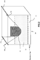
Une représentation d'un système de chauffage et de trois embarrages (E), correspondant à R'1, R'2 et R'3, est présentée
Il est bien évident qu'un second système de chauffage peut être présent sous les embarrages permettant ainsi une fusion uniforme dudit polymère sur les deux surfaces de la mèche.It is obvious that a second heating system can be present under the blockages thus allowing a uniform melting of said polymer on the two surfaces of the wick.
Le système de chauffage représenté
Les Inventeurs ont donc trouvé de manière inattendue que l'étape de chauffage telle que décrite ci-dessus effectuée après l'étape de pré-imprégnation permettait, en raison du défilement partiel ou total de ladite mèche sur la ou lesdites pièce(s) d'embarrage (E), d'obtenir une surface de contact avec ladite mèche très supérieure à une calandre et d'exercer ainsi une pression sur ladite mèche pendant un temps plus important qu'avec une calandre, ce qui a pour effet de provoquer un épanouissement de ladite mèche au niveau du ou des rouleaux.The inventors have therefore unexpectedly found that the heating step as described above carried out after the pre-impregnation step made it possible, due to the partial or total movement of said wick on the said part (s) d 'embarrage (E), to obtain a contact surface with said wick much greater than a calender and thus exert pressure on said wick for a longer time than with a calender, which has the effect of causing a development of said wick at the level of the roller (s).
Parallèlement à cela, le système de chauffage permet aussi bien le chauffage de la pièce d'embarrage (E) que de la mèche pré-imprégnée par le matériau thermoplastique, ce qui peut provoquer la fusion du polymère thermoplastique sur ladite mèche avant même son épanouissement et lorsque la mèche arrive au contact du premier embarrage (E ou R'1 sur la
Le terme « homogène » signifie que l'imprégnation est uniforme et qu'il n'y a pas de fibres sèches dans le matériau fibreux imprégné.The term "homogeneous" means that the impregnation is uniform and that there are no dry fibers in the impregnated fibrous material.
Par fibre sèche, on entend une fibre dépourvue de polymère ou pas totalement entourée de polymère.By dry fiber is meant a fiber devoid of polymer or not completely surrounded by polymer.
Par conséquent, cette étape de chauffage permet de parfaire l'imprégnation de la mèche effectuée au préalable lors de l'étape de pré-imprégnation et notamment d'obtenir une imprégnation homogène et à cœur.Consequently, this heating step makes it possible to perfect the impregnation of the wick carried out beforehand during the pre-impregnation step and in particular to obtain a homogeneous and full impregnation.
On ne sortirait pas du cadre de l'invention si la pièce d'embarrage (E) était non pas surmontée par un système de chauffage mais directement reliée à ou au contact d'un système de chauffage telle qu'une source de chaleur ou équipée d'une résistance permettant de chauffer ladite pièce d'embarrage (E).It would not be departing from the scope of the invention if the jamming part (E) was not surmounted by a heating system but directly connected to or in contact with a heating system such as a heat source or equipped. a resistor for heating said jamming part (E).
Une calandre chauffante est exclue du champ de l'invention relatif audit système de chauffage.A heating calender is excluded from the scope of the invention relating to said heating system.
Par calandre chauffante, il faut entendre un système de cylindres lisses ou crantés superposés entre lesquels la mèche pourrait circuler, lesdits cylindres exerçant une pression sur la dite mèche pour la lisser et effectuer sa mise en forme.By heating calender is meant a system of smooth or notched cylinders superimposed between which the wick could circulate, said cylinders exerting pressure on said wick in order to smooth it and effect its shaping.
Il n'y a donc pas de mise en forme de ladite mèche au niveau de ladite étape de preimprégnation et de ladite étape de chauffage, en particulier pas de contrôle précis de la largeur et de l'épaisseur du ruban à ce stade du procédé.There is therefore no shaping of said wick at said pre-impregnation step and at said heating step, in particular no precise control of the width and thickness of the tape at this stage of the process.
L'expression « en charge volontaire » signifie qu'une différence de potentiel est appliquée entre le matériau fibreux et la poudre. La charge est notamment contrôlée et amplifiée. Les grains de poudres imprègnent alors le matériau fibreux par attraction de la poudre chargée à l'opposé de la fibre. On peut charger électriquement, négativement ou positivement, la poudre par différents moyens (différence de potentiel entre deux électrodes métalliques, frottement mécanique sur parties métalliques etc...) et charger la fibre inversement (positivement ou négativement).The expression “in voluntary charge” means that a potential difference is applied between the fibrous material and the powder. The load is in particular controlled and amplified. The powder grains then impregnate the fibrous material by attraction of the charged powder opposite the fiber. The powder can be charged electrically, negatively or positively by different means (potential difference between two metal electrodes, mechanical friction on metal parts, etc.) and charge the fiber inversely (positively or negatively).
Le procédé de l'invention n'exclut pas la présence de charges électrostatiques qui pourraient apparaitre par frottement du matériau fibreux sur les éléments de l'unité de mise en oeuvre avant ou au niveau de la cuve mais qui sont en tout état de cause des charges involontaires.The method of the invention does not exclude the presence of electrostatic charges which could appear by friction of the fibrous material on the elements of the processing unit before or at the level of the tank but which are in any event of unintentional charges.
On entend par thermoplastique, ou polymère thermoplastique, un matériau généralement solide à température ambiante, pouvant être semi-cristallin ou amorphe, et qui se ramollit lors d'une augmentation de température, en particulier après passage de sa température de transition vitreuse (Tg) et s'écoule à plus haute température lorsqu'il est amorphe, ou pouvant présenter une fusion franche au passage de sa température dite de fusion (Tf) lorsqu'il est semi-cristallin, et qui redevient solide lors d'une diminution de température en dessous de sa température de cristallisation (pour un semi-cristallin) et en dessous de sa température de transition vitreuse (pour un amorphe).The term “thermoplastic” or thermoplastic polymer is understood to mean a material which is generally solid at room temperature, which may be semi-crystalline or amorphous, and which softens during an increase in temperature, in particular after passing its glass transition temperature (Tg). and flows at a higher temperature when it is amorphous, or which may present a clear melting at the passage of its so-called melting temperature (Tf) when it is semi-crystalline, and which becomes solid again when the temperature decreases below its crystallization temperature (for a semi-crystalline) and below its glass transition temperature (for an amorphous).
La Tg et la Tf sont déterminées par analyse calorimétrique différentielle (DSC) selon la norme 11357-2 :2013 et 11357-3 :2013 respectivement.The Tg and Tf are determined by differential scanning calorimetry (DSC) according to standard 11357-2: 2013 and 11357-3: 2013 respectively.
Concernant le polymère de constitution de la matrice de pré-imprégnation du matériau fibreux, c'est avantageusement un polymère thermoplastique ou un mélange de polymères thermoplastiques. Ce polymère ou mélange de polymères thermoplastiques peut être broyé sous forme de poudre, afin de pouvoir l'utiliser dans un dispositif tel qu'une cuve, en lit fluidisé.Regarding the polymer constituting the matrix for pre-impregnating the fibrous material, it is advantageously a thermoplastic polymer or a mixture of thermoplastic polymers. This polymer or mixture of thermoplastic polymers can be ground in powder form, in order to be able to use it in a device such as a tank, in a fluidized bed.
Le dispositif sous forme de cuve en lit fluidisé peut être ouvert ou fermé.The device in the form of a fluidized bed tank can be open or closed.
De manière facultative, le polymère thermoplastique ou mélange de polymères thermoplastiques comprend en outre des charges carbonées, en particulier du noir de carbone ou des nanocharges carbonées, de préférence choisies parmi des nanocharges carbonées, en particulier des graphènes et/ou des nanotubes de carbone et/ou des nanofibrilles de carbone ou leurs mélanges. Ces charges permettent de conduire l'électricité et la chaleur, et permettent par conséquent de faciliter la fusion de la matrice polymère lorsqu'elle est chauffée.Optionally, the thermoplastic polymer or mixture of thermoplastic polymers further comprises carbonaceous fillers, in particular carbon black or carbonaceous nanofillers, preferably chosen from carbonaceous nanofillers, in particular graphenes and / or carbon nanotubes and / or carbon nanofibrils or their mixtures. These charges make it possible to conduct electricity and heat, and therefore make it possible to facilitate the melting of the polymer matrix when it is heated.
Optionnellement, ledit polymère thermoplastique comprend au moins un additif, notamment choisi parmi un catalyseur, un antioxydant, un stabilisant thermique, un stabilisant UV, un stabilisant à la lumière, un lubrifiant, une charge, un plastifiant, un agent ignifugeant, un agent nucléant, un allongeur de chaîne et un colorant, un agent conducteur électrique, un agent conducteur thermique ou un mélange de ceux-ci.Optionally, said thermoplastic polymer comprises at least one additive, in particular chosen from a catalyst, an antioxidant, a thermal stabilizer, a UV stabilizer, a light stabilizer, a lubricant, a filler, a plasticizer, a flame retardant, a nucleating agent. , a chain extender and a colorant, an electrically conductive agent, a thermally conductive agent, or a mixture thereof.
Avantageusement, ledit additif est choisi parmi un agent ignifugeant, un agent conducteur électrique et un agent conducteur thermique.Advantageously, said additive is chosen from a flame retardant, an electrically conductive agent and a thermal conductor.
Selon une autre variante, le polymère thermoplastique ou mélange de polymères thermoplastiques peut en outre comprendre des polymères à cristaux liquides ou du poly(butylène téréphtalate) cyclisé, ou des mélanges en contenant, comme la résine CBT100 commercialisée par la société CYCLICS CORPORATION. Ces composés permettent notamment de fluidifier la matrice polymère à l'état fondu, pour une meilleure pénétration au cœur des fibres. Selon la nature du polymère, ou mélange de polymères thermoplastiques, utilisé pour réaliser la matrice de pré-imprégnation, notamment sa température de fusion, on choisira l'un ou l'autre de ces composés.According to another variant, the thermoplastic polymer or mixture of thermoplastic polymers can also comprise liquid crystal polymers or cyclized poly (butylene terephthalate), or mixtures containing it, such as the CBT100 resin sold by the company CYCLICS CORPORATION. These compounds make it possible in particular to fluidify the polymer matrix in the molten state, for better penetration into the heart of the fibers. Depending on the nature of the polymer, or mixture of thermoplastic polymers, used to produce the pre-impregnation matrix, in particular its melting temperature, one or the other of these compounds will be chosen.
Les polymères thermoplastiques entrant dans la constitution de la matrice de préimprégnation du matériau fibreux, peuvent être choisis parmi :
- les polymères et copolymères de la famille des polyamides (PA) aliphatiques, cycloaliphatiques ou des PA semi-aromatiques (encore dénommés polyphtalamides (PPA)),
- les polyurées, en particulier aromatiques,
- les polymères et copolymères de la famille des acryliques comme les polyacrylates, et plus particulièrement le polyméthacrylate de méthyle (PMMA) ou ses dérivés
- les polymères et copolymères de la famille des poly(aryléthercétones) (PAEK) comme le poly(étheréthercétone) (PEEK), ou les poly(aryléthercétonescétones) (PAEKK) comme le poly(éthercétonecétone) (PEKK) ou leurs dérivés,
- les polyéther-imides (PEI) aromatiques,
- les polyarylsulfures, en particulier les polyphénylène sulfures (PPS),
- les polyarylsulfones, en particulier les polyphénylène sulfones (PPSU),
- les polyoléfines, en particulier le polypropylène (PP);
- l'acide polylactique (PLA),
- l'alcool polyvinylique (PVA),
- les polymères fluorés, en particulier le poly(fluorure de vinylidène) (PVDF), ou le polytétrafluoroéthylène (PTFE) ou le polychlorotrifluoroéthylène (PCTFE),
et leurs mélanges.
- polymers and copolymers of the family of aliphatic, cycloaliphatic polyamides (PA) or semi-aromatic PAs (also called polyphthalamides (PPA)),
- polyureas, in particular aromatic,
- polymers and copolymers of the acrylic family, such as polyacrylates, and more particularly polymethyl methacrylate (PMMA) or its derivatives
- polymers and copolymers of the family of poly (aryletherketones) (PAEK) such as poly (etheretherketone) (PEEK), or poly (aryletherketonesketones) (PAEKK) such as poly (etherketonketone) (PEKK) or their derivatives,
- aromatic polyether imides (PEIs),
- polyarylsulphides, in particular polyphenylene sulphides (PPS),
- polyarylsulfones, in particular polyphenylene sulfones (PPSU),
- polyolefins, in particular polypropylene (PP);
- polylactic acid (PLA),
- polyvinyl alcohol (PVA),
- fluorinated polymers, in particular poly (vinylidene fluoride) (PVDF), or polytetrafluoroethylene (PTFE) or polychlorotrifluoroethylene (PCTFE),
and their mixtures.
Avantageusement, lorsque ledit polymère est un mélange de deux polymères P1 et P2, la proportion en poids de polymère P1 et P2 est comprise de 1-99% à 99-1%.Advantageously, when said polymer is a mixture of two polymers P1 and P2, the proportion by weight of polymer P1 and P2 is from 1-99% to 99-1%.
Avantageusement, lorsque ledit polymère thermoplastique est un mélange, et que le procédé de préimprégnation utilise une poudre sèche, ce mélange se présente sous forme d'une poudre obtenue soit par « dry blend » avant introduction dans la cuve de pré-imprégnation ou par « dry blend » réalisé directement dans la cuve ou encore, par broyage d'un compound réalisé au préalable en extrudeuse.Advantageously, when said thermoplastic polymer is a mixture, and when the pre-impregnation process uses a dry powder, this mixture is in the form of a powder obtained either by “dry blend” before introduction into the pre-impregnation tank or by “ dry blend ”produced directly in the tank or even by grinding a compound previously produced in an extruder.
Avantageusement, ce mélange est composé d'une poudre obtenue par « dry blend », avant l'introduction dans la cuve ou directement dans la cuve, et ce mélange de deux polymères P1 et P2 est un mélange de PEKK et de PEI.Advantageously, this mixture is composed of a powder obtained by “dry blend”, before introduction into the tank or directly into the tank, and this mixture of two polymers P1 and P2 is a mixture of PEKK and PEI.
Avantageusement, le mélange PEKK/PEI est compris de 90-10% à 60-40% en poids, en particulier de 90-10% à 70-30% en poids.Advantageously, the PEKK / PEI mixture is comprised from 90-10% to 60-40% by weight, in particular from 90-10% to 70-30% by weight.
Le polymère thermoplastique peut correspondre au polymère final non réactif qui imprégnera le matériau fibreux ou à un prépolymère réactif, qui imprégnera également le matériau fibreux, mais est susceptible de réagir sur lui-même ou avec un autre prépolymère, en fonction des fins de chaîne portées par ledit prépolymère, après pré-imprégnation, ou encore avec un allongeur de chaîne et notamment lors d'un chauffage au niveau d'une calandre chauffante.The thermoplastic polymer can correspond to the final unreactive polymer which will impregnate the fibrous material or to a reactive prepolymer which will also impregnate the fibrous material, but is capable of reacting on itself or with another prepolymer, depending on the chain ends worn by said prepolymer, after pre-impregnation, or alternatively with a chain extender and in particular during heating at a heating calender.
L'expression « polymère non réactif » signifie que le poids moléculaire n'est plus susceptible d'évoluer significativement, c'est-à-dire que sa masse moléculaire en nombre (Mn) évolue de moins de 50% lors de sa mise en oeuvre et correspond donc au polymère polyamide final de la matrice thermoplastique.The expression “non-reactive polymer” means that the molecular weight is no longer likely to change significantly, that is to say that its molecular weight in number (Mn) changes by less than 50% when it is put into use. works and therefore corresponds to the final polyamide polymer of the thermoplastic matrix.
A l'opposé, l'expression « polymère réactif » signifie que le poids moléculaire dudit polymère réactif va évoluer durant la mise en oeuvre par réaction de prépolymères réactifs entre eux par condensation, substitution ou avec un allongeur de chaîne par polyaddition et sans élimination de sous-produits volatils pour conduire au polymère polyamide final (non réactif) de la matrice thermoplastique.In contrast, the expression “reactive polymer” means that the molecular weight of said reactive polymer will change during use by reacting reactive prepolymers with one another by condensation, substitution or with a chain extender by polyaddition and without elimination of volatile by-products to lead to the final (non-reactive) polyamide polymer from the thermoplastic matrix.
Selon une première possibilité, ledit prépolymère peut comprendre ou être constituée de, au moins un prépolymère (polyamide) réactif porteur sur la même chaîne (c'est-à-dire sur le même prépolymère), de deux fonctions terminales X' et Y' fonctions respectivement coréactives entre elles par condensation, plus particulièrement avec X' et Y' étant amine et carboxy ou carboxy et amine respectivement. Selon une deuxième possibilité, ledit prépolymère peut comprendre ou être constituée de, au moins deux prépolymères polyamides réactifs entre eux et porteurs chacun respectivement de deux fonctions terminales X' ou Y', identiques (identiques pour même prépolymère et différentes entre les deux prépolymères), ladite fonction X' d'un prépolymère pouvant réagir seulement avec ladite fonction Y' de l'autre prépolymère, en particulier par condensation, plus particulièrement avec X' et Y' étant amine et carboxy ou carboxy et amine respectivement. Selon une troisième possibilité, ledit prépolymère peut comprendre ou être constituée de, au moins un prépolymère dudit polymère polyamide thermoplastique, porteur de n fonctions réactives terminales X, choisies parmi : -NH2, -CO2H et -OH, de préférence NH2 et -CO2H avec n étant 1 à 3, de préférence de 1 à 2, plus préférentiellement 1 ou 2, plus particulièrement 2 et au moins un allongeur de chaîne Y-A'-Y, avec A' étant un biradical hydrocarboné, porteur de 2 fonctions réactives terminales Y identiques, réactives par polyaddition avec au moins une fonction X dudit prépolymère a1), de préférence de masse moléculaire inférieure à 500, plus préférentiellement inférieure à 400.According to a first possibility, said prepolymer may comprise or consist of at least one reactive prepolymer (polyamide) carrying on the same chain (that is to say on the same prepolymer), of two terminal functions X 'and Y' functions respectively coreactive with each other by condensation, more particularly with X 'and Y' being amine and carboxy or carboxy and amine respectively. According to a second possibility, said prepolymer may comprise or consist of at least two polyamide prepolymers which are reactive with each other and each bear respectively two identical terminal functions X 'or Y' (identical for the same prepolymer and different between the two prepolymers), said X 'function of a prepolymer being able to react only with said Y' function of the other prepolymer, in particular by condensation, more particularly with X 'and Y' being amine and carboxy or carboxy and amine respectively. According to a third possibility, said prepolymer can comprise or consist of at least one prepolymer of said thermoplastic polyamide polymer, carrying n terminal reactive functions X, chosen from: -NH2, -CO2H and -OH, preferably NH2 and -CO2H with n being 1 to 3, preferably 1 to 2, more preferably 1 or 2, more particularly 2 and at least one Y-A'-Y chain extender, with A 'being a hydrocarbon-based biradical, carrying 2 terminal reactive functions Identical Y, reactive by polyaddition with at least one X function of said prepolymer a1), preferably of molecular mass less than 500, more preferably less than 400.
La masse moléculaire moyenne en nombre Mn dudit polymère final de la matrice thermoplastique est de préférence dans une plage allant de 10000 à 40000, de préférence de 12000 à 30000. Ces valeurs Mn peuvent correspondre à des viscosités inhérentes supérieures ou égales à 0,8 telle que déterminées dans le m-crésol selon la norme ISO 307:2007 mais en changeant le solvant (utilisation du m-crésol à la place de l'acide sulfurique et la température étant de 20°C).The number-average molecular weight Mn of said final polymer of the thermoplastic matrix is preferably in a range from 10,000 to 40,000, preferably from 12,000 to 30,000. These Mn values may correspond to inherent viscosities greater than or equal to 0.8 such than determined in m-cresol according to standard ISO 307: 2007 but by changing the solvent (use of m-cresol in place of sulfuric acid and the temperature being 20 ° C).
Lesdits prépolymères réactifs selon les deux options citées plus haut, ont une masse moléculaire moyenne en nombre Mn allant de 500 à 10000, de préférence de 1000 à 6000, en particulier de 2500 à 6000.Said reactive prepolymers according to the two options mentioned above have a number-average molecular weight Mn ranging from 500 to 10,000, preferably from 1000 to 6000, in particular from 2500 to 6000.
Les Mn sont déterminées en particulier par le calcul à partir du taux des fonctions terminales déterminé par titration potentiométrique en solution et la fonctionnalité desdits prépolymères. Les masses Mn peuvent également être déterminées par chromatographie d'exclusion stérique ou par RMN.The Mn are determined in particular by calculation from the level of terminal functions determined by potentiometric titration in solution and the functionality of said prepolymers. The Mn masses can also be determined by size exclusion chromatography or by NMR.
La nomenclature utilisée pour définir les polyamides est décrite dans la norme ISO 1874-1:2011 "Plastiques - Matériaux polyamides (PA) pour moulage et extrusion - Partie 1 : Désignation", notamment en page 3 (tableaux 1 et 2) et est bien connue de l'homme du métier.The nomenclature used to define polyamides is described in standard ISO 1874-1: 2011 "Plastics - Polyamide (PA) materials for molding and extrusion - Part 1: Designation ", in particular on page 3 (Tables 1 and 2) and is well known to those skilled in the art.
Le polyamide peut être un homopolyamide ou un copolyamide ou un mélange de ceux-ci. Avantageusement, les prépolymères de constitution de la matrice sont choisis parmi les Polyamides (PA), en particulier choisis parmi les polyamides aliphatiques, les polyamides cycloaliphatiques, et les polyamides semi-aromatiques (polyphthalamides) éventuellement modifiés par des motifs urées, et leur copolymères, le Polyméthacrylate de méthyle (PPMA) et ses copolymères, les Polyether imides (PEI), le Poly(sulfure de phénylène) (PPS), le Poly(sulfone de phénylène) (PPSU), le PVDF, le Poly(éthercétonecétone) (PEKK), le Poly(étheréthercétone) (PEEK), les polymères fluorés comme le poly(fluorure de vinylidène) (PVDF).The polyamide can be a homopolyamide or a copolyamide or a mixture thereof. Advantageously, the prepolymers constituting the matrix are chosen from polyamides (PA), in particular chosen from aliphatic polyamides, cycloaliphatic polyamides, and semi-aromatic polyamides (polyphthalamides) optionally modified with urea units, and their copolymers, Polymethyl methacrylate (PPMA) and its copolymers, Polyether imides (PEI), Poly (phenylene sulfide) (PPS), Poly (phenylene sulfone) (PPSU), PVDF, Poly (etherketonecetone) (PEKK) ), Poly (etheretherketone) (PEEK), fluoropolymers such as poly (vinylidene fluoride) (PVDF).
Pour les polymères fluorés, on peut utiliser un homopolymère du fluorure de vinylidène (VDF de formule CH2=CF2) ou un copolymère du VDF comprenant en poids au moins 50% en masse de VDF et au moins un autre monomère copolymérisable avec le VDF. La teneur en VDF doit être supérieure à 80% en masse, voire mieux 90% en masse, pour assurer une bonne résistance mécanique et chimique à la pièce de structure, surtout lorsqu'elle est soumise à des contraintes thermiques et chimiques. Le comonomère peut être un monomère fluoré tel que par exemple le fluorure de vinyle.For the fluorinated polymers, it is possible to use a homopolymer of vinylidene fluoride (VDF of formula CH 2 = CF 2 ) or a copolymer of VDF comprising at least 50% by weight of VDF and at least one other monomer which can be copolymerized with VDF. . The VDF content must be greater than 80% by mass, or even better 90% by mass, to ensure good mechanical and chemical resistance to the structural part, especially when it is subjected to thermal and chemical stresses. The comonomer can be a fluorinated monomer such as, for example, vinyl fluoride.
Pour des pièces de structure devant résister à des températures élevées, outre les polymères fluorés, on utilise avantageusement selon l'invention les PAEK (PolyArylEtherKetone) tels que les poly(éther cétones) PEK, le poly(éther éther cétone) PEEK, le poly(éther cétone cétone) PEKK, le Poly(éther cétone éther cétone cétone) PEKEKK ou les PA de haute température de transition vitreuse Tg).For structural parts that have to withstand high temperatures, in addition to fluoropolymers, PAEK (PolyArylEtherKetone) such as poly (ether ketones) PEK, poly (ether ether ketone) PEEK, poly (ether ketone ketone) PEKK, Poly (ether ketone ether ketone ketone) PEKEKK or PAs of high glass transition temperature Tg).
Avantageusement, ledit polymère thermoplastique est un polymère dont la température de transition vitreuse est telle que Tg ≥ 80°C, notamment ≥ 100°C, en particulier ≥ 120°C, notamment ≥ 140°C, ou un polymère semi-cristallin dont la température de fusion Tf ≥ 150°C. Avantageusement, ledit au moins un prépolymère thermoplastique est sélectionné parmi les polyamides, le PEKK, le PEI et un mélange PEKK et de PEI.Advantageously, said thermoplastic polymer is a polymer whose glass transition temperature is such that Tg ≥ 80 ° C, in particular ≥ 100 ° C, in particular ≥ 120 ° C, in particular ≥ 140 ° C, or a semi-crystalline polymer whose melting temperature Tf ≥ 150 ° C. Advantageously, said at least one thermoplastic prepolymer is selected from polyamides, PEKK, PEI and a mixture of PEKK and PEI.
Avantageusement, ledit polyamide est choisi parmi les polyamides aliphatiques, les polyamides cycloaliphatiques et les polyamides semi-aromatiques (polyphthalamides). Avantageusement, ledit prépolymère polyamide aliphatique est choisi parmi :
- le polyamide 6 (PA-6), le polyamide 11 (PA-11), le polyamide 12 (PA-12), le polyamide 66 (PA-66), le polyamide 46 (PA-46), le polyamide 610 (PA-610), le polyamide 612 (PA-612), le polyamide 1010 (PA-1010), le polyamide 1012 (PA-1012), le polyamide 11/1010 et le polyamide 12/1010, ou un mélange de ceux-ci ou un copolyamide de ceux-ci, et les copolymères blocs, notamment polyamide/polyéther (PEBA), et ledit polyamide semi-aromatique est un polyamide semi-aromatique, éventuellement modifié par des unités urées, notamment un PA MXD6 et un PA MXD10 ou un polyamide semi-aromatique de formule X/YAr, tel que décrits dans
EP1505099
X.T désigne un motif obtenu à partir de la polycondensation d'une diamine en Cx et de l'acide téréphtalique, avec x représentant le nombre d'atomes de carbone de la diamine en Cx, x étant compris entre 6 et 36, avantageusement entre 9 et 18,notamment un polyamide de formule A/6T, A/9T, A/10T ou A/11T, A étant tel que défini ci-dessus, en particulier un polyamide PA 6/6T, un PA 66/6T, un PA 6I/6T, un PA MPMDT/6T, un PA PA11/10T,un PA 11/6T/10T, un PA MXDT/10T, un PA MPMDT/10T, un PA BACT/10T, un PA BACT/6T, PA BACT/10T/6T.
- polyamide 6 (PA-6), polyamide 11 (PA-11), polyamide 12 (PA-12), polyamide 66 (PA-66), polyamide 46 (PA-46), polyamide 610 (PA -610), polyamide 612 (PA-612), polyamide 1010 (PA-1010), polyamide 1012 (PA-1012),
polyamide 11/1010 andpolyamide 12/1010, or a mixture thereof or a copolyamide thereof, and block copolymers, in particular polyamide / polyether (PEBA), and said semi-aromatic polyamide is a semi-aromatic polyamide, optionally modified with urea units, in particular a PA MXD6 and a PA MXD10 or a semi-aromatic polyamide of formula X / YAr, as described inEP1505099
XT denotes a unit obtained from the polycondensation of a Cx diamine and terephthalic acid, with x representing the number of carbon atoms of the Cx diamine, x being between 6 and 36, advantageously between 9 and 18, in particular a polyamide of formula A / 6T, A / 9T, A / 10T or A / 11T, A being as defined above, in particular a polyamide PA 6 / 6T, a PA 66 / 6T, a PA 6I / 6T, one PA MPMDT / 6T, one PA PA11 / 10T, onePA 11 / 6T / 10T, one PA MXDT / 10T, one PA MPMDT / 10T, one PA BACT / 10T, one PA BACT / 6T, PA BACT / 10T / 6T.
T correspond à l'acide téréphtalique, MXD correspond à la m-xylylène diamine, MPMD correspond à la méthylpentaméthylène diamine et BAC correspond au bis(aminométhyl)cyclohexane.T corresponds to terephthalic acid, MXD corresponds to m-xylylenediamine, MPMD corresponds to methylpentamethylene diamine and BAC corresponds to bis (aminomethyl) cyclohexane.
Concernant les fibres de constitution dudit matériau fibreux, ce sont notamment des fibres d'origine minérale, organique ou végétale. Parmi les fibres d'origine minérale, on peut citer les fibres de carbone, les fibres de verre, les fibres de basalte, les fibres de silice, ou les fibres de carbure de silicium par exemple. Parmi les fibres d'origine organique, on peut citer les fibres à base de polymère thermoplastique ou thermodurcissable, telles que des fibres de polyamides semi-aromatiques, des fibres d'aramide ou des fibres en polyoléfines par exemple. De préférence, elles sont à base de polymère thermoplastique amorphe et présentent une température de transition vitreuse Tg supérieure à la Tg du polymère ou mélange de polymère thermoplastique de constitution de la matrice de pré-imprégnation lorsque ce dernier est amorphe, ou supérieure à la Tf du polymère ou mélange de polymère thermoplastique de constitution de la matrice de pré-imprégnation lorsque ce dernier est semi-cristallin. Avantageusement, elles sont à base de polymère thermoplastique semi-cristallin et présentent une température de fusion Tf supérieure à la Tg du polymère ou mélange de polymère thermoplastique de constitution de la matrice de pré-imprégnation lorsque ce dernier est amorphe, ou supérieure à la Tf du polymère ou mélange de polymère thermoplastique de constitution de la matrice de pré-imprégnation lorsque ce dernier est semi-cristallin. Ainsi, il n'y a aucun risque de fusion pour les fibres organiques de constitution du matériau fibreux lors de l'imprégnation par la matrice thermoplastique du composite final. Parmi les fibres d'origine végétale, on peut citer les fibres naturelles à base de lin, de chanvre, de lignine, de bambou, de soie notamment d'araignée, de sisal, et d'autres fibres cellulosiques, en particulier de viscose. Ces fibres d'origine végétale peuvent être utilisées pures, traitées ou bien enduites d'une couche d'enduction, en vue de faciliter l'adhérence et l'imprégnation de la matrice de polymère thermoplastique.As regards the fibers constituting said fibrous material, they are in particular fibers of mineral, organic or plant origin. Among the fibers of mineral origin, mention may be made of carbon fibers, glass fibers, basalt fibers, silica fibers, or silicon carbide fibers, for example. Among the fibers of organic origin, mention may be made of fibers based on a thermoplastic or thermosetting polymer, such as semi-aromatic polyamide fibers, aramid fibers or polyolefin fibers, for example. Preferably, they are based on an amorphous thermoplastic polymer and have a glass transition temperature Tg greater than the Tg of the polymer or mixture of thermoplastic polymer constituting the pre-impregnation matrix when the latter is amorphous, or greater than the Tm of the polymer or mixture of thermoplastic polymer constituting the prepreg matrix when the latter is semi-crystalline. Advantageously, they are based on a semi-crystalline thermoplastic polymer and have a melting point Tm greater than the Tg of the polymer or mixture of thermoplastic polymer constituting the prepreg matrix when the latter is amorphous, or greater than the Tm. polymer or polymer blend thermoplastic constituting the pre-impregnation matrix when the latter is semi-crystalline. Thus, there is no risk of fusion for the organic fibers constituting the fibrous material during impregnation with the thermoplastic matrix of the final composite. Among the fibers of plant origin, mention may be made of natural fibers based on flax, hemp, lignin, bamboo, silk, especially spider silk, sisal, and other cellulose fibers, in particular viscose. These fibers of plant origin can be used pure, treated or else coated with a coating layer, with a view to facilitating the adhesion and impregnation of the thermoplastic polymer matrix.
Le matériau fibreux peut également être un tissu, tressé ou tissé avec des fibres.The fibrous material can also be a fabric, braided or woven with fibers.
Il peut également correspondre à des fibres avec des fils de maintien.It can also correspond to fibers with retaining threads.
Ces fibres de constitution peuvent être utilisées seules ou en mélanges. Ainsi, des fibres organiques peuvent être mélangées aux fibres minérales pour être pré-imprégnée de polymère thermoplastique et former le matériau fibreux pré-imprégné.These constitution fibers can be used alone or in mixtures. Thus, organic fibers can be mixed with mineral fibers to be prepreg with thermoplastic polymer and form the prepreg fibrous material.
Les mèches de fibres organiques peuvent avoir plusieurs grammages. Elles peuvent en outre présenter plusieurs géométries. Les fibres peuvent se présenter sous forme de fibres coupées, qui composent alors les feutres ou les mats pouvant se présenter sous la forme de bandes, nappes, ou morceaux, ou sous forme de fibres continues, qui composent les tissus 2D, les non-tissés (NCF), les tresses ou mèches de fibres unidirectionnelles (UD) ou non tissées. Les fibres de constitution du matériau fibreux peuvent en outre se présenter sous forme d'un mélange de ces fibres de renfort de différentes géométries. De préférence, les fibres sont continues.The rovings of organic fibers can have several grammages. They can also have several geometries. The fibers can be in the form of staple fibers, which then make up the felts or mats which can be in the form of strips, sheets, or pieces, or in the form of continuous fibers, which make up 2D fabrics, nonwovens (NCF), braids or rovings of unidirectional (UD) or non-woven fibers. The fibers constituting the fibrous material may also be in the form of a mixture of these reinforcing fibers of different geometries. Preferably, the fibers are continuous.
De préférence le matériau fibreux est constitué par des fibres continues de carbone, de verre ou de carbure de silicium ou leur mélange, en particulier des fibres de carbone. Il est utilisé sous forme d'une mèche ou de plusieurs mèches.Preferably, the fibrous material consists of continuous fibers of carbon, glass or silicon carbide or their mixture, in particular carbon fibers. It is used in the form of a wick or several wicks.
Dans les matériaux imprégnés aussi appelés « prêts à l'emploi », le polymère ou mélange de polymères thermoplastiques d'imprégnation est réparti uniformément et de manière homogène autour des fibres. Dans ce type de matériau, le polymère thermoplastique d'imprégnation doit être réparti de manière la plus homogène possible au sein des fibres afin d'obtenir un minimum de porosités, c'est à dire un minimum de vides entre les fibres. En effet, la présence de porosités dans ce type de matériaux peut agir comme des points de concentrations de contraintes, lors d'une mise sous contrainte mécanique de traction par exemple, et qui forment alors des points d'initiation de rupture du matériau fibreux imprégné et le fragilisent mécaniquement. Une répartition homogène du polymère ou mélange de polymères améliore donc la tenue mécanique et l'homogénéité du matériau composite formé à partir de ces matériaux fibreux imprégnés.In the impregnated materials also called “ready to use”, the polymer or mixture of thermoplastic polymers for impregnation is distributed uniformly and homogeneously around the fibers. In this type of material, the thermoplastic impregnation polymer must be distributed as homogeneously as possible within the fibers in order to obtain a minimum of porosities, that is to say a minimum of voids between the fibers. In fact, the presence of porosities in this type of material can act as points of stress concentrations, during mechanical tensile stress for example, and which then form points of initiation of rupture of the impregnated fibrous material. and weaken it mechanically. A homogeneous distribution of the polymer or mixture of polymers therefore improves the mechanical strength and the homogeneity of the composite material formed from these impregnated fibrous materials.
Ainsi, dans le cas de matériaux imprégnés dits « prêts à l'emploi », le taux de fibres dans ledit matériau fibreux pré-imprégné est compris de 45 à 65 % en volume, de préférence de 50 à 60% en volume, notamment de 54 à 60% en volume.Thus, in the case of so-called “ready-to-use” impregnated materials, the proportion of fibers in said prepreg fibrous material is between 45% to 65% by volume, preferably from 50 to 60% by volume, in particular of 54 to 60% by volume.
La mesure du taux d'imprégnation peut être réalisée par analyse d'image (utilisation de microscope ou d'appareil photo ou de caméra numérique, notamment), d'une coupe transversale du ruban, en divisant la surface du ruban imprégné par le polymère par la surface totale du produit (surface imprégnée plus surface des porosités). Afin d'obtenir une image de bonne qualité il est préférable d'enrober le ruban découpé dans son sens transversal dans une résine de polissage standard et de polir avec un protocole standard permettant l'observation de l'échantillon au microscope grossissement fois 6 au minimum. Le taux de porosité dudit matériau fibreux imprégné est inférieur à 10%, notamment inférieur à 5%, en particulier inférieur à 2%.The measurement of the rate of impregnation can be carried out by image analysis (use of a microscope or of a camera or digital camera, in particular), of a cross section of the tape, by dividing the surface of the tape impregnated with the polymer by the total surface of the product (impregnated surface plus porosity surface). In order to obtain a good quality image, it is preferable to coat the ribbon cut in its transverse direction in a standard polishing resin and to polish with a standard protocol allowing the observation of the sample under a microscope magnification times 6 at least. . The level of porosity of said impregnated fibrous material is less than 10%, in particular less than 5%, in particular less than 2%.
Il faut noter qu'un taux de porosité nul est difficilement accessible et que par conséquent, avantageusement le taux de porosité est supérieur à 0% mais inférieur aux taux cités ci-dessus.It should be noted that a zero porosity level is difficult to access and that consequently, advantageously the porosity level is greater than 0% but less than the rates mentioned above.
Le taux de porosité correspond au taux de porosité fermée et peut être déterminée soit par microscopie électronique, soit comme étant l'écart relatif entre la densité théorique et la densité expérimentale dudit matériau fibreux imprégné tel que décrit dans la partie exemples de la présente invention.The rate of porosity corresponds to the rate of closed porosity and can be determined either by electron microscopy or as being the relative difference between the theoretical density and the experimental density of said impregnated fibrous material as described in the examples part of the present invention.
L'étape de pré-imprégnation comme déjà indiquée ci-dessus peut être effectuée selon les techniques bien connues de l'homme du métier et notamment choisies parmi celles décrites ci-dessus.The pre-impregnation step as already indicated above can be carried out according to techniques well known to those skilled in the art and in particular chosen from those described above.
Dans un mode de réalisation avantageux, l'étape de pré-imprégnation est effectuée avec un système en lit fluidisé, notamment à grande vitesse.In an advantageous embodiment, the pre-impregnation step is carried out with a fluidized bed system, in particular at high speed.
Avantageusement, la pré-imprégnation est effectuée avec un système en lit fluidisé, notamment à grande vitesse, et une ou plusieurs pièce(s) d'embarrage(s) (E") est(sont) présente(s) en amont dudit système.Advantageously, the pre-impregnation is carried out with a fluidized bed system, in particular at high speed, and one or more jamming part (s) (E ") is (are) present upstream of said system .
Il faut noter que les pièces d'embarrage (E) et (E") peuvent être identiques ou différentes que ce soit au niveau du matériau ou de la forme et ses caractéristiques (diamètre, longueur, largeur, hauteur ... en fonction de la forme).It should be noted that the jamming parts (E) and (E ") may be identical or different whether in terms of material or shape and its characteristics (diameter, length, width, height ... depending on the form).
Avantageusement, l'étape de pré-imprégnation est effectuée en lit fluidisé.Advantageously, the pre-impregnation step is carried out in a fluidized bed.
Un exemple d'unité de mise en oeuvre d'un procédé de fabrication sans l'étape de chauffage au moyen d'au moins une pièce d'embarrage est décrit dans la demande internationale
Ce système décrit l'utilisation d'une cuve comprenant un lit fluidisé pour effectuer l'étape de pré-imprégnation et peut être utilisé dans le cadre de l'invention.This system describes the use of a tank comprising a fluidized bed to carry out the prepreg step and can be used within the framework of the invention.
Avantageusement, la cuve comprenant le lit fluidisé est munie d'au moins une pièce d'embarrage (E') (
Il faut noter que les pièces d'embarrage (E) et (E') peuvent être identiques ou différentes que ce soit au niveau du matériau ou de la forme et ses caractéristiques (diamètre, longueur, largeur, hauteur ... en fonction de la forme).It should be noted that the jamming parts (E) and (E ') can be identical or different, whether in terms of material or shape and its characteristics (diameter, length, width, height, etc., depending on the form).
Cependant, la pièce d'embarrage (E') n'est ni chauffante ni chauffée.However, the embedding part (E ') is neither heating nor heated.
L'étape de pré-imprégnation du matériau fibreux est réalisée par passage d'une ou plusieurs mèches dans un dispositif de pré-imprégnation en continu, comprenant une cuve (10) muni d'au moins une pièce d'embarrage (E') et comprenant un lit fluidisé (12) de poudre de ladite matrice polymère.The step of pre-impregnating the fibrous material is carried out by passing one or more wicks through a continuous pre-impregnation device, comprising a tank (10) provided with at least one jamming part (E ') and comprising a fluidized bed (12) of powder of said polymer matrix.
La poudre de ladite matrice polymère ou polymère est mise en suspension dans un gaz G (de l'air par exemple) introduit dans la cuve et circulant dans la cuve (10) à travers une trémie (11). La ou les mèches sont mises en circulation dans ce lit fluidisé (12).The powder of said polymer or polymer matrix is suspended in a gas G (air for example) introduced into the tank and circulating in the tank (10) through a hopper (11). The wick (s) are circulated in this fluidized bed (12).
La cuve peut avoir toute forme, notamment cylindrique ou parallélépipédique, en particulier un parallélépipède rectangle ou un cube, avantageusement un parallélépipède rectangle. La cuve (10) peut être une cuve ouverte ou fermée. Avantageusement, elle est ouverte. Dans le cas où la cuve est fermée, elle est alors équipée d'un système d'étanchéité pour que la poudre de ladite matrice polymère ne puisse pas sortir de ladite cuve.The tank may have any shape, in particular cylindrical or parallelepiped, in particular a rectangular parallelepiped or a cube, advantageously a rectangular parallelepiped. The tank (10) can be an open or a closed tank. Advantageously, it is open. In the case where the tank is closed, it is then equipped with a sealing system so that the powder of said polymer matrix cannot come out of said tank.
Cette étape de pré-imprégnation est donc effectuée par voie sèche, c'est à dire que la matrice polymère thermoplastique est sous forme de poudre, notamment en suspension dans un gaz, en particulier de l'air, mais ne peut pas être en dispersion dans un solvant ou dans l'eau. Chaque mèche à pré-imprégner est déroulée d'un dispositif à dévidoirs sous la traction engendrée par des cylindres (non représentés). De préférence, le dispositif à dévidoirs comprend une pluralité de dévidoirs, chaque dévidoir permettant de dérouler une mèche à pré-imprégner. Ainsi, il est possible de pré-imprégner plusieurs mèches de fibres simultanément. Chaque dévidoir est pourvu d'un frein (non représenté) de manière à appliquer une tension sur chaque mèche de fibres. Dans ce cas, un module d'alignement permet de disposer les mèches de fibres parallèlement les unes par rapport aux autres. De cette manière les mèches de fibres ne peuvent pas être en contact les unes avec les autres, ce qui permet d'éviter une dégradation mécanique des fibres par frottement entre elles.This pre-impregnation step is therefore carried out by the dry route, that is to say that the thermoplastic polymer matrix is in the form of a powder, in particular in suspension in a gas, in particular air, but cannot be in dispersion. in a solvent or in water. Each wick to be pre-impregnated is unwound from a reel device under the traction generated by the cylinders (not shown). Preferably, the reel device comprises a plurality of reels, each reel enabling a wick to be pre-impregnated to be unwound. Thus, it is possible to pre-impregnate several strands of fibers simultaneously. Each reel is provided with a brake (not shown) so as to apply tension to each strand of fibers. In this case, an alignment module makes it possible to arrange the strands of fibers parallel to one another. In this way, the strands of fibers cannot be in contact with each other, which makes it possible to avoid mechanical degradation of the fibers by friction between them.
La mèche de fibres ou les mèches de fibres parallèles passent alors dans une cuve (10), comprenant en particulier un lit fluidisé (12), munie d'une pièce d'embarrage (E') qui est un rouleau de compression (24) dans le cas de la
L'expression « temps de séjour dans la poudre» signifie le temps durant lequel la mèche est en contact avec ladite poudre dans le lit fluidisé.The expression “residence time in the powder” means the time during which the wick is in contact with said powder in the fluidized bed.
Le procédé selon l'invention comprend donc un premier épanouissement lors de l'étape de pré-imprégnation.The method according to the invention therefore comprises a first expansion during the prepregnation step.
L'utilisation d'au moins un embarrage (E') dans l'étape de pré-imprégnation permet donc une pré-imprégnation améliorée par rapport aux procédés de l'art antérieur.The use of at least one embedment (E ') in the prepreg step therefore allows improved prepreg compared to the methods of the prior art.
Par pièce d'embarrage (E'), il faut entendre tout système sur lequel la mèche a la possibilité de défiler dans la cuve. La pièce d'embarrage (E') peut avoir n'importe quelle forme à partir du moment où la mèche peut défiler dessus.The term “jamming part” (E ') should be understood to mean any system on which the bit has the possibility of scrolling in the tank. The embedding part (E ') can have any shape from the moment when the bit can scroll above.
Un exemple de pièce d'embarrage (E'), sans restreindre l'invention à celui-ci, est détaillé dans la
Cette pré-imprégnation est réalisée afin de permettre à la poudre de ladite matrice polymère de pénétrer dans la mèche de fibre et d'adhérer aux fibres suffisamment pour supporter le transport de la mèche poudrée hors de la cuve.This pre-impregnation is carried out in order to allow the powder of said polymer matrix to penetrate into the fiber strand and to adhere to the fibers sufficiently to support the transport of the powdered strand out of the tank.
Si le matériau fibreux, tel que les mèches de fibres de verre ou de carbone, présente un ensimage, une étape optionnelle de dé-ensimage peut être effectuée avant le passage du matériau fibreux dans la cuve. Le terme« ensimage » désigne les traitements de surface appliqués aux fibres de renfort en sortie de filière (ensimage textile) et sur les tissus (ensimage plastique).If the fibrous material, such as the strands of glass or carbon fibers, has a size, an optional de-size step can be carried out before the fibrous material passes through the tank. The term “sizing” designates the surface treatments applied to the reinforcing fibers at the outlet of the die (textile sizing) and to the fabrics (plastic sizing).
L'ensimage "textile" appliqué sur les fibres, en sortie de filière consiste à déposer un agent de liaison assurant la cohésion des fibres entre elles, diminuant l'abrasion et facilitant les manipulations ultérieures (tissage, drapage, tricotage) et évitant la formation de charges électrostatiques.The "textile" sizing applied to the fibers, at the outlet of the die, consists in depositing a binding agent ensuring the cohesion of the fibers between them, reducing abrasion and facilitating subsequent handling (weaving, draping, knitting) and avoiding formation electrostatic charges.
L'ensimage "plastique" ou "finish" appliqué sur les tissus consiste à déposer un agent de pontage dont les rôles sont d'assurer une liaison physico-chimique entre les fibres et la résine et de protéger la fibre de son environnement.The "plastic" or "finish" sizing applied to fabrics consists in depositing a bridging agent whose roles are to ensure a physicochemical bond between the fibers and the resin and to protect the fiber from its environment.
Avantageusement, l'étape de pré-imprégnation est effectuée en lit fluidisé avec contrôle du temps de séjour dans la poudre est compris de 0,01 s à 10s, préférentiellement de 0,1 s à 5s, et en particulier de 0,1s à 3s.Advantageously, the pre-impregnation step is carried out in a fluidized bed with control of the residence time in the powder being from 0.01 s to 10 s, preferably from 0.1 s to 5 s, and in particular from 0.1 s to 3s.
Le temps de séjour du matériau fibreux dans la poudre est essentiel à la pré-imprégnation dudit matériau fibreux.The residence time of the fibrous material in the powder is essential for the prepregnation of said fibrous material.
En deçà de 0,1s, la pré-imprégnation n'est pas bonne.Below 0.1 s, the pre-impregnation is not good.
Au-delà de 10s, le taux de matrice polymère pré-imprégnant le matériau fibreux est trop important et les propriétés mécaniques du matériau fibreux pré-imprégné seront mauvaises. Avantageusement, la cuve utilisée dans le procédé de l'invention comprend un lit fluidisé et ladite étape de pré-imprégnation est effectuée avec un épanouissement simultané de ladite mèche ou desdites mèches entre l'entrée et la sortie de la cuve comprenant ledit lit fluidisé. L'expression « entrée de la cuve » correspond à la tangente verticale du bord de la cuve qui comprend le lit fluidisé.Beyond 10 s, the rate of polymer matrix pre-impregnating the fibrous material is too high and the mechanical properties of the pre-impregnated fibrous material will be poor. Advantageously, the tank used in the process of the invention comprises a fluidized bed and said pre-impregnation step is carried out with simultaneous expansion of said wick or said wicks between the inlet and the outlet of the tank comprising said fluidized bed. The expression “inlet of the vessel” corresponds to the vertical tangent of the edge of the vessel which comprises the fluidized bed.
L'expression « sortie de la cuve » correspond à la tangente verticale de l'autre bord de la cuve qui comprend le lit fluidisé.The expression “outlet of the tank” corresponds to the vertical tangent of the other edge of the tank which includes the fluidized bed.
En fonction de la géométrie de la cuve, la distance entre l'entrée et la sortie de celle-ci correspond donc au diamètre dans le cas d'une cuve cylindrique, au côté dans le cas d'une cuve cubique ou à la largeur ou la longueur dans le cas d'une cuve parallélépipèdique rectangle. L'épanouissement consiste à singulariser au maximum chaque fibre constituant ladite mèche des autres fibres qui l'entourent dans son plus proche espace. Il correspond à l'étalement transverse de la mèche.Depending on the geometry of the tank, the distance between the inlet and the outlet thereof therefore corresponds to the diameter in the case of a cylindrical tank, to the side in the case of a cubic tank or to the width or the length in the case of a rectangular parallelepiped tank. The development consists in singling out as much as possible each fiber constituting said wick from the other fibers which surround it in its closest space. It corresponds to the transverse spread of the wick.
En d'autres termes, l'étalement transverse ou la largeur de la mèche augmente entre l'entrée du lit fluidisé (ou de la cuve comprenant le lit fluidisé) et la sortie du lit fluidisé (ou de la cuve comprenant le lit fluidisé) et permet ainsi une pré-imprégnation améliorée du matériau fibreux.In other words, the transverse spread or the width of the wick increases between the inlet of the fluidized bed (or of the vessel comprising the fluidized bed) and the outlet of the fluidized bed (or of the vessel comprising the fluidized bed). and thus allows improved prepregnation of the fibrous material.
Le lit fluidisé peut être ouvert ou fermé, en particulier il est ouvert.The fluidized bed can be open or closed, in particular it is open.
Avantageusement, le lit fluidisé comprend au moins une pièce d'embarrage (E'), ladite mèche ou lesdites mèches étant en contact avec une partie ou la totalité de la surface de ladite au moins une pièce d'embarrage (E').Advantageously, the fluidized bed comprises at least one jamming part (E '), said wick or said wicks being in contact with part or all of the surface of said at least one jamming part (E').
La
La mèche (21a) correspond à la mèche avant pré-imprégnation qui est en contact avec une partie ou la totalité de la surface de ladite au moins une pièce d'embarrage (E') et défile donc partiellement ou totalement à la surface de la pièce d'embarrage (E') (22), ledit système (22) étant immergé dans le lit fluidisé où la pré-imprégnation s'effectue. Ladite mèche ressort ensuite de la cuve (21b) après contrôle du temps de séjour dans la poudre.The wick (21a) corresponds to the wick before pre-impregnation which is in contact with part or all of the surface of said at least one jamming part (E ') and therefore runs partially or totally on the surface of the jamming part (E ') (22), said system (22) being immersed in the fluidized bed where the pre-impregnation takes place. Said wick then leaves the tank (21b) after checking the residence time in the powder.
La dite mèche (21a) peut être en contact ou non avec le bord de la cuve (23a) qui peut être un rouleau rotatif ou fixe ou un bord parallélépipédique.Said wick (21a) may or may not be in contact with the edge of the tank (23a) which may be a rotating or fixed roller or a parallelepipedal edge.
Avantageusement, la dite mèche (21a) est en contact ou non avec le bord d'entrée de la cuve (23a).Advantageously, said wick (21a) is in contact or not with the inlet edge of the tank (23a).
Avantageusement, le bord de sortie de la cuve (23b) est un rouleau, notamment cylindrique et rotatif.Advantageously, the outlet edge of the tank (23b) is a roller, in particular cylindrical and rotating.
La dite mèche (21b) peut être en contact ou non avec le bord de sortie de la cuve (23b) qui peut être un rouleau, notamment cylindrique et rotatif ou fixe, ou un bord parallélépipédique. Avantageusement, la dite mèche (21b) est en contact avec le bord de sortie de la cuve (23b). Avantageusement, le bord de sortie de la cuve (23b) est un rouleau, notamment cylindrique et rotatif.Said wick (21b) may or may not be in contact with the outlet edge of the tank (23b) which may be a roller, in particular cylindrical and rotating or fixed, or a parallelepipedal edge. Advantageously, said wick (21b) is in contact with the outlet edge of the tank (23b). Advantageously, the outlet edge of the tank (23b) is a roller, in particular cylindrical and rotating.
Avantageusement, la dite mèche (21a) est en contact avec le bord d'entrée de la cuve (23a) et le bord de sortie de la cuve (23b) est un rouleau, notamment cylindrique et rotatif et la dite mèche (21b) est en contact avec le bord de sortie de la cuve (23b), et le bord de sortie de la cuve (23b) est un rouleau, notamment cylindrique et rotatif.Advantageously, said wick (21a) is in contact with the inlet edge of the tank (23a) and the outlet edge of the tank (23b) is a roller, in particular cylindrical and rotating, and said wick (21b) is in contact with the outlet edge of the tank (23b), and the outlet edge of the tank (23b) is a roller, in particular cylindrical and rotating.
Avantageusement, ladite pièce d'embarrage (E') est perpendiculaire à la direction de ladite mèche ou desdites mèches.Advantageously, said jamming part (E ') is perpendicular to the direction of said wick or of said wicks.
Ladite pièce d'embarrage (E') peut être fixe ou en rotation.Said jamming part (E ') can be fixed or in rotation.
Avantageusement, ledit épanouissement de ladite mèche ou desdites mèches est effectué au moins au niveau de ladite au moins une pièce d'embarrage (E').Advantageously, said unfolding of said wick or of said wicks is carried out at least at the level of said at least one jamming part (E ').
L'épanouissement de la mèche s'effectue donc principalement au niveau de la pièce d'embarrage (E') mais peut également s'effectuer au niveau du ou des bords de la cuve s'il y a contact entre la mèche et ledit bord.The development of the wick therefore takes place mainly at the level of the jamming part (E ') but can also take place at the level of the edge (s) of the tank if there is contact between the wick and said edge. .
Dans un autre mode de réalisation, ladite au moins une pièce d'embarrage (E') est un rouleau de compression de forme convexe, concave ou cylindrique, de préférence cylindrique.In another embodiment, said at least one jamming part (E ') is a compression roller of convex, concave or cylindrical shape, preferably cylindrical.
La forme convexe est favorable à l'épanouissement alors que la forme concave est défavorable à l'épanouissement bien qu'il s'effectue néanmoins.The convex shape is favorable to the development while the concave shape is unfavorable to the development although it nevertheless takes place.
L'expression « rouleau de compression » signifie que la mèche qui défile s'appuie partiellement ou totalement sur la surface dudit rouleau de compression, ce qui induit l'épanouissement de la dite mèche.The expression “compression roller” means that the scrolling wick rests partially or totally on the surface of said compression roller, which induces the development of said wick.
Avantageusement, ledit au moins un rouleau de compression est de forme cylindrique et le pourcentage d'épanouissement de ladite mèche ou desdites mèches entre l'entrée et la sortie de la cuve dudit lit fluidisé est compris de 1% à 1000%, préférentiellement de 100% à 800% préférentiellement de 200% à 800%, préférentiellement de 400% à 800%.Advantageously, said at least one compression roller is cylindrical in shape and the percentage of expansion of said wick or of said wicks between the inlet and the outlet of the tank of said fluidized bed is between 1% and 1000%, preferably 100 % to 800%, preferably from 200% to 800%, preferably from 400% to 800%.
Le pourcentage d'épanouissement est égal au rapport de la largeur finale de la mèche sur la largeur initiale de la mèche multiplié par 100.The percentage of spread is equal to the ratio of the final width of the bit to the initial width of the bit multiplied by 100.
L'épanouissement est fonction du matériau fibreux utilisé. Par exemple, l'épanouissement d'un matériau en fibre de carbone est beaucoup plus important que celui d'une fibre de lin. L'épanouissement est aussi fonction du nombre de fibres dans la mèche, de leur diamètre moyen et de leur cohésion de par l'ensimage.The development is a function of the fibrous material used. For example, the flourishing of a carbon fiber material is much greater than that of a flax fiber. The expansion is also a function of the number of fibers in the wick, their average diameter and their cohesion due to the size.
Le diamètre dudit au moins un rouleau de compression est compris de 3 mm à 500 mm, préférentiellement de 10 mm à 100 mm, en particulier de 20 mm à 60 mm.The diameter of said at least one compression roller is from 3 mm to 500 mm, preferably from 10 mm to 100 mm, in particular from 20 mm to 60 mm.
Au-dessous de 3 mm, la déformation de la fibre induite par le rouleau de compression est trop importante.Below 3 mm, the deformation of the fiber induced by the compression roller is too great.
Avantageusement, le rouleau de compression est cylindrique et non cannelé et en particulier est métallique.Advantageously, the compression roller is cylindrical and not fluted and in particular is metallic.
Lorsque la pièce d'embarrage (E') est au moins un rouleau de compression, selon une première variante, un seul rouleau de compression est présent dans le lit fluidisé et ladite pré-imprégnation est effectuée au niveau de l'angle α1, formé par ladite mèche ou lesdites mèches entre l'entrée dudit rouleau de compression et la tangente verticale audit rouleau de compression.When the jamming part (E ') is at least one compression roller, according to a first variant, a single compression roller is present in the fluidized bed and said pre-impregnation is carried out at the level of the angle α 1 , formed by said wick or said wicks between the inlet of said compression roller and the vertical tangent to said compression roller.
L'angle α1, formé par ladite mèche ou lesdites mèches entre l'entrée dudit rouleau de compression et la tangente verticale audit rouleau de compression permet la formation d'une zone dans laquelle la poudre va se concentrer conduisant ainsi à un « effet de coin » qui avec l'épanouissement simultané de la mèche par ledit rouleau de compression permet une pré-imprégnation sur une largeur plus importante de mèche et donc une pré-imprégnation améliorée comparée aux techniques de l'art antérieur améliorée.The angle α 1 , formed by said wick or said wicks between the inlet of said compression roller and the vertical tangent to said compression roller allows the formation of a zone in which the powder will concentrate, thus leading to a " wedge ”which, with the simultaneous spreading of the wick by said compression roller, allows pre-impregnation over a greater width of the wick and therefore improved pre-impregnation compared to the techniques of the improved prior art.
Dans toute la description, toutes les valeurs d'angle données sont exprimées en valeurs absolue.Throughout the description, all the angle values given are expressed as absolute values.
Avantageusement, l'angle α1, est compris de 0 à 89°, préférentiellement 5° à 85°, préférentiellement de 5° à 45°, préférentiellement de 5° à 30°.Néanmoins, un angle α1, compris de 0 à 5° est susceptible d'engendrer des risques de sollicitation mécanique, ce qui conduira à la casse des fibres et un angle α1, compris de 85° à 89° ne crée pas suffisamment d'effort mécanique pour créer « l'effet de coin ».Une valeur de l'angle α1, égale à 0° correspond donc à une fibre verticale. Il est bien évident que la hauteur du rouleau de compression cylindrique est réglable permettant ainsi de pouvoir positionner la fibre verticalement. On ne sortirait pas du cadre de l'invention si la paroi de la cuve était percée de manière à pouvoir permettre la sortie de la mèche. Avantageusement, le bord d'entrée de la cuve (23a) est équipé d'un rouleau, notamment cylindrique et rotatif sur lequel défile ladite mèche ou les dites mèches conduisant ainsi à un épanouissement préalable à la pré-imprégnation.Advantageously, the angle α 1 ranges from 0 to 89 °, preferably 5 ° to 85 °, preferably 5 ° to 45 °, preferably 5 ° to 30 °. Nevertheless, an angle α 1 , ranges from 0 to 5 ° is likely to generate risks of mechanical stress, which will lead to the breakage of the fibers and an angle α 1 , ranging from 85 ° to 89 ° does not create sufficient mechanical force to create "the wedge effect A value of the angle α 1 , equal to 0 ° therefore corresponds to a vertical fiber. It is obvious that the height of the cylindrical compression roller is adjustable, thus making it possible to position the fiber vertically. It would not be departing from the scope of the invention if the wall of the tank were pierced so as to be able to allow the wick to exit. Advantageously, the inlet edge of the tank (23a) is equipped with a roller, in particular cylindrical and rotating on which passes said wick or said wicks, thus leading to unfolding prior to pre-impregnation.
Dans un mode de réalisation, l'épanouissement est initié au niveau du bord d'entrée de la cuve (23a) et se poursuit au niveau du ou desdits embarrages (E') ci-dessus définis. Dans un autre mode de réalisation, un ou plusieurs embarrages (E") sont présents en amont de la cuve comprenant le lit fluidisé au niveau duquel ou desquels l'épanouissement est initié.In one embodiment, the expansion is initiated at the level of the inlet edge of the tank (23a) and continues at the level of said jam (s) (E ') defined above. In another embodiment, one or more jams (E ") are present upstream of the vessel comprising the fluidized bed at the level of which the expansion is initiated.
Les embarrages (E") sont tels que définis pour (E) en ce qui concerne le matériau, la forme et ses caractéristiques (diamètre, longueur, largeur, hauteur... en fonction de la forme). Avantageusement, les embarrages (E") sont des rouleaux cylindriques et non cannelé et en particulier est métallique.The jams (E ") are as defined for (E) with regard to the material, the shape and its characteristics (diameter, length, width, height, etc. depending on the shape). Advantageously, the jams (E ") are cylindrical rollers and not fluted and in particular is metallic.
Avantageusement, le diamètre dudit au moins un rouleau de compression est compris de 3 mm à 500 mm, préférentiellement de 10 mm à 100 mm, en particulier de 20 mm à 60 mm. Au-dessous de 3 mm, la déformation de la fibre induite par le rouleau de compression est trop importante.Advantageously, the diameter of said at least one compression roller is from 3 mm to 500 mm, preferably from 10 mm to 100 mm, in particular from 20 mm to 60 mm. Below 3 mm, the deformation of the fiber induced by the compression roller is too great.
Avantageusement, ladite au moins une pièce d'embarrage (E") est constituée de 1 à 15 rouleaux de compression (R'''1 à R'''15) de forme cylindrique, préférentiellement de 3 à 15 rouleaux de compression (R'''3 à R'''15), notamment de 3 à 6 rouleaux de compression (R'''3 à R'''6).Advantageously, said at least one jamming part (E ") consists of 1 to 15 compression rollers (R ''' 1 to R''' 15 ) of cylindrical shape, preferably from 3 to 15 compression rollers (R ''' 3 to R''' 15 ), in particular from 3 to 6 compression rollers (R ''' 3 to R''' 6 ).
Avantageusement, ladite mèche ou lesdites mèches forme(nt) un angle α'''1 de 0,1 à 89°, en particulier de 5 à 75°, notamment de 10 à 45° avec un premier rouleau de compression R'''1 et la tangente horizontale audit rouleau de compression R'''1, ladite mèche ou lesdites mèches s'épanouissant au contact dudit rouleau de compression R'''1.Advantageously, said wick or said wicks form (s) an angle α ''' 1 of 0.1 to 89 °, in particular from 5 to 75 °, in particular from 10 to 45 ° with a first compression roller R''' 1 and the horizontal tangent to said compression roller R ''' 1 , said wick or said wicks spreading out in contact with said compression roller R''' 1 .
On ne sortirait du cadre de l'invention si la mèche formait un angle avec ladite tangente horizontale audit rouleau de compression R'''1 compris de plus de 89° à 360° (modulo 360°). Dans le cas où la mèche forme un angle d'au moins 360° avec ladite tangente horizontale audit rouleau de compression R'''1, cela signifie que la mèche a effectué au moins un tour complet dudit rouleau.It would not be departing from the scope of the invention if the wick formed an angle with said horizontal tangent to said compression roller R ″ ″ 1 ranging from more than 89 ° to 360 ° (modulo 360 °). In the case where the wick forms an angle of at least 360 ° with said horizontal tangent to said compression roller R ''' 1 , this means that the wick has made at least one complete revolution of said roller.
Selon une deuxième variante, ladite au moins une pièce d'embarrage (E) est constituée de deux rouleaux de compression, en particulier de forme cylindrique.According to a second variant, said at least one jamming part (E) consists of two compression rollers, in particular of cylindrical shape.
Avantageusement, ladite mèche ou lesdites mèches forme(nt) un angle α'''1 de 0 à 180°, en particulier de 5 à 75°, notamment de 10 à 45° avec un premier rouleau de compression R'''1 et la tangente horizontale audit rouleau de compression R'''1, ladite mèche ou lesdites mèches s'épanouissant au contact dudit rouleau de compression R'''1.Advantageously, said wick or said wicks form (s) an angle α ''' 1 from 0 to 180 °, in particular from 5 to 75 °, in particular from 10 to 45 ° with a first compression roller R''' 1 and the horizontal tangent to said compression roller R ''' 1 , said wick or said wicks spreading out in contact with said compression roller R''' 1 .
On ne sortirait du cadre de l'invention si la mèche formait un angle avec ladite tangente horizontale audit rouleau de compression R'''1 compris de plus de 180° à 360° (modulo 360°). Dans le cas où la mèche forme un angle d'au moins 360° avec ladite tangente horizontale audit rouleau de compression R'''1, cela signifie que la mèche a effectué au moins un tour complet dudit rouleau.It would not be departing from the scope of the invention if the wick formed an angle with said horizontal tangent to said compression roller R ''' 1 ranging from more than 180 ° to 360 ° (modulo 360 °). In the case where the wick forms an angle of at least 360 ° with said horizontal tangent to said compression roller R ''' 1 , this means that the wick has made at least one complete revolution of said roller.
Avantageusement, ladite mèche ou lesdites mèches forme un angle α'''2 de 0 à 180°, en particulier de 5 à 75°, notamment de 10 à 45° avec le deuxième rouleau de compression R'2 et la tangente horizontale audit rouleau de compression R'2, ladite mèche ou lesdites mèches s'épanouissant au contact dudit deuxième rouleau de compression.Advantageously, said wick or said wicks form an angle α ''' 2 from 0 to 180 °, in particular from 5 to 75 °, in particular from 10 to 45 ° with the second compression roller R' 2 and the horizontal tangent to said roller compression R ′ 2 , said wick or said wicks expanding in contact with said second compression roller.
On ne sortirait du cadre de l'invention si la mèche formait un angle avec ladite tangente horizontale audit rouleau de compression R'2 compris de plus de 180° à 360° (modulo 360°). Dans le cas où la mèche forme un angle d'au moins 360° avec ladite tangente horizontale audit rouleau de compression R'2, cela signifie que la mèche a effectué au moins un tour complet dudit rouleau.It would not be departing from the scope of the invention if the wick formed an angle with said horizontal tangent to said compression roller R ' 2 ranging from more than 180 ° to 360 ° (modulo 360 °). In the case where the wick forms an angle of at least 360 ° with said horizontal tangent to said compression roller R ' 2 , this means that the wick has made at least one complete revolution of said roller.
De manière générale, l'angle ou les angles α'''3-i (i étant de 3 à 15) formé par ladite ou lesdites mèches avec les rouleaux R'''3-i est(sont) compris de 0 à 180°, en particulier de 5 à 75°, notamment de 10 à 45°.In general, the angle or angles α ''' 3-i (i being from 3 to 15) formed by said wick or wicks with the rollers R''' 3-i is (are) between 0 and 180 °, in particular from 5 to 75 °, in particular from 10 to 45 °.
On ne sortirait du cadre de l'invention si la mèche formait un angle avec ladite tangente horizontale audit rouleau de compression R'''3-i compris de plus de 180° à 360° (modulo 360°).It would not be departing from the scope of the invention if the bit formed an angle with said horizontal tangent to said compression roller R ''' 3-i ranging from more than 180 ° to 360 ° (modulo 360 °).
Dans le cas où la mèche forme un angle d'au moins 360° avec ladite tangente horizontale audit rouleau de compression R'3-i, cela signifie que la mèche a effectué au moins un tour complet dudit rouleau.In the case where the bit forms an angle of at least 360 ° with said horizontal tangent to said compression roller R ′ 3-i , this means that the bit has made at least one complete revolution of said roller.
De manière générale, la différence de hauteur entre chaque rouleau R'''i et entre le rouleau le plus bas et le rouleau le plus haut est supérieure ou égale à 0.In general, the height difference between each roll R ''' i and between the lowest roll and the highest roll is greater than or equal to 0.
Avantageusement, la différence de hauteur entre chacun des rouleaux R'''i est comprise de 1 à 20 cm, préférentiellement de 2 à 15 cm.Advantageously, the difference in height between each of the rollers R ''' i is between 1 and 20 cm, preferably from 2 to 15 cm.
De manière générale, la distance entre chacun des rouleaux R'i est supérieure à 0, et en particulier est comprise de 1 à 50 cm, préférentiellement de 2 à 30 cm, en particulier de 3 à 20 cm.In general, the distance between each of the rollers R ′ i is greater than 0, and in particular is between 1 and 50 cm, preferably from 2 to 30 cm, in particular from 3 to 20 cm.
Avantageusement, l'épanouissement est initié au niveau du ou desdits embarrages (E") ci-dessus définis et se poursuit éventuellement au niveau du bord d'entrée de la cuve puis au niveau du ou desdits embarrages (E') ci-dessus définis.Advantageously, the development is initiated at the level of said jams (E ") defined above and optionally continues at the level of the inlet edge of the tank then at the level of said jam (s) (E ') defined above. .
L'épanouissement est alors maximum après passage au niveau du ou des rouleaux de compression (E').The development is then maximum after passing through the compression roller (s) (E ').
Avantageusement, le pourcentage d'épanouissement de ladite mèche ou desdites mèches entre l'entrée des embarrages (E") et la sortie de la cuve dudit lit fluidisé est compris de 1% à 1000%, préférentiellement de 100% à 800% préférentiellement de 200% à 800%, préférentiellement de 400% à 800%.Advantageously, the percentage of blooming of said wick or of said wicks between the inlet of the jams (E ") and the outlet of the vessel of said fluidized bed is comprised from 1% to 1000%, preferably from 100% to 800%, preferably from 200% to 800%, preferably from 400% to 800%.
La
Les flèches au niveau de la fibre indiquent le sens de défilement de la fibre. Avantageusement, le niveau de ladite poudre dans ledit lit fluidisé est au moins situé à la mi-hauteur dudit rouleau de compression.The arrows at the fiber level indicate the direction of travel of the fiber. Advantageously, the level of said powder in said fluidized bed is at least located at mid-height of said compression roller.
II est bien évident que « l'effet de coin » provoqué par l'angle α1, favorise l'imprégnation sur une face mais l'épanouissement de ladite mèche obtenu grâce au rouleau de compression permet aussi d'avoir une pré-imprégnation sur l'autre face de ladite mèche. Autrement dit, ladite pré-imprégnation est favorisée sur une face de ladite mèche ou desdites mèches au niveau de l'angle α1, formé par ladite mèche ou lesdites mèches entre l'entrée dudit au moins un rouleau de compression R1 et la tangente verticale au rouleau de compression R1 mais l'épanouissement permet aussi d'imprégner l'autre face.It is quite obvious that the "wedge effect" caused by the angle α 1 , promotes impregnation on one face but the development of said wick obtained thanks to the compression roller also makes it possible to have a pre-impregnation on the other face of said wick. In other words, said pre-impregnation is favored on one face of said wick or of said wicks at the level of the angle α 1 , formed by said wick or said wicks between the inlet of said at least one compression roller R 1 and the tangent vertical to the compression roller R 1 but the expansion also makes it possible to impregnate the other face.
L'angle α1, est tel que défini ci-dessus.The angle α 1 is as defined above.
Selon une deuxième variante, lorsque la pièce d'embarrage (E') est au moins un rouleau de compression, alors deux rouleaux de compression R1 et R2 sont dans ledit lit fluidisé et ladite pré-imprégnation est effectuée au niveau de l'angle α1, formé par ladite mèche ou lesdites mèches entre l'entrée dudit rouleau de compression R1 et la tangente verticale audit rouleau de compression R1 et/ou au niveau de l'angle α2 formé par ladite mèche ou lesdites mèches entre l'entrée dudit rouleau de compression R2 et la tangente verticale audit rouleau de compression R2, ledit rouleau de compression R1 précédant ledit rouleau de compression R2 et ladite mèche ou lesdites mèche pouvant passer au-dessus (
Avantageusement, les deux rouleaux de compression sont de forme identique ou différente et choisie parmi une forme convexe, concave ou cylindrique.Advantageously, the two compression rollers are of identical or different shape and chosen from a convex, concave or cylindrical shape.
Avantageusement, les deux rouleaux de compression sont identiques et cylindriques non cannelés et en particulier métalliques.Advantageously, the two compression rollers are identical and cylindrical not fluted and in particular metal.
Le diamètre des deux rouleaux de compression peut aussi être identique ou différent et est tel que défini ci-dessus.The diameter of the two compression rollers can also be the same or different and is as defined above.
Avantageusement, le diamètre des deux rouleaux de compression est identique.Advantageously, the diameter of the two compression rollers is identical.
Les deux rouleaux de compression R1 et R2 peuvent être au même niveau l'un par rapport à l'autre et par rapport au fond de la cuve (
Avantageusement, lorsque les deux rouleaux sont à des hauteurs différentes et que la mèche passe au-dessus du rouleau R2, alors α2 est compris de 0 à 90°.Advantageously, when the two rollers are at different heights and the wick passes above the roller R 2 , then α 2 is between 0 and 90 °.
Avantageusement, ladite pré-imprégnation s'effectue donc au niveau de l'angle α1, formé par ladite mèche ou lesdites mèches entre l'entrée dudit rouleau de compression R1 et la tangente verticale audit rouleau de compression sur une face de ladite mèche et au niveau de l'angle α2 formé par ladite mèche ou lesdites mèches entre l'entrée dudit rouleau de compression R2 et la tangente verticale audit rouleau de compression R2 sur la face opposée de la dite mèche ce qui s'obtient en passant au-dessus du rouleau R2.Advantageously, said pre-impregnation is therefore carried out at the level of the angle α 1 , formed by said wick or said wicks between the inlet of said compression roller R 1 and the vertical tangent to said compression roller on one face of said wick and at the angle α 2 formed by said wick or said wicks between the inlet of said compression roller R 2 and the vertical tangent to said compression roller R 2 on the opposite face of said wick which is obtained by passing over the roller R 2 .
Avantageusement, ladite mèche dans ce mode de réalisation est sujette à un épanouissement au niveau de chaque angle α1, et α2.Advantageously, said wick in this embodiment is subject to expansion at the level of each angle α 1 , and α 2 .
La
Dans ce cas, l'angle α2 est égal à 0 et ladite ou lesdites mèches passent par-dessus le rouleau R2.In this case, the angle α 2 is equal to 0 and said one or more wicks pass over the roller R 2 .
Les flèches au niveau de la fibre indiquent le sens de défilement de la fibre.The arrows at the fiber level indicate the direction of travel of the fiber.
De manière alternative, ladite mèche ou lesdites mèches défile(nt) en entrée entre lesdits rouleaux de compression R1 et R2 et ressort(ent) après avoir été en contact avec une partie ou la totalité de la surface dudit rouleau de compression R2.Alternatively, said wick or said wicks passes (s) at the input between said compression rollers R 1 and R 2 and spring (ent) after having been in contact with part or all of the surface of said compression roller R 2 .
Avantageusement, ladite mèche ou lesdites mèches est(sont) en contact en entrée avec une partie ou la totalité de la surface dudit rouleau de compression R1 et ressort(ent) à l'extérieur du rouleau de compression R2 après avoir été en contact avec une partie ou la totalité de la surface dudit rouleau de compression R2, sous le rouleau R2, l'angle α2 étant formé par ladite mèche ou lesdites mèches entre l'entrée dudit rouleau de compression R2 et la tangente verticale audit rouleau de compression R2. Dans ce cas, l'angle α2= 90°.Advantageously, said wick or said wicks is (are) in entry contact with part or all of the surface of said compression roller R 1 and spring (s) outside the compression roller R 2 after having been in contact. with part or all of the surface of said compression roller R 2 , under the roller R 2 , the angle α 2 being formed by said wick or said wicks between the inlet of said compression roller R 2 and the vertical tangent to said compression roller R 2 . In this case, the angle α 2 = 90 °.
Ladite pré-imprégnation s'effectue donc au niveau de l'angle α1, formé par ladite mèche ou lesdites mèches entre l'entrée dudit rouleau de compression R1 et la tangente verticale audit rouleau de compression sur une face de ladite mèche et au niveau de l'angle α2 formé par ladite mèche ou lesdites mèches entre l'entrée dudit rouleau de compression R2 et la tangente verticale audit rouleau de compression R2 sur la même face de la dite mèche mais l'épanouissement permet aussi d'imprégner l'autre face.Said pre-impregnation is therefore carried out at the level of the angle α 1 , formed by said wick or said wicks between the inlet of said compression roller R 1 and the vertical tangent to said compression roller on one face of said wick and at level of the angle α 2 formed by said wick or said wicks between the inlet of said compression roller R 2 and the vertical tangent to said compression roller R 2 on the same face of said wick but the expansion also makes it possible to impregnate the other side.
Avantageusement, ladite mèche dans ce mode de réalisation est sujette à un épanouissement au niveau de chaque angle α1, et α2.Advantageously, said wick in this embodiment is subject to expansion at the level of each angle α 1 , and α 2 .
La
Selon un autre mode de réalisation de la deuxième variante, lorsque deux rouleaux de compression sont présents alors la distance entre les deux rouleaux de compression R1 et R2 est comprise de 0,15 mm à la longueur équivalente à la dimension maximale de la cuve, préférentiellement comprise de 10mm à 50mm et la différence de hauteur entre les deux rouleaux de compression R1 et R2 est comprise de 0 à la hauteur correspondant à la hauteur maximale de la cuve soustraite des diamètres des deux rouleaux de compression, préférentiellement comprise de 0,15mm à la hauteur correspondant à la hauteur maximale de la cuve soustraite des diamètres des deux rouleaux de compression, plus préférentiellement à une différence de hauteur comprise entre 10mm et 300mm, R2 étant le rouleau de compression supérieur.According to another embodiment of the second variant, when two compression rollers are present then the distance between the two compression rollers R 1 and R 2 is from 0.15 mm to the length equivalent to the maximum dimension of the tank , preferably between 10mm and 50mm and the difference in height between the two compression rollers R 1 and R 2 is between 0 and the height corresponding to the maximum height of the tank subtracted from the diameters of the two compression rollers, preferably between 0.15mm at the height corresponding to the maximum height of the tank subtracted from the diameters of the two compression rollers, more preferably at a height difference of between 10mm and 300mm, R 2 being the upper compression roller.
Dans toute la description, la différence de hauteur entre deux rouleaux et la distance entre deux rouleaux (qu'ils soient situés en amont de la cuve, dans la cuve ou au niveau du système de chauffage) est déterminée par rapport au centre de chaque rouleau. Avantageusement, lorsque deux rouleaux de compression sont présents et au même niveau l'un par rapport à l'autre, le niveau de ladite poudre dans ledit lit fluidisé est au moins situé à la mi-hauteur desdits deux rouleaux de compression.Throughout the description, the difference in height between two rollers and the distance between two rollers (whether they are located upstream of the tank, in the tank or at the level of the heating system) is determined with respect to the center of each roll . Advantageously, when two compression rollers are present and at the same level with respect to each other, the level of said powder in said fluidized bed is at least located at mid-height of said two compression rollers.
La
Le diamètre des rouleaux de compression R1 et R2 est présenté comme identique sur les
Avantageusement, le diamètre des deux rouleaux de compression est identique.Advantageously, the diameter of the two compression rollers is identical.
On ne sortirait pas du cadre de l'invention si le rouleau de compression R1 était supérieur au rouleau de compression R2.It would not be departing from the scope of the invention if the compression roller R 1 was greater than the compression roller R 2 .
Selon une troisième variante, lorsque deux rouleaux de compression sont présents et à des niveaux différents, alors au moins un troisième rouleau de compression R3 est de plus présent et situé entre les rouleaux de compression R1 et R2 dans le sens de la hauteur (
Avantageusement ladite mèche ou lesdites mèches est(sont) en contact en entrée avec une partie ou la totalité de la surface dudit rouleau de compression R1 puis avec une partie ou la totalité de la surface dudit rouleau de compression R3 et ressort(ent) après avoir été en contact avec une partie ou la totalité de la surface dudit rouleau de compression R2. Avantageusement, ladite pré-imprégnation est effectuée sur une face de ladite mèche ou desdites mèches au niveau de l'angle α1, formé par ladite mèche ou lesdites mèches entre l'entrée dudit au moins un rouleau de compression R1 et la tangente verticale au rouleau de compression R1 ainsi qu'au niveau de l'angle α3 formé par ladite mèche ou lesdites mèches et la tangente verticale au rouleau de compression R3 et sur l'autre face qu'au niveau de l'angle α2 formé par ladite mèche ou lesdites mèches et la tangente verticale au rouleau de compression R2.Advantageously, said wick or said wicks is (are) in contact at the input with part or all of the surface of said compression roller R 1 then with part or all of the surface of said compression roller R 3 and spring (ent) after having been in contact with part or all of the surface of said compression roller R 2 . Advantageously, said pre-impregnation is carried out on one face of said wick or of said wicks at the level of the angle α 1 , formed by said wick or said wicks between the inlet of said at least one compression roller R 1 and the vertical tangent at the compression roller R 1 as well as at the level of the angle α 3 formed by said wick or said wicks and the vertical tangent to the compression roller R 3 and on the other face only at the level of the angle α 2 formed by said wick or said wicks and the vertical tangent to the compression roller R 2 .
Avantageusement, lorsque deux rouleaux de compression sont présents à des niveaux différents et qu'au moins un troisième rouleau de compression R3 est de plus présent, alors l'angle α2 formé par ladite mèche ou lesdites mèches entre l'entrée dudit au moins un rouleau de compression R2 et la tangente verticale audit rouleau de compression R2, est compris de 180° à 45°, en particulier de 120° à 60°.Advantageously, when two compression rollers are present at different levels and at least one third compression roller R 3 is also present, then the angle α 2 formed by said wick or said wicks between the inlet of said at least a compression roller R 2 and the vertical tangent to said compression roller R 2 , is comprised from 180 ° to 45 °, in particular from 120 ° to 60 °.
Avantageusement, l'angle α3 est compris de 0° à 180°, avantageusement de 45° à 135°.Advantageously, the angle α 3 is from 0 ° to 180 °, advantageously from 45 ° to 135 °.
La
Le diamètre des rouleaux de compression R1, R2 et R3 est présenté comme identique sur la
Le temps de séjour dans cette troisième variante est tel que défini ci-dessus. Avantageusement, dans cette troisième variante, le niveau de ladite poudre dans ledit lit fluidisé est au moins situé à la mi-hauteur dudit rouleau de compression R2.The residence time in this third variant is as defined above. Advantageously, in this third variant, the level of said powder in said fluidized bed is at least located at mid-height of said compression roller R 2 .
On ne sortirait pas du cadre de l'invention si dans cette troisième variante, ladite mèche ou lesdites mèches est(sont) en contact en entrée avec une partie ou la totalité de la surface dudit rouleau de compression R1 puis avec une partie ou la totalité de la surface dudit rouleau de compression R2 et ressort(ent) après avoir été en contact avec une partie ou la totalité de la surface dudit rouleau de compression R3.It would not be departing from the scope of the invention if in this third variant, said wick or said wicks is (are) in input contact with part or all of the surface of said compression roller R 1 and then with part or the entire surface of said compression roller R 2 and spring (ent) after having been in contact with part or all of the surface of said compression roller R 3 .
Selon un mode de réalisation avantageux, la présente invention concerne un procédé tel que ci-dessus défini caractérisé en ce que une seule matrice polymère thermoplastique est utilisée et la poudre de polymère thermoplastique est fluidisable.According to an advantageous embodiment, the present invention relates to a process as defined above, characterized in that a single thermoplastic polymer matrix is used and the thermoplastic polymer powder is fluidizable.
Le terme « fluidisable » signifie que le débit d'air appliqué au lit fluidisé est compris entre le débit minimum de fluidisation (Umf) et le débit minimum de bullage (Umf) tel que représenté
En dessous du débit minimum de fluidisation, il n'y pas de fluidisation, les particules de poudre de polymère tombent dans le lit et ne sont plus en suspension et le procédé selon l'invention ne peut fonctionner.Below the minimum fluidization flow rate, there is no fluidization, the polymer powder particles fall into the bed and are no longer in suspension and the process according to the invention cannot operate.
Au-dessus du débit minimum de bullage, les particules de poudre s'envolent et la composition du lit fluidisé ne peut plus être maintenue constante.Above the minimum bubbling flow rate, the powder particles fly away and the composition of the fluidized bed can no longer be kept constant.
Avantageusement, le diamètre en volume D90 des particules de poudre de polymère thermoplastique est compris 30 à 500 µm, avantageusement de 80 à 300 µm. Avantageusement, le diamètre en volume D10 des particules de poudre de polymère thermoplastique est compris de 5 à 200 µm, avantageusement de 15 à 100 µm. Avantageusement, le diamètre en volume des particules de poudre de polymère thermoplastique est compris dans le ratio D90/D10, soit compris de 1,5 à 50, avantageusement de 2 à 10.Advantageously, the diameter by volume D90 of the particles of thermoplastic polymer powder is between 30 and 500 μm, advantageously from 80 to 300 μm. Advantageously, the diameter by volume D10 of the particles of thermoplastic polymer powder is between 5 and 200 μm, advantageously from 15 to 100 μm. Advantageously, the diameter by volume of the particles of thermoplastic polymer powder is included in the ratio D90 / D10, that is to say between 1.5 to 50, advantageously from 2 to 10.
Avantageusement, le diamètre moyen D50 en volume des particules de poudre de polymère thermoplastique est compris de 10 à 300 µm, notamment de 30 à 200 µm, plus particulièrement de 45 à 200µm.Advantageously, the mean diameter D50 by volume of the particles of thermoplastic polymer powder is from 10 to 300 μm, in particular from 30 to 200 μm, more particularly from 45 to 200 μm.
Les diamètres en volume des particules de poudre de polymère thermoplastique (D10, D50 et D90) sont définis selon la norme ISO 9276 :2014.The diameters by volume of the particles of thermoplastic polymer powder (D10, D50 and D90) are defined according to standard ISO 9276: 2014.
Le « D50 » correspond au diamètre moyen en volume, c'est à dire la valeur de la taille de particule qui divise la population de particules examinée exactement en deux.The “D50” corresponds to the mean diameter by volume, that is to say the value of the particle size which divides the population of particles examined exactly in two.
Le « D90 » correspond à la valeur à 90% de la courbe cumulée de la distribution granulométrique en volume.The “D90” corresponds to the value at 90% of the cumulative curve of the particle size distribution by volume.
Le « D10 » correspond à la correspond à la taille de 10% du volume des particules.The "D10" corresponds to the corresponds to the size of 10% of the volume of the particles.
Selon un autre mode de réalisation du procédé selon l'invention, un cantre est présent avant la cuve comprenant un lit fluidisé pour le contrôle de la tension de ladite mèche ou desdites mèches à l'entrée de la cuve comprenant un lit fluidisé.According to another embodiment of the method according to the invention, a creel is present before the vessel comprising a fluidized bed for controlling the tension of said wick or of said wicks at the inlet of the vessel comprising a fluidized bed.
Optionnellement, dans le procédé selon l'invention, un ou plusieurs embarrages sont présents après la cuve comprenant le lit fluidisé.Optionally, in the process according to the invention, one or more jams are present after the tank comprising the fluidized bed.
Optionnellement, une tension différentielle est appliquée entre l'entrée et la sortie de la cuve utilisée pour l'étape de de pré-imprégnation au moyen d'un frein en sortie de ladite cuve.Optionally, a differential voltage is applied between the inlet and the outlet of the tank used for the pre-impregnation step by means of a brake at the outlet of said tank.
Une première étape de chauffage peut être immédiatement consécutive à l'étape de pré-imprégnation ou alors d'autres étapes peuvent intervenir entre l'étape de pré-imprégnation et l'étape de chauffage et ce quelle que soit le système choisi pour effectuer l'étape de pré-imprégnation, et notamment avec un système choisi parmi un lit fluidisé, une pulvérisation par pistolet et la voie fondue, notamment à grande vitesse, en particulier un lit fluidisé. Néanmoins, la première étape de chauffage mise en oeuvre par un système de chauffage muni d'au moins une pièce d'embarrage (E) ne correspond pas une calandre chauffante, et d'au moins un système de chauffage est toujours effectuée avant l'étape de calandrage qui est nécessaire pour lisser et mettre en forme le ruban.A first heating step can be immediately following the pre-impregnation step or else other steps can intervene between the pre-impregnation step and the heating step, regardless of the system chosen to perform the operation. pre-impregnation step, and in particular with a system chosen from among a fluidized bed, spraying by gun and the molten process, in particular at high speed, in particular a fluidized bed. However, the first heating step implemented by a heating system provided with at least one loading part (E) does not correspond to a heating calender, and at least one heating system is always carried out before the calendering step which is necessary to smooth and shape the tape.
Avantageusement, ladite première étape de chauffage est immédiatement consécutive à l'étape de pré-imprégnation. L'expression « immédiatement consécutive » signifie qu'il n'y a pas d'étape intermédiaire entre l'étape de pré-imprégnation et ladite étape de chauffage. Avantageusement, une seule étape de chauffage est effectuée, immédiatement consécutive à l'étape de pré-imprégnation.Advantageously, said first heating step is immediately following the pre-impregnation step. The expression “immediately consecutive” means that there is no intermediate step between the pre-impregnation step and said heating step. Advantageously, a single heating step is carried out, immediately following the pre-impregnation step.
Avantageusement, ledit au moins un système de chauffage est choisi parmi une lampe infrarouge, une lampe UV et un chauffage par convection.Advantageously, said at least one heating system is chosen from an infrared lamp, a UV lamp and convection heating.
Le matériau fibreux étant en contact avec le ou les embarrage(s) dans le système de chauffage, et l'embarrage étant conducteur, le système de chauffage s'effectue donc également par conduction.Since the fibrous material is in contact with the tie-up (s) in the heating system, and the tie-up is conductive, the heating system is therefore also carried out by conduction.
Avantageusement, ledit au moins un système de chauffage est choisi parmi une lampe infrarouge.Advantageously, said at least one heating system is chosen from an infrared lamp.
Avantageusement, ladite au moins une pièce d'embarrage (E) est un rouleau de compression R'i de forme convexe, concave ou cylindrique.Advantageously, said at least one jamming part (E) is a compression roller R ' i of convex, concave or cylindrical shape.
Il faut noter que les rouleaux de compression correspondant aux pièces d'embarrage (E) et (E') peuvent être identiques ou différentes que ce soit au niveau du matériau ou de la forme et ses caractéristiques (diamètre, longueur, largeur, hauteur ... en fonction de la forme).It should be noted that the compression rollers corresponding to the jamming parts (E) and (E ') may be identical or different whether in terms of material or shape and its characteristics (diameter, length, width, height. .. depending on the shape).
La forme convexe est favorable à l'épanouissement alors que la forme concave est défavorable à l'épanouissement bien qu'il s'effectue néanmoins.The convex shape is favorable to the development while the concave shape is unfavorable to the development although it nevertheless takes place.
La au moins une pièce d'embarrage (E) peut également être une alternance de forme convexe et concave. Dans cas, le défilement de la mèche sur un rouleau de compression de forme convexe provoque l'épanouissement de la dite mèche puis le défilement de la mèche sur un rouleau de compression de forme concave provoque la rétractation de la mèche et ainsi de suite permettant si besoin d'améliorer l'homogénéité de l'imprégnation, notamment à cœur.The at least one jamming part (E) can also be an alternation of convex and concave shape. In this case, the movement of the wick on a compression roller of convex shape causes the expansion of said wick then the movement of the wick on a compression roller of concave shape causes the retraction of the wick and so on allowing if need to improve the homogeneity of the impregnation, in particular at the core.
L'expression « rouleau de compression » signifie que la mèche qui défile s'appuie partiellement ou totalement sur la surface dudit rouleau de compression, ce qui induit l'épanouissement de la dite mèche.The expression “compression roller” means that the scrolling wick rests partially or totally on the surface of said compression roller, which induces the development of said wick.
Les rouleaux peuvent être libres (en rotation) ou fixes.The rollers can be free (rotating) or fixed.
Ils peuvent être lisses, striés ou gorgés.They can be smooth, ridged, or gorged.
Avantageusement, les rouleaux sont cylindriques et striés. Lorsque les rouleaux sont striés, deux stries peuvent être présentes en sens opposée l'une de l'autre en partant du centre dudit rouleau permettant ainsi l'éloignement des mèches vers l'extérieure du rouleau ou en sens opposée l'une de l'autre en partant de l'extérieur dudit rouleau permettant ainsi de ramener les mèches vers le centre du rouleau.Advantageously, the rollers are cylindrical and ridged. When the rolls are ridged, two ribs may be present in opposite directions from one another starting from the center of said roll, thus allowing the wicks to move away towards the outside of the roll or in the opposite direction to one of the the other starting from the outside of said roll thus making it possible to bring the wicks towards the center of the roll.
Quel que soit le système utilisé pour l'étape de pré-imprégnation, un premier épanouissement se produit lors de cette étape, notamment si l'étape de pré-imprégnation est effectuée avec utilisation de pièces d'embarrage (E'), telle que dans un lit fluidisé avec au moins un embarrage comme décrit ci-dessus.Whatever the system used for the pre-impregnation step, a first development occurs during this step, in particular if the pre-impregnation step is carried out with the use of jamming parts (E '), such as in a fluidized bed with at least one jam as described above.
Un premier épanouissement de la mèche se produit au niveau desdits rouleaux de compression correspondants aux pièces d'embarrage (E') avec « effet de coin » en raison du défilement partiel ou total de ladite mèche sur la ou lesdites pièce(s) d'embarrage (E') et un deuxième épanouissement se produit lors de l'étape de chauffage, au niveau desdits rouleaux de compression correspondants aux pièces d'embarrage (E) en raison du défilement partiel ou total de ladite mèche sur la ou lesdites pièce(s) d'embarrage (E). Ce deuxième épanouissement est précédé lors du passage de la mèche dans le système de chauffage avant son défilement partiel ou total sur la ou lesdites pièce(s) d'embarrage (E) d'une rétractation de la mèche en raison de la fusion du polymère sur ladite mèche.A first development of the wick occurs at the level of said compression rollers corresponding to the loading parts (E ') with "wedge effect" due to the partial or total movement of said wick on the said part (s) of. jam (E ') and a second unfolding occurs during the heating step, at the level of said compression rollers corresponding to the loading parts (E) due to the partial or total movement of said wick on the said loading part (s) ( E). This second development is preceded during the passage of the wick in the heating system before its partial or total scrolling on the said blocking part (s) (E) by a retraction of the wick due to the melting of the polymer. on said wick.
Ce deuxième épanouissement combiné à la fusion de ladite matrice polymère par le système de chauffage et à la rétractation de la mèche permettent d'homogénéiser la pré-imprégnation et finaliser ainsi l'imprégnation et d'avoir ainsi une imprégnation à cœur et d'avoir un taux élevé de fibres en volume, notamment constant dans au moins 70% du volume de la bande ou ruban, notamment dans au moins 80% du volume de la bande ou ruban, en particulier dans au moins 90% du volume de la bande ou ruban, plus particulièrement dans au moins 95% du volume de la bande ou ruban, ainsi que de diminuer la porosité. L'épanouissement est fonction du matériau fibreux utilisé. Par exemple, l'épanouissement d'un matériau en fibre de carbone est beaucoup plus important que celui d'une fibre de lin. L'épanouissement est aussi fonction du nombre de fibres dans la mèche, de leur diamètre moyen et de leur cohésion de par l'ensimage.This second development combined with the melting of said polymer matrix by the heating system and with the retraction of the wick make it possible to homogenize the pre-impregnation and thus finalize the impregnation and thus to have an impregnation in the heart and to have a high rate of fibers by volume, in particular constant in at least 70% of the volume of the strip or tape, in particular in at least 80% of the volume of the strip or tape, in particular in at least 90% of the volume of the strip or tape, more particularly in at least 95% of the volume of the tape or tape, as well as reducing the porosity. The development is a function of the fibrous material used. For example, the flourishing of a carbon fiber material is much greater than that of a flax fiber. The expansion is also a function of the number of fibers in the wick, their average diameter and their cohesion due to the size.
Le diamètre dudit au moins un rouleau de compression (embarrage (E)) est compris de 3 mm à 100 mm, préférentiellement de 3 mm à 20 mm, en particulier de 5 mm à 10 mm. Au-dessous de 3 mm, la déformation de la fibre induite par le rouleau de compression est trop importante.The diameter of said at least one compression roller (jamming (E)) is from 3 mm to 100 mm, preferably from 3 mm to 20 mm, in particular from 5 mm to 10 mm. Below 3 mm, the deformation of the fiber induced by the compression roller is too great.
Avantageusement, le rouleau de compression est cylindrique et non cannelé et en particulier est métallique.Advantageously, the compression roller is cylindrical and not fluted and in particular is metallic.
Avantageusement, ladite au moins une pièce d'embarrage (E) est constituée d'au moins un 1 rouleau de compression de forme cylindrique.Advantageously, said at least one jamming part (E) consists of at least one compression roller of cylindrical shape.
Avantageusement, ladite au moins une pièce d'embarrage (E) est constituée de 1 à 15 rouleaux de compression (R'1 à R'15) de forme cylindrique, préférentiellement de 3 à 15 rouleaux de compression (R'3 à R'15), notamment de 6 à 10 rouleaux de compression (R'6 à R'10).Advantageously, said at least one jamming part (E) consists of 1 to 15 compression rollers (R ' 1 to R' 15 ) of cylindrical shape, preferably from 3 to 15 compression rollers (R ' 3 to R' 15 ), in particular 6 to 10 compression rollers (R ' 6 to R' 10 ).
II est bien évident que quel que soit le nombre de pièces d'embarrages (E) présentes, elles sont toutes situées ou comprises dans l'environnement du système de chauffage, c'est-à-dire qu'elle ne sont pas à l'extérieur du système de chauffage.It is quite obvious that whatever the number of parts of jams (E) present, they are all located or included in the environment of the heating system, that is to say that they are not at l. outside the heating system.
Selon une première variante, ladite au moins une pièce d'embarrage (E) est constituée d'un seul rouleau de compression, en particulier de forme cylindrique.According to a first variant, said at least one jamming part (E) consists of a single compression roller, in particular of cylindrical shape.
Avantageusement, ladite mèche ou lesdites mèches forme(nt) un angle α'1 de 0,1 à 89°, en particulier de 5 à 75°, notamment de 10 à 45° avec un premier rouleau de compression R'1 et la tangente horizontale audit rouleau de compression R'1, ladite mèche ou lesdites mèches s'épanouissant au contact dudit rouleau de compression R'1.Advantageously, said wick or said wicks form (s) an angle α ' 1 of 0.1 to 89 °, in particular from 5 to 75 °, in particular from 10 to 45 ° with a first compression roller R' 1 and the horizontal tangent to said compression roller R ' 1 , said wick or said wicks expanding in contact with said compression roller R' 1 .
On ne sortirait du cadre de l'invention si la mèche formait un angle avec ladite tangente horizontale audit rouleau de compression R'1 compris de plus de 89° à 360° (modulo 360°). Dans le cas où la mèche forme un angle d'au moins 360° avec ladite tangente horizontale audit rouleau de compression R'1, cela signifie que la mèche a effectué au moins un tour complet dudit rouleau.It would not be departing from the scope of the invention if the drill bit formed an angle with said horizontal tangent to said compression roller R ' 1 ranging from more than 89 ° to 360 ° (modulo 360 °). In the case where the wick forms an angle of at least 360 ° with said horizontal tangent to said compression roller R ' 1 , this means that the wick has made at least one complete revolution of said roller.
Selon une deuxième variante, ladite au moins une pièce d'embarrage (E) est constituée de deux rouleaux de compression, en particulier de forme cylindrique.According to a second variant, said at least one jamming part (E) consists of two compression rollers, in particular of cylindrical shape.
Avantageusement, ladite mèche ou lesdites mèches forme(nt) un angle α'1 de 0 à 180°, en particulier de 5 à 75°, notamment de 10 à 45° avec un premier rouleau de compression R'1 et la tangente horizontale audit rouleau de compression R'1, ladite mèche ou lesdites mèches s'épanouissant au contact dudit rouleau de compression R'1.Advantageously, said wick or said wicks form (s) an angle α ' 1 from 0 to 180 °, in particular from 5 to 75 °, in particular from 10 to 45 ° with a first compression roller R' 1 and the horizontal tangent to said compression roller R ' 1 , said wick or said wicks expanding in contact with said compression roller R' 1 .
On ne sortirait du cadre de l'invention si la mèche formait un angle avec ladite tangente horizontale audit rouleau de compression R'1 compris de plus de 180° à 360° (modulo 360°). Dans le cas où la mèche forme un angle d'au moins 360° avec ladite tangente horizontale audit rouleau de compression R'1, cela signifie que la mèche a effectué au moins un tour complet dudit rouleau.It would not be departing from the scope of the invention if the wick formed an angle with said horizontal tangent to said compression roller R ' 1 ranging from more than 180 ° to 360 ° (modulo 360 °). In the case where the wick forms an angle of at least 360 ° with said horizontal tangent to said compression roller R ' 1 , this means that the wick has made at least one complete revolution of said roller.
Avantageusement, un deuxième rouleau R'2 de compression est présent après ledit premier rouleau de compression R'1, ladite mèche ou lesdites mèches formant un angle α'2 de 0 à 180°, en particulier de 5 à 75°, notamment de 10 à 45° avec ledit deuxième rouleau de compression R'2 et la tangente horizontale audit rouleau de compression R'2, ladite mèche ou lesdites mèches s'épanouissant au contact dudit deuxième rouleau de compression. On ne sortirait du cadre de l'invention si la mèche formait un angle avec ladite tangente horizontale audit rouleau de compression R'2 compris de plus de 180° à 360° (modulo 360°). Dans le cas où la mèche forme un angle d'au moins 360° avec ladite tangente horizontale audit rouleau de compression R'2, cela signifie que la mèche a effectué au moins un tour complet dudit rouleau.Advantageously, a second compression roller R ' 2 is present after said first compression roller R' 1 , said wick or said wicks forming an angle α ' 2 from 0 to 180 °, in particular from 5 to 75 °, in particular from 10 at 45 ° with said second compression roller R ' 2 and the horizontal tangent to said compression roller R' 2 , said wick or said wicks expanding in contact with said second compression roller. It would not be departing from the scope of the invention if the wick formed an angle with said horizontal tangent to said compression roller R ' 2 ranging from more than 180 ° to 360 ° (modulo 360 °). In the case where the wick forms an angle of at least 360 ° with said horizontal tangent to said compression roller R ' 2 , this means that the wick has made at least one complete revolution of said roller.
La mèche défile en dessous du rouleau R'1 puis au-dessus du rouleau R'2. Il est bien évident que le défilement de la mèche au-dessus du rouleau R'1 puis au-dessous du rouleau R'2 est également un mode de réalisation de l'invention.The wick runs below roll R ' 1 then above roll R' 2 . It is quite obvious that the movement of the wick above the roller R ' 1 then below the roller R' 2 is also an embodiment of the invention.
Le rouleau R'2 peut être situé au-dessus du rouleau R'1, ledit rouleau R'1 précédant ledit rouleau R'2.Roll R ' 2 may be located above roll R' 1 , said roll R ' 1 preceding said roll R' 2 .
Il est de la même manière évident que le rouleau R'2 peut se situer au-dessous du rouleau R'1.It is likewise evident that the roll R ' 2 can be located below the roll R' 1 .
La différence de hauteur entre le rouleau R'1 et le rouleau R'2 est supérieure ou égale à 0.The height difference between the roll R ' 1 and the roll R' 2 is greater than or equal to 0.
Avantageusement, la différence de hauteur entre le rouleau R'1 et le rouleau R'2 est comprise de 1 à 20 cm, préférentiellement de 2 à 15 cm, en particulier de 3 à 10 cm. Avantageusement, les deux rouleaux sont au même niveau et de même diamètre et la différence de hauteur est alors nulle.Advantageously, the difference in height between the roller R ' 1 and the roller R' 2 is between 1 and 20 cm, preferably from 2 to 15 cm, in particular from 3 to 10 cm. Advantageously, the two rollers are at the same level and of the same diameter and the height difference is then zero.
La distance entre les deux rouleaux est comprise de 1 à 20 cm, préférentiellement de 2 à 15 cm, en particulier de 3 à 10 cm.The distance between the two rollers is from 1 to 20 cm, preferably from 2 to 15 cm, in particular from 3 to 10 cm.
Selon une troisième variante, ladite au moins une pièce d'embarrage (E) est constituée de 3 rouleaux de compression, en particulier de forme cylindrique.According to a third variant, said at least one jamming part (E) consists of 3 compression rollers, in particular of cylindrical shape.
Avantageusement, ladite mèche ou lesdites mèches forme(nt) un angle α'1 de 0,1 à 89°, en particulier de 5 à 75°, notamment de 10 à 45° avec un premier rouleau de compression R'1 et la tangente horizontale audit rouleau de compression R'1, ladite mèche ou lesdites mèches s'épanouissant au contact dudit premier rouleau de compression.Advantageously, said wick or said wicks form (s) an angle α ' 1 from 0.1 to 89 °, in particular from 5 to 75 °, in particular from 10 to 45 ° with a first compression roller R' 1 and the tangent horizontal to said compression roller R ' 1 , said wick or said wicks spreading out in contact with said first compression roller.
On ne sortirait du cadre de l'invention si la mèche formait un angle avec ladite tangente horizontale audit rouleau de compression R'1 compris de plus de 89° à 360° (modulo 360°). Dans le cas où la mèche forme un angle d'au moins 360° avec ladite tangente horizontale audit rouleau de compression R'1, cela signifie que la mèche a effectué au moins un tour complet dudit rouleau.It would not be departing from the scope of the invention if the drill bit formed an angle with said horizontal tangent to said compression roller R ' 1 ranging from more than 89 ° to 360 ° (modulo 360 °). In the case where the wick forms an angle of at least 360 ° with said horizontal tangent to said compression roller R ' 1 , this means that the wick has made at least one complete revolution of said roller.
Avantageusement, le deuxième rouleau est présent après ledit premier rouleau , ladite mèche ou lesdites mèches formant un angle α'2 de 0 à 180°, en particulier de 5 à 75°, notamment de 10 à 45° avec le deuxième rouleau de compression R'2 et la tangente horizontale audit rouleau de compression R'2, ladite mèche ou lesdites mèches s'épanouissant au contact dudit deuxième rouleau de compression.Advantageously, the second roller is present after said first roller, said wick or said wicks forming an angle α ' 2 from 0 to 180 °, in particular from 5 to 75 °, in particular from 10 to 45 ° with the second compression roller R ' 2 and the horizontal tangent to said compression roller R' 2 , said wick or said wicks spreading out in contact with said second compression roller.
On ne sortirait du cadre de l'invention si la mèche formait un angle avec ladite tangente horizontale audit rouleau de compression R'2 compris de plus de 180° à 360° (modulo 360°). Dans le cas où la mèche forme un angle d'au moins 360° avec ladite tangente horizontale audit rouleau de compression R'2, cela signifie que la mèche a effectué au moins un tour complet dudit rouleau.It would not be departing from the scope of the invention if the wick formed an angle with said horizontal tangent to said compression roller R ' 2 ranging from more than 180 ° to 360 ° (modulo 360 °). In the case where the wick forms an angle of at least 360 ° with said horizontal tangent to said compression roller R ' 2 , this means that the wick has made at least one complete revolution of said roller.
Avantageusement, le troisième rouleau de compression R'3 est présent après ledit deuxième rouleau de compression R'2, ladite mèche ou lesdites mèches formant un angle α'3 de 0 à 180°, en particulier de 5 à 75°, notamment de 10 à 45° avec ledit troisième rouleau de compression R'3 et la tangente horizontale audit rouleau de compression R'3, ladite mèche ou lesdites mèches s'épanouissant au contact dudit troisième rouleau de compression R'3. On ne sortirait du cadre de l'invention si la mèche formait un angle avec ladite tangente horizontale audit rouleau de compression R'3 compris de plus de 180° à 360° (modulo 360°). Dans le cas où la mèche forme un angle d'au moins 360° avec ladite tangente horizontale audit rouleau de compression R'3, cela signifie que la mèche a effectué au moins un tour complet dudit rouleau.Advantageously, the third compression roller R ' 3 is present after said second compression roller R' 2 , said wick or said wicks forming an angle α ' 3 from 0 to 180 °, in particular from 5 to 75 °, in particular from 10 at 45 ° with said third compression roller R ' 3 and the horizontal tangent to said compression roller R' 3 , said wick or said wicks opening out in contact with said third compression roller R ' 3 . It would not be departing from the scope of the invention if the drill bit formed an angle with said horizontal tangent to said compression roller R ' 3 ranging from more than 180 ° to 360 ° (modulo 360 °). In the case where the wick forms an angle of at least 360 ° with said horizontal tangent to said compression roller R ' 3 , this means that the wick has made at least one complete revolution of said roller.
La mèche défile en dessous du rouleau R'1 puis au-dessus du rouleau R'2 et ensuite au-dessous du rouleau R'3.The wick runs below roll R ' 1 then above roll R' 2 and then below roll R ' 3 .
Il est bien évident que le défilement de la mèche au-dessus du rouleau R'1 puis au-dessous du rouleau R'2 et ensuite au-dessus du rouleau R'3 est également un mode de réalisation de l'invention.It is obvious that the movement of the wick above the roller R ' 1 then below the roller R' 2 and then above the roller R ' 3 is also an embodiment of the invention.
Les trois rouleaux peuvent être au même niveau, mais avantageusement, le rouleau R'2 est situé au-dessus du rouleau R'1, et le rouleau R'3 est situé au-dessous du rouleau R'2, ledit rouleau R'1 précédant ledit rouleau R'2 qui lui-même précède R'3.The three rollers can be at the same level, but advantageously, the roll R ' 2 is located above the roll R' 1 , and the roll R ' 3 is located below the roll R' 2 , said roll R ' 1 preceding said roll R ' 2 which itself precedes R' 3 .
Toutes les positions géométriques relatives entre les trois rouleaux sont possibles.All the relative geometric positions between the three rollers are possible.
La différence de hauteur entre le rouleau le plus bas et le rouleau le plus haut est supérieure ou égale à 0.The height difference between the lowest roll and the highest roll is greater than or equal to 0.
Avantageusement, la différence de hauteur entre chacun des trois rouleaux est comprise de 1 à 20 cm, préférentiellement de 2 à 15 cm, en particulier de 3 à 10 cm.Advantageously, the difference in height between each of the three rollers is between 1 and 20 cm, preferably from 2 to 15 cm, in particular from 3 to 10 cm.
La distance entre chacun des trois rouleaux est comprise de 1 à 20 cm, préférentiellement de 2 à 15 cm, en particulier de 3 à 10 cm.The distance between each of the three rollers is from 1 to 20 cm, preferably from 2 to 15 cm, in particular from 3 to 10 cm.
Avantageusement, le rouleau R'1 précède le rouleau R'3 et sont au même niveau et le rouleau R'2 se situe entre le rouleau R'1 et le rouleau R'3 et se situe au-dessus des deux autres rouleaux.Advantageously, the roll R ' 1 precedes the roll R' 3 and are at the same level and the roll R ' 2 is located between the roll R' 1 and the roll R ' 3 and is located above the other two rollers.
La
La longueur l entre l'entrée du système de chauffage et le premier rouleau R'1 est variable en fonction du polymère utilisé et de la vitesse de défilement de la bande.The length l between the inlet of the heating system and the first roller R ′ 1 is variable depending on the polymer used and the running speed of the strip.
l représente donc la longueur suffisante pour que le polymère soit en fusion, au moins partielle, en particulier totale, à l'entrée du premier rouleau.l therefore represents the length sufficient for the polymer to melt, at least partially, in particular total, at the inlet of the first roll.
Dans un mode de réalisation, quatre (4) à quinze (15) rouleaux peuvent être présents.In one embodiment, four (4) to fifteen (15) rollers may be present.
De manière générale, l'angle ou les angles α'4-i (i étant de 4 à 15) formé par ladite ou lesdites mèches avec les rouleaux R'4-i est(sont) compris de 0 à 180°, en particulier de 5 à 75°, notamment de 10 à 45°.In general, the angle or angles α ' 4-i (i being from 4 to 15) formed by said wick (s) with the rollers R' 4-i is (are) between 0 and 180 °, in particular from 5 to 75 °, in particular from 10 to 45 °.
De manière générale, la différence de hauteur entre chaque rouleau R'i et entre le rouleau le plus bas et le rouleau le plus haut est supérieure ou égale à 0.In general, the difference in height between each roll R ' i and between the lowest roll and the highest roll is greater than or equal to 0.
Avantageusement, la différence de hauteur entre chacun des rouleaux R'i est comprise de 1 à 20 cm, préférentiellement de 2 à 15 cm, en particulier de 3 à 10 cm.Advantageously, the height difference between each of the rollers R ′ i is between 1 and 20 cm, preferably from 2 to 15 cm, in particular from 3 to 10 cm.
De manière générale, la distance entre chacun des rouleaux R'i est comprise de 1 à 20 cm, préférentiellement de 2 à 15 cm, en particulier de 3 à 10 cm.In general, the distance between each of the rollers R ' i is between 1 and 20 cm, preferably from 2 to 15 cm, in particular from 3 to 10 cm.
Avantageusement, le pourcentage d'épanouissement lors de l'étape de chauffage entre l'entrée du premier rouleau de compression R'1 et la sortie du dernier rouleau de compression R'i est d'environ 0 à 300%, en particulier de 0 à 50%.Advantageously, the percentage of expansion during the heating step between the inlet of the first compression roller R ' 1 and the outlet of the last compression roller R' i is approximately 0 to 300%, in particular 0 at 50%.
Avantageusement, le pourcentage d'épanouissement lors de l'étape de chauffage entre l'entrée du premier rouleau de compression R'1 et la sortie du dernier rouleau de compression R'i est d'environ 1 à 50%.Advantageously, the percentage of expansion during the heating step between the inlet of the first compression roller R ′ 1 and the outlet of the last compression roller R ′ i is approximately 1 to 50%.
Avantageusement, ledit polymère thermoplastique est un polymère thermoplastique non réactif. Le système de chauffage permet donc la fusion dudit polymère thermoplastique après pré-imprégnation comme décrit ci-dessus.Advantageously, said thermoplastic polymer is a non-reactive thermoplastic polymer. The heating system therefore allows the melting of said thermoplastic polymer after pre-impregnation as described above.
Avantageusement, ledit polymère thermoplastique est un prépolymère réactif susceptible de réagir sur lui-même ou avec un autre prépolymère, en fonction des fins de chaîne portées par ledit prépolymère, ou encore avec un allongeur de chaîne, ledit polymère réactif étant optionnellement polymérisé lors de l'étape de chauffage.Advantageously, said thermoplastic polymer is a reactive prepolymer capable of reacting with itself or with another prepolymer, depending on the chain ends carried by said prepolymer, or even with a chain extender, said reactive polymer being optionally polymerized during the process. 'heating step.
En fonction de la température et/ou de la vitesse de défilement de la mèche, le système de chauffage permet la fusion dudit prépolymère thermoplastique après pré-imprégnation comme décrit ci-dessus sans polymérisation dudit prépolymère avec lui-même ou avec un allongeur de chaîne ou desdits prépolymères entre eux.Depending on the temperature and / or the running speed of the wick, the heating system allows the melting of said thermoplastic prepolymer after pre-impregnation as described above without polymerization of said prepolymer with itself or with a chain extender. or said prepolymers together.
Le taux de fibres dans le matériau fibreux imprégné est fixé lors de l'étape de chauffage et avantageusement il est compris de 45 à 65 % en volume, de préférence de 50 à 60% en volume, notamment de 54 à 60%.The rate of fibers in the impregnated fibrous material is fixed during the heating step and advantageously is between 45% to 65% by volume, preferably from 50 to 60% by volume, in particular from 54 to 60%.
En dessous de 45% de fibres, le renfort n'a pas d'intérêt pour ce qui concerne les propriétés mécaniques.Below 45% fibers, the reinforcement is of no interest as regards the mechanical properties.
Au-dessus de 65%, les limites du procédé sont atteintes et les propriétés mécaniques sont reperdues.Above 65%, the process limits are reached and the mechanical properties are lost again.
Le taux de porosité dans ledit matériau fibreux imprégné est inférieur à 10%, notamment inférieur à 5%, en particulier inférieur à 2%.The level of porosity in said impregnated fibrous material is less than 10%, in particular less than 5%, in particular less than 2%.
Une deuxième étape de chauffage peut être effectuée après l'étape de calandrage ci-dessous.A second heating step can be performed after the calendering step below.
Cette deuxième étape de chauffage permet de corriger les éventuels défauts, notamment d'homogénéité, qui pourraient subsister après la première étape de chauffage.This second heating step makes it possible to correct any defects, in particular of homogeneity, which could remain after the first heating step.
Elle est effectuée avec le même système que pour la première étape.It is performed with the same system as for the first step.
Avantageusement, le système de chauffage de cette deuxième étape est constitué de deux rouleaux.Advantageously, the heating system of this second stage consists of two rollers.
De manière facultative, lesdites étapes de pré-imprégnation et d'imprégnation sont complétées par une étape de conformation dans une filière régulée à une température constante, ladite étape de conformation étant réalisée avant ladite étape de calandrage. De manière facultative, cette filière est une filière d'extrusion en tête d'équerre et permet le recouvrement de ladite mèche unique ou de ladite pluralité de mèches parallèles après imprégnation par la poudre, ladite étape de recouvrement étant réalisée avant ladite étape de calandrage, par un polymère thermoplastique fondu, pouvant être identique ou différent dudit polymère de pré-imprégnation, ledit polymère fondu étant de préférence de même nature que ledit polymère de pré-imprégnation.Optionally, said prepreg and impregnation steps are completed by a shaping step in a die regulated at a constant temperature, said shaping step being carried out before said calendering step. Optionally, this die is a square head extrusion die and allows the covering of said single wick or of said plurality of parallel wicks after impregnation with the powder, said covering step being carried out before said calendering step, by a molten thermoplastic polymer, which may be the same or different of said prepreg polymer, said molten polymer preferably being of the same nature as said prepreg polymer.
Pour cela, à la sortie du système de chauffage est connecté un dispositif de recouvrement pouvant comporter une tête d'équerre de recouvrement, comme cela est également décrit dans le brevet
Optionnellement, une étape de mise en forme de la mèche ou desdites mèches parallèles dudit matériau fibreux imprégné est effectuée.Optionally, a step of shaping the wick or said parallel wicks of said impregnated fibrous material is carried out.
Un système de calandrage tel que décrit dans
Avantageusement, elle est effectuée par calandrage au moyen d'au moins une calandre chauffante sous forme de ruban unique unidirectionnel ou d'une pluralité de rubans parallèles unidirectionnels avec, dans ce dernier cas, ladite calandre chauffante comportant une pluralité de gorges de calandrage, de préférence jusqu'à 200 gorges de calandrage, en conformité avec le nombre desdits rubans et avec une pression et/ou un écartement entre les rouleaux de ladite calandre régulés par un système asservi.Advantageously, it is carried out by calendering by means of at least one heating calender in the form of a single unidirectional tape or of a plurality of unidirectional parallel ribbons with, in the latter case, said heating calender comprising a plurality of calender grooves, of preferably up to 200 calendering grooves, in accordance with the number of said ribbons and with a pressure and / or a spacing between the rolls of said calender regulated by a controlled system.
Cette étape est toujours effectuée après l'étape de chauffage s'il n'y en a qu'une ou bien entre la première étape de chauffage et la deuxième étape de chauffage lorsque les deux coéxistent.This step is always carried out after the heating step if there is only one or else between the first heating step and the second heating step when the two coexist.
Avantageusement, l'étape de calandrage est réalisée au moyen d'une pluralité de calandres chauffantes, montées en parallèle et/ou en série par rapport au sens de défilement des mèches de fibres.Advantageously, the calendering step is carried out by means of a plurality of heating calenders, mounted in parallel and / or in series with respect to the direction of travel of the strands of fibers.
Avantageusement, ladite (ou lesdites) calandre(s) chauffante(s) comprend (comprennent) un système de chauffage intégré par induction ou par microondes, de préférence par microondes, couplé à la présence de charges carbonées dans ledit polymère thermoplastique ou mélange de polymères thermoplastiques.Advantageously, said (or said) heating calender (s) comprises (comprise) an integrated heating system by induction or by microwaves, preferably by microwaves, coupled to the presence of carbonaceous fillers in said thermoplastic polymer or mixture of polymers thermoplastics.
Selon un autre mode de réalisation, une presse à bande est présente entre le système de chauffage et la calandre.According to another embodiment, a belt press is present between the heating system and the calender.
Selon encore un autre mode de réalisation, une filière chauffante est présente entre le système de chauffage et la calandre.According to yet another embodiment, a heating die is present between the heating system and the calender.
Selon un autre mode de réalisation, une presse à bande est présente entre le système de chauffage et la calandre et une filière chauffante est présente entre la presse à bande et la calandre.According to another embodiment, a belt press is present between the heating system and the calender and a heating die is present between the belt press and the calender.
Avantageusement, le matériau fibreux est choisi parmi la fibre de carbone et la fibre de verre. Avantageusement, le prépolymère thermoplastique utilisé pour imprégner la fibre de carbone est choisi parmi un polyamide, notamment un polyamide aliphatique tel que PA 11, PA 12, un PA 11/1010 et un PA 12/1010, un polyamide semi-aromatique, en particulier un PA 11/10T, un PA 11/6T/10T, un PA MXDT/10T, un PA MPMDT/10T, un PA BACT/10T, un PA BACT/6T, un PA BACT/10T/6T, un PA MXD6 et un PA MXD10, un PEEK, PEKK et un PEI ou un mélange de ceux-ci.Advantageously, the fibrous material is chosen from carbon fiber and glass fiber. Advantageously, the thermoplastic prepolymer used to impregnate the carbon fiber is chosen from a polyamide, in particular an aliphatic polyamide such as
Avantageusement, le prépolymère thermoplastique utilisé pour imprégner la fibre de verre est choisi parmi un polyamide, notamment un polyamide aliphatique tel que PA 11, PA 12, un PA 11/1010 et un PA 12/1010, un polyamide semi-aromatique, en particulier un PA 11/10T, un PA 11/6T/10T, un PA MXDT/10T, un PA MPMDT/10T, un PA BACT/10T, un PA BACT/6T, un PA BACT/10T/6T, un PA MXD6 et un PA MXD10, un PEEK, PEKK et un PEI ou un mélange de ceux-ci.Advantageously, the thermoplastic prepolymer used to impregnate the glass fiber is chosen from a polyamide, in particular an aliphatic polyamide such as
Le tableau l suivant regroupe des modes de réalisation avantageux selon le procédé de l'invention dans lequel l'étape de pré-imprégnation est effectuée dans une cuve comprenant pour une mèche en fibre de carbone ou en fibre de verre avec un ou des rouleau(x) de compression cylindrique(s) non cannelés:
Dans les modes de réalisation comprenant du PEKK ou du PEI, le PEKK peut être en mélange avec du PEI et le PEI peut être en mélange avec du PEKK dans les proportions ci-dessus définies.In embodiments comprising PEKK or PEI, the PEKK can be mixed with PEI and the PEI can be mixed with PEKK in the proportions defined above.
Avantageusement, dans les compositions du tableau l ci-dessus définies dans lesquelles deux rouleaux de compression sont présents dans le lit fluidisé, le rouleau R2 est au-dessus du rouleau R1 par rapport au fond de la cuve, en particulier H2-H1 est compris de 1cm à 30cm, préférentiellement de 1 à 10cm, en particulier de 1cm à 3cm, notamment environ 2cm et l'angle α2 est compris de 0 à 90°, en particulier de 25 à 45°C, en particulier de 25 à 35° et la mèche passe au-dessus de R2.Advantageously, in the compositions of table 1 defined above in which two compression rollers are present in the fluidized bed, the roll R 2 is above the roll R 1 relative to the bottom of the tank, in particular H 2 - H 1 is included from 1cm to 30cm, preferably from 1 to 10cm, in particular from 1cm to 3cm, in particular approximately 2cm and the angle α 2 is from 0 to 90 °, in particular from 25 to 45 ° C, in particular from 25 to 35 ° and the wick passes above R 2 .
Ces modes de réalisation correspondent à la
Avantageusement, dans les compositions du tableau l ci-dessus définies dans lesquelles deux rouleaux de compression sont présents dans le lit fluidisé, le rouleau R2 est au-dessus du rouleau R1 par rapport au fond de la cuve, en particulier H2-H1 est compris de 1cm à 30cm, notamment environ 2cm et l'angle α2 est compris de 90 à 180°C, en particulier de 115 à 135°, notamment de 115 à 125°, et la mèche passe en dessous de R2.Advantageously, in the compositions of table 1 defined above in which two compression rollers are present in the fluidized bed, the roll R 2 is above the roll R 1 relative to the bottom of the tank, in particular H 2 - H 1 is from 1cm to 30cm, in particular about 2cm and the angle α 2 is from 90 to 180 ° C, in particular from 115 to 135 °, in particular from 115 to 125 °, and the bit passes below R 2 .
Avantageusement, les différents matériaux fibreux obtenus avec les modes de réalisation par pré-imprégnation en lit fluidisé du tableau l font ensuite l'objet d'une étape de chauffage directement après l'étape de pré-imprégnation avec un système de chauffage IR à un, deux ou trois rouleaux tels que décrits dans le tableau II.
Optionnellement, une deuxième étape de chauffage avec un système de chauffage IR à un ou deux rouleaux est effectuée selon le tableau III
-
La
figure 1 présente un schéma d'un système de chauffage selon l'invention à trois rouleaux.Thefigure 1 shows a diagram of a heating system according to the invention with three rollers. -
La
figure 2 détaille une cuve (10) comprenant un lit fluidisé (12) avec une pièce d'embarrage, réglable en hauteur (22). Le bord de l'entrée de la cuve est équipé d'un rouleau rotatif 23a sur lequel défile la mèche 21a et le bord de la sortie cuve est équipé d'un rouleau rotatif 23b sur lequel défile la mèche 21b.Thefigure 2 details a tank (10) comprising a fluidized bed (12) with a jamming part, adjustable in height (22). The edge of the inlet of the tank is equipped with arotating roller 23a on which thewick 21a passes and the edge of the tank outlet is equipped with arotating roller 23b on which thewick 21b runs. -
La
figure 3 présente décrit un mode de réalisation à un seul rouleau de compression, avec une cuve (10) comprenant un lit fluidisé (12) dans lequel un seul rouleau de compression cylindrique (24) est présent et montrant l'angle α1.
Les flèches au niveau de la fibre indiquent le sens de défilement de la fibre.Thefigure 3 The present invention describes an embodiment with a single compression roll, with a vessel (10) comprising a fluidized bed (12) in which a single cylindrical compression roll (24) is present and showing the angle α 1 .
The arrows at the fiber level indicate the direction of travel of the fiber. -
La
figure 4 présente un mode de réalisation, sans être limité à celui-ci, à deux rouleaux de compression R1 et R2, R1 précédant R2, avec une cuve (10) comprenant un lit fluidisé (12) dans lequel les deux rouleaux de compression cylindriques sont à des hauteurs différentes par rapport au fond de la cuve (R2 à une hauteur H2 au-dessus de R1 à une hauteur H1) sont présents et montrant l'angle α1, et α2.
Les flèches au niveau de la mèche de fibre indiquent le sens de défilement de la mèche.Thefigure 4 presents an embodiment, without being limited thereto, with two compression rollers R 1 and R 2 , R 1 preceding R 2 , with a tank (10) comprising a fluidized bed (12) in which the two pressure rollers cylindrical compression are at different heights relative to the bottom of the tank (R 2 at a height H 2 above R 1 at a height H 1 ) are present and showing the angle α 1 , and α 2 .
The arrows at the level of the fiber strand indicate the direction of travel of the strand. -
La
figure 5 présente un exemple de mode de réalisation avec une cuve (10) comprenant un lit fluidisé (12) dans lequel les deux rouleaux de compression R1 et R2 sont cylindriques, au même niveau l'un par rapport à l'autre et côte à côte et montrant l'angle α1, et l'angle α2 = 0° et la mèche passant entre les 2 rouleaux)Thefigure 5 presents an exemplary embodiment with a vessel (10) comprising a fluidized bed (12) in which the two compression rollers R 1 and R 2 are cylindrical, at the same level with respect to each other and side by side. side and showing the angle α 1 , and the angle α 2 = 0 ° and the bit passing between the 2 rollers) -
La
figure 6 présente un exemple de mode de réalisation avec une cuve (10) comprenant un lit fluidisé (12) dans lequel les deux rouleaux de compression R1 et R2 sont cylindriques, au même niveau l'un par rapport à l'autre et côte à côte et montrant l'angle α1, et l'angle α2 = 90°et la mèche passant au-dessous de R2.Thefigure 6 presents an exemplary embodiment with a vessel (10) comprising a fluidized bed (12) in which the two compression rollers R 1 and R 2 are cylindrical, at the same level with respect to each other and side by side. coast and showing the angle α 1 , and the angle α 2 = 90 ° and the bit passing below R 2 . -
La
figure 7 présente un exemple de mode de réalisation avec une cuve (20) comprenant un lit fluidisé (12) dans lequel deux rouleaux de compression cylindriques R1 et R2, R1 précédant R2, à des niveaux différents sont présents et montrant l'angle α1 et α2 et la mèche passant sous le rouleau R2.Thefigure 7 shows an exemplary embodiment with a vessel (20) comprising a fluidized bed (12) in which two cylindrical compression rollers R 1 and R 2 , R 1 preceding R 2 , at different levels are present and showing the angle α 1 and α 2 and the wick passing under the roller R2. -
La
figure 8 présente un mode de réalisation avec une cuve (10) comprenant un lit fluidisé (12) à deux rouleaux de compression R1 et R2, R1 précédant R2, et un rouleau de compression R3 et montrant les angles α1, α2 et α3.Thefigure 8 presents an embodiment with a tank (10) comprising a fluidized bed (12) with two compression rollers R 1 and R 2 , R 1 preceding R 2 , and a compression roller R 3 and showing the angles α 1 , α 2 and α 3 . -
La
figure 9 présente une photo prise au microscope électronique à balayage d'une vue en coupe d'une mèche de fibre de carbone ¼" Fibre carbone Toray, 12K T700S M0E imprégnée par une poudre de polyamide PA11/6T/10T de D50= 100µm selon le procédé décrit dansWO 2015/121583
Le procédé selonWO 2015/121583 figure 9 shows a photo taken under a scanning electron microscope of a sectional view of a ¼ "carbon fiber Toray, 12K T700S M0E carbon fiber wick impregnated with a polyamide PA11 / 6T / 10T powder of D50 = 100µm according to the process described inWO 2015/121583
The process according toWO 2015/121583 -
La
figure 10 présente la fluidisation en fonction du débit d'air. Le débit d'air appliqué au lit fluidisé doit être compris entre le débit minimum de fluidisation (Umf) et le débit minimum de bullage (Umf)Thefigure 10 shows fluidization as a function of air flow. The air flow rate applied to the fluidized bed must be between the minimum fluidization flow rate (Umf) and the minimum bubbling flow rate (Umf) -
La
figure 11 détaille une cuve (20) avec une pièce d'embarrage, réglable en hauteur (22). Le bord de l'entrée de la cuve est équipé d'un rouleau rotatif 23a sur lequel défile la mèche 21a et le bord de la sortie cuve est équipé d'un rouleau rotatif 23b sur lequel défile la mèche 21b.Thefigure 11 details a tank (20) with a locking piece, adjustable in height (22). The edge of the inlet of the tank is equipped with arotating roller 23a on which thewick 21a passes and the edge of the tank outlet is equipped with arotating roller 23b on which thewick 21b runs. -
La
figure 12 présente décrit un mode de réalisation à un seul rouleau de compression, avec une cuve (30) comprenant un pistolet de projection (31) de poudre (32) dans laquelle un seul rouleau de compression cylindrique (33) est présent et montrant l'angle α"1.
Les flèches au niveau de la fibre indiquent le sens de défilement de la fibre.Thefigure 12 present describes an embodiment with a single compression roller, with a tank (30) comprising a spray gun (31) of powder (32) in which a single cylindrical compression roller (33) is present and showing the angle α " 1 .
The arrows at the fiber level indicate the direction of travel of the fiber. -
La
figure 13 présente un mode de réalisation, sans être limité à celui-ci, à deux rouleaux de compression R"1 et R"2, R"1 précédant R"2, avec une cuve (30) comprenant chacun un pistolet de projection (31) de poudre (32) et dans laquelle les deux rouleaux de compression cylindriques sont à des hauteurs différentes par rapport au fond de la cuve (R"2 à une hauteur H2 au-dessus de R"1 à une hauteur H1) sont présents et montrant l'angle α"1 et α"2.
Les flèches au niveau de la mèche de fibre indiquent le sens de défilement de la mèche.Thefigure 13 presents an embodiment, without being limited thereto, with two compression rollers R " 1 and R" 2 , R " 1 preceding R" 2 , with a tank (30) each comprising a spray gun (31) of powder (32) and in which the two cylindrical compression rollers are at different heights relative to the bottom of the tank (R " 2 at a height H 2 above R" 1 at a height H 1 ) are present and showing the angle α " 1 and α" 2 .
The arrows at the level of the fiber strand indicate the direction of travel of the strand. -
La
figure 14 présente un exemple de mode de réalisation avec une cuve (30) comprenant un pistolet de projection (31) de poudre (32) dans laquelle les deux rouleaux de compression R"1 et R"2 sont cylindriques, au même niveau l'un par rapport à l'autre et côte à côte et montrant l'angle α"1, et l'angle α"2 = 0° et la mèche passant entre les 2 rouleaux)Thefigure 14 presents an exemplary embodiment with a tank (30) comprising a spray gun (31) of powder (32) in which the two compression rollers R " 1 and R" 2 are cylindrical, at the same level one by one relative to each other and side by side and showing the angle α " 1 , and the angle α" 2 = 0 ° and the bit passing between the 2 rollers) -
La
figure 15 présente un exemple de mode de réalisation avec une cuve (30) comprenant chacun un pistolet de projection (31) de poudre (32) et dans laquelle les deux rouleaux de compression R"1 et R"2 sont cylindriques, au même niveau l'un par rapport à l'autre et côte à côte et montrant l'angle α"1, et l'angle α"2 = 90°et la mèche passant au-dessous de R"2.Thefigure 15 presents an exemplary embodiment with a tank (30) each comprising a spray gun (31) of powder (32) and in which the two compression rollers R " 1 and R" 2 are cylindrical, at the same level l ' one with respect to the other and side by side and showing the angle α " 1 , and the angle α" 2 = 90 ° and the bit passing below R " 2 . -
La
figure 16 présente un exemple de mode de réalisation avec une cuve (30) comprenant chacun un pistolet de projection (31) de poudre (32) et dans laquelle deux rouleaux de compression cylindriques R"1 et R"2, R"1 précédant R"2, à des niveaux différents sont présents et montrant l'angle α"1 et α"2 et la mèche passant sous le rouleau R"2.Thefigure 16 presents an exemplary embodiment with a tank (30) each comprising a spray gun (31) for powder (32) and in which two cylindrical compression rollers R " 1 and R" 2 , R " 1 preceding R" 2 , at different levels are present and showing the angle α " 1 and α" 2 and the wick passing under the roller R " 2 . -
La
figure 17 présente un mode de réalisation avec une cuve (30) à deux rouleaux de compression R"1 et R"2, R"1 précédant R"2, comprenant chacun un pistolet de projection (31) de poudre (32) et un rouleau de compression R"3 comprenant un pistolet de projection (31) de poudre (32) et montrant les angles α"1, α"2 et α"3.Thefigure 17 presents an embodiment with a tank (30) with two compression rollers R " 1 and R" 2 , R " 1 preceding R" 2 , each comprising a spray gun (31) of powder (32) and a roller of compression R " 3 comprising a spray gun (31) of powder (32) and showing the angles α" 1 , α " 2 and α" 3 . -
La
figure 18 présente une photo prise au microscope électronique à balayage d'une vue en coupe d'une mèche de fibre de carbone ¼" Fibre carbone Toray, 12K T700S 31E imprégnée par une poudre de PEKK de D50= 51 µm selon le procédé de l'invention exemple 2.
Le diamètre d'une fibre représente 7 µm.Thefigure 18 shows a photo taken under a scanning electron microscope of a sectional view of a ¼ "Toray carbon fiber wick, 12K T700S 31E impregnated with a PEKK powder of D50 = 51 µm according to the process of the invention example 2.
The diameter of a fiber is 7 µm. -
La
figure 19 présente une photo prise au microscope électronique à balayage d'une vue en coupe d'une mèche de fibre de carbone ¼" (6,35mm) Fibre carbone Toray, 12K T700S 31E imprégnée par une poudre de polyamide PA MPMDT/10T de D50= 115 µm selon le procédé de l'invention exemple 3.Thefigure 19 shows a photo taken under a scanning electron microscope of a sectional view of a ¼ "(6.35mm) carbon fiber drill bit Toray Carbon Fiber, 12K T700S 31E impregnated with a polyamide PA powder MPMDT / 10T of D50 = 115 μm according to the process of the invention, example 3.
Le diamètre d'une fibre représente 7 µm.The diameter of a fiber is 7 µm.
Les exemples suivants illustrent de façon non limitative la portée de l'invention.The following examples illustrate without limitation the scope of the invention.
Une mèche de fibre de carbone de 12K, a été imprégnée avec du PA 11/6T/10T tel que décrit dans
D50=100µM.D50 = 100µM.
Les résultats sont présentés en
Le mode opératoire suivant a été effectué:The following procedure was carried out:
- Un rouleau de compression cylindrique R1 dans la cuve (L= 500 mm, l= 500mm, H= 600mm), diamètre 25 mm.A cylindrical compression roller R 1 in the tank (L = 500 mm, W = 500mm, H = 600mm), diameter 25 mm.
- Temps de séjour de 0,3 sec dans la poudre0.3 sec residence time in the powder
- Angle α1 de 25°Angle α 1 of 25 °
- Epanouissement environ 100 % (soit une largeur multipliée par 2) pour une mèche en fibre de carbone de carbone 1/4" (6,35mm) Toray, 12K T700S 31ESpread approximately 100% (or a width multiplied by 2) for a 1/4 "(6.35mm) carbon fiber drill bit Toray, 12K T700S 31E
- D50 =51 µm, (D10=21 µm, D90= 97µm) pour la poudre de PEKK.D50 = 51 µm, (D10 = 21 µm, D90 = 97 µm) for the PEKK powder.
- bord de la cuve équipé d'un rouleau fixe.edge of the tank equipped with a fixed roller.
Le matériau fibreux (mèche de fibre de carbone ¼") (6,35mm) a été pré-imprégné par un polymère (PEKK de granulométrie ci-dessus définie) selon ce mode opératoire.The fibrous material (¼ "carbon fiber wick) (6.35mm) was pre-impregnated with a polymer (PEKK of particle size defined above) according to this procedure.
Le système de chauffage utilisé est celui décrit dans la
La vitesse d'avancement de la mèche est de 10 m/minThe speed of advance of the drill bit is 10 m / min
L'infrarouge utilisé présente une puissance de 25 kW, la hauteur entre l'infrarouge et le rouleau supérieur est de 4 cm et la hauteur entre l'infrarouge et les rouleaux inférieurs est de 9 cm.The infrared used has a power of 25 kW, the height between the infrared and the upper roller is 4 cm and the height between the infrared and the lower rollers is 9 cm.
Les angles α'1 à α'8 sont identiques et de 25°.The angles α ' 1 to α' 8 are identical and 25 °.
La hauteur h est de 20 mmThe height h is 20 mm
La longueur l est de 1000 mmThe length l is 1000 mm
Les huit rouleaux sont distants chacun de 43 mm.The eight rollers are each 43 mm apart.
Calandrage au moyen de deux calandres montées en série équipées d'un IR de 1kW chacune après l'étape de chauffage.Calendering by means of two calenders mounted in series equipped with an IR of 1kW each after the heating step.
La
Cela démontre l'efficacité du procédé d'imprégnation par une poudre sèche en lit fluidisé avec un rouleau de compression et contrôle du temps de séjour dans la poudre combiné à une étape de chauffage.This demonstrates the efficiency of the fluidized bed dry powder impregnation process with a compression roller and control of the residence time in the powder combined with a heating step.
Les quatre rouleaux précédant la cuve sont cylindriques et fixes de diamètre 8 cm Les rouleaux sont distants de 54 cm (distance entre le premier et le dernier rouleau)The four rollers preceding the tank are cylindrical and fixed with a diameter of 8 cm The rollers are separated by 54 cm (distance between the first and the last roll)
L'étape de pré-imprégnation et l'étape de chauffage sont identiques à l'exemple 2 mais le polymère utilisé est le suivant :
D50 =115 µm, (D10=49µm, D90= 207µm) pour la poudre de MPMDT/10T.The pre-impregnation step and the heating step are identical to Example 2 but the polymer used is as follows:
D50 = 115 µm, (D10 = 49µm, D90 = 207µm) for the powder of MPMDT / 10T.
Calandrage au moyen de deux calandres montées en série équipées d'un IR de 1kW chacune après l'étape de chauffage.Calendering by means of two calenders mounted in series equipped with an IR of 1kW each after the heating step.
La porosité a été déterminée par analyse d'image sur une mèche de fibre de carbone 1/4" (6,35mm) imprégnée par du MPMDT/10T en lit fluidisé avec embarrages en amont suivie d'une étape de chauffage telle que définie ci-dessus.The porosity was determined by image analysis on a 1/4 "(6.35mm) carbon fiber wick impregnated with MPMDT / 10T in a fluidized bed with upstream blockages followed by a heating step as defined below. -above.
Elle est de moins de 5%.It is less than 5%.
-
a) Les données requises sont :
- La densité de la matrice thermoplastique
- La densité des fibres
- Le grammage du renfort :
- masse linéique (g/m) par exemple pour une tape ¼ de pouce (6,35mm) (issu d'un seul rowing)
- masse surfacique (g/m2) par exemple pour une tape plus large ou un tissu
- The density of the thermoplastic matrix
- Fiber density
- The basis weight of the reinforcement:
- linear density (g / m) for example for a tape ¼ inch (6.35mm) (from a single row)
- mass per unit area (g / m 2 ) e.g. for a wider tape or a fabric
-
b) Mesures à réaliser :
Le nombre d'échantillons doit être au minimum de 30 pour que le résultat soit représentatif du matériau étudié.b) Measures to be carried out:
The number of samples must be at least 30 so that the result is representative of the material studied.
Les mesures à réaliser sont :
- La dimension des échantillons prélevés:
- ∘ Longueur (si masse linéique connue).
- ∘ Longueur et largeur (si masse surfacique connue).
- La densité expérimentale des échantillons prélevés :
- ∘ Mesures de masse dans l'air et dans l'eau.
- La mesure du taux de fibres est déterminée selon ISO 1172 :1999 ou par analyse thermogravimétrique (ATG) telle que déterminé par exemple dans le document B. Benzler, Applikationslabor, Mettler Toledo, Giesen,
UserCom 1/2001.
- The size of the samples taken:
- ∘ Length (if linear density known).
- ∘ Length and width (if known density per unit area).
- The experimental density of the samples taken:
- ∘ Mass measurements in air and water.
- The measurement of the fiber content is determined according to ISO 1172: 1999 or by thermogravimetric analysis (TGA) as determined for example in the document B. Benzler, Applikationslabor, Mettler Toledo, Giesen,
UserCom 1/2001.
La mesure du taux de fibres de carbone peut être déterminée selon ISO 14127 :2008. Détermination du taux de fibres massique théorique :
- a) Détermination du taux de fibres massique théorique :

- ml la masse linéique de la tape,
- L la longueur de l'échantillon et
- Meair la masse de l'échantillon mesuré dans l'air.
La variation du taux massique de fibres est supposée être directement liée à une variation du taux de matrice sans prendre en compte la variation de la quantité des fibres dans le renfort. - b) Détermination de la densité théorique :

La densité théorique ainsi calculée est la densité accessible s'il n'y a aucune porosité dans les échantillons. - c) Evaluation de la porosité :
La porosité est alors l'écart relatif entre densité théorique et densité expérimentale.
- a) Determination of the theoretical mass fiber content:
- m l the linear density of the tape,
- L the length of the sample and
- Me air the mass of the sample measured in air.
The variation in the mass rate of fibers is assumed to be directly related to a variation in the matrix rate without taking into account the variation in the quantity of fibers in the reinforcement. - b) Determination of the theoretical density:
The theoretical density thus calculated is the accessible density if there is no porosity in the samples. - c) Evaluation of porosity:
Porosity is then the relative difference between theoretical density and experimental density.
Claims (27)
- A method of manufacturing an impregnated fibrous material comprising a fibrous material made of continuous fibers and at least one thermoplastic polymer matrix, said impregnated fibrous material being produced as a single unidirectional ribbon or a plurality of unidirectional parallel ribbons, said method comprising a step of pre-impregnating said fibrous material in the form of a roving or several parallel rovings with the thermoplastic material and at least one step of heating the thermoplastic matrix for melting, or maintaining in the molten state, the thermoplastic polymer after pre-impregnation,
the at least one heating step being carried out by means of at least one heat-conducting supporting part (E) and at least one heating system, with the exception of a heating calender,
the roving or rovings being in contact with the part or all of the surface of the at least one supporting part (E) and partially or wholly passing over the surface of the at least one supporting part (E) at the level of the heating system,
excluding any electrostatic method with deliberate charge,
the pre-impregnation being done with a fluidized bed, particularly at high speed, and the porosity level in said pre-impregnated fibrous material being less than 10%, notably less than 5%, particularly less than 2%. - The method according to claim 1, characterized in that said impregnated fibrous material is not flexible.
- The method according to claim 2, characterized in that one or more supporter(s) (E") is (are) present upstream from said system.
- The method according to one of claims 1 to 3, characterized in that a pre-impregnation step and a heating step are carried out, said heating step immediately following the pre-impregnation step.
- The method according to one of claims 1 to 4, characterized in that said at least one heating system is chosen from among an infrared lamp, a UV lamp and convection heating.
- The method according to one of claims 1 to 5, characterized in that said at least one supporting part (E) is a deformed convex, concave or cylindrical, preferably cylindrical, compression roller R'i.
- The method according to claim 6, characterized in that said at least one supporting part (E) consists of 1 to 15 cylindrical compression rollers (R'1 to R'15), preferably 3 to 15 compression rollers (R'3 to R'15), in particular 6 to 10 compression rollers (R'6 to R'10).
- The method according to one of claims 6 or 7, characterized in that said roving or rovings form(s) an angle α'1 of 0.1 to 89°, in particular of 5 to 75°, in particular of 10 to 45° with a first compression roller R'1 and the horizontal tangent to said roller R'1, said roving or rovings expanding in contact with said first compression roller.
- The method according to claim 6, characterized in that a second roller R'2 is present after said first compression roller R'1, said roving or rovings forming an angle α'2 of 0 to 180°, in particular of 5 to 75°, in particular of 10 to 45° with said second compression roller R'2 and the horizontal tangent to said roller R'2, said roving or rovings expanding in contact with said second compression roller.
- The method according to claim 7, characterized in that at least one third roller R'3 is present after said second roller R'2, said roving or rovings forming an angle α'3 of 0 to 180°, in particular of 5 to 75°, in particular of 10 to 45° with said third compression roller R'3 and the horizontal tangent to said compression roller R'3, said roving or rovings expanding in contact with said third compression roller R'3.
- The method according to claim 7, characterized in that six to ten rollers are present and at the same level.
- The method according to one of claims 1 to 11, characterized in that the spreading percentage at the outlet of the last compression roller R'i is about 0 to 300%, in particular 0 to 50%, relative to that of said roving or rovings at the inlet of the first compression roller R'1.
- The method according to one of claims 1 to 12, characterized in that said thermoplastic polymer is a nonreactive thermoplastic polymer.
- The method according to one of claims 1 to 12, characterized in that said thermoplastic polymer is a reactive pre-polymer capable of reacting with itself or with another pre-polymer, based on the chain ends carried by said pre-polymer, or yet with a chain extender, said reactive polymer optionally being polymerized during the heating step.
- The method according to one of claims 1 to 14, characterized in that said at least thermoplastic polymer is selected from: polyaryl ether ketones (PAEK), in particular polyether ether ketone (PEEK); polyaryl ether ketone (PAEKK), in particular polyether ketone (PEKK); aromatic polyether imides (PEI); polyaryl sulfones, in particular polyphenylene sulfones (PPSU); polyarylsulfides, in particular polyphenylene sulfides (PPS); polyamides (PA), in particular semi-aromatic polyamides (polyphthalamides) optionally modified by urea units; PEBAs, polyacrylates, in particular polymethyl methacrylate (PMMA); polyolefins, in particular polypropylene, polylactic acid (PLA), polyvinyl alcohol (PVA), and fluorinated polymers, in particular polyvinylidene fluoride (PVDF) or polytetrafluoroethylene (PTFE) or polychlorotrifluoroethylene (PCTFE); and mixtures thereof, in particular a mixture of PEKK and PEI, preferably from 90-10% by weight to 60-40% by weight, in particular from 90-10% by weight to 70-30% by weight.
- The method according to one of claims 1 to 15, characterized in that said at least thermoplastic polymer is a polymer whose glass transition temperature is such that Tg ≥ 80°C, in particular ≥ 100°C, particularly ≥ 120°C, in particular ≥ 140°C, or a semi-crystalline polymer whose melting temperature Tm ≥ 150°C.
- The method according to one of claims 1 to 16, characterized in that said at least thermoplastic polymer is selected from polyamides, in particular aliphatic polyamides, cycloaliphatic polyamides and semi-aromatic polyamides (polyphthalamides), PVDF, PEEK, PEKK, PEI and a PEKK and PEI mixture.
- The method according to one of claims 1 to 17, characterized in that the fiber level in said impregnated fibrous material is comprised from 45 to 65% by volume, preferably from 50 to 60% by volume, in particular from 54 to 60%.
- The method according to one of claims 1 to 18, characterized in that it additionally comprises a step for shaping said roving or said parallel rovings of said impregnated fibrous material, by calendering using at least one heating calender in the form of a single unidirectional ribbon or a plurality of parallel unidirectional ribbons with, in the latter case, said heating calender comprising a plurality of calendering grooves (73), preferably up to 200 calendering grooves, in accordance with the number of said ribbons and with a pressure and/or separation between the rollers of said calender regulated by a governing system.
- The method according to claim 19, characterized in that the calendering step is done using a plurality of heating calenders, mounted in parallel and/or in series relative to the passage direction of the fiber rovings.
- The method according to one of claims 19 or 20, characterized in that said heating calendar(s) comprise(s) an integrated induction or microwave heating system, preferably microwave, coupled with the presence of carbon fillers in said thermoplastic polymer or mixture of thermoplastic polymers.
- The method according to one of claims 1 to 21, characterized in that a belt press is present between the heating system and the calender.
- The method according to one of claims 1 to 21, characterized in that a heating nozzle is present between the heating system and the calender.
- The method according to one of claims 1 to 21, characterized in that a belt press is present between the heating system and the calender and a heating nozzle is present between the belt press and the calender.
- The method according to one of claims 1 to 24, characterized in that said pre-impregnation and impregnation steps are supplemented by a step for covering said single roving or said plurality of parallel rovings after impregnation by the powder, said covering step being done before said calendering step, with a molten thermoplastic polymer, which may be identical to or different from said pre-impregnation polymer, said molten polymer preferably being of the same nature as said pre-impregnation polymer, preferably with said covering being done by crosshead-die extrusion relative to said single roving or said plurality of parallel rovings.
- The method according to one of claims 1 to 25, characterized in that said thermoplastic polymer further comprises carbon-based fillers, in particular carbon black or carbon nanofillers, preferably selected from carbon-based nanofillers, in particular graphenes and/or carbon nanotubes and/or carbon nanofibrils or mixtures thereof.
- The method according to one of claims 1 to 26, characterized in that said fibrous material comprises continuous fibers selected from carbon, glass, silicon carbide, basalt, and silica fibers, natural fibers especially flax or hemp, lignin, bamboo, sisal, silk, or cellulose, in particular viscose, or amorphous thermoplastic fibers with a glass transition temperature Tg higher than the Tg of said polymer or said polymer mixture when the latter is amorphous or higher than the Tm of said polymer or said polymer mixture when the latter is semi-crystalline, or the semi-crystalline thermoplastic fibers with a melting temperature Tm higher than the Tg of said polymer or said polymer mixture when the latter is amorphous or higher than the Tm of said polymer or said polymer mixture when the latter is semi-crystalline, or a mixture of two or more of said fibers, preferably a mixture of carbon, glass or silicon carbide fibers, in particular carbon fibers.
Applications Claiming Priority (1)
| Application Number | Priority Date | Filing Date | Title |
|---|---|---|---|
| FR1755705A FR3067961B1 (en) | 2017-06-22 | 2017-06-22 | METHOD OF MANUFACTURING A FIBROUS MATERIAL IMPREGNATED WITH THERMOPLASTIC POLYMER |
Publications (2)
| Publication Number | Publication Date |
|---|---|
| EP3418018A1 EP3418018A1 (en) | 2018-12-26 |
| EP3418018B1 true EP3418018B1 (en) | 2020-08-26 |
Family
ID=60080938
Family Applications (3)
| Application Number | Title | Priority Date | Filing Date |
|---|---|---|---|
| EP18178998.3A Active EP3418019B1 (en) | 2017-06-22 | 2018-06-21 | Method for producing a fibrous material impregnated with thermoplastic polymer |
| EP18178996.7A Active EP3418018B1 (en) | 2017-06-22 | 2018-06-21 | Method for producing a fibrous material impregnated with thermoplastic polymer |
| EP18178995.9A Active EP3418017B1 (en) | 2017-06-22 | 2018-06-21 | Method for producing a fibrous material impregnated with thermoplastic polymer |
Family Applications Before (1)
| Application Number | Title | Priority Date | Filing Date |
|---|---|---|---|
| EP18178998.3A Active EP3418019B1 (en) | 2017-06-22 | 2018-06-21 | Method for producing a fibrous material impregnated with thermoplastic polymer |
Family Applications After (1)
| Application Number | Title | Priority Date | Filing Date |
|---|---|---|---|
| EP18178995.9A Active EP3418017B1 (en) | 2017-06-22 | 2018-06-21 | Method for producing a fibrous material impregnated with thermoplastic polymer |
Country Status (8)
| Country | Link |
|---|---|
| US (2) | US11938656B2 (en) |
| EP (3) | EP3418019B1 (en) |
| JP (1) | JP7041693B2 (en) |
| KR (2) | KR102447842B1 (en) |
| CN (1) | CN111183008B (en) |
| ES (3) | ES2808106T3 (en) |
| FR (1) | FR3067961B1 (en) |
| WO (1) | WO2018234439A1 (en) |
Families Citing this family (12)
| Publication number | Priority date | Publication date | Assignee | Title |
|---|---|---|---|---|
| FR3067968B1 (en) * | 2017-06-22 | 2020-11-06 | Arkema France | FIBROUS MATERIAL IMPREGNATED WITH THERMOPLASTIC POLYMER |
| FR3079164B1 (en) * | 2018-03-23 | 2021-10-22 | Arkema France | FIBROUS MATERIAL IMPREGNATED WITH THERMOPLASTIC POLYMER OF THICKNESS LESS THAN OR EQUAL TO 100ΜM AND ITS PREPARATION PROCESS |
| FR3079163B1 (en) | 2018-03-23 | 2021-10-15 | Arkema France | TABLECLOTH OF IMPREGNATED FIBROUS MATERIAL, ITS MANUFACTURING PROCESS AND ITS USE FOR THE MANUFACTURE OF COMPOSITE PARTS IN THREE DIMENSIONS |
| FR3082771B1 (en) * | 2018-06-22 | 2021-11-19 | Arkema France | METHOD OF MANUFACTURING A FIBROUS MATERIAL PRE-IMPREGNATED WITH THERMOPLASTIC POLYMER IN A FLUIDIZED BED |
| EP3670127A1 (en) * | 2018-12-18 | 2020-06-24 | Arkema France | Method for producing a fibrous material impregnated with thermoplastic polymer |
| FR3102701B1 (en) * | 2019-11-06 | 2022-12-23 | Arkema France | Process for impregnating a fibrous material with an optimized system for replenishing and cleaning fine particles |
| EP3845355A1 (en) | 2019-12-31 | 2021-07-07 | SABIC Global Technologies B.V. | Resin-treated spreaded fiber layers and methods for making resin-treated spreaded fiber layers |
| FR3107466B1 (en) | 2020-02-24 | 2022-12-30 | Arkema France | BLEND OF NON-REACTIVE THERMOPLASTIC POLYMER AND OF REACTIVE THERMOPLASTIC POLYMER AND THEIR USE FOR THE PREPARATION OF COMPOSITES |
| FR3117913B1 (en) | 2020-12-17 | 2023-07-14 | Arkema France | Process for manufacturing a fibrous material in continuous fibers impregnated with thermoplastic polymer |
| FR3119561A1 (en) | 2021-02-05 | 2022-08-12 | Arkema France | METHOD FOR PREPARING COMPOSITE PARTS WITH A HIGH DEGREE OF CONSOLIDATION |
| FR3121681B1 (en) | 2021-04-08 | 2024-05-03 | Arkema France | FLAME-RETARDANT POLYAMIDE COMPOSITIONS, THEIR USES AND PREPARATION PROCESSES |
| FR3121680B1 (en) | 2021-04-08 | 2024-04-12 | Arkema France | FLAME-RETARDANT POLYAMIDE COMPOSITIONS, THEIR USES AND PREPARATION PROCESSES |
Family Cites Families (65)
| Publication number | Priority date | Publication date | Assignee | Title |
|---|---|---|---|---|
| DE1629830C3 (en) * | 1964-04-22 | 1974-01-03 | Herbert Dr.-Ing. 6243 Falkenstein Vohrer | Method and device for the production of narrow strips made of thermoplastics, reinforced in the longitudinal and transverse directions by textile threads |
| CH518165A (en) * | 1970-04-07 | 1972-01-31 | Ici Ltd | Continuous process for the production of fiber-reinforced thermoplastic material |
| NL7412504A (en) * | 1973-10-09 | 1975-04-11 | Ici Ltd | PROCEDURE FOR FORMING CORDS OF REINFORCED POLYMERS, SO-FORMED PROPERTIES AND DEVICE FOR PERFORMING PROCESS. |
| US3993726A (en) * | 1974-01-16 | 1976-11-23 | Hercules Incorporated | Methods of making continuous length reinforced plastic articles |
| US4549920A (en) * | 1981-07-28 | 1985-10-29 | Imperial Chemical Industries, Plc | Method for impregnating filaments with thermoplastic |
| ATE32227T1 (en) | 1982-07-28 | 1988-02-15 | Ici Plc | PROCESSES FOR PREPARING FILAMENT REINFORCED COMPOSITIONS. |
| US4640861A (en) * | 1984-06-07 | 1987-02-03 | E. I. Du Pont De Nemours And Company | Fiber reinforced thermoplastic material |
| FR2579133B1 (en) | 1985-03-25 | 1987-09-25 | Atochem | FIBER REINFORCED THERMOPLASTIC POLYMER COMPOSITE MATERIAL, MANUFACTURING METHOD THEREOF |
| FR2584258B1 (en) | 1985-06-28 | 1995-04-14 | Elf Aquitaine | METHOD AND DEVICE FOR THE HEAT TREATMENT OF A CONDUCTIVE ELEMENT AT LEAST PARTIALLY CONSISTING OF A CONDUCTIVE MATERIAL |
| DE3540389C1 (en) * | 1985-11-14 | 1991-09-26 | Santrade Ltd | Device for the production of glass mat reinforced thermoplastics |
| FR2613661B1 (en) | 1987-04-09 | 1989-10-06 | Atochem | PROCESS FOR PRODUCING CONTINUOUS FIBER REINFORCED THERMOPLASTIC RESIN PROFILES, APPARATUS FOR OBTAINING SAME |
| FR2625705B1 (en) | 1988-01-11 | 1990-04-27 | Arjomari Prioux | REINFORCED THERMOPLASTIC MATERIAL SHEET AND PROCESS FOR PREPARING SAME |
| DE3810598A1 (en) | 1988-03-29 | 1989-10-12 | Bayer Ag | COMPOSITIONS CONTAINING METAL FIBERS AND THE USE THEREOF FOR PRODUCING MOLDED PARTS FOR SHIELDING ELECTROMAGNETIC RADIATION |
| US5171630A (en) | 1989-04-17 | 1992-12-15 | Georgia Tech Research Corporation | Flexible multiply towpreg |
| US5006373A (en) * | 1989-06-19 | 1991-04-09 | General Electric Company | Method and apparatus for coating fibers with thermoplastics |
| FR2648957B1 (en) | 1989-06-22 | 1991-11-15 | France Etat Armement | COMPOSITE MATERIAL WITH MODULAR CHARACTERISTICS BY PREPREGNATION OF CONTINUOUS FIBER |
| FR2653436A1 (en) | 1989-10-24 | 1991-04-26 | Atochem | THERMOTROPIC AROMATIC COPOLYESTERS AND PROCESS FOR THEIR PREPARATION. |
| DE4118505C2 (en) * | 1991-06-06 | 2000-05-25 | Monforts Gmbh & Co A | Lubrication channel |
| ATE170798T1 (en) | 1991-11-28 | 1998-09-15 | Solutia Europ Nv Sa | NYLON PULTRUSION PROCESS |
| FR2694009B1 (en) | 1992-07-24 | 1994-10-21 | Atochem Elf Sa | Polymers and copolymers resulting from the addition of oligomers with di-carboxy endings and bisoxazines or bisoxazolines, and their process for obtaining. |
| FR2694008B1 (en) | 1992-07-24 | 1994-10-21 | Atochem Elf Sa | Polymers and copolymers resulting from the addition of oligomers with di-amino and di-hydroxy endings and bisoxazinones or bisoxazolinones, and their process for obtaining. |
| US6011111A (en) | 1993-10-18 | 2000-01-04 | The Dow Chemical Company | Hydroxy-phenoxyether polymer thermoplastic composites |
| US5756206A (en) * | 1995-03-15 | 1998-05-26 | Custom Composite Materials, Inc. | Flexible low bulk pre-impregnated tow |
| JPH08294918A (en) | 1995-04-27 | 1996-11-12 | Toray Ind Inc | Raw material for manufacturing frtp product and manufacture thereof |
| FR2733757B1 (en) | 1995-04-27 | 1997-06-20 | Atochem Elf Sa | POLYMERS AND COPOLYMERS FROM THE ADDITION OF DI-CARBOXY TERMINAL OLIGOMERS AND BISIMIDAZOLINES, AND PROCESS FOR OBTAINING THEM |
| FR2743822B1 (en) | 1996-01-19 | 1998-03-20 | Vetrotex France Sa | PROCESS AND DEVICE FOR MANUFACTURING A COMPOSITE MATERIAL |
| JP4510285B2 (en) | 1998-01-16 | 2010-07-21 | ネオプレク・アーゲー | Fiber coating method |
| DE60016295T2 (en) | 1999-02-16 | 2005-05-04 | Nichias Corp. | resin composition |
| FR2858626B1 (en) | 2003-08-05 | 2005-10-07 | Atofina | SOFT SEMI AROMATIC POLYAMIDES WITH LOW HUMIDITY RESUME |
| CN101679654B (en) | 2007-03-20 | 2012-07-18 | 东丽株式会社 | Molding material, prepreg, fiber-reinforced composite material, and process for production of fiber-reinforced molding base material |
| DK2137445T4 (en) | 2007-03-21 | 2020-06-02 | Technip France | Flexible pipeline for transporting hydrocarbons with reinforced retaining layer |
| ATE445660T1 (en) | 2007-05-03 | 2009-10-15 | Ems Patent Ag | PARTIALLY AROMATIC POLYAMIDE MOLDING COMPOUNDS AND USES THEREOF |
| US8273286B2 (en) | 2007-09-10 | 2012-09-25 | Fram Jerry R | Positive pressure shear impregnator and wetout |
| JP2011516654A (en) * | 2008-03-30 | 2011-05-26 | アイキュー テック スウィツァランド ゲーエムベーハー | Apparatus and method for making a reactive polymer prepreg |
| FR2967371B1 (en) | 2010-11-17 | 2014-04-25 | Arkema France | METHOD FOR MANUFACTURING PRE-IMPREGNATED FIBROUS MATERIAL OF THERMOSETTING POLYMER |
| KR101513112B1 (en) | 2011-06-24 | 2015-04-17 | 도레이 카부시키가이샤 | Molding material, molding method using same, method for producing molding material, and method for producing fiber-reinforced composite material |
| JP5589973B2 (en) | 2011-06-24 | 2014-09-17 | 東レ株式会社 | Manufacturing method of molding material |
| FR2981653B1 (en) | 2011-10-25 | 2014-08-22 | Arkema France | THERMOPLASTIC COMPOSITE MATERIAL REINFORCED WITH SYNTHETIC FIBERS AND METHOD OF MANUFACTURE |
| US9624350B2 (en) * | 2011-12-09 | 2017-04-18 | Ticona Llc | Asymmetric fiber reinforced polymer tape |
| JP5774465B2 (en) * | 2011-12-27 | 2015-09-09 | フクビ化学工業株式会社 | Manufacturing method of fiber-reinforced plastic tape and manufacturing apparatus used therefor |
| FR2991331B1 (en) | 2012-06-01 | 2015-05-15 | Arkema France | THERMOPLASTIC COMPOSITE MATERIAL BASED ON NATURAL FIBERS |
| FR2997089B1 (en) | 2012-10-23 | 2015-11-13 | Arkema France | THERMOPLASTIC COMPOSITE MATERIAL BASED ON SEMI-CRYSTALLINE POLYAMIDE AND PROCESS FOR PRODUCING THE SAME |
| FR2997035B1 (en) | 2012-10-23 | 2016-07-01 | Arkema France | METHOD FOR MANUFACTURING THERMOPLASTIC COMPOSITE PART, INJECTION-COMPRESSION-VACUUM MOLDING, DEVICE FOR IMPLEMENTATION AND PART THUS OBTAINED |
| FR2997036B1 (en) | 2012-10-23 | 2015-01-16 | Arkema France | PROCESS FOR MANUFACTURING A CLOSED MOLDED THERMOPLASTIC COMPOSITE PIECE WITH INJECTION IN A COLD MOLD |
| US20140175696A1 (en) | 2012-12-20 | 2014-06-26 | Ticona Llc | System and Method for Forming Fiber Reinforced Polymer Tape |
| JPWO2015046290A1 (en) | 2013-09-26 | 2017-03-09 | 東レ株式会社 | Unidirectional fiber reinforced tape and method for producing the same, molded product using the same, and method for producing the same |
| US10961360B2 (en) | 2014-01-10 | 2021-03-30 | Komatsu Matere Co., Ltd. | Fiber-reinforced resin material and molded fiber-reinforced resin body obtained using the same |
| FR3017320B1 (en) | 2014-02-13 | 2016-07-22 | Arkema France | PROCESS FOR THE PREPARATION OF A THERMOPLASTIC POLYMER PRE-IMPREGNATED FIBROUS MATERIAL USING A SUPERCRITICAL GAS |
| FR3017330B1 (en) | 2014-02-13 | 2016-07-22 | Arkema France | METHOD FOR MANUFACTURING THERMOPLASTIC POLYMER PRE-IMPREGNATED FIBROUS MATERIAL USING AQUEOUS POLYMER DISPERSION |
| FR3017329B1 (en) * | 2014-02-13 | 2016-07-29 | Arkema France | METHOD FOR MANUFACTURING PRE-IMPREGNATED FIBROUS MATERIAL OF FLUIDIZED BED THERMOPLASTIC POLYMER |
| FR3019826B1 (en) | 2014-04-15 | 2017-10-20 | Arkema France | THERMOPLASTIC COMPOSITION BASED ON POLYMER POLYAMIDE FROM PREPOLYMER AND CHAIN LENGTH AND METHOD OF MANUFACTURE |
| FR3019822B1 (en) | 2014-04-15 | 2017-10-20 | Arkema France | PROCESS FOR PRODUCING A THERMOPLASTIC MATERIAL BASED ON SEMI-CRYSTALLINE POLYAMIDE |
| FR3019825B1 (en) | 2014-04-15 | 2017-10-27 | Arkema France | THERMOPLASTIC COMPOSITE MATERIAL BASED ON SEMI-CRYSTALLINE POLYAMIDE AND PROCESS FOR PRODUCING THE SAME |
| CN107073875A (en) | 2014-09-30 | 2017-08-18 | 纳幕尔杜邦公司 | The sound emission of composite comprising partially aromatic polyamide is reduced |
| FR3027546B1 (en) | 2014-10-24 | 2017-07-21 | Porcher Ind | POWDERED MACHINES BY ELECTROSTATIC PROCESS |
| FR3037962B1 (en) | 2015-06-24 | 2019-11-29 | Arkema France | OPEN MOLD PROCESS FOR A FIBER-REINFORCED SEMI-CRYSTALLINE POLYAMIDE MATRIX COMPOSITE MATERIAL FROM PREPOLYMER REACTIVE PRECURSOR COMPOSITION |
| FR3039554B1 (en) | 2015-07-29 | 2018-12-07 | Arkema France | PROCESS FOR FIBROUS MATERIAL PRE-IMPREGNATED WITH A THERMOPLASTIC POLYMER USING A LIQUID CRYSTAL POLYMER |
| US10982041B2 (en) | 2016-02-25 | 2021-04-20 | Swancor Advanced Materials Co., Ltd. | Epoxy resin oligomer |
| FR3061069B1 (en) * | 2016-12-22 | 2020-05-01 | Arkema France | PROCESS FOR THE MANUFACTURE OF A PRE-IMPREGNATED FIBROUS MATERIAL OF THERMOPLASTIC POLYMER IN THE FORM OF DRY POWDER |
| FR3061067B1 (en) * | 2016-12-22 | 2020-02-14 | Arkema France | METHOD FOR MANUFACTURING PRE-IMPREGNATED FIBROUS MATERIAL OF THERMOPLASTIC POLYMER BY SPRAYING |
| FR3061066B1 (en) * | 2016-12-22 | 2020-02-14 | Arkema France | PROCESS FOR THE MANUFACTURE OF A PRE-IMPREGNATED FIBROUS MATERIAL OF THERMOPLASTIC POLYMER IN A FLUIDIZED BED |
| FR3061068B1 (en) | 2016-12-22 | 2020-02-14 | Arkema France | PROCESS FOR MANUFACTURING PRE-IMPREGNATED FIBROUS MATERIAL OF THERMOPLASTIC POLYMER IN POWDER FORM |
| FR3067968B1 (en) | 2017-06-22 | 2020-11-06 | Arkema France | FIBROUS MATERIAL IMPREGNATED WITH THERMOPLASTIC POLYMER |
| FR3067969B1 (en) | 2017-06-22 | 2022-08-12 | Arkema France | FIBROUS MATERIAL IMPREGNATED WITH REACTIVE THERMOPLASTIC PREPOLYMER |
| FR3067962B1 (en) | 2017-06-22 | 2020-11-06 | Arkema France | METHOD OF MANUFACTURING A FIBROUS MATERIAL IMPREGNATED WITH THERMOPLASTIC POLYMER |
-
2017
- 2017-06-22 FR FR1755705A patent/FR3067961B1/en not_active Expired - Fee Related
-
2018
- 2018-06-21 KR KR1020217035217A patent/KR102447842B1/en active IP Right Grant
- 2018-06-21 CN CN201880052546.8A patent/CN111183008B/en active Active
- 2018-06-21 JP JP2019569770A patent/JP7041693B2/en active Active
- 2018-06-21 EP EP18178998.3A patent/EP3418019B1/en active Active
- 2018-06-21 ES ES18178998T patent/ES2808106T3/en active Active
- 2018-06-21 KR KR1020207002365A patent/KR102329014B1/en active IP Right Grant
- 2018-06-21 ES ES18178996T patent/ES2821421T3/en active Active
- 2018-06-21 US US16/623,946 patent/US11938656B2/en active Active
- 2018-06-21 EP EP18178996.7A patent/EP3418018B1/en active Active
- 2018-06-21 ES ES18178995T patent/ES2815474T3/en active Active
- 2018-06-21 EP EP18178995.9A patent/EP3418017B1/en active Active
- 2018-06-21 WO PCT/EP2018/066564 patent/WO2018234439A1/en active Application Filing
-
2021
- 2021-05-24 US US17/327,831 patent/US20210276225A1/en active Pending
Non-Patent Citations (1)
| Title |
|---|
| None * |
Also Published As
| Publication number | Publication date |
|---|---|
| US11938656B2 (en) | 2024-03-26 |
| FR3067961B1 (en) | 2020-11-06 |
| EP3418017B1 (en) | 2020-07-29 |
| KR102329014B1 (en) | 2021-11-18 |
| ES2821421T3 (en) | 2021-04-26 |
| CN111183008B (en) | 2022-04-19 |
| FR3067961A1 (en) | 2018-12-28 |
| KR102447842B1 (en) | 2022-09-26 |
| WO2018234439A1 (en) | 2018-12-27 |
| EP3418019A1 (en) | 2018-12-26 |
| US20200223102A1 (en) | 2020-07-16 |
| EP3418019B1 (en) | 2020-05-20 |
| EP3418017A1 (en) | 2018-12-26 |
| EP3418018A1 (en) | 2018-12-26 |
| ES2808106T3 (en) | 2021-02-25 |
| ES2815474T3 (en) | 2021-03-30 |
| JP2020524727A (en) | 2020-08-20 |
| KR20210133324A (en) | 2021-11-05 |
| US20210276225A1 (en) | 2021-09-09 |
| CN111183008A (en) | 2020-05-19 |
| JP7041693B2 (en) | 2022-03-24 |
| KR20200021522A (en) | 2020-02-28 |
Similar Documents
| Publication | Publication Date | Title |
|---|---|---|
| EP3418018B1 (en) | Method for producing a fibrous material impregnated with thermoplastic polymer | |
| EP3393738B1 (en) | Process for manufacturing a fibrous material preimpregnated with thermoplastic polymer in a fluidized bed | |
| EP3617254B1 (en) | Fibrous material impregnated with thermoplastic polymer | |
| EP3418016B1 (en) | Method for producing a fibrous material impregnated with thermoplastic polymer | |
| EP3558612B1 (en) | Method for manufacturing a fibrous material pre-impregnated with thermoplastic polymer in powder form | |
| EP3558613A1 (en) | Process for manufacturing a fibrous material preimpregnated with thermoplastic polymer in dry powder form | |
| FR3061067A1 (en) | METHOD FOR MANUFACTURING PRE-IMPREGNATED FIBROUS MATERIAL OF THERMOPLASTIC POLYMER THROUGH PROJECTION | |
| EP3670130B1 (en) | Method for producing a fibrous material impregnated with thermoplastic polymer | |
| EP3887115B1 (en) | Method for impregnating a fibrous material in an interpenetrated fluidised bed | |
| EP3768768A1 (en) | Fibrous material impregnated with thermoplastic polymer having a thickness of less than or equal to 100mm and method for the production thereof | |
| EP3670128B1 (en) | Method for producing a fibrous material pre-impregnated with thermoplastic polymer in a fluidised bed | |
| EP4054817A2 (en) | Method for impregnating a fibrous material with an optimised system for resupplying and cleaning fine particles | |
| WO2022129781A1 (en) | Method for manufacturing a fibrous material which is made of continuous fibres and impregnated with a thermoplastic polymer |
Legal Events
| Date | Code | Title | Description |
|---|---|---|---|
| PUAI | Public reference made under article 153(3) epc to a published international application that has entered the european phase |
Free format text: ORIGINAL CODE: 0009012 |
|
| STAA | Information on the status of an ep patent application or granted ep patent |
Free format text: STATUS: THE APPLICATION HAS BEEN PUBLISHED |
|
| AK | Designated contracting states |
Kind code of ref document: A1 Designated state(s): AL AT BE BG CH CY CZ DE DK EE ES FI FR GB GR HR HU IE IS IT LI LT LU LV MC MK MT NL NO PL PT RO RS SE SI SK SM TR |
|
| AX | Request for extension of the european patent |
Extension state: BA ME |
|
| STAA | Information on the status of an ep patent application or granted ep patent |
Free format text: STATUS: REQUEST FOR EXAMINATION WAS MADE |
|
| 17P | Request for examination filed |
Effective date: 20190129 |
|
| RBV | Designated contracting states (corrected) |
Designated state(s): AL AT BE BG CH CY CZ DE DK EE ES FI FR GB GR HR HU IE IS IT LI LT LU LV MC MK MT NL NO PL PT RO RS SE SI SK SM TR |
|
| GRAP | Despatch of communication of intention to grant a patent |
Free format text: ORIGINAL CODE: EPIDOSNIGR1 |
|
| STAA | Information on the status of an ep patent application or granted ep patent |
Free format text: STATUS: GRANT OF PATENT IS INTENDED |
|
| RIC1 | Information provided on ipc code assigned before grant |
Ipc: B29K 31/00 20060101ALN20200330BHEP Ipc: B29B 15/12 20060101AFI20200330BHEP Ipc: B29K 27/00 20060101ALN20200330BHEP Ipc: B29K 71/00 20060101ALN20200330BHEP Ipc: B29K 81/00 20060101ALN20200330BHEP Ipc: B29K 79/00 20060101ALN20200330BHEP Ipc: B29K 101/12 20060101ALN20200330BHEP Ipc: B29K 67/00 20060101ALN20200330BHEP Ipc: B29K 33/00 20060101ALN20200330BHEP Ipc: B29K 77/00 20060101ALN20200330BHEP Ipc: B29K 27/18 20060101ALN20200330BHEP |
|
| RIC1 | Information provided on ipc code assigned before grant |
Ipc: B29K 27/18 20060101ALN20200415BHEP Ipc: B29K 31/00 20060101ALN20200415BHEP Ipc: B29K 71/00 20060101ALN20200415BHEP Ipc: B29K 77/00 20060101ALN20200415BHEP Ipc: B29K 33/00 20060101ALN20200415BHEP Ipc: B29B 15/12 20060101AFI20200415BHEP Ipc: B29K 79/00 20060101ALN20200415BHEP Ipc: B29K 67/00 20060101ALN20200415BHEP Ipc: B29K 27/00 20060101ALN20200415BHEP Ipc: B29K 101/12 20060101ALN20200415BHEP Ipc: B29K 81/00 20060101ALN20200415BHEP |
|
| GRAS | Grant fee paid |
Free format text: ORIGINAL CODE: EPIDOSNIGR3 |
|
| INTG | Intention to grant announced |
Effective date: 20200428 |
|
| GRAA | (expected) grant |
Free format text: ORIGINAL CODE: 0009210 |
|
| STAA | Information on the status of an ep patent application or granted ep patent |
Free format text: STATUS: THE PATENT HAS BEEN GRANTED |
|
| AK | Designated contracting states |
Kind code of ref document: B1 Designated state(s): AL AT BE BG CH CY CZ DE DK EE ES FI FR GB GR HR HU IE IS IT LI LT LU LV MC MK MT NL NO PL PT RO RS SE SI SK SM TR |
|
| REG | Reference to a national code |
Ref country code: GB Ref legal event code: FG4D Free format text: NOT ENGLISH |
|
| REG | Reference to a national code |
Ref country code: CH Ref legal event code: EP |
|
| REG | Reference to a national code |
Ref country code: AT Ref legal event code: REF Ref document number: 1305937 Country of ref document: AT Kind code of ref document: T Effective date: 20200915 Ref country code: CH Ref legal event code: NV Representative=s name: VALIPAT S.A. C/O BOVARD SA NEUCHATEL, CH |
|
| REG | Reference to a national code |
Ref country code: IE Ref legal event code: FG4D Free format text: LANGUAGE OF EP DOCUMENT: FRENCH |
|
| REG | Reference to a national code |
Ref country code: DE Ref legal event code: R096 Ref document number: 602018007226 Country of ref document: DE |
|
| REG | Reference to a national code |
Ref country code: NL Ref legal event code: FP |
|
| REG | Reference to a national code |
Ref country code: LT Ref legal event code: MG4D |
|
| PG25 | Lapsed in a contracting state [announced via postgrant information from national office to epo] |
Ref country code: FI Free format text: LAPSE BECAUSE OF FAILURE TO SUBMIT A TRANSLATION OF THE DESCRIPTION OR TO PAY THE FEE WITHIN THE PRESCRIBED TIME-LIMIT Effective date: 20200826 Ref country code: HR Free format text: LAPSE BECAUSE OF FAILURE TO SUBMIT A TRANSLATION OF THE DESCRIPTION OR TO PAY THE FEE WITHIN THE PRESCRIBED TIME-LIMIT Effective date: 20200826 Ref country code: SE Free format text: LAPSE BECAUSE OF FAILURE TO SUBMIT A TRANSLATION OF THE DESCRIPTION OR TO PAY THE FEE WITHIN THE PRESCRIBED TIME-LIMIT Effective date: 20200826 Ref country code: GR Free format text: LAPSE BECAUSE OF FAILURE TO SUBMIT A TRANSLATION OF THE DESCRIPTION OR TO PAY THE FEE WITHIN THE PRESCRIBED TIME-LIMIT Effective date: 20201127 Ref country code: NO Free format text: LAPSE BECAUSE OF FAILURE TO SUBMIT A TRANSLATION OF THE DESCRIPTION OR TO PAY THE FEE WITHIN THE PRESCRIBED TIME-LIMIT Effective date: 20201126 Ref country code: PT Free format text: LAPSE BECAUSE OF FAILURE TO SUBMIT A TRANSLATION OF THE DESCRIPTION OR TO PAY THE FEE WITHIN THE PRESCRIBED TIME-LIMIT Effective date: 20201228 Ref country code: LT Free format text: LAPSE BECAUSE OF FAILURE TO SUBMIT A TRANSLATION OF THE DESCRIPTION OR TO PAY THE FEE WITHIN THE PRESCRIBED TIME-LIMIT Effective date: 20200826 Ref country code: BG Free format text: LAPSE BECAUSE OF FAILURE TO SUBMIT A TRANSLATION OF THE DESCRIPTION OR TO PAY THE FEE WITHIN THE PRESCRIBED TIME-LIMIT Effective date: 20201126 |
|
| REG | Reference to a national code |
Ref country code: AT Ref legal event code: MK05 Ref document number: 1305937 Country of ref document: AT Kind code of ref document: T Effective date: 20200826 |
|
| PG25 | Lapsed in a contracting state [announced via postgrant information from national office to epo] |
Ref country code: PL Free format text: LAPSE BECAUSE OF FAILURE TO SUBMIT A TRANSLATION OF THE DESCRIPTION OR TO PAY THE FEE WITHIN THE PRESCRIBED TIME-LIMIT Effective date: 20200826 Ref country code: LV Free format text: LAPSE BECAUSE OF FAILURE TO SUBMIT A TRANSLATION OF THE DESCRIPTION OR TO PAY THE FEE WITHIN THE PRESCRIBED TIME-LIMIT Effective date: 20200826 Ref country code: RS Free format text: LAPSE BECAUSE OF FAILURE TO SUBMIT A TRANSLATION OF THE DESCRIPTION OR TO PAY THE FEE WITHIN THE PRESCRIBED TIME-LIMIT Effective date: 20200826 Ref country code: IS Free format text: LAPSE BECAUSE OF FAILURE TO SUBMIT A TRANSLATION OF THE DESCRIPTION OR TO PAY THE FEE WITHIN THE PRESCRIBED TIME-LIMIT Effective date: 20201226 |
|
| REG | Reference to a national code |
Ref country code: ES Ref legal event code: FG2A Ref document number: 2821421 Country of ref document: ES Kind code of ref document: T3 Effective date: 20210426 |
|
| PG25 | Lapsed in a contracting state [announced via postgrant information from national office to epo] |
Ref country code: CZ Free format text: LAPSE BECAUSE OF FAILURE TO SUBMIT A TRANSLATION OF THE DESCRIPTION OR TO PAY THE FEE WITHIN THE PRESCRIBED TIME-LIMIT Effective date: 20200826 Ref country code: DK Free format text: LAPSE BECAUSE OF FAILURE TO SUBMIT A TRANSLATION OF THE DESCRIPTION OR TO PAY THE FEE WITHIN THE PRESCRIBED TIME-LIMIT Effective date: 20200826 Ref country code: RO Free format text: LAPSE BECAUSE OF FAILURE TO SUBMIT A TRANSLATION OF THE DESCRIPTION OR TO PAY THE FEE WITHIN THE PRESCRIBED TIME-LIMIT Effective date: 20200826 Ref country code: EE Free format text: LAPSE BECAUSE OF FAILURE TO SUBMIT A TRANSLATION OF THE DESCRIPTION OR TO PAY THE FEE WITHIN THE PRESCRIBED TIME-LIMIT Effective date: 20200826 Ref country code: SM Free format text: LAPSE BECAUSE OF FAILURE TO SUBMIT A TRANSLATION OF THE DESCRIPTION OR TO PAY THE FEE WITHIN THE PRESCRIBED TIME-LIMIT Effective date: 20200826 |
|
| REG | Reference to a national code |
Ref country code: DE Ref legal event code: R097 Ref document number: 602018007226 Country of ref document: DE |
|
| PG25 | Lapsed in a contracting state [announced via postgrant information from national office to epo] |
Ref country code: AL Free format text: LAPSE BECAUSE OF FAILURE TO SUBMIT A TRANSLATION OF THE DESCRIPTION OR TO PAY THE FEE WITHIN THE PRESCRIBED TIME-LIMIT Effective date: 20200826 Ref country code: AT Free format text: LAPSE BECAUSE OF FAILURE TO SUBMIT A TRANSLATION OF THE DESCRIPTION OR TO PAY THE FEE WITHIN THE PRESCRIBED TIME-LIMIT Effective date: 20200826 |
|
| PG25 | Lapsed in a contracting state [announced via postgrant information from national office to epo] |
Ref country code: SK Free format text: LAPSE BECAUSE OF FAILURE TO SUBMIT A TRANSLATION OF THE DESCRIPTION OR TO PAY THE FEE WITHIN THE PRESCRIBED TIME-LIMIT Effective date: 20200826 |
|
| PLBE | No opposition filed within time limit |
Free format text: ORIGINAL CODE: 0009261 |
|
| STAA | Information on the status of an ep patent application or granted ep patent |
Free format text: STATUS: NO OPPOSITION FILED WITHIN TIME LIMIT |
|
| 26N | No opposition filed |
Effective date: 20210527 |
|
| PG25 | Lapsed in a contracting state [announced via postgrant information from national office to epo] |
Ref country code: SI Free format text: LAPSE BECAUSE OF FAILURE TO SUBMIT A TRANSLATION OF THE DESCRIPTION OR TO PAY THE FEE WITHIN THE PRESCRIBED TIME-LIMIT Effective date: 20200826 |
|
| PG25 | Lapsed in a contracting state [announced via postgrant information from national office to epo] |
Ref country code: MC Free format text: LAPSE BECAUSE OF FAILURE TO SUBMIT A TRANSLATION OF THE DESCRIPTION OR TO PAY THE FEE WITHIN THE PRESCRIBED TIME-LIMIT Effective date: 20200826 |
|
| PG25 | Lapsed in a contracting state [announced via postgrant information from national office to epo] |
Ref country code: LU Free format text: LAPSE BECAUSE OF NON-PAYMENT OF DUE FEES Effective date: 20210621 |
|
| PG25 | Lapsed in a contracting state [announced via postgrant information from national office to epo] |
Ref country code: IE Free format text: LAPSE BECAUSE OF NON-PAYMENT OF DUE FEES Effective date: 20210621 |
|
| PG25 | Lapsed in a contracting state [announced via postgrant information from national office to epo] |
Ref country code: CY Free format text: LAPSE BECAUSE OF FAILURE TO SUBMIT A TRANSLATION OF THE DESCRIPTION OR TO PAY THE FEE WITHIN THE PRESCRIBED TIME-LIMIT Effective date: 20200826 |
|
| PG25 | Lapsed in a contracting state [announced via postgrant information from national office to epo] |
Ref country code: HU Free format text: LAPSE BECAUSE OF FAILURE TO SUBMIT A TRANSLATION OF THE DESCRIPTION OR TO PAY THE FEE WITHIN THE PRESCRIBED TIME-LIMIT; INVALID AB INITIO Effective date: 20180621 |
|
| PGFP | Annual fee paid to national office [announced via postgrant information from national office to epo] |
Ref country code: NL Payment date: 20230515 Year of fee payment: 6 Ref country code: IT Payment date: 20230510 Year of fee payment: 6 Ref country code: FR Payment date: 20230510 Year of fee payment: 6 Ref country code: DE Payment date: 20230502 Year of fee payment: 6 |
|
| PGFP | Annual fee paid to national office [announced via postgrant information from national office to epo] |
Ref country code: BE Payment date: 20230517 Year of fee payment: 6 |
|
| PGFP | Annual fee paid to national office [announced via postgrant information from national office to epo] |
Ref country code: GB Payment date: 20230504 Year of fee payment: 6 Ref country code: ES Payment date: 20230713 Year of fee payment: 6 Ref country code: CH Payment date: 20230702 Year of fee payment: 6 |
|
| PG25 | Lapsed in a contracting state [announced via postgrant information from national office to epo] |
Ref country code: MK Free format text: LAPSE BECAUSE OF FAILURE TO SUBMIT A TRANSLATION OF THE DESCRIPTION OR TO PAY THE FEE WITHIN THE PRESCRIBED TIME-LIMIT Effective date: 20200826 |