EP3417906A1 - Medical push key valve - Google Patents
Medical push key valve Download PDFInfo
- Publication number
- EP3417906A1 EP3417906A1 EP18176767.4A EP18176767A EP3417906A1 EP 3417906 A1 EP3417906 A1 EP 3417906A1 EP 18176767 A EP18176767 A EP 18176767A EP 3417906 A1 EP3417906 A1 EP 3417906A1
- Authority
- EP
- European Patent Office
- Prior art keywords
- valve
- pressure element
- spring
- housing
- flow channel
- Prior art date
- Legal status (The legal status is an assumption and is not a legal conclusion. Google has not performed a legal analysis and makes no representation as to the accuracy of the status listed.)
- Granted
Links
- 230000007704 transition Effects 0.000 claims description 7
- 230000008719 thickening Effects 0.000 claims description 3
- 239000012080 ambient air Substances 0.000 description 12
- 238000007789 sealing Methods 0.000 description 5
- 230000015572 biosynthetic process Effects 0.000 description 4
- 238000003825 pressing Methods 0.000 description 4
- 239000003570 air Substances 0.000 description 3
- 238000010276 construction Methods 0.000 description 2
- 230000000994 depressogenic effect Effects 0.000 description 2
- 238000006073 displacement reaction Methods 0.000 description 2
- 239000012530 fluid Substances 0.000 description 2
- 230000004941 influx Effects 0.000 description 2
- 239000007788 liquid Substances 0.000 description 2
- 239000000463 material Substances 0.000 description 2
- 230000001154 acute effect Effects 0.000 description 1
- 210000000013 bile duct Anatomy 0.000 description 1
- 239000008280 blood Substances 0.000 description 1
- 210000004369 blood Anatomy 0.000 description 1
- 238000004140 cleaning Methods 0.000 description 1
- 230000006835 compression Effects 0.000 description 1
- 238000007906 compression Methods 0.000 description 1
- 230000003993 interaction Effects 0.000 description 1
- 230000002262 irrigation Effects 0.000 description 1
- 238000003973 irrigation Methods 0.000 description 1
- 238000004519 manufacturing process Methods 0.000 description 1
- 238000000034 method Methods 0.000 description 1
- 230000008569 process Effects 0.000 description 1
- 230000028327 secretion Effects 0.000 description 1
- 238000001356 surgical procedure Methods 0.000 description 1
- 238000011282 treatment Methods 0.000 description 1
Images


Classifications
-
- A—HUMAN NECESSITIES
- A61—MEDICAL OR VETERINARY SCIENCE; HYGIENE
- A61M—DEVICES FOR INTRODUCING MEDIA INTO, OR ONTO, THE BODY; DEVICES FOR TRANSDUCING BODY MEDIA OR FOR TAKING MEDIA FROM THE BODY; DEVICES FOR PRODUCING OR ENDING SLEEP OR STUPOR
- A61M1/00—Suction or pumping devices for medical purposes; Devices for carrying-off, for treatment of, or for carrying-over, body-liquids; Drainage systems
- A61M1/71—Suction drainage systems
- A61M1/74—Suction control
- A61M1/743—Suction control by changing the cross-section of the line, e.g. flow regulating valves
-
- A—HUMAN NECESSITIES
- A61—MEDICAL OR VETERINARY SCIENCE; HYGIENE
- A61B—DIAGNOSIS; SURGERY; IDENTIFICATION
- A61B1/00—Instruments for performing medical examinations of the interior of cavities or tubes of the body by visual or photographical inspection, e.g. endoscopes; Illuminating arrangements therefor
- A61B1/00064—Constructional details of the endoscope body
- A61B1/00066—Proximal part of endoscope body, e.g. handles
- A61B1/00068—Valve switch arrangements
-
- A—HUMAN NECESSITIES
- A61—MEDICAL OR VETERINARY SCIENCE; HYGIENE
- A61M—DEVICES FOR INTRODUCING MEDIA INTO, OR ONTO, THE BODY; DEVICES FOR TRANSDUCING BODY MEDIA OR FOR TAKING MEDIA FROM THE BODY; DEVICES FOR PRODUCING OR ENDING SLEEP OR STUPOR
- A61M1/00—Suction or pumping devices for medical purposes; Devices for carrying-off, for treatment of, or for carrying-over, body-liquids; Drainage systems
- A61M1/71—Suction drainage systems
- A61M1/74—Suction control
- A61M1/741—Suction control with means for varying suction manually
- A61M1/7413—Suction control with means for varying suction manually by changing the cross-section of the line
-
- A—HUMAN NECESSITIES
- A61—MEDICAL OR VETERINARY SCIENCE; HYGIENE
- A61M—DEVICES FOR INTRODUCING MEDIA INTO, OR ONTO, THE BODY; DEVICES FOR TRANSDUCING BODY MEDIA OR FOR TAKING MEDIA FROM THE BODY; DEVICES FOR PRODUCING OR ENDING SLEEP OR STUPOR
- A61M39/00—Tubes, tube connectors, tube couplings, valves, access sites or the like, specially adapted for medical use
- A61M39/22—Valves or arrangement of valves
- A61M39/24—Check- or non-return valves
-
- F—MECHANICAL ENGINEERING; LIGHTING; HEATING; WEAPONS; BLASTING
- F16—ENGINEERING ELEMENTS AND UNITS; GENERAL MEASURES FOR PRODUCING AND MAINTAINING EFFECTIVE FUNCTIONING OF MACHINES OR INSTALLATIONS; THERMAL INSULATION IN GENERAL
- F16K—VALVES; TAPS; COCKS; ACTUATING-FLOATS; DEVICES FOR VENTING OR AERATING
- F16K3/00—Gate valves or sliding valves, i.e. cut-off apparatus with closing members having a sliding movement along the seat for opening and closing
- F16K3/22—Gate valves or sliding valves, i.e. cut-off apparatus with closing members having a sliding movement along the seat for opening and closing with sealing faces shaped as surfaces of solids of revolution
- F16K3/24—Gate valves or sliding valves, i.e. cut-off apparatus with closing members having a sliding movement along the seat for opening and closing with sealing faces shaped as surfaces of solids of revolution with cylindrical valve members
-
- F—MECHANICAL ENGINEERING; LIGHTING; HEATING; WEAPONS; BLASTING
- F16—ENGINEERING ELEMENTS AND UNITS; GENERAL MEASURES FOR PRODUCING AND MAINTAINING EFFECTIVE FUNCTIONING OF MACHINES OR INSTALLATIONS; THERMAL INSULATION IN GENERAL
- F16K—VALVES; TAPS; COCKS; ACTUATING-FLOATS; DEVICES FOR VENTING OR AERATING
- F16K31/00—Actuating devices; Operating means; Releasing devices
- F16K31/44—Mechanical actuating means
- F16K31/52—Mechanical actuating means with crank, eccentric, or cam
- F16K31/524—Mechanical actuating means with crank, eccentric, or cam with a cam
- F16K31/52408—Mechanical actuating means with crank, eccentric, or cam with a cam comprising a lift valve
- F16K31/5245—Mechanical actuating means with crank, eccentric, or cam with a cam comprising a lift valve with a valve member of conical shape
-
- F—MECHANICAL ENGINEERING; LIGHTING; HEATING; WEAPONS; BLASTING
- F16—ENGINEERING ELEMENTS AND UNITS; GENERAL MEASURES FOR PRODUCING AND MAINTAINING EFFECTIVE FUNCTIONING OF MACHINES OR INSTALLATIONS; THERMAL INSULATION IN GENERAL
- F16K—VALVES; TAPS; COCKS; ACTUATING-FLOATS; DEVICES FOR VENTING OR AERATING
- F16K31/00—Actuating devices; Operating means; Releasing devices
- F16K31/44—Mechanical actuating means
- F16K31/52—Mechanical actuating means with crank, eccentric, or cam
- F16K31/528—Mechanical actuating means with crank, eccentric, or cam with pin and slot
-
- A—HUMAN NECESSITIES
- A61—MEDICAL OR VETERINARY SCIENCE; HYGIENE
- A61M—DEVICES FOR INTRODUCING MEDIA INTO, OR ONTO, THE BODY; DEVICES FOR TRANSDUCING BODY MEDIA OR FOR TAKING MEDIA FROM THE BODY; DEVICES FOR PRODUCING OR ENDING SLEEP OR STUPOR
- A61M39/00—Tubes, tube connectors, tube couplings, valves, access sites or the like, specially adapted for medical use
- A61M39/22—Valves or arrangement of valves
- A61M2039/226—Spindles or actuating means
-
- A—HUMAN NECESSITIES
- A61—MEDICAL OR VETERINARY SCIENCE; HYGIENE
- A61M—DEVICES FOR INTRODUCING MEDIA INTO, OR ONTO, THE BODY; DEVICES FOR TRANSDUCING BODY MEDIA OR FOR TAKING MEDIA FROM THE BODY; DEVICES FOR PRODUCING OR ENDING SLEEP OR STUPOR
- A61M39/00—Tubes, tube connectors, tube couplings, valves, access sites or the like, specially adapted for medical use
- A61M39/22—Valves or arrangement of valves
- A61M39/24—Check- or non-return valves
- A61M2039/2473—Valve comprising a non-deformable, movable element, e.g. ball-valve, valve with movable stopper or reciprocating element
-
- A—HUMAN NECESSITIES
- A61—MEDICAL OR VETERINARY SCIENCE; HYGIENE
- A61M—DEVICES FOR INTRODUCING MEDIA INTO, OR ONTO, THE BODY; DEVICES FOR TRANSDUCING BODY MEDIA OR FOR TAKING MEDIA FROM THE BODY; DEVICES FOR PRODUCING OR ENDING SLEEP OR STUPOR
- A61M39/00—Tubes, tube connectors, tube couplings, valves, access sites or the like, specially adapted for medical use
- A61M39/22—Valves or arrangement of valves
- A61M39/24—Check- or non-return valves
- A61M2039/2493—Check valve with complex design, e.g. several inlets and outlets and several check valves in one body
-
- A—HUMAN NECESSITIES
- A61—MEDICAL OR VETERINARY SCIENCE; HYGIENE
- A61M—DEVICES FOR INTRODUCING MEDIA INTO, OR ONTO, THE BODY; DEVICES FOR TRANSDUCING BODY MEDIA OR FOR TAKING MEDIA FROM THE BODY; DEVICES FOR PRODUCING OR ENDING SLEEP OR STUPOR
- A61M39/00—Tubes, tube connectors, tube couplings, valves, access sites or the like, specially adapted for medical use
- A61M39/22—Valves or arrangement of valves
- A61M39/225—Flush valves, i.e. bypass valves for flushing line
-
- A—HUMAN NECESSITIES
- A61—MEDICAL OR VETERINARY SCIENCE; HYGIENE
- A61M—DEVICES FOR INTRODUCING MEDIA INTO, OR ONTO, THE BODY; DEVICES FOR TRANSDUCING BODY MEDIA OR FOR TAKING MEDIA FROM THE BODY; DEVICES FOR PRODUCING OR ENDING SLEEP OR STUPOR
- A61M5/00—Devices for bringing media into the body in a subcutaneous, intra-vascular or intramuscular way; Accessories therefor, e.g. filling or cleaning devices, arm-rests
- A61M5/14—Infusion devices, e.g. infusing by gravity; Blood infusion; Accessories therefor
- A61M5/168—Means for controlling media flow to the body or for metering media to the body, e.g. drip meters, counters ; Monitoring media flow to the body
- A61M5/16804—Flow controllers
- A61M5/16813—Flow controllers by controlling the degree of opening of the flow line
-
- F—MECHANICAL ENGINEERING; LIGHTING; HEATING; WEAPONS; BLASTING
- F16—ENGINEERING ELEMENTS AND UNITS; GENERAL MEASURES FOR PRODUCING AND MAINTAINING EFFECTIVE FUNCTIONING OF MACHINES OR INSTALLATIONS; THERMAL INSULATION IN GENERAL
- F16K—VALVES; TAPS; COCKS; ACTUATING-FLOATS; DEVICES FOR VENTING OR AERATING
- F16K11/00—Multiple-way valves, e.g. mixing valves; Pipe fittings incorporating such valves
- F16K11/02—Multiple-way valves, e.g. mixing valves; Pipe fittings incorporating such valves with all movable sealing faces moving as one unit
- F16K11/06—Multiple-way valves, e.g. mixing valves; Pipe fittings incorporating such valves with all movable sealing faces moving as one unit comprising only sliding valves, i.e. sliding closure elements
- F16K11/065—Multiple-way valves, e.g. mixing valves; Pipe fittings incorporating such valves with all movable sealing faces moving as one unit comprising only sliding valves, i.e. sliding closure elements with linearly sliding closure members
- F16K11/07—Multiple-way valves, e.g. mixing valves; Pipe fittings incorporating such valves with all movable sealing faces moving as one unit comprising only sliding valves, i.e. sliding closure elements with linearly sliding closure members with cylindrical slides
-
- F—MECHANICAL ENGINEERING; LIGHTING; HEATING; WEAPONS; BLASTING
- F16—ENGINEERING ELEMENTS AND UNITS; GENERAL MEASURES FOR PRODUCING AND MAINTAINING EFFECTIVE FUNCTIONING OF MACHINES OR INSTALLATIONS; THERMAL INSULATION IN GENERAL
- F16K—VALVES; TAPS; COCKS; ACTUATING-FLOATS; DEVICES FOR VENTING OR AERATING
- F16K31/00—Actuating devices; Operating means; Releasing devices
- F16K31/44—Mechanical actuating means
- F16K31/52—Mechanical actuating means with crank, eccentric, or cam
- F16K31/528—Mechanical actuating means with crank, eccentric, or cam with pin and slot
- F16K31/5286—Mechanical actuating means with crank, eccentric, or cam with pin and slot comprising a sliding valve
Definitions
- the invention relates to a medical push button valve having a valve housing, a flow channel formed in the valve housing and a valve piston which is disposed displaceably between the flow channel releasing and the flow passage closing position in the valve housing, wherein the valve piston with a valve housing mounted on at least a spring element spring-loaded pressure element is in operative connection and the valve piston is biased via the spring-loaded pressure element in the flow passage closing position and the spring-loaded pressure element can be locked in at least one position in which the pressure member operatively connected to the valve piston releases the flow channel at least partially.
- surgical instruments equipped with a suction channel can be connected to an external suction source, for example a vacuum pump, via a preferably flexible suction line.
- suction pump generating vacuum pump Since the performance of the suction pump generating vacuum pump is usually not adjustable in operating theaters, it is common to provide the medical instruments, such as endoscopes, with a valve over which the suction flow is switched on and off.
- a generic valve is for example from the JP-H10-52399 A known.
- the valve piston for transferring into a position releasing the flow channel can be pressed down via a spring-loaded pusher.
- an integrally formed projection is provided on the pusher, which can be converted by turning the pusher into a groove, so that the restoring force of the spring element no longer transfer the pusher back into the position closing the flow channel can.
- the invention has for its object to provide a further medical pushbutton valve that allows easy and effortless one-handed operation.
- the solution to this problem is inventively characterized in that viewed in the direction of the longitudinal axis of the valve housing on the valve piston at a distance from each other two closure bodies are formed, which cooperate with corresponding valve seats.
- the formation of the two closure bodies on the common valve piston ensures that the opening and closing of the flow channel and the sealing and opening of the pusher housing relative to the ambient air is forcibly parallel to each other.
- the closure body of the valve piston are inventively designed as thickening of the valve piston with conical transition areas.
- the conical design of the closure body prevents the flow channel is suddenly closed or opened when adjusting the valve piston. Due to the conicity of the closure body, a slow opening and closing of the flow channel is possible.
- the spring-loaded pressure element can be locked exclusively in the position in which the valve piston, which is in operative connection with the pressure element, completely releases the flow channel. In this locked position of the pressure element or the valve piston operatively connected thereto, the full suction power is applied to the distal end of the valve housing leading to the patient.
- the spring-loaded pressure element arranged in a at the proximal end of the valve housing Pusher housing is mounted, wherein the spring-loaded pressure element is rotatable relative to the pusher housing about the longitudinal axis of the valve housing.
- the spring-loaded pressure element and the pusher housing are coupled together via a pin-slot control.
- the pin-slot control allows a guided displacement of a pin formed on a component in a kind of backdrop, which is formed on the other component, which is irrelevant to the operation, on which of the components pressure element or pusher housing the pin or the guide for the pin is trained.
- the pin-slot control is designed as a bayonet closure.
- the bayonet closure with a one-sided angled longitudinal slot and guided in the longitudinal slot pin is characterized by its ease of manufacture and ease of use. By simply pressing and twisting one of the two components relative to the other component, the bayonet closure can be operated quickly with just one hand.
- two bayonet locks arranged offset by 180 ° to one another are provided on the pusher housing in order to ensure a tilt-free actuation.
- two bayonet locks such as three offset by 120 ° to each other arranged bayonet locks can be used.
- the pin-slot control is formed as a groove and locking surface, wherein the groove formed on the rotatable pressure element formed on the pusher housing locking surface in the locking position in itself receives.
- the at least one spring element is spring-loaded via the pressure element, is formed integrally with the pressure element or the pusher housing, wherein the spring elasticity of the material from which the pressure element or the pusher housing are made, is used to form the spring property.
- a radially outwardly projecting actuating lever is arranged at the proximal end of the spring-loaded pressure element.
- the spring-loaded pressure element can easily rotate to accomplish the locking via the pin-slot control.
- gripping recesses are formed in the outer contour of the proximal end of the spring-loaded pressure element.
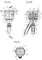
- Fig. 1a to 3b such as Fig. 5a to 8c show a medical push-button valve 1, which consists essentially of a valve housing 2, a formed in the valve housing 2 flow channel 3 and a valve piston 4 which is arranged between the flow channel 3 releasing and the flow passage 3 closing position displaceable in the valve housing 2.
- connection piece 6 is arranged, via which the push button valve 1 can be connected to a line leading to the patient 7.
- the push button valve 1 With the suction power coming from an external suction source, the push button valve 1 is acted upon via a suction line 8, which opens laterally into the valve housing 2 at an acute angle.
- valve piston 4 The adjustment of the valve piston 4 between the flow channel 3 releasing and the flow passage 3 closing position via a pressure element 9 which is mounted axially displaceable in the direction of the longitudinal axis 10 of the valve housing 2 in a proximal end 11 of the valve housing 2 arranged pusher housing 12. Furthermore, the pressure element 9 is rotatable relative to the pusher housing 12 about the longitudinal axis 10 of the valve housing 2.
- the interaction between the pressure element 9 and the valve piston 4 is designed so that the valve piston 4 is biased by a force acting on the pressure element 9 spring element 13 in the flow passage 3 closing position. This means that to open the flow channel 3, the pressure element 9 against the force of the spring element 13 in the direction of the longitudinal axis 10 of the valve housing 2 must be pressed distally to transfer the valve piston 4 in the flow channel 3 releasing position.
- the spring element 13 as a helical compression spring
- an elastic clamping ring 19 is arranged on the outside of the two housings 2 and 12, which is secured to the pusher housing 12 serves to connect the pusher housing 12 with the valve housing 2.
- the illustration Fig. 4 shows the pusher housing 12 from the valve housing 2 dismantled.
- the elastic clamping ring 19 connected to the pusher housing 12 is slipped over the upper part of the valve housing 2 and thus connects the two housings 2 and 12 with each other.
- the pusher housing 12 and the valve housing 2 can advantageously be separated from one another, wherein the valve piston 4 together with the pusher housing 12 can be withdrawn proximally from the valve housing 2, as shown in FIG Fig. 4 is shown.
- FIG. 1b shown sectional view of the push button valve 1 shows the unactuated starting position of the push button valve 1, in which the valve piston 4 completely closes the valve housing 2 formed in the flow channel 3 at the distal end.
- the closing body 15 arranged on the end of the valve piston 4 remote from the pressure element 9 seals radially circumferentially against the valve seat 17 formed in the valve housing 2 and thus closes the flow channel 3 in a substantially fluid-tight manner.
- the spring-loaded pressure element 9 and the pusher housing 12 via a pin-slot control 21 are coupled together, which is formed in the illustrated first embodiment as a bayonet lock 22 with a locking pin 23 and a slotted guide 24.
- the illustrated pin-slot control 21 consists of two over the circumference of the pusher housing 12 offset by 180 ° to each other arranged bayonet 22 22.
- the pictures Fig. 1b . 2 B and 3b are the two ratchet pins 23 of the bayonet 22.
- FIG. 2b shown sectional view of the push button valve 1 shows the actuated position of the push button valve 1, in which the valve piston 4 the valve housing 2 formed in the flow channel 3 completely releases the distal end.
- the closure body 15 of the valve piston 4 is no longer sealingly attached to the valve seat 17 formed in the valve housing 2, but is in the direction of the longitudinal axis 10 of the valve housing 2 away from the valve seat 17 to distal (in the figure Fig. 2b down).
- valve piston 4 of the in Fig. 1b shown, the flow channel 3 occluding position in the in Fig. 2b illustrated, the flow channel 3 releasing position is effected by pressing the spring-loaded pressure element 9 in the direction of the longitudinal axis 10 of the valve housing 2 to the distal direction (in the figure Fig. 2b downward) by a compressive force D.
- the axial pressure movement of the pressure element 9 is transmitted without play to the valve piston 4, whereby the closure body 15 is pressed from the sealing contact with the valve seat 17.
- the spring element 13 is arranged so that the pressure element 9 and thus also the valve piston 4 is biased in the flow channel 3 occlusive position, the surgeon must hold the pressure element 9 with the pressure force D down, as long as the suction pressure on the line 7 should be present.
- the slotted guide 24 at its upper end to a right-angled bend 25. Since the pressure element 9 is rotatable relative to the pusher housing 12 about the longitudinal axis 10 of the valve housing 2, the locking pin 23 can be rotated by turning the pressure element 9 from the in Fig. 2a position shown simply in the Fig. 3a transfer shown position in the bend 25. In this position of the locking pin 23 in the bend 25, the spring element 13, the pressure element 9 without the spring force of the spring element 13 counteracting compressive force D not back up in the closing the flow channel 3 position.
- a radially outward direction is provided at the proximal end of the spring-loaded pressure element 9 protruding actuating lever 26 is arranged.
- the illustration Fig. 4 shows one opposite the pictures Fig. 1a . 2a and 3a modified embodiment of the actuating lever 26th
- the pin-slot control 21 allows for the actuation of the pressure element 9 a guided displacement of the locking pin 23 in the slotted guide 24th
- the closure body 15 and 16 of the valve piston 4 are formed as thickenings of the valve piston 4 with conical transition regions.
- the conical design of the transition areas of the valve piston 4 to the actual closure body 15 and 16 prevents the flow channel 3 is closed or opened abruptly when adjusting the valve piston 4. Due to the conicity of the closure body 15 and 16, a slow opening and closing of the flow channel 3 is possible.
- Fig. 5a to 8c illustrated second embodiment for forming the push-button valve 1 differs from the embodiment shown above in that the pin-slot controller 21 is formed as a latching surface 27 and on the latching surface 27 slide-groove 28.
- the groove 28 is formed on the pressure element 9 and the locking surface 27 is formed as arranged on the inside of the pusher housing 12, semicircular radially inwardly extending surface.
- FIG. 5b shown sectional view of the push button valve 1 shows the unactuated starting position of the push button valve 1, in which the valve piston 4 completely closes the valve housing 2 formed in the flow channel 3 at the distal end.
- the closing body 15 arranged on the end of the valve piston 4 remote from the pressure element 9 seals radially circumferentially against the valve seat 17 formed in the valve housing 2 and thus closes the flow channel 3 in a substantially fluid-tight manner.
- Zu Kunststoffö Stamm 20 are formed in the pusher housing, can be sucked through the ambient air in the direction of the arrow U and discharged through the suction line 8, when the flow channel 3 is closed on the distal side via the valve piston 4.
- the pin-slot controller 21 via which the pressure element 9 and the pusher housing 12 are coupled together, as a latching surface 27 and 27 can be pushed onto the latching surface 27 groove.
- FIG. 6b shown sectional view of the push button valve 1 shows the actuated position of the push button valve 1, in which the valve piston 4 the valve housing 2 formed in the flow channel 3 completely releases the distal end.
- the closure body 15 of the valve piston 4 is no longer sealingly against the formed in the valve housing 2 valve seat 17, but is in the direction of the longitudinal axis 10 of the valve housing 2 away from the valve seat 17 to the distal (in the figure Fig. 6b down).
- valve piston 4 of the in Fig. 5b shown, the flow channel 3 occluding position in the in Fig. 6b illustrated, the flow channel 3 releasing position is effected by pressing the spring-loaded pressure element 9 in the direction of the longitudinal axis 10 of the valve housing 2 to the distal direction (in the figure Fig. 6b downward) by a compressive force D.
- the axial pressure movement of the pressure element 9 is transmitted without play to the valve piston 4, whereby the closure body 15 is pressed from the sealing contact with the valve seat 17.
- the spring element 13 is arranged so that the pressure element 9 and thus also the valve piston 4 is biased in the flow channel 3 occlusive position, the surgeon must hold the pressure element 9 with the pressure force D down, as long as the suction pressure on the line 7 should be present.
- the pictures Fig. 7a to 7c show an intermediate position between the representations according to Fig. 6a to 6c on the one hand and Fig. 8a to 8c on the other hand. These pictures Fig. 7a to 7c were recorded to better illustrate the movement between the groove 28 and the locking surface 27 for locking the pressure element 9.
- 9 recessed grips 29 are formed in the outer contour of the proximal end of the spring-loaded pressure element.
- the push-button valves 1 designed as described above are distinguished by the fact that they provide the surgeon with a simple and fatigue-free operation Enable one-handed operation, since the pressure element 9 and the valve piston 4 can be locked in a flow channel 3 releasing position and is ensured due to formation of the two closure body 15 and 16 on the common valve piston 4 that the opening and closing of the flow channel 3 and the sealing and Opening the pusher housing 12 relative to the ambient air U forcibly parallel to each other.
Abstract
Die Erfindung betrifft ein medizinisches Drucktastenventil (1) mit einem Ventilgehäuse (2), einem in dem Ventilgehäuse (2) ausgebildeten Strömungskanal (3) sowie mit einem Ventilkolben (4), der zwischen einer den Strömungskanal (3) freigebenden und einer den Strömungskanal (3) verschließenden Position verlagerbar im Ventilgehäuse (2) angeordnet ist, wobei der Ventilkolben (4) mit einem am Ventilgehäuse (2) gelagerten, über mindestens ein Federelement (13) federbelastetes Druckelement (9) in Wirkverbindung steht und der Ventilkolben (4) über das federbelastete Druckelement (9) in die den Strömungskanal (3) verschließende Position vorgespannt ist und das federbelastete Druckelement (9) in mindestens einer Position arretierbar ist, in der der mit dem Druckelement (9) in Wirkverbindung stehende Ventilkolben (4) den Strömungskanal (3) zumindest teilweise freigibt. Um ein medizinisches Drucktastenventil (1) zu schaffen, das eine einfache und ermüdungsfreie Einhandbedienung ermöglicht, wird erfindungsgemäß vorgeschlagen, dass in Richtung der Längsachse (10) des Ventilgehäuses (2) betrachtet am Ventilkolben (4) mit Abstand zueinander zwei Verschlusskörper (15 und 16) ausgebildet sind, die mit entsprechenden Ventilsitzen (17 und 18) zusammenwirken.The invention relates to a medical pushbutton valve (1) comprising a valve housing (2), a flow channel (3) formed in the valve housing (2) and a valve piston (4) which releases between a flow channel (3) and a flow channel (3). 3) closing position is arranged displaceably in the valve housing (2), wherein the valve piston (4) with a valve housing (2) mounted on at least one spring element (13) spring-loaded pressure element (9) is in operative connection and the valve piston (4) via the spring-loaded pressure element (9) is biased into the position closing the flow channel (3) and the spring-loaded pressure element (9) can be locked in at least one position in which the valve piston (4) in operative connection with the pressure element (9) forms the flow channel (4). 3) at least partially releases. In order to provide a medical pushbutton valve (1), which allows a simple and fatigue-free one-handed operation, the invention proposes that in the direction of the longitudinal axis (10) of the valve housing (2) viewed on the valve piston (4) at a distance from each other two closure body (15 and 16 ) are formed, which cooperate with corresponding valve seats (17 and 18).
Description
Die Erfindung betrifft ein medizinisches Drucktastenventil mit einem Ventilgehäuse, einem in dem Ventilgehäuse ausgebildeten Strömungskanal sowie mit einem Ventilkolben, der zwischen einer den Strömungskanal freigebenden und einer den Strömungskanal verschließenden Position verlagerbar im Ventilgehäuse angeordnet ist, wobei der Ventilkolben mit einem am Ventilgehäuse gelagerten, über mindestens ein Federelement federbelastetes Druckelement in Wirkverbindung steht und der Ventilkolben über das federbelastete Druckelement in die den Strömungskanal verschließende Position vorgespannt ist und das federbelastete Druckelement in mindestens einer Position arretierbar ist, in der der mit dem Druckelement in Wirkverbindung stehende Ventilkolben den Strömungskanal zumindest teilweise freigibt.The invention relates to a medical push button valve having a valve housing, a flow channel formed in the valve housing and a valve piston which is disposed displaceably between the flow channel releasing and the flow passage closing position in the valve housing, wherein the valve piston with a valve housing mounted on at least a spring element spring-loaded pressure element is in operative connection and the valve piston is biased via the spring-loaded pressure element in the flow passage closing position and the spring-loaded pressure element can be locked in at least one position in which the pressure member operatively connected to the valve piston releases the flow channel at least partially.
Während chirurgischer Operationen ist es häufig erforderlich, Flüssigkeiten, wie beispielsweise Blut oder Spülflüssigkeit, aus dem Operationsgebiet abzusaugen. Hierzu können mit einem Saugkanal ausgestattete chirurgische Instrumente über eine vorzugsweise flexible Saugleitung mit einer externen Saugquelle, beispielsweise einer Vakuumpumpe, verbunden werden.During surgical procedures, it is often necessary to aspirate fluids such as blood or irrigation fluid out of the surgical field. For this purpose, surgical instruments equipped with a suction channel can be connected to an external suction source, for example a vacuum pump, via a preferably flexible suction line.
Da in Operationssälen die Leistung der den Saugstrom erzeugenden Vakuumpumpe in der Regel nicht regulierbar ist, ist es üblich, die medizinischen Instrumente, wie beispielsweise Endoskope, mit einem Ventil auszustatten, über das der Saugstrom zu- und abschaltbar ist.Since the performance of the suction pump generating vacuum pump is usually not adjustable in operating theaters, it is common to provide the medical instruments, such as endoscopes, with a valve over which the suction flow is switched on and off.
Aus der Praxis ist es bekannt, ein solches Ventil zum Zu- und/oder Abschalten des Saugstroms als Drucktastenventil auszubilden, bei dem der den Strömungskanal freigebende oder verschließende Ventilkörper über ein federbelastetes Druckelement betätigbar ist, wobei der Ventilkörper über ein Federelement in die den Strömungskanal verschließende Position vorgespannt ist.From practice it is known to form such a valve for closing and / or switching off the suction flow as a push button valve, wherein the flow passage releasing or occluding valve body via a spring-loaded pressure element is actuated, wherein the valve body via a spring element in the flow passage occlusive Position is biased.
Diese bekannten Drucktastenventile, bei denen der Operateur zum Freigeben des Strömungskanals das federbelastete Druckelement eindrücken muss, haben sich in der Praxis bewährt. Nachteilig an dieser bekannten Konstruktion des Drucktastenventils ist, dass der Operateur das federbelastete Druckelement während des gesamten Saugvorgangs gedrückt halten muss, da der Ventilkörper in die den Saugkanal schließende Position vorgespannt ist.These known push-button valves, in which the surgeon must release the spring-loaded pressure element to release the flow channel, have proven themselves in practice. A disadvantage of this known construction of the push-button valve is that the surgeon must keep the spring-loaded pressure element pressed during the entire suction process, since the valve body is biased into the position closing the suction channel.
Bei manchen Untersuchungen und/oder Behandlungen, wie beispielsweise des Gallenganges, ist es erforderlich, eine kontinuierliche Absaugung zu gewährleisten, um ein Austreten von Sekreten aus einem anderen Arbeitskanalzugang zu verhindern. Das dauerhafte Drücken des federbelasteten Druckelements zur Gewährleistung der kontinuierlichen Absaugung ist für den Operateur anstrengend und kann aufgrund der gleichbleibenden Halteposition zum Verkrampfen des Fingers führen.In some examinations and / or treatments, such as bile duct, it is necessary to ensure continuous suction to prevent leakage of secretions from another working channel access. The permanent pressing of the spring-loaded pressure element to ensure continuous suction is tiring for the surgeon and can lead to cramping of the finger due to the constant holding position.
Ein gattungsgemäßes Ventil ist beispielsweise aus der
Durch die Ausbildung der Arretierposition des Druckelements in einer Position, in der der Ventilkörper den Strömungskanal freigibt, wird der Operateur von dem dauerhaften Niederdrücken des Druckelements befreit.By forming the locking position of the pressure element in a position in which the valve body releases the flow channel, the surgeon is released from the permanent depression of the pressure element.
Davon ausgehend liegt der Erfindung die Aufgabe zugrunde, ein weiteres medizinisches Drucktastenventil zu schaffen, das eine einfache und ermüdungsfreie Einhandbedienung ermöglicht.On this basis, the invention has for its object to provide a further medical pushbutton valve that allows easy and effortless one-handed operation.
Die Lösung dieser Aufgabenstellung ist erfindungsgemäß dadurch gekennzeichnet, dass in Richtung der Längsachse des Ventilgehäuses betrachtet am Ventilkolben mit Abstand zueinander zwei Verschlusskörper ausgebildet sind, die mit entsprechenden Ventilsitzen zusammenwirken.The solution to this problem is inventively characterized in that viewed in the direction of the longitudinal axis of the valve housing on the valve piston at a distance from each other two closure bodies are formed, which cooperate with corresponding valve seats.
Während der eine Verschlusskörper mit seinem zugehörigen Ventilsitzen zum Abdichten des Drückergehäuses gegenüber der Umgebungsluft dient lässt sich über den anderen Verschlusskörper mit seinem zugehörigen Ventilsitz der Strömungskanal patientenseitig verschließen.While a closure body with its associated valve seats serves to seal the pusher housing with respect to the ambient air, the flow channel can be closed on the patient side via the other closure body with its associated valve seat.
Die Ausbildung der zwei Verschlusskörper an dem gemeinsamen Ventilkolben stellt sicher, dass das Öffnen und Verschließen des Strömungskanals und das Abdichten und Öffnen des Drückergehäuses gegenüber der Umgebungsluft zwangsweise parallel zueinander erfolgt.The formation of the two closure bodies on the common valve piston ensures that the opening and closing of the flow channel and the sealing and opening of the pusher housing relative to the ambient air is forcibly parallel to each other.
Die Verschlusskörper des Ventilkolbens sind erfindungsgemäß als Verdickungen des Ventilkolbens mit konischen Übergangsbereichen ausgebildet sind. Die konische Ausbildung der Verschlusskörper verhindert, dass der Strömungskanal beim Verstellen des Ventilkolbens schlagartig geschlossen oder geöffnet wird. Aufgrund der Konizität der Verschlusskörper ist ein langsames Öffnen und Schließen des Strömungskanals möglich.The closure body of the valve piston are inventively designed as thickening of the valve piston with conical transition areas. The conical design of the closure body prevents the flow channel is suddenly closed or opened when adjusting the valve piston. Due to the conicity of the closure body, a slow opening and closing of the flow channel is possible.
Gemäß einer bevorzugten Ausführungsform der Erfindung ist das federbelastete Druckelement ausschließlich in der Position arretierbar, in der der mit dem Druckelement in Wirkverbindung stehende Ventilkolben den Strömungskanal vollständig freigibt. In dieser arretierten Position des Druckelements bzw. des mit diesem in Wirkverbindung stehenden Ventilkolbens liegt die volle Saugleistung am zum Patienten führenden distalen Ende des Ventilgehäuses an.According to a preferred embodiment of the invention, the spring-loaded pressure element can be locked exclusively in the position in which the valve piston, which is in operative connection with the pressure element, completely releases the flow channel. In this locked position of the pressure element or the valve piston operatively connected thereto, the full suction power is applied to the distal end of the valve housing leading to the patient.
Mit einer praktischen Ausführung der Erfindung wird vorgeschlagen, dass das federbelastete Druckelement in einem am proximalen Ende des Ventilgehäuses angeordneten Drückergehäuse gelagert ist, wobei das federbelastete Druckelement relativ zum Drückergehäuse um die Längsachse des Ventilgehäuses verdrehbar ist.With a practical embodiment of the invention it is proposed that the spring-loaded pressure element arranged in a at the proximal end of the valve housing Pusher housing is mounted, wherein the spring-loaded pressure element is rotatable relative to the pusher housing about the longitudinal axis of the valve housing.
Zur Ausbildung der Arretierfunktion des federbelasteten Druckelements wird mit der Erfindung vorgeschlagen, dass das federbelastete Druckelement und das Drückergehäuse über eine Zapfen-Schlitz-Steuerung miteinander gekoppelt sind. Die Zapfen-Schlitz-Steuerung ermöglicht eine geführte Verlagerung eines an einem Bauteil ausgebildeten Zapfens in einer Art Kulisse, die am anderen Bauteil ausgebildet ist, wobei für die Funktionsweise unerheblich ist, an welchem der Bauteile Druckelement oder Drückergehäuse der Zapfen oder die Führung für den Zapfen ausgebildet ist.To form the locking function of the spring-loaded pressure element is proposed with the invention that the spring-loaded pressure element and the pusher housing are coupled together via a pin-slot control. The pin-slot control allows a guided displacement of a pin formed on a component in a kind of backdrop, which is formed on the other component, which is irrelevant to the operation, on which of the components pressure element or pusher housing the pin or the guide for the pin is trained.
Gemäß einer ersten praktischen Ausführungsform zur Ausbildung der Zapfen-Schlitz-Steuerung wird mit der Erfindung vorgeschlagen, dass die Zapfen-Schlitz-Steuerung als Bajonettverschluss ausgebildet ist. Der Bajonettverschluss mit einem einseitig abgewinkelten Längsschlitz und einem in dem Längsschlitz geführten Zapfen zeichnet sich durch seine einfache Herstellbarkeit und einfache Handhabung aus. Durch einfaches Drücken und Verdrehen eines der beiden Bauteile relativ zum anderen Bauteil lässt sich der Bajonettverschluss schnell auch mit nur einer Hand betätigen.According to a first practical embodiment for the formation of the pin-slot control is proposed with the invention that the pin-slot control is designed as a bayonet closure. The bayonet closure with a one-sided angled longitudinal slot and guided in the longitudinal slot pin is characterized by its ease of manufacture and ease of use. By simply pressing and twisting one of the two components relative to the other component, the bayonet closure can be operated quickly with just one hand.
Vorteilhafterweise sind am Drückergehäuse zwei um 180° zueinander versetzt angeordnete Bajonettverschlüsse vorgesehen, um ein verkantungsfreies Betätigen zu gewährleisten. Je nach Umfang des Drückergehäuses können auch mehr als zwei Bajonettverschlüsse, wie beispielsweise drei um jeweils 120° zueinander versetzt angeordnete Bajonettverschlüsse, verwendet werden.Advantageously, two bayonet locks arranged offset by 180 ° to one another are provided on the pusher housing in order to ensure a tilt-free actuation. Depending on the size of the handle housing and more than two bayonet locks, such as three offset by 120 ° to each other arranged bayonet locks can be used.
Gemäß einer alternativen zweiten Ausführungsform zur Ausbildung der Zapfen-Schlitz-Steuerung wird mit der Erfindung vorgeschlagen, dass die Zapfen-Schlitz-Steuerung als Nut und Rastfläche ausgebildet ist, wobei die am verdrehbaren Druckelement ausgebildete Nut die am Drückergehäuse ausgebildete Rastfläche in der Arretierposition in sich aufnimmt.According to an alternative second embodiment for the formation of the pin-slot control is proposed with the invention that the pin-slot control is formed as a groove and locking surface, wherein the groove formed on the rotatable pressure element formed on the pusher housing locking surface in the locking position in itself receives.
Zur Ausbildung des auf das Druckelement wirkenden Federelements wird mit der Erfindung vorgeschlagen, dass das mindestens eine Federelement, über das Druckelement federbelastet ist, einstückig mit dem Druckelement oder dem Drückergehäuse ausgebildet ist, wobei die Federelastizität des Materials, aus dem das Druckelement bzw. das Drückergehäuse gefertigt sind, zur Ausbildung der Federeigenschaft herangezogen wird.In order to form the spring element acting on the pressure element, it is proposed with the invention that the at least one spring element is spring-loaded via the pressure element, is formed integrally with the pressure element or the pusher housing, wherein the spring elasticity of the material from which the pressure element or the pusher housing are made, is used to form the spring property.
Gemäß einer praktischen Ausführungsform der Erfindung wird vorgeschlagen, dass im Übergangsbereich vom Ventilgehäuse zum Drückergehäuse auf der Außenseite der beiden Gehäuse und ein die beiden Gehäuse miteinander verbindender elastischer Klemmring angeordnet ist. Diese Art der Verbindung der beiden Gehäuse über den elastischen Klemmring stellt eine besonders einfache und schnell durchzuführende Art der Montage und Demontage dar.According to a practical embodiment of the invention, it is proposed that in the transition region from the valve housing to the pusher housing on the outside of the two housings and the two housing interconnecting elastic clamping ring is arranged. This type of connection of the two housings via the elastic clamping ring represents a particularly simple and quickly performed type of assembly and disassembly.
Um eine besonders einfache Bedienung des federbelasteten Druckelements mit nur einer Hand oder auch nur einem Finger zu ermöglichen, wird mit der Erfindung vorgeschlagen, dass am proximalen Ende des federbelasteten Druckelements ein radial nach außen abstehender Betätigungshebel angeordnet ist. Über den Betätigungshebel lässt sich das federbelastete Druckelement einfach verdrehen, um die Arretierung über die Zapfen-Schlitz-Steuerung zu bewerkstelligen.In order to enable a particularly simple operation of the spring-loaded pressure element with only one hand or even a single finger, it is proposed with the invention that a radially outwardly projecting actuating lever is arranged at the proximal end of the spring-loaded pressure element. About the operating lever, the spring-loaded pressure element can easily rotate to accomplish the locking via the pin-slot control.
Schließlich wird mit der Erfindung vorgeschlagen, dass in der Außenkontur des proximalen Endes des federbelasteten Druckelements Griffmulden ausgebildet sind.Finally, it is proposed with the invention that gripping recesses are formed in the outer contour of the proximal end of the spring-loaded pressure element.
Weitere Merkmale und Vorteile der Erfindung ergeben sich anhand der zugehörigen Zeichnungen, in denen zwei Ausführungsbeispiele eines erfindungsgemäßen medizinischen Drucktastenventils nur beispielhaft dargestellt sind, ohne die Erfindung auf diese Ausführungsbeispiele zu beschränken. In den Zeichnungen zeigt:
- Fig. 1a
- eine teilweise freigeschnittene Seitenansicht einer ersten Ausführungsform eines erfindungsgemäßen Drucktastenventils, das Ventil in der den Strömungskanal verschließenden Position darstellend;
- Fig. 1b
- einen Längsschnitt entlang der Linie Ib-Ib gemäß
Fig. 1a ; - Fig. 2a
- eine Darstellung gemäß
Fig. 1a , jedoch das Ventil in einer den Strömungskanal freigebenden Position darstellend; - Fig. 2b
- einen Längsschnitt entlang der Linie IIb-IIb gemäß
Fig. 2a ; - Fig. 3a
- eine Darstellung gemäß
Fig. 2a , jedoch das Druckelement zusätzlich in einer arretierten Position darstellend; - Fig. 3b
- einen Längsschnitt entlang der Linie IIIb-IIIb gemäß
Fig. 3a ; - Fig. 4
- eine perspektivische Ansicht des vom Ventilgehäuse demontierten Drückergehäuses einschließlich Ventilkolben;
- Fig. 5a
- eine teilweise freigeschnittene Seitenansicht einer zweiten Ausführungsform eines erfindungsgemäßen Drucktastenventils, das Ventil in der den Strömungskanal verschließenden Position darstellend;
- Fig. 5b
- einen Längsschnitt entlang der Linie Vb-Vb gemäß
Fig. 5a ; - Fig. 5c
- einen Querschnitt entlang der Linie Vc-Vc gemäß
Fig. 5a ; - Fig. 6a
- eine Darstellung gemäß
Fig. 5a , jedoch das Ventil in einer den Strömungskanal freigebenden Position darstellend; - Fig. 6b
- einen Längsschnitt entlang der Linie VIb-VIb gemäß
Fig. 6a ; - Fig. 6c
- einen Querschnitt entlang der Linie VIc-VIc gemäß
Fig. 6a - Fig. 7a
- eine Darstellung gemäß
Fig. 6a , jedoch das Druckelement zusätzlich in einer fast vollständig arretierten Position darstellend; - Fig. 7b
- einen Längsschnitt entlang der Linie Vllb-Vllb gemäß
Fig. 7a ; - Fig. 7c
- einen Querschnitt entlang der Linie Vllc-Vllc gemäß
Fig. 7a - Fig. 8a
- eine Darstellung gemäß
Fig. 6a , jedoch das Druckelement zusätzlich in einer vollständig arretierten Position darstellend; - Fig. 8b
- einen Längsschnitt entlang der Linie Vlllb-Vlllb gemäß
Fig. 8a und - Fig. 8c
- einen Querschnitt entlang der Linie VIIIc-VIIIc gemäß
Fig. 8a
- Fig. 1a
- a partially cutaway side view of a first embodiment of a push-button valve according to the invention, the valve in the flow channel closing position representing;
- Fig. 1b
- a longitudinal section along the line Ib-Ib according to
Fig. 1a ; - Fig. 2a
- a representation according to
Fig. 1a however, the valve is in a position releasing the flow channel; - Fig. 2b
- a longitudinal section along the line IIb-IIb according to
Fig. 2a ; - Fig. 3a
- a representation according to
Fig. 2a but additionally presenting the pressure member in a locked position; - Fig. 3b
- a longitudinal section along the line IIIb-IIIb according to
Fig. 3a ; - Fig. 4
- a perspective view of the valve housing dismantled handle housing including valve piston;
- Fig. 5a
- a partially cutaway side view of a second embodiment of a push button valve according to the invention, the valve in the flow passage closing position representing;
- Fig. 5b
- a longitudinal section along the line Vb-Vb according to
Fig. 5a ; - Fig. 5c
- a cross section along the line Vc-Vc according to
Fig. 5a ; - Fig. 6a
- a representation according to
Fig. 5a however, the valve is in a position releasing the flow channel; - Fig. 6b
- a longitudinal section along the line VIb-VIb according to
Fig. 6a ; - Fig. 6c
- a cross section along the line VIc-VIc according to
Fig. 6a - Fig. 7a
- a representation according to
Fig. 6a but additionally presenting the pressure element in an almost fully locked position; - Fig. 7b
- a longitudinal section along the line Vllb-Vllb according to
Fig. 7a ; - Fig. 7c
- a cross section along the line Vllc-Vllc according to
Fig. 7a - Fig. 8a
- a representation according to
Fig. 6a but additionally presenting the pressure element in a fully locked position; - Fig. 8b
- a longitudinal section along the line VIIIb-VIIIb according to
Fig. 8a and - Fig. 8c
- a cross section along the line VIIIc-VIIIc according to
Fig. 8a
Die Abbildung
Wie aus der geschnittenen Seitenansichten gemäß den Abbildungen
Mit der von einer externen Saugquelle stammenden Saugleistung wird das Drucktastenventil 1 über eine Saugleitung 8 beaufschlagt, die unter einem spitzen Winkel seitlich in das Ventilgehäuse 2 mündet.With the suction power coming from an external suction source, the
Das Verstellen des Ventilkolbens 4 zwischen der den Strömungskanal 3 freigebenden und der den Strömungskanal 3 verschließenden Position erfolgt über ein Druckelement 9, das in Richtung der Längsachse 10 des Ventilgehäuses 2 axial verlagerbar in einem am proximalen Ende 11 des Ventilgehäuses 2 angeordneten Drückergehäuse 12 gelagert ist. Weiterhin ist das Druckelement 9 relativ zum Drückergehäuse 12 um die Längsachse 10 des Ventilgehäuses 2 verdrehbar.The adjustment of the
Das Zusammenwirken zwischen dem Druckelement 9 und dem Ventilkolben 4 ist dabei so ausgelegt, dass der Ventilkolben 4 über ein auf das Druckelement 9 wirkendes Federelement 13 in die den Strömungskanal 3 verschließende Position vorgespannt ist. Dies bedeutet, dass zum Öffnen des Strömungskanals 3 das Druckelement 9 gegen die Kraft des Federelements 13 in Richtung der Längsachse 10 des Ventilgehäuses 2 nach distal gedrückt werden muss, um den Ventilkolben 4 in die den Strömungskanal 3 freigebende Position zu überführen.The interaction between the
Alternativ zu der dargestellten Ausbildung des Federelements 13 als wendelförmige Druckfeder ist es auch möglich, das Federelement, über das Druckelement 9 federbelastet ist, einstückig mit dem Druckelement 9 oder mit dem Drückergehäuse 12 auszubilden, wobei die Federelastizität des Materials, aus dem das Druckelement 9 bzw. das Drückergehäuse 12 gefertigt sind, zur Ausbildung der Federeigenschaft herangezogen wird.As an alternative to the illustrated construction of the
Wie beispielsweise aus der Abbildung
Im Übergangsbereich vom Ventilgehäuse 2 zum Drückergehäuse 12 ist auf der Außenseite der beiden Gehäuse 2 und 12 ein elastischer Klemmring 19 angeordnet, der am Drückergehäuse 12 festegelegt dazu dient, das Drückergehäuse 12 mit dem Ventilgehäuse 2 zu verbinden. Die Abbildung
Zu Reinigungszwecken lassen sich vorteilhafterweise das Drückergehäuse 12 und das Ventilgehäuse 2 voneinander trennen, wobei der Ventilkolben 4 zusammen mit dem Drückergehäuse 12 nach proximal aus dem Ventilgehäuse 2 ziehbar ist, wie dies in
Die Arbeitsweise des medizinischen Drucktastenventils 1 wird nachfolgend anhand der Abbildungen
Die in
Über das sich einseitig am Drückergehäuse 12 abstützende Federelement 13 wird das Druckelement 9, das bei der in den Abbildungen
Da in Operationssälen die Leistung der den Saugstrom erzeugenden Vakuumpumpe in der Regel nicht regulierbar ist, also auch in geschlossenen Position des Ventilkolbens 4 über die Saugleitung 8 ein dauerhafter Saugstrom in Richtung des Pfeils S am Drucktastenventil 1 anliegt, sind im Drückergehäuse 12 Zuluftöffnungen 20 ausgebildet, über die Umgebungsluft in Richtung des Pfeils U angesaugt und über die Saugleitung 8 abgeführt werden kann. Durch die über die Zuluftöffnungen 20 ansaugbare Umgebungsluft U wird verhindert, dass aufgrund der dauerhaften Saugleistung über die Saugleitung 8 ein Unterdruck im Ventilgehäuse 2 entsteht, der einerseits Dichtelemente im Drucktastenventil 1 stark beanspruchen würde und andererseits das Betätigen des Ventilkolbens 4 erschweren könnte.Since in operating theaters, the power of the vacuum pump generating the suction flow is usually not adjustable, so even in the closed position of the
Wie insbesondere aus den Abbildungen
Die dargestellte Zapfen-Schlitz-Steuerung 21 besteht aus zwei über den Umfang des Drückergehäuses 12 um 180° Grad zueinander versetzt angeordneten Bajonettverschlüssen 22. Den Abbildungen
Alternativ zu der Verwendung von zwei um 180° zueinander versetzt angeordneten Bajonettverschlüssen 22 können je nach Umfang des Drückergehäuses 12 auch mehr als zwei Bajonettverschlüsse 22, wie beispielsweise drei um jeweils 120° zueinander versetzt angeordnete Bajonettverschlüsse 22, verwendet werden.As an alternative to the use of two offset by 180 ° to each other arranged
Bei der in
Die in
Das Verstellen des Ventilkolbens 4 von der in
In dieser geöffneten Position des Strömungskanals 3 wird der Zustrom der Umgebungsluft U über die Zuluftöffnungen 20 durch den zweiten, dem Druckelement 9 nahe angeordneten Verschlusskörper 16 des Ventilkolbens 4 verschlossen, da dieser Verschlusskörper 16 bei herabgedrücktem Druckelement 9 radial umfänglich abdichtend an dem korrespondierenden zweiten im Ventilgehäuse 2 ausgebildeten Ventilsitz 18 anliegt.In this open position of the
Das Verschließen des in
Bei der in
Da das Federelement 13 so angeordnet ist, dass das Druckelement 9 und somit auch der Ventilkolben 4 in die den Strömungskanal 3 verschließende Position vorgespannt ist, muss der Operateur das Druckelement 9 mit der Druckkraft D nach unten gedrückt halten, so lange der Saugdruck an der Leitung 7 anliegen soll.Since the
Um den Operateur zu entlasten, ist es gemäß der in den Abbildungen
Zu diesem Zweck weist die Kulissenführung 24 an ihren oberen Ende eine rechtwinklige Abwinklung 25 auf. Da das Druckelement 9 relativ zum Drückergehäuse 12 um die Längsachse 10 des Ventilgehäuses 2 verdrehbar ist, lässt sich der Raststift 23 durch Verdrehen des Druckelements 9 aus der in
Um das Verdrehen des Druckelements 9 zum Betätigen des Bajonettverschlusses 22 zu erleichtern und auch eine Betätigung mit nur einem Finger zu ermöglichen, ist am proximalen Ende des federbelasteten Druckelements 9 ein radial nach außen abstehender Betätigungshebel 26 angeordnet. Die Abbildung
Zum erneuten Verschließen des Strömungskanals 3 durch den Ventilkolben 4 muss der Operateur nur das Druckelement 9 wieder um die Längsachse 10 des Ventilgehäuses 2 verdrehen, bis der Raststift 23 wieder außer Eingriff mit der Abwinklung 25 tritt, wie dies in
Die Zapfen-Schlitz-Steuerung 21 ermöglicht bei der Betätigung des Druckelements 9 eine geführte Verlagerung des Raststiftes 23 in der Kulissenführung 24.The pin-
Auch wenn in den Abbildungen
Wie weiterhin aus den Abbildungen ersichtlich, sind die Verschlusskörper 15 und 16 des Ventilkolbens 4 als Verdickungen des Ventilkolbens 4 mit konischen Übergangsbereichen ausgebildet. Die konische Ausbildung der Übergangsbereiche vom Ventilkolben 4 zum eigentlichen Verschlusskörper 15 und 16 verhindert, dass der Strömungskanal 3 beim Verstellen des Ventilkolbens 4 schlagartig geschlossen oder geöffnet wird. Aufgrund der Konizität der Verschlusskörper 15 und 16 ist ein langsames Öffnen und Schließen des Strömungskanals 3 möglich.As further shown in the figures, the
Die in
Die Nut 28 ist dabei am Druckelement 9 ausgebildet ist und die Rastfläche 27 als an der Innenseite des Drückergehäuses 12 angeordnete, sich halbkreisförmig radial nach innen erstreckende Fläche ausgebildet.The
Die in
Auch bei dieser Ausführungsform sind im Drückergehäuse 12 Zuluftöffnungen 20 ausgebildet, über die Umgebungsluft in Richtung des Pfeils U angesaugt und über die Saugleitung 8 abgeführt werden kann, wenn der Strömungskanal 3 distalseitig über den Ventilkolben 4 verschlossen ist.Also in this
Wie insbesondere aus den Abbildungen
Bei der in
Die in
Das Verstellen des Ventilkolbens 4 von der in
In dieser geöffneten Position des Strömungskanals 3 wird der Zustrom der Umgebungsluft U über die Zuluftöffnungen 20 durch den zweiten, dem Druckelement 9 nahe angeordneten Verschlusskörper 16 des Ventilkolbens 4 verschlossen, da dieser Verschlusskörper 16 bei herabgedrücktem Druckelement 9 radial umfänglich abdichtend an dem korrespondierenden zweiten im Ventilgehäuse 2 ausgebildeten Ventilsitz 18 anliegt.In this open position of the
Das Verschließen des Zustroms der Umgebungsluft U bewirkt, dass nunmehr die volle Saugleistung der Saugleitung 8 am Strömungskanal 3 anliegt und über die Leitung 7 Flüssigkeit vom Patienten her in Richtung der durch den Pfeil gekennzeichneten Absaugrichtung A abgesaugt werden kann.Closing the inflow of the ambient air U causes now the full suction power of the
Bei der in
Da das Federelement 13 so angeordnet ist, dass das Druckelement 9 und somit auch der Ventilkolben 4 in die den Strömungskanal 3 verschließende Position vorgespannt ist, muss der Operateur das Druckelement 9 mit der Druckkraft D nach unten gedrückt halten, so lange der Saugdruck an der Leitung 7 anliegen soll.Since the
Um den Operateur zu entlasten, ist es gemäß der in den Abbildungen
Zu diesem Zweck lässt durch Verdrehen des Druckelements 9 um die Längsachse 10 des Ventilgehäuses 2 die am Druckelement 9 ausgebildete Nut 28 in die in den Abbildungen
Die Abbildungen
Um das Verdrehen des Druckelements 9 zum Betätigen der Zapfen-Schlitz-Steuerung 19 zu erleichtern und auch eine Betätigung mit nur einem Finger zu ermöglichen, sind in der Außenkontur des proximalen Endes des federbelasteten Druckelements 9 Griffmulden 29 ausgebildet.In order to facilitate the rotation of the
Zum erneuten Verschließen des Strömungskanals 3 durch den Ventilkolben 4 muss der Operateur nur das Druckelement 9 wieder um die Längsachse 10 des Ventilgehäuses 2 verdrehen, bis die Nut 28 wieder außer Eingriff mit der Rastfläche 27 tritt. Sobald der Operateur dann keine Druckkraft D mehr auf das Druckelement 9 ausübt, drückt das Federelement 13 das Druckelement 9 und somit auch den Ventilkolben 4 zurück in die den Strömungskanal 3 verschließende Position gemäß
Die wie zuvor beschrieben ausgebildeten Drucktastenventile 1 zeichnen sich dadurch aus, dass diese dem Operateur eine einfache und ermüdungsfreie Einhandbedienung ermöglichen, da das Druckelement 9 bzw. der Ventilkolben 4 in einer den Strömungskanal 3 freigebenden Position arretierbar ist und aufgrund Ausbildung der zwei Verschlusskörper 15 und 16 an dem gemeinsamen Ventilkolben 4 sichergestellt wird, dass das Öffnen und Verschließen des Strömungskanals 3 und das Abdichten und Öffnen des Drückergehäuses 12 gegenüber der Umgebungsluft U zwangsweise parallel zueinander erfolgt.The push-
- 11
- DrucktastenventilPushbutton valve
- 22
- Ventilgehäusevalve housing
- 33
- Strömungskanalflow channel
- 44
- Ventilkolbenplunger
- 55
- distales Ende (Ventilgehäuse)distal end (valve housing)
- 66
- Anschlussstutzenspigot
- 77
- Leitungmanagement
- 88th
- Saugleitungsuction
- 99
- Druckelementpressure element
- 1010
- Längsachselongitudinal axis
- 1111
- proximales Ende (Ventilgehäuse)proximal end (valve housing)
- 1212
- Drückergehäusepusher housing
- 1313
- Federelementspring element
- 1515
- Verschlusskörperclosure body
- 1616
- Verschlusskörperclosure body
- 1717
- Ventilsitzvalve seat
- 1818
- Ventilsitzvalve seat
- 1919
- Klemmringclamping ring
- 2020
- Zuluftöffnungair intake opening
- 2121
- Zapfen-Schlitz-SteuerungPin-slot-control
- 2222
- Bajonettverschlussbayonet catch
- 2323
- RaststiftPlunger
- 2424
- Kulissenführunglink guide
- 2525
- Abwinklungangling
- 2626
- Betätigungshebelactuating lever
- 2727
- RastflächeRest area
- 2828
- Nutgroove
- 2929
- Griffmuldegrip
- AA
- Absaugrichtungsuction direction
- DD
- Druckkraftthrust
- SS
- SaugstromrichtungSaugstromrichtung
- UU
- Umgebungsluftambient air
Claims (12)
dadurch gekennzeichnet,
dass in Richtung der Längsachse (10) des Ventilgehäuses (2) betrachtet am Ventilkolben (4) mit Abstand zueinander zwei Verschlusskörper (15 und 16) ausgebildet sind, die mit entsprechenden Ventilsitzen (17 und 18) zusammenwirken.Medical pushbutton valve having a valve housing (2), a flow channel (3) formed in the valve housing (2) and a valve piston (4) displaceable in the valve housing between a position releasing the flow channel (3) and closing the flow channel (3) (2) is arranged, wherein the valve piston (4) with a valve housing (2) mounted on at least one spring element (13) spring-loaded pressure element (9) is in operative connection and the valve piston (4) via the spring-loaded pressure element (9) in the position closing the flow channel (3) is prestressed and the spring-loaded pressure element (9) can be locked in at least one position in which the valve piston (4) operatively connected to the pressure element (9) at least partially releases the flow channel (3),
characterized,
that in the direction of the longitudinal axis (10) of the valve housing (2) viewed on the valve piston (4) at a distance from each other two closure body (15 and 16) are formed, which cooperate with corresponding valve seats (17 and 18).
Applications Claiming Priority (1)
| Application Number | Priority Date | Filing Date | Title |
|---|---|---|---|
| DE102017005718.4A DE102017005718A1 (en) | 2017-06-16 | 2017-06-16 | Medical push button valve |
Publications (2)
| Publication Number | Publication Date |
|---|---|
| EP3417906A1 true EP3417906A1 (en) | 2018-12-26 |
| EP3417906B1 EP3417906B1 (en) | 2022-03-09 |
Family
ID=62712751
Family Applications (1)
| Application Number | Title | Priority Date | Filing Date |
|---|---|---|---|
| EP18176767.4A Active EP3417906B1 (en) | 2017-06-16 | 2018-06-08 | Medical push key valve |
Country Status (3)
| Country | Link |
|---|---|
| US (1) | US10758647B2 (en) |
| EP (1) | EP3417906B1 (en) |
| DE (1) | DE102017005718A1 (en) |
Cited By (2)
| Publication number | Priority date | Publication date | Assignee | Title |
|---|---|---|---|---|
| CN110477931A (en) * | 2019-08-09 | 2019-11-22 | 王立盼 | A kind of blood collection device that clinical examination is easy to use |
| DE102021109024A1 (en) | 2021-04-12 | 2022-10-13 | Karl Storz Se & Co. Kg | Valve for a medical instrument and medical instrument |
Families Citing this family (9)
| Publication number | Priority date | Publication date | Assignee | Title |
|---|---|---|---|---|
| EP3979891A1 (en) * | 2019-06-10 | 2022-04-13 | Boston Scientific Scimed, Inc. | Medical cleaning valve |
| US11828416B2 (en) * | 2019-08-20 | 2023-11-28 | Rotarex S.A. | Gas cylinder valve with radially extending operating handle |
| AU2021241497A1 (en) * | 2020-03-24 | 2022-10-06 | Boston Scientific Scimed, Inc. | Devices, systems, and methods for controlling fluids in endoscope systems |
| DE102020110399A1 (en) | 2020-04-16 | 2021-10-21 | Rs-Technik Cad-Cam Gmbh | Cock for the passage of fluids |
| US11759599B2 (en) * | 2020-06-26 | 2023-09-19 | GE Precision Healthcare LLC | Systems and method for valve control in a fill assembly of a medical device |
| AU2021396166A1 (en) * | 2020-12-07 | 2023-07-27 | Adaptivendo Llc | Endoscope systems and assemblies |
| JP7348215B2 (en) | 2021-01-08 | 2023-09-20 | Ckd株式会社 | Valves for fluid pressure equipment |
| USD996570S1 (en) | 2021-05-04 | 2023-08-22 | Hydrapak Llc | Dispensing valve |
| CN218165244U (en) * | 2021-05-12 | 2022-12-30 | 思未来医疗科技有限公司 | Suction valve of endoscope |
Citations (4)
| Publication number | Priority date | Publication date | Assignee | Title |
|---|---|---|---|---|
| US5427144A (en) * | 1994-02-24 | 1995-06-27 | Deumed Group Inc. | Valve means with fluid retraction means |
| JPH1052399A (en) * | 1996-08-09 | 1998-02-24 | Fuji Photo Optical Co Ltd | Valve device for endoscope |
| EP1707107A1 (en) * | 2005-03-31 | 2006-10-04 | Fujinon Corporation | Endoscope |
| EP2997876A1 (en) * | 2014-09-18 | 2016-03-23 | Karl Storz GmbH & Co. KG | Insufflation and flush valve and endoscope comprising an insufflation and flush valve |
Family Cites Families (12)
| Publication number | Priority date | Publication date | Assignee | Title |
|---|---|---|---|---|
| US1463735A (en) * | 1922-03-18 | 1923-07-31 | Varrieur Henry Oza | Combined closure and faucet for liquid containers |
| US2606736A (en) * | 1947-08-07 | 1952-08-12 | Keller Tool Co | Push type reversing valve |
| US5228646A (en) * | 1992-07-06 | 1993-07-20 | Kenneth Raines | Latching trumpet valve for medical infusions |
| US5364070A (en) * | 1993-07-22 | 1994-11-15 | Transamerican Technologies International | High pressure micro valve |
| US5433410A (en) * | 1994-05-27 | 1995-07-18 | Foltz; Timothy J. | Drain valve |
| US6364853B1 (en) * | 2000-09-11 | 2002-04-02 | Scion International, Inc. | Irrigation and suction valve and method therefor |
| DE20020298U1 (en) * | 2000-11-23 | 2001-04-05 | Scherer Norbert | Single lever mixer tap for sinks, showers, etc. |
| DE102005029756A1 (en) * | 2005-06-20 | 2007-01-11 | Karl Storz Gmbh & Co. Kg | Key-operated valve for medical instruments for sucking and rinsing |
| US20110233439A1 (en) * | 2010-03-26 | 2011-09-29 | Pacific Hospital Supply Co., Ltd | Control head |
| DE102010045680A1 (en) * | 2010-09-17 | 2012-03-22 | Karl Storz Gmbh & Co. Kg | Medical instrument for sucking and rinsing |
| DE102014001251B3 (en) * | 2014-02-03 | 2015-02-19 | Olympus Winter & Ibe Gmbh | Stopcock for the fluid channel of a surgical instrument |
| DE102016216023A1 (en) * | 2016-08-25 | 2018-03-01 | Richard Wolf Gmbh | Medical instrument |
-
2017
- 2017-06-16 DE DE102017005718.4A patent/DE102017005718A1/en active Pending
-
2018
- 2018-06-08 EP EP18176767.4A patent/EP3417906B1/en active Active
- 2018-06-18 US US16/010,924 patent/US10758647B2/en active Active
Patent Citations (4)
| Publication number | Priority date | Publication date | Assignee | Title |
|---|---|---|---|---|
| US5427144A (en) * | 1994-02-24 | 1995-06-27 | Deumed Group Inc. | Valve means with fluid retraction means |
| JPH1052399A (en) * | 1996-08-09 | 1998-02-24 | Fuji Photo Optical Co Ltd | Valve device for endoscope |
| EP1707107A1 (en) * | 2005-03-31 | 2006-10-04 | Fujinon Corporation | Endoscope |
| EP2997876A1 (en) * | 2014-09-18 | 2016-03-23 | Karl Storz GmbH & Co. KG | Insufflation and flush valve and endoscope comprising an insufflation and flush valve |
Cited By (4)
| Publication number | Priority date | Publication date | Assignee | Title |
|---|---|---|---|---|
| CN110477931A (en) * | 2019-08-09 | 2019-11-22 | 王立盼 | A kind of blood collection device that clinical examination is easy to use |
| DE102021109024A1 (en) | 2021-04-12 | 2022-10-13 | Karl Storz Se & Co. Kg | Valve for a medical instrument and medical instrument |
| WO2022218933A1 (en) | 2021-04-12 | 2022-10-20 | Karl Storz Se & Co. Kg | Valve for a medical instrument, and medical instrument |
| DE102021109024B4 (en) | 2021-04-12 | 2023-02-23 | Karl Storz Se & Co. Kg | Valve for a medical instrument and medical instrument |
Also Published As
| Publication number | Publication date |
|---|---|
| EP3417906B1 (en) | 2022-03-09 |
| US10758647B2 (en) | 2020-09-01 |
| DE102017005718A1 (en) | 2018-12-20 |
| US20180361034A1 (en) | 2018-12-20 |
Similar Documents
| Publication | Publication Date | Title |
|---|---|---|
| EP3417906B1 (en) | Medical push key valve | |
| DE2817922C2 (en) | Sealing device for an endoscope | |
| DE4234990C2 (en) | Trocar sleeve | |
| EP1346681A2 (en) | Suction valve for an endoscope | |
| DE2527230B2 (en) | Suction irrigator | |
| EP0307743A1 (en) | Locking valve for a device to drain or infuse liquids | |
| DE60106731T2 (en) | VALVE DEVICE | |
| EP1329231A1 (en) | Medical instrument for irrigation and/or suction | |
| EP3730705A1 (en) | Sanitary valve | |
| EP3015082B1 (en) | Dismountable medical instrument | |
| DE2644947A1 (en) | Closure unit for compressible container - has sleeve movable so end opening fits lightly or tightly fits on closure stem | |
| DE19704579C2 (en) | Coupling for the tight connection of two shaft-like medical instruments | |
| DE4303026C2 (en) | Trocar for minimally invasive surgery | |
| EP1974828A2 (en) | Dispensing device for fluids | |
| EP3679978B1 (en) | Catheter valve and closure device for a catheter valve | |
| DE102016216023A1 (en) | Medical instrument | |
| DE102008018894B3 (en) | Pneumatic hand strapping tool | |
| EP3787983B1 (en) | Cream spender | |
| WO2013000678A1 (en) | Surgical instrument | |
| EP0502321A1 (en) | Shut-off device for a liquid conduit, particularly for a liquid tapping device or an infusion device | |
| DE102010045680A1 (en) | Medical instrument for sucking and rinsing | |
| EP2526992A1 (en) | Catheter valve | |
| DE4210984A1 (en) | Trocar for minimal invasive surgery - has internal lip valve which opens by insertion of instrument and closes when instrument is withdrawn due top compression springs in guides | |
| EP3001081B1 (en) | Angle valve with handwheel | |
| DE102021109024B4 (en) | Valve for a medical instrument and medical instrument |
Legal Events
| Date | Code | Title | Description |
|---|---|---|---|
| PUAI | Public reference made under article 153(3) epc to a published international application that has entered the european phase |
Free format text: ORIGINAL CODE: 0009012 |
|
| STAA | Information on the status of an ep patent application or granted ep patent |
Free format text: STATUS: THE APPLICATION HAS BEEN PUBLISHED |
|
| AK | Designated contracting states |
Kind code of ref document: A1 Designated state(s): AL AT BE BG CH CY CZ DE DK EE ES FI FR GB GR HR HU IE IS IT LI LT LU LV MC MK MT NL NO PL PT RO RS SE SI SK SM TR |
|
| AX | Request for extension of the european patent |
Extension state: BA ME |
|
| STAA | Information on the status of an ep patent application or granted ep patent |
Free format text: STATUS: REQUEST FOR EXAMINATION WAS MADE |
|
| 17P | Request for examination filed |
Effective date: 20190620 |
|
| RBV | Designated contracting states (corrected) |
Designated state(s): AL AT BE BG CH CY CZ DE DK EE ES FI FR GB GR HR HU IE IS IT LI LT LU LV MC MK MT NL NO PL PT RO RS SE SI SK SM TR |
|
| RIC1 | Information provided on ipc code assigned before grant |
Ipc: F16K 31/528 20060101ALI20210809BHEP Ipc: F16K 31/524 20060101ALI20210809BHEP Ipc: F16K 11/07 20060101ALI20210809BHEP Ipc: A61M 5/168 20060101ALI20210809BHEP Ipc: F16K 27/04 20060101ALI20210809BHEP Ipc: F16K 3/24 20060101ALI20210809BHEP Ipc: A61B 1/015 20060101ALI20210809BHEP Ipc: A61M 1/00 20060101ALI20210809BHEP Ipc: A61B 1/00 20060101ALI20210809BHEP Ipc: A61M 39/22 20060101AFI20210809BHEP |
|
| GRAP | Despatch of communication of intention to grant a patent |
Free format text: ORIGINAL CODE: EPIDOSNIGR1 |
|
| STAA | Information on the status of an ep patent application or granted ep patent |
Free format text: STATUS: GRANT OF PATENT IS INTENDED |
|
| INTG | Intention to grant announced |
Effective date: 20211005 |
|
| GRAS | Grant fee paid |
Free format text: ORIGINAL CODE: EPIDOSNIGR3 |
|
| GRAA | (expected) grant |
Free format text: ORIGINAL CODE: 0009210 |
|
| STAA | Information on the status of an ep patent application or granted ep patent |
Free format text: STATUS: THE PATENT HAS BEEN GRANTED |
|
| AK | Designated contracting states |
Kind code of ref document: B1 Designated state(s): AL AT BE BG CH CY CZ DE DK EE ES FI FR GB GR HR HU IE IS IT LI LT LU LV MC MK MT NL NO PL PT RO RS SE SI SK SM TR |
|
| REG | Reference to a national code |
Ref country code: CH Ref legal event code: EP Ref country code: AT Ref legal event code: REF Ref document number: 1473619 Country of ref document: AT Kind code of ref document: T Effective date: 20220315 |
|
| REG | Reference to a national code |
Ref country code: IE Ref legal event code: FG4D Free format text: LANGUAGE OF EP DOCUMENT: GERMAN |
|
| REG | Reference to a national code |
Ref country code: DE Ref legal event code: R096 Ref document number: 502018008993 Country of ref document: DE |
|
| REG | Reference to a national code |
Ref country code: LT Ref legal event code: MG9D |
|
| REG | Reference to a national code |
Ref country code: NL Ref legal event code: MP Effective date: 20220309 |
|
| PG25 | Lapsed in a contracting state [announced via postgrant information from national office to epo] |
Ref country code: SE Free format text: LAPSE BECAUSE OF FAILURE TO SUBMIT A TRANSLATION OF THE DESCRIPTION OR TO PAY THE FEE WITHIN THE PRESCRIBED TIME-LIMIT Effective date: 20220309 Ref country code: RS Free format text: LAPSE BECAUSE OF FAILURE TO SUBMIT A TRANSLATION OF THE DESCRIPTION OR TO PAY THE FEE WITHIN THE PRESCRIBED TIME-LIMIT Effective date: 20220309 Ref country code: NO Free format text: LAPSE BECAUSE OF FAILURE TO SUBMIT A TRANSLATION OF THE DESCRIPTION OR TO PAY THE FEE WITHIN THE PRESCRIBED TIME-LIMIT Effective date: 20220609 Ref country code: LT Free format text: LAPSE BECAUSE OF FAILURE TO SUBMIT A TRANSLATION OF THE DESCRIPTION OR TO PAY THE FEE WITHIN THE PRESCRIBED TIME-LIMIT Effective date: 20220309 Ref country code: HR Free format text: LAPSE BECAUSE OF FAILURE TO SUBMIT A TRANSLATION OF THE DESCRIPTION OR TO PAY THE FEE WITHIN THE PRESCRIBED TIME-LIMIT Effective date: 20220309 Ref country code: BG Free format text: LAPSE BECAUSE OF FAILURE TO SUBMIT A TRANSLATION OF THE DESCRIPTION OR TO PAY THE FEE WITHIN THE PRESCRIBED TIME-LIMIT Effective date: 20220609 |
|
| PG25 | Lapsed in a contracting state [announced via postgrant information from national office to epo] |
Ref country code: LV Free format text: LAPSE BECAUSE OF FAILURE TO SUBMIT A TRANSLATION OF THE DESCRIPTION OR TO PAY THE FEE WITHIN THE PRESCRIBED TIME-LIMIT Effective date: 20220309 Ref country code: GR Free format text: LAPSE BECAUSE OF FAILURE TO SUBMIT A TRANSLATION OF THE DESCRIPTION OR TO PAY THE FEE WITHIN THE PRESCRIBED TIME-LIMIT Effective date: 20220610 Ref country code: FI Free format text: LAPSE BECAUSE OF FAILURE TO SUBMIT A TRANSLATION OF THE DESCRIPTION OR TO PAY THE FEE WITHIN THE PRESCRIBED TIME-LIMIT Effective date: 20220309 |
|
| PG25 | Lapsed in a contracting state [announced via postgrant information from national office to epo] |
Ref country code: NL Free format text: LAPSE BECAUSE OF FAILURE TO SUBMIT A TRANSLATION OF THE DESCRIPTION OR TO PAY THE FEE WITHIN THE PRESCRIBED TIME-LIMIT Effective date: 20220309 |
|
| PG25 | Lapsed in a contracting state [announced via postgrant information from national office to epo] |
Ref country code: SM Free format text: LAPSE BECAUSE OF FAILURE TO SUBMIT A TRANSLATION OF THE DESCRIPTION OR TO PAY THE FEE WITHIN THE PRESCRIBED TIME-LIMIT Effective date: 20220309 Ref country code: SK Free format text: LAPSE BECAUSE OF FAILURE TO SUBMIT A TRANSLATION OF THE DESCRIPTION OR TO PAY THE FEE WITHIN THE PRESCRIBED TIME-LIMIT Effective date: 20220309 Ref country code: RO Free format text: LAPSE BECAUSE OF FAILURE TO SUBMIT A TRANSLATION OF THE DESCRIPTION OR TO PAY THE FEE WITHIN THE PRESCRIBED TIME-LIMIT Effective date: 20220309 Ref country code: PT Free format text: LAPSE BECAUSE OF FAILURE TO SUBMIT A TRANSLATION OF THE DESCRIPTION OR TO PAY THE FEE WITHIN THE PRESCRIBED TIME-LIMIT Effective date: 20220711 Ref country code: ES Free format text: LAPSE BECAUSE OF FAILURE TO SUBMIT A TRANSLATION OF THE DESCRIPTION OR TO PAY THE FEE WITHIN THE PRESCRIBED TIME-LIMIT Effective date: 20220309 Ref country code: EE Free format text: LAPSE BECAUSE OF FAILURE TO SUBMIT A TRANSLATION OF THE DESCRIPTION OR TO PAY THE FEE WITHIN THE PRESCRIBED TIME-LIMIT Effective date: 20220309 Ref country code: CZ Free format text: LAPSE BECAUSE OF FAILURE TO SUBMIT A TRANSLATION OF THE DESCRIPTION OR TO PAY THE FEE WITHIN THE PRESCRIBED TIME-LIMIT Effective date: 20220309 |
|
| PG25 | Lapsed in a contracting state [announced via postgrant information from national office to epo] |
Ref country code: PL Free format text: LAPSE BECAUSE OF FAILURE TO SUBMIT A TRANSLATION OF THE DESCRIPTION OR TO PAY THE FEE WITHIN THE PRESCRIBED TIME-LIMIT Effective date: 20220309 Ref country code: IS Free format text: LAPSE BECAUSE OF FAILURE TO SUBMIT A TRANSLATION OF THE DESCRIPTION OR TO PAY THE FEE WITHIN THE PRESCRIBED TIME-LIMIT Effective date: 20220709 Ref country code: AL Free format text: LAPSE BECAUSE OF FAILURE TO SUBMIT A TRANSLATION OF THE DESCRIPTION OR TO PAY THE FEE WITHIN THE PRESCRIBED TIME-LIMIT Effective date: 20220309 |
|
| REG | Reference to a national code |
Ref country code: DE Ref legal event code: R097 Ref document number: 502018008993 Country of ref document: DE |
|
| PLBE | No opposition filed within time limit |
Free format text: ORIGINAL CODE: 0009261 |
|
| STAA | Information on the status of an ep patent application or granted ep patent |
Free format text: STATUS: NO OPPOSITION FILED WITHIN TIME LIMIT |
|
| PG25 | Lapsed in a contracting state [announced via postgrant information from national office to epo] |
Ref country code: MC Free format text: LAPSE BECAUSE OF FAILURE TO SUBMIT A TRANSLATION OF THE DESCRIPTION OR TO PAY THE FEE WITHIN THE PRESCRIBED TIME-LIMIT Effective date: 20220309 Ref country code: DK Free format text: LAPSE BECAUSE OF FAILURE TO SUBMIT A TRANSLATION OF THE DESCRIPTION OR TO PAY THE FEE WITHIN THE PRESCRIBED TIME-LIMIT Effective date: 20220309 |
|
| REG | Reference to a national code |
Ref country code: CH Ref legal event code: PL |
|
| 26N | No opposition filed |
Effective date: 20221212 |
|
| REG | Reference to a national code |
Ref country code: BE Ref legal event code: MM Effective date: 20220630 |
|
| PG25 | Lapsed in a contracting state [announced via postgrant information from national office to epo] |
Ref country code: SI Free format text: LAPSE BECAUSE OF FAILURE TO SUBMIT A TRANSLATION OF THE DESCRIPTION OR TO PAY THE FEE WITHIN THE PRESCRIBED TIME-LIMIT Effective date: 20220309 |
|
| PG25 | Lapsed in a contracting state [announced via postgrant information from national office to epo] |
Ref country code: LU Free format text: LAPSE BECAUSE OF NON-PAYMENT OF DUE FEES Effective date: 20220608 Ref country code: LI Free format text: LAPSE BECAUSE OF NON-PAYMENT OF DUE FEES Effective date: 20220630 Ref country code: IE Free format text: LAPSE BECAUSE OF NON-PAYMENT OF DUE FEES Effective date: 20220608 Ref country code: CH Free format text: LAPSE BECAUSE OF NON-PAYMENT OF DUE FEES Effective date: 20220630 |
|
| PG25 | Lapsed in a contracting state [announced via postgrant information from national office to epo] |
Ref country code: BE Free format text: LAPSE BECAUSE OF NON-PAYMENT OF DUE FEES Effective date: 20220630 |
|
| P01 | Opt-out of the competence of the unified patent court (upc) registered |
Effective date: 20230527 |
|
| PGFP | Annual fee paid to national office [announced via postgrant information from national office to epo] |
Ref country code: IT Payment date: 20230523 Year of fee payment: 6 Ref country code: FR Payment date: 20230523 Year of fee payment: 6 Ref country code: DE Payment date: 20230523 Year of fee payment: 6 |
|
| PGFP | Annual fee paid to national office [announced via postgrant information from national office to epo] |
Ref country code: GB Payment date: 20230523 Year of fee payment: 6 |
|
| PG25 | Lapsed in a contracting state [announced via postgrant information from national office to epo] |
Ref country code: HU Free format text: LAPSE BECAUSE OF FAILURE TO SUBMIT A TRANSLATION OF THE DESCRIPTION OR TO PAY THE FEE WITHIN THE PRESCRIBED TIME-LIMIT; INVALID AB INITIO Effective date: 20180608 |