EP3417902A1 - Catheter assembly - Google Patents
Catheter assembly Download PDFInfo
- Publication number
- EP3417902A1 EP3417902A1 EP16890619.6A EP16890619A EP3417902A1 EP 3417902 A1 EP3417902 A1 EP 3417902A1 EP 16890619 A EP16890619 A EP 16890619A EP 3417902 A1 EP3417902 A1 EP 3417902A1
- Authority
- EP
- European Patent Office
- Prior art keywords
- catheter
- suppressing member
- deflection suppressing
- distal end
- catheter assembly
- Prior art date
- Legal status (The legal status is an assumption and is not a legal conclusion. Google has not performed a legal analysis and makes no representation as to the accuracy of the status listed.)
- Granted
Links
- 230000002093 peripheral effect Effects 0.000 claims description 30
- 239000000463 material Substances 0.000 claims description 11
- 230000009467 reduction Effects 0.000 claims description 7
- 238000005096 rolling process Methods 0.000 claims description 4
- 210000004204 blood vessel Anatomy 0.000 description 28
- 238000000034 method Methods 0.000 description 18
- 238000010586 diagram Methods 0.000 description 13
- 238000001802 infusion Methods 0.000 description 10
- 230000004048 modification Effects 0.000 description 9
- 238000012986 modification Methods 0.000 description 9
- 230000001050 lubricating effect Effects 0.000 description 5
- 230000000694 effects Effects 0.000 description 4
- 239000011347 resin Substances 0.000 description 4
- 229920005989 resin Polymers 0.000 description 4
- 239000003795 chemical substances by application Substances 0.000 description 3
- 239000011248 coating agent Substances 0.000 description 3
- 238000000576 coating method Methods 0.000 description 3
- 239000000470 constituent Substances 0.000 description 3
- 230000007246 mechanism Effects 0.000 description 3
- 230000000149 penetrating effect Effects 0.000 description 3
- 230000001629 suppression Effects 0.000 description 3
- 230000000712 assembly Effects 0.000 description 2
- 238000000429 assembly Methods 0.000 description 2
- 238000003780 insertion Methods 0.000 description 2
- 230000037431 insertion Effects 0.000 description 2
- 239000008155 medical solution Substances 0.000 description 2
- 238000000926 separation method Methods 0.000 description 2
- 239000004743 Polypropylene Substances 0.000 description 1
- 210000001367 artery Anatomy 0.000 description 1
- 239000008280 blood Substances 0.000 description 1
- 210000004369 blood Anatomy 0.000 description 1
- 239000000919 ceramic Substances 0.000 description 1
- 238000005304 joining Methods 0.000 description 1
- 239000000314 lubricant Substances 0.000 description 1
- 239000007769 metal material Substances 0.000 description 1
- -1 polypropylene Polymers 0.000 description 1
- 229920001155 polypropylene Polymers 0.000 description 1
- 238000003825 pressing Methods 0.000 description 1
- 238000007789 sealing Methods 0.000 description 1
- 239000007787 solid Substances 0.000 description 1
- 230000007480 spreading Effects 0.000 description 1
- 238000003892 spreading Methods 0.000 description 1
- 229910001220 stainless steel Inorganic materials 0.000 description 1
- 239000010935 stainless steel Substances 0.000 description 1
Images


Classifications
-
- A—HUMAN NECESSITIES
- A61—MEDICAL OR VETERINARY SCIENCE; HYGIENE
- A61M—DEVICES FOR INTRODUCING MEDIA INTO, OR ONTO, THE BODY; DEVICES FOR TRANSDUCING BODY MEDIA OR FOR TAKING MEDIA FROM THE BODY; DEVICES FOR PRODUCING OR ENDING SLEEP OR STUPOR
- A61M25/00—Catheters; Hollow probes
- A61M25/01—Introducing, guiding, advancing, emplacing or holding catheters
- A61M25/06—Body-piercing guide needles or the like
- A61M25/0606—"Over-the-needle" catheter assemblies, e.g. I.V. catheters
-
- A—HUMAN NECESSITIES
- A61—MEDICAL OR VETERINARY SCIENCE; HYGIENE
- A61M—DEVICES FOR INTRODUCING MEDIA INTO, OR ONTO, THE BODY; DEVICES FOR TRANSDUCING BODY MEDIA OR FOR TAKING MEDIA FROM THE BODY; DEVICES FOR PRODUCING OR ENDING SLEEP OR STUPOR
- A61M25/00—Catheters; Hollow probes
- A61M25/0043—Catheters; Hollow probes characterised by structural features
- A61M25/0045—Catheters; Hollow probes characterised by structural features multi-layered, e.g. coated
-
- A—HUMAN NECESSITIES
- A61—MEDICAL OR VETERINARY SCIENCE; HYGIENE
- A61M—DEVICES FOR INTRODUCING MEDIA INTO, OR ONTO, THE BODY; DEVICES FOR TRANSDUCING BODY MEDIA OR FOR TAKING MEDIA FROM THE BODY; DEVICES FOR PRODUCING OR ENDING SLEEP OR STUPOR
- A61M25/00—Catheters; Hollow probes
- A61M25/0097—Catheters; Hollow probes characterised by the hub
-
- A—HUMAN NECESSITIES
- A61—MEDICAL OR VETERINARY SCIENCE; HYGIENE
- A61M—DEVICES FOR INTRODUCING MEDIA INTO, OR ONTO, THE BODY; DEVICES FOR TRANSDUCING BODY MEDIA OR FOR TAKING MEDIA FROM THE BODY; DEVICES FOR PRODUCING OR ENDING SLEEP OR STUPOR
- A61M25/00—Catheters; Hollow probes
- A61M25/01—Introducing, guiding, advancing, emplacing or holding catheters
- A61M25/06—Body-piercing guide needles or the like
- A61M25/0612—Devices for protecting the needle; Devices to help insertion of the needle, e.g. wings or holders
- A61M25/0631—Devices for protecting the needle; Devices to help insertion of the needle, e.g. wings or holders having means for fully covering the needle after its withdrawal, e.g. needle being withdrawn inside the handle or a cover being advanced over the needle
-
- A—HUMAN NECESSITIES
- A61—MEDICAL OR VETERINARY SCIENCE; HYGIENE
- A61M—DEVICES FOR INTRODUCING MEDIA INTO, OR ONTO, THE BODY; DEVICES FOR TRANSDUCING BODY MEDIA OR FOR TAKING MEDIA FROM THE BODY; DEVICES FOR PRODUCING OR ENDING SLEEP OR STUPOR
- A61M25/00—Catheters; Hollow probes
- A61M25/01—Introducing, guiding, advancing, emplacing or holding catheters
- A61M25/09—Guide wires
- A61M25/09041—Mechanisms for insertion of guide wires
-
- A—HUMAN NECESSITIES
- A61—MEDICAL OR VETERINARY SCIENCE; HYGIENE
- A61M—DEVICES FOR INTRODUCING MEDIA INTO, OR ONTO, THE BODY; DEVICES FOR TRANSDUCING BODY MEDIA OR FOR TAKING MEDIA FROM THE BODY; DEVICES FOR PRODUCING OR ENDING SLEEP OR STUPOR
- A61M25/00—Catheters; Hollow probes
- A61M25/0043—Catheters; Hollow probes characterised by structural features
- A61M25/0045—Catheters; Hollow probes characterised by structural features multi-layered, e.g. coated
- A61M2025/0046—Coatings for improving slidability
-
- A—HUMAN NECESSITIES
- A61—MEDICAL OR VETERINARY SCIENCE; HYGIENE
- A61M—DEVICES FOR INTRODUCING MEDIA INTO, OR ONTO, THE BODY; DEVICES FOR TRANSDUCING BODY MEDIA OR FOR TAKING MEDIA FROM THE BODY; DEVICES FOR PRODUCING OR ENDING SLEEP OR STUPOR
- A61M25/00—Catheters; Hollow probes
- A61M25/0043—Catheters; Hollow probes characterised by structural features
- A61M2025/006—Catheters; Hollow probes characterised by structural features having a special surface topography or special surface properties, e.g. roughened or knurled surface
-
- A—HUMAN NECESSITIES
- A61—MEDICAL OR VETERINARY SCIENCE; HYGIENE
- A61M—DEVICES FOR INTRODUCING MEDIA INTO, OR ONTO, THE BODY; DEVICES FOR TRANSDUCING BODY MEDIA OR FOR TAKING MEDIA FROM THE BODY; DEVICES FOR PRODUCING OR ENDING SLEEP OR STUPOR
- A61M25/00—Catheters; Hollow probes
- A61M25/0043—Catheters; Hollow probes characterised by structural features
- A61M2025/0062—Catheters; Hollow probes characterised by structural features having features to improve the sliding of one part within another by using lubricants or surfaces with low friction
-
- A—HUMAN NECESSITIES
- A61—MEDICAL OR VETERINARY SCIENCE; HYGIENE
- A61M—DEVICES FOR INTRODUCING MEDIA INTO, OR ONTO, THE BODY; DEVICES FOR TRANSDUCING BODY MEDIA OR FOR TAKING MEDIA FROM THE BODY; DEVICES FOR PRODUCING OR ENDING SLEEP OR STUPOR
- A61M25/00—Catheters; Hollow probes
- A61M25/01—Introducing, guiding, advancing, emplacing or holding catheters
- A61M25/02—Holding devices, e.g. on the body
- A61M2025/0293—Catheter, guide wire or the like with means for holding, centering, anchoring or frictionally engaging the device within an artificial lumen, e.g. tube
-
- A—HUMAN NECESSITIES
- A61—MEDICAL OR VETERINARY SCIENCE; HYGIENE
- A61M—DEVICES FOR INTRODUCING MEDIA INTO, OR ONTO, THE BODY; DEVICES FOR TRANSDUCING BODY MEDIA OR FOR TAKING MEDIA FROM THE BODY; DEVICES FOR PRODUCING OR ENDING SLEEP OR STUPOR
- A61M25/00—Catheters; Hollow probes
- A61M25/01—Introducing, guiding, advancing, emplacing or holding catheters
- A61M25/06—Body-piercing guide needles or the like
- A61M25/0662—Guide tubes
- A61M2025/0687—Guide tubes having means for atraumatic insertion in the body or protection of the tip of the sheath during insertion, e.g. special designs of dilators, needles or sheaths
Landscapes
- Health & Medical Sciences (AREA)
- Life Sciences & Earth Sciences (AREA)
- Biophysics (AREA)
- Pulmonology (AREA)
- Engineering & Computer Science (AREA)
- Anesthesiology (AREA)
- Biomedical Technology (AREA)
- Heart & Thoracic Surgery (AREA)
- Hematology (AREA)
- Animal Behavior & Ethology (AREA)
- General Health & Medical Sciences (AREA)
- Public Health (AREA)
- Veterinary Medicine (AREA)
- Media Introduction/Drainage Providing Device (AREA)
- Infusion, Injection, And Reservoir Apparatuses (AREA)
Abstract
Description
- The present invention relates to a catheter assembly for indwelling by puncturing a blood vessel for performing infusion to a patient, for example.
- Conventionally, a practitioner uses a catheter assembly, for example, when performing infusion to a patient. A catheter assembly of this type includes a hollow catheter, a catheter hub fixed to a proximal end of the catheter, an inner needle inserted into the catheter and having a sharp needle point at its distal end, and a needle hub attached to the proximal end of the inner needle (refer to
JP 4294929 B - When the practitioner performs infusion to a patient using a catheter assembly, the practitioner performs puncture into the blood vessel of the patient with the catheter together with the inner needle. After the puncture, the practitioner withdraws the inner needle from the catheter while maintaining the state where the patient's blood vessel is punctured with the catheter. Next, the practitioner connects a connector provided at an end portion of an infusion tube to the proximal end of the catheter hub. Thereafter, the practitioner supplies an infusion agent into the blood vessel of the patient via the infusion tube, the catheter hub, and the catheter.
- Meanwhile, such a catheter assembly has a problem of having difficulty in performing puncture operation due to deflection of the inner needle and the catheter during the puncture operation. The length of each of the inner needle and the catheter is set relatively long particularly when the catheter assembly is configured as a central venous catheter, PICC, midline catheter, long peripheral venous catheter, or the like. This would make the problem of deflection of the inner needle and catheter more prominent.
- The present invention has been made in view of this problem and aims to provide a catheter assembly capable of suppressing deflection of an inner needle during puncture operation.
- In order to achieve the above-described aim, a catheter assembly according to the present invention includes a catheter, a catheter hub connected to the catheter, an inner needle removably inserted into the catheter, a needle hub connected to the inner needle, and a deflection suppressing member that suppresses deflection of the inner needle by supporting the inner needle via the catheter on more toward the distal end side than the catheter hub, in which the deflection suppressing member is supported so as to be movable relative to the needle hub in the axial direction.
- With the catheter assembly according to the present invention adopting the above configuration, the catheter and the inner needle are supported by the deflection suppressing member during puncture operation, leading to suppression of the deflection of the inner needle. This makes it possible to perform puncture operation smoothly. Furthermore, it is possible, at the time of puncturing, to move the inner needle and the catheter in the distal end direction while holding the position of the deflection suppressing member. This makes it possible to puncture while supporting the catheter and the inner needle by the deflection suppressing member without causing interference between the deflection suppressing member and the skin of the patient.
- In the above-described catheter assembly, the deflection suppressing member may include at the distal end thereof a support portion coming in contact with the catheter, and the support portion may be configured to be movable relative to the catheter while maintaining a state of being in contact with the catheter.
- In the above-described catheter assembly, the needle hub may have a guide projection, the deflection suppressing member may have a groove portion to engage with the guide projection of the needle hub, and the length of the groove portion may be longer than 1/2 of the entire length of the catheter.
- The above-described catheter assembly may further include a catheter operating portion provided on the catheter hub, in which the deflection suppressing member may include a slit permitting relative movement of the catheter operating portion in the axial direction, and the catheter operating portion may protrude from a side opposite to the catheter hub of the deflection suppressing member via the slit in the deflection suppressing member.
- With this configuration, when performing advancing operation of the catheter with respect to the inner needle, the user can easily perform the advancing operation of the catheter by operating the catheter operating portion protruding from the deflection suppressing member. In addition, since the slit is provided in the deflection suppressing member, the advancing operation can be performed without any problem, without hindrance of the advancing movement of the catheter by the deflection suppressing member.
- In the catheter assembly, the deflection suppressing member may include: a base portion supported by the needle hub and extending along the axial direction of the inner needle; and a distal end forming portion extending from the base portion in a distal end direction and extending from the slit and enabling detachment of the catheter operating portion from the slit.
- With this configuration, the catheter operating portion can be detached from the deflection suppressing member after completion of the advancing operation of the catheter, making it possible to remove the inner needle from the catheter without any problem.
- In the above catheter assembly, the distal end forming portion may include two arms that close a distal end of the slit in an initial state, and at least one arm of the two arms may be movable with respect to the base portion.
- With this configuration, a detachment mechanism can be constructed with a simple configuration.
- In the above catheter assembly, the at least one arm may be pivotable with respect to the base portion via a hinge portion.
- With this configuration, it is possible to easily form a gap through which the catheter operating portion can pass at the distal end portion of the deflection suppressing member by moving the arm with the hinge portion as a fulcrum.
- In the above catheter assembly, the at least one arm may be detachable from the base portion.
- With this configuration, the catheter operating portion can easily be brought into a detachable state from the deflection suppressing member by removing the arm from the base portion.
- In the above catheter assembly, the catheter operating portion may include an engaging portion to engage with the deflection suppressing member so as to suppress deflection of the deflection suppressing member.
- With this configuration, the deflection of the deflection suppressing member itself is suppressed, making it possible to further effectively suppress the deflection of the catheter and the inner needle supported by the deflection suppressing member.
- In the catheter assembly described above, the deflection suppressing member may include a support portion that is in contact with or in proximity to an outer peripheral surface of the catheter and that surrounds the outer peripheral surface of the catheter by a half or more of a circumferential direction range.
- With this configuration, it is possible to suppress deflection of the inner needle and the catheter in all directions around the catheter.
- In the catheter assembly described above, a friction reduction member for reducing frictional resistance between the support portion and the catheter may be provided on an inner peripheral portion of the support portion.
- With this configuration, it is possible to suppress peeling of a coating due to the contact between the catheter and the support portion even in a case where the coating for reducing puncture resistance is applied to the outer peripheral surface of the catheter.
- In the above catheter assembly, the friction reduction member may be a gel material or a rolling element coming in contact with the catheter.
- With this configuration, it is possible to effectively reduce frictional resistance between the holding portion and the catheter.
- In the above catheter assembly, the inner needle may be a hollow member having an inner cavity, and the catheter assembly may further include a guide wire inserted through the inner cavity so as to be movable relative to the inner needle in the axial direction.
- With this configuration, in execution of the advancing operation for inserting the catheter into the blood vessel for a predetermined length, it is possible to execute advancing operation smoothly by advancing the catheter along the guide wire inserted in the blood vessel beforehand.
- The above-described catheter assembly may further include: a wire operating portion that supports the guide wire; and a catheter operating portion provided on the catheter hub, in which the catheter operating portion may further include an operating element protruding from the side opposite to the catheter hub of the deflection suppressing member, and the distal end portion of the wire operating portion may be in contact with or in proximity to the operating element of the catheter operating portion in an initial state of the catheter assembly.
- With this configuration, the distal end portion of the wire operating portion can be operated with the same hand as the hand operating the operating element of the catheter operating portion, leading to excellent operability.
- With the catheter assembly according to the present invention, it is possible to suppress deflection of the inner needle at the time of puncture operation.
-
-
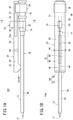
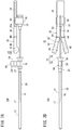
Fig. 1A is a side view of a catheter assembly according to a first embodiment.Fig. 1B is a plan view of the catheter assembly according to the first embodiment. -
Fig. 2 is a cross-sectional view taken along line II-II inFig. 1A . -
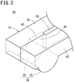
Fig. 3 is a perspective view of a distal end portion of a deflection suppressing member of the catheter assembly according to the first embodiment. -
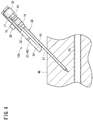
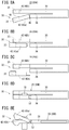
Fig. 4 is a first diagram illustrating a method of using the catheter assembly according to the first embodiment. -
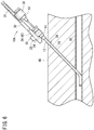
Fig. 5 is a second diagram illustrating a method of using the catheter assembly according to the first embodiment. -
Fig. 6 is a third diagram illustrating a method of using the catheter assembly according to the first embodiment. -
Fig. 7A is a fourth view (side view) illustrating a method of using the catheter assembly according to the first embodiment.Fig. 7B is a plan view of the catheter assembly in the state ofFig. 7A . -
Fig. 8A is a plan view of a deflection suppressing member according to a first modification.Fig. 8B is a plan view of a deflection suppressing member according to a second modification.Fig. 8C is a plan view of a deflection suppressing member according to a third modification.Fig. 8D is a plan view of a deflection suppressing member according to a fourth modification.Fig. 8E is a side view of the deflection suppressing member according to the fourth modification. -
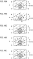
Fig. 9 is a side view of a catheter assembly having a support portion according to another configuration example. -
Fig. 10A is a cross-sectional view of a support portion according to a first configuration example taken along line XA-XA inFig. 9 .Fig. 10B is a cross-sectional view of a support portion according to a second configuration example.Fig. 10C is a cross-sectional view of a support portion according to a third configuration example.Fig. 10D is a cross-sectional view of a support portion according to a fourth configuration example.Fig. 10E is a cross-sectional view of a support portion according to a fifth configuration example. -
Fig. 11A is a side view of the catheter assembly according to the second embodiment.Fig. 11B is a first diagram illustrating a method of using the catheter assembly according to the second embodiment. -
Fig. 12A is a second diagram illustrating a method of using the catheter assembly according to the second embodiment.Fig. 12B is a third diagram illustrating a method of using the catheter assembly according to the second embodiment.Fig. 12C is a fourth diagram illustrating a method of using the catheter assembly according to the second embodiment. -
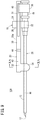
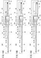
Fig. 13A is a side view of a catheter assembly according to a third embodiment.Fig. 13B is a plan view of a deflection suppressing member of the catheter assembly according to the third embodiment. -
Fig. 14A is a first diagram illustrating a method of using the catheter assembly according to the third embodiment.Fig. 14B is a second diagram illustrating a method of using the catheter assembly according to the third embodiment. -
Fig. 15 is a third diagram illustrating a method of using the catheter assembly according to the third embodiment. -
Fig. 16A is a side view of a first modification of the catheter assembly according to the third embodiment.Fig. 16B is a side view of a second modification of the catheter assembly according to the third embodiment.Fig. 16C is a side view of a third modification of the catheter assembly according to the third embodiment. -
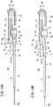
Fig. 17A is a side view of a catheter assembly according to a fourth embodiment.Fig. 17B is a first diagram illustrating a method of using the catheter assembly according to a fourth embodiment. -
Fig. 18A is a second diagram illustrating a method of using the catheter assembly according to the fourth embodiment.Fig. 18B is a third diagram illustrating a method of using the catheter assembly according to the fourth embodiment. - Hereinafter, preferred embodiments of a catheter assembly according to the present invention will be described with reference to the accompanying drawings.
- A
catheter assembly 10A according to a first embodiment illustrated inFigs. 1A and 1B is used for administering an infusion agent (medical solution) to a patient, for example. Thecatheter assembly 10A may be configured as a peripheral venous catheter. Thecatheter assembly 10A may also be configured as a catheter (for example, central venous catheter, PICC, midline catheter) longer than the peripheral venous catheter. Furthermore, thecatheter assembly 10A is not limited to a venous catheter, and may be configured as an arterial catheter such as a peripheral artery catheter. - The
catheter assembly 10A includes acatheter 12, acatheter hub 14 connected to the proximal end side of thecatheter 12, acatheter operating portion 15 attached to thecatheter hub 14, aninner needle 16 removably inserted into thecatheter 12, aneedle hub 18 connected to theinner needle 16, and adeflection suppressing member 20 for suppressing deflection of theinner needle 16 during puncture. - In the use of the
catheter assembly 10A, theneedle hub 18 is grasped by a user (a doctor, a nurse, etc.) for operation, so as to allow its distal end portion to be punctured into theblood vessel 50 of the patient. In an initial state before use (before puncturing the patient), thecatheter assembly 10A has a double-tube structure in which theinner needle 16 is inserted through thecatheter 12, with theinner needle 16 protruding by a predetermined length from the distal end of thecatheter 12. - The
catheter assembly 10A in the initial state is formed by combining a double-tube structure of thecatheter 12 and theinner needle 16, thecatheter hub 14, theneedle hub 18, and thedeflection suppressing member 20 to constitute one assembly and can be handled integrally. - The
catheter 12 is a flexible thin tubular member formed to have a predetermined length. As the constituent material of thecatheter 12, a resin material, particularly, a soft resin material is suitable. The length of thecatheter 12 is not particularly limited, and is appropriately set in accordance with the use, various conditions, or the like. Examples of the setting length of thecatheter 12 are about 20 to 500 mm, about 30 to 400 mm, or about 100 to 300 mm. - The
catheter hub 14 is a hollow member having an inner cavity communicating with the inner cavity of thecatheter 12, and is formed thicker than thecatheter 12. Thecatheter hub 14 is liquid-tightly connected and fixed to the proximal end portion of thecatheter 12. Example of a constituent material of thecatheter hub 14 is a hard resin such as polypropylene. - The
catheter operating portion 15 is an operating portion for performing advancing operation of thecatheter 12, and is attached to thecatheter hub 14. InFig. 1A , thecatheter operating portion 15 includes: a fixedbase portion 22 fixed to thecatheter hub 14; and an extendingportion 24 extending upward from the fixedbase portion 22. An operating element 26 (finger grip portion) for the user to apply own fingers is provided at an extending end of the extendingportion 24. - The
catheter operating portion 15 penetrates a slit 36 (refer toFig. 1B ) described below formed in thedeflection suppressing member 20, and the above-describedoperating element 26 protrudes from anupper surface 20a of thedeflection suppressing member 20. The user can operate thecatheter hub 14 in the axial direction by touching and then grasping or pressing the portion (operating element 26) protruding from thedeflection suppressing member 20, on thecatheter operating portion 15. - As illustrated in
Fig. 2 , an engaging groove 27 (engaging portion) to slidably engage with thedeflection suppressing member 20 in an axial direction is formed on the extendingportion 24, more toward the fixedbase portion 22 side than the operatingelement 26. - Note that the
catheter operating portion 15 may be configured to be removable from thecatheter hub 14. Alternatively, thecatheter operating portion 15 may be formed integrally with thecatheter hub 14. Hereinafter, a member including thecatheter 12, thecatheter hub 14, and thecatheter operating portion 15 will be referred to as a "catheter member 28". - In
Figs. 1A and 1B , theinner needle 16 is a hollow elongated member having asharp needle point 17 at its distal end and having rigidity capable of puncturing patient'sskin 48. In the initial state of thecatheter assembly 10A, theneedle point 17 of theinner needle 16 protrudes from a distal end opening of thecatheter 12 by a predetermined length. In addition, in the initial state, a middle site in the longitudinal direction of theinner needle 16 is inserted into thecatheter hub 14, and the proximal end side of theinner needle 16 is held by theneedle hub 18. - Examples of a constituent material of the
inner needle 16 include: a metal material such as stainless steel; a hard resin; a ceramics material, or the like. Theinner needle 16 may have a solid structure. - Next, the
deflection suppressing member 20 will be described. Thedeflection suppressing member 20 supports theinner needle 16 on more distal end side than thecatheter hub 14 via thecatheter 12 and is supported so as to be displaceable relative to theneedle hub 18 in the axial direction. - Specifically, the
deflection suppressing member 20 includes: abase portion 30 extending along the axial direction of theinner needle 16; a distalend forming portion 32 extending from the distal end of thebase portion 30 in the distal end direction; asupport portion 34 provided at the distalend forming portion 32 and coming in contact with or in the proximity to the outer peripheral surface of thecatheter 12; and a slit 36 (refer toFigs. 1B and3 ) extending along the longitudinal direction of thedeflection suppressing member 20. - The
base portion 30 is formed in a plate shape and is slidably supported in the axial direction by aslide support body 38 fixed to theneedle hub 18. A guide groove 31 (groove portion) extending in the longitudinal direction of thebase portion 30 is formed on each of side surfaces on both sides in the left-right direction (width direction) of thebase portion 30. A portion (proximal end side portion) of theslit 36 is formed in thebase portion 30. Theslit 36 penetrates in the thickness direction of thedeflection suppressing member 20. - As illustrated in
Fig. 2 , a pair ofguide projections 40 protruding inward in the left-right direction is provided on the upper portion of theslide support body 38. Theguide projection 40 is inserted into theguide groove 31. This configuration enables thedeflection suppressing member 20 to move relative to theneedle hub 18 smoothly in the axial direction. It is desirable that the relationship between a length (L1) of theguide groove 31 and an entire length (L2) of thecatheter 12 be L1 > L2/2. With this configuration, thedeflection suppressing member 20 can support more distal end side of thecatheter 12 than a middle portion (center portion in the longitudinal direction), and thedeflection suppressing member 20 can move to more proximal side than the proximal end portion of thecatheter 12 as necessary. - As illustrated in
Fig. 1B , the distalend forming portion 32 includes twoarms 42 juxtaposed in an initial state and is configured to be changeable from a closed state to an open state permitting passage of thecatheter operating portion 15. In the present embodiment, each of thearms 42 is connected to the distal end portion of thebase portion 30 via ahinge portion 44, and is pivotable with respect to thebase portion 30 with thehinge portion 44 as a fulcrum. - Specifically, each of the
arms 42 is pivotable in a direction away from each other about an axis extending in the thickness direction of thedeflection suppressing member 20. Thehinge portion 44 may be a thin portion integrally formed with thebase portion 30 and thearm 42, or may be a fitting structure of an axial portion and a hole portion. - As illustrated in
Fig. 3 , aprotrusion 46 protruding slightly inward is provided on the inner side of the distal end portion of each of thearms 42. In the initial state, theprotrusions 46 are brought into contact with each other, so as to close the distalend forming portion 32. A gap is formed between the twoarms 42, on more proximal end side than theprotrusion 46, and this gap constitutes the other portion (the distal end side portion) of theslit 36. - The
support portion 34 protrudes toward thecatheter 12 side, on a side (lower surface inFig. 1A ) of thedeflection suppressing member 20 facing thecatheter 12. In the initial state, thesupport portion 34 may be in contact with the outer peripheral surface of thecatheter 12 or may be slightly separated from the outer peripheral surface of thecatheter 12. As illustrated inFig. 3 , thesupport portion 34 is formed with twosupport elements 35. Onesupport element 35 is provided on onearm 42. Theother support element 35 is provided on theother arm 42. - Next, functions and effects of the
catheter assembly 10A configured as described above will be described. - In the use of the
catheter assembly 10A, a user (a doctor, a nurse, or the like) serving as a practitioner grasps the needle hub 18 (and its peripheral members as necessary) of thecatheter assembly 10A in the initial state illustrated inFigs. 1A and 1B . Then, as illustrated inFig. 4 , the user punctures the patient'sskin 48 with thecatheter 12 and theinner needle 16 toward a patient'sblood vessel 50. - During this puncture, deflection of the
inner needle 16 is suppressed by thedeflection suppressing member 20. That is, thesupport portion 34 holds thecatheter 12 to enable theinner needle 16 to be supported by thedeflection suppressing member 20 via thecatheter 12 even when theinner needle 16 is going to deflect toward the side opposite to theskin 48 at the time of puncturing. This configuration suppresses the deflection of theinner needle 16 at the time of puncture, enabling stable puncturing. At this time, thesupport portion 34 is in contact with the middle portion of thecatheter 12. - While the
inner needle 16 and thecatheter 12 have not reached theblood vessel 50 in the state ofFig. 4 , if theentire catheter assembly 10A is advanced as it is in order to allow theinner needle 16 and thecatheter 12 to reach theblood vessel 50, thedeflection suppressing member 20 would come into contact with theskin 48. To avoid this, as illustrated inFig. 5 , the user advances the members (theinner needle 16, thecatheter 12, or the like) other than thedeflection suppressing member 20 in thecatheter assembly 10A while holding the position of thedeflection suppressing member 20, thereby puncturing theblood vessel 50 with the distal ends of theinner needle 16 and thecatheter 12. At this time, thecatheter operating portion 15 advances in the slit 36 (refer toFig. 1B ). At this time, thesupport portion 34 retreats with respect to thecatheter 12 while maintaining the state of being in contact with thecatheter 12. - At the time of this advancing operation, deflection of the
inner needle 16 is also suppressed by thedeflection suppressing member 20. That is, while thecatheter assembly 10A moves from the state illustrated inFig. 4 to the state illustrated inFig. 5 , theinner needle 16 is supported, via thecatheter 12, by thedeflection suppressing member 20 moving relative to theneedle hub 18 in the proximal end direction. Consequently, with the use of thecatheter assembly 10A, the deflection of theinner needle 16 at the time of puncturing is suppressed to enable stable puncturing during the period from the start of the puncture into theskin 48 to the completion of the puncture into theblood vessel 50. - After puncturing the
blood vessel 50, the user hooks own finger to thecatheter operating portion 15 protruding upward from thedeflection suppressing member 20 and pushes thecatheter operating portion 15 in the distal end direction while holding the position of thedeflection suppressing member 20. Then, as illustrated inFig. 6 , thecatheter hub 14 and thecatheter 12 connected to thecatheter operating portion 15 move in the distal end direction with respect to theinner needle 16 and theneedle hub 18, increasing the insertion length of thecatheter 12 into theblood vessel 50. - Once the user has inserted the
catheter 12 by a predetermined length into theblood vessel 50, then the user pulls theneedle hub 18 in the proximal end direction with the position of thecatheter member 28 held. Then, theinner needle 16 moves in the proximal end direction within thecatheter member 28, and eventually theinner needle 16 is completely removed from thecatheter member 28. As a result, thecatheter member 28 alone among thecatheter assembly 10A is indwelled on the patient side. - In this manner, during advancing operation of the
catheter 12 with respect to theinner needle 16 in order to insert thecatheter 12 by a predetermined length into theblood vessel 50, or while pulling theneedle hub 18 in the proximal end direction in order to remove theinner needle 16 from thecatheter 12, thecatheter operating portion 15 is detached from thedeflection suppressing member 20 in the distal end direction as illustrated inFigs. 7A and 7B . Specifically, together with the relative movement of thedeflection suppressing member 20 and thecatheter operating portion 15 in the axial direction, thecatheter operating portion 15 pushes the two arms 42 (proximal ends of the protrusions 46) in the distal end direction. With this pushing force, the twoarms 42 expand in the left-right direction, permitting passage of thecatheter operating portion 15. - In this manner, the
deflection suppressing member 20 suppresses the deflection of theinner needle 16 at the time of puncture by supporting theinner needle 16 until completion of the puncture into theblood vessel 50 during the puncture operation. In addition, after the puncture, thedeflection suppressing member 20 opens the distal end forming portion 32 (twoarms 42 in the present embodiment) to prevent interference with thecatheter operating portion 15. - After withdrawing the
inner needle 16 from thecatheter member 28 as described above, the user fixes thecatheter hub 14 to the patient with a dressing material, a tape, or the like. Then, the user connects a connector of an infusion tube (not illustrated) to the proximal end side of thecatheter hub 14, and supplies an infusion agent (medical solution) to the patient from the infusion tube. Note that in a case where thecatheter operating portion 15 is detachable from thecatheter hub 14, thecatheter operating portion 15 may first be removed from thecatheter hub 14 and then thecatheter hub 14 may be fixed to the patient with a dressing material or the like. - As described above, with the
catheter assembly 10A according to the first embodiment, theinner needle 16 is supported by thedeflection suppressing member 20 at the time of puncture, leading to suppression of the deflection of theinner needle 16 at the time of puncture, enabling execution of stable puncture. Therefore, the puncture operation can be performed smoothly. Furthermore, it is possible at the time of puncturing to move theinner needle 16 and thecatheter 12 in the distal end direction while holding the position of thedeflection suppressing member 20. This makes it possible to puncture while supporting theinner needle 16 by thedeflection suppressing member 20 without causing interference between thedeflection suppressing member 20 and theskin 48 of the patient. - With this
catheter assembly 10A, when advancing thecatheter 12 with respect to theinner needle 16, the user can easily perform the advancing operation of thecatheter 12 by operating thecatheter operating portion 15 protruding from thedeflection suppressing member 20. In addition, since the slit 36 (refer toFig. 1B ) is provided in thedeflection suppressing member 20, the advancing operation can be performed without any problem, without hindrance of the advancing movement of thecatheter 12 by thedeflection suppressing member 20. - In the
catheter assembly 10A, thedeflection suppressing member 20 includes a distalend forming portion 32 that enables thecatheter operating portion 15 to be detached from theslit 36. With this configuration, thecatheter operating portion 15 can be detached from thedeflection suppressing member 20 after completion of the advancing operation of thecatheter 12, making it possible to remove theinner needle 16 from thecatheter 12 without any problem. - In the
catheter assembly 10A, thearm 42 is coupled to thebase portion 30 via ahinge portion 44. With this configuration, it is possible to easily form a gap through which thecatheter operating portion 15 can pass at the distal end portion of thedeflection suppressing member 20 by moving thearm 42 with thehinge portion 44 as a fulcrum. In addition, since the twoarms 42 are automatically expanded together with advance of thecatheter operating portion 15, there is no need to perform independent spreading operation, leading to excellent operability. - The
catheter assembly 10A includes the engaging groove 27 (engaging portion) to engage with thedeflection suppressing member 20, leading to suppression of deflection of thedeflection suppressing member 20 itself during the puncture operation. Therefore, it is possible to further effectively suppress the deflection of theinner needle 16 supported by thedeflection suppressing member 20. - Note that while the configuration described above is a case where it is configured to push the two
arms 42 by thecatheter operating portion 15 to open the twoarms 42, it is allowable to configure to push the twoarms 42 by thecatheter hub 14 itself (projection provided on thecatheter hub 14, etc.) to open the twoarms 42. - The two
arms 42 may be configured to be fitted or engaged with each other by a weak fitting force or engaging force so as not to unintentionally open in the initial state, and the twoarms 42 may be configured to be released from the fitting or engaging state when pushed by thecatheter operating portion 15 or thecatheter hub 14, so as to open. - In the
catheter assembly 10A, the configuration for detaching thecatheter operating portion 15 from thedeflection suppressing member 20 is not limited to the above-described configuration. Accordingly, thedeflection suppressing member 20 may be configured like thedeflection suppressing members 20A to 20D illustrated inFigs. 8A to 8E , for example. The similar applies to thecatheter assemblies 10B to 10D according to other embodiments described below. - In the
deflection suppressing member 20A illustrated inFig. 8A , onearm 42a of the twoarms 42 constituting the distalend forming portion 32 is pivotable with respect to thebase portion 30 with thehinge portion 44 as a fulcrum, while theother arm 42b is integrally provided so as not to be pivotable with respect to thebase portion 30. - Even with this configuration, one
arm 42a is expanded when thecatheter operating portion 15 moves relative to thedeflection suppressing member 20A in the distal end direction, making it possible to detach thecatheter operating portion 15 from thedeflection suppressing member 20A. Furthermore, since theprotrusion 46 is not formed on theother arm 42b, thecatheter operating portion 15 can be detached from thedeflection suppressing member 20A without being caught by theother arm 42b. This point is similarly applied to the cases inFigs. 8B to 8E described below. - In the
deflection suppressing member 20B illustrated inFig. 8B , onearm 42a of the twoarms 42 constituting the distalend forming portion 32 is joined, with a weak joining force (fitting force or engaging force), to the distal end of thebase portion 30 in the initial state. However, when a force of a predetermined level or more is applied to the distal end direction, the onearm 42a can be separated from the distal end of thebase portion 30 in the distal end direction. Theother arm 42b is integrally provided so as not to be separable from thebase portion 30. - Even with the configuration of
Fig. 8B , when thecatheter operating portion 15 moves relative to thedeflection suppressing member 20B in the distal end direction, onearm 42a can be shifted in the distal end direction with respect to thebase portion 30 to remove the onearm 42a, making it possible to detach thecatheter operating portion 15 from thedeflection suppressing member 20B. - In the
deflection suppressing member 20C illustrated inFig. 8C , onearm 42a of the twoarms 42 constituting the distalend forming portion 32 is joined to the distal end of thebase portion 30 in the initial state. However, when a force of a predetermined level or more is applied toward an outer side in the width direction (arrangement direction of the two arms 42) of thedeflection suppressing member 20C, the onearm 42a can be separated from the distal end of thebase portion 30 toward the outer side. Theother arm 42b is integrally provided so as not to be separable from thebase portion 30. - Even with the configuration in
Fig. 8C , onearm 42a can be shifted to the outer side in the width direction with respect to thebase portion 30 so as to remove the onearm 42a when thecatheter operating portion 15 moves relative to thedeflection suppressing member 20C in the distal end direction, making it possible to detach thecatheter operating portion 15 from thedeflection suppressing member 20C. Moreover, unlike the configuration ofFig. 8B in which the force is applied in the distal end direction at separation of thearm 42a, this configuration is a case where no force is applied in the distal end direction at separation of thearm 42a, making it possible to avoid unintentional movement of thedeflection suppressing member 20C in the distal end direction. Note that theother arm 42b may be configured to be removable from thebase portion 30 by being shifted in the thickness direction of thedeflection suppressing member 20C with respect to thebase portion 30. - In the
deflection suppressing member 20D illustrated inFig. 8D and Fig. 8E , onearm 42a of the twoarms 42 constituting the distalend forming portion 32 is pivotable with respect to thebase portion 30 having anaxial portion 52 along the width direction of thedeflection suppressing member 20D as a fulcrum. Theother arm 42b is integrally provided so as not to be pivotable from thebase portion 30. Even with this configuration, onearm 42a is rotated upward when thecatheter operating portion 15 moves relative to thedeflection suppressing member 20D in the distal end direction, making it possible to detach thecatheter operating portion 15 from thedeflection suppressing member 20D. - As illustrated in
Fig. 9 , it is allowable in thecatheter assembly 10A to adopt asupport portion 54 configured to surround the outer peripheral surface of the catheter 12 a half or more of the circumferential direction range, in place of thesupport portion 34 that supports theinner needle 16 from one direction alone. With thissupport portion 54, it is possible suppress deflection of theinner needle 16 also in the downward direction and the left-right direction in addition to the upward direction. The similar applies to thecatheter assemblies 10B to 10D according to other embodiments described below. Thesupport portion 54 is configured likesupport portions 54A to 54E respectively illustrated inFigs. 10A to 10E , for example. - The
support portion 54A illustrated inFig. 10A is configured to surround the entire circumference of the outer peripheral surface of thecatheter 12. Asemicircular recess 56 is formed on an inner surface of each of the twosupport elements 55. The tworecesses 56 form a holdinghole 58 penetrating along the axial direction of theinner needle 16. In the initial state, the outer peripheral surface of thecatheter 12 and the inner surface of the holdinghole 58 may be in contact with each other, or may be in proximity to each other via a slight gap. - The
support portion 54B illustrated inFig. 10B is configured to surround the outer peripheral surface of thecatheter 12 so as to expose a portion (a range less than 180°) of the circumferential direction. Anarcuate recess 60 that is less than a semicircle is formed on the inner surface of the twosupport elements 55. The tworecesses 60 form a holdinggroove 62 penetrating along the axial direction of theinner needle 16. With thissupport portion 54B, it is possible to suppress deflection of theinner needle 16 also in the downward direction and the left-right direction in addition to the upward direction, similarly to the case of thesupport portion 54A. - The
support portion 54C illustrated inFig. 10C includes the twosupport elements 55 on which therecess 56 is formed similarly to thesupport portion 54A illustrated inFig. 10A . On the inner surface of therecess 56, agel material 64 is applied as a friction reduction member for reducing frictional resistance (sliding resistance) between the outer peripheral surface of thecatheter 12 and the inner surface of thesupport portion 54C. With the configuration ofFig. 10C , even when a coating (lubricating coat) for reducing the puncture resistance is formed on the outer peripheral surface of thecatheter 12, it is possible to suppress peeling of the lubricant coat at movement of thedeflection suppressing member 20 relative to thecatheter 12 in the axial direction. - The
support portion 54D illustrated inFig. 10D includes the twosupport elements 55 on which therecess 56 is formed similarly to thesupport portion 54A illustrated inFig. 10A . On the inner surface of therecess 56, a plurality of (four inFig. 10D ) freely rotatable spheres 66 (rolling elements) is arranged to be spaced apart from each other in the circumferential direction as a friction reduction member for reducing the frictional resistance between the outer peripheral surface of thecatheter 12 and the inner surface of thesupport portion 54D. Thesespheres 66 are in point contact with the outer peripheral surface of thecatheter 12. With the configuration ofFig. 10D , even when the lubricating coat is formed on the outer peripheral surface of thecatheter 12, it is possible to minimize damage occurring in the lubricating coat during movement of thedeflection suppressing member 20 relative to thecatheter 12 in the axial direction. - The
support portion 54E illustrated inFig. 10E includes the twosupport elements 55 on which therecess 56 is formed similarly to thesupport portion 54A illustrated inFig. 10A . On the inner surface of therecess 56, a plurality of (two inFig. 10E ) freely rotatable cylindrical rollers (rolling elements) 68 is arranged to be spaced apart from each other in the circumferential direction as a friction reduction member for reducing the frictional resistance between the outer peripheral surface of thecatheter 12 and the inner surface of thesupport portion 54E. Thesecylindrical rollers 68 are in point contact with the outer peripheral surface of thecatheter 12. With the configuration ofFig. 10E , even when the lubricating coat is formed on the outer peripheral surface of thecatheter 12, it is possible to minimize damage occurring in the lubricating coat during movement of thedeflection suppressing member 20 relative to thecatheter 12 in the axial direction. - The
catheter assembly 10B according to a second embodiment illustrated inFig. 11A is acatheter assembly 10A to which aguide wire 70 has been added. Theguide wire 70 is a flexible linear member and is inserted into the inner cavity of theinner needle 16 so as to be slidable in the axial direction. Theguide wire 70 is longer than the entire length of theinner needle 16 and thecatheter 12 and is set to a length that can protrude from the distal end of theinner needle 16 by a predetermined length by advancing operation of theguide wire 70. - Moreover, in the
catheter assembly 10B, aguide member 72 that guides theguide wire 70 and generates appropriate movement resistance to theguide wire 70 is attached to the proximal end portion of theneedle hub 18. Theguide member 72 also has a sealing function of preventing blood leakage from the proximal end of theneedle hub 18 at the puncture into the blood vessel using theinner needle 16. Astopper 74 formed thicker than theguide wire 70 is fixed to the proximal end portion of theguide wire 70. - In application of the
catheter assembly 10B, the user punctures into theblood vessel 50 with the distal end portions of theinner needle 16 and thecatheter 12 similarly to the case of thecatheter assembly 10A. With this configuration, as illustrated inFig. 11B , thecatheter assembly 10B shifts to a state in which members other than thedeflection suppressing member 20 have moved relative to thedeflection suppressing member 20 in the distal end direction. Thereafter, theguide wire 70 is used as necessary or in accordance with user's preference. - In a case where the
guide wire 70 is not to be used after the above-described puncture operation, the user operates thecatheter operating portion 15 in the distal end direction while holding the position of theguide wire 70 with respect to theinner needle 16 as illustrated inFig. 12A . With this operation, the user advances thecatheter 12 with respect to theinner needle 16 and inserts the distal end portion of thecatheter 12 into theblood vessel 50 by a predetermined length. The subsequent operation procedure is similar to the case of thecatheter assembly 10A. - In a case where the
guide wire 70 is to be used after the above-described puncture operation, the user moves theguide wire 70 in the distal end direction with respect to theinner needle 16 as illustrated inFig. 12B so as to allow theguide wire 70 to protrude from the distal end of theinner needle 16 by a predetermined length. At this time, thestopper 74 fixed to the proximal end portion of theguide wire 70 comes into contact with theguide member 72, making it possible to prevent excessive insertion of theguide wire 70 into theblood vessel 50. - Next, as illustrated in
Fig. 12C , the user operates thecatheter operating portion 15 in the distal end direction to advance thecatheter 12 with respect to theinner needle 16 so as to insert the distal end portion of thecatheter 12 into theblood vessel 50 by a predetermined length along the outer peripheral surface of theguide wire 70 inserted beforehand. The subsequent operation procedure is similar to the case of thecatheter assembly 10A. - Among the second embodiment, the same or similar functions and effects as those of the first embodiment can be obtained for portions common to the first embodiment.
- In the
catheter assembly 10C according to a third embodiment illustrated inFig. 13A , thestopper 74 in the above-describedcatheter assembly 10B has substantially been replaced with awire operating portion 76. Thewire operating portion 76 includes: awire holding portion 78 connected and fixed to the proximal end portion of theguide wire 70; and amain body portion 80 extending in the distal end direction from the upper end portion of thewire holding portion 78. - The
main body portion 80 faces theupper surface 20a of thedeflection suppressing member 20 in an initial state and is separably connected to thecatheter operating portion 15. Specifically, thedistal end portion 80a of themain body portion 80 and the operatingelement 26 of thecatheter operating portion 15 are releasably engaged or fitted. Accordingly, when a force of a predetermined level or more is applied, the distal end portion of themain body portion 80 and the operatingelement 26 of thecatheter operating portion 15 release the engagement or fitting so as to be separable. Thedistal end 70a of theguide wire 70 is arranged in the vicinity of the distal end inside theinner needle 16 in a state where thedeflection suppressing member 20 and thecatheter operating portion 15 are connected to each other. - As illustrated in
Fig. 13B , the proximal end portion of thedeflection suppressing member 20 includes agroove portion 82 formed to extend along the longitudinal direction of thedeflection suppressing member 20, opening in the proximal direction, and penetrating in the thickness direction of thedeflection suppressing member 20. - In application of the
catheter assembly 10C, the user punctures into theblood vessel 50 with the distal end portions of theinner needle 16 and thecatheter 12 similarly to the case of thecatheter assembly 10A. With this configuration, as illustrated inFig. 14A , thecatheter assembly 10C shifts to a state in which members other than the deflection suppressing member 20 (for example, catheter 12) have moved relative to thedeflection suppressing member 20 in the distal end direction. During puncture operation, thewire operating portion 76 and thecatheter operating portion 15 are engaged or fitted with each other, so as to maintain their relative positions. As a result, the distal end position of theguide wire 70 is held in the vicinity of the distal end inside theinner needle 16. - Next, as illustrated in
Fig. 14B , the user operates thewire operating portion 76 in the distal end direction to move theguide wire 70 in the distal end direction with respect to theinner needle 16. This operation allows theguide wire 70 to protrude from the distal end of theinner needle 16 by a predetermined length. Since the distal end position of theguide wire 70 is positioned in the vicinity of the distal end inside theinner needle 16 in a state immediately before operating thewire operating portion 76 in the distal end direction, theguide wire 70 is promptly inserted into theblood vessel 50 with advance of theguide wire 70. - Furthermore, in a state immediately before operating the
wire operating portion 76 in the distal end direction, the distal end portion of thewire operating portion 76 is in contact with the operatingelement 26 of thecatheter operating portion 15, and both are at substantially the same position. With this configuration, the distal end portion of thewire operating portion 76 can be operated with the same hand as the hand operating the operatingelement 26 of thecatheter operating portion 15, leading to excellent operability. - The advancing operation of the
wire operating portion 76 allows thewire operating portion 76 to enter the inside of thegroove portion 82 formed at the proximal end portion of thedeflection suppressing member 20. With this operation, it is possible to avoid the interference between thewire operating portion 76 and thedeflection suppressing member 20, achieving the advancing operation of thewire operating portion 76 without any problem. - Next, as illustrated in
Fig. 15 , the user operates thecatheter operating portion 15 in the distal end direction to advance thecatheter 12 with respect to theinner needle 16 so as to insert the distal end portion of thecatheter 12 into theblood vessel 50 by a predetermined length along the outer peripheral surface of theguide wire 70 inserted beforehand. The subsequent operation procedure is similar to the case of thecatheter assembly 10A. - As illustrated in
Figs. 16A to 16C , theguide wire 70 exposed to the outside of theneedle hub 18 may be folded back at aguide portion 84 so as to allow theend portion 70b (end portion on the opposite side to the side to be inserted into the blood vessel 50) to be fixed to theneedle hub 18 or to another member fixed to theneedle hub 18. Theguide portion 84 is supported by the proximal end portion of thewire operating portion 76. Theguide portion 84 may be in the form of a rotatable guide roller or may have a non-rotating form. - In
Fig. 16A , theend portion 70b of theguide wire 70 is fixed to theneedle hub 18. InFig. 16B , theend portion 70b of theguide wire 70 is fixed to theguide member 72. InFig. 16C , theend portion 70b of theguide wire 70 is fixed to theslide support body 38. - When the
wire operating portion 76 is operated in the distal end direction with respect to theinner needle 16 and theneedle hub 18 in application of thecatheter assembly 10C illustrated inFigs. 16A to 16C , the guide wire 70 (portion wound around the guide portion 84) is pushed in the distal end direction by the proximal end portion of thewire operating portion 76. With this operation, the portion of theguide wire 70 on the side inserted into the inner needle 16 (portion from the distal end of theguide wire 70 to the guide portion 84) moves in the distal end direction with respect to theinner needle 16. The moving distance of theguide wire 70 with respect to theinner needle 16 at this time is twice the moving distance of thewire operating portion 76. Accordingly, theguide wire 70 can be advanced by a predetermined distance with a shorter operation length. - Among the third embodiment, the same or similar functions and effects as those of the first embodiment can be obtained for portions common to the first embodiment.
- The
catheter assembly 10D according to the fourth embodiment illustrated inFig. 17A includes afolding mechanism 85 that folds theguide wire 70 extending from theneedle hub 18 in the distal end direction. Thefolding mechanism 85 includes: aframe 86 fixed to theguide member 72 and extending in the proximal direction; and aguide portion 88 provided at the proximal end portion of theframe 86. Note that theframe 86 may be fixed to theneedle hub 18 or may be fixed to theslide support body 38. - The
guide portion 88 includes aninner guide 89 and anouter guide 90. Theinner guide 89 may be in the form of a rotatable guide roller or may have a non-rotating form. Theouter guide 90 extends from the proximal end of theframe 86 so as to be curved in an arc shape. Awire operating portion 92 is fixed to theend portion 70b of theguide wire 70. - In application of the
catheter assembly 10D, the user punctures into theblood vessel 50 with the distal end portions of theinner needle 16 and thecatheter 12 similarly to the case of thecatheter assembly 10A. With this configuration, as illustrated inFig. 17B , thecatheter assembly 10D shifts to a state in which members other than the deflection suppressing member 20 (for example, catheter 12) have moved relative to thedeflection suppressing member 20 in the distal end direction. - Next, as illustrated in
Fig. 18A , when the user operates thewire operating portion 92 in the proximal end direction with respect to theinner needle 16 and theneedle hub 18, theguide wire 70 is guided slidably in theguide portion 88, and together with this, a portion of theguide wire 70 on the side inserted into the needle 16 (portion from the distal end of theguide wire 70 to the guide portion 88) moves in the distal end direction with respect to theinner needle 16. This operation allows theguide wire 70 to move in the distal wend direction with respect to theinner needle 16 and allows theguide wire 70 to protrude from the distal end of theinner needle 16 by a predetermined length. - Next, as illustrated in
Fig. 18B , the user operates thecatheter operating portion 15 in the distal end direction to advance thecatheter 12 with respect to theinner needle 16 so as to insert the distal end portion of thecatheter 12 into theblood vessel 50 by a predetermined length along the outer peripheral surface of theguide wire 70 inserted beforehand. The subsequent operation procedure is similar to the case of thecatheter assembly 10A. - Among the fourth embodiment, the same or similar functions and effects as those of the first embodiment can be obtained for portions common to the first embodiment.
- The present invention is not limited to the above-described embodiment, and various modifications are possible without departing from the scope and spirit of the present invention.
Claims (14)
- A catheter assembly (10A to 10D) comprising:a catheter (12);a catheter hub (14) connected to the catheter (12);an inner needle (16) removably inserted into the catheter (12);a needle hub (18) connected to the inner needle (16); anda deflection suppressing member (20, 20A to 20D) that suppresses deflection of the inner needle (16) by supporting the inner needle (16) via the catheter (12) on more toward the distal end side than the catheter hub (14),wherein the deflection suppressing member (20, 20A to 20D) is supported so as to be movable relative to the needle hub (18) in the axial direction.
- The catheter assembly (10A to 10D) according to claim 1,
wherein the deflection suppressing member (20, 20A to 20D) includes at a distal end thereof a support portion (34, 54, 54A to 54E) coming in contact with the catheter (12), and
the support portion (34, 54, 54A to 54E) is movable relative to the catheter (12) while maintaining a state of being in contact with the catheter (12). - The catheter assembly (10A to 10D) according to claim 1 or 2,
wherein the needle hub (18) includes a guide projection (40) ,
the deflection suppressing member (20, 20A to 20D) includes a groove portion (31) to engage with the guide projection (40) of the needle hub (18), and
the length of the groove (31) is longer than 1/2 of the entire length of the catheter (12). - The catheter assembly (10A to 10D) according to any one of claims 1 to 3,
further comprising a catheter operating portion (15) provided on the catheter hub (14),
wherein the deflection suppressing member (20, 20A to 20D) includes a slit (36) permitting relative movement of the catheter operating portion (15) in the axial direction,
the catheter operating portion (15) protrudes from a side opposite to the catheter hub (14) of the deflection suppressing member (20, 20A to 20D) via the slit (36) in the deflection suppressing member (20, 20A to 20D). - The catheter assembly (10A to 10D) according to claim 4,
wherein the deflection suppressing member (20, 20A to 20D) includes: a base portion (30) supported by the needle hub (18) and extending along the axial direction of the inner needle (16); and a distal end forming portion (32) extending from the base portion (30) in the distal end direction and enabling detachment of the catheter operating portion (15) from the slit (36). - The catheter assembly (10A to 10D) according to claim 5,
wherein the distal end forming portion (32) includes two arms (42) that closes a distal end of the slit (36) in an initial state, and
at least one arm (42) of the two arms (42) is movable with respect to the base portion (30). - The catheter assembly (10A to 10D) according to claim 6,
wherein the at least one arm (42) is pivotable with respect to the base portion (30) via a hinge portion (44). - The catheter assembly (10A to 10D) according to claim 6,
wherein the at least one arm (42) is detachable from the base portion (30). - The catheter assembly (10A to 10D) according to any one of claims 4 to 8,
wherein the catheter operating portion (15) includes an engaging portion (27) to engage with the deflection suppressing member (20, 20A to 20D) so as to suppress deflection of the deflection suppressing member (20, 20A to 20D) . - The catheter assembly (10A to 10D) according to any one of claims 1 to 9,
wherein the deflection suppressing member (20, 20A to 20D) includes a support portion (54, 54A to 54E) that is in contact with or in proximity to an outer peripheral surface of the catheter (12) and that surrounds the outer peripheral surface of the catheter (12) by a half or more of a circumferential direction range. - The catheter assembly (10A to 10D) according to claim 10,
wherein a friction reduction member (64, 66, 68) for reducing frictional resistance between the support portion (54C to 54E) and the catheter (12) is provided on an inner peripheral portion of the support portion (54C to 54E). - The catheter assembly (10A to 10D) according to claim 11,
wherein the friction reduction member (64, 66, 68) is a gel material (64) or a rolling element (66, 68) coming in contact with the catheter (12). - The catheter assembly (10A to 10D) according to claim 1,
wherein the inner needle (16) is a hollow member having an inner cavity, and
the catheter assembly (10A to 10D) further comprises a guide wire (70) inserted through the inner cavity so as to be movable relative to the inner needle (16) in the axial direction. - The catheter assembly (10C, 10D) according to claim 13, further comprising:a wire operating portion (76, 92) that supports the guide wire (70); anda catheter operating portion (15) provided on the catheter hub (14),wherein the catheter operating portion (15) includes an operating element (26) protruding from a side opposite to the catheter hub (14) of the deflection suppressing member (20, 20A to 20D), andthe distal end portion of the wire operating portion (76, 92) is in contact with or in proximity to the operating element (26) of the catheter operating portion (15) in an initial state of the catheter assembly (10C, 10D) .
Applications Claiming Priority (2)
| Application Number | Priority Date | Filing Date | Title |
|---|---|---|---|
| JP2016028781 | 2016-02-18 | ||
| PCT/JP2016/079206 WO2017141482A1 (en) | 2016-02-18 | 2016-10-03 | Catheter assembly |
Publications (3)
| Publication Number | Publication Date |
|---|---|
| EP3417902A1 true EP3417902A1 (en) | 2018-12-26 |
| EP3417902A4 EP3417902A4 (en) | 2019-11-20 |
| EP3417902B1 EP3417902B1 (en) | 2024-05-01 |
Family
ID=59625786
Family Applications (1)
| Application Number | Title | Priority Date | Filing Date |
|---|---|---|---|
| EP16890619.6A Active EP3417902B1 (en) | 2016-02-18 | 2016-10-03 | Catheter assembly |
Country Status (5)
| Country | Link |
|---|---|
| US (1) | US11110253B2 (en) |
| EP (1) | EP3417902B1 (en) |
| JP (1) | JP6754784B2 (en) |
| CN (1) | CN108697877B (en) |
| WO (1) | WO2017141482A1 (en) |
Families Citing this family (2)
| Publication number | Priority date | Publication date | Assignee | Title |
|---|---|---|---|---|
| JP7174500B2 (en) | 2018-11-09 | 2022-11-17 | ノースウォード・ベンチャーズ・エルエルシー | Catheter system and method for introducing an intravenous catheter into a patient |
| WO2024015330A1 (en) * | 2022-07-11 | 2024-01-18 | Boston Scientific Scimed, Inc. | Introducer lock apparatus |
Family Cites Families (15)
| Publication number | Priority date | Publication date | Assignee | Title |
|---|---|---|---|---|
| US5403283A (en) * | 1993-10-28 | 1995-04-04 | Luther Medical Products, Inc. | Percutaneous port catheter assembly and method of use |
| US5599305A (en) * | 1994-10-24 | 1997-02-04 | Cardiovascular Concepts, Inc. | Large-diameter introducer sheath having hemostasis valve and removable steering mechanism |
| DE60226954D1 (en) * | 2001-03-14 | 2008-07-17 | Tyco Healthcare | Protective device for medical needles |
| US6652486B2 (en) | 2001-09-27 | 2003-11-25 | Medex, Inc. | Safety catheter |
| JPWO2007132732A1 (en) * | 2006-05-17 | 2009-09-24 | テルモ株式会社 | Indwelling needle assembly |
| US8043268B1 (en) * | 2008-07-22 | 2011-10-25 | Marks Lloyd A | Safety needle and method of using same |
| EP2229975B1 (en) * | 2009-03-20 | 2013-11-13 | Tradinco AB | Inserter assembly for a peripheral catheter with a plaster member, method of configuring the inserter assembly with the peripheral catheter |
| WO2011118643A1 (en) * | 2010-03-26 | 2011-09-29 | テルモ株式会社 | Indwelling needle assembly |
| CN113350663B (en) * | 2013-03-01 | 2022-12-20 | C·R·巴德股份有限公司 | Guidewire extension system for catheter placement device |
| JP6138921B2 (en) * | 2013-04-01 | 2017-05-31 | テルモ株式会社 | Catheter assembly |
| WO2014165783A1 (en) * | 2013-04-05 | 2014-10-09 | University Of Iowa Research Foundation | Catheter assembly with segmented stabilization system |
| CN108939205B (en) * | 2013-06-12 | 2021-03-09 | 泰尔茂株式会社 | Catheter assembly |
| US10918837B2 (en) * | 2013-12-04 | 2021-02-16 | B. Braun Melsungen Ag | Safety needle assemblies and related methods |
| JP6406714B2 (en) * | 2014-01-29 | 2018-10-17 | テルモ株式会社 | Catheter assembly |
| WO2016020923A2 (en) * | 2014-08-05 | 2016-02-11 | Bullpup Scientific Ltd. | Method and apparatus for inserting a catheter tube |
-
2016
- 2016-10-03 CN CN201680082073.7A patent/CN108697877B/en active Active
- 2016-10-03 JP JP2017567944A patent/JP6754784B2/en active Active
- 2016-10-03 WO PCT/JP2016/079206 patent/WO2017141482A1/en active Application Filing
- 2016-10-03 EP EP16890619.6A patent/EP3417902B1/en active Active
-
2018
- 2018-08-14 US US16/103,526 patent/US11110253B2/en active Active
Also Published As
| Publication number | Publication date |
|---|---|
| CN108697877A (en) | 2018-10-23 |
| EP3417902A4 (en) | 2019-11-20 |
| CN108697877B (en) | 2021-12-28 |
| EP3417902B1 (en) | 2024-05-01 |
| JP6754784B2 (en) | 2020-09-16 |
| WO2017141482A1 (en) | 2017-08-24 |
| US20180369540A1 (en) | 2018-12-27 |
| JPWO2017141482A1 (en) | 2018-12-06 |
| US11110253B2 (en) | 2021-09-07 |
Similar Documents
| Publication | Publication Date | Title |
|---|---|---|
| JP6721735B2 (en) | Catheter assembly | |
| JP6966592B2 (en) | Catheter assembly | |
| JP7045417B2 (en) | Catheter assembly | |
| KR102560266B1 (en) | Mid-Line Catheter Placement Device | |
| EP3077034B1 (en) | Safety needle assemblies and related methods | |
| US20220193376A1 (en) | Optimized Structural Support in Catheter Insertion Systems | |
| JP2023536280A (en) | Two-piece rapid-entry central venous catheter, introducer for two-piece rapid-entry central venous catheter, and method thereof | |
| JP6886775B2 (en) | Catheter assembly | |
| JP2018507024A (en) | Releasable catheter hub retainer | |
| EP3275499B1 (en) | Catheter assembly | |
| US11110253B2 (en) | Catheter assembly | |
| US11684756B2 (en) | Catheter assembly | |
| JP2001299928A (en) | Self-dulling type safety catheter | |
| US11383031B2 (en) | Catheter assembly | |
| KR102120615B1 (en) | Easy catheter assembly | |
| US20220387761A1 (en) | Catheter assembly | |
| JP7183252B2 (en) | catheter assembly | |
| US20210205588A1 (en) | Catheter assembly | |
| US20160015942A1 (en) | Catheter assembly | |
| JP2007167243A (en) | Indwelling needle apparatus |
Legal Events
| Date | Code | Title | Description |
|---|---|---|---|
| STAA | Information on the status of an ep patent application or granted ep patent |
Free format text: STATUS: THE INTERNATIONAL PUBLICATION HAS BEEN MADE |
|
| PUAI | Public reference made under article 153(3) epc to a published international application that has entered the european phase |
Free format text: ORIGINAL CODE: 0009012 |
|
| STAA | Information on the status of an ep patent application or granted ep patent |
Free format text: STATUS: REQUEST FOR EXAMINATION WAS MADE |
|
| 17P | Request for examination filed |
Effective date: 20180814 |
|
| AK | Designated contracting states |
Kind code of ref document: A1 Designated state(s): AL AT BE BG CH CY CZ DE DK EE ES FI FR GB GR HR HU IE IS IT LI LT LU LV MC MK MT NL NO PL PT RO RS SE SI SK SM TR |
|
| AX | Request for extension of the european patent |
Extension state: BA ME |
|
| STAA | Information on the status of an ep patent application or granted ep patent |
Free format text: STATUS: REQUEST FOR EXAMINATION WAS MADE |
|
| DAV | Request for validation of the european patent (deleted) | ||
| DAX | Request for extension of the european patent (deleted) | ||
| A4 | Supplementary search report drawn up and despatched |
Effective date: 20191021 |
|
| RIC1 | Information provided on ipc code assigned before grant |
Ipc: A61M 25/06 20060101AFI20191015BHEP Ipc: A61M 25/00 20060101ALI20191015BHEP Ipc: A61M 25/09 20060101ALI20191015BHEP Ipc: A61M 25/02 20060101ALN20191015BHEP |
|
| STAA | Information on the status of an ep patent application or granted ep patent |
Free format text: STATUS: EXAMINATION IS IN PROGRESS |
|
| 17Q | First examination report despatched |
Effective date: 20230704 |
|
| GRAP | Despatch of communication of intention to grant a patent |
Free format text: ORIGINAL CODE: EPIDOSNIGR1 |
|
| STAA | Information on the status of an ep patent application or granted ep patent |
Free format text: STATUS: GRANT OF PATENT IS INTENDED |
|
| INTG | Intention to grant announced |
Effective date: 20231124 |
|
| GRAS | Grant fee paid |
Free format text: ORIGINAL CODE: EPIDOSNIGR3 |
|
| GRAA | (expected) grant |
Free format text: ORIGINAL CODE: 0009210 |
|
| STAA | Information on the status of an ep patent application or granted ep patent |
Free format text: STATUS: THE PATENT HAS BEEN GRANTED |