EP3417689B1 - Landwirtschaftliche pneumatische verteilmaschine - Google Patents
Landwirtschaftliche pneumatische verteilmaschine Download PDFInfo
- Publication number
- EP3417689B1 EP3417689B1 EP18401048.6A EP18401048A EP3417689B1 EP 3417689 B1 EP3417689 B1 EP 3417689B1 EP 18401048 A EP18401048 A EP 18401048A EP 3417689 B1 EP3417689 B1 EP 3417689B1
- Authority
- EP
- European Patent Office
- Prior art keywords
- line
- dispensing
- distributed
- distribution
- delivery
- Prior art date
- Legal status (The legal status is an assumption and is not a legal conclusion. Google has not performed a legal analysis and makes no representation as to the accuracy of the status listed.)
- Active
Links
Images




Classifications
-
- A—HUMAN NECESSITIES
- A01—AGRICULTURE; FORESTRY; ANIMAL HUSBANDRY; HUNTING; TRAPPING; FISHING
- A01C—PLANTING; SOWING; FERTILISING
- A01C7/00—Sowing
- A01C7/08—Broadcast seeders; Seeders depositing seeds in rows
- A01C7/081—Seeders depositing seeds in rows using pneumatic means
- A01C7/084—Pneumatic distribution heads for seeders
-
- A—HUMAN NECESSITIES
- A01—AGRICULTURE; FORESTRY; ANIMAL HUSBANDRY; HUNTING; TRAPPING; FISHING
- A01C—PLANTING; SOWING; FERTILISING
- A01C7/00—Sowing
- A01C7/08—Broadcast seeders; Seeders depositing seeds in rows
- A01C7/10—Devices for adjusting the seed-box ; Regulation of machines for depositing quantities at intervals
- A01C7/102—Regulating or controlling the seed rate
-
- A—HUMAN NECESSITIES
- A01—AGRICULTURE; FORESTRY; ANIMAL HUSBANDRY; HUNTING; TRAPPING; FISHING
- A01C—PLANTING; SOWING; FERTILISING
- A01C7/00—Sowing
- A01C7/08—Broadcast seeders; Seeders depositing seeds in rows
- A01C7/088—Sectional seeding
Definitions
- the invention relates to an agricultural pneumatic distribution machine according to the preamble of claim 1.
- the distribution characteristic is adapted, for example, by means of a segment or single-row shutdown, in which individual seed elements are temporarily not supplied with seed and / or fertilizer.
- the spreading elements can be configured, for example, as coulters or fertilizer coulters.
- Corresponding agricultural pneumatic distribution machines can have a control system which is set up to control a metering element which is connected to a distribution head via a delivery line.
- the distributor head comprises several outlet openings, which are connected to blockable discharge lines. So that the application rate of the individual application elements on field wedges or in the area of the headlands can be kept constant, the amount of material to be distributed conveyed to the distributor head is adjusted accordingly if the distribution characteristic is changed by a segment and / or individual row shutdown.
- the object underlying the invention is therefore to improve the spreading of granular material by means of an agricultural pneumatic distribution machine on field wedges and in the area of headlands.
- the object is achieved by an agricultural pneumatic distribution machine of the type mentioned at the outset, in that the control system is set up to set the metering element based on the advance speed of the distributor machine, a conveying time of the material to be distributed from the metering element to the distributor head and a conveying time of the material to be distributed from the distributor head to control the dispensing elements in such a way that the currently required total amount of the material to be dispensed is at the distributor head at all times, with the ascertained necessary total amount of the material to be dispensed circulating in the return area at all times and, if at least one previously blocked dispensing line is released, a necessary one without delay Subset of the corresponding application line is supplied.
- the invention makes use of the knowledge that, on the basis of the advance speed of the distributor and the duration of the material to be distributed from the metering element to the distributor head, the amount of material conveyed by the metering element can be adjusted before the blockage or release of individual discharge lines, so that When the individual delivery lines are blocked or released, the appropriate quantity of material to be distributed is available in the distributor head.
- the distribution head to the Application elements block or release individual application lines in good time before reaching the field section, which requires an adjustment of the distribution characteristic, so that when the field section is reached, the intended adjustment of the distribution characteristic takes place.
- the air-material mixture preferably remains in a feed area when a discharge line is blocked by means of a switchover element, the feed area comprising at least one end area of the delivery line and the distributor head.
- the distribution machine preferably comprises at least one storage container for storing the at least one material to be distributed, the dispensing element being assigned to the storage container, which feeds the material to be distributed in adjustable amounts into the pneumatically actuated conveying line, in which the material to be distributed as air-material Mixture is promoted.
- the outlet openings are arranged along the circumference of the distributor head, preferably evenly spaced from one another.
- the required total amount of the material to be applied can be an amount of material per unit of area, distance or time.
- the control system controls the metering element in such a way that the quantity of material to be distributed fed into the conveying line corresponds to the total quantity of material to be distributed that is necessary at the distributor head.
- the total amount of material to be distributed required at the distributor head preferably behaves with respect to the necessary total amount of material to be distributed, which is required if none of the discharge lines is blocked, and the number of non-blocked discharge lines with respect to the total number of all discharge lines. In this way, when individual application lines are blocked or released as part of a segment or single-row shutdown, there is always a quantity of material to be distributed in the distributor head which is adapted to the number of blocked or released application lines.
- the control system comprises a storage unit, at least one detection device and / or an evaluation unit.
- the evaluation unit is set up to determine, on the basis of data stored in the storage unit and / or recorded by the at least one detection device, application parameters which determine at least a currently required total amount of the material to be distributed, a duration of delivery of the material to be distributed Dosing element to the distributor head and a duration of conveyance of the material to be distributed from the distributor head to the dispensing elements.
- the data which are stored on the storage unit and / or are recorded by the at least one detection device can include, for example, application information, flow velocities and / or the state of the switchover elements.
- the application information can include, for example, application cards.
- the flow rate of the material to be distributed between the metering element and the distributor head and between the distributor head and the dispensing elements is preferably recorded at one or more points.
- the line lengths between the metering element and the distributor head and between the distributor head and the application elements are also taken into account.
- the line lengths taken into account between the metering element and the distributor head and / or between the distributor head and the dispensing elements can correspond to the actual line lengths or average line lengths, which differ slightly from the actual line lengths.
- a distribution machine is preferred, in which the switching element can be moved between an application position that releases the application line and a return position blocking the application line based on the determined application parameters by means of an actuating element that can be actuated by the control system, preferably automatically.
- the actuating element preferably comprises a bistable rotary magnet. The actuation of a switching element by means of a bistable rotary magnet allows the Realization of extremely short switching times so that the application lines can be blocked or released with a high level of precision.
- the switching element is preferably formed from a metal or a metal alloy and articulated in such a way that the switching element can be brought into at least two rotational angle positions by actuating the actuating element.
- the switchover element In a first angle of rotation position, the switchover element blocks the discharge line, the switchover element in the first angle of rotation position preferably releasing the return line. In a second angle of rotation position, the switchover element releases the application line, the switchover element preferably blocking the return line in the second angle of rotation position.
- At least some outlet openings are each pneumatically connected to the delivery line via a return line
- the return lines each have a branch which is connected to a bypass line which opens into the associated discharge line.
- An air flow to the dispensing elements can be maintained via the bypass line, even if the switchover element is in the return position blocking the dispensing line. In this way, it can be prevented that the blocking of the discharge lines causes the pneumatic conveying of the material to be distributed to the distributor head to break down due to an excessively high counterpressure which is due to the air flows returned and / or backed up in the delivery line. Without the bypass line, the static pressure in the delivery line would increase with an increasing number of blocked discharge lines.
- the delivery of the material to be distributed breaks down in the direction of the distributor head.
- the bypass line separates at least part of the airflow from the material to be distributed and forwards it to the dispensing elements.
- a further advantage that results from this is that due to the continuous air delivery to the dispensing elements, the material to be distributed remaining in the dispensing lines continues to be distributed to the dispensing elements is promoted, although the switching element is in the return position blocking the discharge line. This prevents the material to be distributed remaining in the dispensing lines from rolling through the dispensing line to the dispensing elements due to the force of gravity and resulting in carry-over of material.
- a distribution machine in which air of the air-material mixture is fed to the discharge line via the bypass line in the return position of the switching element.
- the distributor machine is preferably designed such that material to be distributed can also enter the bypass line.
- the bypass line is preferably designed such that material to be distributed that has entered the bypass line is diverted back into the return line within the bypass line.
- Part of the air of the air-material mixture flowing into the bypass line is preferably passed through the bypass line to the dispensing elements. The rest of the air is fed back into the return line with the material of the air-material mixture flowing into the bypass line.
- about two thirds of the air-material mixture directed by the switching element into the return line flow into the bypass line, with about a third of the air-material mixture directed from the switching element into the return line flowing past the bypass line in the direction of the Delivery line flows.
- the distribution machine according to the invention is further advantageously developed in that the delivery line has a nozzle-like constriction.
- the return lines open, preferably directly, in the conveying direction behind the nozzle-like constriction in the conveying line.
- the nozzle-like constriction of the delivery line is preferably designed to prevent the material to be distributed flowing through the delivery line from entering the return lines connected to the delivery line. This is achieved in that the nozzle-like constriction of the delivery line exerts a suction effect, the suction effect guiding the material to be distributed past the openings to the return lines in the direction of the distributor head.
- the nozzle-like constriction of the delivery line creates an increased flow velocity in the delivery line, so that the resulting suction also accelerates the material to be distributed flowing from the return lines into the delivery line in the direction of the distributor head.
- a distribution machine in which several adjacent return lines each open into a collecting element and the collecting elements are connected to the delivery line.
- the collecting elements are preferably connected to the delivery line by means of collecting lines.
- the collecting lines open, preferably directly, in the conveying direction behind the nozzle-like constriction in the conveying line.
- the nozzle-like constriction of the delivery line is preferably designed to prevent the material to be distributed flowing through the delivery line from entering the collecting lines connected to the delivery line.
- a feed area comprises at least the end area of the delivery line, the distributor head and the return lines, wherein the returned material can circulate within the feed area.
- the fact that the returned material can circulate within the return area means that a uniform material flow is immediately available when the discharge lines are released.
- the ascertained necessary total amount of the material to be discharged circulates in the return area at all times and when at least one previously blocked discharge line is released, a necessary part of the corresponding discharge line is fed without delay.
- the necessary total quantity is the sum of all necessary partial quantities and is based on the requirements regarding quantity, position and determined by the evaluation unit
- the necessary subset of a dispensing element can also be zero.
- a distribution machine is advantageous, in which the actuation of the actuating elements that bring the changeover elements is additionally based individually on the duration of delivery between the distributor head and the respective dispensing element and is timed in such a way that the necessary partial quantity is available at any time on the corresponding dispensing element without delay.
- the Fig. 1 shows an agricultural pneumatic spreading machine 10 designed as a pneumatic seed drill for distributing granular material, namely seed.
- the distribution machine 10 comprises a frame structure 12, on which a storage container 14 is arranged.
- the storage container 14 is set up to store the granular material to be distributed.
- the storage container 14 is connected to a delivery line 20 via a metering element 16, the metered granular material being transported to the delivery line 20 by means of a delivery blower 18.
- the metering device 16 is set up to feed the material to be distributed in adjustable amounts into the pneumatically actuated delivery line 20, the material to be distributed being conveyed in the delivery line 20 as an air-material mixture.
- the conveying fan 18 is driven, for example, by a hydraulic motor and causes sufficient pressure to convey the granular material to be distributed through the conveying line 20 to a distributor head 22.
- the distributor head 22 has a plurality of outlet openings.
- the outlet openings are evenly distributed along the circumference of the distributor head 22, so that adjacent outlet openings are each arranged equidistantly from one another.
- Each outlet opening is connected pneumatically via a discharge line (hidden) to a discharge element 24 designed as a coulter.
- the spreading elements 24 are fastened to a support frame 26 and each set up to deposit the granular material to be distributed in a furrow of the arable soil.
- a roller 28 In the direction of travel FR in front of the spreading elements 24, a roller 28 is arranged, which is designed as a wedge ring roller and is set up to reconsolidate the previously worked arable soil.
- Depth guide rollers 30 are arranged behind the dispensing elements 24 in the direction of travel FR, a depth guide roller 30 being assigned to each dispensing element 24. The placement depth of the granular material to be distributed can be adjusted by means of the depth guide rollers 30.
- weeder 32 In the direction of travel FR, behind the depth control rollers 30, weeder 32 are also arranged, which are set up to cover the deposited granular material with an adjustable intensity with loose earth.
- the harrow 32 shown is designed in a tine design, but alternatively roller harrow can also be used.
- the agricultural pneumatic distribution machine 10 has two track markers 34a, 34b, each of which is set up to produce a marking on the field soil.
- the markings show the adjacent lane.
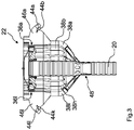
- the Fig. 2 and the Fig. 3 show the distributor head 22 in the Fig. 1 Distribution machine 10 shown, the outlet openings 36a, 36l of the distributor head 22 are each connected to a feedback device 46a, 46l.
- the return devices 46a, 46l each comprise a section of a discharge line 44a-44l, which pneumatically connect the distributor head 22 to the discharge elements. Furthermore, the return devices 46a, 46l each comprise a section of a return line 38a-38l, which pneumatically connect the distributor head 22 to the delivery line 20.
- the discharge lines 44a-44l and return lines 38a-38l are via switching elements 60 (see Fig. 4 ) can be blocked and released in the return devices 46a, 46l.
- the delivery line 20 has a nozzle-like constriction 48.
- the collecting lines 42a, 42b open directly in the conveying direction behind the nozzle-like constriction 48 into the conveyor line 20.
- the nozzle-like constriction 48 prevents material from entering the return lines 38a-38l via the collecting lines 42a, 42b and the collecting elements 40a, 40b and the collecting elements 40a, 40b .
- the granular material to be distributed can be supplied to the discharge elements 24 via the discharge lines 44a-44l. Via the return lines 38a-38l the granular material to be distributed can be fed back into the delivery line 20.
- a feed area includes an end area of the delivery line 20, the manifold 22 and the return lines 38a-38l, wherein the returned material can circulate within the feed area.
- the discharge lines 44a-44l and return lines 38a-38l can be specifically blocked and released and the metering element can be controlled, the control being carried out in such a way that a determined necessary total amount of the material to be discharged circulates in the return area at all times and at least one when released Previously blocked discharge line 44a-44l is fed a necessary subset of the corresponding discharge line 44a-44l without delay.
- the Fig. 4 shows an example of a feedback device 46, the feedback devices 46a, 46l of those shown in FIGS 1 to 3 Distributor 10 shown, for example, according to the in Fig. 4 feedback device 46 can be formed.
- the section of the return line 38 located within the return device 46 has a branch which is connected to a bypass line 50.
- the bypass line 50 opens into the section of the discharge line 44 located in the return device 46.
- the return line 38 has a nozzle-like constriction 62, which prevents material from entering the bypass line 50.
- the nozzle-like constriction 62 creates a suction effect, so that material is returned from the return line 38 into the delivery line (not shown).
- a switch 58 with a switching element 60 is arranged within the return device 46, by means of which the discharge line 44 can be blocked, so that the entry of an air-material mixture into the discharge line 44 is prevented.
- the switching element 60 can be actuated by means of an actuatable actuating element 64 between a dispensing position which releases the dispensing line 44 and blocks the return line and a dispensing position the discharge line 44 blocking and the return line releasing return position are brought.
- the actuating element 64 comprises a bistable rotary magnet which is set up to cause the switching element 60 to rotate in the direction of rotation D in order to move the switching element 60 between the deployed position and the return position.
- the actuating element 64 is controlled automatically via the control system 66.
- the actuation of the actuating element 64 that brings the switching element 60 is additionally based individually on the duration of delivery between the distributor head 22 and the dispensing element 24 and is carried out in such a way that the necessary partial quantity is available at any time on the corresponding dispensing element 24.
- the air-material mixture flowing into the bypass line 50 is directed in the direction of the deflection section 54, which is arranged in the bypass line 50 and is designed as a web direct flow path to the discharge line 44 is arranged and causes a deflection of the air-material mixture.
- a separation edge 56 adjoins the deflection section 54, which causes a stall and deflects a portion of the air of the air-material mixture in the direction of the discharge line 44. The remaining air of the air-material mixture and the material of the air-material mixture are again led out of the bypass line 50 and fed to the delivery line 20.
- the control system 66 is also set up to control the metering element 16 of the associated distribution machine 10, the control system 66 being set up to set the metering element 16 based on the advance speed of the distribution machine 10, a conveying time of the material to be distributed from the metering element 16 to the distributor head 22 and a conveying time of the material to be distributed from the distributor head 22 to the dispensing elements 24, in such a way that the total amount of the material to be dispensed at the distributor head 22 is present at all times in advance.
- the control system 66 comprises a storage unit 68, a detection device 70 and an evaluation unit 72.
- the evaluation unit 72 is set up to apply application parameters on the basis of data stored in the storage unit 68 or on the basis of data which are recorded by the detection device 70 to determine which comprise a currently required total amount of the material to be distributed, a conveying time of the material to be distributed from the metering element 16 to the distributor head 22 and a conveying duration of the material to be distributed from the distributor head 22 to the dispensing elements 24.
- the control system 66 controls the metering element 16 in such a way that the amount of material to be distributed fed into the conveying line 20 corresponds to the total amount of material to be distributed required at the distributor head 22.
- the total amount of material to be distributed required at the distributor head 22 is related to the total amount of material to be distributed, which is required if none of the discharge lines 44 is blocked, as is the number of the not blocked application lines 44 with respect to the total number of all application lines 44.
- the Fig. 5 shows a distribution process, for example with the in the 1 to 3 shown distributor 10 can be implemented.
- the distribution process relates to the spreading of seeds on a field F, the distribution characteristics of the agricultural pneumatic distribution machine in the area of the headlands VG being adapted.
- the distributor moves in the direction of travel FR. So that the most exact possible seed placement at the field boundary and in the area of the headland VG can be implemented, the metering of the seeds is carried out by the metering element 16 and the release and blocking of the application lines 44 by the switching elements 60 depending on the advance speed of the distributor machine 10, the duration of the delivery Seeds from the metering element 16 to the distributor head 22 and the duration of delivery of the seeds from the distributor head 22 to the spreading elements 24.
- the metering of the seed is started by the metering member 16 at level 78a. After the end of the conveying period of the seed from the metering member 16 to the distributor head 22, all the application lines 44 are released at the level 82a, so that after the duration of the conveyance of the seed from the distributor head 22 to the dispensing elements 24 at level 74a, the seed placement begins.
- the metering of the seed by the metering member 16 takes place taking into account the forward speed of the distribution machine 10, so that the seed placement begins at the field edge.
- the metering of the seed is gradually reduced by the metering member 16 in four time-spaced processes by 25% of the total spread rate.
- the spreading lines 44 are blocked in steps 84 in four time-spaced processes by 25% of the total number of spreading lines 44 at level 84a, firstly the spreading lines 44 which are connected to the are blocked dispensing elements 24 arranged on the right side of distribution machine 10 are connected and Finally, the discharge lines 44 are blocked, which are connected to the discharge elements 24 arranged on the left side of the distributor 10.
- the dosing of the seed by the dosing member 16 is reduced taking into account the advancing speed of the distributing machine 10, so that the seed placement ends as precisely as possible on the inclined edge to the headland VG. It should be taken into account here that the distribution machine 10 maintains an at least approximately constant advance speed at least from the height 86a due to the approaching switching process.
- the metering of the seeds by the metering member 16 is gradually increased in steps of four by 25% of the total spread rate at four times at level 78b.
- the discharge lines 44 are released in stages at four times in intervals of 25% of the total number of the discharge lines 44 in four time-spaced operations, with the discharge lines 44 which are connected to the first being released dispensing elements 24 arranged on the right side of the distributor 10 are connected, and finally the discharge lines 44 are connected, which are connected to the dispensing elements 24 arranged on the left side of the distributor 10.
- the seed placement After the conveying time of the seed from the distributor head 22 to the dispensing elements 24, the seed placement also begins at level 74b in four stages.
- the metering of the seed by the metering element 16 is increased taking into account the advancing speed of the distributing machine 10, so that the seed placement begins as precisely as possible on the inclined edge to the headland VG.
- the metering of the seeds is then interrupted by the metering element 16 at level 80b. After the end of the conveying period of the seed from the metering member 16 to the distributor head 22, all at level 84b Discharge lines 44 blocked. After the conveying time of the seed from the distributor head 22 to the dispensing elements 24, the seed placement ends at the height 76b.
- the metering member 16 interrupts the metering of the seed, taking into account the forward speed of the distributing machine 10, so that the seed placement ends as precisely as possible at the field boundary. It should be taken into account here that the distributor machine 10 maintains an at least approximately constant advance speed at least from height 86b due to the approaching switching process.
- the steps described are repeated in the following, so that the seed placement begins at the heights 74c-74g and ends at the heights 76c-76g, the dosage is increased at the heights 78c-78g and reduced to the heights 80c-80g and the application lines 44 are opened the heights 82c-82g released and blocked at the heights 84c-84g. It must be taken into account in each case that the distribution machine 10 maintains an at least approximately constant advance speed at least from heights 86c-86g due to the approaching switching process.
- the metering of the seed by the metering member 16 is gradually reduced or increased in each case in four time-spaced operations by 25% of the total application quantity, with the application lines 44 also being gradually blocked in four time-spaced operations by 25% of the total number of application lines 44 or be released.
- the metering of the seed by the metering element 16 can also be gradually reduced or increased in a different number of time-spaced operations, with the application lines 44 then also being blocked or released in stages in the other number of time-spaced operations.
- the maximum number of stages in which the total application quantity can be reduced or increased and the application lines 44 can be blocked or released corresponds to the number of blocking application lines 44 of the distribution machine 10.
- the steps do not have to be spaced apart in time. Depending on the contour of the surface to be machined, two or more stages can also switch simultaneously. These steps do not have to correspond to adjacent application elements 24.
Landscapes
- Life Sciences & Earth Sciences (AREA)
- Soil Sciences (AREA)
- Environmental Sciences (AREA)
- Fertilizing (AREA)
- Sowing (AREA)
Description
- Die Erfindung betrifft eine landwirtschaftliche pneumatische Verteilmaschine nach dem Oberbegriff des Patentanspruchs 1.
- Beim Ausbringen von Saatgut und/oder Dünger besteht an Feldkeilen oder im Bereich des Vorgewendes regelmäßig die Notwendigkeit, die Verteilcharakteristik der eingesetzten landwirtschaftlichen pneumatischen Verteilmaschine anzupassen, damit Säfenster und Überlappungen effektiv vermieden werden können.
- Die Anpassung der Verteilcharakteristik erfolgt beispielsweise durch eine Segment- oder Einzelreihenabschaltung, bei welcher einzelnen Ausbringelementen temporär kein Saatgut und/oder Dünger zugeführt wird. Die Ausbringelemente können dabei beispielsweise als Säschare oder Düngerschare ausgebildet sein.
- Entsprechende landwirtschaftliche pneumatische Verteilmaschinen können ein Steuersystem aufweisen, welches dazu eingerichtet ist, ein Dosierorgan zu steuern, welches über eine Förderleitung mit einem Verteilerkopf verbunden ist. Der Verteilerkopf umfasst dabei mehrere Ausgangsöffnungen, welche mit blockierbaren Ausbringleitungen verbunden sind. Damit die Ausbringrate der einzelnen Ausbringelemente an Feldkeilen oder im Bereich des Vorgewendes konstant gehalten werden kann, wird die zu dem Verteilerkopf geförderte Menge an zu verteilendem Material entsprechend angepasst, wenn die Verteilcharakteristik durch eine Segment- und/oder Einzelreihenabschaltung verändert wird.
- Aus der Druckschrift
DE 40 04 685 C3 ist beispielsweise eine landwirtschaftliche Maschine zum Verteilen von Granulatmaterial bekannt, bei welcher der Strom von Granulatmaterial von einem Vorratsbehälter zu dem Verteilerkopf in Proportion zu der Anzahl der abgesperrten Ausleger reduziert wird, um eine gleichförmige Ausbringrate durch die verbleibenden Ausleger sicherzustellen. - Andere landwirtschaftliche Verteilmaschinen sind außerdem aus den Druckschriften
WO 2017/055266 A1 undUS 2016/219781 A1 bekannt. - Durch die zeitliche Verzögerung des Materialstroms von dem Dosierorgan bis zu dem Verteilerkopf ist eine präzise und bedarfsgerechte Reduzierung der Materialmenge während der einer Segment- oder Einzelreihenabschaltung bisher nicht möglich. Ferner steht durch die zeitliche Verzögerung des Materialstroms von dem Dosierorgan bis zu dem Verteilerkopf bei Arbeitsbeginn am Vorgewende nicht sofort ausreichend Material zur Verfügung, sodass im Bereich des Vorgewendes eine homogene Ausbringung des zu verteilenden Materials bisher nicht möglich ist.
- Die der Erfindung zugrunde liegende Aufgabe besteht somit darin, die Ausbringung von körnigem Material mittels einer landwirtschaftlichen pneumatischen Verteilmaschine an Feldkeilen und im Bereich von Vorgewenden zu verbessern.
- Die Aufgabe wird gelöst durch eine landwirtschaftliche pneumatische Verteilmaschine der eingangs genannten Art, dadurch dass das Steuersystem dazu eingerichtet ist, das Dosierorgan basierend auf der Vortriebsgeschwindigkeit der Verteilmaschine, einer Förderdauer des zu verteilenden Materials vom Dosierorgan zum Verteilerkopf und einer Förderdauer des zu verteilenden Materials vom Verteilerkopf zu den Ausbringelementen derart zu steuern, dass zu jeder Zeit vorauseilend die momentan notwendige Gesamtmenge des auszubringenden Materials am Verteilerkopf ansteht, wobei zu jeder Zeit vorauseilend die ermittelte notwendige Gesamtmenge des auszubringenden Materials im Rückführbereich zirkuliert und bei Freigabe zumindest einer zuvor blockierten Ausbringleitung ohne Verzögerung eine notwendige Teilmenge der entsprechenden Ausbringleitung zugeführt wird.
- Die Erfindung macht sich die Erkenntnis zunutze, dass auf Grundlage der Vortriebsgeschwindigkeit der Verteilmaschine und der Förderdauer des zu verteilenden Materials von dem Dosierorgan zu dem Verteilerkopf die durch das Dosierorgan geförderte Materialmenge bereits vor der Blockade oder Freigabe von einzelnen Ausbringleitungen derart angepasst werden kann, damit zum Zeitpunkt der Blockade oder Freigabe der einzelnen Ausbringleitungen die geeignete Menge zu verteilenden Materials im Verteilerkopf bereitsteht. Darüber hinaus kann auf Grundlage der Vortriebsgeschwindigkeit der Verteilmaschine und der Förderdauer des zu verteilenden Materials vom Verteilerkopf zu den Ausbringelementen die Blockade oder Freigabe von einzelnen Ausbringleitungen rechtzeitig vor Erreichen des Feldabschnitts, welcher einer Anpassung der Verteilcharakteristik bedarf, erfolgen, sodass bei Erreichen des Feldabschnitts die beabsichtigte Anpassung der Verteilcharakteristik erfolgt.
- Vorzugsweise verbleibt das Luft-Material-Gemisch in einem Zuführbereich, wenn eine Ausbringleitung mittels eines Umschaltelements blockiert wird, wobei der Zuführbereich zumindest einen Endbereich der Förderleitung und den Verteilerkopf umfasst. Die Verteilmaschine umfasst vorzugsweise zumindest einen Vorratsbehälter zur Bevorratung des zumindest einen zu verteilenden Materials, wobei dem Vorratsbehälter das Dosierorgan zugeordnet ist, welches das zu verteilende Material in einstellbaren Mengen in die pneumatisch beaufschlagte Förderleitung einspeist, in welcher das zu verteilende Material als Luft-Material-Gemisch gefördert wird. Insbesondere sind die Ausgangsöffnungen entlang des Umfangs des Verteilerkopfes, vorzugsweise gleichmäßig zueinander beabstandet, angeordnet. Die notwendige Gesamtmenge des auszubringenden Materials kann eine Materialmenge pro Flächen-, Strecken- oder Zeiteinheit sein.
- In einer besonders bevorzugten Ausführungsform der erfindungsgemäßen Verteilmaschine steuert das Steuersystem das Dosierorgan derart, dass die in die Förderleitung eingespeiste Menge zu verteilenden Materials der am Verteilerkopf notwendigen Gesamtmenge an zu verteilendem Material entspricht. Vorzugsweise verhält sich die am Verteilerkopf notwendige Gesamtmenge an zu verteilendem Material bezüglich der notwendigen Gesamtmenge an zu verteilendem Material, welche benötigt wird, wenn keine der Ausbringleitungen blockiert ist, ebenso wie die Anzahl der nicht blockierten Ausbringleitungen bezüglich der Gesamtanzahl aller Ausbringleitungen. Auf diese Weise steht bei der Blockade oder Freigabe einzelner Ausbringleitungen im Rahmen einer Segment- oder Einzelreihenabschaltung stets eine auf die Anzahl der blockierten beziehungsweise freigegebenen Ausbringleitungen angepasste Menge an zu verteilendem Material im Verteilerkopf bereit.
- In einer anderen Ausführungsform der erfindungsgemäßen Verteilmaschine umfasst das Steuersystem eine Speichereinheit, zumindest eine Erfassungseinrichtung und/oder eine Auswerteeinheit. Die Auswerteeinheit ist dazu eingerichtet, anhand von Daten, welche in der Speichereinheit hinterlegt sind und/oder von der zumindest einen Erfassungseinrichtung erfasst werden, Ausbringparameter zu ermitteln, welche zumindest eine momentan notwendige Gesamtmenge des zu verteilenden Materials, eine Förderdauer des zu verteilenden Materials von dem Dosierorgan zum Verteilerkopf und eine Förderdauer des zu verteilenden Materials von dem Verteilerkopf zu den Ausbringelementen umfassen. Die Daten, welche auf der Speichereinheit hinterlegt sind und/oder von der zumindest einen Erfassungseinrichtung erfasst werden, können beispielsweise Applikationsinformationen, Strömungsgeschwindigkeiten und/oder den Zustand der Umschaltelemente umfassen. Die Applikationsinformationen können beispielsweise Applikationskarten umfassen. Vorzugsweise wird die Strömungsgeschwindigkeit des zu verteilenden Materials zwischen dem Dosierorgan und dem Verteilerkopf sowie zwischen dem Verteilerkopf und den Ausbringelementen an einer oder mehreren Stellen erfasst. Insbesondere werden bei der Ermittlung der Ausbringparameter auch die Leitungslängen zwischen dem Dosierorgan und dem Verteilerkopf sowie zwischen dem Verteilerkopf und den Ausbringelementen berücksichtigt. Die berücksichtigten Leitungslängen zwischen dem Dosierorgan und dem Verteilerkopf und/oder zwischen dem Verteilerkopf und den Ausbringelementen können den tatsächlichen Leitungslängen oder durchschnittlichen Leitungslängen entsprechen, welche von den tatsächlichen Leitungslängen unwesentlich abweichen.
- Ferner ist eine erfindungsgemäße Verteilmaschine bevorzugt, bei welcher das Umschaltelement anhand der ermittelten Ausbringparameter mittels eines vom Steuersystem, vorzugsweise automatisiert, betätigbaren Betätigungselements zwischen einer die Ausbringleitung freigebenden Ausbringstellung und einer die Ausbringleitung blockierenden Rückführstellung verbringbar ist. Vorzugsweise umfasst das Betätigungselement einen bistabilen Drehmagneten. Die Betätigung eines Umschaltelements mittels eines bistabilen Drehmagneten erlaubt die Realisierung von äußerst kurzen Schaltzeiten, sodass das Blockieren oder Freigeben der Ausbringleitungen mit einer hohen zeitlichen Präzision erfolgen kann. Das Umschaltelement ist vorzugsweise aus einem Metall oder einer Metalllegierung ausgebildet und derart angelenkt, dass das Umschaltelement über die Betätigung des Betätigungselements in zumindest zwei Drehwinkelstellungen gebracht werden kann. In einer ersten Drehwinkelstellung blockiert das Umschaltelement dabei die Ausbringleitung, wobei das Umschaltelement in der ersten Drehwinkelstellung vorzugsweise die Rückführleitung freigibt. In einer zweiten Drehwinkelstellung gibt das Umschaltelement die Ausbringleitung frei, wobei das Umschaltelement in der zweiten Drehwinkelstellung vorzugsweise die Rückführleitung blockiert.
- Erfindungsgemäß sind zumindest einige Ausgangsöffnungen jeweils über eine Rückführleitung pneumatisch mit der Förderleitung verbunden und die Rückführleitungen weisen jeweils eine Abzweigung auf, welche mit einer Bypass-Leitung verbunden ist, die in die zugehörige Ausbringleitung einmündet. Über die Bypass-Leitung kann ein Luftstrom zu den Ausbringelementen aufrechterhalten werden, auch wenn sich das Umschaltelement in der die Ausbringleitung blockierenden Rückführstellung befindet. Auf diese Weise kann verhindert werden, dass durch ein Blockieren von Ausbringleitungen die pneumatische Förderung des zu verteilenden Materials zu dem Verteilerkopf aufgrund eines sich ausbildenden zu hohen Gegendrucks, welcher auf die in die Förderleitung zurückgeführten und/oder zurückgestauten Luftströme zurückgeht, zusammenbricht. Ohne die Bypass-Leitung würde bei einer zunehmenden Anzahl von blockierten Ausbringleitungen der statische Druck in der Förderleitung ansteigen. Übersteigt dieser statische Druck den Druck des Fördergebläses, bricht die Förderung des zu verteilenden Materials in Richtung des Verteilerkopfes zusammen. Durch die Bypass-Leitung wird zumindest ein Teil des Luftstroms von dem zu verteilenden Material getrennt und zu den Ausbringelementen weitergeleitet. Ein sich hieraus ergebender weiterer Vorteil besteht darin, dass durch die andauernde Luftförderung zu den Ausbringelementen das in den Ausbringleitungen zurückgebliebene zu verteilende Material weiterhin zu den Ausbringelementen gefördert wird, obwohl sich das Umschaltelement in der die Ausbringleitung blockierenden Rückführstellung befindet. Hierdurch wird vermieden, dass das in den Ausbringleitungen zurückgebliebene zu verteilende Material aufgrund der Schwerkraft durch die Ausbringleitung zu den Ausbringelementen rollt und sich hierdurch Materialverschleppungen ergeben.
- Ferner ist eine erfindungsgemäße Verteilmaschine bevorzugt, bei welcher in der Rückführstellung des Umschaltelements Luft des Luft-Material-Gemisches der Ausbringleitung über die Bypass-Leitung zugeführt wird. Vorzugsweise ist die Verteilmaschine derart ausgebildet, dass auch zu verteilendes Material in die Bypass-Leitung gelangen kann. Jedoch ist die Bypass-Leitung vorzugsweise derart ausgebildet, dass in die Bypass-Leitung gelangtes zu verteilendes Material innerhalb der Bypass-Leitung zurück in die Rückführleitung umgeleitet wird. Vorzugsweise wird ein Teil der Luft des in die Bypass-Leitung einströmenden Luft-Material-Gemisches durch die Bypass-Leitung zu den Ausbringelementen geleitet. Der übrige Luftanteil wird mit dem Material des in die Bypass-Leitung eingeströmten Luft-Material-Gemisches zurück in die Rückführleitung geleitet. Vorzugsweise strömen etwa zwei Drittel des von dem Umschaltelement in die Rückführleitung gelenkten Luft-Material-Gemisches in die Bypass-Leitung, wobei etwa ein Drittel des von dem Umschaltelement in die Rückführleitung gelenkten Luft-Material-Gemisches an der Bypass-Leitung vorbei in Richtung der Förderleitung strömt.
- Die erfindungsgemäße Verteilmaschine wird ferner dadurch vorteilhaft weitergebildet, dass die Förderleitung eine düsenartige Einschnürung aufweist. Die Rückführleitungen münden, vorzugsweise unmittelbar, in Förderrichtung hinter der düsenartigen Einschnürung in die Förderleitung. Die düsenartige Einschnürung der Förderleitung ist vorzugsweise dazu eingerichtet, das die Förderleitung durchströmende zu verteilende Material daran zu hindern, in die mit der Förderleitung verbundenen Rückführleitungen einzutreten. Dies wird dadurch erreicht, dass die düsenartige Einschnürung der Förderleitung eine Sogwirkung entfaltet, wobei die Sogwirkung das zu verteilende Material an den Öffnungen zu den Rückführleitungen vorbei in Richtung des Verteilerkopfes lenkt. Außerdem entsteht durch die düsenartige Einschnürung der Förderleitung eine erhöhte Strömungsgeschwindigkeit in der Förderleitung, sodass der entstehende Sog auch das von den Rückführleitungen in die Förderleitung einströmende zu verteilende Material in Richtung des Verteilerkopfes beschleunigt.
- Außerdem ist eine erfindungsgemäße Verteilmaschine bevorzugt, bei welcher jeweils mehrere benachbarte Rückführleitungen in ein Sammelelement münden und die Sammelelemente mit der Förderleitung verbunden sind. Vorzugsweise münden zwei, drei, vier oder fünf benachbarte Rückführleitungen oder die Hälfte, ein Viertel, ein Achtel oder ein Sechszehntel der gesamten Rückführleitungen jeweils in ein Sammelelement. Die Sammelelemente sind vorzugsweise mittels Sammelleitungen mit der Förderleitung verbunden. Die Sammelleitungen münden, vorzugsweise unmittelbar, in Förderrichtung hinter der düsenartigen Einschnürung in die Förderleitung. Die düsenartige Einschnürung der Förderleitung ist vorzugsweise dazu eingerichtet, das die Förderleitung durchströmende zu verteilende Material daran zu hindern, in die mit der Förderleitung verbundenen Sammelleitungen einzutreten.
- Erfindungsgemäß umfasst ein Zuführbereich zumindest den Endbereich der Förderleitung, den Verteilerkopf und die Rückführleitungen, wobei das rückgeführte Material innerhalb des Zuführbereichs zirkulieren kann. Dadurch, dass das rückgeführte Material innerhalb des Rückführbereichs zirkulieren kann, steht bei der Freigabe der Ausbringleitungen sofort ein gleichmäßiger Materialstrom zur Verfügung.
- Erfindungsgemäß zirkuliert zu jeder Zeit vorauseilend die ermittelte notwendige Gesamtmenge des auszubringenden Materials im Rückführbereich und bei Freigabe zumindest einer zuvor blockierten Ausbringleitung wird ohne Verzögerung eine notwendige Teilmenge der entsprechenden Ausbringleitung zugeführt. Die notwendige Gesamtmenge ist die Summe aller notwendigen Teilmengen und basiert auf den durch die Auswerteeinheit festgestellten Erfordernissen bezüglich Menge, Position und
- Zeitpunkt. Insbesondere kann die notwendige Teilmenge eines Ausbringelements auch null sein.
- Ferner ist eine erfindungsgemäße Verteilmaschine vorteilhaft, bei welcher die Ansteuerung der die Umschaltelemente verbringenden Betätigungselemente individuell zusätzlich auf der Förderdauer zwischen dem Verteilerkopf und dem jeweiligen Ausbringelement basiert und zeitlich derart erfolgt, dass zu jeder Zeit die notwendige Teilmenge ohne Verzögerung am entsprechenden Ausbringelement verfügbar ist.
- Weitere Einzelheiten der Erfindung sind der Figurenbeschreibung und den Zeichnungen zu entnehmen. Es zeigen
- Fig. 1
- ein Ausführungsbeispiel der erfindungsgemäßen landwirtschaftlichen pneumatischen Verteilmaschine in einer perspektivischen Darstellung;
- Fig. 2
- den Verteilerkopf der in der
Fig. 1 dargestellten Verteilermaschine in einer perspektivischen Darstellung; - Fig. 3
- den Verteilerkopf der in der
Fig. 1 dargestellten Verteilermaschine in einer Schnittdarstellung; - Fig. 4
- eine Rückführeinrichtung einer erfindungsgemäßen landwirtschaftlichen pneumatischen Verteilmaschine in einer Schnittdarstellung; und
- Fig. 5
- einen mit der erfindungsgemäßen landwirtschaftlichen pneumatischen Verteilmaschine ausführbaren Verteilvorgang.
- Die
Fig. 1 zeigt eine als pneumatische Aufbausämaschine ausgebildete landwirtschaftliche pneumatische Verteilmaschine 10 zum Verteilen von körnigem Material, nämlich von Saatgut. - Die Verteilmaschine 10 umfasst einen Rahmenaufbau 12, an welchem ein Vorratsbehälter 14 angeordnet ist. Der Vorratsbehälter 14 ist dazu eingerichtet, das zu verteilende körnige Material zu bevorraten. Der Vorratsbehälter 14 ist über ein Dosierorgan 16 mit einer Förderleitung 20 verbunden, wobei das dosierte körnige Material mittels eines Fördergebläses 18 zu der Förderleitung 20 transportiert wird. Das Dosierorgan 16 ist dazu eingerichtet, das zu verteilende Material in einstellbaren Mengen in die pneumatisch beaufschlagte Förderleitung 20 einzuspeisen, wobei das zu verteilende Material in der Förderleitung 20 als Luft-Material-Gemisch gefördert wird. Das Fördergebläse 18 wird beispielsweise über einen Hydraulikmotor angetrieben und verursacht einen ausreichenden Druck, um das körnige zu verteilende Material durch die Förderleitung 20 zu einem Verteilerkopf 22 zu transportieren.
- Der Verteilerkopf 22 weist mehrere Ausgangsöffnungen auf. Die Ausgangsöffnungen sind gleichmäßig entlang des Umfangs der Verteilerkopfes 22 verteilt, sodass benachbarte Ausgangsöffnungen jeweils äquidistant voneinander beabstandet angeordnet sind. Jede Ausgangsöffnung ist pneumatisch über eine Ausbringleitung (ausgeblendet) mit einem als Säschar ausgebildeten Ausbringelement 24 verbunden. Die Ausbringelemente 24 sind an einem Tragrahmen 26 befestigt und jeweils dazu eingerichtet, das zu verteilende körnige Material in einer Furche des Ackerbodens abzulegen.
- In Fahrtrichtung FR vor den Ausbringelementen 24 ist eine Walze 28 angeordnet, welche als Keilringwalze ausgebildet und dazu eingerichtet ist, den zuvor bearbeiteten Ackerboden rückzuverfestigen. In Fahrtrichtung FR hinter den Ausbringelementen 24 sind Tiefenführungsrollen 30 angeordnet, wobei jeweils einem Ausbringelement 24 eine Tiefenführungsrolle 30 zugeordnet ist. Mittels der Tiefenführungsrollen 30 lässt sich die Ablagetiefe des zu verteilenden körnigen Materials einstellen. In Fahrtrichtung FR hinter den Tiefenführungsrollen 30 sind außerdem Striegel 32 angeordnet, welche dazu eingerichtet sind, das abgelegte körnige Material mit einer einstellbaren Intensität mit loser Erde zu bedecken. Die dargestellten Striegel 32 sind in Zinkenbauweise ausgeführt, wobei alternativ auch Rollenstriegel zum Einsatz kommen können.
- Außerdem weist die landwirtschaftliche pneumatische Verteilmaschine 10 zwei Spuranreißer 34a, 34b auf, welche jeweils dazu eingerichtet sind, eine Markierung auf dem Ackerboden zu erzeugen. Die Markierungen zeigen die benachbarte Fahrspur an.
- Die
Fig. 2 und dieFig. 3 zeigen den Verteilerkopf 22 der in derFig. 1 dargestellten Verteilmaschine 10, wobei die Ausgangsöffnungen 36a, 36l des Verteilerkopfes 22 jeweils mit einer Rückführeinrichtung 46a, 46l verbunden sind. - Die Rückführeinrichtungen 46a, 46l umfassen jeweils einen Abschnitt einer Ausbringleitung 44a-44l, welche den Verteilerkopf 22 pneumatisch mit den Ausbringelementen verbinden. Ferner umfassen die Rückführeinrichtungen 46a, 46l jeweils einen Abschnitt einer Rückführleitung 38a-38l, welche den Verteilerkopf 22 pneumatisch mit der Förderleitung 20 verbinden. Die Ausbringleitungen 44a-44l und Rückführleitungen 38a-38l sind über Umschaltelemente 60 (siehe
Fig. 4 ) in den Rückführeinrichtungen 46a, 46l blockierbar und freigebbar. - Jeweils drei benachbarte Rückführleitungen 38a-38l münden dabei in ein Sammelelement 40a, 40b, wobei die Sammelelemente 40a, 40b jeweils über eine Sammelleitung 42a, 42b mit der Förderleitung 20 verbunden sind. Alternativ können auch zwei oder mehr als drei benachbarte Rückführleitungen 38a-38l in ein Sammelelement 40a, 40b münden. Außerdem weist die Förderleitung 20 eine düsenartige Einschnürung 48 auf. Die Sammelleitungen 42a, 42b münden unmittelbar in Förderrichtung hinter der düsenartigen Einschnürung 48 in die Förderleitung 20. Die düsenartige Einschnürung 48 hindert Material daran beim Aufsteigen in der Förderleitung über die Sammelleitungen 42a, 42b und die Sammelelemente 40a, 40b in die Rückführleitungen 38a-38l einzutreten.
- Über die Ausbringleitungen 44a-44l kann das körnige zu verteilende Material den Ausbringelementen 24 zugeführt werden. Über die Rückführleitungen 38a-38l kann das körnige zu verteilende Material in die Förderleitung 20 zurückgeleitet werden. Ein Zuführbereich umfasst einen Endbereich der Förderleitung 20, den Verteilerkopf 22 und die Rückführleitungen 38a-38l, wobei das rückgeführte Material innerhalb des Zuführbereichs zirkulieren kann.
- Über ein Steuersystem können die Ausbringleitungen 44a-44l und Rückführleitungen 38a-38l gezielt blockiert und freigegeben und das Dosierorgan gesteuert werden, wobei die Steuerung derart erfolgt, dass zu jeder Zeit vorauseilend eine ermittelte notwendige Gesamtmenge des auszubringenden Materials im Rückführbereich zirkuliert und bei Freigabe zumindest einer zuvor blockierten Ausbringleitung 44a-44l ohne Verzögerung eine notwendige Teilmenge der entsprechenden Ausbringleitung 44a-44l zugeführt wird.
- Die
Fig. 4 zeigt beispielhaft eine Rückführeinrichtung 46, wobei die Rückführeinrichtungen 46a, 46l der in denFig. 1 bis 3 dargestellten Verteilmaschine 10 beispielsweise entsprechend der in derFig. 4 dargestellten Rückführeinrichtung 46 ausgebildet sein können. - Der innerhalb der Rückführeinrichtung 46 befindliche Abschnitt der Rückführleitung 38 weist eine Abzweigung auf, welche mit einer Bypass-Leitung 50 verbunden ist. Die Bypass-Leitung 50 mündet in den in der Rückführeinrichtung 46 befindlichen Abschnitt der Ausbringleitung 44 ein. Die Rückführleitung 38 weist eine düsenartige Einschnürung 62 auf, welche Material daran hindert, in die Bypass-Leitung 50 einzutreten. Die düsenartige Einschnürung 62 erzeugt eine Sogwirkung, sodass Material aus der Rückführleitung 38 in die Förderleitung (nicht dargestellt) zurückgeführt wird.
- Innerhalb der Rückführeinrichtung 46 ist eine Weiche 58 mit einem Umschaltelement 60 angeordnet, mittels welchem die Ausbringleitung 44 blockierbar ist, sodass das Eintreten eines Luft-Material-Gemisches in die Ausbringleitung 44 unterbunden wird. Das Umschaltelement 60 kann mittels eines betätigbaren Betätigungselements 64 zwischen einer die Ausbringleitung 44 freigebenden und die Rückführleitung blockierenden Ausbringstellung und einer die Ausbringleitung 44 blockierenden und die Rückführleitung freigebenden Rückführstellung verbracht werden. Das Betätigungselement 64 umfasst einen bistabilen Drehmagneten, welcher dazu eingerichtet ist, eine Drehbewegung des Umschaltelements 60 in die Drehrichtung D zu verursachen, um das Umschaltelement 60 zwischen der Ausbringstellung und der Rückführstellung zu verfahren. Wenn eine Ausbringleitung 44 mittels des Umschaltelements 60 blockiert wird, zirkuliert das Luft-Material-Gemisch in einem Zuführbereich, welcher einen Endbereich der Förderleitung 20, die Rückführleitung 38 und den Verteilerkopf 22 umfasst.
- Das Betätigungselement 64 wird über das Steuersystem 66 automatisiert gesteuert. Die Ansteuerung des das Umschaltelement 60 verbringenden Betätigungselements 64 basiert individuell zusätzlich auf der Förderdauer zwischen dem Verteilerkopf 22 und dem Ausbringelement 24 und erfolgt derart, dass zu jeder Zeit die notwendige Teilmenge ohne Verzögerung am entsprechenden Ausbringelement 24 verfügbar ist.
- In der Rückführstellung des Umschaltelements 60 wird Luft des Luft-Material-Gemisches der Ausbringleitung 44 über die Bypass-Leitung 50 zugeführt wird. Auf diese Weise wird verhindert, dass durch ein Blockieren mehrerer Ausbringleitungen 44 die pneumatische Förderung des zu verteilenden Materials zu dem Verteilerkopf 22 zusammenbricht. Die pneumatische Förderung des zu verteilenden Materials zu dem Verteilerkopf 22 würde nämlich zusammenbrechen, wenn sich durch das Blockieren mehrerer Ausbringleitungen 44 ein Gegendruck einstellt, welcher größer ist als der Druck, den das Fördergebläse 18 verursacht. Durch die Bypass-Leitung 50 wird zumindest ein Teil des Luftstroms von dem zu verteilenden Material getrennt und zu den Ausbringelementen 24 weitergeleitet.
- Beim Einströmen in die Bypass-Leitung 50 wird jedoch ein geringer Anteil des körnigen zu verteilenden Materials mit in die Bypass-Leitung 50 hineingezogen. Durch das innerhalb der Bypass-Leitung 50 angeordnete und als Steg ausgebildete Leitelement 52 wird das in die Bypass-Leitung 50 einströmende Luft-Material-Gemisch in Richtung des Umlenkabschnitts 54 geleitet, welcher in dem direkten Strömungsweg zur Ausbringleitung 44 angeordnet ist und eine Umlenkung des Luft-Material-Gemisches verursacht. An den Umlenkabschnitt 54 schließt sich eine Abrisskante 56 an, welche einen Strömungsabriss verursacht und einen Teil der Luft des Luft-Material-Gemisches in Richtung der Ausbringleitung 44 umlenkt. Die übrige Luft des Luft-Material-Gemisches sowie das Material des Luft-Material-Gemisches werden wieder aus der Bypass-Leitung 50 herausgeleitet und der Förderleitung 20 zugeführt.
- Das Steuersystem 66 ist außerdem dazu eingerichtet, das Dosierorgan 16 der zugehörigen Verteilmaschine 10 zu steuern, wobei das Steuersystem 66 dazu eingerichtet ist, das Dosierorgan 16 basierend auf der Vortriebsgeschwindigkeit der Verteilmaschine 10, einer Förderdauer des zu verteilenden Materials vom Dosierorgan 16 zum Verteilerkopf 22 und einer Förderdauer des zu verteilenden Materials vom Verteilerkopf 22 zu den Ausbringelementen 24, derart anzusteuern, dass zu jeder Zeit vorauseilend die momentan notwenige Gesamtmenge des auszubringenden Materials am Verteilerkopf 22 ansteht.
- Das Steuersystem 66 umfasst hierzu eine Speichereinheit 68, eine Erfassungseinrichtung 70 und eine Auswerteeinheit 72. Die Auswerteeinheit 72 ist dazu eingerichtet, anhand von Daten, welche in der Speichereinheit 68 hinterlegt sind, oder anhand von Daten, welche von der Erfassungseinrichtung 70 erfasst werden, Ausbringparameter zu ermitteln, welche eine momentan notwendige Gesamtmenge des zu verteilenden Materials, eine Förderdauer des zu verteilenden Materials von dem Dosierorgan 16 zum Verteilerkopf 22 und eine Förderdauer des zu verteilenden Materials von dem Verteilerkopf 22 zu den Ausbringelementen 24 umfassen. Das Steuersystem 66 steuert das Dosierorgan 16 dabei derart, dass die in die Förderleitung 20 eingespeiste Menge zu verteilenden Materials der am Verteilerkopf 22 notwendigen Gesamtmenge an zu verteilendem Material entspricht. Die am Verteilerkopf 22 notwendige Gesamtmenge an zu verteilendem Material verhält sich bezüglich der notwendigen Gesamtmenge an zu verteilendem Material, welche benötigt wird, wenn keine der Ausbringleitungen 44 blockiert ist, ebenso wie die Anzahl der nicht blockierten Ausbringleitungen 44 bezüglich der Gesamtanzahl aller Ausbringleitungen 44.
- Die
Fig. 5 zeigt einen Verteilvorgang, welcher beispielsweise mit der in denFig. 1 bis 3 dargestellten Verteilmaschine 10 umsetzbar ist. - Der Verteilvorgang betrifft das Ausbringen von Saatgut auf einem Feld F, wobei die Verteilcharakteristik der landwirtschaftlichen pneumatischen Verteilmaschine im Bereich des Vorgewendes VG anzupassen ist. Die Verteilmaschine bewegt sich dabei in Fahrtrichtung FR. Damit eine möglichst exakte Saatgutablage an der Feldgrenze und im Bereich des Vorgewendes VG umgesetzt werden kann, erfolgt die Dosierung des Saatguts durch das Dosierorgan 16 und das Freigeben und Blockieren der Ausbringleitungen 44 durch die Umschaltelemente 60 in Abhängigkeit der Vortriebsgeschwindigkeit der Verteilmaschine 10, die Förderdauer des Saatguts vom Dosierorgan 16 zum Verteilerkopf 22 und der Förderdauer des Saatguts vom Verteilerkopf 22 zu den Ausbringelementen 24.
- Zunächst wird auf der Höhe 78a die Dosierung des Saatguts durch das Dosierorgan 16 gestartet. Nach dem Ablauf der Förderdauer des Saatguts vom Dosierorgan 16 zum Verteilerkopf 22 werden auf der Höhe 82a sämtliche Ausbringleitungen 44 freigeben, sodass nach der Förderdauer des Saatguts vom Verteilerkopf 22 zu den Ausbringelementen 24 auf der Höhe 74a die Saatgutablage beginnt. Das Starten der Dosierung des Saatguts durch das Dosierorgan 16 erfolgt dabei unter Berücksichtigung der Vortriebsgeschwindigkeit der Verteilmaschine 10, sodass die Saatgutablage an der Feldkante beginnt.
- Anschließend wird auf der Höhe 80a die Dosierung des Saatguts durch das Dosierorgan 16 in vier zeitlich beabstandeten Vorgängen stufenweise um jeweils 25% der Gesamtausbringmenge reduziert. Nach dem Ablauf der Förderdauer des Saatguts vom Dosierorgan 16 zum Verteilerkopf 22 werden auf der Höhe 84a die Ausbringleitungen 44 in vier zeitlich beabstandeten Vorgängen stufenweise um jeweils 25% der Gesamtanzahl der Ausbringleitungen 44 blockiert, wobei zunächst die Ausbringleitungen 44 blockiert werden, die mit den auf der rechten Seite der Verteilmaschine 10 angeordneten Ausbringelementen 24 verbunden sind und zuletzt die Ausbringleitungen 44 blockiert werden, die mit den auf der linken Seite der Verteilmaschine 10 angeordneten Ausbringelementen 24 verbunden sind. Nach der Förderdauer des Saatguts vom Verteilerkopf 22 zu den Ausbringelementen 24 auf der Höhe 76a endet folglich die Saatgutablage ebenfalls in 4 Stufen. Das Reduzieren der Dosierung des Saatguts durch das Dosierorgan 16 erfolgt dabei unter Berücksichtigung der Vortriebsgeschwindigkeit der Verteilmaschine 10, sodass die Saatgutablage möglichst exakt an der schräg verlaufenden Kante zum Vorgewende VG endet. Dabei ist zu berücksichtigen, dass die Verteilmaschine 10 zumindest ab der Höhe 86a aufgrund des nahenden Schaltvorgangs eine zumindest annähernd konstante Vortriebsgeschwindigkeit beibehält.
- Nach einem Wendevorgang wird auf der Höhe 78b die Dosierung des Saatguts durch das Dosierorgan 16 in vier zeitlich beabstandeten Vorgängen stufenweise um jeweils 25% der Gesamtausbringmenge erhöht. Nach dem Ablauf der Förderdauer des Saatguts vom Dosierorgan 16 zum Verteilerkopf 22 werden auf der Höhe 82b die Ausbringleitungen 44 in vier zeitlich beabstandeten Vorgängen stufenweise um jeweils 25% der Gesamtanzahl der Ausbringleitungen 44 freigegeben, wobei zunächst die Ausbringleitungen 44 freigegeben werden, die mit den auf der rechten Seite der Verteilmaschine 10 angeordneten Ausbringelementen 24 verbunden sind und zuletzt die Ausbringleitungen 44 freigegeben werden, die mit den auf der linken Seite der Verteilmaschine 10 angeordneten Ausbringelementen 24 verbunden sind. Nach der Förderdauer des Saatguts vom Verteilerkopf 22 zu den Ausbringelementen 24 beginnt folglich auf der Höhe 74b die Saatgutablage ebenfalls in 4 Stufen. Das Erhöhen der Dosierung des Saatguts durch das Dosierorgan 16 erfolgt dabei unter Berücksichtigung der Vortriebsgeschwindigkeit der Verteilmaschine 10, sodass die Saatgutablage möglichst exakt an der schräg verlaufenden Kante zum Vorgewende VG beginnt.
- Anschließend wird auf der Höhe 80b die Dosierung des Saatguts durch das Dosierorgan 16 unterbrochen. Nach dem Ablauf der Förderdauer des Saatguts vom Dosierorgan 16 zum Verteilerkopf 22 werden auf der Höhe 84b sämtliche Ausbringleitungen 44 blockiert. Nach der Förderdauer des Saatguts vom Verteilerkopf 22 zu den Ausbringelementen 24 endet folglich auf der Höhe 76b die Saatgutablage. Das Unterbrechen der Dosierung des Saatguts durch das Dosierorgan 16 erfolgt dabei unter Berücksichtigung der Vortriebsgeschwindigkeit der Verteilmaschine 10, sodass die Saatgutablage möglichst exakt an der Feldgrenze endet. Dabei ist zu berücksichtigen, dass die Verteilmaschine 10 zumindest ab der Höhe 86b aufgrund des nahenden Schaltvorgangs eine zumindest annähernd konstante Vortriebsgeschwindigkeit beibehält.
- Die beschriebenen Schritte werden im Folgenden wiederholt, sodass die Saatgutablage auf den Höhen 74c-74g beginnt und auf den Höhen 76c-76g endet, die Dosierung auf den Höhen 78c-78g erhöht und auf den Höhen 80c-80g reduziert wird und die Ausbringleitungen 44 auf den Höhen 82c-82g freigegeben und auf den Höhen 84c-84g blockiert werden. Wobei jeweils zu berücksichtigen ist, dass die Verteilmaschine 10 zumindest ab den Höhen 86c-86g aufgrund des nahenden Schaltvorgangs eine zumindest annähernd konstante Vortriebsgeschwindigkeit beibehält.
- Bei dem dargestellten Vorgang wird die Dosierung des Saatguts durch das Dosierorgan 16 in vier zeitlich beabstandeten Vorgängen stufenweise um jeweils 25% der Gesamtausbringmenge reduziert beziehungsweise erhöht, wobei auch die Ausbringleitungen 44 in vier zeitlich beabstandeten Vorgängen stufenweise um jeweils 25% der Gesamtanzahl der Ausbringleitungen 44 blockiert beziehungsweise freigegeben werden. Grundsätzlich kann die Dosierung des Saatguts durch das Dosierorgan 16 auch in einer anderen Anzahl von zeitlich beabstandeten Vorgängen stufenweise reduziert beziehungsweise erhöht werden, wobei dann auch die Ausbringleitungen 44 in der anderen Anzahl von zeitlich beabstandeten Vorgängen stufenweise blockiert beziehungsweise freigegeben werden. Dabei entspricht die maximale Anzahl der Stufen, in denen die Gesamtausbringmenge reduziert beziehungsweise erhöht werden kann und die Ausbringleitungen 44 blockiert beziehungsweise freigegeben werden können, der Anzahl der blockierbaren Ausbringleitungen 44 der Verteilmaschine 10. Insbesondere müssen die Stufen nicht zeitlich beabstandet sein. Abhängig von der Kontur der zu bearbeitenden Fläche können zwei oder mehrere Stufen auch gleichzeitig schalten. Dabei müssen diese Stufen nicht benachbarten Ausbringelementen 24 entsprechen.
-
- 10
- Verteilmaschine
- 12
- Rahmenaufbau
- 14
- Vorratsbehälter
- 16
- Dosierorgan
- 18
- Fördergebläse
- 20
- Förderleitung
- 22
- Verteilerkopf
- 24
- Ausbringelemente
- 26
- Tragrahmen
- 28
- Walze
- 30
- Tiefenführungsrollen
- 32
- Striegel
- 34a, 34b
- Spuranreißer
- 36a, 36l
- Ausgangsöffnungen
- 38, 38a-38l
- Rückführleitungen
- 40a, 40b
- Sammelelemente
- 42a, 42b
- Sammelleitungen
- 44, 44a-44l
- Ausbringleitungen
- 46, 46a, 46l
- Rückführeinrichtungen
- 48
- Einschnürung
- 50
- Bypass-Leitung
- 52
- Leitelement
- 54
- Umlenkabschnitt
- 56
- Abrisskante
- 58
- Weiche
- 60
- Umschaltelement
- 62
- Einschnürung
- 64
- Betätigungselement
- 66
- Steuersystem
- 68
- Speichereinheit
- 70
- Erfassungseinrichtung
- 72
- Auswerteeinheit
- 74a-74g
- Beginn der Saatgutablage
- 76a-76g
- Ende der Saatgutablage
- 78a-78g
- Erhöhen der Dosierung
- 80a-80g
- Reduzieren der Dosierung
- 82a-82g
- Freigeben der Ausbringleitungen
- 84a-84g
- Blockieren der Ausbringleitungen
- 86a-86g
- Geschwindigkeit verringern
- D
- Drehrichtung
- F
- Feld
- FR
- Fahrtrichtung
- VG
- Vorgewende
Claims (8)
- Landwirtschaftliche pneumatische Verteilmaschine (10) zum Verteilen zumindest eines zu verteilenden körnigen Materials, vorzugsweise Saatguts und/oder Düngemittels, mit- zumindest einem Verteilerkopf (22), welcher über eine Förderleitung (20) mit einem Dosierorgan (16) verbunden ist, wobei der Verteilerkopf (22) mehrere Ausgangsöffnungen (36a, 36l) aufweist und jede Ausgangsöffnung (36a, 36l) pneumatisch über eine Ausbringleitung (44, 44a-44l) mit zumindest einem Ausbringelement (24) verbunden ist, wobei zumindest einige der Ausbringleitungen (44, 44a-44l) mittels eines Umschaltelements (60) blockierbar sind, sodass das Eintreten eines Luft-Material-Gemisches in die entsprechende Ausbringleitung (44, 44a-44l) unterbunden wird,- wobei zumindest einige Ausgangsöffnungen (36a, 36l) jeweils über eine Rückführleitung (38, 38a-38l) pneumatisch mit der Förderleitung (20) verbunden sind und die Rückführleitungen (38, 38a-38l) jeweils eine Abzweigung aufweisen, welche mit einer Bypass-Leitung (50) verbunden ist, die in die zugehörige Ausbringleitung (44, 44a-44l) einmündet, und
wobei ein Zuführbereich zumindest den Endbereich der Förderleitung (20), den Verteilerkopf (22) und die Rückführleitungen (38, 38a-38l) umfasst und das rückgeführte Material innerhalb des Zuführbereichs zirkulieren kann;
und- einem Steuersystem (66), welches dazu eingerichtet ist, das Dosierorgan (16) zu steuern,
dadurch gekennzeichnet, dass
das Steuersystem (66) dazu eingerichtet ist, das Dosierorgan (16) basierend auf der Vortriebsgeschwindigkeit der Verteilmaschine (10), einer Förderdauer des zu verteilenden Materials vom Dosierorgan (16) zum Verteilerkopf (22) und einer Förderdauer des zu verteilenden Materials vom Verteilerkopf (22) zu den Ausbringelementen (24), derart anzusteuern, dass zu jeder Zeit vorauseilend die momentan notwenige Gesamtmenge des auszubringenden Materials am Verteilerkopf (22) ansteht, wobei zu jeder Zeit vorauseilend die ermittelte notwendige Gesamtmenge des auszubringenden Materials im Rückführbereich zirkuliert und bei Freigabe zumindest einer zuvor blockierten Ausbringleitung (44, 44a-44l) ohne Verzögerung eine notwendige Teilmenge der entsprechenden Ausbringleitung (44, 44a-44l) zugeführt wird. - Verteilmaschine (10) nach Anspruch 1,
dadurch gekennzeichnet, dass das Steuersystem (66) das Dosierorgan (16) derart steuert, dass die in die Förderleitung (20) eingespeiste Menge zu verteilenden Materials der am Verteilerkopf (22) notwendigen Gesamtmenge an zu verteilendem Material entspricht. - Verteilmaschine (10) nach Anspruch 1 oder 2,
wobei das Steuersystem (66) eine Speichereinheit (68), zumindest eine Erfassungseinrichtung (70) und/oder eine Auswerteeinheit (72) umfasst,
dadurch gekennzeichnet, dass die Auswerteeinheit (72) dazu eingerichtet ist, anhand von Daten, welche in der Speichereinheit (68) hinterlegt sind und/oder von der zumindest einen Erfassungseinrichtung (70) erfasst werden, Ausbringparameter zu ermitteln, welche zumindest eine momentan notwendige Gesamtmenge des zu verteilenden Materials, eine Förderdauer des zu verteilenden Materials von dem Dosierorgan (16) zum Verteilerkopf (22) und eine Förderdauer des zu verteilenden Materials von dem Verteilerkopf (22) zu den Ausbringelementen (24) umfassen. - Verteilmaschine (10) nach Anspruch 3,
dadurch gekennzeichnet, dass das Umschaltelement (60) anhand der ermittelten Ausbringparameter mittels eines vom Steuersystem (66), vorzugsweise automatisiert, betätigbaren Betätigungselements (64) zwischen einer die Ausbringleitung (44, 44a-44l) freigebenden Ausbringstellung und einer die Ausbringleitung (44, 44a-44l) blockierenden Rückführstellung verbringbar ist. - Verteilmaschine (10) nach Anspruch 4,
dadurch gekennzeichnet, dass in der Rückführstellung des Umschaltelements (60) Luft des Luft-Material-Gemisches der Ausbringleitung (44, 44a-44l) über die Bypass-Leitung (50) zugeführt wird. - Verteilmaschine (10) nach einem der vorangegangenen Ansprüche,
dadurch gekennzeichnet, dass die Förderleitung (20) eine düsenartige Einschnürung (48) aufweist. - Verteilmaschine (10) nach einem der vorangegangenen Ansprüche,
dadurch gekennzeichnet, dass jeweils mehrere benachbarte Rückführleitungen (38, 38a-38l) in ein Sammelelement (40a, 40b) münden und die Sammelelemente (40a, 40b) mit der Förderleitung (20) verbunden sind. - Verteilmaschine (10) nach einem der vorangegangenen Ansprüche,
dadurch gekennzeichnet, dass die Ansteuerung der die Umschaltelemente (60) verbringenden Betätigungselemente (64) individuell zusätzlich auf der Förderdauer zwischen dem Verteilerkopf (22) und dem jeweiligen Ausbringelement (24) basiert und zeitlich derart erfolgt, dass zu jeder Zeit die notwendige Teilmenge ohne Verzögerung am entsprechenden Ausbringelement (24) verfügbar ist.
Priority Applications (1)
| Application Number | Priority Date | Filing Date | Title |
|---|---|---|---|
| SI201830058T SI3417689T1 (sl) | 2017-06-20 | 2018-05-17 | Kmetijski pnevmatski razdeljevalni stroj |
Applications Claiming Priority (1)
| Application Number | Priority Date | Filing Date | Title |
|---|---|---|---|
| DE102017113488.3A DE102017113488A1 (de) | 2017-06-20 | 2017-06-20 | Landwirtschaftliche pneumatische Verteilmaschine |
Publications (2)
| Publication Number | Publication Date |
|---|---|
| EP3417689A1 EP3417689A1 (de) | 2018-12-26 |
| EP3417689B1 true EP3417689B1 (de) | 2020-04-15 |
Family
ID=62244438
Family Applications (1)
| Application Number | Title | Priority Date | Filing Date |
|---|---|---|---|
| EP18401048.6A Active EP3417689B1 (de) | 2017-06-20 | 2018-05-17 | Landwirtschaftliche pneumatische verteilmaschine |
Country Status (4)
| Country | Link |
|---|---|
| EP (1) | EP3417689B1 (de) |
| DE (1) | DE102017113488A1 (de) |
| HU (1) | HUE049455T2 (de) |
| SI (1) | SI3417689T1 (de) |
Cited By (12)
| Publication number | Priority date | Publication date | Assignee | Title |
|---|---|---|---|---|
| US11483963B2 (en) | 2019-12-24 | 2022-11-01 | Cnh Industrial America Llc | Particle delivery system of an agricultural row unit |
| US11490558B2 (en) | 2019-12-24 | 2022-11-08 | Cnh Industrial America Llc | Particle delivery system of an agricultural row unit |
| US11516958B2 (en) | 2019-12-24 | 2022-12-06 | Cnh Industrial America Llc | Particle delivery system of an agricultural row unit |
| US11523555B2 (en) | 2019-12-24 | 2022-12-13 | Cnh Industrial America Llc | Particle delivery system of an agricultural row unit |
| US11523556B2 (en) | 2019-12-24 | 2022-12-13 | Cnh Industrial America Llc | Particle delivery system of an agricultural row unit |
| US11553638B2 (en) | 2019-12-24 | 2023-01-17 | Cnh Industrial America Llc | Particle delivery system of an agricultural row unit |
| US11553639B2 (en) | 2019-12-24 | 2023-01-17 | Cnh Industrial America Llc | Particle delivery system of an agricultural row unit |
| US11564344B2 (en) | 2019-12-24 | 2023-01-31 | Cnh Industrial America Llc | Particle delivery system of an agricultural row unit |
| US11564346B2 (en) | 2019-12-24 | 2023-01-31 | Cnh Industrial America Llc | Particle delivery system of an agricultural row unit |
| US11582899B2 (en) | 2019-12-24 | 2023-02-21 | Cnh Industrial America Llc | Particle delivery system of an agricultural row unit |
| US11589500B2 (en) | 2019-12-24 | 2023-02-28 | Cnh Industrial America Llc | Particle delivery system of an agricultural row unit |
| US11596095B2 (en) | 2019-12-24 | 2023-03-07 | Cnh Industrial America Llc | Particle delivery system of an agricultural row unit |
Families Citing this family (3)
| Publication number | Priority date | Publication date | Assignee | Title |
|---|---|---|---|---|
| DE102020109024A1 (de) | 2020-04-01 | 2021-10-07 | Horsch Maschinen Gmbh | Landwirtschaftliche pneumatische Verteilmaschine |
| DE102023111965A1 (de) | 2023-05-08 | 2024-11-14 | Rauch Landmaschinenfabrik Gesellschaft mit beschränkter Haftung | Pneumatische Verteilmaschine und Verfahren zur Steuerung deren Dosiereinheiten |
| DE102024119904A1 (de) * | 2024-07-12 | 2026-01-15 | Pöttinger Landtechnik Gmbh | Landwirtschaftliche Ausbringmaschine |
Family Cites Families (7)
| Publication number | Priority date | Publication date | Assignee | Title |
|---|---|---|---|---|
| US4964575A (en) | 1989-05-30 | 1990-10-23 | Ag-Chem Equipment Co., Inc. | Boom flow control mechanism for pneumatic spreaders |
| DE9313779U1 (de) * | 1993-09-11 | 1993-11-18 | Rabewerk Gmbh + Co, 49152 Bad Essen | Landwirtschaftliche pneumatische Verteilmaschine |
| DE102012015731A1 (de) * | 2012-08-09 | 2014-02-13 | Alois Pöttinger Maschinenfabrik Ges.m.b.H. | Verteilerkopf für eine Sä- und/oder Düngemaschine |
| US9609803B2 (en) * | 2014-12-08 | 2017-04-04 | Cnh Industrial Canada, Ltd. | Agricultural product application in overlap areas |
| US10194579B2 (en) * | 2015-01-29 | 2019-02-05 | Cnh Industrial Canada, Ltd. | Sectional control calibration system and method |
| DE102015210212A1 (de) * | 2015-06-02 | 2016-12-08 | Horsch Maschinen Gmbh | Verfahren und Vorrichtung zum Ausbringen von körnigem Gut |
| DE102015116378A1 (de) * | 2015-09-28 | 2017-03-30 | Horsch Maschinen Gmbh | Verteilturm einer landwirtschaftlichen Verteilmaschine |
-
2017
- 2017-06-20 DE DE102017113488.3A patent/DE102017113488A1/de not_active Withdrawn
-
2018
- 2018-05-17 SI SI201830058T patent/SI3417689T1/sl unknown
- 2018-05-17 EP EP18401048.6A patent/EP3417689B1/de active Active
- 2018-05-17 HU HUE18401048A patent/HUE049455T2/hu unknown
Non-Patent Citations (1)
| Title |
|---|
| None * |
Cited By (12)
| Publication number | Priority date | Publication date | Assignee | Title |
|---|---|---|---|---|
| US11483963B2 (en) | 2019-12-24 | 2022-11-01 | Cnh Industrial America Llc | Particle delivery system of an agricultural row unit |
| US11490558B2 (en) | 2019-12-24 | 2022-11-08 | Cnh Industrial America Llc | Particle delivery system of an agricultural row unit |
| US11516958B2 (en) | 2019-12-24 | 2022-12-06 | Cnh Industrial America Llc | Particle delivery system of an agricultural row unit |
| US11523555B2 (en) | 2019-12-24 | 2022-12-13 | Cnh Industrial America Llc | Particle delivery system of an agricultural row unit |
| US11523556B2 (en) | 2019-12-24 | 2022-12-13 | Cnh Industrial America Llc | Particle delivery system of an agricultural row unit |
| US11553638B2 (en) | 2019-12-24 | 2023-01-17 | Cnh Industrial America Llc | Particle delivery system of an agricultural row unit |
| US11553639B2 (en) | 2019-12-24 | 2023-01-17 | Cnh Industrial America Llc | Particle delivery system of an agricultural row unit |
| US11564344B2 (en) | 2019-12-24 | 2023-01-31 | Cnh Industrial America Llc | Particle delivery system of an agricultural row unit |
| US11564346B2 (en) | 2019-12-24 | 2023-01-31 | Cnh Industrial America Llc | Particle delivery system of an agricultural row unit |
| US11582899B2 (en) | 2019-12-24 | 2023-02-21 | Cnh Industrial America Llc | Particle delivery system of an agricultural row unit |
| US11589500B2 (en) | 2019-12-24 | 2023-02-28 | Cnh Industrial America Llc | Particle delivery system of an agricultural row unit |
| US11596095B2 (en) | 2019-12-24 | 2023-03-07 | Cnh Industrial America Llc | Particle delivery system of an agricultural row unit |
Also Published As
| Publication number | Publication date |
|---|---|
| HUE049455T2 (hu) | 2020-09-28 |
| DE102017113488A1 (de) | 2018-12-20 |
| SI3417689T1 (sl) | 2020-08-31 |
| EP3417689A1 (de) | 2018-12-26 |
Similar Documents
| Publication | Publication Date | Title |
|---|---|---|
| EP3417689A1 (de) | Landwirtschaftliche pneumatische verteilmaschine | |
| EP3777500B1 (de) | Verfahren zum ausbringen von körnigem material | |
| EP3417688B1 (de) | Landwirtschaftliche pneumatische verteilmaschine | |
| EP3372065B1 (de) | Verteilerturm einer landwirtschaftlichen maschine, landwirtschaftliche maschine und verfahren zum betreiben einer solchen landwirtschaftlichen maschine | |
| EP3284332B1 (de) | Verteilmaschine und verfahren zur aussaat von granulatartigem verteilgut | |
| EP0578988B1 (de) | Vorrichtung zum Ausbringen von landwirtschaftlichem Material | |
| EP3065529B1 (de) | Sämaschine | |
| EP2974582A1 (de) | Landwirtschaftliche sämaschine und verfahren zum säen mit einer solchen landwirtschaftlichen sämaschine | |
| WO2020016047A1 (de) | Saatgutablageeinrichtung für eine sämaschine | |
| EP0726024A1 (de) | Verfahren zum Steuern und/oder Regeln von Dosiereinrichtungen landwirtschaftlicher Verteilmaschinen | |
| EP3788855A1 (de) | Landwirtschaftliche einzelkornsämaschine und verfahren | |
| DE102019128863B4 (de) | Verteilerkopf für eine pneumatisch arbeitende Verteilmaschine | |
| EP4072260B1 (de) | Pneumatische verteilmaschine | |
| EP4090149B1 (de) | Verteilmaschine | |
| EP2805594B1 (de) | Sämaschine | |
| EP3836773B1 (de) | Verteilmaschine fuer körniges gut | |
| EP3888435A1 (de) | Landwirtschaftliche pneumatische verteilmaschine | |
| EP3881661A1 (de) | Verfahren zum ausbringen von granularem material | |
| DE102018130717A1 (de) | Landwirtschaftliche Verteilmaschine und Verfahren zum Ausbringen von granularem Verteilgut | |
| CH716738A2 (de) | Vorrichtung und ein Verfahren zur gesteuerten Abgabe eines Streuguts. | |
| EP3278648A1 (de) | Verfahren zur steuerung einer sämaschine und sämaschine zur umsetzung dieses verfahrens | |
| DE102023129737A1 (de) | Reiheneinheit einer landwirtschaftlichen Maschine und landwirtschaftliche Maschine | |
| EP4677984A1 (de) | Landwirtschaftliche ausbringmaschine | |
| EP4335272A1 (de) | Sämaschine zum ausbringen von körnigem fördergut | |
| DE1782741C (de) | Landwirtschaftliche Maschine zum Ver teilen von Saatgut und Düngemitteln Ausscheidung aus 1557920 |
Legal Events
| Date | Code | Title | Description |
|---|---|---|---|
| PUAI | Public reference made under article 153(3) epc to a published international application that has entered the european phase |
Free format text: ORIGINAL CODE: 0009012 |
|
| STAA | Information on the status of an ep patent application or granted ep patent |
Free format text: STATUS: THE APPLICATION HAS BEEN PUBLISHED |
|
| AK | Designated contracting states |
Kind code of ref document: A1 Designated state(s): AL AT BE BG CH CY CZ DE DK EE ES FI FR GB GR HR HU IE IS IT LI LT LU LV MC MK MT NL NO PL PT RO RS SE SI SK SM TR |
|
| AX | Request for extension of the european patent |
Extension state: BA ME |
|
| STAA | Information on the status of an ep patent application or granted ep patent |
Free format text: STATUS: REQUEST FOR EXAMINATION WAS MADE |
|
| 17P | Request for examination filed |
Effective date: 20190626 |
|
| RBV | Designated contracting states (corrected) |
Designated state(s): AL AT BE BG CH CY CZ DE DK EE ES FI FR GB GR HR HU IE IS IT LI LT LU LV MC MK MT NL NO PL PT RO RS SE SI SK SM TR |
|
| GRAP | Despatch of communication of intention to grant a patent |
Free format text: ORIGINAL CODE: EPIDOSNIGR1 |
|
| STAA | Information on the status of an ep patent application or granted ep patent |
Free format text: STATUS: GRANT OF PATENT IS INTENDED |
|
| INTG | Intention to grant announced |
Effective date: 20200109 |
|
| GRAS | Grant fee paid |
Free format text: ORIGINAL CODE: EPIDOSNIGR3 |
|
| GRAA | (expected) grant |
Free format text: ORIGINAL CODE: 0009210 |
|
| STAA | Information on the status of an ep patent application or granted ep patent |
Free format text: STATUS: THE PATENT HAS BEEN GRANTED |
|
| AK | Designated contracting states |
Kind code of ref document: B1 Designated state(s): AL AT BE BG CH CY CZ DE DK EE ES FI FR GB GR HR HU IE IS IT LI LT LU LV MC MK MT NL NO PL PT RO RS SE SI SK SM TR |
|
| REG | Reference to a national code |
Ref country code: CH Ref legal event code: EP |
|
| REG | Reference to a national code |
Ref country code: DE Ref legal event code: R096 Ref document number: 502018001212 Country of ref document: DE |
|
| REG | Reference to a national code |
Ref country code: IE Ref legal event code: FG4D Free format text: LANGUAGE OF EP DOCUMENT: GERMAN |
|
| REG | Reference to a national code |
Ref country code: AT Ref legal event code: REF Ref document number: 1256197 Country of ref document: AT Kind code of ref document: T Effective date: 20200515 |
|
| REG | Reference to a national code |
Ref country code: SE Ref legal event code: TRGR |
|
| REG | Reference to a national code |
Ref country code: NL Ref legal event code: MP Effective date: 20200415 |
|
| REG | Reference to a national code |
Ref country code: LT Ref legal event code: MG4D |
|
| REG | Reference to a national code |
Ref country code: HU Ref legal event code: AG4A Ref document number: E049455 Country of ref document: HU |
|
| PG25 | Lapsed in a contracting state [announced via postgrant information from national office to epo] |
Ref country code: NL Free format text: LAPSE BECAUSE OF FAILURE TO SUBMIT A TRANSLATION OF THE DESCRIPTION OR TO PAY THE FEE WITHIN THE PRESCRIBED TIME-LIMIT Effective date: 20200415 Ref country code: LT Free format text: LAPSE BECAUSE OF FAILURE TO SUBMIT A TRANSLATION OF THE DESCRIPTION OR TO PAY THE FEE WITHIN THE PRESCRIBED TIME-LIMIT Effective date: 20200415 Ref country code: FI Free format text: LAPSE BECAUSE OF FAILURE TO SUBMIT A TRANSLATION OF THE DESCRIPTION OR TO PAY THE FEE WITHIN THE PRESCRIBED TIME-LIMIT Effective date: 20200415 Ref country code: NO Free format text: LAPSE BECAUSE OF FAILURE TO SUBMIT A TRANSLATION OF THE DESCRIPTION OR TO PAY THE FEE WITHIN THE PRESCRIBED TIME-LIMIT Effective date: 20200715 Ref country code: GR Free format text: LAPSE BECAUSE OF FAILURE TO SUBMIT A TRANSLATION OF THE DESCRIPTION OR TO PAY THE FEE WITHIN THE PRESCRIBED TIME-LIMIT Effective date: 20200716 Ref country code: PT Free format text: LAPSE BECAUSE OF FAILURE TO SUBMIT A TRANSLATION OF THE DESCRIPTION OR TO PAY THE FEE WITHIN THE PRESCRIBED TIME-LIMIT Effective date: 20200817 Ref country code: IS Free format text: LAPSE BECAUSE OF FAILURE TO SUBMIT A TRANSLATION OF THE DESCRIPTION OR TO PAY THE FEE WITHIN THE PRESCRIBED TIME-LIMIT Effective date: 20200815 |
|
| PG25 | Lapsed in a contracting state [announced via postgrant information from national office to epo] |
Ref country code: LV Free format text: LAPSE BECAUSE OF FAILURE TO SUBMIT A TRANSLATION OF THE DESCRIPTION OR TO PAY THE FEE WITHIN THE PRESCRIBED TIME-LIMIT Effective date: 20200415 Ref country code: HR Free format text: LAPSE BECAUSE OF FAILURE TO SUBMIT A TRANSLATION OF THE DESCRIPTION OR TO PAY THE FEE WITHIN THE PRESCRIBED TIME-LIMIT Effective date: 20200415 Ref country code: RS Free format text: LAPSE BECAUSE OF FAILURE TO SUBMIT A TRANSLATION OF THE DESCRIPTION OR TO PAY THE FEE WITHIN THE PRESCRIBED TIME-LIMIT Effective date: 20200415 |
|
| PG25 | Lapsed in a contracting state [announced via postgrant information from national office to epo] |
Ref country code: AL Free format text: LAPSE BECAUSE OF FAILURE TO SUBMIT A TRANSLATION OF THE DESCRIPTION OR TO PAY THE FEE WITHIN THE PRESCRIBED TIME-LIMIT Effective date: 20200415 |
|
| REG | Reference to a national code |
Ref country code: DE Ref legal event code: R097 Ref document number: 502018001212 Country of ref document: DE |
|
| PG25 | Lapsed in a contracting state [announced via postgrant information from national office to epo] |
Ref country code: ES Free format text: LAPSE BECAUSE OF FAILURE TO SUBMIT A TRANSLATION OF THE DESCRIPTION OR TO PAY THE FEE WITHIN THE PRESCRIBED TIME-LIMIT Effective date: 20200415 Ref country code: MC Free format text: LAPSE BECAUSE OF FAILURE TO SUBMIT A TRANSLATION OF THE DESCRIPTION OR TO PAY THE FEE WITHIN THE PRESCRIBED TIME-LIMIT Effective date: 20200415 Ref country code: DK Free format text: LAPSE BECAUSE OF FAILURE TO SUBMIT A TRANSLATION OF THE DESCRIPTION OR TO PAY THE FEE WITHIN THE PRESCRIBED TIME-LIMIT Effective date: 20200415 Ref country code: SM Free format text: LAPSE BECAUSE OF FAILURE TO SUBMIT A TRANSLATION OF THE DESCRIPTION OR TO PAY THE FEE WITHIN THE PRESCRIBED TIME-LIMIT Effective date: 20200415 Ref country code: EE Free format text: LAPSE BECAUSE OF FAILURE TO SUBMIT A TRANSLATION OF THE DESCRIPTION OR TO PAY THE FEE WITHIN THE PRESCRIBED TIME-LIMIT Effective date: 20200415 |
|
| PLBE | No opposition filed within time limit |
Free format text: ORIGINAL CODE: 0009261 |
|
| STAA | Information on the status of an ep patent application or granted ep patent |
Free format text: STATUS: NO OPPOSITION FILED WITHIN TIME LIMIT |
|
| PG25 | Lapsed in a contracting state [announced via postgrant information from national office to epo] |
Ref country code: PL Free format text: LAPSE BECAUSE OF FAILURE TO SUBMIT A TRANSLATION OF THE DESCRIPTION OR TO PAY THE FEE WITHIN THE PRESCRIBED TIME-LIMIT Effective date: 20200415 Ref country code: SK Free format text: LAPSE BECAUSE OF FAILURE TO SUBMIT A TRANSLATION OF THE DESCRIPTION OR TO PAY THE FEE WITHIN THE PRESCRIBED TIME-LIMIT Effective date: 20200415 |
|
| REG | Reference to a national code |
Ref country code: BE Ref legal event code: MM Effective date: 20200531 |
|
| 26N | No opposition filed |
Effective date: 20210118 |
|
| PG25 | Lapsed in a contracting state [announced via postgrant information from national office to epo] |
Ref country code: LU Free format text: LAPSE BECAUSE OF NON-PAYMENT OF DUE FEES Effective date: 20200517 |
|
| PG25 | Lapsed in a contracting state [announced via postgrant information from national office to epo] |
Ref country code: IE Free format text: LAPSE BECAUSE OF NON-PAYMENT OF DUE FEES Effective date: 20200517 |
|
| REG | Reference to a national code |
Ref country code: DE Ref legal event code: R081 Ref document number: 502018001212 Country of ref document: DE Owner name: AMAZONEN-WERKE H. DREYER SE & CO. KG, DE Free format text: FORMER OWNER: AMAZONEN-WERKE H. DREYER GMBH & CO. KG, 49205 HASBERGEN, DE |
|
| PG25 | Lapsed in a contracting state [announced via postgrant information from national office to epo] |
Ref country code: BE Free format text: LAPSE BECAUSE OF NON-PAYMENT OF DUE FEES Effective date: 20200531 |
|
| REG | Reference to a national code |
Ref country code: CH Ref legal event code: PL |
|
| PG25 | Lapsed in a contracting state [announced via postgrant information from national office to epo] |
Ref country code: LI Free format text: LAPSE BECAUSE OF NON-PAYMENT OF DUE FEES Effective date: 20210531 Ref country code: CH Free format text: LAPSE BECAUSE OF NON-PAYMENT OF DUE FEES Effective date: 20210531 |
|
| PG25 | Lapsed in a contracting state [announced via postgrant information from national office to epo] |
Ref country code: TR Free format text: LAPSE BECAUSE OF FAILURE TO SUBMIT A TRANSLATION OF THE DESCRIPTION OR TO PAY THE FEE WITHIN THE PRESCRIBED TIME-LIMIT Effective date: 20200415 Ref country code: MT Free format text: LAPSE BECAUSE OF FAILURE TO SUBMIT A TRANSLATION OF THE DESCRIPTION OR TO PAY THE FEE WITHIN THE PRESCRIBED TIME-LIMIT Effective date: 20200415 Ref country code: CY Free format text: LAPSE BECAUSE OF FAILURE TO SUBMIT A TRANSLATION OF THE DESCRIPTION OR TO PAY THE FEE WITHIN THE PRESCRIBED TIME-LIMIT Effective date: 20200415 |
|
| PG25 | Lapsed in a contracting state [announced via postgrant information from national office to epo] |
Ref country code: MK Free format text: LAPSE BECAUSE OF FAILURE TO SUBMIT A TRANSLATION OF THE DESCRIPTION OR TO PAY THE FEE WITHIN THE PRESCRIBED TIME-LIMIT Effective date: 20200415 |
|
| GBPC | Gb: european patent ceased through non-payment of renewal fee |
Effective date: 20220517 |
|
| PG25 | Lapsed in a contracting state [announced via postgrant information from national office to epo] |
Ref country code: GB Free format text: LAPSE BECAUSE OF NON-PAYMENT OF DUE FEES Effective date: 20220517 |
|
| P01 | Opt-out of the competence of the unified patent court (upc) registered |
Effective date: 20230523 |
|
| PGFP | Annual fee paid to national office [announced via postgrant information from national office to epo] |
Ref country code: DE Payment date: 20250325 Year of fee payment: 8 |
|
| PGFP | Annual fee paid to national office [announced via postgrant information from national office to epo] |
Ref country code: HU Payment date: 20250415 Year of fee payment: 8 |
|
| PGFP | Annual fee paid to national office [announced via postgrant information from national office to epo] |
Ref country code: IT Payment date: 20250422 Year of fee payment: 8 |
|
| PGFP | Annual fee paid to national office [announced via postgrant information from national office to epo] |
Ref country code: AT Payment date: 20250425 Year of fee payment: 8 |
|
| PGFP | Annual fee paid to national office [announced via postgrant information from national office to epo] |
Ref country code: CZ Payment date: 20250430 Year of fee payment: 8 |
|
| PGFP | Annual fee paid to national office [announced via postgrant information from national office to epo] |
Ref country code: SE Payment date: 20260312 Year of fee payment: 9 |
|
| PGFP | Annual fee paid to national office [announced via postgrant information from national office to epo] |
Ref country code: RO Payment date: 20260327 Year of fee payment: 9 |
|
| PGFP | Annual fee paid to national office [announced via postgrant information from national office to epo] |
Ref country code: FR Payment date: 20260309 Year of fee payment: 9 |
|
| PGFP | Annual fee paid to national office [announced via postgrant information from national office to epo] |
Ref country code: SI Payment date: 20260325 Year of fee payment: 9 |
|
| PGFP | Annual fee paid to national office [announced via postgrant information from national office to epo] |
Ref country code: BG Payment date: 20260316 Year of fee payment: 9 |