EP3417497B1 - Method of forming a battery cell - Google Patents
Method of forming a battery cell Download PDFInfo
- Publication number
- EP3417497B1 EP3417497B1 EP17708126.2A EP17708126A EP3417497B1 EP 3417497 B1 EP3417497 B1 EP 3417497B1 EP 17708126 A EP17708126 A EP 17708126A EP 3417497 B1 EP3417497 B1 EP 3417497B1
- Authority
- EP
- European Patent Office
- Prior art keywords
- current collector
- protective layer
- electrode
- lithium
- battery cell
- Prior art date
- Legal status (The legal status is an assumption and is not a legal conclusion. Google has not performed a legal analysis and makes no representation as to the accuracy of the status listed.)
- Active
Links
Images




Classifications
-
- H—ELECTRICITY
- H01—ELECTRIC ELEMENTS
- H01M—PROCESSES OR MEANS, e.g. BATTERIES, FOR THE DIRECT CONVERSION OF CHEMICAL ENERGY INTO ELECTRICAL ENERGY
- H01M4/00—Electrodes
- H01M4/02—Electrodes composed of, or comprising, active material
- H01M4/04—Processes of manufacture in general
- H01M4/0438—Processes of manufacture in general by electrochemical processing
- H01M4/044—Activating, forming or electrochemical attack of the supporting material
- H01M4/0445—Forming after manufacture of the electrode, e.g. first charge, cycling
-
- H—ELECTRICITY
- H01—ELECTRIC ELEMENTS
- H01M—PROCESSES OR MEANS, e.g. BATTERIES, FOR THE DIRECT CONVERSION OF CHEMICAL ENERGY INTO ELECTRICAL ENERGY
- H01M10/00—Secondary cells; Manufacture thereof
- H01M10/05—Accumulators with non-aqueous electrolyte
- H01M10/052—Li-accumulators
- H01M10/0525—Rocking-chair batteries, i.e. batteries with lithium insertion or intercalation in both electrodes; Lithium-ion batteries
-
- H—ELECTRICITY
- H01—ELECTRIC ELEMENTS
- H01M—PROCESSES OR MEANS, e.g. BATTERIES, FOR THE DIRECT CONVERSION OF CHEMICAL ENERGY INTO ELECTRICAL ENERGY
- H01M10/00—Secondary cells; Manufacture thereof
- H01M10/42—Methods or arrangements for servicing or maintenance of secondary cells or secondary half-cells
- H01M10/4235—Safety or regulating additives or arrangements in electrodes, separators or electrolyte
-
- H—ELECTRICITY
- H01—ELECTRIC ELEMENTS
- H01M—PROCESSES OR MEANS, e.g. BATTERIES, FOR THE DIRECT CONVERSION OF CHEMICAL ENERGY INTO ELECTRICAL ENERGY
- H01M10/00—Secondary cells; Manufacture thereof
- H01M10/42—Methods or arrangements for servicing or maintenance of secondary cells or secondary half-cells
- H01M10/44—Methods for charging or discharging
- H01M10/446—Initial charging measures
-
- H—ELECTRICITY
- H01—ELECTRIC ELEMENTS
- H01M—PROCESSES OR MEANS, e.g. BATTERIES, FOR THE DIRECT CONVERSION OF CHEMICAL ENERGY INTO ELECTRICAL ENERGY
- H01M4/00—Electrodes
- H01M4/02—Electrodes composed of, or comprising, active material
- H01M4/13—Electrodes for accumulators with non-aqueous electrolyte, e.g. for lithium-accumulators; Processes of manufacture thereof
- H01M4/139—Processes of manufacture
- H01M4/1395—Processes of manufacture of electrodes based on metals, Si or alloys
-
- H—ELECTRICITY
- H01—ELECTRIC ELEMENTS
- H01M—PROCESSES OR MEANS, e.g. BATTERIES, FOR THE DIRECT CONVERSION OF CHEMICAL ENERGY INTO ELECTRICAL ENERGY
- H01M4/00—Electrodes
- H01M4/02—Electrodes composed of, or comprising, active material
- H01M4/36—Selection of substances as active materials, active masses, active liquids
- H01M4/38—Selection of substances as active materials, active masses, active liquids of elements or alloys
-
- H—ELECTRICITY
- H01—ELECTRIC ELEMENTS
- H01M—PROCESSES OR MEANS, e.g. BATTERIES, FOR THE DIRECT CONVERSION OF CHEMICAL ENERGY INTO ELECTRICAL ENERGY
- H01M4/00—Electrodes
- H01M4/02—Electrodes composed of, or comprising, active material
- H01M4/36—Selection of substances as active materials, active masses, active liquids
- H01M4/38—Selection of substances as active materials, active masses, active liquids of elements or alloys
- H01M4/381—Alkaline or alkaline earth metals elements
- H01M4/382—Lithium
-
- H—ELECTRICITY
- H01—ELECTRIC ELEMENTS
- H01M—PROCESSES OR MEANS, e.g. BATTERIES, FOR THE DIRECT CONVERSION OF CHEMICAL ENERGY INTO ELECTRICAL ENERGY
- H01M4/00—Electrodes
- H01M4/02—Electrodes composed of, or comprising, active material
- H01M4/36—Selection of substances as active materials, active masses, active liquids
- H01M4/48—Selection of substances as active materials, active masses, active liquids of inorganic oxides or hydroxides
- H01M4/50—Selection of substances as active materials, active masses, active liquids of inorganic oxides or hydroxides of manganese
- H01M4/505—Selection of substances as active materials, active masses, active liquids of inorganic oxides or hydroxides of manganese of mixed oxides or hydroxides containing manganese for inserting or intercalating light metals, e.g. LiMn2O4 or LiMn2OxFy
-
- H—ELECTRICITY
- H01—ELECTRIC ELEMENTS
- H01M—PROCESSES OR MEANS, e.g. BATTERIES, FOR THE DIRECT CONVERSION OF CHEMICAL ENERGY INTO ELECTRICAL ENERGY
- H01M4/00—Electrodes
- H01M4/02—Electrodes composed of, or comprising, active material
- H01M4/36—Selection of substances as active materials, active masses, active liquids
- H01M4/48—Selection of substances as active materials, active masses, active liquids of inorganic oxides or hydroxides
- H01M4/52—Selection of substances as active materials, active masses, active liquids of inorganic oxides or hydroxides of nickel, cobalt or iron
- H01M4/525—Selection of substances as active materials, active masses, active liquids of inorganic oxides or hydroxides of nickel, cobalt or iron of mixed oxides or hydroxides containing iron, cobalt or nickel for inserting or intercalating light metals, e.g. LiNiO2, LiCoO2 or LiCoOxFy
-
- H—ELECTRICITY
- H01—ELECTRIC ELEMENTS
- H01M—PROCESSES OR MEANS, e.g. BATTERIES, FOR THE DIRECT CONVERSION OF CHEMICAL ENERGY INTO ELECTRICAL ENERGY
- H01M10/00—Secondary cells; Manufacture thereof
- H01M10/05—Accumulators with non-aqueous electrolyte
- H01M10/056—Accumulators with non-aqueous electrolyte characterised by the materials used as electrolytes, e.g. mixed inorganic/organic electrolytes
- H01M10/0561—Accumulators with non-aqueous electrolyte characterised by the materials used as electrolytes, e.g. mixed inorganic/organic electrolytes the electrolyte being constituted of inorganic materials only
- H01M10/0562—Solid materials
-
- H—ELECTRICITY
- H01—ELECTRIC ELEMENTS
- H01M—PROCESSES OR MEANS, e.g. BATTERIES, FOR THE DIRECT CONVERSION OF CHEMICAL ENERGY INTO ELECTRICAL ENERGY
- H01M10/00—Secondary cells; Manufacture thereof
- H01M10/05—Accumulators with non-aqueous electrolyte
- H01M10/056—Accumulators with non-aqueous electrolyte characterised by the materials used as electrolytes, e.g. mixed inorganic/organic electrolytes
- H01M10/0564—Accumulators with non-aqueous electrolyte characterised by the materials used as electrolytes, e.g. mixed inorganic/organic electrolytes the electrolyte being constituted of organic materials only
- H01M10/0566—Liquid materials
- H01M10/0569—Liquid materials characterised by the solvents
-
- H—ELECTRICITY
- H01—ELECTRIC ELEMENTS
- H01M—PROCESSES OR MEANS, e.g. BATTERIES, FOR THE DIRECT CONVERSION OF CHEMICAL ENERGY INTO ELECTRICAL ENERGY
- H01M4/00—Electrodes
- H01M4/02—Electrodes composed of, or comprising, active material
- H01M4/13—Electrodes for accumulators with non-aqueous electrolyte, e.g. for lithium-accumulators; Processes of manufacture thereof
- H01M4/131—Electrodes based on mixed oxides or hydroxides, or on mixtures of oxides or hydroxides, e.g. LiCoOx
-
- H—ELECTRICITY
- H01—ELECTRIC ELEMENTS
- H01M—PROCESSES OR MEANS, e.g. BATTERIES, FOR THE DIRECT CONVERSION OF CHEMICAL ENERGY INTO ELECTRICAL ENERGY
- H01M4/00—Electrodes
- H01M4/02—Electrodes composed of, or comprising, active material
- H01M4/13—Electrodes for accumulators with non-aqueous electrolyte, e.g. for lithium-accumulators; Processes of manufacture thereof
- H01M4/136—Electrodes based on inorganic compounds other than oxides or hydroxides, e.g. sulfides, selenides, tellurides, halogenides or LiCoFy
-
- H—ELECTRICITY
- H01—ELECTRIC ELEMENTS
- H01M—PROCESSES OR MEANS, e.g. BATTERIES, FOR THE DIRECT CONVERSION OF CHEMICAL ENERGY INTO ELECTRICAL ENERGY
- H01M4/00—Electrodes
- H01M4/02—Electrodes composed of, or comprising, active material
- H01M4/64—Carriers or collectors
- H01M4/66—Selection of materials
- H01M4/661—Metal or alloys, e.g. alloy coatings
-
- Y—GENERAL TAGGING OF NEW TECHNOLOGICAL DEVELOPMENTS; GENERAL TAGGING OF CROSS-SECTIONAL TECHNOLOGIES SPANNING OVER SEVERAL SECTIONS OF THE IPC; TECHNICAL SUBJECTS COVERED BY FORMER USPC CROSS-REFERENCE ART COLLECTIONS [XRACs] AND DIGESTS
- Y02—TECHNOLOGIES OR APPLICATIONS FOR MITIGATION OR ADAPTATION AGAINST CLIMATE CHANGE
- Y02E—REDUCTION OF GREENHOUSE GAS [GHG] EMISSIONS, RELATED TO ENERGY GENERATION, TRANSMISSION OR DISTRIBUTION
- Y02E60/00—Enabling technologies; Technologies with a potential or indirect contribution to GHG emissions mitigation
- Y02E60/10—Energy storage using batteries
-
- Y—GENERAL TAGGING OF NEW TECHNOLOGICAL DEVELOPMENTS; GENERAL TAGGING OF CROSS-SECTIONAL TECHNOLOGIES SPANNING OVER SEVERAL SECTIONS OF THE IPC; TECHNICAL SUBJECTS COVERED BY FORMER USPC CROSS-REFERENCE ART COLLECTIONS [XRACs] AND DIGESTS
- Y02—TECHNOLOGIES OR APPLICATIONS FOR MITIGATION OR ADAPTATION AGAINST CLIMATE CHANGE
- Y02P—CLIMATE CHANGE MITIGATION TECHNOLOGIES IN THE PRODUCTION OR PROCESSING OF GOODS
- Y02P70/00—Climate change mitigation technologies in the production process for final industrial or consumer products
- Y02P70/50—Manufacturing or production processes characterised by the final manufactured product
Definitions
- the subject matter described herein relates generally to battery technologies and more specifically to current collectors.
- Lithium (e.g., lithium-ion) batteries typically include an electrode formed from lithium metal.
- lithium metal may be used to form the anode (e.g., negative electrode) of a lithium battery cell.
- Lithium metal may be an ideal material for the anode of a lithium battery cell due to the high specific capacity of lithium metal. Notably, at approximately 4400 milliampere-hours per gram (mAh/g), the specific capacity of lithium metal is more than ten times higher than that of graphite, which has a specific capacity of only 372 mAh/g.
- Document US2013017441 discloses a method of forming a battery cell, wherein the method comprises providing a current collector and a protective structure that comprises a polymer layer and a single-ion conductive layer, and then intercalating lithium between the collector and the protective layer.
- Document US2015050537 discloses a process for forming electrochemical cells with a liquid electrolyte comprising the in situ formation of a lithium electrode that is deposited, upon charging of the cell, between the current collector and a polymer layer.
- the activation process can include charging the battery at less than 1 2 C rate and/or greater than 2 volts.
- the first current collector can be copper (Cu) and/or plated copper.
- the first current collector can be copper foil, stainless steel foil, titanium (Ti) foil, nickel (Ni) plated copper foil, aluminum (Al) plated copper foil, and/or titanium plated copper foil.
- the first current collector can have a thickness of 10 microns.
- the first electrode can be formed from a metal oxide, a metal fluoride, a metal sulfide, and/or a doped salt.
- the first electrode is formed from a lithium cobalt oxide (LiCoO 2 ), lithium nickel cobalt oxide (LiNiCoO 2 ), lithium manganese nickel cobalt oxide (LiNiMnCoO 2 ), lithium manganese silicon oxide (Li 2 MnSiO 4 ), lithium iron phosphate (LiFePO 4 ), lithium fluoride (LiF), and/or lithium sulfide (Li 2 S).
- the metal extracted from the first electrode is lithium metal.
- the protective layer is formed from a polymer.
- the protective layer can be formed from a crosslinked polymer and/or a non-crosslinked polymer.
- the protective layer is formed from a polymer composite that includes a plurality of different polymers.
- the polymer composite can further include one or more additives, the one or more additives comprising ceramic particles, metal salt particles, and metal stabilizers.
- the battery further includes an electrolyte.
- the electrolyte is a liquid electrolyte, the liquid electrolyte including metal ions, and the liquid electrolyte further including one or more organic solvents.
- the metal ions can include lithium ions, and wherein the one or more organic solvents comprise ethylene carbonate ((CH 2 O) 2 CO) and/or lithium hexafluorophosphate (Li 1 PF 6 ).
- the electrolyte can additionally comprise a solid-state electrolyte.
- the solid-state electrolyte can be a glass-ceramic binary sulfide electrolyte and/or a polymer electrolyte.
- the battery can further include a second current collector, the second current collector being coupled with the first electrode.
- the battery can further include a safety layer, the safety layer being deposited on the second current collector, and the safety layer being configured to respond to a temperature trigger and/or a voltage trigger.
- the metal extracted from the first electrode and deposited between the first current collector and the protective layer can include dendrites.
- the protective layer is configured to prevent the dendrites from penetrating the separator and causing an internal short within the battery.
- the activation process can cause a reduction at the first electrode, the reduction extracting metal from the first electrode, and the metal extracted from the first electrode being deposited between the first current collector and the protective layer to form the second electrode in situ between the first current collector and the protective layer.
- Lithium metal may be an ideal material for battery electrodes (e.g., anodes) due to the very high specific capacity (e.g., approximately 4440 mAh/g) of lithium metal.
- forming battery electrodes from lithium metal tends to be challenging in part because the low density of lithium metal renders the material especially fragile and difficult to handle during the production process.
- lithium has a density of approximately 0.534 grams per cubic centimeter (g/cm 3 ) while copper has a density of approximately 8.7 g/cm 3 .
- a large amount of lithium metal may be required in producing lithium batteries.
- the lithium foil used to form battery electrodes is typically much thicker (e.g., more than 100 microns ( ⁇ m)) than copper foil, which may be as thin as 6 microns. But including a large volume of lithium metal in a battery cell may incur unnecessary cost and compromise battery performance.
- the positive electrode (e.g., cathode) in a battery may be unable to match the capacity of a negative electrode (e.g., anode) formed from a large amount of lithium metal.
- an excess of lithium metal may occupy space within the battery cell without providing any additional capacity, thereby limiting the overall energy density of the battery cell.
- This excess lithium metal may further promote the formation of lithium dendrites within the battery cell (e.g., during charging of the battery cell).
- the presence of lithium dendrites within a battery cell may reduce the Coulombic efficiency as well as the cycle life of the battery cell.
- the presence of lithium dendrites may further give rise to significant safety risks including, for example, internal shorts that may escalate into thermal runaway and explosions.
- a battery cell includes a current collector that is configured to enable an electrode (e.g., anode) to be formed from lithium metal in situ.
- the current collector may be formed from copper (e.g., copper foil), plated copper (e.g., nickel plated copper foil, aluminum plated copper foil, and/or titanium plated copper foil), stainless steel (e.g., stainless steel foil), and/or titanium (e.g., titanium foil).
- the battery cell is subject to an activation process during which lithium metal is deposited on the surface of the current collector (e.g., the copper foil and/or the plated copper foil), thereby forming a lithium metal electrode (e.g., anode) in situ.
- the cathode of the battery cell may be formed from a metal oxide (e.g., lithium cobalt oxide, lithium nickel cobalt oxide, lithium manganese nickel cobalt oxide), a doped salt (e.g., lithium iron phosphate), a metal fluoride (e.g., lithium fluoride (LiF)), a metal sulfide (e.g., lithium sulfide), and/or the like.
- a metal oxide e.g., lithium cobalt oxide, lithium nickel cobalt oxide, lithium manganese nickel cobalt oxide
- a doped salt e.g., lithium iron phosphate
- a metal fluoride e.g., lithium fluoride (LiF)
- the activation process includes charging the battery cell, thereby reducing the cathode of the battery cell.
- Metal that is extracted through the reduction of the cathode of the battery cell is deposited at the anode of the battery cell (e.g., on the surface of the current collector).
- a battery cell is subject to an activation process during which an electrode (e.g., anode) in the battery cell may be formed from lithium metal in situ.
- the lithium metal forming the electrode may be lithium dendrites, which may be filaments of lithium metal capable of penetrating a separator (e.g., between the anode and the cathode) in the battery cell and causing an internal short.
- a current collector e.g., the copper foil
- a protective layer which may also be formed in situ. This protective layer formed from a polymer and/or a polymer composite.
- the lithium metal e.g., lithium dendrites
- the current collector e.g., the copper foil
- the protective layer prevents internal shorts by at least preventing the lithium dendrites forming the anode of the battery cell from penetrating the separator between the anode and the cathode of the battery cell.
- a lithium metal electrode e.g., anode
- a current collector e.g., a copper foil and/or a plated copper foil
- a protective layer e.g., a polymer and/or a polymer composite
- a lithium metal anode is formed by at least depositing, between the current collector and the protective layer, lithium metal extracted from a cathode of the battery cell during an activation process (e.g., charging of the battery cell). Forming the lithium metal electrode in situ obviates the highly inert environment required for manipulating highly reactive lithium metal (e.g., during lithium battery production).
- a lithium metal electrode For instance, coating the surface of a lithium metal electrode with a protective layer (e.g., to prevent internal shorts) is typically performed in a dry room (e.g., with less than 2% relative humidity) in order to prevent the lithium metal from reacting with moisture present in the air.
- a lithium metal electrode in situ eliminates these costly limitations associated with conventional lithium battery production techniques.
- various implementations of the current subject matter obviate the handling of highly reactive lithium metal during the production of lithium batteries.
- a sufficiently thin layer of lithium metal may be deposited between the current collector and the protective layer such that the capacity of the lithium metal anode matches that of the corresponding cathode and no excess lithium metal is present in the battery cell. Producing lithium batteries in this manner can be less costly while the resulting lithium batteries can exhibit optimal overall energy density.
- FIG. 1A depicts a schematic diagram illustrating a battery cell 100 consistent with implementations of the current subject matter.
- the battery cell 100 may include a dual function current collector 110, a protective layer 120, a separator 130, a first electrode 140, and a current collector 150.
- the dual function current collector 110 can be formed from copper (Cu) and/or plated copper.
- the dual function collector 110 may be formed from copper foil, stainless steel foil, titanium foil, nickel (Ni) plated copper foil, aluminum (Al) plated copper foil, titanium (Ti) plated copper foil, and/or the like.
- the foil may have a thickness of approximately 10 microns.
- the current collector 150 may be formed from aluminum (Al) (e.g., aluminum foil) and/or the like.
- the protective layer 120 may be formed from a composite of one or more polymers and at least one additive including, for example, conductive and/or nonconductive ceramic particles, lithium salt particles (e.g., lithium fluoroborate (LiBF 4 and/or LiPF 6 ), lithium nitrate (LiNO 3 ), lithium bis(fluorosulfonyl)imide, and/or lithium bis(perfluoroethanesulfonyl)imide), lithium metal stabilizers (e.g., vinyl carbonate), and ether solvents, and/or the like.
- the protective layer 120 is applied directly to the surface of the dual function current collector 110. According to some implementations not according to the invention, the protective layer 120 can be formed in situ.
- the battery cell 100 is filled with a liquid electrolyte containing lithium ions.
- the liquid electrolyte may further contain one or more organic solvents including, for example, ethylene carbonate ((CH 2 O) 2 CO) and/or lithium hexafluorophosphate (Li 1 PF 6 ).
- the protective layer 120 becomes ionically conductive by at least absorbing the liquid electrolyte.
- the battery cell 100 may include a solid state electrolyte such as, for example, a lithium solid state electrolyte (e.g., lithium lanthanum titanates (LLTO), garnet-type zirconates (LLZO), lithium phosphate oxynitride (LiPON), glass-ceramics, binary lithium sulfide/diphosphorus pentasulfide (Li 2 S-P 2 S 5 ), lithium oxides (Li 2 O-Al 2 O 3 -TiO 2 -P 2 O 5 )), and/or a polymer electrolyte.
- a lithium solid state electrolyte e.g., lithium lanthanum titanates (LLTO), garnet-type zirconates (LLZO), lithium phosphate oxynitride (LiPON), glass-ceramics, binary lithium sulfide/diphosphorus pentasulfide (Li 2 S-P 2 S 5 ), lithium oxides (L
- the separator 130 may be formed from a porous polyethylene film.
- the protective layer 120 can be configured to protect the separator 130 from being penetrated by lithium dendrites forming on the surface of the dual function current collector 110, when the battery cell 100 is subject to an activation process (e.g., charging). Otherwise, an internal short can occur when lithium dendrites forming on the dual function current collector 110 penetrates the separator 130 to make contact with the first electrode 140.
- the first electrode 140 may be formed from metal oxide, a metal fluoride, a metal sulfide, and/or a doped salt.
- the first electrode 140 is formed from lithium cobalt oxide (LiCoO 2 ), lithium nickel cobalt oxide (LiNiCoO 2 ), lithium manganese nickel cobalt oxide (LiNiMnCoO 2 ), lithium manganese silicon oxide (Li 2 MnSiO 4 ), lithium iron phosphate (LiFePO 4 ), lithium sulfide (Li 2 S), and/or the like.
- the first electrode 140 may be the cathode (e.g., positive electrode) of the battery cell 100.
- FIG. 1 shows the battery cell 100 before the battery cell 100 is filled with an electrolyte and subject to an activation process (e.g., charging) to form a corresponding anode.
- an activation process e.g., charging
- lithium metal may be extracted from the first electrode 140 when the lithium metal oxide at the first electrode 140 is reduced during activation of the battery cell 100.
- the lithium metal extracted from the first electrode 140 is deposited between the dual function current collector 110 and the protective layer 120, thereby forming a lithium metal anode in situ (not shown in FIG. 1 ).
- FIG. 1B depicts a schematic diagram illustrating the battery cell 100 consistent with implementations of the current subject matter.
- the battery cell 100 may include a safety layer 160 in addition to the dual function current collector 110, the protective layer 120, the separator 130, the first electrode 140, the first safety layer 140, and the current collector 150.
- the safety layer 160 may be disposed between the current collector 150 and the electrode 140.
- the safety layer 160 may be formed from a mixture including lithium carbonate, calcium carbonate, conductive additives (e.g., carbon black), and/or binders (e.g., cross linked and/or non cross-linked binders). It should be appreciated that the safety layer 160 can be configured to respond to one or more temperature and/or voltage triggers (e.g., an excessively high temperature and/or voltage).
- FIG. 2 depicts a schematic diagram illustrating the battery cell 100 consistent with implementations of the current subject matter.
- the battery cell 100 is with a liquid electrolyte 200, which can include lithium ions.
- the liquid electrolyte 200 can further contain organic solvents such as, for example, ethylene carbonate ((CH 2 O) 2 CO), dimethyl carbonate (DMC), 1,2-dimethoxyethane, and/or lithium hexafluorophosphate (LiPF 6 ).
- the liquid electrolyte 200 may saturate the protective layer 120, the separator 130, and/or the first electrode 140.
- the liquid electrolyte 200 is absorbed by the polymer contained within the protective layer 120, thereby rendering the protective layer 120 and the separator 130 ionically conductive.
- FIG. 3 depicts a schematic diagram illustrating the battery cell 100 consistent with implementations of the current subject matter.
- the battery cell 100 e.g., filled with the liquid electrolyte 200
- the battery cell 100 is subject to an activation process in order to form a second electrode 300 in situ.
- the battery cell 100 is charged, thereby extracting lithium metal from the first electrode 140 by at least reducing the lithium metal oxide at the first electrode 140.
- the lithium metal extracted from the first electrode 140 is deposited between the protective layer 120 and the dual function current collector 110. This lithium metal forms the second electrode 300, which may serve as the cathode of the battery cell 100.
- FIG. 4 depicts a schematic diagram illustrating the battery cell 100.
- the battery cell 100 can include a solid state electrolyte 400 instead of (not according to the invention) or in addition to (according to the invention) the liquid electrolyte 200.
- the solid state electrolyte 400 can be a lithium solid state electrolyte (e.g., lithium lanthanum titanates (LLTO), garnet-type zirconates (LLZO), lithium phosphate oxynitride (LiPON), glass-ceramics, binary lithium sulfide/diphosphorus pentasulfide (Li 2 S-P 2 S 5 ), lithium oxides (Li 2 O-Al 2 O 3 -TiO 2 -P 2 O 5 )).
- LLTO lithium lanthanum titanates
- LLZO garnet-type zirconates
- LiPON lithium phosphate oxynitride
- glass-ceramics glass-ceramics
- binary lithium sulfide/diphosphorus pentasulfide Li 2 S-P 2 S 5
- lithium oxides Li 2 O-Al 2 O 3 -TiO 2 -P 2 O 5
- the solid state electrolyte 400 can be a polymer electrolyte, which may contain one or more crosslinking agents such as, for example, polyhedral oligomeric silsesquioxane (POSS), carboxymethyl cellulose (CMC), and/or the like.
- the solid state electrolyte 400 can be deposited on top the protective layer 120.
- the battery cell 100 is subject to an activation process (e.g., charging) during which lithium metal is extracted from the first electrode 140 (e.g., cathode). This lithium metal is deposited between the dual function current collector 110 and the protective layer 120, thereby forming the second electrode 300 in situ.
- FIG. 5 depicts a schematic diagram illustrating the battery cell 100 consistent with implementations of the current subject matter.
- the battery cell 100 can include the solid state electrolyte 400 (e.g., instead of and/or in addition to the liquid electrolyte 200) and an additional protective layer 500 deposited on top of the solid state electrolyte 400.
- the additional protective layer 500 can be formed from a polymer and/or a polymer composite.
- the additional protective layer 500 may be formed from a crosslinked polymer (e.g., containing crosslinking agents such as polyhedral oligomeric silsesquioxane (POSS), carboxymethyl cellulose (CMC), and/or the like), a non-crosslinked polymer, a stiff polymer (e.g., polyamide imide (PAI)), a block polymer, and/or a composite of different polymers.
- a crosslinked polymer e.g., containing crosslinking agents such as polyhedral oligomeric silsesquioxane (POSS), carboxymethyl cellulose (CMC), and/or the like
- PES polyhedral oligomeric silsesquioxane
- CMC carboxymethyl cellulose
- PAI polyamide imide
- the additional protective layer 500 may be formed from a composite of one or more polymers and at least one additive including, for example, conductive and/or nonconductive ceramic particles, lithium salt particles (e.g., LiPF
- the battery cell 100 is subject to an activation process (e.g., charging) during which lithium metal is extracted from the first electrode 140 (e.g., cathode).
- This lithium metal is deposited between the dual function current collector 110 and the protective layer 120, thereby forming the second electrode 300 in situ.
- the lithium metal forming the second electrode 300 are lithium dendrites, which are capable of penetrating the separator 130 and giving rise to internal shorts.
- the presence of the protective layer 120, the solid state electrolyte 400, and/or the additional protective layer 500 may prevent the lithium dendrites from penetrating the separator 130 and causing an internal short.
- the protective layer 120 and the additional protective layer 500 can also prevent the solid state electrolyte 400 from coming in contact with both the first electrode 140 and/or the second electrode 300, thereby thwarting any potential interface reaction between the solid state electrolyte 400 and the first electrode 140 and/or the second electrode 300.
- FIG. 6 depicts a flowchart illustrating a process 600 for forming a lithium metal electrode in situ consistent with implementations of the current subject matter.
- the process 400 may be performed to form the second electrode 300 in the battery cell 100.
- the battery cell 100 is formed to include the dual function current collector 110 and the protective layer 120 (602).
- the battery cell 100 includes the dual function current collector 110, which can be formed from copper (Cu) foil and/or plated copper foil (e.g., aluminum (Al) plated copper foil, nickel (Ni) plated copper foil, titanium (Ti) plated copper foil, and/or the like).
- the battery cell 100 further includes the protective layer 120, which may be formed from a crosslinked polymer (e.g., containing crosslinking agents such as polyhedral oligomeric silsesquioxane (POSS), carboxymethyl cellulose (CMC), and/or the like), a non-crosslinked polymer, a stiff polymer (e.g., polyamide imide (PAI)), a block polymer, and/or a composite of different polymers.
- a crosslinked polymer e.g., containing crosslinking agents such as polyhedral oligomeric silsesquioxane (POSS), carboxymethyl cellulose (CMC), and/or the like
- PES polyhedral oligomeric silsesquioxane
- CMC carboxymethyl cellulose
- PAI polyamide imide
- the protective layer 120 is formed from a composite of one or more polymers and it may further include at least one additive including, for example, conductive and/or nonconductive ceramic particles, lithium salt particles (e.g., LiPF 4 and/or LiPF 6 ), lithium metal stabilizers, and/or the like.
- at least one additive including, for example, conductive and/or nonconductive ceramic particles, lithium salt particles (e.g., LiPF 4 and/or LiPF 6 ), lithium metal stabilizers, and/or the like.
- the battery cell 100 further includes the first electrode 140, which may serve as the cathode of the battery cell 100.
- the first electrode 140 is formed from a lithium metal oxide (e.g., lithium cobalt oxide (LiCoO 2 ), lithium nickel cobalt oxide (LiNiCoO 2 ), lithium manganese nickel cobalt oxide (LiNiMnCoO 2 )).
- the battery cell 100 includes the liquid electrolyte 200 and can additionally include a solid state electrolyte 400.
- the current collector 150 which may be formed from aluminum (Al) foil and/or the like.
- the battery cell 100 is subject to an activation process to at least form a lithium metal electrode in situ (604).
- the battery cell 100 can be charged at a low rate (e.g., ⁇ 1 10 C rate and/or 10 hours charging to its fully charged state) and a high voltage (e.g., > 4.2 volts).
- Charging the battery cell 100 in this manner causes the lithium metal oxide at the first electrode 140 to reduce, thereby extracting lithium metal from the first electrode 140.
- This lithium metal is deposited between the dual function current collector 110 and the protective layer 120, thereby forming the second electrode 300 in situ.
- This second electrode 300 may serve as the anode of the battery cell 100.
- the lithium metal deposited on the dual function current collector 110 to form the second electrode 300 are lithium dendrites that are capable of penetrating the separator 130 to cause an internal short.
- the battery cell 100 includes the protective layer 120 to prevent the lithium dendrites from penetrating the separator 130 and causing an internal short.
- FIG. 7A depicts a flowchart illustrating a process 700 for forming a protective layer consistent with some implementations of the current subject matter.
- the process 700 may be performed to form the protective layer 120.
- the process 700 can be performed to form protective layer 120 from any polymer, such as, for example, a crosslinked polymer (e.g., containing crosslinking agents such as polyhedral oligomeric silsesquioxane (POSS), carboxymethyl cellulose (CMC), and/or the like), a non-crosslinked polymer, a stiff polymer (e.g., polyamide imide (PAI)), a block polymer, a composite of different polymers, and/or the like.
- a crosslinked polymer e.g., containing crosslinking agents such as polyhedral oligomeric silsesquioxane (POSS), carboxymethyl cellulose (CMC), and/or the like
- PES polyhedral oligomeric silsesquioxane
- the process 700 can be performed to form the protective layer 120 from any combination of polymers and additives including, for example, conductive and/or nonconductive ceramic particles, lithium salt particles (e.g., LiPF 4 and/or LiPF 6 ), lithium metal stabilizers, and/or the like.
- conductive and/or nonconductive ceramic particles lithium salt particles (e.g., LiPF 4 and/or LiPF 6 ), lithium metal stabilizers, and/or the like.
- a binder solution can be formed by at least dissolving a binder into a solvent (702).
- a slurry can be formed by adding, to the binder solution, one or more conductive additives, ceramic powders, and/or dielectric material (704). It should be appreciated that operation 702 may be optional.
- the surface of a dual function current collector can be coated with the slurry (706).
- the slurry can be used to coat the surface of the dual function current collector 110, which may be formed from copper (Cu) foil and/or coated copper foil.
- a protective layer can be formed on the surface of the dual function current collector by at least drying the slurry (708). For instance, drying the slurry can form the protective layer 102 on the surface of the dual function current collector 110.
- the protective layer 120, the solid state electrolyte 400, and/or the additional protective layer 500 shown in FIG. 5 can be coated onto the copper foil surface at once by a slot die coating system configured with a slot die with three outputs.
- the protective layer can be further subject to thermal treatment and/or light treatment (710).
- the protective layer 120 may be formed from a crosslinked polymer containing, for example, crosslinking agents such as polyhedral oligomeric silsesquioxane (POSS), carboxymethyl cellulose (CMC), and/or the like.
- the protective layer 120 may be subject to thermal treatment and/or ultraviolet (UV) light treatment.
- FIG. 7B depicts a flowchart illustrating a process 720 for forming a cathode consistent with some implementations of the current subject matter.
- the process 720 can be performed to form the first electrode 140.
- the process 720 can be performed to form the first electrode 140 from any metal oxide including, for example, a lithium metal oxide such as lithium cobalt oxide (LiCoO 2 ), lithium nickel cobalt oxide (LiNiCoO 2 ), lithium manganese nickel cobalt oxide (LiNiMnCoO 2 ), lithium iron phosphate (LiFePO 4 ), lithium sulfide (Li 2 S), and/or the like.
- a lithium metal oxide such as lithium cobalt oxide (LiCoO 2 ), lithium nickel cobalt oxide (LiNiCoO 2 ), lithium manganese nickel cobalt oxide (LiNiMnCoO 2 ), lithium iron phosphate (LiFePO 4 ), lithium sulfide (Li 2 S), and/
- a binder solution can be formed by at least dissolving a binder into a solvent (722).
- a first slurry can be formed by adding, to the binder solution, one or more conductive additives (724).
- a second slurry can be formed by adding, to the first slurry, cathode material (726).
- the surface of a current collector can be coated with the second slurry (728).
- the second slurry e.g., the electrode slurry
- the electrode can be compressed to a specific thickness (730).
- the first electrode 140 can be compressed to a thickness that conforms to the dimensional and/or performance specifications of the battery cell 100.
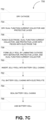
- FIG. 7C depicts a flowchart illustrating a process 750 for assembling a battery cell consistent with implementations of the current subject matter.
- the process 750 can be performed to assemble the battery cell 100.
- the process 750 can be performed to assemble, into the battery cell 100, the dual function current collector 110, the protective layer 120, the separator 130, the first electrode 140, and the current collector 150.
- the process 700, the process 720, and/or the process 750 may implement operation 602 of the process 600.
- a cathode can be dried (752).
- the first electrode 140 e.g., metal oxide formed on top of the current collector 150 by the process 720
- the first electrode 140 can be dried at 125°C for 10 hours.
- a dual function current collector and protective layer can be dried (754).
- the dual function current collector 110 e.g., copper foil and/or copper plated foil
- the protective layer 120 e.g., polymer and/or polymer composite
- the cathode, the dual function collector, and the protective layer can be punched into pieces with an electrode tab (756).
- a jelly roll can be formed by laminating the cathode with a separator, the protective layer, and the dual function current collector (758).
- the first electrode 140 can be laminated first with the separator 130 (e.g., porous polyethylene) followed by the protective layer 120 and the dual function current collector 110.
- the jelly roll can be inserted into a battery cell casing (760).
- the resulting jelly roll can be inserted into a composite bag formed from, for example, aluminum (Al).
- jelly roll may refer to a structure formed by at least layering, for example, the cathode, the separator, the protective layer, and the dual function current collector.
- the battery cell casing is filled with an electrolyte (762).
- the battery cell 100 can be filled with the liquid electrolyte 200, which can saturate at least the protective layer 120, the separator 130, and/or the first electrode 140.
- the liquid electrolyte 200 may contain metal ions such as, for example, lithium ions.
- filling the battery cell 100 with the liquid electrolyte 200 renders the protective layer 120 and the separator 130 ionically conductive.
- the battery cell casing can be sealed (764) and the battery cell can be aged (766).
- the battery cell 100 can be sealed and aged for 16 hours.
- the aged battery cell 100 is subsequently subject to an activation process (e.g., operation 604 of the process 600), during which the battery cell 100 can be charged at a low rate (e.g., ⁇ 1 10 C rate or charging to its fully charged state in ten hours) and a high voltage (e.g., > 4.2 volts).
- the aged battery cell 100 is activated in this manner to at least form, in situ, the second electrode 300 (e.g., anode) from lithium metal extracted from the first electrode 140.
- sample cells sample lithium composite films, and sample protective layers are provided for illustrative purposes only. It should be appreciated that different cells, lithium composite films, and protective layers may be formed in accordance with the present disclosure.
- the dual function current collector 110 is formed without the protective layer 120.
- copper (Cu) foil having a thickness of 9 microns is used to form the dual function current collector 110 without the protective layer 120.
- the first electrode 140 (e.g., cathode) is formed on top of the current collector 150 by at least performing the process 720.
- the first electrode 140 is formed from a lithium nickel manganese cobalt oxide (LiNi 0.5 Mn 0.3 Co 0.2 O 2 ).
- LiNi 0.5 Mn 0.3 Co 0.2 O 2 lithium nickel manganese cobalt oxide
- PVDF polyvinylidene fluoride
- NMP N-methylpyrrolidone
- a flowable second slurry can then be formed by adding 560.4 grams of lithium nickel manganese cobalt oxide (LiNi 0.5 Mn 0.3 Co 0.2 O 2 ) to this first slurry and mixing for 30 minutes at 6500 revolutions per minute.
- additional amounts of N-methylpyrrolidone may be added to adjust the viscosity of the second slurry.
- the resulting second slurry (e.g., electrode slurry) is coated onto the current collector 150, which may be aluminum (Al) foil having a thickness of 15 microns.
- the coating may be performed using an automatic coating machine with the first heat zone set to approximately 80°C and the second heat zone set to approximately 130°C to remove the liquid solvent (e.g., N-methylpyrrolidone) present in the second slurry.
- the first electrode 140 and the current collector 150 can have a combined thickness of approximately 300 microns.
- the first electrode 140 is coated with an additional layer containing polyvinylidene fluoride LBG-1 from Arkema Inc..
- a third slurry is formed by mixing 50 grams of polyvinylidene fluoride and 50 grams of a silicon dioxide (SiO 2 ) nano powder into 500 grams of N-methylpyrrolidone, and mixing for 30 minutes at 6500 revolutions per minute.
- the first electrode 140 is coated with a 5 micron thick layer of this third slurry. Once dried, the first electrode 140 is compressed to a thickness of approximately 225 microns.
- the dual function current collector 110 and the first electrode 140 is punched into pieces using an electrode tab that measures approximately 0.6 centimeters wide and 1 centimeter long.
- the dual function current collector 110 e.g., copper foil
- the first electrode 140 is punched into pieces measuring 4.7 centimeters in length and 6.0 centimeters in width.
- Both the dual function current collector 110 and the first electrode 140 is dried at 125°C for 16 hours.
- a jelly roll is formed by laminating the dual function current collector 110, the first electrode 140, and the current collector 150 on opposite sides of the separator 130, which may be approximately 40 microns thick. As such, the resulting jelly roll may have the dual function current collector 110 on one side of the separator 130 while the first electrode 140 and the current collector 150 may be on the opposite side of the separator 130.
- the jelly roll is inserted into an aluminum composite bag, which has been dried in a vacuum oven set to 70°C for 16 hrs.
- the aluminum composite bag can then be filled with an organic carbonate based liquid electrolyte containing lithium hexafluorophosphate (LiPF 6 ) before the aluminum composite bag is sealed, at 190°C, to form the battery cell 100.
- the sealed aluminum composite bag is allowed to rest for 16 hours before being charged, at room temperature, to 4.6V at a rate of 1 70 C rate or 70 hours to its fully charged state.
- the battery cell 100 is allowed to rest for 7 additional days at which point the battery cell 100 is punctured, under vacuum, to release any gases before being resealed.
- the resulting battery cell 100 can serve as a control sample.
- FIG. 8A depicts a line graph 800 illustrating a charge profile and a discharge profile of the battery cell 100 consistent with implementations of the current subject matter.
- the line graph 800 illustrates the capacity of the battery cell 100 relative to the charge voltage and the discharge voltage of the battery cell 100, as measured at room temperature.
- the ratio of discharge capacity relative to charge capacity is approximately 38.75%.
- the protective layer 120 is formed on the surface of the dual function current collector 110 by at least performing the process 700.
- the protective layer 120 is formed from polyethylene oxide (PEO) while the dual function current collector 110 is formed from copper (Cu) foil.
- a binder solution is formed by dissolving the 46.5 grams of polyethylene oxide binder into 465 grams of water.
- carbon black e.g., Super-P
- RPM revolutions per minute
- SBR styrene butadiene rubber
- This resulting slurry is coated onto the surface of copper (Cu) foil having a thickness of 9 microns.
- the coating is performed using an automatic coating machine with the first heat zone set to approximately 130°C and the second heat zone set to approximately 180°C to remove the water present in the slurry.
- the protective layer 120 can have an average thickness of approximately 2-15 microns.
- the first electrode 140 (e.g., cathode) is formed on top of the current collector 150 by at least performing the process 720.
- the first electrode 140 is formed from a lithium nickel manganese cobalt oxide (LiNi 0.5 Mn 0.3 Co 0.2 O 2 ).
- PVDF polyvinylidene fluoride
- NMP N-methylpyrrolidone
- graphite is added to this binder solution and mixed for 15 minutes at 6500 revolutions per minute to form a first slurry.
- a flowable second slurry can then be formed by adding 560.4 grams of lithium nickel manganese cobalt oxide (LiNi 0.5 Mn 0.3 Co 0.2 O 2 ) to this first slurry and mixing for 30 minutes at 6500 revolutions per minute.
- additional amounts of N-methylpyrrolidone may be added to adjust the viscosity of the second slurry.
- the resulting second slurry e.g., electrode slurry
- the resulting second slurry (e.g., electrode slurry) is coated onto the current collector 150, which may be aluminum (Al) foil having a thickness of 15 microns.
- the coating may be performed using an automatic coating machine with the first heat zone set to approximately 80°C and the second heat zone set to approximately 130°C to remove the N-methylpyrrolidone present in the second slurry.
- the first electrode 140 and the current collector 150 can have a combined thickness of approximately 300 microns, which is further compressed to a thickness of approximately 225 microns.
- the battery cell 100 is formed by performing the process 750.
- forming the battery cell 100 can include drying the dual function current collector 110, the protective layer 120, and the first electrode 140 at 125°C for 16 hours.
- the dual function current collector 110, the protective layer 120, and the first electrode 140 is further punched into pieces using an electrode tab.
- a jelly roll is formed from the dual function current collector 110, the protective layer 120, the separator 130, the first electrode 140, and the current collector 150.
- the dual function current collector 110, the protective layer 120, the separator 130, the first electrode 140, and the current collector 150 is laminated such that the dual function current collector 110 and the protective layer 120 are on one side of the separator 130 while the first electrode 140 and the current collector 150 are on the opposite side of the separator 130.
- the separator 130 can have a thickness of approximately 20 microns.
- This jelly roll is inserted flat into an aluminum (Al) composite bag that has been dried for 16 hours in a vacuum oven set to 70°C.
- the aluminum composite bag is filled with an organic carbonate based liquid electrolyte containing lithium hexafluorophosphate (LiPF 6 ) before the aluminum composite bag is sealed to form the battery cell 100.
- the battery cell 100 may be allowed to rest for approximately 16 hours before being subject to an activation process that includes charging, at room temperature, the battery cell 100 to 4.6 volts at a rate of 1 70 C rate.
- the activated battery cell 100 is allowed to rest for 7 additional days at which point the battery cell 100 is punctured, under vacuum, to release any gases before being resealed.
- the protective layer 120 is formed on the surface of the dual function current collector 110 by at least performing the process 700.
- the protective layer 120 is formed from polyethylene oxide (PEO) while the dual function current collector 110 is formed from copper (Cu) foil.
- a binder solution is formed by dissolving the 100 grams of polyethylene oxide binder into 1000 grams of deionized water and mixing for 120 minutes at 5000 revolutions per minute (RPM) to from a slurry.
- This slurry is coated onto the surface of copper (Cu) foil having a thickness of 9 microns.
- the coating is performed using an automatic coating machine with the first heat zone set to approximately 130°C and the second heat zone set to approximately 180°C to remove the water present in the slurry.
- the protective layer 120 can have an average thickness of approximately 2-15 microns.
- the first electrode 140 (e.g., cathode) is formed on top of the current collector 150 by at least performing the process 720.
- the first electrode 140 is formed from a lithium nickel manganese cobalt oxide (LiNi 0.5 Mn 0.3 Co 0.2 O 2 ).
- PVDF polyvinylidene fluoride
- NMP N-methylpyrrolidone
- graphite is added to this binder solution and mixed for 15 minutes at 6500 revolutions per minute to form a first slurry.
- a flowable second slurry can then be formed by adding 560.4 grams of lithium nickel manganese cobalt oxide (LiNi 0.5 Mn 0.3 Co 0.2 O 2 ) to this first slurry and mixing for 30 minutes at 6500 revolutions per minute.
- additional amounts of N-methylpyrrolidone may be added to adjust the viscosity of the second slurry.
- the resulting second slurry e.g., electrode slurry
- the resulting second slurry (e.g., electrode slurry) is coated onto the current collector 150, which may be aluminum (Al) foil having a thickness of 15 microns.
- the coating may be performed using an automatic coating machine with the first heat zone set to approximately 80°C and the second heat zone set to approximately 130°C to remove the N-methylpyrrolidone present in the second slurry.
- the first electrode 140 and the current collector 150 can have a combined thickness of approximately 300 microns, which is further compressed to a thickness of approximately 225 microns.
- the dual function current collector 110, the protective layer 120, the separator 130, the first electrode 140, and the current collector 150 is laminated such that the dual function current collector 110 and the protective layer 120 are on one side of the separator 130 while the first electrode 140 and the current collector 150 are on the opposite side of the separator 130.
- the separator 130 can have a thickness of approximately 40 microns.
- This jelly roll is inserted flat into an aluminum (Al) composite bag that has been dried for 16 hours in a vacuum oven set to 70°C.
- the aluminum composite bag is filled with an organic carbonate based liquid electrolyte containing lithium hexafluorophosphate (LiPF 6 ) before the aluminum composite bag is sealed to form the battery cell 100.
- the battery cell 100 may be allowed to rest for approximately 16 hours before being subject to an activation process that includes charging, at room temperature, the battery cell 100 to 4.6 volts at a rate of 1 70 C rate.
- the activated battery cell 100 is allowed to rest for 7 additional days at which point the battery cell 100 is punctured, under vacuum, to release any gases before being resealed.
- FIG. 8B depicts a line graph 810 illustrating a charge profile and a discharge profile of the battery cell 100 consistent with implementations of the current subject matter.
- the line graph 810 illustrates the capacity of the battery cell 100 relative to the charge voltage and the discharge voltage of the battery cell 100, as measured at room temperature.
- the ratio of discharge capacity relative to charge capacity is approximately 71.2%.
- the protective layer 120 is formed on the surface of the dual function current collector 110 by at least performing the process 700.
- the protective layer 120 is formed from polyethylene oxide (PEO) while the dual function current collector 110 is formed from copper (Cu) foil.
- PEO polyethylene oxide
- Cu copper
- a binder solution is formed by dissolving the 100 grams of polyethylene oxide binder into 1000 grams of deionized water and mixing for 120 minutes at 5000 revolutions per minute (RPM) to from a slurry. This slurry is coated onto the surface of copper (Cu) foil having a thickness of 9 microns.
- the coating is performed using an automatic coating machine with the first heat zone set to approximately 130°C and the second heat zone set to approximately 180°C to remove the deionized water present in the slurry.
- the protective layer 120 can have an average thickness of approximately 2-15 microns.
- the first electrode 140 (e.g., cathode) is formed on top of the current collector 150 by at least performing the process 720.
- the first electrode 140 is formed from a lithium nickel manganese cobalt oxide (LiNi 0.5 Mn 0.3 Co 0.2 O 2 ).
- LiNi 0.5 Mn 0.3 Co 0.2 O 2 lithium nickel manganese cobalt oxide
- NMP N-methylpyrrolidone
- a flowable second slurry can then be formed by adding 92.2 grams of lithium nickel manganese cobalt oxide (LiNi 0.5 Mn 0.3 Co 0.2 O 2 ) to this first slurry and mixing for 30 minutes at 6500 revolutions per minute.
- additional amounts of N-methylpyrrolidone may be added to adjust the viscosity of the second slurry.
- the resulting second slurry e.g., electrode slurry
- the current collector 150 which may be aluminum (Al) foil having a thickness of 15 microns.
- the coating may be performed using an automatic coating machine with the first heat zone set to approximately 80°C and the second heat zone set to approximately 130°C to remove the N-methylpyrrolidone present in the second slurry.
- the first electrode 140 and the current collector 150 can have a combined thickness of approximately 300 microns, which is further compressed to a thickness of approximately 225 microns.
- the battery cell 100 is formed by performing the process 750.
- forming the battery cell 100 can include drying the dual function current collector 110, the protective layer 120, and the first electrode 140 at 125°C for 16 hours.
- the dual function current collector 110, the protective layer 120, and the first electrode 140 is further punched into pieces using an electrode tab.
- a jelly roll is formed from the dual function current collector 110, the protective layer 120, the separator 130, the first electrode 140, and the current collector 150.
- the dual function current collector 110, the protective layer 120, the separator 130, the first electrode 140, and the current collector 150 is laminated such that the dual function current collector 110 and the protective layer 120 are on one side of the separator 130 while the first electrode 140 and the current collector 150 are on the opposite side of the separator 130.
- the separator 130 can have a thickness of approximately 25 microns.
- This jelly roll is inserted flat into an aluminum (Al) composite bag that has been dried for 16 hours in a vacuum oven set to 70°C.
- the aluminum composite bag is filled with an organic carbonate based liquid electrolyte containing lithium hexafluorophosphate (LiPF 6 ) before the aluminum composite bag is sealed to form the battery cell 100.
- the battery cell 100 may be allowed to rest for approximately 16 hours before being subject to an activation process that includes charging, at room temperature, the battery cell 100 to 4.6 volts at a rate of 1 70 C rate.
- the activated battery cell 100 is allowed to rest for 7 additional days at which point the battery cell 100 is punctured, under vacuum, to release any gases before being resealed.
- FIG. 8C depicts a line graph 820 illustrating a charge profile and a discharge profile of the battery cell 100 consistent with implementations of the current subject matter.
- the line graph 820 illustrates the capacity of the battery cell 100 relative to the charge voltage and the discharge voltage of the battery cell 100, as measured at room temperature.
- the ratio of discharge capacity relative to charge capacity is approximately 74.2%. It should be appreciated that the discharge of the battery cell 100 is suspended at approximately 1.4 ampere-hour, thereby causing the voltage dip observed at around 1.4 ampere-hour.
- the protective layer 120 is formed on the surface of the dual function current collector 110 by at least performing the process 700.
- the protective layer 120 is formed from polyvinylidene fluoride (PVDF LBG-1) (e.g., manufactured by Arkema Inc. of King of Prussia, PA) while the dual function current collector 110 is formed from copper (Cu) foil.
- PVDF LBG-1 polyvinylidene fluoride
- Cu copper
- a binder solution is formed by dissolving the 10 grams of the polyvinylidene fluoride binder into 125 grams of N-methylpyrrolidone (NMP) and mixing for 120 minutes at 5000 revolutions per minute (RPM) to from a slurry.
- NMP N-methylpyrrolidone
- This slurry is coated onto the surface of copper (Cu) foil having a thickness of 9 microns.
- the coating is performed using an automatic coating machine with the first heat zone set to approximately 130°C and the second heat zone set to approximately 180°C to remove the N-methylpyrrolidone present in the slurry.
- the protective layer 120 can have an average thickness of approximately 2-15 microns.
- the first electrode 140 (e.g., cathode) is formed on top of the current collector 150 by at least performing the process 720.
- the first electrode 140 is formed from a lithium nickel manganese cobalt oxide (LiNi 0.5 Mn 0.3 Co 0.2 O 2 ).
- LiNi 0.5 Mn 0.3 Co 0.2 O 2 lithium nickel manganese cobalt oxide
- PVDF high molecular weight polyvinylidene fluoride
- a flowable second slurry can then be formed by adding 92.2 grams of lithium nickel manganese cobalt oxide (LiNi 0.5 Mn 0.3 Co 0.2 O 2 ) to this first slurry and mixing for 30 minutes at 6500 revolutions per minute.
- additional amounts of N-methylpyrrolidone may be added to adjust the viscosity of the second slurry.
- the resulting second slurry e.g., electrode slurry
- the current collector 150 which may be aluminum (Al) foil having a thickness of 15 microns.
- the coating may be performed using an automatic coating machine with the first heat zone set to approximately 80°C and the second heat zone set to approximately 130°C to remove the N-methylpyrrolidone present in the second slurry.
- the first electrode 140 and the current collector 150 can have a combined thickness of approximately 300 microns, which is further compressed to a thickness of approximately 225 microns.
- the battery cell 100 is formed by performing the process 750.
- forming the battery cell 100 can include drying the dual function current collector 110, the protective layer 120, and the first electrode 140 at 125°C for 16 hours.
- the dual function current collector 110, the protective layer 120, and the first electrode 140 is further punched into pieces using an electrode tab.
- a jelly roll is formed from the dual function current collector 110, the protective layer 120, the separator 130, the first electrode 140, and the current collector 150.
- the dual function current collector 110, the protective layer 120, the separator 130, the first electrode 140, and the current collector 150 is laminated such that the dual function current collector 110 and the protective layer 120 are on one side of the separator 130 while the first electrode 140 and the current collector 150 are on the opposite side of the separator 130.
- the separator 130 can have a thickness of approximately 25 microns.
- This jelly roll is inserted flat into an aluminum (Al) composite bag that has been dried for 16 hours in a vacuum oven set to 70°C.
- the aluminum composite bag is filled with an organic carbonate based liquid electrolyte containing lithium hexafluorophosphate (LiPF 6 ) before the aluminum composite bag is sealed to form the battery cell 100.
- the battery cell 100 may be allowed to rest for approximately 16 hours before being subject to an activation process that includes charging, at room temperature, the battery cell 100 to 4.6 volts at a rate of 1 70 C rate.
- the activated battery cell 100 is allowed to rest for 7 additional days at which point the battery cell 100 is punctured, under vacuum, to release any gases before being resealed.
- FIG. 8D depicts a line graph 830 illustrating a charge profile and a discharge profile of the battery cell 100 consistent with implementations of the current subject matter.
- the line graph 830 illustrates the capacity of the battery cell 100 relative to the charge voltage and the discharge voltage of the battery cell 100, as measured at room temperature.
- the ratio of discharge capacity relative to charge capacity is approximately 80%. It should be appreciated that the discharge of the battery cell 100 is suspended at approximately 1.3 ampere-hour, thereby causing the voltage dip observed at around 1.3 ampere-hour.
- the protective layer 120 is formed on the surface of the dual function current collector 110 by at least performing the process 700.
- the protective layer 120 is formed from polyvinylidene fluoride (PVDF LBG-1) (e.g., manufactured by Arkema Inc. of King of Prussia, PA) while the dual function current collector 110 is formed from copper (Cu) foil.
- PVDF LBG-1 polyvinylidene fluoride
- Cu copper
- a binder solution is formed by dissolving the 10 grams of the polyvinylidene fluoride binder into 125 grams of N-methylpyrrolidone (NMP) and mixing for 120 minutes at 5000 revolutions per minute (RPM) to from a slurry.
- NMP N-methylpyrrolidone
- This slurry is coated onto the surface of copper (Cu) foil having a thickness of 9 microns.
- the coating is performed using an automatic coating machine with the first heat zone set to approximately 130°C and the second heat zone set to approximately 180°C to remove the N-methylpyrrolidone present in the slurry.
- the protective layer 120 can have an average thickness of approximately 2-15 microns.
- the first electrode 140 (e.g., cathode) is formed on top of the current collector 150 by at least performing the process 720.
- the first electrode 140 is formed from a lithium nickel manganese cobalt oxide (LiNi 0.4 Mn 0.3 Co 0.2 O 2 ).
- PVDF high molecular weight polyvinylidene fluoride
- BM700 e.g., manufactured by Zeon Corporation of Tokyo Japan
- NMP N-methylpyrrolidone
- carbon black is dissolved into 26.25 grams of N-methylpyrrolidone and mixed for 15 minutes at 6500 revolutions per minute to form a binder solution.
- graphite is added to this binder solution and mixed for 15 minutes at 6500 revolutions per minute to form a first slurry.
- the battery cell 100 is formed by performing the process 750.
- forming the battery cell 100 can include drying the dual function current collector 110, the protective layer 120, and the first electrode 140 at 125°C for 16 hours.
- the dual function current collector 110, the protective layer 120, and the first electrode 140 is further punched into pieces using an electrode tab.
- a jelly roll is formed from the dual function current collector 110, the protective layer 120, the separator 130, the first electrode 140, and the current collector 150.
- the dual function current collector 110, the protective layer 120, the separator 130, the first electrode 140, and the current collector 150 is laminated such that the dual function current collector 110 and the protective layer 120 are on one side of the separator 130 while the first electrode 140 and the current collector 150 are on the opposite side of the separator 130.
- the separator 130 can have a thickness of approximately 40 microns.
- This jelly roll is inserted flat into an aluminum (Al) composite bag that has been dried for 16 hours in a vacuum oven set to 70°C.
- the aluminum composite bag is filled with an organic carbonate based liquid electrolyte containing lithium hexafluorophosphate (LiPF 6 ) before the aluminum composite bag is sealed to form the battery cell 100.
- the battery cell 100 may be allowed to rest for approximately 16 hours before being subject to an activation process that includes charging, at room temperature, the battery cell 100 to 4.6 volts at a rate of 1 70 C rate.
- the activated battery cell 100 is allowed to rest for 7 additional days at which point the battery cell 100 is punctured, under vacuum, to release any gases before being resealed.
- FIG. 8E depicts a line graph 840 illustrating a charge profile and a discharge profile of the battery cell 100 consistent with implementations of the current subject matter.
- the line graph 840 illustrates the capacity of the battery cell 100 relative to the charge voltage and the discharge voltage of the battery cell 100, as measured at room temperature.
- the ratio of discharge capacity relative to charge capacity is approximately 90%.
- FIG. 8F depicts a scatter plot 850 illustrating a cycle life performance of the battery cell 100 consistent with implementations of the current subject matter.
- the scatter plot 850 illustrates the cycle life of the battery cell 100 (e.g., measured in the number of complete charge and discharge cycles supported by the battery cell 100 prior to depletion) relative to the capacity of the battery cell 100, when the battery cell is configured as the sample cell 5.
- the coating is performed using an automatic coating machine with the first heat zone set to approximately 130°C and the second heat zone set to approximately 180°C to remove the deionized water present in the slurry.
- the protective layer 120 can have an average thickness of approximately 2-15 microns.
- PVDF high molecular weight polyvinylidene fluoride
- BM700 e.g., manufactured by Zeon Corporation of Tokyo, Japan
- NMP N-methylpyrrolidone
- carbon black is dissolved into 26.25 grams of N-methylpyrrolidone and mixed for 15 minutes at 6500 revolutions per minute to form a binder solution.
- graphite is added to this binder solution and mixed for 15 minutes at 6500 revolutions per minute to form a first slurry.
- a flowable second slurry can then be formed by adding 93.1 grams of lithium nickel manganese cobalt oxide (LiNi 0.4 Mn 0.3 Co 0.3 O 2 ) (NMC433) to this first slurry and mixing for 30 minutes at 6500 revolutions per minute.
- additional amounts of N-methylpyrrolidone may be added to adjust the viscosity of the second slurry.
- the resulting second slurry e.g., electrode slurry
- the current collector 150 which may be aluminum (Al) foil having a thickness of 15 microns.
- the coating may be performed using an automatic coating machine with the first heat zone set to approximately 80°C and the second heat zone set to approximately 130°C to remove the N-methylpyrrolidone present in the second slurry.
- the first electrode 140 and the current collector 150 can have a combined thickness of approximately 300 microns, which is further compressed to a thickness of approximately 225 microns.
- the battery cell 100 is formed by performing the process 750.
- forming the battery cell 100 can include drying the dual function current collector 110, the protective layer 120, and the first electrode 140 at 125°C for 16 hours.
- the dual function current collector 110, the protective layer 120, and the first electrode 140 is further punched into pieces using an electrode tab.
- a jelly roll is formed from the dual function current collector 110, the protective layer 120, the separator 130, the first electrode 140, and the current collector 150.
- the dual function current collector 110, the protective layer 120, the separator 130, the first electrode 140, and the current collector 150 is laminated such that the dual function current collector 110 and the protective layer 120 are on one side of the separator 130 while the first electrode 140 and the current collector 150 are on the opposite side of the separator 130.
- This jelly roll is inserted flat into an aluminum (Al) composite bag that has been dried for 16 hours in a vacuum oven set to 70°C.
- the aluminum composite bag is filled with an organic carbonate based liquid electrolyte containing lithium hexafluorophosphate (LiPF 6 ) before the aluminum composite bag is sealed to form the battery cell 100.
- the battery cell 100 may be allowed to rest for approximately 16 hours before being subject to an activation process that includes charging, at room temperature, the battery cell 100 to 4.6 volts at a rate of 1 70 C rate.
- the activated battery cell 100 is allowed to rest for 7 additional days at which point the battery cell 100 is punctured, under vacuum, to release any gases before being resealed.
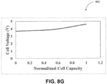
- FIG. 8G depicts a line graph 860 illustrating a charge profile of the battery cell 100 consistent with implementations of the current subject matter.
- the line graph 860 illustrates the capacity of the battery cell 100 relative to the charge voltage voltage of the battery cell 100, as measured at room temperature.
- the protective layer 120 is formed from polyamideimides, polyimides, polytetrafluoroethylene (PTFE), carboxymethyl cellulose (CMC), polyvinylidene fluoride (PVDF), polyvinyl alcohol (PVA), styrene butadiene rubber (SBR), and/or mixtures thereof.
- the protective layer 120 is formed from a polyimide.
- the protective layer 120 is formed from a carboxymethyl cellulose.
- the protective layer 120 is formed from a crosslinkable polymer.
- Suitable crosslinkable polymers can include, for example, polybenzophenones, polyacrylates, polyvinyls, polystyrenes, polysulfones, 2,3-dihydrofurancontaining polymers, carboxymethyl celluloses (CMC), polyamideimides, polyimides, styrene-containing copolymers, and mixtures thereof.
- the crosslinkable polymer is a polyamideimide.
- the crosslinkable polymer is a polyimide.
- the crosslinkable polymer is a carboxymethyl cellulose.
- the protective layer 120 is formed from a crosslinked polymer.
- Suitable crosslinked polymers can include, for example, polybenzophenones, polyacrylates, polyvinyls, polystyrenes, polysulfones, 2,3-dihydrofuran-containing polymers, carboxymethyl celluloses (CMC), polyamideimides, polyimides, styrene-containing copolymers, and/or mixtures thereof.
- the crosslinked polymer is a polyamideimide.
- the crosslinked polymer is a polyimide.
- the crosslinked polymer is a carboxymethyl cellulose.
- the protective layer 120 is formed from a thermally crosslinkable polymer.
- Suitable thermally crosslinkable polymers can include, for example, polybenzophenones, polyacrylates, polyvinyls, polystyrenes, polysulfones, 2,3-dihydrofuran-containing polymers, carboxymethyl celluloses (CMC), polyamideimides, polyimides, styrene-containing copolymers, and/or mixtures thereof.
- the thermally crosslinkable polymer is a polyamideimide.
- the thermally crosslinkable polymer is a polyimide.
- the thermally crosslinkable polymer is a carboxymethyl cellulose.
- the protective layer 120 is formed from a photo crosslinkable polymer.
- Suitable photo crosslinkable polymers can include, for example, polybenzophenones, polyacrylates, polyvinyls, polystyrenes, polysulfones, 2,3-dihydrofurancontaining polymers, styrene-containing copolymers, and/or mixtures thereof.
- the protective layer 120 is formed from its precursors via polymerization on the surface of the core of the coated electroactive particle (e.g., the dual function current collector 110) provided herein.
- the precursors of a polymer is monomers of the polymer.
- the precursors of a polymer is crosslinkable polymers.
- the polyamideimide forming the protective layer 120 is formed from a polyamideimide via crosslinking on the surface of the core of the coated electroactive particle (e.g., the dual function current collector 110) provided herein.
- the polyimide forming the protective layer 120 is formed from a polyimide via crosslinking on the surface of the core of the coated electroactive particle provided herein (e.g., the dual function current collector 110).
- the protective layer 120 is formed from a polyamideimide, polyimide, and/or a mixture thereof.
- the polyamideimide is aromatic, aliphatic, cycloaliphatic, and/or a mixture thereof.
- the polyamideimide is an aromatic polyamideimide.
- the polyamideimide is an aliphatic polyamideimide.
- the polyamideimide is a cycloaliphatic polyamideimide.
- the polyimide is aromatic, aliphatic, cycloaliphatic, and/or a mixture thereof.
- the polyimide is an aromatic polyimide. In some implementations of the current subject matter, the polyimide is an aliphatic polyimide. In some implementations of the current subject matter, the polyimide is a cycloaliphatic polyimide.
- the protective layer 120 is formed from TORLON ® AI-30, TORLON ® AI-50, TORLON ® 4000, or TORLON ® 4203L (e.g., manufactured by Solvay Advanced Polymers, L.L.C. of Augusta, GA). Alternately and/or additionally, the protective layer 120 is formed from U-VARNISH ® (e.g., manufactured by UBE American Inc. of New York, NY). In some implementations of the current subject matter, the protective layer 120 is formed from TORLON ® AI-30. In some implementations of the current subject matter, the protective layer 120 is formed from TORLON ® AI-50.
- the protective layer 120 is formed from TORLON ® 4000. In some implementations of the current subject matter, the protective layer 120 is formed from TORLON ® 4203L. In some implementations of the current subject matter, the protective layer 120 is formed from U-VARNISH ® .
- polyamideimide and polyimides can include those described in Loncrini and Witzel, Journal of Polymer Science Part A-1: Polymer Chemistry 1969, 7, 2185-2193 ; Jeon and Tak, Journal of Applied Polymer Science 1996, 60, 1921-1926 ; Seino et al., Journal of Polymer Science Part A: Polymer Chemistry 1999, 37, 3584-3590 ; Seino et al., High Performance Polymers 1999, 11, 255-262 ; Matsumoto, High Performance Polymers 2001, 13, S85-S92 ; Schab-Balcerzak et al., European Polymer Journal 2002, 38, 423-430 ; Eichstadt et al., Journal of Polymer Science Part B: Polymer Physics 2002, 40, 1503-1512 ; and Fang et al., Polymer 2004, 45, 2539-2549 .
- the protective layer 120 is formed from a polyamideimide and a polyamine via polymerization on the surface of the core of the coated electroactive particle provided herein (e.g., the dual function current collector 110).
- the protective layer 120 is formed from an aromatic, aliphatic, and/or cycloaliphatic polyimide via a condensation reaction of an aromatic, aliphatic, or cycloaliphatic polyanhydride.
- a dianhydride is combined with an aromatic, aliphatic, and/or cycloaliphatic polyamine to form a polyamic acid.
- the dianhydride is combined with a diamine and/or a triamine to form the polyamic acid.
- the polyamic acid can subsequently be subject to chemical and/or thermal cyclization to form the polyimide.
- the protective layer 120 is formed from a polyanhydride and a polyamine via polymerization on the surface of the core of the coated electroactive particle provided herein (e.g., the dual function current collector 110).
- suitable polyanhydrides, polyamines, polyamideimide, and/or polyimides can include, for example, those described in Eur. Pat. App. Pub. Nos. EP 0450549 and EP 1246280 ; U.S. Pat. No. 5,504,128 ; and U.S. Pat. App. Pub. Nos. 2006/0099506 and 2007/0269718 .
- suitable polyanhydrides can include, for example, butanetetracarboxylic dianhydride, meso -1,2,3,4-butanetetracarboxylic dianhydride, dl -1,2,3,4-butanetetracarboxylic dianhydride, cyclobutane tetracarboxylic dianhydride, 1,2,3,4-cyclopentane tetracarboxylic dianhydride, cyclohexane tetracarboxylic dianhydride, 1,2,3,4-cyclohexanetetracarboxylic dianhydride, cis- 1,2,3,4-cyclohexanetetracarboxylic dianhydride, trans -1,2,3,4-cyclohexanetetracarboxylic dianhydride, bicyclo[2.2.2]octane-2,3,5,6-tetracarboxylic 2,3:5,6-dianhydride, bicyclo[2.2.2]octan
- suitable polyamines can include, for example, 4,4'-methylenebis(2,6-dimethylaniline), 4,4'-oxydianiline, m- phenylenediamine, p -phenylenediamine, benzidene, 3,5-diaminobenzoic acid, o -dianisidine, 4,4'-diaminodiphenyl methane, 4,4'-methylenebis(2,6-dimethylaniline), 1,4-diaminobutane, 1,6-diaminohexane, 1,7-diaminoheptane, 1,9-diaminononane, 1,10-diaminodecane, 1,12-diaminododecane, 5-amino-1,3,3-trimethylcyclohexanemethylamine, 2,5-bis(aminomethyl)bicyclo[2.2.1]heptane, 2,6-bis(aminomethyl)
- the polyimide is poly(4,4'-phenyleneoxyphenylene pyromellitic imide) and/or poly(4,4'-phenyleneoxyphenylene- co -1,3-phenylenebenzophenonetetracarboxylic diimide).
- phrases such as "at least one of” or “one or more of” may occur followed by a conjunctive list of elements or features.
- the term “and/or” may also occur in a list of two or more elements or features. Unless otherwise implicitly or explicitly contradicted by the context in which it used, such a phrase is intended to mean any of the listed elements or features individually or any of the recited elements or features in combination with any of the other recited elements or features.
- the phrases “at least one of A and B;” “one or more of A and B;” and “A and/or B” are each intended to mean "A alone, B alone, or A and B together.”
- a similar interpretation is also intended for lists including three or more items.
- phrases “at least one of A, B, and C;” “one or more of A, B, and C;” and “A, B, and/or C” are each intended to mean “A alone, B alone, C alone, A and B together, A and C together, B and C together, or A and B and C together.”
- Use of the term “based on,” above and in the claims is intended to mean, “based at least in part on,” such that an unrecited feature or element is also permissible.
Landscapes
- Chemical & Material Sciences (AREA)
- Chemical Kinetics & Catalysis (AREA)
- Electrochemistry (AREA)
- General Chemical & Material Sciences (AREA)
- Engineering & Computer Science (AREA)
- Manufacturing & Machinery (AREA)
- Materials Engineering (AREA)
- Inorganic Chemistry (AREA)
- Cell Electrode Carriers And Collectors (AREA)
- Secondary Cells (AREA)
- Battery Electrode And Active Subsutance (AREA)
Description
- This application claims priority to
U.S. Provisional Patent Application No. 62/297,294 file on February 19, 2016 - The subject matter described herein relates generally to battery technologies and more specifically to current collectors.
- Lithium (e.g., lithium-ion) batteries typically include an electrode formed from lithium metal. For instance, lithium metal may be used to form the anode (e.g., negative electrode) of a lithium battery cell. Lithium metal may be an ideal material for the anode of a lithium battery cell due to the high specific capacity of lithium metal. Notably, at approximately 4400 milliampere-hours per gram (mAh/g), the specific capacity of lithium metal is more than ten times higher than that of graphite, which has a specific capacity of only 372 mAh/g. Document
US2013017441 discloses a method of forming a battery cell, wherein the method comprises providing a current collector and a protective structure that comprises a polymer layer and a single-ion conductive layer, and then intercalating lithium between the collector and the protective layer. DocumentUS2015050537 discloses a process for forming electrochemical cells with a liquid electrolyte comprising the in situ formation of a lithium electrode that is deposited, upon charging of the cell, between the current collector and a polymer layer. - According to the subject-matter of the present invention, there is provided a method of manufacturing a battery cell as specified in
claim 1. The activation process can include charging the battery at less than
- According to the invention, the protective layer is formed from a polymer. The protective layer can be formed from a crosslinked polymer and/or a non-crosslinked polymer. The protective layer is formed from a polymer composite that includes a plurality of different polymers. The polymer composite can further include one or more additives, the one or more additives comprising ceramic particles, metal salt particles, and metal stabilizers.
- According to the invention, the battery further includes an electrolyte. The electrolyte is a liquid electrolyte, the liquid electrolyte including metal ions, and the liquid electrolyte further including one or more organic solvents. The metal ions can include lithium ions, and wherein the one or more organic solvents comprise ethylene carbonate ((CH2O)2CO) and/or lithium hexafluorophosphate (Li1PF6). The electrolyte can additionally comprise a solid-state electrolyte. The solid-state electrolyte can be a glass-ceramic binary sulfide electrolyte and/or a polymer electrolyte.
- In some variations, the battery can further include a second current collector, the second current collector being coupled with the first electrode. The battery can further include a safety layer, the safety layer being deposited on the second current collector, and the safety layer being configured to respond to a temperature trigger and/or a voltage trigger.
- According to the invention, the metal extracted from the first electrode and deposited between the first current collector and the protective layer can include dendrites. The protective layer is configured to prevent the dendrites from penetrating the separator and causing an internal short within the battery.
- According to the invention, the activation process can cause a reduction at the first electrode, the reduction extracting metal from the first electrode, and the metal extracted from the first electrode being deposited between the first current collector and the protective layer to form the second electrode in situ between the first current collector and the protective layer.
- The details of one or more variations of the subject matter described herein are set forth in the accompanying drawings and the description below. Other features and advantages of the subject matter described herein will be apparent from the description and drawings, and from the claims.
- The accompanying drawings, which are incorporated in and constitute a part of this specification, show certain aspects of the subject matter disclosed herein and, together with the description, help explain some of the principles associated with the disclosed implementations. In the drawings,
-
FIG. 1A depicts a schematic diagram illustrating a battery cell consistent with implementations of the current subject matter; -
FIG. 1B depicts a schematic diagram illustrating a battery cell consistent with implementations of the current subject matter; -
FIG. 2 depicts a schematic diagram illustrating a battery cell consistent with implementations of the current subject matter; -
FIG. 3 depicts a schematic diagram illustrating a battery cell consistent with implementations of the current subject matter; -
FIG. 4 depicts a schematic diagram illustrating a battery cell consistent with implementations of the current subject matter; -
FIG. 5 depicts a schematic diagram illustrating a battery cell consistent with implementations of the current subject matter; -
FIG. 6 depicts a flowchart illustrating a process for forming a lithium metal electrode in situ consistent with implementations of the current subject matter; -
FIG. 7A depicts a flowchart illustrating a process for forming a protective layer consistent with some implementations of the current subject matter; -
FIG. 7B depicts a flowchart illustrating a process for forming a cathode consistent with some implementations of the current subject matter; -
FIG. 7C depicts a flowchart illustrating a process for assembling a battery cell consistent with implementations of the current subject matter; -
FIG. 8A depicts a line graph illustrating a charge profile and a discharge profile of a battery cell consistent with implementations of the current subject matter; -
FIG. 8B depicts a line graph illustrating a charge profile and a discharge profile of a battery cell consistent with implementations of the current subject matter; -
FIG. 8C depicts a line graph illustrating a charge profile and a discharge profile of a battery cell consistent with implementations of the current subject matter; -
FIG. 8D depicts a line graph illustrating a charge profile and a discharge profile of a battery cell consistent with implementations of the current subject matter; -
FIG. 8E depicts a line graph illustrating a charge profile and a discharge profile of a battery cell consistent with implementations of the current subject matter; -
FIG. 8F depicts a scatter plot illustrating a cycle life performance of a battery cell consistent with implementations of the current subject matter; and -
FIG. 8G depicts a line graph illustrating a charge profile of a battery cell consistent with implementations of the current subject matter; - When practical, similar reference numbers denote similar structures, features, or elements.
- Lithium metal may be an ideal material for battery electrodes (e.g., anodes) due to the very high specific capacity (e.g., approximately 4440 mAh/g) of lithium metal. However, forming battery electrodes from lithium metal tends to be challenging in part because the low density of lithium metal renders the material especially fragile and difficult to handle during the production process. For instance, lithium has a density of approximately 0.534 grams per cubic centimeter (g/cm3) while copper has a density of approximately 8.7 g/cm3. As such, a large amount of lithium metal may be required in producing lithium batteries. In particular, the lithium foil used to form battery electrodes is typically much thicker (e.g., more than 100 microns (µm)) than copper foil, which may be as thin as 6 microns. But including a large volume of lithium metal in a battery cell may incur unnecessary cost and compromise battery performance. For example, the positive electrode (e.g., cathode) in a battery may be unable to match the capacity of a negative electrode (e.g., anode) formed from a large amount of lithium metal. Here, an excess of lithium metal may occupy space within the battery cell without providing any additional capacity, thereby limiting the overall energy density of the battery cell. This excess lithium metal may further promote the formation of lithium dendrites within the battery cell (e.g., during charging of the battery cell). The presence of lithium dendrites within a battery cell may reduce the Coulombic efficiency as well as the cycle life of the battery cell. Moreover, the presence of lithium dendrites may further give rise to significant safety risks including, for example, internal shorts that may escalate into thermal runaway and explosions.
- In some implementations of the current subject matter, a battery cell includes a current collector that is configured to enable an electrode (e.g., anode) to be formed from lithium metal in situ. For example, the current collector may be formed from copper (e.g., copper foil), plated copper (e.g., nickel plated copper foil, aluminum plated copper foil, and/or titanium plated copper foil), stainless steel (e.g., stainless steel foil), and/or titanium (e.g., titanium foil). According to some implementations of the current subject matter, the battery cell is subject to an activation process during which lithium metal is deposited on the surface of the current collector (e.g., the copper foil and/or the plated copper foil), thereby forming a lithium metal electrode (e.g., anode) in situ. For example, the cathode of the battery cell may be formed from a metal oxide (e.g., lithium cobalt oxide, lithium nickel cobalt oxide, lithium manganese nickel cobalt oxide), a doped salt (e.g., lithium iron phosphate), a metal fluoride (e.g., lithium fluoride (LiF)), a metal sulfide (e.g., lithium sulfide), and/or the like. The activation process includes charging the battery cell, thereby reducing the cathode of the battery cell. Metal that is extracted through the reduction of the cathode of the battery cell is deposited at the anode of the battery cell (e.g., on the surface of the current collector).
- In some implementations of the current subject matter, a battery cell is subject to an activation process during which an electrode (e.g., anode) in the battery cell may be formed from lithium metal in situ. The lithium metal forming the electrode may be lithium dendrites, which may be filaments of lithium metal capable of penetrating a separator (e.g., between the anode and the cathode) in the battery cell and causing an internal short. As such, according to some implementations of the current subject matter, a current collector (e.g., the copper foil) is further coated with a protective layer, which may also be formed in situ. This protective layer formed from a polymer and/or a polymer composite. Meanwhile, the lithium metal (e.g., lithium dendrites) that is extracted from the lithium metal oxide at the cathode of the battery cell is deposited between the current collector (e.g., the copper foil) and the protective layer. The protective layer prevents internal shorts by at least preventing the lithium dendrites forming the anode of the battery cell from penetrating the separator between the anode and the cathode of the battery cell.
- In some implementations of the current subject matter, a lithium metal electrode (e.g., anode) is formed in situ between a current collector (e.g., a copper foil and/or a plated copper foil) and a protective layer (e.g., a polymer and/or a polymer composite) of a battery cell. According to the invention, a lithium metal anode is formed by at least depositing, between the current collector and the protective layer, lithium metal extracted from a cathode of the battery cell during an activation process (e.g., charging of the battery cell). Forming the lithium metal electrode in situ obviates the highly inert environment required for manipulating highly reactive lithium metal (e.g., during lithium battery production). For instance, coating the surface of a lithium metal electrode with a protective layer (e.g., to prevent internal shorts) is typically performed in a dry room (e.g., with less than 2% relative humidity) in order to prevent the lithium metal from reacting with moisture present in the air. By contrast, forming a lithium metal electrode in situ eliminates these costly limitations associated with conventional lithium battery production techniques. In fact, various implementations of the current subject matter obviate the handling of highly reactive lithium metal during the production of lithium batteries. Moreover, a sufficiently thin layer of lithium metal may be deposited between the current collector and the protective layer such that the capacity of the lithium metal anode matches that of the corresponding cathode and no excess lithium metal is present in the battery cell. Producing lithium batteries in this manner can be less costly while the resulting lithium batteries can exhibit optimal overall energy density.
- For clarity and conciseness, various implementations of the current subject matter are described with respect to the production of lithium batteries having electrodes formed from lithium metal. However, it should be appreciated that various implementations of the current subject matter can also be applied to the production of other types of metal batteries including, for example, sodium (Na) batteries, potassium (K) batteries, and/or the like. Thus, the techniques disclosed herein may be used to form other metal electrodes in situ, thereby obviating the handling of reactive metals during the production of metal batteries.
-
FIG. 1A depicts a schematic diagram illustrating abattery cell 100 consistent with implementations of the current subject matter. Referring toFIG. 1B , thebattery cell 100 may include a dual functioncurrent collector 110, aprotective layer 120, aseparator 130, afirst electrode 140, and acurrent collector 150. - In some implementations of the current subject matter, the dual function
current collector 110 can be formed from copper (Cu) and/or plated copper. For example, thedual function collector 110 may be formed from copper foil, stainless steel foil, titanium foil, nickel (Ni) plated copper foil, aluminum (Al) plated copper foil, titanium (Ti) plated copper foil, and/or the like. The foil may have a thickness of approximately 10 microns. Meanwhile, thecurrent collector 150 may be formed from aluminum (Al) (e.g., aluminum foil) and/or the like. - According to the invention, the
protective layer 120 is formed from a polymer and/or a polymer composite. For instance, theprotective layer 120 may be formed from a crosslinked polymer (e.g., containing crosslinking agents such as polyhedral oligomeric silsesquioxane (POSS), carboxymethyl cellulose (CMC), methacrylate, and/or the like), a non-crosslinked polymer, a stiff polymer (e.g., polyamide imide (PAI)), a block polymer, a composite of different polymers, and/or the like. Alternately and/or additionally, theprotective layer 120 may be formed from a composite of one or more polymers and at least one additive including, for example, conductive and/or nonconductive ceramic particles, lithium salt particles (e.g., lithium fluoroborate (LiBF4 and/or LiPF6), lithium nitrate (LiNO3), lithium bis(fluorosulfonyl)imide, and/or lithium bis(perfluoroethanesulfonyl)imide), lithium metal stabilizers (e.g., vinyl carbonate), and ether solvents, and/or the like. As shown inFIG. 1 , theprotective layer 120 is applied directly to the surface of the dual functioncurrent collector 110. According to some implementations not according to the invention, theprotective layer 120 can be formed in situ. - According to the invention, the
battery cell 100 is filled with a liquid electrolyte containing lithium ions. The liquid electrolyte may further contain one or more organic solvents including, for example, ethylene carbonate ((CH2O)2CO) and/or lithium hexafluorophosphate (Li1PF6). Theprotective layer 120 becomes ionically conductive by at least absorbing the liquid electrolyte. Additionally, thebattery cell 100 may include a solid state electrolyte such as, for example, a lithium solid state electrolyte (e.g., lithium lanthanum titanates (LLTO), garnet-type zirconates (LLZO), lithium phosphate oxynitride (LiPON), glass-ceramics, binary lithium sulfide/diphosphorus pentasulfide (Li2S-P2S5), lithium oxides (Li2O-Al2O3-TiO2-P2O5)), and/or a polymer electrolyte. - In some implementations of the current subject matter, the
separator 130 may be formed from a porous polyethylene film. Theprotective layer 120 can be configured to protect theseparator 130 from being penetrated by lithium dendrites forming on the surface of the dual functioncurrent collector 110, when thebattery cell 100 is subject to an activation process (e.g., charging). Otherwise, an internal short can occur when lithium dendrites forming on the dual functioncurrent collector 110 penetrates theseparator 130 to make contact with thefirst electrode 140. - In some implementations of the current subject matter, the
first electrode 140 may be formed from metal oxide, a metal fluoride, a metal sulfide, and/or a doped salt. According to the invention, thefirst electrode 140 is formed from lithium cobalt oxide (LiCoO2), lithium nickel cobalt oxide (LiNiCoO2), lithium manganese nickel cobalt oxide (LiNiMnCoO2), lithium manganese silicon oxide (Li2MnSiO4), lithium iron phosphate (LiFePO4), lithium sulfide (Li2S), and/or the like. Thefirst electrode 140 may be the cathode (e.g., positive electrode) of thebattery cell 100. Here,FIG. 1 shows thebattery cell 100 before thebattery cell 100 is filled with an electrolyte and subject to an activation process (e.g., charging) to form a corresponding anode. However, it should be appreciated that lithium metal may be extracted from thefirst electrode 140 when the lithium metal oxide at thefirst electrode 140 is reduced during activation of thebattery cell 100. The lithium metal extracted from thefirst electrode 140 is deposited between the dual functioncurrent collector 110 and theprotective layer 120, thereby forming a lithium metal anode in situ (not shown inFIG. 1 ). -
FIG. 1B depicts a schematic diagram illustrating thebattery cell 100 consistent with implementations of the current subject matter. Referring toFIG. 1B , thebattery cell 100 may include asafety layer 160 in addition to the dual functioncurrent collector 110, theprotective layer 120, theseparator 130, thefirst electrode 140, thefirst safety layer 140, and thecurrent collector 150. As shown inFIG. 1B , thesafety layer 160 may be disposed between thecurrent collector 150 and theelectrode 140. Thesafety layer 160 may be formed from a mixture including lithium carbonate, calcium carbonate, conductive additives (e.g., carbon black), and/or binders (e.g., cross linked and/or non cross-linked binders). It should be appreciated that thesafety layer 160 can be configured to respond to one or more temperature and/or voltage triggers (e.g., an excessively high temperature and/or voltage). -
FIG. 2 depicts a schematic diagram illustrating thebattery cell 100 consistent with implementations of the current subject matter. As shown inFIG. 2 , thebattery cell 100 is with aliquid electrolyte 200, which can include lithium ions. Theliquid electrolyte 200 can further contain organic solvents such as, for example, ethylene carbonate ((CH2O)2CO), dimethyl carbonate (DMC), 1,2-dimethoxyethane, and/or lithium hexafluorophosphate (LiPF6). In some implementations of the current subject matter, theliquid electrolyte 200 may saturate theprotective layer 120, theseparator 130, and/or thefirst electrode 140. In particular, theliquid electrolyte 200 is absorbed by the polymer contained within theprotective layer 120, thereby rendering theprotective layer 120 and theseparator 130 ionically conductive. -
FIG. 3 depicts a schematic diagram illustrating thebattery cell 100 consistent with implementations of the current subject matter. As shown inFIG. 3 , the battery cell 100 (e.g., filled with the liquid electrolyte 200) is subject to an activation process in order to form asecond electrode 300 in situ. According to the invention, thebattery cell 100 is charged, thereby extracting lithium metal from thefirst electrode 140 by at least reducing the lithium metal oxide at thefirst electrode 140. The lithium metal extracted from thefirst electrode 140 is deposited between theprotective layer 120 and the dual functioncurrent collector 110. This lithium metal forms thesecond electrode 300, which may serve as the cathode of thebattery cell 100. -
FIG. 4 depicts a schematic diagram illustrating thebattery cell 100. Referring toFIGS.1-4 , thebattery cell 100 can include asolid state electrolyte 400 instead of (not according to the invention) or in addition to (according to the invention) theliquid electrolyte 200. In some implementations of the current subject matter, thesolid state electrolyte 400 can be a lithium solid state electrolyte (e.g., lithium lanthanum titanates (LLTO), garnet-type zirconates (LLZO), lithium phosphate oxynitride (LiPON), glass-ceramics, binary lithium sulfide/diphosphorus pentasulfide (Li2S-P2S5), lithium oxides (Li2O-Al2O3-TiO2-P2O5)). Alternately and/or additionally, thesolid state electrolyte 400 can be a polymer electrolyte, which may contain one or more crosslinking agents such as, for example, polyhedral oligomeric silsesquioxane (POSS), carboxymethyl cellulose (CMC), and/or the like. Thesolid state electrolyte 400 can be deposited on top theprotective layer 120. According to the invention, thebattery cell 100 is subject to an activation process (e.g., charging) during which lithium metal is extracted from the first electrode 140 (e.g., cathode). This lithium metal is deposited between the dual functioncurrent collector 110 and theprotective layer 120, thereby forming thesecond electrode 300 in situ. -
FIG. 5 depicts a schematic diagram illustrating thebattery cell 100 consistent with implementations of the current subject matter. Referring toFIGS.1-5 , thebattery cell 100 can include the solid state electrolyte 400 (e.g., instead of and/or in addition to the liquid electrolyte 200) and an additionalprotective layer 500 deposited on top of thesolid state electrolyte 400. The additionalprotective layer 500 can be formed from a polymer and/or a polymer composite. For instance, the additionalprotective layer 500 may be formed from a crosslinked polymer (e.g., containing crosslinking agents such as polyhedral oligomeric silsesquioxane (POSS), carboxymethyl cellulose (CMC), and/or the like), a non-crosslinked polymer, a stiff polymer (e.g., polyamide imide (PAI)), a block polymer, and/or a composite of different polymers. Alternately and/or additionally, the additionalprotective layer 500 may be formed from a composite of one or more polymers and at least one additive including, for example, conductive and/or nonconductive ceramic particles, lithium salt particles (e.g., LiPF4 and/or LiPF6), lithium metal stabilizers, and/or the like. - In some implementations of the current subject matter, the
battery cell 100 is subject to an activation process (e.g., charging) during which lithium metal is extracted from the first electrode 140 (e.g., cathode). This lithium metal is deposited between the dual functioncurrent collector 110 and theprotective layer 120, thereby forming thesecond electrode 300 in situ. The lithium metal forming thesecond electrode 300 are lithium dendrites, which are capable of penetrating theseparator 130 and giving rise to internal shorts. As such, the presence of theprotective layer 120, thesolid state electrolyte 400, and/or the additionalprotective layer 500 may prevent the lithium dendrites from penetrating theseparator 130 and causing an internal short. Furthermore, theprotective layer 120 and the additionalprotective layer 500 can also prevent thesolid state electrolyte 400 from coming in contact with both thefirst electrode 140 and/or thesecond electrode 300, thereby thwarting any potential interface reaction between thesolid state electrolyte 400 and thefirst electrode 140 and/or thesecond electrode 300. -
FIG. 6 depicts a flowchart illustrating aprocess 600 for forming a lithium metal electrode in situ consistent with implementations of the current subject matter. Referring toFIGS. 1-6 , theprocess 400 may be performed to form thesecond electrode 300 in thebattery cell 100. - The
battery cell 100 is formed to include the dual functioncurrent collector 110 and the protective layer 120 (602). According to the invention, thebattery cell 100 includes the dual functioncurrent collector 110, which can be formed from copper (Cu) foil and/or plated copper foil (e.g., aluminum (Al) plated copper foil, nickel (Ni) plated copper foil, titanium (Ti) plated copper foil, and/or the like). Thebattery cell 100 further includes theprotective layer 120, which may be formed from a crosslinked polymer (e.g., containing crosslinking agents such as polyhedral oligomeric silsesquioxane (POSS), carboxymethyl cellulose (CMC), and/or the like), a non-crosslinked polymer, a stiff polymer (e.g., polyamide imide (PAI)), a block polymer, and/or a composite of different polymers. According to the invention, theprotective layer 120 is formed from a composite of one or more polymers and it may further include at least one additive including, for example, conductive and/or nonconductive ceramic particles, lithium salt particles (e.g., LiPF4 and/or LiPF6), lithium metal stabilizers, and/or the like. - In some implementations of the current subject matter, the
battery cell 100 further includes thefirst electrode 140, which may serve as the cathode of thebattery cell 100. Thefirst electrode 140 is formed from a lithium metal oxide (e.g., lithium cobalt oxide (LiCoO2), lithium nickel cobalt oxide (LiNiCoO2), lithium manganese nickel cobalt oxide (LiNiMnCoO2)). As shown inFIGS. 2-5 , thebattery cell 100 includes theliquid electrolyte 200 and can additionally include asolid state electrolyte 400. includes thecurrent collector 150, which may be formed from aluminum (Al) foil and/or the like. - The
battery cell 100 is subject to an activation process to at least form a lithium metal electrode in situ (604). For example, thebattery cell 100 can be charged at a low rate (e.g.,
battery cell 100 in this manner causes the lithium metal oxide at thefirst electrode 140 to reduce, thereby extracting lithium metal from thefirst electrode 140. This lithium metal is deposited between the dual functioncurrent collector 110 and theprotective layer 120, thereby forming thesecond electrode 300 in situ. Thissecond electrode 300 may serve as the anode of thebattery cell 100. As noted above, the lithium metal deposited on the dual functioncurrent collector 110 to form thesecond electrode 300 are lithium dendrites that are capable of penetrating theseparator 130 to cause an internal short. As such, thebattery cell 100 includes theprotective layer 120 to prevent the lithium dendrites from penetrating theseparator 130 and causing an internal short. -
FIG. 7A depicts a flowchart illustrating aprocess 700 for forming a protective layer consistent with some implementations of the current subject matter. Referring toFIGS. 7A , theprocess 700 may be performed to form theprotective layer 120. For instance, theprocess 700 can be performed to formprotective layer 120 from any polymer, such as, for example, a crosslinked polymer (e.g., containing crosslinking agents such as polyhedral oligomeric silsesquioxane (POSS), carboxymethyl cellulose (CMC), and/or the like), a non-crosslinked polymer, a stiff polymer (e.g., polyamide imide (PAI)), a block polymer, a composite of different polymers, and/or the like. Alternately and/or additionally, theprocess 700 can be performed to form theprotective layer 120 from any combination of polymers and additives including, for example, conductive and/or nonconductive ceramic particles, lithium salt particles (e.g., LiPF4 and/or LiPF6), lithium metal stabilizers, and/or the like. - As shown in
FIG. 7A , a binder solution can be formed by at least dissolving a binder into a solvent (702). A slurry can be formed by adding, to the binder solution, one or more conductive additives, ceramic powders, and/or dielectric material (704). It should be appreciated thatoperation 702 may be optional. - The surface of a dual function current collector can be coated with the slurry (706). For example, the slurry can be used to coat the surface of the dual function
current collector 110, which may be formed from copper (Cu) foil and/or coated copper foil. A protective layer can be formed on the surface of the dual function current collector by at least drying the slurry (708). For instance, drying the slurry can form the protective layer 102 on the surface of the dual functioncurrent collector 110. It should be appreciated that theprotective layer 120, thesolid state electrolyte 400, and/or the additionalprotective layer 500 shown inFIG. 5 can be coated onto the copper foil surface at once by a slot die coating system configured with a slot die with three outputs. - In some implementations of the current subject matter, the protective layer can be further subject to thermal treatment and/or light treatment (710). For example, the
protective layer 120 may be formed from a crosslinked polymer containing, for example, crosslinking agents such as polyhedral oligomeric silsesquioxane (POSS), carboxymethyl cellulose (CMC), and/or the like. As such, theprotective layer 120 may be subject to thermal treatment and/or ultraviolet (UV) light treatment. -
FIG. 7B depicts a flowchart illustrating aprocess 720 for forming a cathode consistent with some implementations of the current subject matter. Referring toFIGS. 1-6 and7A-B , theprocess 720 can be performed to form thefirst electrode 140. For instance, theprocess 720 can be performed to form thefirst electrode 140 from any metal oxide including, for example, a lithium metal oxide such as lithium cobalt oxide (LiCoO2), lithium nickel cobalt oxide (LiNiCoO2), lithium manganese nickel cobalt oxide (LiNiMnCoO2), lithium iron phosphate (LiFePO4), lithium sulfide (Li2S), and/or the like. - As shown in
FIG. 7B , a binder solution can be formed by at least dissolving a binder into a solvent (722). A first slurry can be formed by adding, to the binder solution, one or more conductive additives (724). A second slurry can be formed by adding, to the first slurry, cathode material (726). The surface of a current collector can be coated with the second slurry (728). For example, the second slurry (e.g., the electrode slurry) can be used to coat the surface of thecurrent collector 150, thereby forming thefirst electrode 140 directly on the surface of thecurrent collector 150. The electrode can be compressed to a specific thickness (730). For instance, thefirst electrode 140 can be compressed to a thickness that conforms to the dimensional and/or performance specifications of thebattery cell 100. -
FIG. 7C depicts a flowchart illustrating aprocess 750 for assembling a battery cell consistent with implementations of the current subject matter. Referring toFIGS. 1-6 andFIGS. 7A-C , theprocess 750 can be performed to assemble thebattery cell 100. For example, theprocess 750 can be performed to assemble, into thebattery cell 100, the dual functioncurrent collector 110, theprotective layer 120, theseparator 130, thefirst electrode 140, and thecurrent collector 150. It should be appreciated that theprocess 700, theprocess 720, and/or theprocess 750 may implementoperation 602 of theprocess 600. - As shown in
FIG. 7C , a cathode can be dried (752). For example, the first electrode 140 (e.g., metal oxide formed on top of thecurrent collector 150 by the process 720) can be dried at 125°C for 10 hours. A dual function current collector and protective layer can be dried (754). For instance, the dual function current collector 110 (e.g., copper foil and/or copper plated foil) and the protective layer 120 (e.g., polymer and/or polymer composite), both of which may be formed by performing theprocess 700, can also be dried at 125°C for 10 hours. The cathode, the dual function collector, and the protective layer can be punched into pieces with an electrode tab (756). - In some implementations of the current subject matter, a jelly roll can be formed by laminating the cathode with a separator, the protective layer, and the dual function current collector (758). For instance, the
first electrode 140 can be laminated first with the separator 130 (e.g., porous polyethylene) followed by theprotective layer 120 and the dual functioncurrent collector 110. The jelly roll can be inserted into a battery cell casing (760). For example, the resulting jelly roll can be inserted into a composite bag formed from, for example, aluminum (Al). As used herein, jelly roll may refer to a structure formed by at least layering, for example, the cathode, the separator, the protective layer, and the dual function current collector. - According to the invention, the battery cell casing is filled with an electrolyte (762). For instance, the
battery cell 100 can be filled with theliquid electrolyte 200, which can saturate at least theprotective layer 120, theseparator 130, and/or thefirst electrode 140. Theliquid electrolyte 200 may contain metal ions such as, for example, lithium ions. Thus, filling thebattery cell 100 with theliquid electrolyte 200 renders theprotective layer 120 and theseparator 130 ionically conductive. The battery cell casing can be sealed (764) and the battery cell can be aged (766). For example, thebattery cell 100 can be sealed and aged for 16 hours. Theaged battery cell 100 is subsequently subject to an activation process (e.g.,operation 604 of the process 600), during which thebattery cell 100 can be charged at a low rate (e.g.,
aged battery cell 100 is activated in this manner to at least form, in situ, the second electrode 300 (e.g., anode) from lithium metal extracted from thefirst electrode 140. - The following sample cells, sample lithium composite films, and sample protective layers are provided for illustrative purposes only. It should be appreciated that different cells, lithium composite films, and protective layers may be formed in accordance with the present disclosure.
- In some implementations of the current subject matter, the dual function
current collector 110 is formed without theprotective layer 120. For instance, copper (Cu) foil having a thickness of 9 microns is used to form the dual functioncurrent collector 110 without theprotective layer 120. - In some implementations of the current subject matter, the first electrode 140 (e.g., cathode) is formed on top of the
current collector 150 by at least performing theprocess 720. For instance, thefirst electrode 140 is formed from a lithium nickel manganese cobalt oxide (LiNi0.5Mn0.3Co0.2O2). Here, 3 grams of a polyvinylidene fluoride (PVDF) binder and 0.2 grams of a binder BM700 (e.g., manufactured by from Zeon Corporation of Tokyo, Japan) is dissolved into 37.5 grams of N-methylpyrrolidone (NMP) to form a binder solution. Thereafter, 2.8 grams of carbon black and 1.8 grams of graphite is added to this binder solution and mixed for 15 minutes at 6500 revolutions per minute to form a first slurry. A flowable second slurry can then be formed by adding 560.4 grams of lithium nickel manganese cobalt oxide (LiNi0.5Mn0.3Co0.2O2) to this first slurry and mixing for 30 minutes at 6500 revolutions per minute. Here, additional amounts of N-methylpyrrolidone may be added to adjust the viscosity of the second slurry. The resulting second slurry (e.g., electrode slurry) is coated onto thecurrent collector 150, which may be aluminum (Al) foil having a thickness of 15 microns. The coating may be performed using an automatic coating machine with the first heat zone set to approximately 80°C and the second heat zone set to approximately 130°C to remove the liquid solvent (e.g., N-methylpyrrolidone) present in the second slurry. When dried, thefirst electrode 140 and thecurrent collector 150 can have a combined thickness of approximately 300 microns. - In some implementations of the current subject matter, the
first electrode 140 is coated with an additional layer containing polyvinylidene fluoride LBG-1 from Arkema Inc.. Thus, a third slurry is formed by mixing 50 grams of polyvinylidene fluoride and 50 grams of a silicon dioxide (SiO2) nano powder into 500 grams of N-methylpyrrolidone, and mixing for 30 minutes at 6500 revolutions per minute. Thefirst electrode 140 is coated with a 5 micron thick layer of this third slurry. Once dried, thefirst electrode 140 is compressed to a thickness of approximately 225 microns. - The dual function
current collector 110 and thefirst electrode 140 is punched into pieces using an electrode tab that measures approximately 0.6 centimeters wide and 1 centimeter long. For example, the dual function current collector 110 (e.g., copper foil) is punched into pieces measuring 4.85 centimeters in length and 6.2 centimeters in width. Meanwhile, thefirst electrode 140 is punched into pieces measuring 4.7 centimeters in length and 6.0 centimeters in width. Both the dual functioncurrent collector 110 and thefirst electrode 140 is dried at 125°C for 16 hours. A jelly roll is formed by laminating the dual functioncurrent collector 110, thefirst electrode 140, and thecurrent collector 150 on opposite sides of theseparator 130, which may be approximately 40 microns thick. As such, the resulting jelly roll may have the dual functioncurrent collector 110 on one side of theseparator 130 while thefirst electrode 140 and thecurrent collector 150 may be on the opposite side of theseparator 130. - In some implementations of the current subject matter, the jelly roll is inserted into an aluminum composite bag, which has been dried in a vacuum oven set to 70°C for 16 hrs. The aluminum composite bag can then be filled with an organic carbonate based liquid electrolyte containing lithium hexafluorophosphate (LiPF6) before the aluminum composite bag is sealed, at 190°C, to form the
battery cell 100. The sealed aluminum composite bag is allowed to rest for 16 hours before being charged, at room temperature, to 4.6V at a rate of
battery cell 100 is allowed to rest for 7 additional days at which point thebattery cell 100 is punctured, under vacuum, to release any gases before being resealed. According to some implementations of the current subject matter, the resultingbattery cell 100 can serve as a control sample. -
FIG. 8A depicts aline graph 800 illustrating a charge profile and a discharge profile of thebattery cell 100 consistent with implementations of the current subject matter. Referring toFIG. 8A , theline graph 800 illustrates the capacity of thebattery cell 100 relative to the charge voltage and the discharge voltage of thebattery cell 100, as measured at room temperature. As shown inFIG. 8A , when thebattery cell 100 is configured as a control sample having no protective layer on the surface of the copper foil current collector, the ratio of discharge capacity relative to charge capacity is approximately 38.75%. - In some implementations of the current subject matter, the
protective layer 120 is formed on the surface of the dual functioncurrent collector 110 by at least performing theprocess 700. For instance, theprotective layer 120 is formed from polyethylene oxide (PEO) while the dual functioncurrent collector 110 is formed from copper (Cu) foil. As such, a binder solution is formed by dissolving the 46.5 grams of polyethylene oxide binder into 465 grams of water. Thereafter, 13.95 grams of carbon black (e.g., Super-P) is added into the binder solution and mixed for 120 minutes at 5000 revolutions per minute (RPM) to from a slurry. Here, 39.5 grams of styrene butadiene rubber (SBR) is further added to the slurry and mixed for 30 minutes at 5000 revolutions per minute. This resulting slurry is coated onto the surface of copper (Cu) foil having a thickness of 9 microns. The coating is performed using an automatic coating machine with the first heat zone set to approximately 130°C and the second heat zone set to approximately 180°C to remove the water present in the slurry. When dried, theprotective layer 120 can have an average thickness of approximately 2-15 microns. - In some implementations of the current subject matter, the first electrode 140 (e.g., cathode) is formed on top of the
current collector 150 by at least performing theprocess 720. For instance, thefirst electrode 140 is formed from a lithium nickel manganese cobalt oxide (LiNi0.5Mn0.3Co0.2O2). Here, 3.2 grams of a polyvinylidene fluoride (PVDF) binder is dissolved into 250 grams of N-methylpyrrolidone (NMP) and mixed for 15 minutes at 6500 revolutions per minute to form a binder solution. Thereafter, 1.8 grams of graphite is added to this binder solution and mixed for 15 minutes at 6500 revolutions per minute to form a first slurry. A flowable second slurry can then be formed by adding 560.4 grams of lithium nickel manganese cobalt oxide (LiNi0.5Mn0.3Co0.2O2) to this first slurry and mixing for 30 minutes at 6500 revolutions per minute. Here, additional amounts of N-methylpyrrolidone may be added to adjust the viscosity of the second slurry. The resulting second slurry (e.g., electrode slurry) is coated onto thecurrent collector 150, which may be aluminum (Al) foil having a thickness of 15 microns. The coating may be performed using an automatic coating machine with the first heat zone set to approximately 80°C and the second heat zone set to approximately 130°C to remove the N-methylpyrrolidone present in the second slurry. When dried, thefirst electrode 140 and thecurrent collector 150 can have a combined thickness of approximately 300 microns, which is further compressed to a thickness of approximately 225 microns. - In some implementations of the current subject matter, the
battery cell 100 is formed by performing theprocess 750. Thus, forming thebattery cell 100 can include drying the dual functioncurrent collector 110, theprotective layer 120, and thefirst electrode 140 at 125°C for 16 hours. The dual functioncurrent collector 110, theprotective layer 120, and thefirst electrode 140 is further punched into pieces using an electrode tab. A jelly roll is formed from the dual functioncurrent collector 110, theprotective layer 120, theseparator 130, thefirst electrode 140, and thecurrent collector 150. For instance, the dual functioncurrent collector 110, theprotective layer 120, theseparator 130, thefirst electrode 140, and thecurrent collector 150 is laminated such that the dual functioncurrent collector 110 and theprotective layer 120 are on one side of theseparator 130 while thefirst electrode 140 and thecurrent collector 150 are on the opposite side of theseparator 130. Here, theseparator 130 can have a thickness of approximately 20 microns. - This jelly roll is inserted flat into an aluminum (Al) composite bag that has been dried for 16 hours in a vacuum oven set to 70°C. The aluminum composite bag is filled with an organic carbonate based liquid electrolyte containing lithium hexafluorophosphate (LiPF6) before the aluminum composite bag is sealed to form the
battery cell 100. Thebattery cell 100 may be allowed to rest for approximately 16 hours before being subject to an activation process that includes charging, at room temperature, thebattery cell 100 to 4.6 volts at a rate of
battery cell 100 is allowed to rest for 7 additional days at which point thebattery cell 100 is punctured, under vacuum, to release any gases before being resealed. - In some implementations of the current subject matter, the
protective layer 120 is formed on the surface of the dual functioncurrent collector 110 by at least performing theprocess 700. For instance, theprotective layer 120 is formed from polyethylene oxide (PEO) while the dual functioncurrent collector 110 is formed from copper (Cu) foil. As such, a binder solution is formed by dissolving the 100 grams of polyethylene oxide binder into 1000 grams of deionized water and mixing for 120 minutes at 5000 revolutions per minute (RPM) to from a slurry. This slurry is coated onto the surface of copper (Cu) foil having a thickness of 9 microns. The coating is performed using an automatic coating machine with the first heat zone set to approximately 130°C and the second heat zone set to approximately 180°C to remove the water present in the slurry. When dried, theprotective layer 120 can have an average thickness of approximately 2-15 microns. - In some implementations of the current subject matter, the first electrode 140 (e.g., cathode) is formed on top of the
current collector 150 by at least performing theprocess 720. For instance, thefirst electrode 140 is formed from a lithium nickel manganese cobalt oxide (LiNi0.5Mn0.3Co0.2O2). Here, 3.2 grams of a polyvinylidene fluoride (PVDF) binder is dissolved into 250 grams of N-methylpyrrolidone (NMP) and mixed for 15 minutes at 6500 revolutions per minute to form a binder solution. Thereafter, 1.8 grams of graphite is added to this binder solution and mixed for 15 minutes at 6500 revolutions per minute to form a first slurry. A flowable second slurry can then be formed by adding 560.4 grams of lithium nickel manganese cobalt oxide (LiNi0.5Mn0.3Co0.2O2) to this first slurry and mixing for 30 minutes at 6500 revolutions per minute. Here, additional amounts of N-methylpyrrolidone may be added to adjust the viscosity of the second slurry. The resulting second slurry (e.g., electrode slurry) is coated onto thecurrent collector 150, which may be aluminum (Al) foil having a thickness of 15 microns. The coating may be performed using an automatic coating machine with the first heat zone set to approximately 80°C and the second heat zone set to approximately 130°C to remove the N-methylpyrrolidone present in the second slurry. When dried, thefirst electrode 140 and thecurrent collector 150 can have a combined thickness of approximately 300 microns, which is further compressed to a thickness of approximately 225 microns. - In some implementations of the current subject matter, the
battery cell 100 is formed by performing theprocess 750. Thus, forming thebattery cell 100 can include drying the dual functioncurrent collector 110, theprotective layer 120, and thefirst electrode 140 at 125°C for 16 hours. The dual functioncurrent collector 110, theprotective layer 120, and thefirst electrode 140 is further punched into pieces using an electrode tab. A jelly roll is formed from the dual functioncurrent collector 110, theprotective layer 120, theseparator 130, thefirst electrode 140, and thecurrent collector 150. For instance, the dual functioncurrent collector 110, theprotective layer 120, theseparator 130, thefirst electrode 140, and thecurrent collector 150 is laminated such that the dual functioncurrent collector 110 and theprotective layer 120 are on one side of theseparator 130 while thefirst electrode 140 and thecurrent collector 150 are on the opposite side of theseparator 130. Here, theseparator 130 can have a thickness of approximately 40 microns. - This jelly roll is inserted flat into an aluminum (Al) composite bag that has been dried for 16 hours in a vacuum oven set to 70°C. The aluminum composite bag is filled with an organic carbonate based liquid electrolyte containing lithium hexafluorophosphate (LiPF6) before the aluminum composite bag is sealed to form the
battery cell 100. Thebattery cell 100 may be allowed to rest for approximately 16 hours before being subject to an activation process that includes charging, at room temperature, thebattery cell 100 to 4.6 volts at a rate of
battery cell 100 is allowed to rest for 7 additional days at which point thebattery cell 100 is punctured, under vacuum, to release any gases before being resealed. -
FIG. 8B depicts aline graph 810 illustrating a charge profile and a discharge profile of thebattery cell 100 consistent with implementations of the current subject matter. Referring toFIG. 8B , theline graph 810 illustrates the capacity of thebattery cell 100 relative to the charge voltage and the discharge voltage of thebattery cell 100, as measured at room temperature. As shown inFIG. 8B , when thebattery cell 100 is configured as thesample cell 2, the ratio of discharge capacity relative to charge capacity is approximately 71.2%. - In some implementations of the current subject matter, the
protective layer 120 is formed on the surface of the dual functioncurrent collector 110 by at least performing theprocess 700. For instance, theprotective layer 120 is formed from polyethylene oxide (PEO) while the dual functioncurrent collector 110 is formed from copper (Cu) foil. As such, a binder solution is formed by dissolving the 100 grams of polyethylene oxide binder into 1000 grams of deionized water and mixing for 120 minutes at 5000 revolutions per minute (RPM) to from a slurry. This slurry is coated onto the surface of copper (Cu) foil having a thickness of 9 microns. The coating is performed using an automatic coating machine with the first heat zone set to approximately 130°C and the second heat zone set to approximately 180°C to remove the deionized water present in the slurry. When dried, theprotective layer 120 can have an average thickness of approximately 2-15 microns. - In some implementations of the current subject matter, the first electrode 140 (e.g., cathode) is formed on top of the
current collector 150 by at least performing theprocess 720. For instance, thefirst electrode 140 is formed from a lithium nickel manganese cobalt oxide (LiNi0.5Mn0.3Co0.2O2). Here, 3 grams of a polyvinylidene fluoride (PVDF) binder having a high molecular weight and 2.8 grams of carbon is dissolved into 37.5 grams of N-methylpyrrolidone (NMP) and mixed for 15 minutes at 6500 revolutions per minute to form a binder solution. Thereafter, 1.8 grams of graphite is added to this binder solution and mixed for 15 minutes at 6500 revolutions per minute to form a first slurry. A flowable second slurry can then be formed by adding 92.2 grams of lithium nickel manganese cobalt oxide (LiNi0.5Mn0.3Co0.2O2) to this first slurry and mixing for 30 minutes at 6500 revolutions per minute. Here, additional amounts of N-methylpyrrolidone may be added to adjust the viscosity of the second slurry. The resulting second slurry (e.g., electrode slurry) is coated onto thecurrent collector 150, which may be aluminum (Al) foil having a thickness of 15 microns. The coating may be performed using an automatic coating machine with the first heat zone set to approximately 80°C and the second heat zone set to approximately 130°C to remove the N-methylpyrrolidone present in the second slurry. When dried, thefirst electrode 140 and thecurrent collector 150 can have a combined thickness of approximately 300 microns, which is further compressed to a thickness of approximately 225 microns. - In some implementations of the current subject matter, the
battery cell 100 is formed by performing theprocess 750. Thus, forming thebattery cell 100 can include drying the dual functioncurrent collector 110, theprotective layer 120, and thefirst electrode 140 at 125°C for 16 hours. The dual functioncurrent collector 110, theprotective layer 120, and thefirst electrode 140 is further punched into pieces using an electrode tab. A jelly roll is formed from the dual functioncurrent collector 110, theprotective layer 120, theseparator 130, thefirst electrode 140, and thecurrent collector 150. For instance, the dual functioncurrent collector 110, theprotective layer 120, theseparator 130, thefirst electrode 140, and thecurrent collector 150 is laminated such that the dual functioncurrent collector 110 and theprotective layer 120 are on one side of theseparator 130 while thefirst electrode 140 and thecurrent collector 150 are on the opposite side of theseparator 130. Here, theseparator 130 can have a thickness of approximately 25 microns. - This jelly roll is inserted flat into an aluminum (Al) composite bag that has been dried for 16 hours in a vacuum oven set to 70°C. The aluminum composite bag is filled with an organic carbonate based liquid electrolyte containing lithium hexafluorophosphate (LiPF6) before the aluminum composite bag is sealed to form the
battery cell 100. Thebattery cell 100 may be allowed to rest for approximately 16 hours before being subject to an activation process that includes charging, at room temperature, thebattery cell 100 to 4.6 volts at a rate of
battery cell 100 is allowed to rest for 7 additional days at which point thebattery cell 100 is punctured, under vacuum, to release any gases before being resealed. -
FIG. 8C depicts aline graph 820 illustrating a charge profile and a discharge profile of thebattery cell 100 consistent with implementations of the current subject matter. Referring toFIG. 8C , theline graph 820 illustrates the capacity of thebattery cell 100 relative to the charge voltage and the discharge voltage of thebattery cell 100, as measured at room temperature. As shown inFIG. 8C , when thebattery cell 100 is configured as thesample cell 3, the ratio of discharge capacity relative to charge capacity is approximately 74.2%. It should be appreciated that the discharge of thebattery cell 100 is suspended at approximately 1.4 ampere-hour, thereby causing the voltage dip observed at around 1.4 ampere-hour. - In some implementations of the current subject matter, the
protective layer 120 is formed on the surface of the dual functioncurrent collector 110 by at least performing theprocess 700. For instance, theprotective layer 120 is formed from polyvinylidene fluoride (PVDF LBG-1) (e.g., manufactured by Arkema Inc. of King of Prussia, PA) while the dual functioncurrent collector 110 is formed from copper (Cu) foil. As such, a binder solution is formed by dissolving the 10 grams of the polyvinylidene fluoride binder into 125 grams of N-methylpyrrolidone (NMP) and mixing for 120 minutes at 5000 revolutions per minute (RPM) to from a slurry. This slurry is coated onto the surface of copper (Cu) foil having a thickness of 9 microns. The coating is performed using an automatic coating machine with the first heat zone set to approximately 130°C and the second heat zone set to approximately 180°C to remove the N-methylpyrrolidone present in the slurry. When dried, theprotective layer 120 can have an average thickness of approximately 2-15 microns. - In some implementations of the current subject matter, the first electrode 140 (e.g., cathode) is formed on top of the
current collector 150 by at least performing theprocess 720. For instance, thefirst electrode 140 is formed from a lithium nickel manganese cobalt oxide (LiNi0.5Mn0.3Co0.2O2). Here, 3 grams of a high molecular weight polyvinylidene fluoride (PVDF (high molecular weight)) binder and 2.8 grams of carbon is dissolved into 37.5 grams of N-methylpyrrolidone (NMP) and mixed for 15 minutes at 6500 revolutions per minute to form a binder solution. Thereafter, 1.8 grams of graphite is added to this binder solution and mixed for 15 minutes at 6500 revolutions per minute to form a first slurry. A flowable second slurry can then be formed by adding 92.2 grams of lithium nickel manganese cobalt oxide (LiNi0.5Mn0.3Co0.2O2) to this first slurry and mixing for 30 minutes at 6500 revolutions per minute. Here, additional amounts of N-methylpyrrolidone may be added to adjust the viscosity of the second slurry. The resulting second slurry (e.g., electrode slurry) is coated onto thecurrent collector 150, which may be aluminum (Al) foil having a thickness of 15 microns. The coating may be performed using an automatic coating machine with the first heat zone set to approximately 80°C and the second heat zone set to approximately 130°C to remove the N-methylpyrrolidone present in the second slurry. When dried, thefirst electrode 140 and thecurrent collector 150 can have a combined thickness of approximately 300 microns, which is further compressed to a thickness of approximately 225 microns. - In some implementations of the current subject matter, the
battery cell 100 is formed by performing theprocess 750. Thus, forming thebattery cell 100 can include drying the dual functioncurrent collector 110, theprotective layer 120, and thefirst electrode 140 at 125°C for 16 hours. The dual functioncurrent collector 110, theprotective layer 120, and thefirst electrode 140 is further punched into pieces using an electrode tab. A jelly roll is formed from the dual functioncurrent collector 110, theprotective layer 120, theseparator 130, thefirst electrode 140, and thecurrent collector 150. For instance, the dual functioncurrent collector 110, theprotective layer 120, theseparator 130, thefirst electrode 140, and thecurrent collector 150 is laminated such that the dual functioncurrent collector 110 and theprotective layer 120 are on one side of theseparator 130 while thefirst electrode 140 and thecurrent collector 150 are on the opposite side of theseparator 130. Here, theseparator 130 can have a thickness of approximately 25 microns. - This jelly roll is inserted flat into an aluminum (Al) composite bag that has been dried for 16 hours in a vacuum oven set to 70°C. The aluminum composite bag is filled with an organic carbonate based liquid electrolyte containing lithium hexafluorophosphate (LiPF6) before the aluminum composite bag is sealed to form the
battery cell 100. Thebattery cell 100 may be allowed to rest for approximately 16 hours before being subject to an activation process that includes charging, at room temperature, thebattery cell 100 to 4.6 volts at a rate of
battery cell 100 is allowed to rest for 7 additional days at which point thebattery cell 100 is punctured, under vacuum, to release any gases before being resealed. -
FIG. 8D depicts aline graph 830 illustrating a charge profile and a discharge profile of thebattery cell 100 consistent with implementations of the current subject matter. Referring toFIG. 8D , theline graph 830 illustrates the capacity of thebattery cell 100 relative to the charge voltage and the discharge voltage of thebattery cell 100, as measured at room temperature. As shown inFIG. 8D , when thebattery cell 100 is configured as the sample cell 4, the ratio of discharge capacity relative to charge capacity is approximately 80%. It should be appreciated that the discharge of thebattery cell 100 is suspended at approximately 1.3 ampere-hour, thereby causing the voltage dip observed at around 1.3 ampere-hour. - In some implementations of the current subject matter, the
protective layer 120 is formed on the surface of the dual functioncurrent collector 110 by at least performing theprocess 700. For instance, theprotective layer 120 is formed from polyvinylidene fluoride (PVDF LBG-1) (e.g., manufactured by Arkema Inc. of King of Prussia, PA) while the dual functioncurrent collector 110 is formed from copper (Cu) foil. As such, a binder solution is formed by dissolving the 10 grams of the polyvinylidene fluoride binder into 125 grams of N-methylpyrrolidone (NMP) and mixing for 120 minutes at 5000 revolutions per minute (RPM) to from a slurry. This slurry is coated onto the surface of copper (Cu) foil having a thickness of 9 microns. The coating is performed using an automatic coating machine with the first heat zone set to approximately 130°C and the second heat zone set to approximately 180°C to remove the N-methylpyrrolidone present in the slurry. When dried, theprotective layer 120 can have an average thickness of approximately 2-15 microns. - In some implementations of the current subject matter, the first electrode 140 (e.g., cathode) is formed on top of the
current collector 150 by at least performing theprocess 720. For instance, thefirst electrode 140 is formed from a lithium nickel manganese cobalt oxide (LiNi0.4Mn0.3Co0.2O2). Here, 2.1 grams of a high molecular weight polyvinylidene fluoride (PVDF (high molecular weight)), 0.2 grams of BM700 (e.g., manufactured by Zeon Corporation of Tokyo Japan) dissolved in 2 grams of N-methylpyrrolidone (NMP), and 2.8 grams of carbon black is dissolved into 26.25 grams of N-methylpyrrolidone and mixed for 15 minutes at 6500 revolutions per minute to form a binder solution. Thereafter, 1.8 grams of graphite is added to this binder solution and mixed for 15 minutes at 6500 revolutions per minute to form a first slurry. A flowable second slurry can then be formed by adding 93.1 grams of lithium nickel manganese cobalt oxide (LiNi0.4Mn0.3Co0.3O2) (NMC433) to this first slurry and mixing for 30 minutes at 6500 revolutions per minute. Here, additional amounts of N-methylpyrrolidone may be added to adjust the viscosity of the second slurry. The resulting second slurry (e.g., electrode slurry) is coated onto thecurrent collector 150, which may be aluminum (Al) foil having a thickness of 15 microns. The coating may be performed using an automatic coating machine with the first heat zone set to approximately 80°C and the second heat zone set to approximately 130°C to remove the N-methylpyrrolidone present in the second slurry. When dried, thefirst electrode 140 and thecurrent collector 150 can have a combined thickness of approximately 300 microns, which is further compressed to a thickness of approximately 225 microns. - In some implementations of the current subject matter, the
battery cell 100 is formed by performing theprocess 750. Thus, forming thebattery cell 100 can include drying the dual functioncurrent collector 110, theprotective layer 120, and thefirst electrode 140 at 125°C for 16 hours. The dual functioncurrent collector 110, theprotective layer 120, and thefirst electrode 140 is further punched into pieces using an electrode tab. A jelly roll is formed from the dual functioncurrent collector 110, theprotective layer 120, theseparator 130, thefirst electrode 140, and thecurrent collector 150. For instance, the dual functioncurrent collector 110, theprotective layer 120, theseparator 130, thefirst electrode 140, and thecurrent collector 150 is laminated such that the dual functioncurrent collector 110 and theprotective layer 120 are on one side of theseparator 130 while thefirst electrode 140 and thecurrent collector 150 are on the opposite side of theseparator 130. Here, theseparator 130 can have a thickness of approximately 40 microns. - This jelly roll is inserted flat into an aluminum (Al) composite bag that has been dried for 16 hours in a vacuum oven set to 70°C. The aluminum composite bag is filled with an organic carbonate based liquid electrolyte containing lithium hexafluorophosphate (LiPF6) before the aluminum composite bag is sealed to form the
battery cell 100. Thebattery cell 100 may be allowed to rest for approximately 16 hours before being subject to an activation process that includes charging, at room temperature, thebattery cell 100 to 4.6 volts at a rate of
battery cell 100 is allowed to rest for 7 additional days at which point thebattery cell 100 is punctured, under vacuum, to release any gases before being resealed. -
FIG. 8E depicts aline graph 840 illustrating a charge profile and a discharge profile of thebattery cell 100 consistent with implementations of the current subject matter. Referring toFIG. 8E , theline graph 840 illustrates the capacity of thebattery cell 100 relative to the charge voltage and the discharge voltage of thebattery cell 100, as measured at room temperature. As shown inFIG. 8E , when thebattery cell 100 is configured as the sample cell 5, the ratio of discharge capacity relative to charge capacity is approximately 90%. -
FIG. 8F depicts ascatter plot 850 illustrating a cycle life performance of thebattery cell 100 consistent with implementations of the current subject matter. Referring toFIG. 8F , thescatter plot 850 illustrates the cycle life of the battery cell 100 (e.g., measured in the number of complete charge and discharge cycles supported by thebattery cell 100 prior to depletion) relative to the capacity of thebattery cell 100, when the battery cell is configured as the sample cell 5. - In some implementations of the current subject matter, the
protective layer 120 is formed on the surface of the dual functioncurrent collector 110 by at least performing theprocess 700. For instance, theprotective layer 120 is formed from polyethylene oxide (PEO) and the crosslinking agent carboxymethyl cellulose (CMC) while the dual functioncurrent collector 110 is formed from copper (Cu) foil. As such, a binder solution is formed by dissolving the 50 grams of polyethylene oxide and 50 grams of carboxymethyl cellulose into 1000 grams of deionized water. The resulting mixture may be mixed for 120 minutes at 5000 revolutions per minute (RPM) to from a slurry. This slurry can then be coated onto the surface of copper (Cu) foil having a thickness of 9 microns. The coating is performed using an automatic coating machine with the first heat zone set to approximately 130°C and the second heat zone set to approximately 180°C to remove the deionized water present in the slurry. When dried, theprotective layer 120 can have an average thickness of approximately 2-15 microns. - In some implementations of the current subject matter, the first electrode 140 (e.g., cathode) is formed on top of the
current collector 150 by at least performing theprocess 720. For instance, thefirst electrode 140 is formed from a lithium nickel manganese cobalt oxide (LiNi0.4Mn0.3Co0.2O2). Here, 2.1 grams of a high molecular weight polyvinylidene fluoride (PVDF (high molecular weight), 0.2 grams of BM700 (e.g., manufactured by Zeon Corporation of Tokyo, Japan) dissolved in 2 grams of N-methylpyrrolidone (NMP), and 2.8 grams of carbon black is dissolved into 26.25 grams of N-methylpyrrolidone and mixed for 15 minutes at 6500 revolutions per minute to form a binder solution. Thereafter, 1.8 grams of graphite is added to this binder solution and mixed for 15 minutes at 6500 revolutions per minute to form a first slurry. A flowable second slurry can then be formed by adding 93.1 grams of lithium nickel manganese cobalt oxide (LiNi0.4Mn0.3Co0.3O2) (NMC433) to this first slurry and mixing for 30 minutes at 6500 revolutions per minute. Here, additional amounts of N-methylpyrrolidone may be added to adjust the viscosity of the second slurry. The resulting second slurry (e.g., electrode slurry) is coated onto thecurrent collector 150, which may be aluminum (Al) foil having a thickness of 15 microns. The coating may be performed using an automatic coating machine with the first heat zone set to approximately 80°C and the second heat zone set to approximately 130°C to remove the N-methylpyrrolidone present in the second slurry. When dried, thefirst electrode 140 and thecurrent collector 150 can have a combined thickness of approximately 300 microns, which is further compressed to a thickness of approximately 225 microns. - In some implementations of the current subject matter, the
battery cell 100 is formed by performing theprocess 750. Thus, forming thebattery cell 100 can include drying the dual functioncurrent collector 110, theprotective layer 120, and thefirst electrode 140 at 125°C for 16 hours. The dual functioncurrent collector 110, theprotective layer 120, and thefirst electrode 140 is further punched into pieces using an electrode tab. A jelly roll is formed from the dual functioncurrent collector 110, theprotective layer 120, theseparator 130, thefirst electrode 140, and thecurrent collector 150. For instance, the dual functioncurrent collector 110, theprotective layer 120, theseparator 130, thefirst electrode 140, and thecurrent collector 150 is laminated such that the dual functioncurrent collector 110 and theprotective layer 120 are on one side of theseparator 130 while thefirst electrode 140 and thecurrent collector 150 are on the opposite side of theseparator 130. - This jelly roll is inserted flat into an aluminum (Al) composite bag that has been dried for 16 hours in a vacuum oven set to 70°C. The aluminum composite bag is filled with an organic carbonate based liquid electrolyte containing lithium hexafluorophosphate (LiPF6) before the aluminum composite bag is sealed to form the
battery cell 100. Thebattery cell 100 may be allowed to rest for approximately 16 hours before being subject to an activation process that includes charging, at room temperature, thebattery cell 100 to 4.6 volts at a rate of
battery cell 100 is allowed to rest for 7 additional days at which point thebattery cell 100 is punctured, under vacuum, to release any gases before being resealed. -
FIG. 8G depicts aline graph 860 illustrating a charge profile of thebattery cell 100 consistent with implementations of the current subject matter. Referring toFIG. 8G , theline graph 860 illustrates the capacity of thebattery cell 100 relative to the charge voltage voltage of thebattery cell 100, as measured at room temperature. - In some implementations of the current subject matter, the
protective layer 120 is formed from polyamideimides, polyimides, polytetrafluoroethylene (PTFE), carboxymethyl cellulose (CMC), polyvinylidene fluoride (PVDF), polyvinyl alcohol (PVA), styrene butadiene rubber (SBR), and/or mixtures thereof. In some implementations of the current subject matter, theprotective layer 120 is formed from a polyimide. In some implementations of the current subject matter, theprotective layer 120 is formed from a carboxymethyl cellulose. In some implementations of the current subject matter, theprotective layer 120 is formed from a crosslinkable polymer. Suitable crosslinkable polymers can include, for example, polybenzophenones, polyacrylates, polyvinyls, polystyrenes, polysulfones, 2,3-dihydrofurancontaining polymers, carboxymethyl celluloses (CMC), polyamideimides, polyimides, styrene-containing copolymers, and mixtures thereof. In some implementations of the current subject matter, the crosslinkable polymer is a polyamideimide. In some implementations of the current subject matter, the crosslinkable polymer is a polyimide. In some implementations of the current subject matter, the crosslinkable polymer is a carboxymethyl cellulose. - In some implementations of the current subject matter, the
protective layer 120 is formed from a crosslinked polymer. Suitable crosslinked polymers can include, for example, polybenzophenones, polyacrylates, polyvinyls, polystyrenes, polysulfones, 2,3-dihydrofuran-containing polymers, carboxymethyl celluloses (CMC), polyamideimides, polyimides, styrene-containing copolymers, and/or mixtures thereof. In some implementations of the current subject matter, the crosslinked polymer is a polyamideimide. In some implementations of the current subject matter, the crosslinked polymer is a polyimide. In some implementations of the current subject matter, the crosslinked polymer is a carboxymethyl cellulose. - In some implementations of the current subject matter, the
protective layer 120 is formed from a thermally crosslinkable polymer. Suitable thermally crosslinkable polymers can include, for example, polybenzophenones, polyacrylates, polyvinyls, polystyrenes, polysulfones, 2,3-dihydrofuran-containing polymers, carboxymethyl celluloses (CMC), polyamideimides, polyimides, styrene-containing copolymers, and/or mixtures thereof. In some implementations of the current subject matter, the thermally crosslinkable polymer is a polyamideimide. In some implementations of the current subject matter, the thermally crosslinkable polymer is a polyimide. In some implementations of the current subject matter, the thermally crosslinkable polymer is a carboxymethyl cellulose. - In some implementations of the current subject matter, the
protective layer 120 is formed from a photo crosslinkable polymer. Suitable photo crosslinkable polymers can include, for example, polybenzophenones, polyacrylates, polyvinyls, polystyrenes, polysulfones, 2,3-dihydrofurancontaining polymers, styrene-containing copolymers, and/or mixtures thereof. - In some implementations of the current subject matter, the
protective layer 120 is formed from its precursors via polymerization on the surface of the core of the coated electroactive particle (e.g., the dual function current collector 110) provided herein. In some implementations of the current subject matter, the precursors of a polymer is monomers of the polymer. In some implementations of the current subject matter, the precursors of a polymer is crosslinkable polymers. In some implementations of the current subject matter, the polyamideimide forming theprotective layer 120 is formed from a polyamideimide via crosslinking on the surface of the core of the coated electroactive particle (e.g., the dual function current collector 110) provided herein. In some implementations of the current subject matter, the polyimide forming theprotective layer 120 is formed from a polyimide via crosslinking on the surface of the core of the coated electroactive particle provided herein (e.g., the dual function current collector 110). - In some implementations of the current subject matter, the
protective layer 120 is formed from a polyamideimide, polyimide, and/or a mixture thereof. In some implementations of the current subject matter, the polyamideimide is aromatic, aliphatic, cycloaliphatic, and/or a mixture thereof. In some implementations of the current subject matter, the polyamideimide is an aromatic polyamideimide. In some implementations of the current subject matter, the polyamideimide is an aliphatic polyamideimide. In some implementations of the current subject matter, the polyamideimide is a cycloaliphatic polyamideimide. In some implementations of the current subject matter, the polyimide is aromatic, aliphatic, cycloaliphatic, and/or a mixture thereof. In some implementations of the current subject matter, the polyimide is an aromatic polyimide. In some implementations of the current subject matter, the polyimide is an aliphatic polyimide. In some implementations of the current subject matter, the polyimide is a cycloaliphatic polyimide. - In some implementations of the current subject matter, the
protective layer 120 is formed from TORLON® AI-30, TORLON® AI-50, TORLON® 4000, or TORLON® 4203L (e.g., manufactured by Solvay Advanced Polymers, L.L.C. of Augusta, GA). Alternately and/or additionally, theprotective layer 120 is formed from U-VARNISH® (e.g., manufactured by UBE American Inc. of New York, NY). In some implementations of the current subject matter, theprotective layer 120 is formed from TORLON® AI-30. In some implementations of the current subject matter, theprotective layer 120 is formed from TORLON® AI-50. In some implementations of the current subject matter, theprotective layer 120 is formed from TORLON® 4000. In some implementations of the current subject matter, theprotective layer 120 is formed from TORLON® 4203L. In some implementations of the current subject matter, theprotective layer 120 is formed from U-VARNISH®. It should be appreciated that other suitable polyamideimide and polyimides can include those described in Loncrini and Witzel, Journal of Polymer Science Part A-1: Polymer Chemistry 1969, 7, 2185-2193; Jeon and Tak, Journal of Applied Polymer Science 1996, 60, 1921-1926; Seino et al., Journal of Polymer Science Part A: Polymer Chemistry 1999, 37, 3584-3590; Seino et al., High Performance Polymers 1999, 11, 255-262; Matsumoto, High Performance Polymers 2001, 13, S85-S92; Schab-Balcerzak et al., European Polymer Journal 2002, 38, 423-430; Eichstadt et al., Journal of Polymer Science Part B: Polymer Physics 2002, 40, 1503-1512; and Fang et al., Polymer 2004, 45, 2539-2549. - In some implementations of the current subject matter, the
protective layer 120 is formed from a polyamideimide and a polyamine via polymerization on the surface of the core of the coated electroactive particle provided herein (e.g., the dual function current collector 110). - In some implementations of the current subject matter, the
protective layer 120 is formed from an aromatic, aliphatic, and/or cycloaliphatic polyimide via a condensation reaction of an aromatic, aliphatic, or cycloaliphatic polyanhydride. For instance, a dianhydride is combined with an aromatic, aliphatic, and/or cycloaliphatic polyamine to form a polyamic acid. Alternately, the dianhydride is combined with a diamine and/or a triamine to form the polyamic acid. The polyamic acid can subsequently be subject to chemical and/or thermal cyclization to form the polyimide. In some implementations of the current subject matter, theprotective layer 120 is formed from a polyanhydride and a polyamine via polymerization on the surface of the core of the coated electroactive particle provided herein (e.g., the dual function current collector 110). - In some implementations of the current subject matter, suitable polyanhydrides, polyamines, polyamideimide, and/or polyimides can include, for example, those described in Eur. Pat. App. Pub. Nos.
EP 0450549 andEP 1246280 ;U.S. Pat. No. 5,504,128 ; andU.S. Pat. App. Pub. Nos. 2006/0099506 and2007/0269718 . - In some implementations of the current subject matter, suitable polyanhydrides can include, for example, butanetetracarboxylic dianhydride, meso-1,2,3,4-butanetetracarboxylic dianhydride, dl-1,2,3,4-butanetetracarboxylic dianhydride, cyclobutane tetracarboxylic dianhydride, 1,2,3,4-cyclopentane tetracarboxylic dianhydride, cyclohexane tetracarboxylic dianhydride, 1,2,3,4-cyclohexanetetracarboxylic dianhydride, cis-1,2,3,4-cyclohexanetetracarboxylic dianhydride, trans-1,2,3,4-cyclohexanetetracarboxylic dianhydride, bicyclo[2.2.2]octane-2,3,5,6-tetracarboxylic 2,3:5,6-dianhydride, bicyclo[2.2.2]oct-7-ene-2,3,5,6-tetracarboxylic dianhydride, bicyclo[2.2.1]-heptane-2,3,5,6-tetracarboxylic 2,3:5,6-dianhydride, (4arH, 8acH)-decahydro-1,t,4t:5c,4-cyclohexene-1,1,2,2-tetracarboxylic 1,2:1,2-dianhydride, bicyclo[2.2.1]heptane-2-exo-3-exo-5-exo-tricarboxyl-5-endo-acetic dianhydride, bicyclo[4.2.0]oxetane-1,6,7,8-tetracarboxylic acid intramolecular dianhydride, 3,3',4,4'-diphenylsulfonetetracarboxylic dianhydride, 4,4'-hexafluoropropylidene bisphthalic dianhydride, 1,3-bis(3,4-dicarboxyphenyl)-1,1,3,3-tetramethyldisiloxane, and/or combinations thereof.
- In some implementations of the current subject matter, suitable polyamines can include, for example, 4,4'-methylenebis(2,6-dimethylaniline), 4,4'-oxydianiline, m-phenylenediamine, p-phenylenediamine, benzidene, 3,5-diaminobenzoic acid, o-dianisidine, 4,4'-diaminodiphenyl methane, 4,4'-methylenebis(2,6-dimethylaniline), 1,4-diaminobutane, 1,6-diaminohexane, 1,7-diaminoheptane, 1,9-diaminononane, 1,10-diaminodecane, 1,12-diaminododecane, 5-amino-1,3,3-trimethylcyclohexanemethylamine, 2,5-bis(aminomethyl)bicyclo[2.2.1]heptane, 2,6-bis(aminomethyl)bicyclo[2.2.1]heptane, 2,4-diaminotoluene, 1,4-diamino-2-methoxybenzene, 1,4-diamino-2-phenylbenzene and 1,3-diamino-4-chlorobenzene, 4,4'-diaminobiphenyl, 2,2-bis(4-aminophenyl)propane, 2,2-bis[4-(4-aminophenoxy)phenyl]propane, 2,2-bis(4-aminophenyl)-1,1,1,3,3,3-hexafluoropropane, 2,2-bis(4-aminophenoxyphenyl)hexafluoropropane, 4,4'-diaminodiphenyl ether, 3,4-diaminodiphenyl ether, 1,3-bis(3-aminophenoxy)benzene, 1,3-bis(4-aminophenoxy)benzene, 1,4-bis(4-aminophenoxy)benzene, 4,4'-bis(4-aminophenoxy)biphenyl, 4,4'-bis(3-aminophenoxy)biphenyl, 2,2-bis[4-(4-aminophenoxy)phenyl]propane, 2,2-bis[4-(4-aminophenoxy)phenyl]propane, 2,2-bis[4-(4-aminophenoxy)phenyl]-1,1,1,3,3,3-hexafluoropropane, 4,4'-diaminodiphenyl thioether, 4,4'-diaminodiphenyl sulfone, 2,2'-diaminobenzophenone, 3,3'-diaminobenzophenone, naphthalene diamines (including 1,8-diaminonaphthalene and 1,5-diaminonaphthalene), 2,6-diaminopyridine, 2,4-diaminopyrimidine, 2,4-diamino-s-triazine, 1,8-diamino-4-(aminomethyl)octane, bis[4-(4-aminophenoxy)-phenyl]sulfone, 3,3'-dihydroxy-4,4'-diaminobiphenyl, 2,2-bis(3-amino-4-hydroxyphenyl)hexafluoropropane, 2,2-bis(3-hydroxy-4-aminophenyl)propane, and/or combinations thereof.
- In some implementations of the current subject matter, the polyimide is poly(4,4'-phenyleneoxyphenylene pyromellitic imide) and/or poly(4,4'-phenyleneoxyphenylene-co-1,3-phenylenebenzophenonetetracarboxylic diimide).
- In the descriptions above and in the claims, phrases such as "at least one of" or "one or more of" may occur followed by a conjunctive list of elements or features. The term "and/or" may also occur in a list of two or more elements or features. Unless otherwise implicitly or explicitly contradicted by the context in which it used, such a phrase is intended to mean any of the listed elements or features individually or any of the recited elements or features in combination with any of the other recited elements or features. For example, the phrases "at least one of A and B;" "one or more of A and B;" and "A and/or B" are each intended to mean "A alone, B alone, or A and B together." A similar interpretation is also intended for lists including three or more items. For example, the phrases "at least one of A, B, and C;" "one or more of A, B, and C;" and "A, B, and/or C" are each intended to mean "A alone, B alone, C alone, A and B together, A and C together, B and C together, or A and B and C together." Use of the term "based on," above and in the claims is intended to mean, "based at least in part on," such that an unrecited feature or element is also permissible.
Claims (13)
- A method of manufacturing a battery cell (100), comprising the steps of:forming a battery cell (100) byproviding a separator (130);providing a first current collector (110);applying a protective layer (120) directly to the surface of the first current collector (110), the first current collector (110) and the protective layer (120) being disposed on one side of the separator (130); wherein the protective layer (120) is disposed between the first current collector (110) and the separator (130), and wherein the protective layer (120) is formed from a polymer and/or a polymer composite that includes a plurality of different polymers;disposing a first electrode (140) on an opposite side of the separator (130) as the first current collector (110) and the protective layer (120); wherein the first electrode is formed from a lithium cobalt oxide (LiCoO2), lithium nickel cobalt oxide (LiNiCoO2), lithium manganese nickel cobalt oxide (LiNiMnCoO2), lithium manganese silicon oxide (Li2MnSiO4), lithium iron phosphate (LiFePO4), lithium fluoride (LiF), and/or lithium sulfide (Li2S);filling the battery cell casing with a liquid electrolyte (200, 400) to render the protective layer (120) ionically conductive; andsubjecting the battery cell to charging, thereby causing lithium metal to be extracted from the first electrode (140) and deposited between the first current collector (110) and the protective layer (120), wherein the deposit of the metal forms a lithium metal electrode as a second electrode (300) in situ between the first current collector (110) and the protective layer (120), wherein the lithium metal extracted from the first electrode (140) and deposited between the first current collector (110) and the protective layer (120) comprises dendrites, and wherein the protective layer (120) prevents the dendrites forming the second electrode (300) from penetrating the separator (130) and causing an internal short within the battery (100).
- The method of claim 1, wherein charging is carried out at less than

- The method of any of claims 1-2, wherein the first current collector is formed from copper (Cu) and/or plated copper.
- The method of any of claims 1-3, wherein the first current collector is formed from copper foil, stainless steel foil, titanium (Ti) foil, nickel (Ni) plated copper foil, aluminum (Al) plated copper foil, and/or titanium plated copper foil.
- The method of any of claims 1-4, wherein the first current collector has a thickness of 10 microns.
- The method of any of claims 1-5, wherein the protective layer is formed from a polymer composite that includes a plurality of different polymers.
- The method of claim 6, wherein the polymer composite further includes one or more additives, the one or more additives comprising ceramic particles, metal salt particles, and metal stabilizers.
- The method of any of claims 1-7, wherein the electrolyte comprises a liquid electrolyte, the liquid electrolyte including metal ions, and the liquid electrolyte further including one or more organic solvents.
- The method of claim 8, wherein the metal ions comprise lithium ions, and wherein the one or more organic solvents comprise ethylene carbonate ((CH2O)2CO) and/or lithium hexafluorophosphate (Li1PF6).
- The method of any one of claims 1-9, wherein the electrolyte additionally comprises a solid-state electrolyte.
- The method of claim 10, wherein the solid-state electrolyte comprises a glass-ceramic binary sulfide electrolyte and/or a polymer electrolyte.
- The method of any of claims 1-11, wherein the battery further comprises a second current collector, the second current collector being coupled with the first electrode.
- The method of claim 12, wherein the battery further comprises a safety layer, the safety layer being deposited on the second current collector, and the safety layer being configured to respond to a temperature trigger and/or a voltage trigger.
Applications Claiming Priority (2)
| Application Number | Priority Date | Filing Date | Title |
|---|---|---|---|
| US201662297294P | 2016-02-19 | 2016-02-19 | |
| PCT/US2017/018492 WO2017143274A1 (en) | 2016-02-19 | 2017-02-17 | Dual function current collector |
Publications (2)
| Publication Number | Publication Date |
|---|---|
| EP3417497A1 EP3417497A1 (en) | 2018-12-26 |
| EP3417497B1 true EP3417497B1 (en) | 2025-03-19 |
Family
ID=58191693
Family Applications (1)
| Application Number | Title | Priority Date | Filing Date |
|---|---|---|---|
| EP17708126.2A Active EP3417497B1 (en) | 2016-02-19 | 2017-02-17 | Method of forming a battery cell |
Country Status (3)
| Country | Link |
|---|---|
| US (4) | US10483523B2 (en) |
| EP (1) | EP3417497B1 (en) |
| WO (1) | WO2017143274A1 (en) |
Families Citing this family (22)
| Publication number | Priority date | Publication date | Assignee | Title |
|---|---|---|---|---|
| KR102341434B1 (en) * | 2014-03-24 | 2021-12-22 | 가부시키가이샤 한도오따이 에네루기 켄큐쇼 | Lithium-ion secondary battery |
| EP3417497B1 (en) * | 2016-02-19 | 2025-03-19 | American Lithium Energy Corporation | Method of forming a battery cell |
| KR101984721B1 (en) * | 2016-07-14 | 2019-05-31 | 주식회사 엘지화학 | Lithium secondary battery comprising cathode with Li metal, manufacturing method thereof |
| EP3619761B1 (en) | 2017-05-01 | 2021-03-03 | American Lithium Energy Corporation | Negative thermal expansion current interrupter |
| KR102093971B1 (en) * | 2017-06-21 | 2020-05-21 | 주식회사 엘지화학 | Lithium secondary battery |
| US10923727B2 (en) | 2017-07-28 | 2021-02-16 | American Lithium Energy Corporation | Anti-corrosion for battery current collector |
| JP7004969B2 (en) * | 2017-11-10 | 2022-01-21 | 国立研究開発法人産業技術総合研究所 | Electrode for lithium ion secondary battery |
| KR102566406B1 (en) * | 2018-01-05 | 2023-08-14 | 삼성전자주식회사 | Anodeless lithium metal battery and preparing method thereof |
| KR102568793B1 (en) * | 2018-01-05 | 2023-08-22 | 삼성전자주식회사 | Anodeless lithium metal battery and preparing method thereof |
| WO2020005988A1 (en) * | 2018-06-25 | 2020-01-02 | American Lithium Energy Corporation | Safety layer for battery cells |
| WO2020026705A1 (en) * | 2018-07-30 | 2020-02-06 | パナソニックIpマネジメント株式会社 | Lithium secondary battery |
| PL3761405T3 (en) | 2018-10-31 | 2026-05-11 | Lg Energy Solution, Ltd. | Lithium secondary battery |
| CN111837257B (en) * | 2018-10-31 | 2023-10-24 | 株式会社Lg新能源 | Lithium secondary battery |
| US11024877B2 (en) | 2018-12-04 | 2021-06-01 | TeraWatt Technology Inc. | Anode-free solid-state battery cells with anti-dendrite and interface adhesion controlled functional layers |
| EP4024503A4 (en) | 2019-08-30 | 2022-11-30 | Panasonic Intellectual Property Management Co., Ltd. | SECONDARY LITHIUM BATTERY |
| GB2588123A (en) * | 2019-10-08 | 2021-04-21 | Sumitomo Chemical Co | Metal battery |
| KR20220150381A (en) * | 2020-03-27 | 2022-11-10 | 테라와트 테크놀로지 가부시키가이샤 | solid battery |
| JP7335024B2 (en) * | 2020-08-18 | 2023-08-29 | TeraWatt Technology株式会社 | Lithium secondary battery |
| WO2023287110A1 (en) * | 2021-07-13 | 2023-01-19 | 주식회사 엘지에너지솔루션 | Lithium secondary battery |
| EP4213272A1 (en) * | 2022-01-18 | 2023-07-19 | Amionx, Inc. | Composition with small molecule additives for improved safety and performance in high voltage batteries |
| EP4468395A4 (en) * | 2022-09-30 | 2025-08-13 | Contemporary Amperex Technology Hong Kong Ltd | SODIUM ION BATTERY AND ELECTRICAL DEVICE THEREOF |
| DE102024000261A1 (en) | 2024-01-26 | 2025-07-31 | Mercedes-Benz Group AG | Solid-state battery |
Citations (2)
| Publication number | Priority date | Publication date | Assignee | Title |
|---|---|---|---|---|
| US20130017441A1 (en) * | 2011-06-17 | 2013-01-17 | Sion Power Corporation | Plating technique for electrode |
| US20150050537A1 (en) * | 2013-08-15 | 2015-02-19 | Robert Bosch Gmbh | Li/Metal Battery with Composite Solid Electrolyte |
Family Cites Families (16)
| Publication number | Priority date | Publication date | Assignee | Title |
|---|---|---|---|---|
| JPH04212127A (en) | 1990-04-03 | 1992-08-03 | Canon Inc | Liquid crystal elements and display devices |
| DE69418154T2 (en) | 1993-06-30 | 1999-11-25 | New Japan Chemical Co., Ltd. | THERMOPLASTIC RESIN COMPOSITION AND METHOD FOR MOLDING THE SAME |
| US6402795B1 (en) * | 1998-02-18 | 2002-06-11 | Polyplus Battery Company, Inc. | Plating metal negative electrodes under protective coatings |
| US6214061B1 (en) * | 1998-05-01 | 2001-04-10 | Polyplus Battery Company, Inc. | Method for forming encapsulated lithium electrodes having glass protective layers |
| JP3669429B2 (en) * | 2001-03-27 | 2005-07-06 | 信越化学工業株式会社 | Electrode composition and electrode material |
| US6713987B2 (en) | 2002-02-28 | 2004-03-30 | Front Edge Technology, Inc. | Rechargeable battery having permeable anode current collector |
| US7514180B2 (en) | 2004-03-16 | 2009-04-07 | Toyota Motor Engineering & Manufacturing North America, Inc. | Battery with molten salt electrolyte and protected lithium-based negative electrode material |
| WO2006052313A1 (en) | 2004-11-08 | 2006-05-18 | 3M Innovative Properties Company | Polyimide electrode binders |
| US20070269718A1 (en) | 2006-05-22 | 2007-11-22 | 3M Innovative Properties Company | Electrode composition, method of making the same, and lithium ion battery including the same |
| CN102290605A (en) * | 2006-07-18 | 2011-12-21 | 西姆贝特公司 | Method and apparatus for solid-state microbattery photolithographic manufacture, singulation and passivation |
| JP5564260B2 (en) * | 2006-12-04 | 2014-07-30 | シオン・パワー・コーポレーション | Separation of electrolytes in lithium batteries. |
| US10388943B2 (en) * | 2010-12-22 | 2019-08-20 | Enevate Corporation | Methods of reducing occurrences of short circuits and/or lithium plating in batteries |
| WO2014159545A1 (en) * | 2013-03-13 | 2014-10-02 | Quantumscape Corporation | Iron, fluorine, sulfur compounds for cathodes |
| DE102014208228A1 (en) * | 2014-04-30 | 2015-11-05 | Robert Bosch Gmbh | Galvanic element and method for its production |
| JP6602130B2 (en) * | 2014-12-26 | 2019-11-06 | パナソニック株式会社 | Positive electrode for non-aqueous electrolyte secondary battery and non-aqueous electrolyte secondary battery |
| EP3417497B1 (en) * | 2016-02-19 | 2025-03-19 | American Lithium Energy Corporation | Method of forming a battery cell |
-
2017
- 2017-02-17 EP EP17708126.2A patent/EP3417497B1/en active Active
- 2017-02-17 WO PCT/US2017/018492 patent/WO2017143274A1/en not_active Ceased
- 2017-02-17 US US15/436,574 patent/US10483523B2/en active Active
-
2019
- 2019-10-10 US US16/598,300 patent/US11189819B2/en active Active
-
2021
- 2021-10-29 US US17/514,560 patent/US11575114B2/en active Active
-
2022
- 2022-12-29 US US18/147,899 patent/US11990601B2/en active Active
Patent Citations (2)
| Publication number | Priority date | Publication date | Assignee | Title |
|---|---|---|---|---|
| US20130017441A1 (en) * | 2011-06-17 | 2013-01-17 | Sion Power Corporation | Plating technique for electrode |
| US20150050537A1 (en) * | 2013-08-15 | 2015-02-19 | Robert Bosch Gmbh | Li/Metal Battery with Composite Solid Electrolyte |
Also Published As
| Publication number | Publication date |
|---|---|
| US11575114B2 (en) | 2023-02-07 |
| US10483523B2 (en) | 2019-11-19 |
| US11189819B2 (en) | 2021-11-30 |
| US20220052308A1 (en) | 2022-02-17 |
| US11990601B2 (en) | 2024-05-21 |
| EP3417497A1 (en) | 2018-12-26 |
| US20230133093A1 (en) | 2023-05-04 |
| WO2017143274A1 (en) | 2017-08-24 |
| US20170244093A1 (en) | 2017-08-24 |
| US20200044232A1 (en) | 2020-02-06 |
Similar Documents
| Publication | Publication Date | Title |
|---|---|---|
| US11990601B2 (en) | Dual function current collector | |
| US11894545B2 (en) | Protected electrode structures | |
| US11605837B2 (en) | Positive temperature coefficient film, positive temperature coefficient electrode, positive temperature coefficient separator, and battery comprising the same | |
| US12113208B2 (en) | Protective membrane for electrochemical cells | |
| EP2696392B1 (en) | Nonaqueous secondary battery separator and nonaqueous secondary battery | |
| EP1768209B1 (en) | Lithium ion secondary battery | |
| US8343388B2 (en) | Electrode having porous active coating layer, manufacturing method thereof and electrochemical device containing the same | |
| EP2696393B1 (en) | Nonaqueous secondary battery separator and nonaqueous secondary battery | |
| EP3605668B1 (en) | Negative electrode for non-aqueous electrolyte secondary battery and non-aqueous electrolyte secondary battery using the same | |
| KR20060053913A (en) | Separator and nonaqueous electrolyte battery for nonaqueous electrolyte battery | |
| EP2696394A1 (en) | Nonaqueous secondary battery separator and nonaqueous secondary battery | |
| CN104853919A (en) | Method for producing porous polyimide membrane, porous polyimide membrane, and separator using the porous polyimide membrane | |
| US9595745B2 (en) | Nonaqueous electrolyte secondary battery | |
| KR20210043434A (en) | Lithium secondary battery and manufacturing method thereof | |
| KR20150032296A (en) | Nonaqueous electrolyte battery separator and nonaqueous electrolyte battery | |
| JP7545216B2 (en) | Separator for non-aqueous secondary battery and non-aqueous secondary battery | |
| HK40002128B (en) | Method of forming a battery cell | |
| HK40002128A (en) | Method of forming a battery cell | |
| KR20250158900A (en) | Separator for rechargeable lithium battery and rechargeable lithium battery including the same | |
| KR20150083944A (en) | Organic/inorganic composite separator for secondary battery, method of manufacturing the same, and secondary battery using the same |
Legal Events
| Date | Code | Title | Description |
|---|---|---|---|
| STAA | Information on the status of an ep patent application or granted ep patent |
Free format text: STATUS: UNKNOWN |
|
| STAA | Information on the status of an ep patent application or granted ep patent |
Free format text: STATUS: THE INTERNATIONAL PUBLICATION HAS BEEN MADE |
|
| PUAI | Public reference made under article 153(3) epc to a published international application that has entered the european phase |
Free format text: ORIGINAL CODE: 0009012 |
|
| STAA | Information on the status of an ep patent application or granted ep patent |
Free format text: STATUS: REQUEST FOR EXAMINATION WAS MADE |
|
| 17P | Request for examination filed |
Effective date: 20180914 |
|
| AK | Designated contracting states |
Kind code of ref document: A1 Designated state(s): AL AT BE BG CH CY CZ DE DK EE ES FI FR GB GR HR HU IE IS IT LI LT LU LV MC MK MT NL NO PL PT RO RS SE SI SK SM TR |
|
| AX | Request for extension of the european patent |
Extension state: BA ME |
|
| DAV | Request for validation of the european patent (deleted) | ||
| DAX | Request for extension of the european patent (deleted) | ||
| STAA | Information on the status of an ep patent application or granted ep patent |
Free format text: STATUS: EXAMINATION IS IN PROGRESS |
|
| 17Q | First examination report despatched |
Effective date: 20190710 |
|
| REG | Reference to a national code |
Ref country code: HK Ref legal event code: DE Ref document number: 40002128 Country of ref document: HK |
|
| GRAP | Despatch of communication of intention to grant a patent |
Free format text: ORIGINAL CODE: EPIDOSNIGR1 |
|
| STAA | Information on the status of an ep patent application or granted ep patent |
Free format text: STATUS: GRANT OF PATENT IS INTENDED |
|
| INTG | Intention to grant announced |
Effective date: 20231026 |
|
| GRAJ | Information related to disapproval of communication of intention to grant by the applicant or resumption of examination proceedings by the epo deleted |
Free format text: ORIGINAL CODE: EPIDOSDIGR1 |
|
| STAA | Information on the status of an ep patent application or granted ep patent |
Free format text: STATUS: EXAMINATION IS IN PROGRESS |
|
| GRAP | Despatch of communication of intention to grant a patent |
Free format text: ORIGINAL CODE: EPIDOSNIGR1 |
|
| STAA | Information on the status of an ep patent application or granted ep patent |
Free format text: STATUS: GRANT OF PATENT IS INTENDED |
|
| INTC | Intention to grant announced (deleted) | ||
| INTG | Intention to grant announced |
Effective date: 20240405 |
|
| GRAJ | Information related to disapproval of communication of intention to grant by the applicant or resumption of examination proceedings by the epo deleted |
Free format text: ORIGINAL CODE: EPIDOSDIGR1 |
|
| STAA | Information on the status of an ep patent application or granted ep patent |
Free format text: STATUS: EXAMINATION IS IN PROGRESS |
|
| GRAP | Despatch of communication of intention to grant a patent |
Free format text: ORIGINAL CODE: EPIDOSNIGR1 |
|
| STAA | Information on the status of an ep patent application or granted ep patent |
Free format text: STATUS: GRANT OF PATENT IS INTENDED |
|
| INTC | Intention to grant announced (deleted) | ||
| INTG | Intention to grant announced |
Effective date: 20240704 |
|
| P01 | Opt-out of the competence of the unified patent court (upc) registered |
Free format text: CASE NUMBER: APP_43620/2024 Effective date: 20240726 |
|
| GRAS | Grant fee paid |
Free format text: ORIGINAL CODE: EPIDOSNIGR3 |
|
| GRAA | (expected) grant |
Free format text: ORIGINAL CODE: 0009210 |
|
| STAA | Information on the status of an ep patent application or granted ep patent |
Free format text: STATUS: THE PATENT HAS BEEN GRANTED |
|
| AK | Designated contracting states |
Kind code of ref document: B1 Designated state(s): AL AT BE BG CH CY CZ DE DK EE ES FI FR GB GR HR HU IE IS IT LI LT LU LV MC MK MT NL NO PL PT RO RS SE SI SK SM TR |
|
| REG | Reference to a national code |
Ref country code: GB Ref legal event code: FG4D |
|
| REG | Reference to a national code |
Ref country code: CH Ref legal event code: EP |
|
| REG | Reference to a national code |
Ref country code: IE Ref legal event code: FG4D |
|
| REG | Reference to a national code |
Ref country code: DE Ref legal event code: R096 Ref document number: 602017088388 Country of ref document: DE |
|
| PG25 | Lapsed in a contracting state [announced via postgrant information from national office to epo] |
Ref country code: RS Free format text: LAPSE BECAUSE OF FAILURE TO SUBMIT A TRANSLATION OF THE DESCRIPTION OR TO PAY THE FEE WITHIN THE PRESCRIBED TIME-LIMIT Effective date: 20250619 |
|
| PG25 | Lapsed in a contracting state [announced via postgrant information from national office to epo] |
Ref country code: FI Free format text: LAPSE BECAUSE OF FAILURE TO SUBMIT A TRANSLATION OF THE DESCRIPTION OR TO PAY THE FEE WITHIN THE PRESCRIBED TIME-LIMIT Effective date: 20250319 |
|
| REG | Reference to a national code |
Ref country code: LT Ref legal event code: MG9D |
|
| PG25 | Lapsed in a contracting state [announced via postgrant information from national office to epo] |
Ref country code: NO Free format text: LAPSE BECAUSE OF FAILURE TO SUBMIT A TRANSLATION OF THE DESCRIPTION OR TO PAY THE FEE WITHIN THE PRESCRIBED TIME-LIMIT Effective date: 20250619 |
|
| PG25 | Lapsed in a contracting state [announced via postgrant information from national office to epo] |
Ref country code: HR Free format text: LAPSE BECAUSE OF FAILURE TO SUBMIT A TRANSLATION OF THE DESCRIPTION OR TO PAY THE FEE WITHIN THE PRESCRIBED TIME-LIMIT Effective date: 20250319 |
|
| PG25 | Lapsed in a contracting state [announced via postgrant information from national office to epo] |
Ref country code: LV Free format text: LAPSE BECAUSE OF FAILURE TO SUBMIT A TRANSLATION OF THE DESCRIPTION OR TO PAY THE FEE WITHIN THE PRESCRIBED TIME-LIMIT Effective date: 20250319 |
|
| PG25 | Lapsed in a contracting state [announced via postgrant information from national office to epo] |
Ref country code: GR Free format text: LAPSE BECAUSE OF FAILURE TO SUBMIT A TRANSLATION OF THE DESCRIPTION OR TO PAY THE FEE WITHIN THE PRESCRIBED TIME-LIMIT Effective date: 20250620 Ref country code: BG Free format text: LAPSE BECAUSE OF FAILURE TO SUBMIT A TRANSLATION OF THE DESCRIPTION OR TO PAY THE FEE WITHIN THE PRESCRIBED TIME-LIMIT Effective date: 20250319 |
|
| REG | Reference to a national code |
Ref country code: NL Ref legal event code: MP Effective date: 20250319 |
|
| REG | Reference to a national code |
Ref country code: AT Ref legal event code: MK05 Ref document number: 1777728 Country of ref document: AT Kind code of ref document: T Effective date: 20250319 |
|
| PG25 | Lapsed in a contracting state [announced via postgrant information from national office to epo] |
Ref country code: NL Free format text: LAPSE BECAUSE OF FAILURE TO SUBMIT A TRANSLATION OF THE DESCRIPTION OR TO PAY THE FEE WITHIN THE PRESCRIBED TIME-LIMIT Effective date: 20250319 |
|
| PG25 | Lapsed in a contracting state [announced via postgrant information from national office to epo] |
Ref country code: SE Free format text: LAPSE BECAUSE OF FAILURE TO SUBMIT A TRANSLATION OF THE DESCRIPTION OR TO PAY THE FEE WITHIN THE PRESCRIBED TIME-LIMIT Effective date: 20250319 |
|
| PG25 | Lapsed in a contracting state [announced via postgrant information from national office to epo] |
Ref country code: SM Free format text: LAPSE BECAUSE OF FAILURE TO SUBMIT A TRANSLATION OF THE DESCRIPTION OR TO PAY THE FEE WITHIN THE PRESCRIBED TIME-LIMIT Effective date: 20250319 |
|
| PG25 | Lapsed in a contracting state [announced via postgrant information from national office to epo] |
Ref country code: PT Free format text: LAPSE BECAUSE OF FAILURE TO SUBMIT A TRANSLATION OF THE DESCRIPTION OR TO PAY THE FEE WITHIN THE PRESCRIBED TIME-LIMIT Effective date: 20250721 Ref country code: ES Free format text: LAPSE BECAUSE OF FAILURE TO SUBMIT A TRANSLATION OF THE DESCRIPTION OR TO PAY THE FEE WITHIN THE PRESCRIBED TIME-LIMIT Effective date: 20250319 |
|
| PG25 | Lapsed in a contracting state [announced via postgrant information from national office to epo] |
Ref country code: PL Free format text: LAPSE BECAUSE OF FAILURE TO SUBMIT A TRANSLATION OF THE DESCRIPTION OR TO PAY THE FEE WITHIN THE PRESCRIBED TIME-LIMIT Effective date: 20250319 Ref country code: IT Free format text: LAPSE BECAUSE OF FAILURE TO SUBMIT A TRANSLATION OF THE DESCRIPTION OR TO PAY THE FEE WITHIN THE PRESCRIBED TIME-LIMIT Effective date: 20250319 |
|
| PG25 | Lapsed in a contracting state [announced via postgrant information from national office to epo] |
Ref country code: AT Free format text: LAPSE BECAUSE OF FAILURE TO SUBMIT A TRANSLATION OF THE DESCRIPTION OR TO PAY THE FEE WITHIN THE PRESCRIBED TIME-LIMIT Effective date: 20250319 |
|
| PG25 | Lapsed in a contracting state [announced via postgrant information from national office to epo] |
Ref country code: CZ Free format text: LAPSE BECAUSE OF FAILURE TO SUBMIT A TRANSLATION OF THE DESCRIPTION OR TO PAY THE FEE WITHIN THE PRESCRIBED TIME-LIMIT Effective date: 20250319 Ref country code: EE Free format text: LAPSE BECAUSE OF FAILURE TO SUBMIT A TRANSLATION OF THE DESCRIPTION OR TO PAY THE FEE WITHIN THE PRESCRIBED TIME-LIMIT Effective date: 20250319 |
|
| PG25 | Lapsed in a contracting state [announced via postgrant information from national office to epo] |
Ref country code: RO Free format text: LAPSE BECAUSE OF FAILURE TO SUBMIT A TRANSLATION OF THE DESCRIPTION OR TO PAY THE FEE WITHIN THE PRESCRIBED TIME-LIMIT Effective date: 20250319 |
|
| PG25 | Lapsed in a contracting state [announced via postgrant information from national office to epo] |
Ref country code: SK Free format text: LAPSE BECAUSE OF FAILURE TO SUBMIT A TRANSLATION OF THE DESCRIPTION OR TO PAY THE FEE WITHIN THE PRESCRIBED TIME-LIMIT Effective date: 20250319 |
|
| PG25 | Lapsed in a contracting state [announced via postgrant information from national office to epo] |
Ref country code: IS Free format text: LAPSE BECAUSE OF FAILURE TO SUBMIT A TRANSLATION OF THE DESCRIPTION OR TO PAY THE FEE WITHIN THE PRESCRIBED TIME-LIMIT Effective date: 20250719 |
|
| REG | Reference to a national code |
Ref country code: DE Ref legal event code: R097 Ref document number: 602017088388 Country of ref document: DE |
|
| PG25 | Lapsed in a contracting state [announced via postgrant information from national office to epo] |
Ref country code: DK Free format text: LAPSE BECAUSE OF FAILURE TO SUBMIT A TRANSLATION OF THE DESCRIPTION OR TO PAY THE FEE WITHIN THE PRESCRIBED TIME-LIMIT Effective date: 20250319 |
|
| PLBE | No opposition filed within time limit |
Free format text: ORIGINAL CODE: 0009261 |
|
| STAA | Information on the status of an ep patent application or granted ep patent |
Free format text: STATUS: NO OPPOSITION FILED WITHIN TIME LIMIT |
|
| REG | Reference to a national code |
Ref country code: CH Ref legal event code: L10 Free format text: ST27 STATUS EVENT CODE: U-0-0-L10-L00 (AS PROVIDED BY THE NATIONAL OFFICE) Effective date: 20260128 |
|
| 26N | No opposition filed |
Effective date: 20251222 |