EP3416907B1 - Automatic cut and transfer coiler and or spooler - Google Patents
Automatic cut and transfer coiler and or spooler Download PDFInfo
- Publication number
- EP3416907B1 EP3416907B1 EP17753601.8A EP17753601A EP3416907B1 EP 3416907 B1 EP3416907 B1 EP 3416907B1 EP 17753601 A EP17753601 A EP 17753601A EP 3416907 B1 EP3416907 B1 EP 3416907B1
- Authority
- EP
- European Patent Office
- Prior art keywords
- turret
- drive system
- spindle
- direct drive
- spooler
- Prior art date
- Legal status (The legal status is an assumption and is not a legal conclusion. Google has not performed a legal analysis and makes no representation as to the accuracy of the status listed.)
- Active
Links
Images

Classifications
-
- B—PERFORMING OPERATIONS; TRANSPORTING
- B65—CONVEYING; PACKING; STORING; HANDLING THIN OR FILAMENTARY MATERIAL
- B65H—HANDLING THIN OR FILAMENTARY MATERIAL, e.g. SHEETS, WEBS, CABLES
- B65H67/00—Replacing or removing cores, receptacles, or completed packages at paying-out, winding, or depositing stations
- B65H67/04—Arrangements for removing completed take-up packages and or replacing by cores, formers, or empty receptacles at winding or depositing stations; Transferring material between adjacent full and empty take-up elements
- B65H67/044—Continuous winding apparatus for winding on two or more winding heads in succession
- B65H67/048—Continuous winding apparatus for winding on two or more winding heads in succession having winding heads arranged on rotary capstan head
-
- B—PERFORMING OPERATIONS; TRANSPORTING
- B65—CONVEYING; PACKING; STORING; HANDLING THIN OR FILAMENTARY MATERIAL
- B65H—HANDLING THIN OR FILAMENTARY MATERIAL, e.g. SHEETS, WEBS, CABLES
- B65H54/00—Winding, coiling, or depositing filamentary material
- B65H54/70—Other constructional features of yarn-winding machines
- B65H54/71—Arrangements for severing filamentary materials
-
- B—PERFORMING OPERATIONS; TRANSPORTING
- B65—CONVEYING; PACKING; STORING; HANDLING THIN OR FILAMENTARY MATERIAL
- B65H—HANDLING THIN OR FILAMENTARY MATERIAL, e.g. SHEETS, WEBS, CABLES
- B65H54/00—Winding, coiling, or depositing filamentary material
- B65H54/70—Other constructional features of yarn-winding machines
- B65H54/74—Driving arrangements
-
- B—PERFORMING OPERATIONS; TRANSPORTING
- B65—CONVEYING; PACKING; STORING; HANDLING THIN OR FILAMENTARY MATERIAL
- B65H—HANDLING THIN OR FILAMENTARY MATERIAL, e.g. SHEETS, WEBS, CABLES
- B65H2402/00—Constructional details of the handling apparatus
- B65H2402/30—Supports; Subassemblies; Mountings thereof
- B65H2402/35—Supports; Subassemblies; Mountings thereof rotating around an axis
- B65H2402/352—Turrets
-
- B—PERFORMING OPERATIONS; TRANSPORTING
- B65—CONVEYING; PACKING; STORING; HANDLING THIN OR FILAMENTARY MATERIAL
- B65H—HANDLING THIN OR FILAMENTARY MATERIAL, e.g. SHEETS, WEBS, CABLES
- B65H2555/00—Actuating means
- B65H2555/20—Actuating means angular
- B65H2555/24—Servomotors
Definitions
- the present invention relates to an automatic cut and transfer coiler and spooler. More particularly, the present invention provides a new device, system and method of using direct drives attached to the rotating turret to independently operate one or more spindles.
- First spindle and second spindle are typically mounted perpendicularly on a rotatable turret. This allows a first spindle to be loaded with material while the other second spindle is cleared and or removed from the machine. Once a spindle is cleared, the other spindle, now loaded, is moved into position for clearing and or removal while the other spindle is being loaded again. This is accomplished by rotating the turret.
- each spindle be able to rotate independently and it is known to spin according to the material be loaded.
- it is known to load 304,8 m (1000 feet) of material in a minute on one spindle while the other spindle is essentially idle for unloading.
- the turret is typically rotated slower and it is known to rotate at 5 to 10 rotations per minute depending on the material being loaded.
- the two spindles are powered independently by two servo motors, respectively, where the servo motors are in a fixed position and typically on a frame that supports the turret and the turret is rotated by a separate motor.
- the spindles are essentially powered by a belt drive system that allows the spindle motors to stay fixed on the frame and then rotationally power the spindles individually by applying the respective belts.
- the turret is also driven by a belt.
- the motors must be arranged such that the belts are clear from one another while the spindle motors require a drive transfer pulley cluster. This requires a fairly complicated mechanical power transmission.
- the present invention provides a new and improved apparatus, system, and method of using.
- the general purpose of the present invention which will be described subsequently in greater detail, is to provide a new direct drive automatic cut and transfer coiler and spooler systems, which has all the advantages of the prior art devices and none and or fewer of the disadvantages.
- the invention provides an automatic cut and transfer coiler and spooler according to claim 1.
- an object of the present invention is to provide a new and improved automatic cut and transfer coiler and spooler apparatus, system and method, which allows for an independent direct drive for each spindle and or turret.
- Another object of the present invention is to provide a new and improved automatic cut and transfer coiler and spooler, which does not require a drive transfer pulley system and or will not require a belt drive system for the spindles and or the turret while still providing independent rotation of the individual spindles around their own respective axis and or turret.
- An even further object of the present invention is to provide a new and improved automatic cut and transfer coiler and spooler apparatus, system and method, which is susceptible to a low cost of installation and labor, which accordingly is then susceptible to low prices of sale to the consuming industry, thereby making such a system economically available to those in the field.
- Still another object of the present invention is to provide a new and improved automatic cut and transfer coiler and spooler apparatus, system and method, which provides all of the advantages of the prior art while simultaneously overcoming some of the disadvantages normally associated therewith.
- Yet still another object of the present invention is to provide a new and improved automatic cut and transfer coiler and spooler apparatus, system and method, which eliminates belt drives.
- reference character 10 generally designates a new and improved automatic cut and transfer coiler and spooler apparatus, system and method of using same constructed in accordance with the present invention.
- reference numeral 10 may generally be utilized for the indication of preferred embodiments of the invention.
- Apparatus 10 is generally used in coiling and spooling operations, which may or may not include automatic cutting.
- apparatus 10 includes a turret 20 having a first side 30 and a second side 40 wherein first side 30 may have a first spindle 50 and or a second spindle 60.
- Turret 20 generally has a first aperture 70 for a first drive shaft 80 to communicate from said first side 30 to said second side 40.
- Turret 20 generally has a second aperture 90 for a second drive shaft 100 to communicate from said first side 30 to said second side 40.
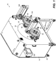
- Figure 1 generally depicts apparatus 10 with a cover and or housing 15.
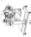
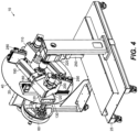
- Figures 2 , 3 , and 4 generally depict apparatus 10 without housing 15. It is understood that apparatus 10 may include a rolling platform 25 although it is also contemplated that other preferred embodiments may not.
- First spindle 50 generally rotates via first drive shaft 80 in communication with an electric powered first direct drive system 110 that is attached to turret 20 first side 30 and second spindle 60 rotates via second drive shaft 100 in communication with an electric powered second direct drive system 120 also attached to turret 20 first side 30.
- Apparatus 10 contemplates that first direct drive system 110 and second direct drive system 120 generally rotate on turret 20 as turret 20 rotates as needed wherein the prior art does not. It is contemplated that first direct drive system 110 and second direct drive system 120 are generally attached via bracket system 130 attached to turret 20 second side 40.
- First direct drive system 110 generally drives first spindle 50 via first drive shaft 80 wherein first direct drive system 110 rotates first drive shaft 80 via first gear reducer 140, which may be but is not limited to a direct drive hollow shaft gear reducer.
- First gear reducer 140 is generally attached to first servo drive 150, first servo motor 160, a single passage rotary union 170, and so forth.
- Second direct drive system 120 generally drives second spindle 60 via second drive shaft 100 wherein second drive system 120 rotates second drive shaft 100 via second gear reducer 180, which may be but is not limited to a direct drive hollow shaft gear reducer.
- Second gear reducer 180 is generally attached to second servo drive 190, second servo motor 200, a single passage rotary union 210, and so forth.
- Turret 20 electric powered main direct drive system 220 includes a multiple and or single passage rotary union 230, a gear reducer 240, a servo drive 250, a servo motor 260, and so forth.
- Turret 20 drive system 220 generally attaches to second side 40 of turret 20 via drift shaft 270.
- Apparatus 10 generally contemplates that turret 20 and the attached first direct drive system 110 and attached second direct drive system 120 are rotated via turret 20 drive system 220.
- First direct drive system 110 includes a first automatic control drive 280
- second direct drive system 120 includes a second automatic control drive 290
- turret 20 drive system 220 may include a turret automatic control drive 300, and so forth.
- turret 20 drive system 220 is in a fixed relationship to turret 20 and is adapted to provide power for first direct drive system 110 and attached second direct drive system 120 via slip ring 310. It is understood that although power may be generally from drive system 220, first drive system 110 and second drive system 120 are still independently controlled via master control 330.
- Master control 330 is a computer which may be a computer interface, a microprocessor, or combinations thereof and so forth for controlling apparatus 10 as desired and as known in the art. It is contemplated that master control 330 may independently selectively rotate first drive system 110, second drive system 120, turret 20 drive system 220 although electrical power may be provided via any one of the respective systems and or independently.
- apparatus 10 generally may be powered electrically as known in the art. It is also understood that apparatus 10 contemplates providing air and an air source for activating cutting mechanisms 340 as known in the art.
Landscapes
- Engineering & Computer Science (AREA)
- Textile Engineering (AREA)
- Replacement Of Web Rolls (AREA)
- Replacing, Conveying, And Pick-Finding For Filamentary Materials (AREA)
Description
- In general, the present invention relates to an automatic cut and transfer coiler and spooler. More particularly, the present invention provides a new device, system and method of using direct drives attached to the rotating turret to independently operate one or more spindles.
- It is known in the prior art to provide machines that may take a large quantity of a length of material such as wire, tubing, filaments, cable, and so forth from one generally large source to then divide as desired into smaller units for sale and or distribution on either a spool where a drum is utilized to wrap the lengths and or coil the length of material such that no drum and or spool is utilized.
- In the prior art, it is known to use automatic cut and transfer (also known as ACT) coilers and spoolers such that a first spindle is independently rotated to receive the length of material desired and then cut for removal from the machine either in a coil fashion or on a spool. For speed and efficiency, a second spindle also independently rotated may be positioned into place to receive the length of material while the first spindle is cleared from the machine. This allows for continuous use and wrapping of the desired material without the need for stopping.
- First spindle and second spindle are typically mounted perpendicularly on a rotatable turret. This allows a first spindle to be loaded with material while the other second spindle is cleared and or removed from the machine. Once a spindle is cleared, the other spindle, now loaded, is moved into position for clearing and or removal while the other spindle is being loaded again. This is accomplished by rotating the turret.
- Of note, it is required that each spindle be able to rotate independently and it is known to spin according to the material be loaded. By example, it is known to load 304,8 m (1000 feet) of material in a minute on one spindle while the other spindle is essentially idle for unloading. The turret is typically rotated slower and it is known to rotate at 5 to 10 rotations per minute depending on the material being loaded.
- In the prior art, the two spindles are powered independently by two servo motors, respectively, where the servo motors are in a fixed position and typically on a frame that supports the turret and the turret is rotated by a separate motor. The spindles are essentially powered by a belt drive system that allows the spindle motors to stay fixed on the frame and then rotationally power the spindles individually by applying the respective belts. The turret is also driven by a belt. To accomplish the needed rotational movements of the spindles and the turret, the motors must be arranged such that the belts are clear from one another while the spindle motors require a drive transfer pulley cluster. This requires a fairly complicated mechanical power transmission.
- Needless to say, belts have a limited service life and need replacing. In the prior art, most of the unit must be disassembled to replace even just one of the three belts regardless if all three need replacing. Placing belts on pulleys also typically requires the adjustment and positioning of the pulley respective of the application and the drive. Still further, belts require tensioning as they become more lax with use. This requires the use of at least two belt tensioners if not three. Document
WO2004/071922 discloses a yarn winder comprising a driven turret with separately driven spindles. The power is delivered directly to the drives of the spindles via a slip ring. - The current state of the art automatic cut and transfer coilers and spoolers clearly have room for improvement and attempts at improvements to the associated deficiencies have not provided the desired solutions. Thus, there is a need for an apparatus, process and or system that provides a direct drive for one or more spindles associated with turret type coilers and spoolers. The above discussed limitations in the prior art is not exhaustive. The current invention provides an inexpensive, time saving, more reliable apparatus, method and system for use with a turret coiler and spooler where the prior art fails.
- In view of the foregoing disadvantages inherent in the known types of automatic cut and transfer coiler and spooler systems now present in the prior art, the present invention provides a new and improved apparatus, system, and method of using. As such, the general purpose of the present invention, which will be described subsequently in greater detail, is to provide a new direct drive automatic cut and transfer coiler and spooler systems, which has all the advantages of the prior art devices and none and or fewer of the disadvantages.
- The invention provides an automatic cut and transfer coiler and spooler according to claim 1.
- There has thus been outlined, rather broadly, the more important features of the invention in order that the detailed description thereof that follows may be better understood and in order that the present contribution to the art may be better appreciated. There are, of course, additional features of the invention that will be described hereinafter and which will form the subject matter of the claims appended hereto.
- In this respect, before explaining at least one embodiment of the invention in detail, it is to be understood that the invention is not limited in this application to the details of construction and to the arrangements of the components set forth in the following description or illustrated in the drawings. The invention is capable of other embodiments and of being practiced and carried out in various ways. Also, it is to be understood that the phraseology and terminology employed herein are for the purpose of description and should not be regarded as limiting. As such, those skilled in the art will appreciate that the conception upon which this disclosure is based may readily be utilized as a basis for the designing of other structures, methods and systems for carrying out the several purposes of the present invention. It is important, therefore, that the claims be regarded as including such equivalent constructions insofar as they do not depart from the scope of the present invention.
- Further, the purpose of the foregoing abstract is to enable the public generally, and especially the engineers and practitioners in the art who are not familiar with patent or legal terms or phraseology, to determine quickly from a cursory inspection the nature and essence of the technical disclosure of the application. The abstract is neither intended to define the invention of the application, which is measured by the claims, nor is it intended to be limiting as to the scope of the invention in any way.
- Therefore, it is an object of the present invention to provide a new and improved automatic cut and transfer coiler and spooler for use in transferring lengths of material, cables, wires, tubing and so forth from one large source location to other smaller units for sale and or distribution.
- Furthermore, an object of the present invention is to provide a new and improved automatic cut and transfer coiler and spooler apparatus, system and method, which allows for an independent direct drive for each spindle and or turret.
- Another object of the present invention is to provide a new and improved automatic cut and transfer coiler and spooler, which does not require a drive transfer pulley system and or will not require a belt drive system for the spindles and or the turret while still providing independent rotation of the individual spindles around their own respective axis and or turret.
- It is a further object of the present invention to provide a new and improved automatic cut and transfer coiler and spooler apparatus, system and method, which is of a durable and reliable construction leading to a more robust unit.
- An even further object of the present invention is to provide a new and improved automatic cut and transfer coiler and spooler apparatus, system and method, which is susceptible to a low cost of installation and labor, which accordingly is then susceptible to low prices of sale to the consuming industry, thereby making such a system economically available to those in the field.
- Still another object of the present invention is to provide a new and improved automatic cut and transfer coiler and spooler apparatus, system and method, which provides all of the advantages of the prior art while simultaneously overcoming some of the disadvantages normally associated therewith.
- Yet still another object of the present invention is to provide a new and improved automatic cut and transfer coiler and spooler apparatus, system and method, which eliminates belt drives.
- These, together with other objects of the invention, along with the various features of novelty, which characterize the invention, are pointed out with particularity in the claims annexed to and forming a part of this disclosure. For a better understanding of the invention, its operating advantages, and the specific objects attained by its uses, reference should be had to the accompanying drawings and descriptive matter in which there are illustrated preferred embodiments of the invention.
- The invention will be better understood and objects other than those set forth above will become apparent when consideration is given to the following detailed description thereof. Such description makes reference to the annexed pictorial illustrations, graphs, drawings and appendices.
-
Figure 1 is a general perspective front view illustration including a housing of a preferred embodiment in accordance with the current invention. -
Figure 2 is a general top cutaway illustration of the same general embodiment inFigure 1 in accordance with a preferred embodiment of the current invention. -
Figure 3 is a general perspective first back view illustration of the same general embodiment ofFigure 1 without the housing in accordance with a preferred embodiment of the current invention. -
Figure 4 is a general perspective second back view illustration of the same general embodiment ofFigure 1 without the housing in accordance with a preferred embodiment of the current invention. - Referring to the illustrations, drawings, and pictures, and to
Figure 1 in particular,reference character 10 generally designates a new and improved automatic cut and transfer coiler and spooler apparatus, system and method of using same constructed in accordance with the present invention. For purposes of convenience, thereference numeral 10 may generally be utilized for the indication of preferred embodiments of the invention.Apparatus 10 is generally used in coiling and spooling operations, which may or may not include automatic cutting. - Now referring to the figures and more specifically
Figures 2 ,3 , and4 ,apparatus 10 includes aturret 20 having afirst side 30 and asecond side 40 whereinfirst side 30 may have afirst spindle 50 and or asecond spindle 60.Turret 20 generally has afirst aperture 70 for afirst drive shaft 80 to communicate from saidfirst side 30 to saidsecond side 40.Turret 20 generally has asecond aperture 90 for asecond drive shaft 100 to communicate from saidfirst side 30 to saidsecond side 40. - Of note,
Figure 1 generally depictsapparatus 10 with a cover and orhousing 15.Figures 2 ,3 , and4 generally depictapparatus 10 withouthousing 15. It is understood thatapparatus 10 may include a rollingplatform 25 although it is also contemplated that other preferred embodiments may not. -
First spindle 50 generally rotates viafirst drive shaft 80 in communication with an electric powered firstdirect drive system 110 that is attached to turret 20first side 30 andsecond spindle 60 rotates viasecond drive shaft 100 in communication with an electric powered seconddirect drive system 120 also attached to turret 20first side 30. -
Apparatus 10 contemplates that firstdirect drive system 110 and seconddirect drive system 120 generally rotate onturret 20 asturret 20 rotates as needed wherein the prior art does not. It is contemplated that firstdirect drive system 110 and seconddirect drive system 120 are generally attached viabracket system 130 attached to turret 20second side 40. - First
direct drive system 110 generally drivesfirst spindle 50 viafirst drive shaft 80 wherein firstdirect drive system 110 rotatesfirst drive shaft 80 viafirst gear reducer 140, which may be but is not limited to a direct drive hollow shaft gear reducer.First gear reducer 140 is generally attached tofirst servo drive 150,first servo motor 160, a singlepassage rotary union 170, and so forth. - Second
direct drive system 120 generally drivessecond spindle 60 viasecond drive shaft 100 whereinsecond drive system 120 rotatessecond drive shaft 100 viasecond gear reducer 180, which may be but is not limited to a direct drive hollow shaft gear reducer.Second gear reducer 180 is generally attached tosecond servo drive 190,second servo motor 200, a singlepassage rotary union 210, and so forth. -
Turret 20 electric powered maindirect drive system 220 includes a multiple and or singlepassage rotary union 230, agear reducer 240, aservo drive 250, aservo motor 260, and so forth.Turret 20drive system 220 generally attaches tosecond side 40 ofturret 20 viadrift shaft 270.Apparatus 10 generally contemplates thatturret 20 and the attached firstdirect drive system 110 and attached seconddirect drive system 120 are rotated viaturret 20drive system 220. - First
direct drive system 110 includes a firstautomatic control drive 280, seconddirect drive system 120 includes a secondautomatic control drive 290,turret 20drive system 220 may include a turretautomatic control drive 300, and so forth. According to the invention, in theapparatus 10,turret 20drive system 220 is in a fixed relationship to turret 20 and is adapted to provide power for firstdirect drive system 110 and attached seconddirect drive system 120 viaslip ring 310. It is understood that although power may be generally fromdrive system 220,first drive system 110 andsecond drive system 120 are still independently controlled viamaster control 330. -
Master control 330 is a computer which may be a computer interface, a microprocessor, or combinations thereof and so forth for controllingapparatus 10 as desired and as known in the art. It is contemplated thatmaster control 330 may independently selectively rotatefirst drive system 110,second drive system 120,turret 20drive system 220 although electrical power may be provided via any one of the respective systems and or independently. - It is understood that
apparatus 10 generally may be powered electrically as known in the art. It is also understood thatapparatus 10 contemplates providing air and an air source for activatingcutting mechanisms 340 as known in the art.
Claims (1)
- An automatic cut and transfer coiler and spooler (10) comprising:a turret (20) having a first side (30), a second side (40), and said turret is adapted to selectively and independently rotate via a main direct drive system (220) connected to said second side;a first spindle (50) attached to said first side of said turret and adapted to selectively and independently rotate for coiling and spooling via a first independent direct drive system (110) attached to said second side of said turret and in communication with said first spindle;a second spindle (60) attached to said first side of said turret and adapted to selectively and independently rotate for coiling and spooling via a second independent direct drive system (120) attached to said second side of said turret and in communication with said second spindle; anda master control computer (330) in communication with said main direct drive system, said first independent drive system, and said second independent drive system for selectively and independently rotating said turret, said first spindle, and said second spindle respectively, whereinthe main direct drive system (220) is in a fixed relationship to the turret (20) and is adapted to provide power to the first direct drive system (110) and the second direct drive system (120) via a slip ring (310).
Applications Claiming Priority (3)
| Application Number | Priority Date | Filing Date | Title |
|---|---|---|---|
| US201662295206P | 2016-02-15 | 2016-02-15 | |
| US15/432,856 US20170233215A1 (en) | 2016-02-15 | 2017-02-14 | Automatic cut and transfer coiler and or spooler |
| PCT/US2017/000013 WO2017142631A1 (en) | 2016-02-15 | 2017-02-15 | Automatic cut and transfer coiler and or spooler |
Publications (3)
| Publication Number | Publication Date |
|---|---|
| EP3416907A1 EP3416907A1 (en) | 2018-12-26 |
| EP3416907A4 EP3416907A4 (en) | 2019-10-16 |
| EP3416907B1 true EP3416907B1 (en) | 2024-04-03 |
Family
ID=59560561
Family Applications (1)
| Application Number | Title | Priority Date | Filing Date |
|---|---|---|---|
| EP17753601.8A Active EP3416907B1 (en) | 2016-02-15 | 2017-02-15 | Automatic cut and transfer coiler and or spooler |
Country Status (5)
| Country | Link |
|---|---|
| US (5) | US20170233215A1 (en) |
| EP (1) | EP3416907B1 (en) |
| CN (1) | CN108602641A (en) |
| DK (1) | DK3416907T3 (en) |
| WO (1) | WO2017142631A1 (en) |
Families Citing this family (4)
| Publication number | Priority date | Publication date | Assignee | Title |
|---|---|---|---|---|
| US20170233215A1 (en) | 2016-02-15 | 2017-08-17 | Reel Power Licensing Corp. | Automatic cut and transfer coiler and or spooler |
| US10647540B2 (en) * | 2017-12-21 | 2020-05-12 | Reel Power Licensing Corp. | Low tension application coiler |
| US12280981B2 (en) | 2021-09-29 | 2025-04-22 | Windak Holding Ab | Automated filament spooler |
| CN114920081B (en) * | 2022-06-08 | 2024-12-27 | 天津杰斯锐尔智能科技有限公司 | A fire-fighting cable winding device for buildings |
Citations (2)
| Publication number | Priority date | Publication date | Assignee | Title |
|---|---|---|---|---|
| WO2004071922A1 (en) * | 2003-02-12 | 2004-08-26 | Tstm Co., Ltd. | Rotation detection device of yarn winding apparatus |
| DE102006018820A1 (en) * | 2006-04-22 | 2007-10-25 | Saurer Gmbh & Co. Kg | Thread winding device, has actuators coupled with stationary controller by rotatable transducer, which has sliding contact points between rotor and stator, where rotor is formed by flat contact disc having circulating angle markings |
Family Cites Families (28)
| Publication number | Priority date | Publication date | Assignee | Title |
|---|---|---|---|---|
| US4033519A (en) * | 1974-06-06 | 1977-07-05 | Teijin Limited | Method and apparatus for automatically changing bobbins and winding yarn continuously |
| DE2655544C2 (en) * | 1976-12-08 | 1978-07-20 | Barmag Barmer Maschinenfabrik Ag, 5630 Remscheid | Spooling device with peripheral drive for spooling man-made fibers |
| GB8415732D0 (en) * | 1984-06-20 | 1984-07-25 | Bicc Plc | Winding apparatus |
| US5156347A (en) * | 1988-03-30 | 1992-10-20 | Gay Ii Francis V | Automatic continuous fiber winder |
| US5012985A (en) * | 1989-04-10 | 1991-05-07 | Davis Electric Wallingford Corporation | Multiple station turret winding apparatus and method for winding wire onto reels |
| US4951889A (en) * | 1989-06-12 | 1990-08-28 | Epm Corporation | Programmable perfect layer winding system |
| JP3147258B2 (en) * | 1992-12-12 | 2001-03-19 | 帝人製機株式会社 | Yarn winding device |
| TW483866B (en) | 1997-03-25 | 2002-04-21 | Barmag Barmer Maschf | Method of winding an advancing yarn and takeup machine for carrying out such method |
| TR199800797A2 (en) | 1997-05-15 | 1998-12-21 | Barmag Ag | A method for winding a traveling thread. |
| DE19827941A1 (en) * | 1997-06-26 | 1999-01-07 | Barmag Barmer Maschf | Method for changing bobbin at winding station |
| DE19832811A1 (en) | 1997-07-26 | 1999-01-28 | Barmag Barmer Maschf | Bobbin winding method |
| US6015113A (en) * | 1997-10-06 | 2000-01-18 | E. I. Du Pont De Nemours And Company | Winder for synthetic filaments |
| DE29908962U1 (en) * | 1999-05-21 | 1999-09-02 | Neumag - Neumünstersche Maschinen- und Anlagenbau GmbH, 24536 Neumünster | Winding machine |
| DE10224033A1 (en) * | 2002-05-31 | 2003-12-11 | Barmag Barmer Maschf | Synthetic thread bobbin winder machine has operation monitored by control panel with light emitting diodes linked to actuators for pre start-up checks |
| JP4293460B2 (en) * | 2005-12-20 | 2009-07-08 | Ykk株式会社 | Wire rod winding device |
| WO2007128499A1 (en) | 2006-05-08 | 2007-11-15 | Oerlikon Textile Gmbh & Co. Kg | Spinning, drawing and texturing machine |
| US7887004B2 (en) * | 2008-05-30 | 2011-02-15 | Baugher Robert C | Modular automatic non-turret winder |
| CN102009874A (en) * | 2010-11-16 | 2011-04-13 | 北京中丽制机工程技术有限公司 | Control method of turntable-driven device of winder |
| DE102012001849A1 (en) | 2011-02-04 | 2012-08-09 | Hardy Zissel | Method for fixing UHF radio frequency identification transponder within plastic-made drink barrel collar, involves accommodating barrels within collar by spacer made up of porous material and providing fixing element to fix transponder |
| DE102012107015A1 (en) * | 2011-08-03 | 2013-02-07 | Oerlikon Textile Gmbh & Co. Kg | spooling |
| DE102011115051A1 (en) | 2011-10-07 | 2013-04-11 | Oerlikon Textile Gmbh & Co. Kg | Method for continuous winding of band-shaped spool good e.g. thread, to coil, involves slowing down one of spools for trapping band-shaped spool good in trap device in trap position and/or holding spool in stop condition |
| DE102011116156A1 (en) | 2011-10-14 | 2013-04-18 | Oerlikon Textile Gmbh & Co. Kg | Method and device for the continuous winding of a strand-like material to be spooled |
| DE102012018491A1 (en) * | 2011-10-15 | 2013-04-18 | Oerlikon Textile Gmbh & Co. Kg | Winding machine for continuous rolling of thread to solid coil, has finite synthetic foil strip that is wound at final winding portion of solid coil along with thread for fixation of thread end at solid coil |
| WO2013167450A1 (en) | 2012-05-11 | 2013-11-14 | Oerlikon Textile Gmbh & Co. Kg | Method and device for continuously winding a thread |
| US20170233215A1 (en) * | 2016-02-15 | 2017-08-17 | Reel Power Licensing Corp. | Automatic cut and transfer coiler and or spooler |
| US10358316B2 (en) * | 2017-03-21 | 2019-07-23 | Reelex Packaging Solutions, Inc. | Apparatus and methods for winding and cutting wire or cable |
| US10647540B2 (en) * | 2017-12-21 | 2020-05-12 | Reel Power Licensing Corp. | Low tension application coiler |
| DE102019116207A1 (en) * | 2019-06-14 | 2020-12-17 | Georg Sahm Gmbh & Co. Kg | Bobbin transport vehicle, winding machine system, method for exchanging a bobbin for a bobbin tube on a winding machine and software with control logic |
-
2017
- 2017-02-14 US US15/432,856 patent/US20170233215A1/en not_active Abandoned
- 2017-02-15 DK DK17753601.8T patent/DK3416907T3/en active
- 2017-02-15 EP EP17753601.8A patent/EP3416907B1/en active Active
- 2017-02-15 CN CN201780010471.2A patent/CN108602641A/en active Pending
- 2017-02-15 WO PCT/US2017/000013 patent/WO2017142631A1/en not_active Ceased
-
2019
- 2019-10-31 US US16/670,250 patent/US11014774B2/en active Active
-
2021
- 2021-04-26 US US17/240,207 patent/US11548753B2/en active Active
-
2022
- 2022-12-06 US US18/075,644 patent/US11919739B2/en active Active
-
2024
- 2024-01-31 US US18/428,724 patent/US12606411B2/en active Active
Patent Citations (2)
| Publication number | Priority date | Publication date | Assignee | Title |
|---|---|---|---|---|
| WO2004071922A1 (en) * | 2003-02-12 | 2004-08-26 | Tstm Co., Ltd. | Rotation detection device of yarn winding apparatus |
| DE102006018820A1 (en) * | 2006-04-22 | 2007-10-25 | Saurer Gmbh & Co. Kg | Thread winding device, has actuators coupled with stationary controller by rotatable transducer, which has sliding contact points between rotor and stator, where rotor is formed by flat contact disc having circulating angle markings |
Also Published As
| Publication number | Publication date |
|---|---|
| US12606411B2 (en) | 2026-04-21 |
| US20240166467A1 (en) | 2024-05-23 |
| DK3416907T3 (en) | 2024-05-06 |
| US20210245990A1 (en) | 2021-08-12 |
| US20170233215A1 (en) | 2017-08-17 |
| CN108602641A (en) | 2018-09-28 |
| EP3416907A4 (en) | 2019-10-16 |
| US11014774B2 (en) | 2021-05-25 |
| US20200062533A1 (en) | 2020-02-27 |
| US11919739B2 (en) | 2024-03-05 |
| US20230107701A1 (en) | 2023-04-06 |
| EP3416907A1 (en) | 2018-12-26 |
| US11548753B2 (en) | 2023-01-10 |
| WO2017142631A1 (en) | 2017-08-24 |
Similar Documents
| Publication | Publication Date | Title |
|---|---|---|
| US12606411B2 (en) | Automatic cut and transfer coiler and or spooler | |
| CN105917047B (en) | Wire twisting machine | |
| US6735933B2 (en) | Method and apparatus for axial feed of ribbon material | |
| US11155938B2 (en) | Wire stranding apparatus and method for manufacturing stranded wire | |
| US7896278B2 (en) | Winding apparatus | |
| CN103832883B (en) | Synchronous winding device | |
| US3094833A (en) | Multi-strand cable fabricating apparatus and method | |
| EP1053967A1 (en) | Winder | |
| CN106800224B (en) | A kind of unmanned plane list drives cable pulling-pushing device | |
| US6726142B2 (en) | Twist controlling device, rotatable nip and axial feed system | |
| US2484055A (en) | Core replacing apparatus and method for stranded cables | |
| CN210594537U (en) | Strip tension control device | |
| CN209035139U (en) | Unlubricated reinforcing bar draw-off gear | |
| US11198954B2 (en) | Yarn twisting machine | |
| US2272192A (en) | Wire drawing machine | |
| CN206735540U (en) | A kind of unmanned plane list drives cable pulling-pushing device | |
| CN106335821A (en) | Mechanical hydraulically-driven cable winding device | |
| KR100888083B1 (en) | Insulated Wire Manufacturing Equipment | |
| KR101323327B1 (en) | Multiplex wrapping machine for insulation of superconducting wire | |
| JPH02232156A (en) | Wire tension holding method in wire type cutter | |
| CN106892306A (en) | A kind of cable collection device | |
| JPH08180753A (en) | Stranding machine | |
| JPH05338116A (en) | Spiral marking device of electric wire | |
| JPS6336919A (en) | Carousel reel | |
| WO1995004185A1 (en) | Apparatus for and a method of applying an elongate element in a double twist stranding machine or buncher |
Legal Events
| Date | Code | Title | Description |
|---|---|---|---|
| STAA | Information on the status of an ep patent application or granted ep patent |
Free format text: STATUS: THE INTERNATIONAL PUBLICATION HAS BEEN MADE |
|
| PUAI | Public reference made under article 153(3) epc to a published international application that has entered the european phase |
Free format text: ORIGINAL CODE: 0009012 |
|
| STAA | Information on the status of an ep patent application or granted ep patent |
Free format text: STATUS: REQUEST FOR EXAMINATION WAS MADE |
|
| 17P | Request for examination filed |
Effective date: 20180720 |
|
| AK | Designated contracting states |
Kind code of ref document: A1 Designated state(s): AL AT BE BG CH CY CZ DE DK EE ES FI FR GB GR HR HU IE IS IT LI LT LU LV MC MK MT NL NO PL PT RO RS SE SI SK SM TR |
|
| AX | Request for extension of the european patent |
Extension state: BA ME |
|
| DAV | Request for validation of the european patent (deleted) | ||
| DAX | Request for extension of the european patent (deleted) | ||
| A4 | Supplementary search report drawn up and despatched |
Effective date: 20190918 |
|
| RIC1 | Information provided on ipc code assigned before grant |
Ipc: B65H 54/24 20060101AFI20190912BHEP Ipc: B65H 67/048 20060101ALI20190912BHEP Ipc: B65H 54/74 20060101ALI20190912BHEP |
|
| STAA | Information on the status of an ep patent application or granted ep patent |
Free format text: STATUS: EXAMINATION IS IN PROGRESS |
|
| 17Q | First examination report despatched |
Effective date: 20210519 |
|
| GRAP | Despatch of communication of intention to grant a patent |
Free format text: ORIGINAL CODE: EPIDOSNIGR1 |
|
| STAA | Information on the status of an ep patent application or granted ep patent |
Free format text: STATUS: GRANT OF PATENT IS INTENDED |
|
| INTG | Intention to grant announced |
Effective date: 20231024 |
|
| P01 | Opt-out of the competence of the unified patent court (upc) registered |
Effective date: 20231116 |
|
| GRAS | Grant fee paid |
Free format text: ORIGINAL CODE: EPIDOSNIGR3 |
|
| GRAA | (expected) grant |
Free format text: ORIGINAL CODE: 0009210 |
|
| STAA | Information on the status of an ep patent application or granted ep patent |
Free format text: STATUS: THE PATENT HAS BEEN GRANTED |
|
| AK | Designated contracting states |
Kind code of ref document: B1 Designated state(s): AL AT BE BG CH CY CZ DE DK EE ES FI FR GB GR HR HU IE IS IT LI LT LU LV MC MK MT NL NO PL PT RO RS SE SI SK SM TR |
|
| REG | Reference to a national code |
Ref country code: GB Ref legal event code: FG4D |
|
| REG | Reference to a national code |
Ref country code: CH Ref legal event code: EP |
|
| REG | Reference to a national code |
Ref country code: IE Ref legal event code: FG4D Ref country code: NL Ref legal event code: FP |
|
| REG | Reference to a national code |
Ref country code: DE Ref legal event code: R096 Ref document number: 602017080607 Country of ref document: DE |
|
| REG | Reference to a national code |
Ref country code: DK Ref legal event code: T3 Effective date: 20240502 |
|
| REG | Reference to a national code |
Ref country code: LT Ref legal event code: MG9D |
|
| REG | Reference to a national code |
Ref country code: AT Ref legal event code: MK05 Ref document number: 1672113 Country of ref document: AT Kind code of ref document: T Effective date: 20240403 |
|
| PG25 | Lapsed in a contracting state [announced via postgrant information from national office to epo] |
Ref country code: IS Free format text: LAPSE BECAUSE OF FAILURE TO SUBMIT A TRANSLATION OF THE DESCRIPTION OR TO PAY THE FEE WITHIN THE PRESCRIBED TIME-LIMIT Effective date: 20240803 |
|
| PG25 | Lapsed in a contracting state [announced via postgrant information from national office to epo] |
Ref country code: BG Free format text: LAPSE BECAUSE OF FAILURE TO SUBMIT A TRANSLATION OF THE DESCRIPTION OR TO PAY THE FEE WITHIN THE PRESCRIBED TIME-LIMIT Effective date: 20240403 |
|
| PG25 | Lapsed in a contracting state [announced via postgrant information from national office to epo] |
Ref country code: HR Free format text: LAPSE BECAUSE OF FAILURE TO SUBMIT A TRANSLATION OF THE DESCRIPTION OR TO PAY THE FEE WITHIN THE PRESCRIBED TIME-LIMIT Effective date: 20240403 Ref country code: FI Free format text: LAPSE BECAUSE OF FAILURE TO SUBMIT A TRANSLATION OF THE DESCRIPTION OR TO PAY THE FEE WITHIN THE PRESCRIBED TIME-LIMIT Effective date: 20240403 |
|
| PG25 | Lapsed in a contracting state [announced via postgrant information from national office to epo] |
Ref country code: GR Free format text: LAPSE BECAUSE OF FAILURE TO SUBMIT A TRANSLATION OF THE DESCRIPTION OR TO PAY THE FEE WITHIN THE PRESCRIBED TIME-LIMIT Effective date: 20240704 |
|
| PG25 | Lapsed in a contracting state [announced via postgrant information from national office to epo] |
Ref country code: PT Free format text: LAPSE BECAUSE OF FAILURE TO SUBMIT A TRANSLATION OF THE DESCRIPTION OR TO PAY THE FEE WITHIN THE PRESCRIBED TIME-LIMIT Effective date: 20240805 |
|
| PG25 | Lapsed in a contracting state [announced via postgrant information from national office to epo] |
Ref country code: ES Free format text: LAPSE BECAUSE OF FAILURE TO SUBMIT A TRANSLATION OF THE DESCRIPTION OR TO PAY THE FEE WITHIN THE PRESCRIBED TIME-LIMIT Effective date: 20240403 |
|
| PG25 | Lapsed in a contracting state [announced via postgrant information from national office to epo] |
Ref country code: CZ Free format text: LAPSE BECAUSE OF FAILURE TO SUBMIT A TRANSLATION OF THE DESCRIPTION OR TO PAY THE FEE WITHIN THE PRESCRIBED TIME-LIMIT Effective date: 20240403 |
|
| PG25 | Lapsed in a contracting state [announced via postgrant information from national office to epo] |
Ref country code: AT Free format text: LAPSE BECAUSE OF FAILURE TO SUBMIT A TRANSLATION OF THE DESCRIPTION OR TO PAY THE FEE WITHIN THE PRESCRIBED TIME-LIMIT Effective date: 20240403 |
|
| PG25 | Lapsed in a contracting state [announced via postgrant information from national office to epo] |
Ref country code: PL Free format text: LAPSE BECAUSE OF FAILURE TO SUBMIT A TRANSLATION OF THE DESCRIPTION OR TO PAY THE FEE WITHIN THE PRESCRIBED TIME-LIMIT Effective date: 20240403 |
|
| PG25 | Lapsed in a contracting state [announced via postgrant information from national office to epo] |
Ref country code: LV Free format text: LAPSE BECAUSE OF FAILURE TO SUBMIT A TRANSLATION OF THE DESCRIPTION OR TO PAY THE FEE WITHIN THE PRESCRIBED TIME-LIMIT Effective date: 20240403 |
|
| PG25 | Lapsed in a contracting state [announced via postgrant information from national office to epo] |
Ref country code: PT Free format text: LAPSE BECAUSE OF FAILURE TO SUBMIT A TRANSLATION OF THE DESCRIPTION OR TO PAY THE FEE WITHIN THE PRESCRIBED TIME-LIMIT Effective date: 20240805 Ref country code: PL Free format text: LAPSE BECAUSE OF FAILURE TO SUBMIT A TRANSLATION OF THE DESCRIPTION OR TO PAY THE FEE WITHIN THE PRESCRIBED TIME-LIMIT Effective date: 20240403 Ref country code: LV Free format text: LAPSE BECAUSE OF FAILURE TO SUBMIT A TRANSLATION OF THE DESCRIPTION OR TO PAY THE FEE WITHIN THE PRESCRIBED TIME-LIMIT Effective date: 20240403 Ref country code: IS Free format text: LAPSE BECAUSE OF FAILURE TO SUBMIT A TRANSLATION OF THE DESCRIPTION OR TO PAY THE FEE WITHIN THE PRESCRIBED TIME-LIMIT Effective date: 20240803 Ref country code: HR Free format text: LAPSE BECAUSE OF FAILURE TO SUBMIT A TRANSLATION OF THE DESCRIPTION OR TO PAY THE FEE WITHIN THE PRESCRIBED TIME-LIMIT Effective date: 20240403 Ref country code: GR Free format text: LAPSE BECAUSE OF FAILURE TO SUBMIT A TRANSLATION OF THE DESCRIPTION OR TO PAY THE FEE WITHIN THE PRESCRIBED TIME-LIMIT Effective date: 20240704 Ref country code: FI Free format text: LAPSE BECAUSE OF FAILURE TO SUBMIT A TRANSLATION OF THE DESCRIPTION OR TO PAY THE FEE WITHIN THE PRESCRIBED TIME-LIMIT Effective date: 20240403 Ref country code: ES Free format text: LAPSE BECAUSE OF FAILURE TO SUBMIT A TRANSLATION OF THE DESCRIPTION OR TO PAY THE FEE WITHIN THE PRESCRIBED TIME-LIMIT Effective date: 20240403 Ref country code: CZ Free format text: LAPSE BECAUSE OF FAILURE TO SUBMIT A TRANSLATION OF THE DESCRIPTION OR TO PAY THE FEE WITHIN THE PRESCRIBED TIME-LIMIT Effective date: 20240403 Ref country code: BG Free format text: LAPSE BECAUSE OF FAILURE TO SUBMIT A TRANSLATION OF THE DESCRIPTION OR TO PAY THE FEE WITHIN THE PRESCRIBED TIME-LIMIT Effective date: 20240403 Ref country code: AT Free format text: LAPSE BECAUSE OF FAILURE TO SUBMIT A TRANSLATION OF THE DESCRIPTION OR TO PAY THE FEE WITHIN THE PRESCRIBED TIME-LIMIT Effective date: 20240403 Ref country code: RS Free format text: LAPSE BECAUSE OF FAILURE TO SUBMIT A TRANSLATION OF THE DESCRIPTION OR TO PAY THE FEE WITHIN THE PRESCRIBED TIME-LIMIT Effective date: 20240703 |
|
| REG | Reference to a national code |
Ref country code: DE Ref legal event code: R097 Ref document number: 602017080607 Country of ref document: DE |
|
| PG25 | Lapsed in a contracting state [announced via postgrant information from national office to epo] |
Ref country code: EE Free format text: LAPSE BECAUSE OF FAILURE TO SUBMIT A TRANSLATION OF THE DESCRIPTION OR TO PAY THE FEE WITHIN THE PRESCRIBED TIME-LIMIT Effective date: 20240403 |
|
| PG25 | Lapsed in a contracting state [announced via postgrant information from national office to epo] |
Ref country code: SK Free format text: LAPSE BECAUSE OF FAILURE TO SUBMIT A TRANSLATION OF THE DESCRIPTION OR TO PAY THE FEE WITHIN THE PRESCRIBED TIME-LIMIT Effective date: 20240403 Ref country code: RO Free format text: LAPSE BECAUSE OF FAILURE TO SUBMIT A TRANSLATION OF THE DESCRIPTION OR TO PAY THE FEE WITHIN THE PRESCRIBED TIME-LIMIT Effective date: 20240403 |
|
| PG25 | Lapsed in a contracting state [announced via postgrant information from national office to epo] |
Ref country code: SM Free format text: LAPSE BECAUSE OF FAILURE TO SUBMIT A TRANSLATION OF THE DESCRIPTION OR TO PAY THE FEE WITHIN THE PRESCRIBED TIME-LIMIT Effective date: 20240403 |
|
| PG25 | Lapsed in a contracting state [announced via postgrant information from national office to epo] |
Ref country code: SM Free format text: LAPSE BECAUSE OF FAILURE TO SUBMIT A TRANSLATION OF THE DESCRIPTION OR TO PAY THE FEE WITHIN THE PRESCRIBED TIME-LIMIT Effective date: 20240403 Ref country code: SK Free format text: LAPSE BECAUSE OF FAILURE TO SUBMIT A TRANSLATION OF THE DESCRIPTION OR TO PAY THE FEE WITHIN THE PRESCRIBED TIME-LIMIT Effective date: 20240403 Ref country code: RO Free format text: LAPSE BECAUSE OF FAILURE TO SUBMIT A TRANSLATION OF THE DESCRIPTION OR TO PAY THE FEE WITHIN THE PRESCRIBED TIME-LIMIT Effective date: 20240403 Ref country code: EE Free format text: LAPSE BECAUSE OF FAILURE TO SUBMIT A TRANSLATION OF THE DESCRIPTION OR TO PAY THE FEE WITHIN THE PRESCRIBED TIME-LIMIT Effective date: 20240403 |
|
| PLBE | No opposition filed within time limit |
Free format text: ORIGINAL CODE: 0009261 |
|
| STAA | Information on the status of an ep patent application or granted ep patent |
Free format text: STATUS: NO OPPOSITION FILED WITHIN TIME LIMIT |
|
| 26N | No opposition filed |
Effective date: 20250106 |
|
| PG25 | Lapsed in a contracting state [announced via postgrant information from national office to epo] |
Ref country code: SI Free format text: LAPSE BECAUSE OF FAILURE TO SUBMIT A TRANSLATION OF THE DESCRIPTION OR TO PAY THE FEE WITHIN THE PRESCRIBED TIME-LIMIT Effective date: 20240403 |
|
| PG25 | Lapsed in a contracting state [announced via postgrant information from national office to epo] |
Ref country code: SE Free format text: LAPSE BECAUSE OF FAILURE TO SUBMIT A TRANSLATION OF THE DESCRIPTION OR TO PAY THE FEE WITHIN THE PRESCRIBED TIME-LIMIT Effective date: 20240403 |
|
| PG25 | Lapsed in a contracting state [announced via postgrant information from national office to epo] |
Ref country code: MC Free format text: LAPSE BECAUSE OF FAILURE TO SUBMIT A TRANSLATION OF THE DESCRIPTION OR TO PAY THE FEE WITHIN THE PRESCRIBED TIME-LIMIT Effective date: 20240403 |
|
| REG | Reference to a national code |
Ref country code: CH Ref legal event code: PL |
|
| PG25 | Lapsed in a contracting state [announced via postgrant information from national office to epo] |
Ref country code: LU Free format text: LAPSE BECAUSE OF NON-PAYMENT OF DUE FEES Effective date: 20250215 |
|
| PG25 | Lapsed in a contracting state [announced via postgrant information from national office to epo] |
Ref country code: CH Free format text: LAPSE BECAUSE OF NON-PAYMENT OF DUE FEES Effective date: 20250228 |
|
| REG | Reference to a national code |
Ref country code: BE Ref legal event code: MM Effective date: 20250228 |
|
| PG25 | Lapsed in a contracting state [announced via postgrant information from national office to epo] |
Ref country code: BE Free format text: LAPSE BECAUSE OF NON-PAYMENT OF DUE FEES Effective date: 20250228 |
|
| PG25 | Lapsed in a contracting state [announced via postgrant information from national office to epo] |
Ref country code: IE Free format text: LAPSE BECAUSE OF NON-PAYMENT OF DUE FEES Effective date: 20250215 |
|
| PG25 | Lapsed in a contracting state [announced via postgrant information from national office to epo] |
Ref country code: IT Free format text: LAPSE BECAUSE OF FAILURE TO SUBMIT A TRANSLATION OF THE DESCRIPTION OR TO PAY THE FEE WITHIN THE PRESCRIBED TIME-LIMIT Effective date: 20240403 |
|
| PGFP | Annual fee paid to national office [announced via postgrant information from national office to epo] |
Ref country code: NL Payment date: 20260218 Year of fee payment: 10 |
|
| PGFP | Annual fee paid to national office [announced via postgrant information from national office to epo] |
Ref country code: GB Payment date: 20260226 Year of fee payment: 10 |
|
| PGFP | Annual fee paid to national office [announced via postgrant information from national office to epo] |
Ref country code: NO Payment date: 20260323 Year of fee payment: 10 Ref country code: DE Payment date: 20260225 Year of fee payment: 10 Ref country code: DK Payment date: 20260220 Year of fee payment: 10 |
|
| PGFP | Annual fee paid to national office [announced via postgrant information from national office to epo] |
Ref country code: FR Payment date: 20260219 Year of fee payment: 10 |