EP3416713B1 - Modularer tragbarer sauerstoffgenerator - Google Patents
Modularer tragbarer sauerstoffgenerator Download PDFInfo
- Publication number
- EP3416713B1 EP3416713B1 EP17752812.2A EP17752812A EP3416713B1 EP 3416713 B1 EP3416713 B1 EP 3416713B1 EP 17752812 A EP17752812 A EP 17752812A EP 3416713 B1 EP3416713 B1 EP 3416713B1
- Authority
- EP
- European Patent Office
- Prior art keywords
- cartridge
- oxygen
- opening
- plunger
- modular portable
- Prior art date
- Legal status (The legal status is an assumption and is not a legal conclusion. Google has not performed a legal analysis and makes no representation as to the accuracy of the status listed.)
- Active
Links
Images


Classifications
-
- A—HUMAN NECESSITIES
- A62—LIFE-SAVING; FIRE-FIGHTING
- A62B—DEVICES, APPARATUS OR METHODS FOR LIFE-SAVING
- A62B21/00—Devices for producing oxygen from chemical substances for respiratory apparatus
-
- A—HUMAN NECESSITIES
- A61—MEDICAL OR VETERINARY SCIENCE; HYGIENE
- A61M—DEVICES FOR INTRODUCING MEDIA INTO, OR ONTO, THE BODY; DEVICES FOR TRANSDUCING BODY MEDIA OR FOR TAKING MEDIA FROM THE BODY; DEVICES FOR PRODUCING OR ENDING SLEEP OR STUPOR
- A61M16/00—Devices for influencing the respiratory system of patients by gas treatment, e.g. ventilators; Tracheal tubes
- A61M16/10—Preparation of respiratory gases or vapours
- A61M16/1005—Preparation of respiratory gases or vapours with O2 features or with parameter measurement
- A61M16/101—Preparation of respiratory gases or vapours with O2 features or with parameter measurement using an oxygen concentrator
-
- A—HUMAN NECESSITIES
- A61—MEDICAL OR VETERINARY SCIENCE; HYGIENE
- A61M—DEVICES FOR INTRODUCING MEDIA INTO, OR ONTO, THE BODY; DEVICES FOR TRANSDUCING BODY MEDIA OR FOR TAKING MEDIA FROM THE BODY; DEVICES FOR PRODUCING OR ENDING SLEEP OR STUPOR
- A61M16/00—Devices for influencing the respiratory system of patients by gas treatment, e.g. ventilators; Tracheal tubes
- A61M16/10—Preparation of respiratory gases or vapours
- A61M16/14—Preparation of respiratory gases or vapours by mixing different fluids, one of them being in a liquid phase
- A61M16/16—Devices to humidify the respiration air
-
- F—MECHANICAL ENGINEERING; LIGHTING; HEATING; WEAPONS; BLASTING
- F17—STORING OR DISTRIBUTING GASES OR LIQUIDS
- F17C—VESSELS FOR CONTAINING OR STORING COMPRESSED, LIQUEFIED OR SOLIDIFIED GASES; FIXED-CAPACITY GAS-HOLDERS; FILLING VESSELS WITH, OR DISCHARGING FROM VESSELS, COMPRESSED, LIQUEFIED, OR SOLIDIFIED GASES
- F17C1/00—Pressure vessels, e.g. gas cylinder, gas tank, replaceable cartridge
-
- F—MECHANICAL ENGINEERING; LIGHTING; HEATING; WEAPONS; BLASTING
- F17—STORING OR DISTRIBUTING GASES OR LIQUIDS
- F17C—VESSELS FOR CONTAINING OR STORING COMPRESSED, LIQUEFIED OR SOLIDIFIED GASES; FIXED-CAPACITY GAS-HOLDERS; FILLING VESSELS WITH, OR DISCHARGING FROM VESSELS, COMPRESSED, LIQUEFIED, OR SOLIDIFIED GASES
- F17C13/00—Details of vessels or of the filling or discharging of vessels
- F17C13/02—Special adaptations of indicating, measuring, or monitoring equipment
- F17C13/025—Special adaptations of indicating, measuring, or monitoring equipment having the pressure as the parameter
-
- A—HUMAN NECESSITIES
- A61—MEDICAL OR VETERINARY SCIENCE; HYGIENE
- A61M—DEVICES FOR INTRODUCING MEDIA INTO, OR ONTO, THE BODY; DEVICES FOR TRANSDUCING BODY MEDIA OR FOR TAKING MEDIA FROM THE BODY; DEVICES FOR PRODUCING OR ENDING SLEEP OR STUPOR
- A61M16/00—Devices for influencing the respiratory system of patients by gas treatment, e.g. ventilators; Tracheal tubes
- A61M16/0003—Accessories therefor, e.g. sensors, vibrators, negative pressure
- A61M2016/0027—Accessories therefor, e.g. sensors, vibrators, negative pressure pressure meter
-
- A—HUMAN NECESSITIES
- A61—MEDICAL OR VETERINARY SCIENCE; HYGIENE
- A61M—DEVICES FOR INTRODUCING MEDIA INTO, OR ONTO, THE BODY; DEVICES FOR TRANSDUCING BODY MEDIA OR FOR TAKING MEDIA FROM THE BODY; DEVICES FOR PRODUCING OR ENDING SLEEP OR STUPOR
- A61M2202/00—Special media to be introduced, removed or treated
- A61M2202/02—Gases
- A61M2202/0208—Oxygen
-
- A—HUMAN NECESSITIES
- A61—MEDICAL OR VETERINARY SCIENCE; HYGIENE
- A61M—DEVICES FOR INTRODUCING MEDIA INTO, OR ONTO, THE BODY; DEVICES FOR TRANSDUCING BODY MEDIA OR FOR TAKING MEDIA FROM THE BODY; DEVICES FOR PRODUCING OR ENDING SLEEP OR STUPOR
- A61M2205/00—General characteristics of the apparatus
- A61M2205/33—Controlling, regulating or measuring
- A61M2205/3379—Masses, volumes, levels of fluids in reservoirs, flow rates
- A61M2205/3389—Continuous level detection
-
- C—CHEMISTRY; METALLURGY
- C01—INORGANIC CHEMISTRY
- C01B—NON-METALLIC ELEMENTS; COMPOUNDS THEREOF; METALLOIDS OR COMPOUNDS THEREOF NOT COVERED BY SUBCLASS C01C
- C01B13/00—Oxygen; Ozone; Oxides or hydroxides in general
- C01B13/02—Preparation of oxygen
- C01B13/0203—Preparation of oxygen from inorganic compounds
- C01B13/0211—Peroxy compounds
- C01B13/0214—Hydrogen peroxide
-
- C—CHEMISTRY; METALLURGY
- C01—INORGANIC CHEMISTRY
- C01B—NON-METALLIC ELEMENTS; COMPOUNDS THEREOF; METALLOIDS OR COMPOUNDS THEREOF NOT COVERED BY SUBCLASS C01C
- C01B13/00—Oxygen; Ozone; Oxides or hydroxides in general
- C01B13/02—Preparation of oxygen
- C01B13/0203—Preparation of oxygen from inorganic compounds
- C01B13/0218—Chlorate
-
- F—MECHANICAL ENGINEERING; LIGHTING; HEATING; WEAPONS; BLASTING
- F17—STORING OR DISTRIBUTING GASES OR LIQUIDS
- F17C—VESSELS FOR CONTAINING OR STORING COMPRESSED, LIQUEFIED OR SOLIDIFIED GASES; FIXED-CAPACITY GAS-HOLDERS; FILLING VESSELS WITH, OR DISCHARGING FROM VESSELS, COMPRESSED, LIQUEFIED, OR SOLIDIFIED GASES
- F17C2221/00—Handled fluid, in particular type of fluid
- F17C2221/01—Pure fluids
- F17C2221/011—Oxygen
-
- F—MECHANICAL ENGINEERING; LIGHTING; HEATING; WEAPONS; BLASTING
- F17—STORING OR DISTRIBUTING GASES OR LIQUIDS
- F17C—VESSELS FOR CONTAINING OR STORING COMPRESSED, LIQUEFIED OR SOLIDIFIED GASES; FIXED-CAPACITY GAS-HOLDERS; FILLING VESSELS WITH, OR DISCHARGING FROM VESSELS, COMPRESSED, LIQUEFIED, OR SOLIDIFIED GASES
- F17C2270/00—Applications
- F17C2270/02—Applications for medical applications
- F17C2270/025—Breathing
Definitions
- the present invention generally relates to oxygen generators. More particularly, the present invention relates to a portable and compact oxygen generator capable of producing the breathable oxygen on demand.
- Air is the most indispensable element for human life. Every living animal requires air for breathing and Oxygen is the most of important constituent of the air for the purposes of breathing. However, there are certain instances or places where the percentage of oxygen in air is very less to support functional breathing in a human. For example, the mountaineers find it difficult during mountain climbing as the amount of oxygen present in the air will be less. In another example, during deep sea diving, the diver will not be able to breath as the oxygen is not present in gaseous form or simply put there is no air to breath. Further, there are certain patients or people having met with accidents may not be able to breath and inhale the oxygen properly due their physical condition. Also during medical emergency situations where supplemental oxygen is mandatory. It is difficult or sometimes even not possible to carry those heavy oxygen cylinders while transferring patients or to mountains or under water etc. There are various instances where a person will face difficulty while carrying the presently used heavy oxygen cylinders.
- the oxygen can be produced and stored in oxygen cylinders and provided to the user when and where required.
- the oxygen production is done using metal cylinder with mechanical regulators to reduce the pressure to ambient levels, where even it is still in use.
- carrying a heavy oxygen cylinder is not always a feasible option.
- the sheer weight of the oxygen cylinders limits the movement of the person who is carrying it along with him. Not only weight, but even refilling of the oxygen cylinders is a tedious task.
- the present state of the art provides an alternative to the oxygen cylinders in the form of oxygen generator systems which are portable.
- the portable oxygen generating systems overcomes the problems of metal oxygen cylinders by providing oxygen in different situations where requirement for emergency oxygen arises. This helps in supplementing normal breathing. These are sometime only means available to generate oxygen to provide a high flow rate of breathable oxygen for an extended period.
- the known oxygen generating systems often require a user to mix a number of chemicals in a vessel. These systems typically cannot produce required flow of oxygen because of human error in mixing the reagents or because the reagents react too quickly or too slowly.
- Other known systems for generating oxygen involves reagents in a cartridge format often produce too little oxygen also tends to overheat reaction vessels. What it lacks is ease of use.
- SCSR which is usually a closed-circuit breathing apparatus with a chemical oxygen generator or a compressed oxygen cylinder and a carbon dioxide absorber.
- expiratory air from the user is recycled by a CO2 scrubber to produce scrubbed or recycled air.
- Generated oxygen is added to the recycled air and then provided back to the user as breathable inhalation air.
- the patent application bearing no. US 2009/081115 A1 discloses information regarding such a dockable system for providing improved availability of breathable air in a closed circuit.
- the dockable system comprise a housing defining a chamber for receiving an oxygen generating cartridge, an actuating mechanism, actuating interface, cartridge for an oxygen generator, holding mechanism etc.
- the dockable system is also provide with an inhalation tube and an expiration tube connected to a wye-connector and bidirectional which result in substantially unidirectional fluid flow within the inhalation tube and the expiration tube.
- the various embodiments of the present invention disclose a modular portable oxygen generator.
- the present invention solves the herein abovementioned difficulties by reducing the size of the oxygen generator making it very much compact, light-weight and portable as a kit style product.
- the modular portable oxygen generator includes broadly includes a reactor container having two vertical compartments housing all other components/modules of the oxygen generator.
- First vertical compartment includes an opening at top end being configured to house a cartridge.
- a reactor enclosure covering the opening at top end of the first vertical compartment, having an inward protrusion in center acting as a cartridge trigger for triggering release of oxygen in the cartridge.
- a cartridge slot followed by the opening at top end and a cartridge cover surrounding the cartridge.
- An opening at bottom or side or top of the first vertical compartment guarded by a hollow connector followed by an one-way valve for letting flow of oxygen released in the cartridge.
- a release ring attached to the hollow connector, where the release ring being pushed down to move the hollow connector.
- Second vertical compartment includes a storage tank to receive the oxygen released in the cartridge, a pressure gauge to maintain pressure of the oxygen to be released, a humidifier to humidify the oxygen to be released, and an outlet for the humidified oxygen.
- a pipe assembly connecting the hollow connector of the first vertical compartment and the storage tank.
- a base structure sealing bottom of the first vertical compartment and second vertical compartment.
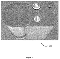
- the modular portable oxygen generator further includes an oxygen level indicator for indicating amount of oxygen left in the storage tank and showing user when to reload the next cartridge.
- the modular portable oxygen generator further includes intuitive flow control means to ensure flow of oxygen from the outlet at a steady rate and pressure.
- the present invention provides a modular portable oxygen generator, which is light weight, easy to carry and easy to use with minimal maintenance.
- the present design of the portable oxygen generator is a modification of the oxygen generator disclosed in the priority application.
- the entire design is based on the same concept of having a cartridge holding water and one or more chemicals separately.
- the entire arrangement is modular so that the various parts can be manufactured separately and assembled together with ease.
- the oxygen generator disclosed herein is capable to administering the oxygen at a steady pace during the time of changing of the cartridge also (please mention other new features also).
- the modular portable oxygen generator includes a reactor container having two vertical compartments, where one of the compartments houses a cartridge while another houses oxygen storage tank.
- the arrangement is provided with a mechanism to guide the oxygen generated in the cartridge after triggering to a defined outlet.
- FIG. 1 The schematic diagram of as given in Figure 1 provides the detailed arrangement of the modular portable oxygen generator, according to the embodiment.
- the reactor container 102 having first vertical compartment 104 and second vertical compartment 106. Where both the compartments are adjacently placed.
- the first vertical compartment 104 includes an opening at top end configured to house a cartridge 108. Through this opening the cartridge 108 is loaded in the first vertical compartment 104.
- a reactor enclosure 110 covering the opening at top end of the first vertical compartment 104.
- the reactor enclosure110 having an inward protrusion in its center acting as a cartridge trigger for triggering release of oxygen in the cartridge 108.
- the reactor enclosure is also designed to act as cartridge lock once the cartridge 108 is loaded.
- a cartridge slot followed by the opening at top end the first vertical compartment acting as a designated area compatible with shape of the cartridge to load the cartridge 108.
- a cartridge cover 112 which surrounds the loaded cartridge 108 acting as an insulator.
- the second vertical compartment 106 includes a storage tank 120 having an opening in its bottom to receive the oxygen released in the cartridge 108 and another opening at the top for release of oxygen stored inside it.
- a pressure gauge 122 connected via pipe to the opening at the top of the storage tank 120 to maintain release pressure of the oxygen stored in the storage tank 120.
- a humidifier 124 to humidify the oxygen to be released since the oxygen so released would be dry for breathing purposes.
- An opening is provided for allowing refill of water in the humidifier.
- the outlet is connected to a pipe leading to a breathing mask which could be administered to a user.
- the pipe assembly 126 connects the hollow connector 114 (via one way valve 116) of the first vertical compartment 104 and the storage tank 120.
- the pipe assembly 126 receives the oxygen generated in the cartridge 108 and delivers it to the storage tank 120.
- Bottom of the first vertical compartment 104 and second vertical compartment 106 is sealed by a common base structure 128, which may or may not be segmented.
- the cartridge 108 used herein is one of the key components of oxygen generator 100.
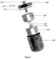
- the schematic diagram of as given in Figure 2 illustrates exploded view of detailed arrangement of parts of the cartridge 108, according to the embodiment.
- the Figure 3 illustrates the vertical section view of the cartridge 108.
- the cartridge 108 includes a cartridge cap 202 which has an opening in center and a cartridge outer shell 204 both fit together to form a closed elongate cartridge container.
- a gasket is provided for tight fitting of the cartridge cap 202 and the cartridge outer shell 204.
- Below the cartridge cap 202 a water chamber 208 is positioned.
- the water chamber 208 is partially filled with water while having openings at top end and at bottom.
- Below the water chamber 208 a chemical chamber 210 having filled with one or more chemicals in sealed condition.
- the chemical chamber 210 has an opening at its top positioned below the bottom opening of the water chamber 208.
- a plunger 206 longitudinally slidably mounted in the cartridge 108.
- the plunger 206 mounted in such a way that it passes through the opening in the cartridge cap 202 reaches till bottom of the water chamber 208 while traversing through the opening at top end and bottom end of the water chamber 208.
- the plunger is sized to fit tightly in the openings so that preventing the seepage of water from the water chamber 208.
- the top portion of the plunger has a disc shape protruding out of the opening in the cartridge cap 202, where the disc is positioned just below the inward protrusion the reactor enclosure, thereby forming part of the cartridge triggering mechanism.
- the plunger 206 is hollow in center lengthwise till its top portion so that the oxygen produced in the chemical chamber could pass through the plunger. Therefore, the plunger also acts as a part of gas passage.
- One or more retraction means 212 is/are positioned at bottom portion of the plunger 206 for retracting the plunger 206 during triggering of the cartridge 108 and to enabling longitudinal slide of the plunger 206.
- one or more springs are used as the retraction means 212.
- the cartridge is designed to have a gas passage ( Figure 7 ) for the release of the oxygen produced in the chemical chamber 210.
- the cartridge is also provided with a safety cap 218 placed below the disc shape protrusion of the plunger 206 and so as to avoid accidental triggering of the cartridge. Therefore, before triggering the cartridge the safety cap 218 has to be removed.
- the cartridge is replaceable and refillable.
- the gas passage for the release of the oxygen produced in the chemical chamber 210 includes the central hollow portion of the plunger 206 opening in the chemical chamber 210, gap between external diameter of water chamber 208 and internal diameter of the cartridge outer shell 204, extending to gap between external diameter of chemical chamber 210 and internal diameter of the cartridge outer shell 204, and opening on bottom of the cartridge outer shell 204 sealed by the hollow connector 114 guarded by one-way valve 116 ( Figure 7 ).
- the gas passage for the release of the oxygen produced in the chemical chamber 210 includes the central hollow portion of the plunger 206 opening in the chemical chamber 210, gap between external diameter of water chamber 208 and internal diameter of the cartridge outer shell 204, extending to gap between external diameter of chemical chamber 210 and internal diameter of the cartridge outer shell 204, and an opening in cartridge outer shell 204 is on its side wall or top guarded by one-way valve (not shown in Figures).
- the connection point of the pipe assembly is adjusted to connect to the opening on side wall or top of cartridge outer shell.
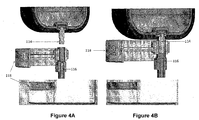
- FIGS 4A & 4B Movement and function of the release ring 118 attached to the hollow connector are illustrated in Figures 4A & 4B .
- the Figure 4A depicts the condition when cartridge is unloaded, while Figure 4B depicts when cartridge is loaded.
- the bottom opening of the cartridge outer shell 204 locks in to the one-way valve 116 thereby allowing the flow of oxygen generated in the cartridge 108.
- the release ring 118 also locks the cartridge 108 when loaded and the release ring 118 being attached to the hollow connector 114 when moved down also releases the cartridge 118 so that next cartridge 108 can be loaded. Pressing cartridge into the cartridge slot locks the cartridge into first vertical compartment.
- release ring 118 Before inserting cartridge 108, release ring 118 will show red status as first vertical compartment 104 is empty or cartridge 108 is not inserted properly. After inserting cartridge the release ring will show status as green which means the modular portable oxygen generator is ready to use and cartridge is inserted properly.
- the modular portable oxygen generator 100 includes an oxygen level indicator for indicating amount of oxygen left in the storage tank and showing user when to reload the next cartridge. It may also include intuitive flow control means to ensure flow of oxygen from the outlet at a steady rate and pressure ( Figure 5 ).
- the one or more chemicals filled in the chemical chamber 210 for generating oxygen are selected from a group sodium percarbonate, potassium superoxide, peroxide species (hydrogen peroxide), urea-hydrogen peroxide and percarbamide peroxide.
- the chemical may be sodium percarbonate.
- the sodium percarbonate naturally decomposes, very slowly, to form sodium carbonate and hydrogen peroxide.
- the hydrogen peroxide further decomposes to form water and oxygen and liberate some heat (exothermic reaction).
- the chemical reaction is as follows: 2Na 2 CO 3 • 3H 2 O 2 ⁇ 2Na 2 CO 3 + 3H 2 O + 1.5 O 2 + Heat
- the one or more chemicals used herein could be in the form of granular powder or pellets or powder in a porous pouch or candle stick or combination thereof.
- any of the other suitable catalyst may also be used to generate oxygen in a controlled rate, without departing from the scope of the invention.
- the one or more chemical and the water can be taken in predefined ratios for optimum generation of oxygen.
- the safety cap 218 is removed from the cartridge 108 and loaded in the cartridge slot.
- the reactor enclosure 110 is closed to lock the cartridge 108 inside.
- the closing of the reactor enclosure 110 presses the top portion of the plunger 206 having a disc shape, which leads to piercing of the film 214 thereby allowing water to flow from water chamber 208 to chemical chamber and eventually react with the one or more chemicals generating oxygen.
- the Figure 6A depicts the initial condition of the plunger 206 when it has not pierced the film 214, while Figure 6B depicts the pierced condition.
- the Figure 7 illustrates the flow of the oxygen generated in the chemical chamber according to an embodiment of the present invention.
- the direction of flow is depicting by arrows, which starts from the gas passage leading to the storage tank via pipe assembly and finally exiting through the outlet.
- the present invention is advantageous for being able to maintain continuous administration of oxygen from the storage tank even during reloading of the cartridges.
- mechanism in the first vertical compartment 104 does not allow the cartridge 108 to be removed until all the oxygen produced inside the cartridge 108 is collected in the storage tank 120.
- the mechanism does not allow further loading of cartridges in the first vertical compartment 104.
- structure of the modular portable oxygen generator and its components can be made up of non-reactive, non-corrosive materials such as, but not limited to, plastic, silicon, and the like.
Landscapes
- Health & Medical Sciences (AREA)
- Engineering & Computer Science (AREA)
- Emergency Medicine (AREA)
- General Health & Medical Sciences (AREA)
- Pulmonology (AREA)
- Veterinary Medicine (AREA)
- Public Health (AREA)
- Life Sciences & Earth Sciences (AREA)
- Animal Behavior & Ethology (AREA)
- Anesthesiology (AREA)
- Biomedical Technology (AREA)
- Heart & Thoracic Surgery (AREA)
- Hematology (AREA)
- General Engineering & Computer Science (AREA)
- Mechanical Engineering (AREA)
- Emergency Management (AREA)
- Business, Economics & Management (AREA)
- Oxygen, Ozone, And Oxides In General (AREA)
- Respiratory Apparatuses And Protective Means (AREA)
Claims (11)
- Ein modularer tragbarer Sauerstoffgenerator (100), umfassend:einen Reaktionsbehälter (102) mit einem ersten vertikalen Segment (104) und einem zweiten vertikalen Segment (106);wobei das erste vertikale Segment (104) Folgendes aufweist:eine zum Unterbringen einer Patrone (108) ausgelegte Öffnung am oberen Ende,die in dem ersten vertikalen Segment (104) untergebrachte Patrone (108),eine Reaktionsbehälterhülle (110), die die Öffnung am oberen Ende des ersten vertikalen Segments (104) abdeckt und in der Mitte einen Vorsprung nach innen aufweist, um als Patronenauslöser zu wirken und so die Freisetzung von Sauerstoff in die Patrone auszulösen,einen Patronensitz gefolgt von der Öffnung am oberen Ende,eine Patronenabdeckung (112), die die Patrone umgibt,eine Öffnung unten, seitlich oder oben an dem ersten vertikalen Segment (104), die von einem hohlen Verbinder (114) geschützt wird, auf die ein Ein-Wege-Ventil (116) folgt, das für den in der Patrone freigesetzten Sauerstoffstrom geeignet ist, undeinen an dem hohlen Verbinder (114) befestigten Freigabering (118), wobei der Freigabering (118) geeignet ist, nach unten gedrückt zu werden, um den hohlen Verbinder (114) zu bewegen;wobei das zweite vertikale Segment (106) Folgendes aufweist:einen Speichertank (120), der geeignet ist, den in der Patrone freigesetzten Sauerstoff aufzunehmen,einen Druckmesser (122), der geeignet ist, den Druck des freizusetzenden Sauerstoffs zu erhalten,einen Befeuchter (124), der geeignet ist, den freizusetzenden Sauerstoff zu befeuchten, undeinen Auslass für den befeuchteten Sauerstoff;eine Rohrmontage (126), die den hohlen Verbinder (114) des ersten vertikalen Segments (104) und den Speichertank (120) verbindet; undeinen Unterbau (128), der den Boden des ersten vertikalen Segments (104) und des zweiten vertikalen Segments (106) abdichtet.
- Modularer tragbarer Sauerstoffgenerator (100) nach Anspruch 1, bei dem der Freigabering (118) außerdem die Patrone (108) verriegelt, wenn sie geladen ist, und der an dem hohlen Verbinder (114) befestigte Freigabering (118), wenn er nach unten bewegt wird, auch die Patrone (108) freigibt, so dass die nächste Patrone geladen werden kann.
- Modularer tragbarer Sauerstoffgenerator (100) nach Anspruch 1, bei dem während des Ladens der Patrone (108) die Bodenöffnung der Patronenaußenhülle (204) in das Ein-Wege-Ventil einrastet und es so dem in der Patrone (108) erzeugten Sauerstoffstrom gestattet zu fließen.
- Modularer tragbarer Sauerstoffgenerator (100) nach Anspruch 1, bei dem die Patrone Folgendes umfasst:eine Patronenkappe (202) mit einer Öffnung in der Mitte und eine Patronenaußenhülle (204) die zusammengefügt einen geschlossenen länglichen Patronenbehälter bilden, in dem die Patronenaußenhülle (204) eine der Öffnung an der Unterseite des ersten vertikalen Segments (104) entsprechende Öffnung aufweist;eine Wasserkammer (208) mit einer Öffnung am oberen Ende und einer Öffnung am Boden;eine chemische Kammer (210), die mit einer oder mehreren Chemikalien in versiegelter Form gefüllt ist und eine unter der Bodenöffnung der Wasserkammer (208) positionierte Öffnung aufweist;einen Kolben (206), der seitlich verschiebbar in der Patrone (108) montiert ist und durch die Öffnung in der Patronenkappe (202) bis zum Boden der Wasserkammer (208) verläuft und dabei die Öffnung am oberen Ende und am unteren Ende der Wasserkammer (208) überquert, wobeidie Größe des Kolbens (206) so ausgelegt ist, dass er abdichtend in den Öffnungen sitzt,wobei der obere Teil des Kolbens (206) scheibenförmig ist und aus der Öffnung in der Patronenkappe vorsteht, wo die Scheibe unter dem Vorsprung der Reaktionsbehälterhülle nach innen positioniert ist,wobei der Kolben (206) in der Mitte in Längsrichtung bis zum oberen Teil hohl ist, undRückholvorrichtungen (212) für den Kolben am Bodenteil des Kolbens (206), um die Längsverschiebung des Kolbens (206) zu gestatten;einen Gasdurchgang zum Freisetzen des in der chemischen Kammer (210) erzeugten Sauerstoffs; undeine Schutzkappe (218) unter dem scheibenförmigen Vorsprung des Kolbens (206), um das versehentliche Auslösen der Patrone (108) zu vermeiden.
- Modularer tragbarer Sauerstoffgenerator (100) nach Anspruch 3, bei dem eine oder mehrere Chemikalien aus einer Gruppe von Natriumpercarbonat, Kaliumsuperoxid, Peroxidspezies (Wasserstoffperoxid), Hamstoff-Wasserstoffperoxid und Carbamidperoxid gewählt werden .
- Modularer tragbarer Sauerstoffgenerator (100) nach Anspruch 3, bei dem eine oder mehrere darin verwendete Chemikalien in Form von Granulatpulver, Pellets, eines Pulverbeutels oder in Kerzenform vorliegen.
- Modularer tragbarer Sauerstoffgenerator (100) nach Anspruch 3, bei dem der Gasdurchgang zum Freisetzen des in der chemischen Kammer (210) erzeugten Sauerstoffs Folgendes umfasst:den hohlen mittleren Teil der Öffnung des Kolbens (206) in der chemischen Kammer (210),einen Freiraum zwischen dem Außendurchmesser der Wasserkammer (208) und dem Innendurchmesser des Patronenbehälters bis zu dem Freiraum zwischen dem Außendurchmesser der chemischen Kammer (210) und dem Innendurchmesser der Patronenaußenhülle (204), undeine Öffnung am Boden der Patronenaußenhülle, die von dem hohlen Verbinder (114) abgedichtet wird.
- Modularer tragbarer Sauerstoffgenerator (100) nach Anspruch 4, bei dem die Patrone (108) geeignet ist, ein Auslöse-Input durch Schließen der Reaktionsbehälterhülle (110) zu empfangen, das zum Herunterdrücken des scheibenförmigen oberen Abschnitts des Kolbens (206) führt, was zum Durchstoßen einer Folie führt, so dass Wasser von der Wasserkammer (208) zu der chemischen Kammer (210) fließen und schließlich mit einer oder mehreren Chemikalien reagieren und so Sauerstoff erzeugen kann.
- Modularer tragbarer Sauerstoffgenerator (100) nach Anspruch 1, der außerdem eine Sauerstoffniveauanzeige zur Anzeige der im Speichertank verbliebenen Sauerstoffmenge umfasst, die dem Benutzer anzeigt, wann die nächste Patrone eingesetzt werden muss.
- Modularer tragbarer Sauerstoffgenerator (100) nach Anspruch 1, der außerdem intuitive Durchflusssteuerelemente umfasst, um den Sauerstoffstrom vom Auslass bei gleichmäßiger Geschwindigkeit und gleichbleibendem Druck zu garantieren.
- Modularer tragbarer Sauerstoffgenerator (100) nach Anspruch 1, bei dem die Patrone (108) austauschbar und nachfüllbar ist.
Applications Claiming Priority (2)
| Application Number | Priority Date | Filing Date | Title |
|---|---|---|---|
| IN201641005614 | 2016-02-18 | ||
| PCT/IN2017/000044 WO2017141264A1 (en) | 2016-02-18 | 2017-02-20 | Modular portable oxygen generator. |
Publications (3)
| Publication Number | Publication Date |
|---|---|
| EP3416713A1 EP3416713A1 (de) | 2018-12-26 |
| EP3416713A4 EP3416713A4 (de) | 2019-10-16 |
| EP3416713B1 true EP3416713B1 (de) | 2021-04-07 |
Family
ID=59624905
Family Applications (1)
| Application Number | Title | Priority Date | Filing Date |
|---|---|---|---|
| EP17752812.2A Active EP3416713B1 (de) | 2016-02-18 | 2017-02-20 | Modularer tragbarer sauerstoffgenerator |
Country Status (4)
| Country | Link |
|---|---|
| US (1) | US11000715B2 (de) |
| EP (1) | EP3416713B1 (de) |
| CN (1) | CN108136151B (de) |
| WO (2) | WO2017141263A1 (de) |
Families Citing this family (2)
| Publication number | Priority date | Publication date | Assignee | Title |
|---|---|---|---|---|
| US20200338372A1 (en) * | 2019-04-26 | 2020-10-29 | O2-Matic Products Private Limited | Oxygen generator |
| US12251519B2 (en) * | 2020-06-24 | 2025-03-18 | O2-Matic Products Private Limited | Portable oxygen generator system |
Family Cites Families (15)
| Publication number | Priority date | Publication date | Assignee | Title |
|---|---|---|---|---|
| US3574561A (en) * | 1969-07-24 | 1971-04-13 | Us Navy | Oxygen generator system utilizing alkali metal peroxides and superoxides |
| US3756785A (en) * | 1971-09-15 | 1973-09-04 | Ato Inc | Gas generator assembly |
| US3881394A (en) * | 1971-09-15 | 1975-05-06 | Ato Inc | Gas generator assembly |
| US5725834A (en) * | 1995-04-07 | 1998-03-10 | Daicel Chemical Industries, Ltd. | Chemical oxygen generator |
| US5620664A (en) | 1995-09-11 | 1997-04-15 | Palmer; Kenneth J. | Personal oxygen dispenser |
| JP2003306315A (ja) * | 2002-04-11 | 2003-10-28 | Sem:Kk | 酸素発生器 |
| GB0221451D0 (en) * | 2002-09-16 | 2002-10-23 | Molecular Oxygen Ltd | Gas generator |
| CN102784432B (zh) * | 2003-06-20 | 2015-09-02 | 瑞思迈有限公司 | 带有加湿器的可吸入气体设备 |
| US20050112035A1 (en) * | 2003-11-20 | 2005-05-26 | Julian Ross | Method and apparatus for generating oxygen |
| TW200606101A (en) * | 2004-08-02 | 2006-02-16 | Dream Works Co Ltd | Oxygen generator and cartridge therefor |
| US20090081115A1 (en) * | 2007-01-16 | 2009-03-26 | Oxysure Systems Inc. | Method and apparatus for actuating a chemical reaction |
| CN201425024Y (zh) * | 2009-05-15 | 2010-03-17 | 南通炜创机械配件制造有限公司 | 螺杆式空压机进气阀 |
| CN103458951B (zh) * | 2011-01-06 | 2016-06-01 | 亿诺医疗公司 | 气体输送设备与系统 |
| JP2012200387A (ja) * | 2011-03-25 | 2012-10-22 | Fujikura Rubber Ltd | 酸素濃縮装置用酸素タンクユニット |
| GB201321996D0 (en) * | 2013-12-12 | 2014-01-29 | Molecular Oxygen Ltd | Oxygen generators |
-
2017
- 2017-02-20 EP EP17752812.2A patent/EP3416713B1/de active Active
- 2017-02-20 US US15/763,665 patent/US11000715B2/en not_active Expired - Fee Related
- 2017-02-20 WO PCT/IN2017/000043 patent/WO2017141263A1/en not_active Ceased
- 2017-02-20 WO PCT/IN2017/000044 patent/WO2017141264A1/en not_active Ceased
- 2017-02-20 CN CN201780003421.1A patent/CN108136151B/zh not_active Expired - Fee Related
Non-Patent Citations (1)
| Title |
|---|
| None * |
Also Published As
| Publication number | Publication date |
|---|---|
| WO2017141263A1 (en) | 2017-08-24 |
| WO2017141264A1 (en) | 2017-08-24 |
| US20180345051A1 (en) | 2018-12-06 |
| CN108136151A (zh) | 2018-06-08 |
| EP3416713A1 (de) | 2018-12-26 |
| EP3416713A4 (de) | 2019-10-16 |
| US11000715B2 (en) | 2021-05-11 |
| CN108136151B (zh) | 2021-06-08 |
Similar Documents
| Publication | Publication Date | Title |
|---|---|---|
| US7171964B2 (en) | Instant chemical based flexible oxygen in a non-pressurized flexible or rigid containment system | |
| EP2186537A1 (de) | Inhalator mit einem Wasserstoffgenerator | |
| AU2007101247A4 (en) | Method and system for providing breathable air in a closed circuit | |
| US7165546B2 (en) | Nitrous oxide based oxygen supply system | |
| US5706799A (en) | Oxygen respirator having CO2 absorption means | |
| US4409978A (en) | Portable, self-contained breathing apparatus | |
| KR102091547B1 (ko) | 휴대용 산소발생장치 | |
| US20090250062A1 (en) | Pressure activated device and breathing system | |
| EP3416713B1 (de) | Modularer tragbarer sauerstoffgenerator | |
| KR20100041266A (ko) | 휴대용 자가 산소호흡장치 및 이를 구비한 마스크 | |
| US2507450A (en) | Oxygen generator with integrated initiating device | |
| CA3114155C (en) | Individual closed-circuit rebreather for underwater diving | |
| US20200179693A1 (en) | Systems, devices, and methods for providing electrotherapy | |
| GB1574673A (en) | Respiratory apparatus | |
| US20070048201A1 (en) | Oxygen generation system and method | |
| JP2007159903A (ja) | 炭酸ガス補充装置 | |
| JP2001139306A (ja) | 簡易式酸素発生器 | |
| HK40039868A (en) | Individual closed-circuit rebreather for underwater diving | |
| ITME20010017A1 (it) | Respiratore economico ad ossigeno a circuito chiuso-ciclo utilizzabile in acqua in camera di decompressione o respirazione normobarica model |
Legal Events
| Date | Code | Title | Description |
|---|---|---|---|
| STAA | Information on the status of an ep patent application or granted ep patent |
Free format text: STATUS: THE INTERNATIONAL PUBLICATION HAS BEEN MADE |
|
| PUAI | Public reference made under article 153(3) epc to a published international application that has entered the european phase |
Free format text: ORIGINAL CODE: 0009012 |
|
| STAA | Information on the status of an ep patent application or granted ep patent |
Free format text: STATUS: REQUEST FOR EXAMINATION WAS MADE |
|
| 17P | Request for examination filed |
Effective date: 20180326 |
|
| AK | Designated contracting states |
Kind code of ref document: A1 Designated state(s): AL AT BE BG CH CY CZ DE DK EE ES FI FR GB GR HR HU IE IS IT LI LT LU LV MC MK MT NL NO PL PT RO RS SE SI SK SM TR |
|
| AX | Request for extension of the european patent |
Extension state: BA ME |
|
| DAV | Request for validation of the european patent (deleted) | ||
| DAX | Request for extension of the european patent (deleted) | ||
| A4 | Supplementary search report drawn up and despatched |
Effective date: 20190912 |
|
| RIC1 | Information provided on ipc code assigned before grant |
Ipc: C01B 13/02 20060101ALI20190906BHEP Ipc: A62B 21/00 20060101ALI20190906BHEP Ipc: A61M 16/10 20060101AFI20190906BHEP |
|
| GRAP | Despatch of communication of intention to grant a patent |
Free format text: ORIGINAL CODE: EPIDOSNIGR1 |
|
| STAA | Information on the status of an ep patent application or granted ep patent |
Free format text: STATUS: GRANT OF PATENT IS INTENDED |
|
| INTG | Intention to grant announced |
Effective date: 20201014 |
|
| GRAS | Grant fee paid |
Free format text: ORIGINAL CODE: EPIDOSNIGR3 |
|
| GRAA | (expected) grant |
Free format text: ORIGINAL CODE: 0009210 |
|
| STAA | Information on the status of an ep patent application or granted ep patent |
Free format text: STATUS: THE PATENT HAS BEEN GRANTED |
|
| AK | Designated contracting states |
Kind code of ref document: B1 Designated state(s): AL AT BE BG CH CY CZ DE DK EE ES FI FR GB GR HR HU IE IS IT LI LT LU LV MC MK MT NL NO PL PT RO RS SE SI SK SM TR |
|
| REG | Reference to a national code |
Ref country code: GB Ref legal event code: FG4D |
|
| REG | Reference to a national code |
Ref country code: AT Ref legal event code: REF Ref document number: 1378881 Country of ref document: AT Kind code of ref document: T Effective date: 20210415 Ref country code: CH Ref legal event code: EP |
|
| REG | Reference to a national code |
Ref country code: DE Ref legal event code: R096 Ref document number: 602017036237 Country of ref document: DE |
|
| REG | Reference to a national code |
Ref country code: IE Ref legal event code: FG4D |
|
| REG | Reference to a national code |
Ref country code: LT Ref legal event code: MG9D |
|
| REG | Reference to a national code |
Ref country code: NL Ref legal event code: MP Effective date: 20210407 Ref country code: AT Ref legal event code: MK05 Ref document number: 1378881 Country of ref document: AT Kind code of ref document: T Effective date: 20210407 |
|
| PG25 | Lapsed in a contracting state [announced via postgrant information from national office to epo] |
Ref country code: NL Free format text: LAPSE BECAUSE OF FAILURE TO SUBMIT A TRANSLATION OF THE DESCRIPTION OR TO PAY THE FEE WITHIN THE PRESCRIBED TIME-LIMIT Effective date: 20210407 Ref country code: HR Free format text: LAPSE BECAUSE OF FAILURE TO SUBMIT A TRANSLATION OF THE DESCRIPTION OR TO PAY THE FEE WITHIN THE PRESCRIBED TIME-LIMIT Effective date: 20210407 Ref country code: BG Free format text: LAPSE BECAUSE OF FAILURE TO SUBMIT A TRANSLATION OF THE DESCRIPTION OR TO PAY THE FEE WITHIN THE PRESCRIBED TIME-LIMIT Effective date: 20210707 Ref country code: AT Free format text: LAPSE BECAUSE OF FAILURE TO SUBMIT A TRANSLATION OF THE DESCRIPTION OR TO PAY THE FEE WITHIN THE PRESCRIBED TIME-LIMIT Effective date: 20210407 Ref country code: FI Free format text: LAPSE BECAUSE OF FAILURE TO SUBMIT A TRANSLATION OF THE DESCRIPTION OR TO PAY THE FEE WITHIN THE PRESCRIBED TIME-LIMIT Effective date: 20210407 Ref country code: LT Free format text: LAPSE BECAUSE OF FAILURE TO SUBMIT A TRANSLATION OF THE DESCRIPTION OR TO PAY THE FEE WITHIN THE PRESCRIBED TIME-LIMIT Effective date: 20210407 |
|
| PG25 | Lapsed in a contracting state [announced via postgrant information from national office to epo] |
Ref country code: IS Free format text: LAPSE BECAUSE OF FAILURE TO SUBMIT A TRANSLATION OF THE DESCRIPTION OR TO PAY THE FEE WITHIN THE PRESCRIBED TIME-LIMIT Effective date: 20210807 Ref country code: GR Free format text: LAPSE BECAUSE OF FAILURE TO SUBMIT A TRANSLATION OF THE DESCRIPTION OR TO PAY THE FEE WITHIN THE PRESCRIBED TIME-LIMIT Effective date: 20210708 Ref country code: PT Free format text: LAPSE BECAUSE OF FAILURE TO SUBMIT A TRANSLATION OF THE DESCRIPTION OR TO PAY THE FEE WITHIN THE PRESCRIBED TIME-LIMIT Effective date: 20210809 Ref country code: LV Free format text: LAPSE BECAUSE OF FAILURE TO SUBMIT A TRANSLATION OF THE DESCRIPTION OR TO PAY THE FEE WITHIN THE PRESCRIBED TIME-LIMIT Effective date: 20210407 Ref country code: NO Free format text: LAPSE BECAUSE OF FAILURE TO SUBMIT A TRANSLATION OF THE DESCRIPTION OR TO PAY THE FEE WITHIN THE PRESCRIBED TIME-LIMIT Effective date: 20210707 Ref country code: PL Free format text: LAPSE BECAUSE OF FAILURE TO SUBMIT A TRANSLATION OF THE DESCRIPTION OR TO PAY THE FEE WITHIN THE PRESCRIBED TIME-LIMIT Effective date: 20210407 Ref country code: SE Free format text: LAPSE BECAUSE OF FAILURE TO SUBMIT A TRANSLATION OF THE DESCRIPTION OR TO PAY THE FEE WITHIN THE PRESCRIBED TIME-LIMIT Effective date: 20210407 Ref country code: RS Free format text: LAPSE BECAUSE OF FAILURE TO SUBMIT A TRANSLATION OF THE DESCRIPTION OR TO PAY THE FEE WITHIN THE PRESCRIBED TIME-LIMIT Effective date: 20210407 |
|
| REG | Reference to a national code |
Ref country code: DE Ref legal event code: R097 Ref document number: 602017036237 Country of ref document: DE |
|
| PG25 | Lapsed in a contracting state [announced via postgrant information from national office to epo] |
Ref country code: EE Free format text: LAPSE BECAUSE OF FAILURE TO SUBMIT A TRANSLATION OF THE DESCRIPTION OR TO PAY THE FEE WITHIN THE PRESCRIBED TIME-LIMIT Effective date: 20210407 Ref country code: DK Free format text: LAPSE BECAUSE OF FAILURE TO SUBMIT A TRANSLATION OF THE DESCRIPTION OR TO PAY THE FEE WITHIN THE PRESCRIBED TIME-LIMIT Effective date: 20210407 Ref country code: CZ Free format text: LAPSE BECAUSE OF FAILURE TO SUBMIT A TRANSLATION OF THE DESCRIPTION OR TO PAY THE FEE WITHIN THE PRESCRIBED TIME-LIMIT Effective date: 20210407 Ref country code: RO Free format text: LAPSE BECAUSE OF FAILURE TO SUBMIT A TRANSLATION OF THE DESCRIPTION OR TO PAY THE FEE WITHIN THE PRESCRIBED TIME-LIMIT Effective date: 20210407 Ref country code: ES Free format text: LAPSE BECAUSE OF FAILURE TO SUBMIT A TRANSLATION OF THE DESCRIPTION OR TO PAY THE FEE WITHIN THE PRESCRIBED TIME-LIMIT Effective date: 20210407 Ref country code: SM Free format text: LAPSE BECAUSE OF FAILURE TO SUBMIT A TRANSLATION OF THE DESCRIPTION OR TO PAY THE FEE WITHIN THE PRESCRIBED TIME-LIMIT Effective date: 20210407 Ref country code: SK Free format text: LAPSE BECAUSE OF FAILURE TO SUBMIT A TRANSLATION OF THE DESCRIPTION OR TO PAY THE FEE WITHIN THE PRESCRIBED TIME-LIMIT Effective date: 20210407 |
|
| PLBE | No opposition filed within time limit |
Free format text: ORIGINAL CODE: 0009261 |
|
| STAA | Information on the status of an ep patent application or granted ep patent |
Free format text: STATUS: NO OPPOSITION FILED WITHIN TIME LIMIT |
|
| 26N | No opposition filed |
Effective date: 20220110 |
|
| PGFP | Annual fee paid to national office [announced via postgrant information from national office to epo] |
Ref country code: IE Payment date: 20220224 Year of fee payment: 6 Ref country code: GB Payment date: 20220222 Year of fee payment: 6 Ref country code: DE Payment date: 20220225 Year of fee payment: 6 Ref country code: CH Payment date: 20220224 Year of fee payment: 6 |
|
| PG25 | Lapsed in a contracting state [announced via postgrant information from national office to epo] |
Ref country code: IS Free format text: LAPSE BECAUSE OF FAILURE TO SUBMIT A TRANSLATION OF THE DESCRIPTION OR TO PAY THE FEE WITHIN THE PRESCRIBED TIME-LIMIT Effective date: 20210807 Ref country code: AL Free format text: LAPSE BECAUSE OF FAILURE TO SUBMIT A TRANSLATION OF THE DESCRIPTION OR TO PAY THE FEE WITHIN THE PRESCRIBED TIME-LIMIT Effective date: 20210407 |
|
| PGFP | Annual fee paid to national office [announced via postgrant information from national office to epo] |
Ref country code: FR Payment date: 20220222 Year of fee payment: 6 Ref country code: BE Payment date: 20220224 Year of fee payment: 6 |
|
| PG25 | Lapsed in a contracting state [announced via postgrant information from national office to epo] |
Ref country code: MC Free format text: LAPSE BECAUSE OF FAILURE TO SUBMIT A TRANSLATION OF THE DESCRIPTION OR TO PAY THE FEE WITHIN THE PRESCRIBED TIME-LIMIT Effective date: 20210407 |
|
| PG25 | Lapsed in a contracting state [announced via postgrant information from national office to epo] |
Ref country code: LU Free format text: LAPSE BECAUSE OF NON-PAYMENT OF DUE FEES Effective date: 20220220 |
|
| REG | Reference to a national code |
Ref country code: DE Ref legal event code: R119 Ref document number: 602017036237 Country of ref document: DE |
|
| REG | Reference to a national code |
Ref country code: CH Ref legal event code: PL |
|
| REG | Reference to a national code |
Ref country code: BE Ref legal event code: MM Effective date: 20230228 |
|
| GBPC | Gb: european patent ceased through non-payment of renewal fee |
Effective date: 20230220 |
|
| PG25 | Lapsed in a contracting state [announced via postgrant information from national office to epo] |
Ref country code: LI Free format text: LAPSE BECAUSE OF NON-PAYMENT OF DUE FEES Effective date: 20230228 Ref country code: CH Free format text: LAPSE BECAUSE OF NON-PAYMENT OF DUE FEES Effective date: 20230228 |
|
| PGFP | Annual fee paid to national office [announced via postgrant information from national office to epo] |
Ref country code: IT Payment date: 20230811 Year of fee payment: 7 |
|
| REG | Reference to a national code |
Ref country code: IE Ref legal event code: MM4A |
|
| PG25 | Lapsed in a contracting state [announced via postgrant information from national office to epo] |
Ref country code: GB Free format text: LAPSE BECAUSE OF NON-PAYMENT OF DUE FEES Effective date: 20230220 |
|
| PG25 | Lapsed in a contracting state [announced via postgrant information from national office to epo] |
Ref country code: IE Free format text: LAPSE BECAUSE OF NON-PAYMENT OF DUE FEES Effective date: 20230220 Ref country code: GB Free format text: LAPSE BECAUSE OF NON-PAYMENT OF DUE FEES Effective date: 20230220 Ref country code: FR Free format text: LAPSE BECAUSE OF NON-PAYMENT OF DUE FEES Effective date: 20230228 Ref country code: DE Free format text: LAPSE BECAUSE OF NON-PAYMENT OF DUE FEES Effective date: 20230901 |
|
| PG25 | Lapsed in a contracting state [announced via postgrant information from national office to epo] |
Ref country code: BE Free format text: LAPSE BECAUSE OF NON-PAYMENT OF DUE FEES Effective date: 20230228 |
|
| PG25 | Lapsed in a contracting state [announced via postgrant information from national office to epo] |
Ref country code: HU Free format text: LAPSE BECAUSE OF FAILURE TO SUBMIT A TRANSLATION OF THE DESCRIPTION OR TO PAY THE FEE WITHIN THE PRESCRIBED TIME-LIMIT; INVALID AB INITIO Effective date: 20170220 |
|
| PG25 | Lapsed in a contracting state [announced via postgrant information from national office to epo] |
Ref country code: MK Free format text: LAPSE BECAUSE OF FAILURE TO SUBMIT A TRANSLATION OF THE DESCRIPTION OR TO PAY THE FEE WITHIN THE PRESCRIBED TIME-LIMIT Effective date: 20210407 Ref country code: CY Free format text: LAPSE BECAUSE OF FAILURE TO SUBMIT A TRANSLATION OF THE DESCRIPTION OR TO PAY THE FEE WITHIN THE PRESCRIBED TIME-LIMIT Effective date: 20210407 |
|
| PG25 | Lapsed in a contracting state [announced via postgrant information from national office to epo] |
Ref country code: TR Free format text: LAPSE BECAUSE OF FAILURE TO SUBMIT A TRANSLATION OF THE DESCRIPTION OR TO PAY THE FEE WITHIN THE PRESCRIBED TIME-LIMIT Effective date: 20210407 |
|
| PG25 | Lapsed in a contracting state [announced via postgrant information from national office to epo] |
Ref country code: MT Free format text: LAPSE BECAUSE OF FAILURE TO SUBMIT A TRANSLATION OF THE DESCRIPTION OR TO PAY THE FEE WITHIN THE PRESCRIBED TIME-LIMIT Effective date: 20210407 |
|
| PG25 | Lapsed in a contracting state [announced via postgrant information from national office to epo] |
Ref country code: IT Free format text: LAPSE BECAUSE OF NON-PAYMENT OF DUE FEES Effective date: 20240220 |